GS-5416PLC - Network switch Edimax - Free user manual and instructions
Find the device manual for free GS-5416PLC Edimax in PDF.

User questions about GS-5416PLC Edimax
0 question about this device. Answer the ones you know or ask your own.
Ask a new question about this device
Download the instructions for your Network switch in PDF format for free! Find your manual GS-5416PLC - Edimax and take your electronic device back in hand. On this page are published all the documents necessary for the use of your device. GS-5416PLC by Edimax.
USER MANUAL GS-5416PLC Edimax
GS-5416PLC / GS-5424PLC
User Manual
11-2020 / v1.1
Edimax Technology Co., Ltd.
No. 278, Xinhu 1st Rd., Neihu Dist., Taipei City, Taiwan
Email: support@edimax.com.tw
Edimax Technology Europe B.V.
Fijenhof 2, 5652 AE Eindhoven, The Netherlands
Email: support@edimax.nl
Edimax Computer Company
3444 De La Cruz Blvd., Santa Clara, CA 95054, USA
Live Tech Support: 1(800) 652-6776
Email: support@edimax.com
I Introducon....1
I-1 Overview 1
I-2 Package Content....1
I-3 Features....2
I-4 Product Components....2
I-4-1 Ports....2
I-4-2 LED Indicators....3
II Installaon....4
II-1 Mounng the Switch....4
II-1-1 Placement Tips....4
II-1-2 Desktop Mounng....5
II-1-3 Rack Mounng....5
III Geng Started 7
III-1 Connecng to Power 7
III-2 Connecng to Network 8
III-3 Power over Ethernet (PoE) Consideraons....9
III-4 Starng the Web-based Conguraon Utility....10
III-4-1 Logging In.... 12
III-4-2 Logging Out....13
IV Web-based Switch Conguraon....15
IV-1 Status....16
IV-1-1 System Informaon....16
IV-1-2 Logging Message....18
IV-1-3 Port 19
IV-1-4 Link Aggregaon 24
IV-1-5 MAC Address Table....25
IV-2 Network....26
IV-2-1 IP Address 26
IV-2-2 System Time 29
IV-3 Port....31
IV-3-1 Port Seng....31
IV-3-2 Long Range Mode 34
IV-3-3 Error Disable 35
IV-3-4 Link Aggregaon 36
IV-3-5 Jumbo Frame 43
IV-4 PoE....44
IV-4-1 Global Seng 44
IV-4-2 Priority Seng....46
IV-4-3 Power Limit....47
IV-4-4 PoE Status....49
IV-4-5 PD (Powered Device) Alive Check....50
IV-5 VLAN....52
IV-5-1 VLAN 52
IV-5-2 Voice VLAN 60
IV-5-3 MAC VLAN 63
IV-6 MAC Address Table 66
IV-6-1 Dynamic Address 66
IV-6-2 Stac Address....66
IV-6-3 Filtering Address....67
IV-7 Spanning Tree....68
IV-7-1 Property....68
IV-7-2 Port Seng....70
IV-7-3 MST Instance 72
IV-7-4 MST Port Seng....74
IV-7-5 Stascs....76
IV-8 Discovery....78
IV-8-1 LLDP 78
IV-9 Mulcast 95
IV-9-1 General 95
IV-9-2 IGMP Snooping....100
IV-9-3 MVR....107
IV-10 Security....112
IV-10-1 RADIUS....112
IV-10-2 Management Access....115
IV-10-3 Authencaon Manager.... 121
IV-10-4 Port Security.... 131
IV-10-5 Protected Port....133
IV-10-6 Storm Control.... 135
IV-10-7 DoS....137
IV-10-8 DHCP Snooping 141
IV-10-9 IP Source Guard....149
IV-11 ACL....154
IV-11-1 MAC ACL....154
IV-11-2 MAC ACE 155
IV-11-3 IPv4 ACL 157
IV-11-4 IPv4 ACE 158
IV-11-5 ACL Binding 162
IV-12 QoS....164
IV-12-1 General....164
IV-12-2 Rate Limit 172
IV-13 Diagnoscs 175
IV-13-1 Logging 175
IV-13-2 Mirroring....177
IV-13-3 Ping 179
IV-13-4 Traceroute....180
IV-13-5 Copper Test....181
IV-13-6 Fiber Module....182
IV-13-7 UDLD 183
IV-14 Management....186
IV-14-1 User Account.... 186
IV-14-2 Fireware 188
IV-14-3 Conguraon 192
IV-14-4 SNMP 196
Thank you for choosing a Edimax (PoE) WEB Smart Ethernet Switch. This device is designed to be operaonal right out-of-the-box as a standard bridge. In the default conguraon, it will forward packets between connecng devices aer powered up.
Before you begin installing the switch, make sure you have all of the package contents available, and a PC with a web browser for using web-based system management tools.
I-1 Overview
The Edimax GS-54XXPLC Series Smart Switch features 4 RJ45 and 4 SFP Combo ports. The GS-5416PLC and GS-5424PLC come with 16 and 24 Gigabit PoE+ ports respectively.
I-2 Package Content
Before using the product, check that the items listed below are included and in good condition. If any item does not accord with the table, please contact your dealer immediately.
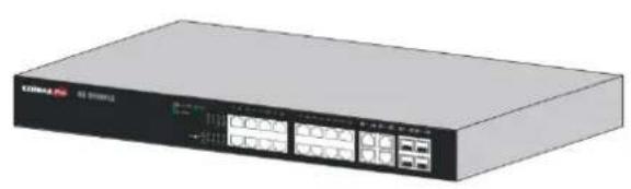
natural_image
Exterior view of a network switch device (no visible text or symbols)
2
- GS-5416PLC Switch OR
GS-5424PLC Switch
or
1
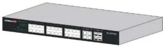
natural_image
Exterior view of a network switch device (no visible text or symbols)
3
-
Power Cord
-
Rack-Mount Kit & Screws
I-3 Features
● Supports up to 24 10/100/1000Mbps Gigabit Ethernet ports and 4 SFP slots or 4 mini-GBIC/SFP slots
- IEEE 802.3af/at PoE compliant to simplify deployment and installation
GS-5416PLC supports PoE up to 30W per port with 330W total power budget. Available PoE power output budget is 280W
GS-5424PLC supports PoE up to 30W per port with 450W total power budget. Available PoE power output budget is 400W
● Automacally detects powered devices (PD) and power consumpon levels
- IEEE 802.1Q VLAN for network segmentaon to enhance performance and security
● Supports Access Control List (ACL)
● Switch capacity: PG28CB: 56Gbps, Forwarding rate: 41.6Mbps
● Supports IGMP Snooping V1 / V2 / V3
● 8K MAC address table and 10K jumbo frames
● 19-inch rack-mountable metal case
I-4 Product Components
I-4-1 Ports
The following are the front views of the switches.

text_image
EDIMAX Pro 1 2 GS-5424PLCFigure 1 – GS-5424PLC Front View

text_image
EDIMAX Pro GS-5416PLC 1 2Figure 2 – GS-5416PLC Front View
| No. | Name | Descripon |
| 1 | 10/100/1000Mbps RJ-45 ports 1-24 for GS-5424PLC 1-16 for GS-5416PLC | Designed to connect to network devices with a bandwidth of 10Mbps, 100Mbps or 1000Mbps. Each has a corresponding 10/100/1000Mbps LED. |
| 2 | RJ45/SFP combo Ports (SFP1, SFP2, SFP3, and SFP4) | Designed to install SFP modules or RJ-45 connect to network devices with a bandwidth of 1000Mbps. Each has a corresponding 1000Mbps LED. |
The following is the rear view of the switches:

text_image
AC LINE 100-240 VAC 50/60 HzFigure 3 - Rear View
| No. | Name | Descripon |
| 1 | AC power in | Support AC100 – 240V 50-60Hz. |
I-4-2 LED Indicators
The following are the front views of the switches.

text_image
EDIMAX Pro 1 2 3 4 5 GS-5424PLCFigure 4 – GS-5424PLC Front View LED Indicators

text_image
EDIMAX Pro GS-5418PLC 1 2 3 4 5 100M PNC 100M 1P A1 2P A2 3P A3 4P A4 5P A5 6P A7 8P A9 10P A11 12P A13 14P A15 16P A17 18P A19 1A20 1A21 1A22 1A23 1A24 1A25 1A26 1A27 1A28 1A29 1A30 1A31 1A32 1A33 1A34 1A35 1A36 1A37 1A38 1A39 1A40Figure 5 – GS-5416PLC Front View LED Indicators
| No. | Name | Descripon |
| 1 | Power | ● O: power o● On: power on |
| 2 | System | ● O: system not ready● On: system ready● Blinking: system boot-up |
| 3 | PoE LED | ● O: PoE inacve● On: PoE acve |
| 4 | Port LED | ● O: port disconnected or link fail● Green on: 1000Mbs connected● Amber on: 10/100Mbs connected● Blinking: sending or receiving data |
| 5 | Combo Port LED | ● O: port disconnected or link fail● Green on: 1000Mbs connected |
This chapter describes how to install and connect your Edimax Switch. Read the following topics and perform the procedures in the correct order. Incorrect installation may cause damage to the product.
Please note, since the installaon / moung instrucons for dierent models of switches are almost identical, GS-5424PLC is used as the graphical demonstrates here.
II-1 Mounng the Switch
There are two ways to physically set up the switch.
- Place the switch on a at surface.
- Mount the switch in a standard rack (1 rack unit high).
II-1-1 Placement Tips
- Ambient Temperature — To prevent the switch from overheang, do not operate it in an area that exceeds an ambient temperature of 122^ ( 50^ ).
● Air Flow — Be sure that there is adequate air ow around the switch. - Mechanical Loading — Be sure that the switch is level and stable to avoid any hazardous conditions.
- Circuit Overloading — Adding the switch to the power outlet must not overload that circuit.
Follow these guidelines to install the switch securely.
● Put the switch in a stable place such as a desktop, to avoid it falling.
- Ensure the switch works in the proper AC input range and matches the voltage labeled.
- Ensure there is proper heat dissipion from and adequate venlaon around the switch.
- Ensure the switch's locaon can support the weight of the switch and its accessories.
II-1-2 Desktop Mounng
Please install the four rubber feet (included) on the boom of the switch and place the switch at the desired locaon.

natural_image
Illustration of a Max Pro network switch device (no text or symbols on the device body)Figure 6 - Desktop Installaon
II-1-3 Rack Mounng
You can mount the switch in any standard size, 19-inch (about 48 ~cm ) wide rack. The switch requires 1 rack unit (RU) of space, which is 1.75 inches ( 44.45 ~mm ) high.
For stability, load the rack from the boom to the top, with the heaviest devices on the boom. A top-heavy rack is likely to be unstable and may p over.
When mounng smaller switch products into a standard 19-inch rack, a pair of extension brackets (somemes referred to as ears) are needed to adapt the switch to the rack size.
These extension brackets are mounted on the switch using the screws provided in the kit, and have two holes that are used to then screw the switch into the rack.
An example of one type of these extension brackets is shown in the following gure.
A common problem that occurs during rack moung is the distance between the screw holes on the rack. Some racks are made with a uniform distance between all of the holes, and others have the holes organized into groups (see photo on the next page for an example).
When organized into groups, the switch must be placed in the rack so that the holes in the extension brackets line up correctly.
- Align the moung brackets with the moung holes on the switch's side panels and secure the brackets with the screws provided.

natural_image
Exterior view of a network equipment unit labeled EDIMAX Pro, showing ports and connectors (no readable text beyond branding)Figure 7 - Rack Mounng – Bracket Installaon
- Secure the switch on the equipment rack with the screws provided.

text_image
CDI/Max Pro CDI-5424PLCFigure 8 - Rack Mounng - Rack Installaon
This secon provides an introducon to the web-based conguraon ulity, and covers the following topics:
● Powering on the device
- Connecng to the network
● Power over Ethernet (PoE) consideraons
- Starng the web-based conguraon ulity
III-1 Connecng to Power
Power down and disconnect the power cord before servicing or wiring a switch.
Do not disconnect modules or cabling unless the power is rst switched o. The device only supports the voltage outlined in the type plate. Do not use any other power components except those specifically designated for the switch.
Disconnect the power cord before installaon or cable wiring.
The switch is powered by the AC 100-240 V 50/60Hz internal high-performance power supply. It is recommended to connect the switch with a single-phase three-wire power source with a neutral outlet, or a multifunctional computer professional source.
Connect the AC power connector on the back panel of the switch to the external power source with the included power cord, and check the power LED is on.

text_image
AC LINE 100-240 VAC 50/60 HzFigure 9 - Rear View AC Power Socket
III-2 Connecng to Network
To connect the switch to the network:
- Connect an Ethernet cable to the Ethernet port of a computer
- Connect the other end of the Ethernet cable to one of the numbered Ethernet ports of the switch. The LED of the port lights if the device connected is acve.
- Repeat Step 1 and Step 2 for each device to connect to the switch.
We strongly recommend using CAT-5E or beer cable to connect network devices. When connecng network devices, do not exceed the maximum cabling distance of 100 meters (328 feet). It can take up to one minute for aached devices or the LAN to be operational aer it is connected. This is normal behavior.
Connect the switch to end nodes using a standard Cat 5/5e Ethernet cable (UTP/STP) to connect the switch to end nodes as shown in the illustraon below.
Switch ports will automatically adjust to the characteriscs (MDI/MDI-X, speed, duplex) of the device to which the switch is connected.
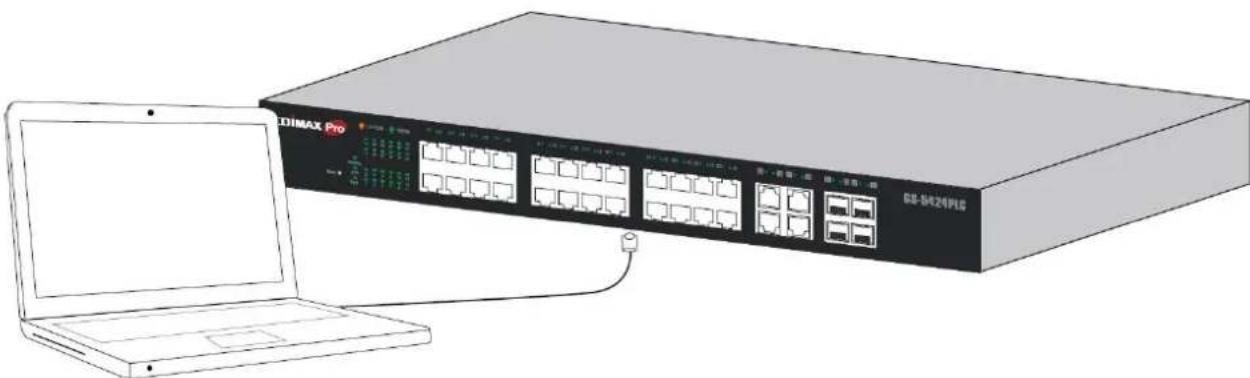
natural_image
Illustration of a DIMAX Pro network switch device connected to a laptop (no text or symbols on the device body)Figure 10 - PC Connect
III-3 Power over Ethernet (PoE) Consideraons
Devices considered a Power Sourcing Equipment (PSE), can support up to 30 Was per PoE port to a Powered Device (PD).
| Model | Power Dedicated to PoE | PoE Ports | PoE Standard Supported |
| GS-5416PLC | 280W | 1 to 16 | IEEE802.3at/af |
| GS-5424PLC | 400W | 1 to 24 | IEEE802.3at/af |
Ports 1-16 of GS-5416PLC and ports 1-24 of GS-5424PLC provide PoE power supply functionality with a maximum output power up to 30W each port. This can supply power to PDs such as internet phones, network cameras, wireless access points. Connect the switch PoE port directly to the PD port using a network cable.
When connecng switches capable of supplying PoE, consider the following informaon:
- Switch models with PoE funcon are PSEs. These models are capable of supplying DC power to aached PDs, such as VoIP phones, IP cameras, and wireless access points (APs). PoE switches. Additionally, PoE switches are capable of detectcng and supplying power to pre-standard legacy PoE Power Devices. Due to the support for legacy PoE, there is a possibility that PoE switches acng as a PSE may inadvertently detect and supply power an aached PSE, including other PoE switches. This false detecon may result in a PoE switch operang improperly and unable to supply power to aached PDs.
- The prevenon of a false detecon can be easily remedied by disabling PoE on the ports that are used to connect PSEs. Another simple pracce to prevent a false detecon is to rst power up a PSE device before connecng it to a PoE switch.
- When a device is falsely detected as a PD, disconnect the device from the PoE port and power recycle the device with AC power before reconnecting it to the PoE port.
III-4 Starng the Web-based Conguraon Utility
This secon describes how to navigate the web-based switch conguraon ulity. Be sure to disable any pop-up blocker.
Browser Restricons
- If you are using older versions of Internet Explorer, you cannot directly use an IPv6 address to access the device. You can, however, use the DNS (Domain Name System) server to create a domain name that contains the IPv6 address, and then use that domain name in the address bar in place of the IPv6 address.
- If you have mulple IPv6 interfaces on your management staon, use the IPv6 global address instead of the IPv6 link local address to access the device from your browser.
Launching the Conguraon Utility
To open the web-based conguraon ulity:
- Open a Web browser.
- Enter the IP address of the device you are conguring in the address bar on the browser (factory default IP address is 192.168.2.1) and then press Enter.
When the device is using the factory default IP address, its power LED ashes connuously. When the device is using a DHCP assigned IP address or an administrator-congured stac IP address, the power LED is lit a solid color. Your computer's IP address must be in the same subnet as the switch. For example, if the switch is using the factory default IP address, your computer's IP address can be in the following range: 192.168.2.x (whereas x is a number from 2 to 254).
Aer a successful conncon, the login window displays.

text_image
ESIMAX Pro Model Name GS-5424PLC Username: Password: Language English LOGINFigure 11 - GS-5416PLC Login Window

text_image
EDIMAX Pro Model Name GS-5416PLC Username: Password: Language English LOGINFigure 12 - GS-5416PLC Login Window
Please note that, unless otherwise specied, pictures / interfaces of GS-5424PLC will be used hereaer in the document.
III-4-1 Logging In
Note: Unless otherwise specied, pictures / interfaces of GS-5424PLC will be used hereaer in the document.
The default username is admin and the default password is 1234. The rst me that you log in with the default username and password, you are required to enter a new password.
To log in to the device conguraon ulity:
- Enter the default user ID (admin) and the default password (1234).
- If this is the rst me that you logged on with the default user ID (admin) and the default password (1234) it is recommended that you change your password immediately. See IV-14 Management on page 186 for additional informaon.
When the login aempt is successful, the System Informaon window displays.

text_image
EDIMAX Pro GS-5424PLC 24-Port Gigabit PoE+ Smart Managed Switch with 4 RJ45/SFP Combo Ports Save | Logout | Reboot Status >> System Information ► Status System Information Logging Message ► Port Link Aggregation MAC Address Table ► Network ► Port ► PoE ► VLAN ► MAC Address Table ► Spanning Tree ► Discovery ► Multicast ► Security ► ACL ► QoS ► Diagnostics ► Management EDIMAX Pro 2 4 6 8 10 12 14 16 18 20 22 24 26 28 26 28 1 3 5 7 9 11 13 15 17 19 21 23 25 27 25 27 System Information Edit Model GS-5424PLC System Name Switch System Location Default System Contact Default MAC Address 74:DA:38:17:6E:7A IPv4 Address 192.168.2.1 IPv6 Address fe80::76da:38fffe17:6e7a/64 System OID 1.3.6.1.4.1.27282.3.2.10 System Uptime 0 day, 0 hr, 1 min and 24 sec Current Time 2000-01-01 00:01:24 UTC+8 Loader Version 2.1.3.46351 Loader Date Sep 05 2017 - 20:22:00 Firmware Version 1.00.07 Firmware Date Nov 21 2017 - 14:54:59 Telnet Disabled SSH Disabled HTTP Enabled HTTPS Disabled SNMP EnabledFigure 13 - System Informaon
If you entered an incorrect username or password, an error message appears and the Login page remains displayed on the window. If you are having problems logging in, please see the Launching the Conguraon Ulity secon in the Administraon Guide for additional informaon.
III-4-2 Logging Out
By default, the applicaon logs out aer ten minutes of inactivity.
To manually logout, click Logout in the top right corner of any page.
When a meout occurs or you intenonally log out of the system, a message appears and the Login page appears, with a message indicang the logged-out state. Aer you log in, the applicaon returns to the initial page.
The PoE smart switch soware provides rich Layer 2 funconality for switches in your networks. This chapter describes how to use the web-based management interface (Web UI) to congregate the switch's features.
For the purposes of this manual, the user interface is separated into four seconds, as shown in the following gure:

text_image
EDiMAX Pro GS-5424PLC 24-Port Gigabit PoE+ Smart Managed Switch with 4 RJ45/SFP Combo Ports Save | Logout | Reboot Status >> System Information Status System Information Logging Message Port Link Aggregation MAC Address Table Network Port PoE VLAN MAC Address Table Spanning Tree Discovery Multicast Security ACL QoS Diagnostics Management 1 2 4 6 8 10 12 14 16 18 20 22 24 26 28 26 28 3 EDiMAX Pro 2 4 6 8 10 12 14 16 18 20 22 24 26 28 26 28 1 3 5 7 9 11 13 15 17 19 21 23 25 27 25 27 Edit System Information Edit Model GS-5424PLC System Name Switch System Location Default System Contact Default MAC Address 74:DA:38:17:6E:7A IPv4 Address 192.168.2.1 IPv6 Address fe80:76da:38ff:fe17:6e7a/64 System OID 1.3.6.1.4.1.27282.3.2.10 System Uptime 0 day, 0 hr, 1 min and 24 sec Current Time 2000-01-01 00:01:24 UTC+8 Loader Version 2.1.3.46351 Loader Date Sep 05 2017 - 20:22:00 Firmware Version 1.00.07 Firmware Date Nov 21 2017 - 14:54:59 Telnet Disabled SSH Disabled HTTP Enabled HTTPS Disabled SNMP EnabledFigure 14 - User Interface
| No. | Name | Descripon |
| 1 | Conguraon menu | Navigate to locate specic switch funcons. |
| 2 | Conguraon sengs | Edit specic funcon sengs. |
| 3 | Switch’s current link status | Green squares indicate the port link is up, while black squares indicate the port link is down. |
| 4 | Common toolbar | Provides access to frequently used sengs. |
IV-1 Status
Use the Status pages to view system informaon and status.
IV-1-1 System Informaon
This page shows switch panel, CPU ulizaon, Memory ulizaon and other system current informaon. It also allows user to edit some system informaon.
To display the Device Informaon web page, click Status > System Informaon.
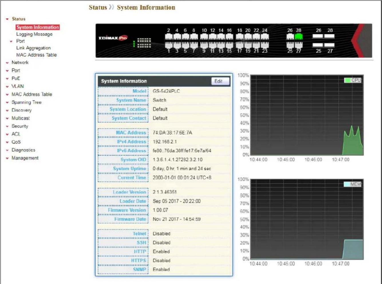
text_image
Status >> System Information ► Status System Information Logging Message ► Port Link Aggregation MAC Address Table ► Network ► Port ► PoE ► VLAN ► MAC Address Table ► Spanning Tree ► Discovery ► Multicast ► Security ► ACL ► GoS ► Diagnostics ► Management EDIMAX Pro 2 4 6 8 10 12 14 16 18 20 22 24 26 28 26 28 1 3 5 7 9 11 13 15 17 19 21 23 25 27 25 27 System Information Edit Model GS-5424PLC System Name Switch System Location Default System Contact Default MAC Address 74:DA:38:17.6E:7A IPv4 Address 192.168.2.1 IPv6 Address fe80..76da:30ff.fe17.6e7a/64 System OID 1.3.6.1.4.1.27282.3.2.10 System Uptime 0 day, 0 hr, 1 min and 24 sec Current Time 2000-01-01 00:01:24 UTC+8 Loader Version 2.1.3.46351 Loader Date Sep 05 2017 - 20:22:00 Firmware Version 1.00.07 Firmware Date Nov 21 2017 - 14:54:59 Telnet Disabled SSH Disabled HTTP Enabled HTTPS Disabled SNMP EnabledFigure 15 - Status > System Informaon
| Item | Descripon |
| Model | Model name of the switch. |
| System Name | System name of the switch. This name will also use as CLI prex of each line. (“Switch>” or “Switch#”). |
| System Locaon | Locaon informaon of the switch. |
| System Contact | Contact informaon of the switch. |
| MAC Address | Base MAC address of the switch. |
| IPv4 Address | Current system IPv4 address. |
| System OID | SNMP system object ID. |
| System Upme | Total elapsed me from boong. |
| Current Time | Current system me. |
| Loader Version | Boot loader image version. |
| Loader Date | Boot loader image build date. |
| Firmware Version | Current running rmware image version. |
| Firmware Date | Current running rmware image build date. |
| Telnet | Current Telnet service enable/disable state. |
| SSH | Current SSH service enable/disable state. |
| HTTP | Current HTTP service enable/disable state. |
| HTTPS | Current HTTPS service enable/disable state. |
| SNMP | Current SNMP service enable/disable state. |
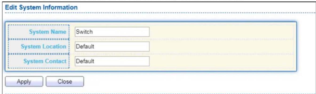
Click "Edit" buon on the table tle to edit following system informaon.
text_image
Edit System Information System Name Switch System Location Default System Contact Default Apply CloseFigure 16 - Status > System Informaon > Edit System Informaon
| Item | Descripon |
| System Name | System name of the switch. This name will also use as CLI prex of each line. (“Switch>” or “Switch#”). |
| System Locaon | Locaon informaon of the switch. |
| System Contact | Contact informaon of the switch. |
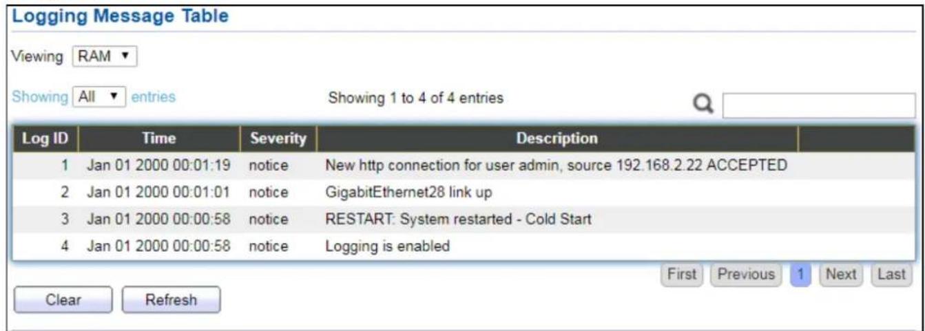
IV-1-2 Logging Message
To view the logging messages stored on the RAM and Flash, click Status > Logging Message.
text_image
Logging Message Table Viewing RAM ▼ Showing All ▼ entries Showing 1 to 4 of 4 entries Log ID Time Severity Description 1 Jan 01 2000 00:01:19 notice New http connection for user admin, source 192.168.2.22 ACCEPTED 2 Jan 01 2000 00:01:01 notice GigabitEthernet28 link up 3 Jan 01 2000 00:00:58 notice RESTART: System restarted - Cold Start 4 Jan 01 2000 00:00:58 notice Logging is enabled Clear Refresh First Previous 1 Next LastFigure 17 - Status > Logging Message
| Item | Descripon |
| Log ID | The log idener. |
| Time | The me stamp for the logging message. |
| Severity | The severity for the logging message. |
| Descripon | The descripon of logging message. |
| Viewing | The logging view including:● RAM: Show the logging messages stored on the RAM.● Flash: Show the logging messages stored on the Flash. |
| Clear | Clear the logging messages. |
| Refresh | Refresh the logging messages. |
IV-1-3 Port
IV-1-3-1 Stascs
This page displays standard counters on network trac form the Interfaces, Ethernet-like and RMONMIB. Interfaces and Ethernet-like counters display errors on the trac passing through each port. RMON counters provide a total count of dierent frame types and sizes passing through each port. The “Clear” buon will clear MIB counter of current selected port.
To display the Port Flow Chart web page, click Status > Port > Stascs.

text_image
Port GE1 MIB Counter All Interface Etherlike RMON Refresh Rate None 5 sec 10 sec 30 sec
| Interface | |
| ifInOctets | 0 |
| ifInUcastPkts | 0 |
| ifInNUcastPkts | 0 |
| ifInDiscards | 0 |
| ifOutOctets | 0 |
| ifOutUcastPkts | 0 |
| ifOutNUcastPkts | 0 |
| ifOutDiscards | 0 |
| ifInMulticastPkts | 0 |
| ifInBroadcastPkts | 0 |
| ifOutMulticastPkts | 0 |
| ifOutBroadcastPkts | 0 |
| Etherlike | |
| dot3StatsAlignmentErrors | 0 |
| dot3 StatsFCSErrors | 0 |
| dot3 Stats SingleCollisionFrames | 0 |
| dot3 StatsMultipleCollisionFrames | 0 |
| dot3 StatsDeferredTransmissions | 0 |
| dot3 StatsLateCollisions | 0 |
| dot3 StatsExcessiveCollisions | 0 |
| dot3StatsSymbolErrors | 0 |
| dot3ControllUnknownOpcodes | 0 |
| dot3InPauseFrames | 0 |
| dot3OutPauseFrames | 0 |
| RMON | |
| etherStatsDropEvents | 0 |
| etherStatsOctets | 0 |
| etherStatsPkts | 0 |
| etherStatsBroadcastPkts | 0 |
| etherStatsMulticastPkts | 0 |
| etherStatsCRCAlignErrors | 0 |
| etherStatsUnderSizePkts | 0 |
| etherStatsOverSizePkts | 0 |
| etherStatsFragments | 0 |
| etherStatsJabbers | 0 |
| etherStatsCollisions | 0 |
| etherStatsPkts64Octets | 0 |
| etherStatsPkts65to127Octets | 0 |
| etherStatsPkts128to255Octets | 0 |
| etherStatsPkts256to511Octets | 0 |
| etherStatsPkts512to1023Octets | 0 |
| etherStatsPkts1024to1518Octets | 0 |
Figure 18 - Status > Port > Stascs
| Item | Descripon |
| Port | Select one port to show counter stascs. |
| MIB Counter | Select the MIB counter to show dierent counter type● All: All counters.● Interface: Interface related MIB counters.● Etherlike: Ethernet-like related MIB counters.● RMON: RMON related MIB counters. |
| Refresh Rate | Refresh the web page every period of seconds to get new counter of specied port. |
IV-1-3-2 Error Disabled
To display the Error Disabled web page, click Status > Port > Error Disabled.
| Port | Reason | Time Left (sec) |
| GE1 | --- | --- |
| GE2 | --- | --- |
| GE3 | --- | --- |
| GE4 | --- | --- |
| GE5 | --- | --- |
| GE6 | --- | --- |
| GE7 | --- | --- |
| GE8 | --- | --- |
| GE9 | --- | --- |
| GE10 | --- | --- |
| GE11 | --- | --- |
| GE12 | --- | --- |
| GE13 | --- | --- |
| GE14 | --- | --- |
| GE15 | --- | --- |
| GE16 | --- | --- |
| GE17 | --- | --- |
| GE18 | --- | --- |
| GE19 | --- | --- |
| GE20 | --- | --- |
| GE21 | --- | --- |
| GE22 | --- | --- |
| GE23 | --- | --- |
| GE24 | --- | --- |
| GE25 | --- | --- |
| GE26 | --- | --- |
| GE27 | --- | --- |
| GE28 | --- | --- |
| LAG1 | --- | --- |
| LAG2 | --- | --- |
| LAG3 | --- | --- |
Figure 19 - Status > Port > Error Disabled
| Item | Descripon |
| □ | Select one or more port to operate. |
| Port | Interface or port number. |
| Reason | Port will be disabled by one of the following error reason:BPDU GuardUDLDSelf LoopBroadcast FloodUnknown Mulcast FloodUnicast FloodACL● Port Security Violaon● DHCP rate limit● ARP rate limit |
| Time Le (sec) | The me le in second for the error recovery. |
| Refresh | Refresh the current page. |
| Recover | Recover the selected port status. |
IV-1-3-3 Bandwidth Ulizaon
This page allows user to browse ports' bandwidth ulizaon in real me. This page will refresh automacally in every refresh period.
To display Bandwidth Ulizaon web page, click Status > Port > Bandwidth Ulizaon.

bar
| Channel | Refresh Rate (sec) | Link Down (%) | | :--- | :--- | :--- | | GE28 | 1000 | Link Down | | GE28 | 1000 | Link Down | | GE27 | 1000 | Link Down | | GE26 | 1000 | Link Down | | GE25 | 1000 | Link Down | | GE24 | 1000 | Link Down | | GE23 | 1000 | Link Down | | GE22 | 1000 | Link Down | | GE21 | 1000 | Link Down | | GE20 | 1000 | Link Down | | GE19 | 1000 | Link Down | | GE18 | 1000 | Link Down | | GE17 | 1000 | Link Down | | GE16 | 1000 | Link Down | | GE15 | 1000 | Link Down | | GE14 | 1000 | Link Down | | GE13 | 1000 | Link Down | | GE12 | 1000 | Link Down | | GE11 | 1000 | Link Down | | GE10 | 1000 | Link Down | | GE9 | 1000 | Link Down | | GE8 | 1000 | Link Down | | GE7 | 1000 | Link Down | | GE6 | 1000 | Link Down | | GE5 | 1000 | Link Down | | GE4 | 1000 | Link Down | | GE3 | 1000 | Link Down | | GE2 | 1000 | Link Down | | GE1 | 1000 | Link Down | Transmit (%): 65% - 65%, Receive (%): 45% - 65%.Figure 20 - Status > Port > Bandwidth Ulizaon
| Item | Descripon |
| Refresh Rate | Refresh the web page every period of seconds to get new bandwidth ulizaon data. |
IV-1-4 Link Aggregaon
To display the Link Aggregaon web page, click Status > Link Aggregaon.
| LAG | Name | Type | Link Status | Active Member | Inactive Member | |
| LAG 1 | --- | --- | ||||
| LAG 2 | --- | --- | ||||
| LAG 3 | --- | --- | ||||
| LAG 4 | --- | --- | ||||
| LAG 5 | --- | --- | ||||
| LAG 6 | --- | --- | ||||
| LAG 7 | --- | --- | ||||
| LAG 8 | --- | --- |
Figure 21 - Status > Link Aggregaon
| Item | Descripon |
| LAG | LAG Name. |
| Name | LAG port descripon. |
| Type | The type of the LAG.● Stac: The group of ports assigned to a stac LAG are always acve members.● LACP: The group of ports assigned to dynamic LAG are candidate ports. LACP determines which candidate ports are acve member ports. |
| Link Status | LAG port link status. |
| Acve Member | Acve member ports of the LAG. |
| Inacve Member | Inacve member ports of the LAG. |
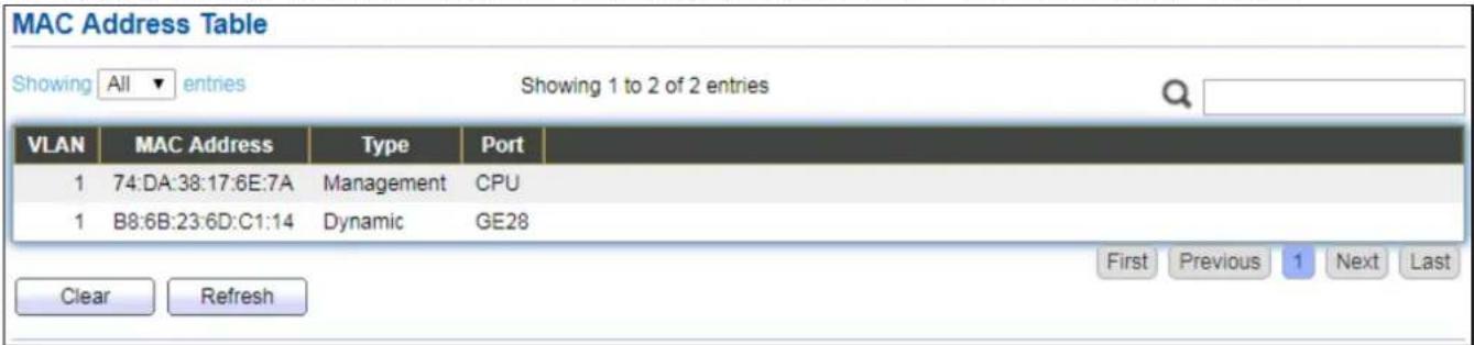
IV-1-5 MAC Address Table
The MAC address table page displays all MAC address entries on the switch including stac MAC address created by administrator or auto learned from hardware. The “Clear” buon will clear all dynamic entries and “Refresh” buon will retrieve latest MAC address entries and show them on page.
To display the MAC Address Table web page, click Status > MAC Address Table.
text_image
MAC Address Table Showing All entries Showing 1 to 2 of 2 entries VLAN MAC Address Type Port 1 74:DA:38:17:6E:7A Management CPU 1 B8:6B:23:6D:C1:14 Dynamic GE28 Clear Refresh First Previous 1 Next LastFigure 22 - Status > MAC Address Table
| Item | Descripon |
| VLAN | VLAN ID of the mac address. |
| MAC Address | MAC address. |
| Type | The type of MAC addressManagement: DUT's base mac address for management Purpose.Stac: Manually congured by administratorDynamic: Auto learned by hardware. |
| Port | The type of PortCPU: DUT's CPU port for management purpose.Other: Normal switch port. |
IV-2 Network
Use the Network pages to congregate sengs for the switch network interface and how the switch connects to a remote server to get services.
IV-2-1 IP Address
This secon allows you to edit the IP address, Netmask, Gateway and DNS server of the switch.
To view the IP Address menu, navigate to Network > IP Address.

text_image
IPv4 Address Address Type Static Dynamic IP Address 192.168.2.1 Subnet Mask 255.255.255.0 Default Gateway 192.168.2.254 DNS Server 1 168.95.1.1 DNS Server 2 168.95.192.1 IPv6 Address Auto Configuration Enable DHCPv6 Client Enable IPv6 Address Prefix Length: 0 (0 - 128) IPv6 Gateway DNS Server 1 DNS Server 2 Operational Status IPv4 Address 192.168.2.1 IPv4 Default Gateway 192.168.2.254 IPv6 Address fe80::76da:38ff:fe17:6e7a/64 IPv6 Gateway : Link Local Address fe80::76da:38ff:fe17:6e7a/64 ApplyFigure 23 - Network > IP Address
| Item | Descripon |
| Address Type | The address type of switch IP conguraon including● Stac: Stac IP congured by users will be used.● Dynamic: Enable the DHCP to obtain the IP address from a DHCP server. |
| IP Address | Specify the switch stac IP address on the stac conguraon. |
| Subnet Mask | Specify the switch subnet mask on the stac conguraon. |
| Default Gateway | Specify the default gateway on the stac conguraon. Thedefault gateway must be in the same subnet with switch IP address conguraon. |
| DNS Server 1 | Specify the primary user-dened IPv4 DNS server conguraon. |
| DNS Server 2 | Specify the secondary user-dened IPv4 DNS server conguraon. |
| Table 3-2: IPv6 Address elds | |
| IPv4 Address | The operaonal IPv4 address of the switch. |
| IPv4 Gateway | The operaonal IPv4 gateway of the switch. |
| IPv6 Address v6 | The operaonal IPv6 address of the switch. |
| IPv6 Gateway | The operaonal IPv6 gateway of the switch. |
| Link Local Address | The IPv6 link local address for the switch. |
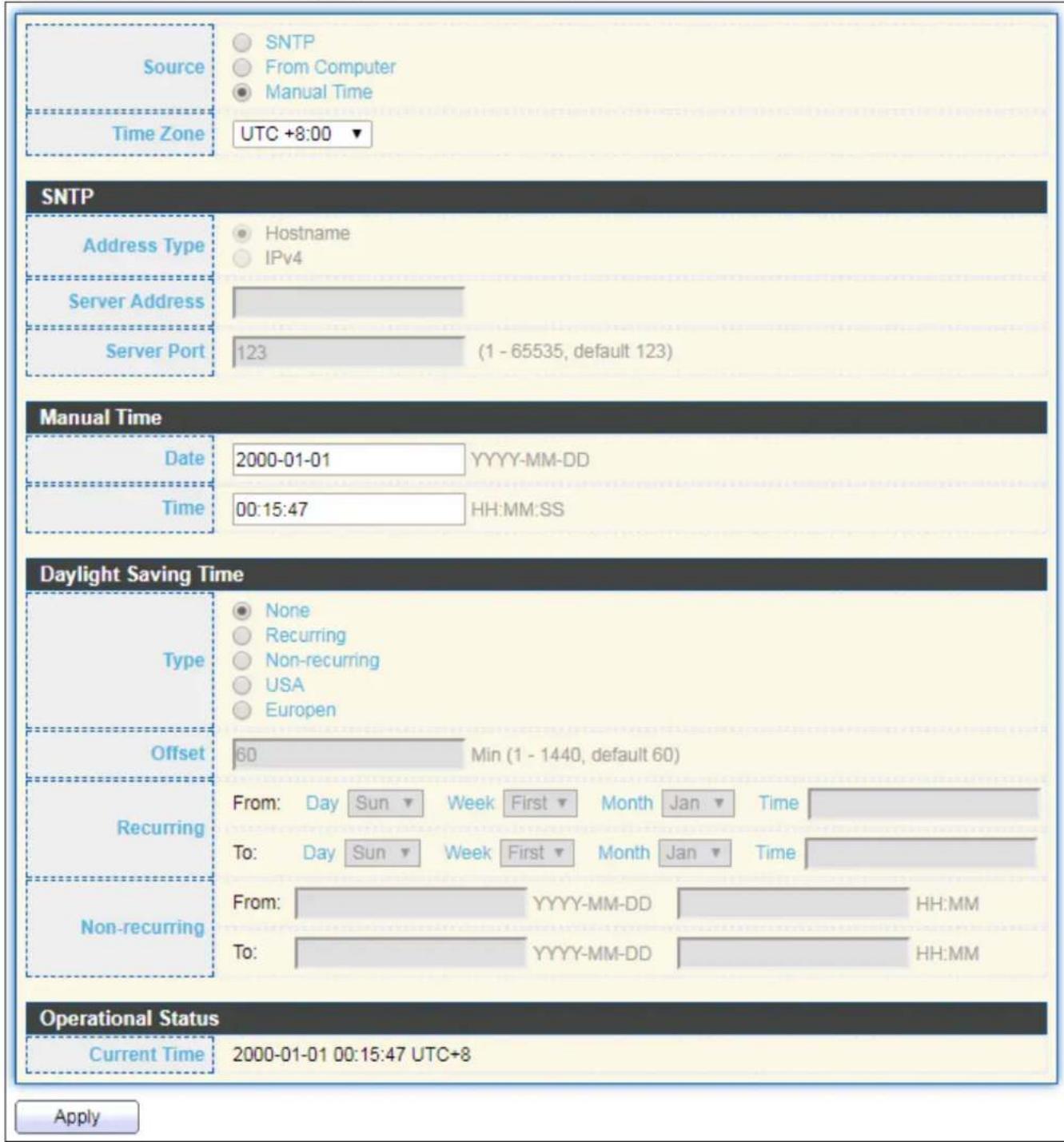
IV-2-2 System Time
This page allows user to set me source, stac me, me zone and daylight saving sengs. Time zone and daylight saving takes eect both stac me or me from SNTP server.
To display System Time page, click Network > System Time.
text_image
Source Time Zone SNTP From Computer Manual Time UTC +8:00 SNTP Address Type Hostname IPv4 Server Address Server Port 123 (1 - 65535, default 123) Manual Time Date 2000-01-01 YYYY-MM-DD Time 00:15:47 HH:MM:SS Daylight Saving Time Type None Recurring Non-recurring USA Europen Offset 60 Min (1 - 1440, default 60) Recurring From: Day Sun Week First Month Jan Time To: Day Sun Week First Month Jan Time Non-recurring From: YYYY-MM-DD HH:MM To: YYYY-MM-DD HH:MM Operational Status Current Time 2000-01-01 00:15:47 UTC+8 ApplyFigure 24 - Network > System Time
| Item | Descripon |
| Source | Select the me source.● SNTP: Time sync from NTP server.● From Computer: Time set from browser host.● Manual Time: Time set by manually congure. |
| Time Zone | Select a me zone dience from lisng district. |
| SNTP | |
| Address Type | Select the address type of NTP server. This is enabled when me source is SNTP. |
| Server Address | Input IPv4 address or hostname for NTP server. This is enabled when me source is SNTP. |
| Server Port | Input NTP port for NTP server. Default is 123. This is enabled when me source is SNTP. |
| Manual Time | |
| Date | Input manual date. This is enabled when me source is manual. |
| Time | Input manual me. This is enabled when me source is manual. |
| Daylight Saving Time | |
| Type | Select the mode of daylight saving me.● Disable: Disable daylight saving me.● Recurring: Using recurring mode of daylight saving me.● Non-Recurring: Using non-recurring mode of daylight saving me.● USA: Using daylight saving me in the United States that starts on the second Sunday of March and ends on the rst Sunday of November.● European: Using daylight saving me in the Europe that starts on the last Sunday in March and ending on the last Sunday in October. |
| Oset | Specify the adjust oset of daylight saving me. |
| Recurring From | Specify the starng me of recurring daylight saving me. This eld available when selecng “Recurring” mode. |
| Recurring To | Specify the ending me of recurring daylight saving me. This eld available when selecng “Recurring” mode. |
| Non-recurring From | Specify the starng me of non-recurring daylight saving me. This eld available when selecng “Non-Recurring” mode. |
| Non-recurring To | Specify the ending me of recurring daylight saving me. This eld available when selecng “Non-Recurring” mode. |
| Non-recurring From | Specify the starng me of non-recurring daylight saving me. This eld available when selecng “Non-Recurring” mode. |
| Non recurring To | Specify the ending me of recurring daylight saving me. This eld available when selecng “Non-Recurring” mode. |
IV-3 Port
Use the Port pages to congregate sengs for switch port related features.
IV-3-1 Port Seng
This page shows port current status and allow user to edit port conguraons. Select port entry and click "Edit" buon to edit port conguraons.
To display Port Seng web page, click Port > Port Seng.
Port Setting Table
| Entry | Port | Type | Description | State | Link Status | Speed | Duplex | Flow Control |
| 1 | GE1 | 1000M Copper | Enabled | Down | Auto | Auto | Disabled | |
| 2 | GE2 | 1000M Copper | Enabled | Down | Auto | Auto | Disabled | |
| 3 | GE3 | 1000M Copper | Enabled | Down | Auto | Auto | Disabled | |
| 4 | GE4 | 1000M Copper | Enabled | Down | Auto | Auto | Disabled | |
| 5 | GE5 | 1000M Copper | Enabled | Down | Auto | Auto | Disabled | |
| 6 | GE6 | 1000M Copper | Enabled | Down | Auto | Auto | Disabled | |
| 7 | GE7 | 1000M Copper | Enabled | Down | Auto | Auto | Disabled | |
| 8 | GE8 | 1000M Copper | Enabled | Down | Auto | Auto | Disabled | |
| 9 | GE9 | 1000M Copper | Enabled | Down | Auto | Auto | Disabled | |
| 10 | GE10 | 1000M Copper | Enabled | Down | Auto | Auto | Disabled | |
| 11 | GE11 | 1000M Copper | Enabled | Down | Auto | Auto | Disabled | |
| 12 | GE12 | 1000M Copper | Enabled | Down | Auto | Auto | Disabled | |
| 13 | GE13 | 1000M Copper | Enabled | Down | Auto | Auto | Disabled | |
| 14 | GE14 | 1000M Copper | Enabled | Down | Auto | Auto | Disabled | |
| 15 | GE15 | 1000M Copper | Enabled | Down | Auto | Auto | Disabled | |
| 16 | GE16 | 1000M Copper | Enabled | Down | Auto | Auto | Disabled | |
| 17 | GE17 | 1000M Copper | Enabled | Down | Auto | Auto | Disabled | |
| 18 | GE18 | 1000M Copper | Enabled | Down | Auto | Auto | Disabled | |
| 19 | GE19 | 1000M Copper | Enabled | Down | Auto | Auto | Disabled | |
| 20 | GE20 | 1000M Copper | Enabled | Down | Auto | Auto | Disabled | |
| 21 | GE21 | 1000M Copper | Enabled | Down | Auto | Auto | Disabled | |
| 22 | GE22 | 1000M Copper | Enabled | Down | Auto | Auto | Disabled | |
| 23 | GE23 | 1000M Copper | Enabled | Down | Auto | Auto | Disabled | |
| 24 | GE24 | 1000M Copper | Enabled | Down | Auto | Auto | Disabled | |
| 25 | GE25 | 1000M Combo Copper | Enabled | Down | Auto | Auto | Disabled | |
| 26 | GE26 | 1000M Combo Copper | Enabled | Down | Auto | Auto | Disabled | |
| 27 | GE27 | 1000M Combo Copper | Enabled | Down | Auto | Auto | Disabled | |
| 28 | GE28 | 1000M Combo Copper | Enabled | Up | Auto (1000M) | Auto (Full) | Disabled (Disabled) |
Figure 25 - Port > Port Seng
| Item | Descripon |
| Port | Port Name. |
| Type | Port media type. |
| Descripon | Port Descripon. |
| State | Port admin state● Enabled: Enable the port.● Disabled: Disable the port. |
| Link Status | Current port link status● Up: Port is link up.● Down: Port is link down. |
| Speed | Current port speed conguraon and link speed status. |
| Duplex | Current port duplex conguraon and link duplex status. |
| Flow Control | Current port ow control conguraon and link ow control status. |
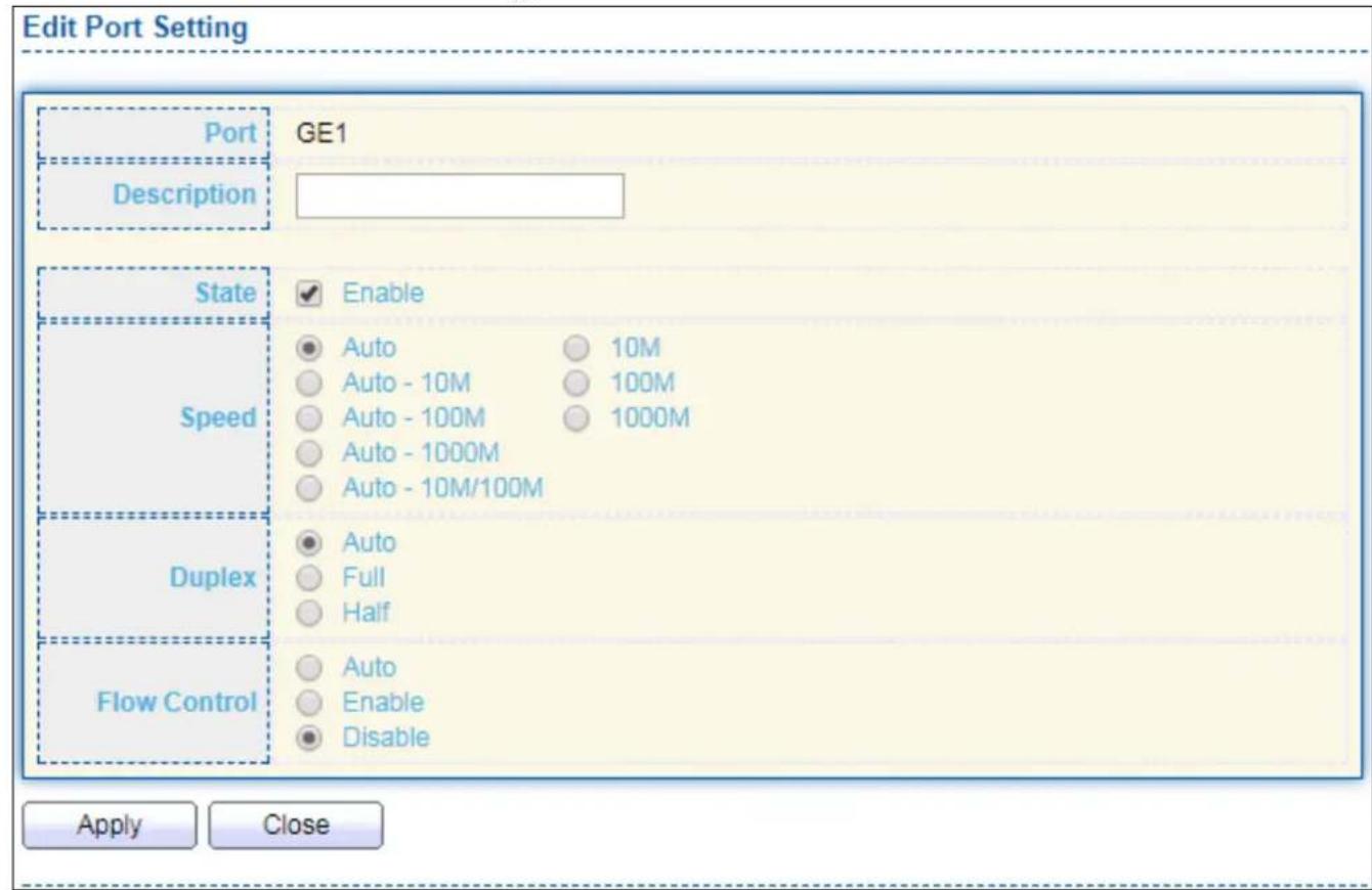
Click "Edit" buon to edit Port Seng menu
text_image
Edit Port Setting Port GE1 Description State Enable Speed Auto 10M Auto - 10M 100M Auto - 100M 1000M Auto - 1000M Auto - 10M/100M Duplex Auto Full Half Flow Control Auto Enable Disable Apply CloseFigure 26 - Port > Port Seng > Port Seng
| Item | Descripon |
| Port | Selected Port list. |
| Descripon | Port media type. |
| State | Port admin state.● Enabled: Enable the port.● Disabled: Disable the port. |
| Speed | Port speed capabilities.● Auto: Auto speed with all capabilities.● Auto-10M: Auto speed with 10M ability only.● Auto-100M: Auto speed with 100M ability only.● Auto-1000M: Auto speed with 1000M ability only.● Auto-10M/100M: Auto speed with 10M/100M abilities.● 10M: Force speed with 10M ability.● 100M: Force speed with 100M ability.● 1000M: Force speed with 1000M ability. |
| Duplex | Port duplex capabilities.● Auto: Auto duplex with all capabilities.● Half: Auto speed with 10M and 100M ability only.● Full: Auto speed with 10M/100M/1000M ability only. |
| Flow Control | Port ow control.● Auto: Auto ow control by negoaon.● Enabled: Enable ow control ability.● Disabled: Disable ow control ability. |
IV-3-2 Long Range Mode
This page shows port current status and Enable long range mode will double the cabling distance but reduce the speed to 10Mbps.
To display Long Range Mode web page, click Port > Long Range Mode Seng.
Long Range Mode Table
Enable long range mode will double the cabling distance but reduce the speed to 10Mbps.
| Port | State |
| GE1 | Disable ▼ |
| GE2 | Disable ▼ |
| GE3 | Disable ▼ |
| GE4 | Disable ▼ |
| GE5 | Disable ▼ |
| GE6 | Disable ▼ |
| GE7 | Disable ▼ |
| GE8 | Disable ▼ |
| GE9 | Disable ▼ |
| GE10 | Disable ▼ |
| GE11 | Disable ▼ |
| GE12 | Disable ▼ |
| GE13 | Disable ▼ |
| GE14 | Disable ▼ |
| GE15 | Disable ▼ |
| GE16 | Disable ▼ |
| GE17 | Disable ▼ |
| GE18 | Disable ▼ |
| GE19 | Disable ▼ |
| GE20 | Disable ▼ |
| GE21 | Disable ▼ |
| GE22 | Disable ▼ |
| GE23 | Disable ▼ |
| GE24 | Disable ▼ |
| GE25 | Disable ▼ |
| GE26 | Disable ▼ |
| GE27 | Disable ▼ |
| GE28 | Disable ▼ |
Apply
Figure 27 - Port > Long Range Mode
IV-3-3 Error Disable
To display Error Disabled web page, click Port > Error Disabled

text_image
Recovery Interval 300 Sec (30 - 86400) BPDU Guard Enable UDLD Enable Self Loop Enable Broadcast Flood Enable Unknown Multicast Flood Enable Unicast Flood Enable ACL Enable Port Security Enable DHCP Rate Limit Enable ARP Rate Limit Enable ApplyFigure 28 - Port > Error disable
| Item | Descripon |
| Recover Interval | Auto recovery aer this interval for error disabled port. |
| BPDU Guard | Enabled to auto shutdown port when BPDU Guard reason occur. This reason caused by STP BPDU Guard mechanism. |
| UDLD | Enabled to auto shutdown port when UDLD violaon occur. |
| Self Loop | Enabled to auto shutdown port when Self Loop reason occur. |
| Broadcast Flood | Enabled to auto shutdown port when Broadcast Flood reason occur. This reason caused by broadcast rate exceed broadcast storm control rate. |
| Unknown Mulcast Flood | Enabled to auto shutdown port when Unknown Mulcast Flood reason occur. This reason caused by unknown mulcast rate exceed unknown mulcast storm control rate. |
| Unicast Flood | Enabled to auto shutdown port when Unicast Flood reason occur. This reason caused by unicast rate exceed unicast storm control rate. |
| ACL | Enabled to auto shutdown port when ACL shutdown port reason occur. This reason caused packet match the ACL shutdown port acon. |
| Port Security | Enabled to auto shutdown port when Port Security Violaon reason occur. This reason caused by violaon port security rules. |
| DHCP rate limit | Enabled to auto shutdown port when DHCP rate limit reason occur. This reason caused by DHCP packet rate exceed DHCP rate limit. |
| ARP rate limit | Enabled to auto shutdown port when ARP rate limit reason occur.This reason caused by DHCP packet rate exceed ARP rate limit. |
IV-3-4 Link Aggregaon
IV-3-4-1 Group
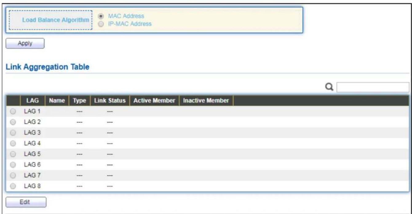
This page allows user to congregate link aggregaon group load balance algorithm and group member.
To view the Group menu, navigate to Port > Link Aggregaon > Group.
text_image
Load Balance Algorithm MAC Address IP-MAC Address Apply Link Aggregation Table LAG Name Type Link Status Active Member Inactive Member LAG 1 --- --- LAG 2 --- --- LAG 3 --- --- LAG 4 --- --- LAG 5 --- --- LAG 6 --- --- LAG 7 --- --- LAG 8 --- --- EditFigure 29 - Port > Link Aggregaon > Group
| Item | Descripon |
| Load Balance Algorithm | LAG load balance distribuon algorithm● src-dst-mac: Based on MAC address.● src-dst-mac-ip: Based on MAC address and IP address. |
| LAG | LAG Name. |
| Name | LAG port descripon. |
| Type | The type of the LAG● Stac: The group of ports assigned to a stac LAG are always acve members.● LACP: The group of ports assigned to dynamic LAG are candidate ports. LACP determines which candidate ports are acve member ports. |
| Link Status | LAG port link status |
| Acve Member | Acve member ports of the LAG. |
| Inacve Member | Inacve member ports of the LAG. |
Click "Edit" to edit Link Aggregaon Group menu.

text_image
Edit Link Aggregation Group LAG 1 Name Type Static LACP Member Available Port Selected Port GE1 GE2 GE3 GE4 GE5 GE6 GE7 GE8 Apply CloseFigure 30 - Port > Link Aggregaon > Group > Edit Link Aggregaon Group
| Item | Descripon |
| LAG | Selected LAG group ID. |
| Name | LAG port descripon. |
| Type | The type of the LAG● Stac: The group of ports assigned to a stac LAG are always acve members.● LACP: The group of ports assigned to dynamic LAG are candidate ports. LACP determines which candidate ports are acve member ports. |
| Member | Select available port to be LAG group member port. |
IV-3-4-2 Port Seng
This page shows LAG port current status and allow user to edit LAG port conguraons. Select LAG entry and click "Edit" buon to edit LAG port conguraons.
To display LAG Port Seng web page, click Port > Link Aggregaon > Port Setng.
| Port Setting Table | ||||||||
| LAG | Type | Description | State | Link Status | Speed | Duplex | Flow Control | |
| LAG 1 | Enabled | Down | Auto | Auto | Disabled | |||
| LAG 2 | Enabled | Down | Auto | Auto | Disabled | |||
| LAG 3 | Enabled | Down | Auto | Auto | Disabled | |||
| LAG 4 | Enabled | Down | Auto | Auto | Disabled | |||
| LAG 5 | Enabled | Down | Auto | Auto | Disabled | |||
| LAG 6 | Enabled | Down | Auto | Auto | Disabled | |||
| LAG 7 | Enabled | Down | Auto | Auto | Disabled | |||
| LAG 8 | Enabled | Down | Auto | Auto | Disabled | |||
Figure 31 - Port > Link Aggregaon > Port Seng
| Item | Descripon |
| LAG | LAG Port Name. |
| Type | LAG Port media type. |
| Descripon | LAG Port descripon. |
| State | LAG Port admin state● Enabled: Enable the port.● Disabled: Disable the port. |
| Link Status | Current LAG port link status● Up: Port is link up.● Down: Port is link down. |
| Speed | Current LAG port speed conguraon and link speed status. |
| Duplex | Current LAG port duplex conguraon and link duplex status. |
| Flow Control | Current LAG port ow control conguraon and link ow control status. |
Click "Edit" to view Edit Port Seng menu.
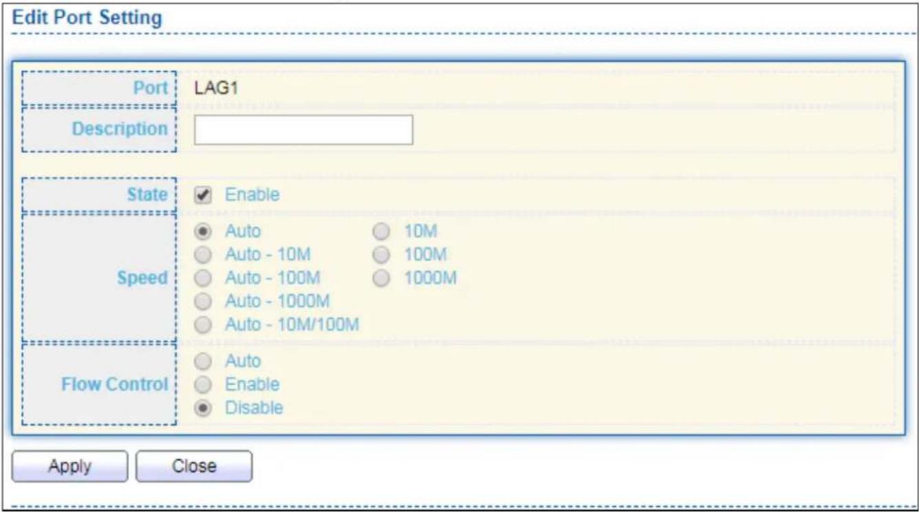
text_image
Edit Port Setting Port Description LAG1 State Speed Flow Control Apply Close Enable Auto Auto - 10M Auto - 100M Auto - 1000M Auto - 10M/100M 10M 100M 1000M Auto Auto Enable DisableFigure 32 - Port > Link Aggregaon > Port Seng > Edit Port Seng
| Item | Descripon |
| Port | Selected Port list. |
| Descripon | Port descripon. |
| State | Port admin state● Enabled: Enable the port.● Disabled: Disable the port. |
| Speed | Port speed capabilities● Auto: Auto speed with all capabilities.● Auto-10M: Auto speed with 10M ability only.● Auto-100M: Auto speed with 100M ability only.● Auto-1000M: Auto speed with 1000M ability only.● Auto-10M/100M: Auto speed with 10M/100M abilities.● 10M: Force speed with 10M ability.● 100M: Force speed with 100M ability.● 1000M: Force speed with 1000M ability. |
| Flow Control | Port ow control● Auto: Auto ow control by negoaon.● Enabled: Enable ow control ability.● Disabled: Disable ow control ability. |
IV-3-4-3 LACP
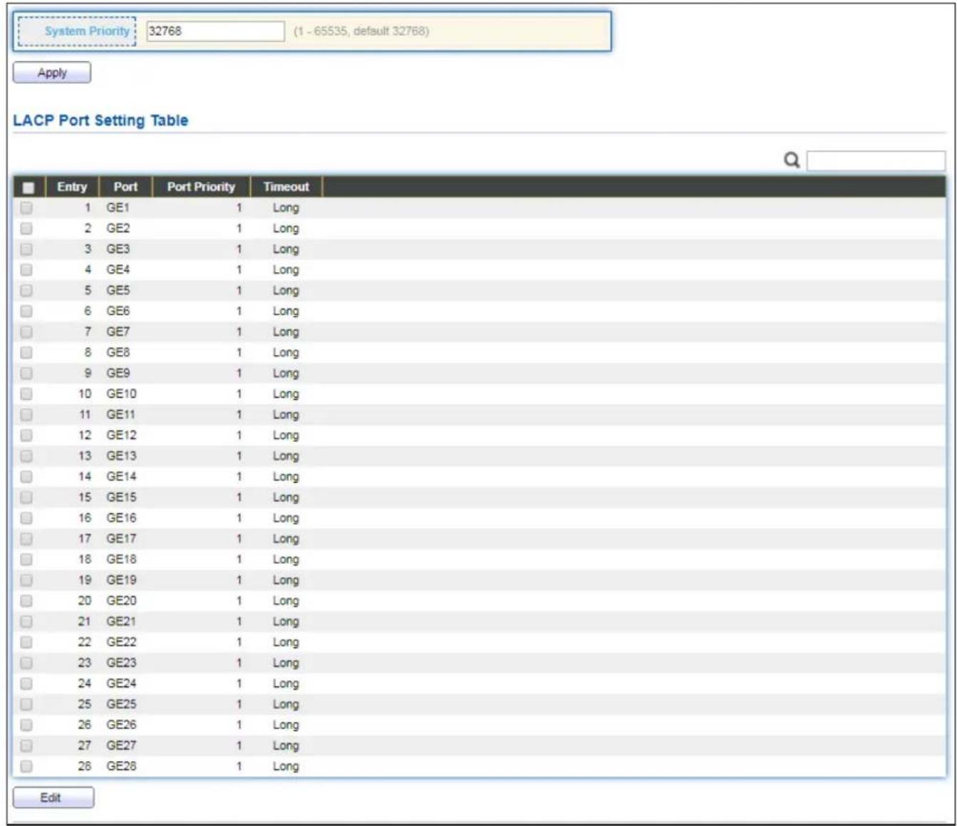
This page allows user to congregate LACP global and port conguraons. Select ports and click "Edit" buon to edit port conguraon.
To display the LACP Seng web page, click Port > Link Aggregaon > LACP.
text_image
System Priority: 32768 (1 - 65535, default 32768) Apply LACP Port Setting Table Entry Port Port Priority Timeout 1 GE1 1 Long 2 GE2 1 Long 3 GE3 1 Long 4 GE4 1 Long 5 GE5 1 Long 6 GE6 1 Long 7 GE7 1 Long 8 GE8 1 Long 9 GE9 1 Long 10 GE10 1 Long 11 GE11 1 Long 12 GE12 1 Long 13 GE13 1 Long 14 GE14 1 Long 15 GE15 1 Long 16 GE16 1 Long 17 GE17 1 Long 18 GE18 1 Long 19 GE19 1 Long 20 GE20 1 Long 21 GE21 1 Long 22 GE22 1 Long 23 GE23 1 Long 24 GE24 1 Long 25 GE25 1 Long 26 GE26 1 Long 27 GE27 1 Long 28 GE28 1 Long EditFigure 33 - Port > Link Aggregaon > LACP
| Item | Descripon |
| System Priority | Congure the system priority of LACP. This decides the system priority eld in LACP PDU. |
| Port | Port Name. |
| Port Priority | LACP priority value of the port. |
| Timeout | The periodic transmissions type of LACP PDUs.● Long: Transmit LACP PDU with slow periodic (30s).● Short: Transmit LACPP DU with fast periodic (1s). |
Click "Edit" buon to view Edit LACP Port Seng menu.

text_image
Edit LACP Port Setting Port GE1 Port Priority 1 (1 - 65535, default 1) Timeout Long Short Apply CloseFigure 34 - Port > Link Aggregaon > LACP > Edit LACP Port Seng
| Item | Descripon |
| Port | Selected port list. |
| Port Priority | Enter the LACP priority value of the port |
| Timeout | The periodic transmissions type of LACP PDUs.Long: Transmit LACP PDU with slow periodic (30s).Short: Transmit LACPP DU with fast periodic (1s). |
IV-3-4-4 EEE
This page allows user to conjure Energy Ecient Ethernet sengs.
To display the EEE web page, click Port > EEE.
| Entry | Port | State | Operational Status | |
| 1 | GE1 | Disabled | Disabled | |
| 2 | GE2 | Disabled | Disabled | |
| 3 | GE3 | Disabled | Disabled | |
| 4 | GE4 | Disabled | Disabled | |
| 5 | GE5 | Disabled | Disabled | |
| 6 | GE6 | Disabled | Disabled | |
| 7 | GE7 | Disabled | Disabled | |
| 8 | GE8 | Disabled | Disabled | |
| 9 | GE9 | Disabled | Disabled | |
| 10 | GE10 | Disabled | Disabled | |
| 11 | GE11 | Disabled | Disabled | |
| 12 | GE12 | Disabled | Disabled | |
| 13 | GE13 | Disabled | Disabled | |
| 14 | GE14 | Disabled | Disabled | |
| 15 | GE15 | Disabled | Disabled | |
| 16 | GE16 | Disabled | Disabled | |
| 17 | GE17 | Disabled | Disabled | |
| 18 | GE18 | Disabled | Disabled | |
| 19 | GE19 | Disabled | Disabled | |
| 20 | GE20 | Disabled | Disabled | |
| 21 | GE21 | Disabled | Disabled | |
| 22 | GE22 | Disabled | Disabled | |
| 23 | GE23 | Disabled | Disabled | |
| 24 | GE24 | Disabled | Disabled | |
| 25 | GE25 | Disabled | Disabled | |
| 26 | GE26 | Disabled | Disabled | |
| 27 | GE27 | Disabled | Disabled | |
| 28 | GE28 | Disabled | Disabled |
Figure 35 - Port > EEE
| Item | Descripon |
| Port | Port Name. |
| State | Port EEE admin state● Enabled: EEE is enabled.● Disabled: EEE is disabled. |
| Operaonal Status | Port EEE operaonal status● Enabled: EEE is operang.● Disabled: EEE is no operang. |
Click "Edit" to edit the EEE menu.

text_image
Edit EEE Setting Port GE1 State Enable Apply CloseFigure 36 - Port > EEE > Edit EEE Seng
| Item | Descripon |
| Port | Port Name |
| State | Port EEE admin state● Enabled: EEE is enabled.● Disabled: EEE is disabled. |
IV-3-5 Jumbo Frame
This page allows user to congregate switch jumbo frame size.
To display Jumbo Frame web page, click Port > Jumbo Frame.

text_image
Jumbo Frame Enable 1522 Byte (1518 - 10000, default 1522) ApplyFigure 37 - Port > Jumbo Frame
| Item | Descripon |
| Jumbo Frame | Enable or disable jumbo frame. When jumbo frame is enabled, switch max frame size is allowed to conjure. When jumbo frame is disabled, default frame size 1522 will be used. |
IV-4 PoE
Port security can set port isolaon and specic behavior.
IV-4-1 Global Seng
To display the Global web page, click PoE > Global Seng.

text_image
Nominal Power 400 W Consuming Power 0 W Remaining Power 400 W Schedule Status Disable ▼ Apply PoE Schedule Table Index Name Port List Schedule Status 1 Index_01 Disable 2 Index_02 Disable 3 Index_03 Disable 4 Index_04 Disable 5 Index_05 Disable 6 Index_06 Disable 7 Index_07 Disable 8 Index_08 Disable 9 Index_09 Disable 10 Index_10 Disable 11 Index_11 Disable 12 Index_12 Disable 13 Index_13 Disable 14 Index_14 Disable 15 Index_15 Disable 16 Index_16 Disable 17 Index_17 Disable 18 Index_18 Disable 19 Index_19 Disable 20 Index_20 Disable 21 Index_21 Disable 22 Index_22 Disable 23 Index_23 Disable 24 Index_24 Disable EditFigure 38 - PoE > Global Seng
| Item | Descripon |
| Nominal Power | Maximum supply power. |
| Consuming Power | Current consumed power. |
| Remaining Power | Remaining available power. |
| Schedule Status | Schedule status global switch. |
| Name | PoE Schedule Name. |
| Port List | The ports provide power in designated schedule index. |
| Schedule Status | The current schedule status. |
Click "Edit" to view PoE Schedule List menu.
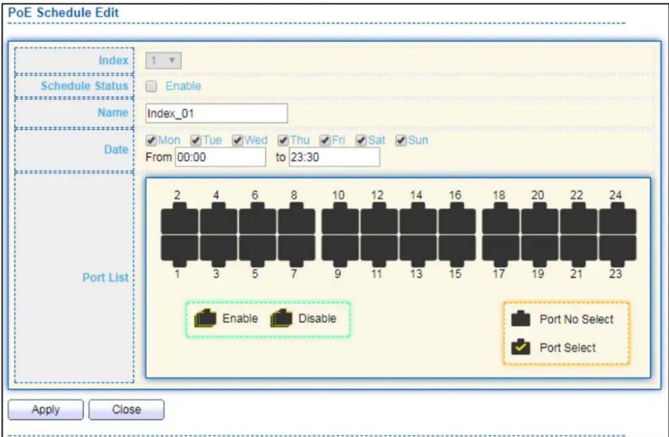
text_image
PoE Schedule Edit Index Schedule Status Enable Name Index_01 Date Mon Tue Wed Thu Fri Sat Sun From 00:00 to 23:30 Port List 2 4 6 8 10 12 14 16 18 20 22 24 1 3 5 7 9 11 13 15 17 19 21 23 Enable Disable Port No Select Port Select Apply CloseFigure 39 - PoE > Priority Seng > Edit PoE Schedule Edit
| Item | Descripon |
| Index | The serial number of schedule list. |
| Schedule Status | Schedule Status● Checked: Schedule status is enabled.● Unchecked: Schedule status is disabled. |
| Name | Enter the PoE schedule name. |
| Date | Select a valid me for this schedule. |
| Port List | Select the port provide power. |
IV-4-2 Priority Seng
Use this secon to set the power supply priority of PoE ports. Individual ports can be assigned critical, high, or low power supply priority.
To display the Priority Seng web page, click PoE > Priority Setng.

bar
| Category | Critical Priority | High Priority | Low Priority | |---|---|---|---| | 1 | 2 | 0 | 0 | | 3 | 4 | 0 | 0 | | 5 | 6 | 0 | 0 | | 7 | 8 | 0 | 0 | | 9 | 10 | 0 | 0 | | 11 | 12 | 0 | 0 | | 13 | 14 | 0 | 0 | | 15 | 16 | 0 | 0 | | 17 | 18 | 0 | 0 | | 19 | 20 | 0 | 0 | | 21 | 22 | 0 | 0 | | 23 | 24 | 0 | 0 | ApplyFigure 40 - PoE > Priority Seng
Click the port to change its priority status according to the boom right hand chart.
IV-4-3 Power Limit
To display the Power Limit web page, click PoE > Power Limit.
| Power Limit Setting Table | |||
| Entry | Port | Power Limit | |
| 1 | GE1 | 30000mW | |
| 2 | GE2 | 30000mW | |
| 3 | GE3 | 30000mW | |
| 4 | GE4 | 30000mW | |
| 5 | GE5 | 30000mW | |
| 6 | GE6 | 30000mW | |
| 7 | GE7 | 30000mW | |
| 8 | GE8 | 30000mW | |
| 9 | GE9 | 30000mW | |
| 10 | GE10 | 30000mW | |
| 11 | GE11 | 30000mW | |
| 12 | GE12 | 30000mW | |
| 13 | GE13 | 30000mW | |
| 14 | GE14 | 30000mW | |
| 15 | GE15 | 30000mW | |
| 16 | GE16 | 30000mW | |
| 17 | GE17 | 30000mW | |
| 18 | GE18 | 30000mW | |
| 19 | GE19 | 30000mW | |
| 20 | GE20 | 30000mW | |
| 21 | GE21 | 30000mW | |
| 22 | GE22 | 30000mW | |
| 23 | GE23 | 30000mW | |
| 24 | GE24 | 30000mW | |
Figure 41 - PoE > Power Limit
| Item | Descripon |
| Port | Port name. |
| Power Limit | The max supply power for this port. |
Click "Edit" to view Power Limit Seng menu.
text_image
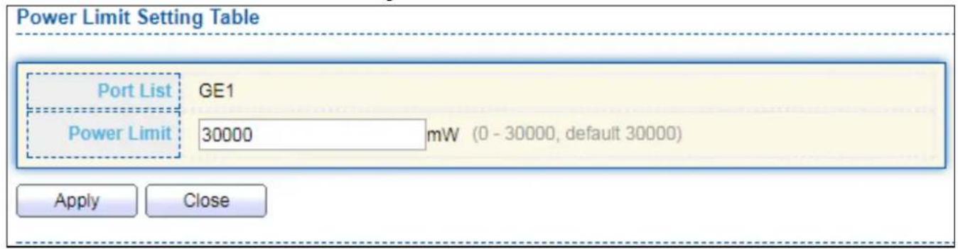
Power Limit Setting Table Port List GE1 Power Limit 30000 mW (0 - 30000, default 30000) Apply CloseFigure 42 - PoE > Power Seng > Power Limit Seng Table
| Item | Descripon |
| Port List | Selected port list. |
| Power Limit | Enter max supply power value for the selected port list. |
IV-4-4 PoE Status
To display the PoE Status web page, click PoE > Power Status.
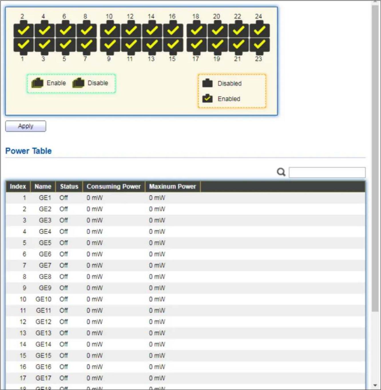
other
| Index | Name | Status | Consuming Power (mW) | Maximum Power (mW) | | :--- | :--- | :--- | :--- | :--- | | 1 | GE1 | Off | 0 mW | 0 mW | | 2 | GE2 | Off | 0 mW | 0 mW | | 3 | GE3 | Off | 0 mW | 0 mW | | 4 | GE4 | Off | 0 mW | 0 mW | | 5 | GE5 | Off | 0 mW | 0 mW | | 6 | GE6 | Off | 0 mW | 0 mW | | 7 | GE7 | Off | 0 mW | 0 mW | | 8 | GE8 | Off | 0 mW | 0 mW | | 9 | GE9 | Off | 0 mW | 0 mW | | 10 | GE10 | Off | 0 mW | 0 mW | | 11 | GE11 | Off | 0 mW | 0 mW | | 12 | GE12 | Off | 0 mW | 0 mW | | 13 | GE13 | Off | 0 mW | 0 mW | | 14 | GE14 | Off | 0 mW | 0 mW | | 15 | GE15 | Off | 0 mW | 0 mW | | 16 | GE16 | Off | 0 mW | 0 mW | | 17 | GE17 | Off | 0 mW | 0 mW | | 18 | Enable | Disable | Disabled / Enabled | Disabled / Enabled | | 19-23: Enable / Disable: Applied; Power Table: Power Table.Figure 43 - PoE > Power Stauts
Per Port PoE Status
Checked: Port PoE status is enabled.
Unchecked: Port PoE status is disabled.
IV-4-5 PD (Powered Device) Alive Check
To display the PD Alive Check web page, click PoE > PD Alive Check.
| Entry | Port | Mode | ping PD IP Address | Interval Time | Retry Count | Action | Reboot Time | Connect Status |
| 1 | GE1 | Enable | 192.158.2.2 | 30 | 2 | Alarm | 90 | Off |
| 2 | GE2 | Disable | 0.0.0.0 | 30 | 2 | None | 90 | Off |
| 3 | GE3 | Disable | 0.0.0.0 | 30 | 2 | None | 90 | Off |
| 4 | GE4 | Disable | 0.0.0.0 | 30 | 2 | None | 90 | Off |
| 5 | GE5 | Disable | 0.0.0.0 | 30 | 2 | None | 90 | Off |
| 6 | GE6 | Disable | 0.0.0.0 | 30 | 2 | None | 90 | Off |
| 7 | GE7 | Disable | 0.0.0.0 | 30 | 2 | None | 90 | Off |
| 8 | GE8 | Disable | 0.0.0.0 | 30 | 2 | None | 90 | Off |
| 9 | GE9 | Disable | 0.0.0.0 | 30 | 2 | None | 90 | Off |
| 10 | GE10 | Disable | 0.0.0.0 | 30 | 2 | None | 90 | Off |
| 11 | GE11 | Disable | 0.0.0.0 | 30 | 2 | None | 90 | Off |
| 12 | GE12 | Disable | 0.0.0.0 | 30 | 2 | None | 90 | Off |
| 13 | GE13 | Disable | 0.0.0.0 | 30 | 2 | None | 90 | Off |
| 14 | GE14 | Disable | 0.0.0.0 | 30 | 2 | None | 90 | Off |
| 15 | GE15 | Disable | 0.0.0.0 | 30 | 2 | None | 90 | Off |
| 16 | GE16 | Disable | 0.0.0.0 | 30 | 2 | None | 90 | Off |
| 17 | GE17 | Disable | 0.0.0.0 | 30 | 2 | None | 90 | Off |
| 18 | GE18 | Disable | 0.0.0.0 | 30 | 2 | None | 90 | Off |
| 19 | GE19 | Disable | 0.0.0.0 | 30 | 2 | None | 90 | Off |
| 20 | GE20 | Disable | 0.0.0.0 | 30 | 2 | None | 90 | Off |
| 21 | GE21 | Disable | 0.0.0.0 | 30 | 2 | None 90 Off | ||
Figure 44 - PoE > PD Alive Check
Click "Edit" buon to view Edit PD Alive Check menu.
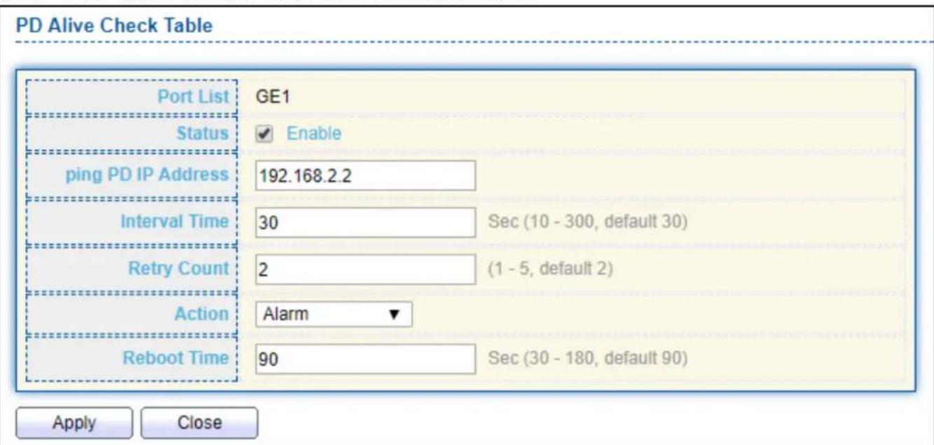
text_image
PD Alive Check Table Port List GE1 Status ✓ Enable ping PD IP Address 192.168.2.2 Interval Time 30 Sec (10 - 300, default 30) Retry Count 2 (1 - 5, default 2) Action Alarm ▼ Reboot Time 90 Sec (30 - 180, default 90) Apply CloseFigure 45 - PoE > PD Alive Check > Edit PD Alive Check
| Item | Descripon |
| Port List | Port name. |
| Status | Check to enable PD Alive Check. |
| Ping PD IP Address | IP address of connected device. |
| Interval Time | The me interval of how long the system issues a ping request to the connected PD to check if the device is dead or alive.Time range is 10-300 seconds. |
| Retry Count | This column allows users to set how many mes the system retries issuing a ping request to the PD. Aer the retries and fails, the system will carry out the “Acon” below.For example, if “Retry Count” is set to 2, and the system nds the device dead, the system will retry 2 ping requests. If the 2 retries fail, the system will carry out the “Acon”. |
| Acon | The acon taken if the retry count reaches the set number:● None: No acon.● Alarm: The switch issues an alarm message via Syslog.● PD Reboot: The switch reboots the PoE port.● Reboot & Alarm: The switch reboots the PoE port and issue an alarm message via Syslog. |
| Reboot Time | Set a reboot me between 30-180 seconds.Due to many kinds of PDs having dierent reboot me, please be aware of how long they will nish boong up.The system will check the PD again aer the reboot me. If you are unsure of the boot up me, it is recommended to set it longer. |
IV-5 VLAN
A virtual local area network, virtual LAN or VLAN, is a group of hosts with a common set of requirements that communicate as if they were aached to the same broadcast domain, regardless of their physical locaon. A VLAN has the same aributes as a physical local area network (LAN), but it allows for end staons to be grouped together even if they are not located on the same network switch. VLAN membership can be congured through sware instead of physically relocang devices or conncons.
IV-5-1 VLAN
Use the VLAN pages to congregate sengs of VLAN.
IV-5-1-1 Create VLAN
This page allows user to add or delete VLAN ID entries and browser all VLAN entries that add stacally or dynamic learned by GVRP. Each VLAN entry has a unique name, user can edit VLAN name in edit page.
To display Create VLAN page, click VLAN > VLAN > Create VLAN.

text_image
VLAN Available VLAN Created VLAN VLAN 2 VLAN 3 VLAN 4 VLAN 5 VLAN 6 VLAN 7 VLAN 8 VLAN 9 VLAN 1 Apply VLAN Table Showing All entries Showing 1 to 1 of 1 entries VLAN Name Type 1 default Default Edit Delete First Previous 1 Next LastFigure 46 - VLAN > VLAN > Create VLAN
| Item | Descripon |
| Available VLAN | VLAN has not created yet.Select available VLANs from le box then move to right box to add. |
| Created VLAN | VLAN had been created.Select created VLANs from right box then move to le box to delete |
| VLAN | The VLAN ID. |
| Name | The VLAN Name. |
| Type | The VLAN Type.• Stac: Port base VLAN.• Dynamic: 802.1q VLAN. |
Click "Edit" buon to view Edit VLAN Name menu.
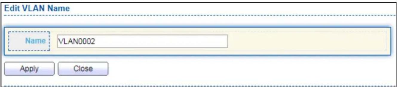
text_image
Edit VLAN Name Name VLAN0002 Apply CloseFigure 47 - VLAN > VLAN > Create VLAN > Edit VLAN Name
| Item | Descripon |
| Name | Input VLAN name. |
IV-5-1-2 VLAN Conguraon
This page allows user to congregate the membership for each port of selected VLAN.
To display VLAN Configuraon page, click VLAN > VLAN > VLAN Conguraon.
| Entry | Port | Mode | Membership | PVID | ||||
| 1 | GE1 | Trunk | ○ Excluded | ○ Forbidden | ○ Tagged | ● Untagged | ✓ | |
| 2 | GE2 | Trunk | ○ Excluded | ○ Forbidden | ○ Tagged | ● Untagged | ✓ | |
| 3 | GE3 | Trunk | ○ Excluded | ○ Forbidden | ○ Tagged | ● Untagged | ✓ | |
| 4 | GE4 | Trunk | ○ Excluded | ○ Forbidden | ○ Tagged | ● Untagged | ✓ | |
| 5 | GE5 | Trunk | ○ Excluded | ○ Forbidden | ○ Tagged | ● Untagged | ✓ | |
| 6 | GE6 | Trunk | ○ Excluded | ○ Forbidden | ○ Tagged | ● Untagged | ✓ | |
| 7 | GE7 | Trunk | ○ Excluded | ○ Forbidden | ○ Tagged | ● Untagged | ✓ | |
| 8 | GE8 | Trunk | ○ Excluded | ○ Forbidden | ○ Tagged | ● Untagged | ✓ | |
| 9 | GE9 | Trunk | ○ Excluded | ○ Forbidden | ○ Tagged | ● Untagged | ✓ | |
| 10 | GE10 | Trunk | ○ Excluded | ○ Forbidden | ○ Tagged | ● Untagged | ✓ | |
| 11 | GE11 | Trunk | ○ Excluded | ○ Forbidden | ○ Tagged | ● Untagged | ✓ | |
| 12 | GE12 | Trunk | ○ Excluded | ○ Forbidden | ○ Tagged | ● Untagged | ✓ | |
| 13 | GE13 | Trunk | ○ Excluded | ○ Forbidden | ○ Tagged | ● Untagged | ✓ | |
| 14 | GE14 | Trunk | ○ Excluded | ○ Forbidden | ○ Tagged | ● Untagged | ✓ | |
| 15 | GE15 | Trunk | ○ Excluded | ○ Forbidden | ○ Tagged | ● Untagged | ✓ | |
| 16 | GE16 | Trunk | ○ Excluded | ○ Forbidden | ○ Tagged | ● Untagged | ✓ | |
| 17 | GE17 | Trunk | ○ Excluded | ○ Forbidden | ○ Tagged | ● Untagged | ✓ | |
| 18 | GE18 | Trunk | ○ Excluded | ○ Forbidden | ○ Tagged | ● Untagged | ✓ | |
| 19 | GE19 | Trunk | ○ Excluded | ○ Forbidden | ○ Tagged | ● Untagged | ✓ | |
| 20 | GE20 | Trunk | ○ Excluded | ○ Forbidden | ○ Tagged | ● Untagged | ✓ | |
| 21 | GE21 | Trunk | ○ Excluded | ○ Forbidden | ○ Tagged | ● Untagged | ✓ | |
| 22 | GE22 | Trunk | ○ Excluded | ○ Forbidden | ○ Tagged | ● Untagged | ✓ | |
| 23 | GE23 | Trunk | ○ Excluded | ○ Forbidden | ○ Tagged | ● Untagged | ✓ | |
| 24 | GE24 | Trunk | ○ Excluded | ○ Forbidden | ○ Tagged | ● Untagged | ✓ | |
| 25 | GE25 | Trunk | ○ Excluded | ○ Forbidden | ○ Tagged | ● Untagged | ✓ | |
| 26 | GE26 | Trunk | ○ Excluded | ○ Forbidden | ○ Tagged | ● Untagged | ✓ | |
| 27 GE27 Trunk | ||||||||
Figure 48 - VLAN > VLAN > VLAN Conguraon
| Item | Descripon |
| VLAN | Select specied VLAN ID to congregate VLAN conguraon. |
| Port | Display the interface of port entry. |
| Mode | Display the interface VLAN mode of port. |
| Membership | Select the membership for this port of the specied VLAN ID.● Forbidden: Specify the port is forbidden in the VLAN.● Excluded: Specify the port is excluded in the VLAN. ● Tagged: Specify the port is tagged member in the VLAN. ● Untagged: Specify the port is untagged member in the VLAN. |
| PVID | Display if it is PVID of interface. |
IV-5-1-3 Membership
This page allows user to view membership informaon for each port and edit membership for specied interface.
To display Membership page, click VLAN > VLAN > Membership.

Figure 49 - VLAN > VLAN > Membership
| Item | Descripon |
| Port | Display the interface of port entry. |
| Mode | Display the interface VLAN mode of port. |
| Administrave VLAN | Display the administrave VLAN list of this port. |
| Operaonal VLAN | Display the operaonal VLAN list of this port. Operaonal VLAN means the VLAN status that really runs in device. It may dierent to administrave VLAN. |
Click "Edit" buon to view the Edit Port Seng menu

text_image
Edit Port Setting Port Mode Membership GE1 Trunk 2 1UP Forbidden Excluded Tagged Untagged PVID Apply CloseFigure 50 - VLAN > VLAN > Membership > Edit Port Seng
| Item | Descripon |
| Port | Display the interface. |
| Mode | Display the VLAN mode of interface. |
| Membership | Select VLANs of le box and select one of following membership then move to right box to add membership. Select VLANs of right box then move to le box to remove membership. Tagging membership may not choose in dier VLAN port mode. Select the me source.Forbidden: Set VLAN as forbidden VLAN.Excluded: This opon is always disabled.Tagged: Set VLAN as tagged VLAN.Untagged: Set VLAN as untagged VLAN.PVID: Check this checkbox to select the VLAN ID to be the port-basedVLAN ID for this port. PVID may auto select or can’t select in dier sengs. |
IV-5-1-4 Port Seng
This page allows user to congregate ports VLAN sengs such as VLAN port mode, PVID etc...The aributes depend on dierent VLAN port mode.
To display Port Seng page, click VLAN > VLAN > Port Seng.
| Port Setting Table | ||||||||||||
| Entry | Port | Mode | PVID | Accept Frame Type | Ingress Filtering | Uplink | TPID | |||||
| 1 | GE1 | Trunk | 1 | All | Enabled | Disabled | 0x8100 | |||||
| 2 | GE2 | Trunk | 1 | All | Enabled | Disabled | 0x8100 | |||||
| 3 | GE3 | Trunk | 1 | All | Enabled | Disabled | 0x8100 | |||||
| 4 | GE4 | Trunk | 1 | All | Enabled | Disabled | 0x8100 | |||||
| 5 | GE5 | Trunk | 1 | All | Enabled | Disabled | 0x8100 | |||||
| 6 | GE6 | Trunk | 1 | All | Enabled | Disabled | 0x8100 | |||||
| 7 | GE7 | Trunk | 1 | All | Enabled | Disabled | 0x8100 | |||||
| 8 | GE8 | Trunk | 1 | All | Enabled | Disabled | 0x8100 | |||||
| 9 | GE9 | Trunk | 1 | All | Enabled | Disabled | 0x8100 | |||||
| 10 | GE10 | Trunk | 1 | All | Enabled | Disabled | 0x8100 | |||||
| 11 | GE11 | Trunk | 1 | All | Enabled | Disabled | 0x8100 | |||||
| 12 | GE12 | Trunk | 1 | All | Enabled | Disabled | 0x8100 | |||||
| 13 | GE13 | Trunk | 1 | All | Enabled | Disabled | 0x8100 | |||||
| 14 | GE14 | Trunk | 1 | All | Enabled | Disabled | 0x8100 | |||||
| 15 | GE15 | Trunk | 1 | All | Enabled | Disabled | 0x8100 | |||||
| 16 | GE16 | Trunk | 1 | All | Enabled | Disabled | 0x8100 | |||||
| 17 | GE17 | Trunk | 1 | All | Enabled | Disabled | 0x8100 | |||||
| 18 | GE18 | Trunk | 1 | All | Enabled | Disabled | 0x8100 | |||||
| 19 | GE19 | Trunk | 1 | All | Enabled | Disabled | 0x8100 | |||||
| 20 | GE20 | Trunk | 1 | All | Enabled | Disabled | 0x8100 | |||||
| 21 | GE21 | Trunk | 1 | All | Enabled | Disabled | 0x8100 | |||||
| 22 | GE22 | Trunk | 1 | All | Enabled | Disabled | 0x8100 | |||||
| 23 | GE23 | Trunk | 1 | AllI. . . . . . . . . . . . . . . . . . . . . . . . . . . . . . . . . . . . . . . . . . . . . . . . . . . . . . . . . . . . . . . . . . . . . . . . . . . . . . 24 GE24 Trunk 1 All Enabled Disabled 0x8100 25 GE25 Trunk 1 All Enabled Disabled 0x8100 26 GE26 Trunk 1 All Enabled Disabled 0x8100 27 GE27 Trunk 1 All Enabled Disabled 0x8100 28 GE28 Trunk 1 All Enabled Disabled 0x8100 29 LAG1 Trunk 1 All Enabled Disabled 0x8100 30 LAG2 Trunk 1 All Enabled Disabled 0x8100 | ||||||||
Figure 51 - VLAN > VLAN > Port Seng
| Item | Descripon |
| Port | Display the interface. |
| Mode | Display the VLAN mode of interface. |
| PVID | Display the Port-based VLAN ID of port. |
| Accept Frame Type | Display accept frame type of port. |
| Ingress Filtering | Display ingress lter status of port. |
| Uplink | Display uplink status. |
| TPID | Display TPID used of interface. |
Click "Edit" buon to Edit Port Seng menu.
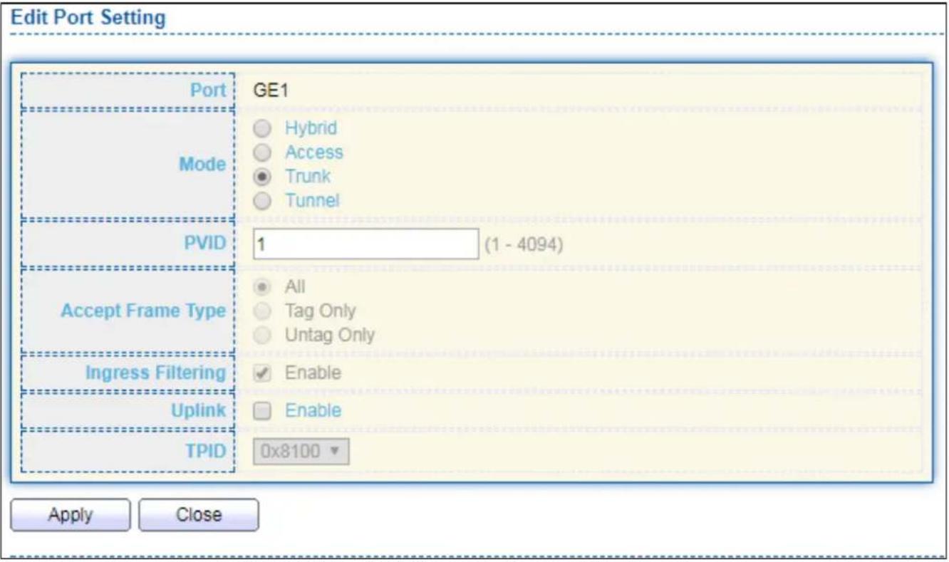
text_image
Edit Port Setting Port GE1 Mode Hybrid Access Trunk Tunnel PVID 1 (1 - 4094) Accept Frame Type All Tag Only Untag Only Ingress Filtering Enable Uplink Enable TPID 0x8100 Apply CloseFigure 52 - VLAN > VLAN > Port Seng > Edit Port Seng
| Item | Descripon |
| Port | Display selected port to be edited. |
| Mode | Select the VLAN mode of the interface.● Forbidden: Set VLAN as forbidden VLAN.● Hybrid: Support all funcons as denied in IEEE 802.1Q specicaon.● Access: Accepts only untagged frames and join an untagged VLAN.● Trunk: An untagged member of one VLAN at most, and is a tagged member of zero or more VLANs. |
| PVID | Specify the port-based VLAN ID (1-4094). It’s only available with Hybrid and Trunk mode. |
| Accepted Type | Specify the acceptable-frame-type of the specied interfaces. It’s only available with Hybrid mode. |
| Ingress | Set checkbox to enable/disable ingress ltering. It’s only available with |
| Filtering | Hybrid mode. |
| Uplink | Set checkbox to enable/disable uplink mode. It’s only available with trunk mode. |
| TPID | Select TPID used of interface. It’s only available with trunk mode. |
IV-5-2 Voice VLAN
Use the Voice VLAN pages to congregate sengs of Voice VLAN.
IV-5-2-1 Property
This page allows user to congregate global and per interface sengs of voice VLAN.
To display Property Web page, click VLAN> Voice VLAN> Property.

text_image
State VLAN CoS / 802.1p Remarking Aging Time Enable None Enable 6 1440 Sec (30 - 65536, default 1440) Apply Port Setting Table Q Entry Port State Mode QoS Policy 1 GE1 Disabled Auto Voice Packet 2 GE2 Disabled Auto Voice Packet 3 GE3 Disabled Auto Voice Packet 4 GE4 Disabled Auto Voice Packet 5 GE5 Disabled Auto Voice Packet 6 GE6 Disabled Auto Voice Packet 7 GE7 Disabled Auto Voice Packet 8 GE8 Disabled Auto Voice Packet 9 GE9 Disabled Auto Voice Packet 10 GE10 Disabled Auto Voice Packet 11 GE11 Disabled Auto Voice Packet 12 GE12 Disabled Auto Voice Packet 13 GE13 Disabled Auto Voice Packet 14 GE14 Disabled Auto Voice Packet 15 GE15 Disabled Auto Voice Packet 16 GE16 Disabled Auto Voice Packet 17 GE17 Disabled Auto Voice Packet 18 GE18 Disabled Auto Voice Packet 19 GE19 Disabled Auto Voice Packet 20 GE20 Disabled Auto Voice PacketFigure 53 - VLAN > Voice VLAN > Property
| Item | Descripon |
| State | Set checkbox to enable or disable voice VLAN funcon. |
| VLAN | Select Voice VLAN ID. Voice VLAN ID cannot be default VLAN. |
| Cos/802.1p | Select a value of VPT. Qualified packets will use this VPT value as inner priority. |
| Remarking | Set checkbox to enable or disable 1p remarking. If enabled, qualified packets will be remark by this value. |
| Aging Time | Input value of aging me. Default is 1440 minutes. A voice VLAN entry will be age out aer this me if without any packet pass through. |
| Port Seng Table | |
| Port | Display port entry. |
| State | Display enable/disabled status of interface. |
| Mode | Display voice VLAN mode. |
| QoS Policy | Display voice VLAN remark will eect which kind of packet. |
Click "Edit" buon to view Edit Port Seng menu.

text_image
Edit Port Setting Port GE1 State Enable Mode Auto Manual QoS Policy Voice Packet All Apply CloseFigure 54 - VLAN > Voice VLAN > Property > Edit Port Seng
| Item | Descripon |
| Port | Display selected port to be edited. |
| State | Set checkbox to enable/disabled voice VLAN funcon of interface. |
| Mode | Select port voice VLAN mode● Auto: Voice VLAN auto detect packets that match OUI table and add received port into voice VLAN ID tagged member.● Manual: User need add interface to VLAN ID tagged member manually. |
| QoS Policy | Select port QoS Policy mode● Voice Packet: QoS aributes are applied to packets with OUIs in the source MAC address.● All: QoS aributes are applied to packets that are classied to Voice VLAN. |
IV-5-2-2 Voice OUI
This page allows user to add, edit or delete OUI MAC addresses. Default has 8 pre-dened OUI MAC.
To display the Voice OUI Web page, click VLAN > Voice VLAN > Voice OUI.
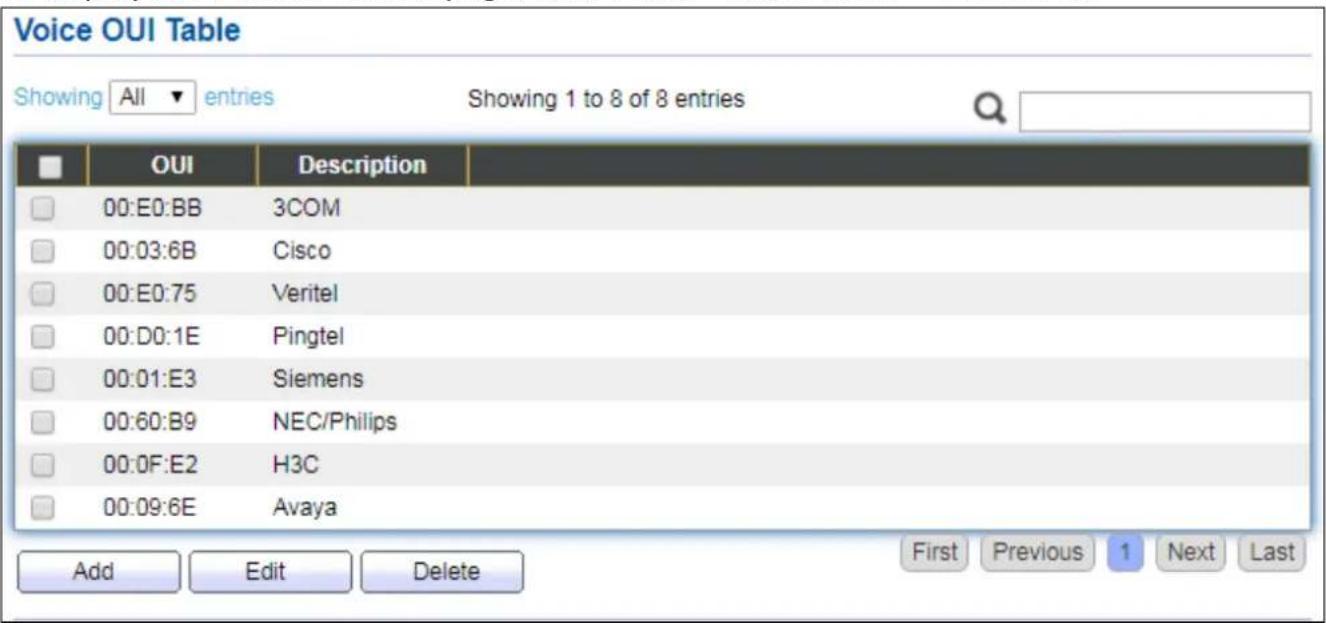
text_image
Voice OUI Table Showing All entries Showing 1 to 8 of 8 entries OUI Description 00:E0:BB 3COM 00:03:6B Cisco 00:E0:75 Veritel 00:D0:1E Pingtel 00:01:E3 Siemens 00:60:B9 NEC/Philips 00:0F:E2 H3C 00:09:6E Avaya Add Edit Delete First Previous 1 Next LastFigure 55 - VLAN > Voice VLAN > Voice OUI
| Item | Descripon |
| OUI | Display OUI MAC address. |
| Descripon | Display descripon of OUI entry. |
Click "Add" or "Edit" buon to Add/Edit Voice OUI menu.

text_image
Add Voice OUI OUI : : : Description Apply Close Edit Voice OUI OUI 00:03:6B Description Cisco Apply CloseFigure 56 - VLAN > Voice VLAN > Voice OUI > Add/Edit Voice OUI
| Item | Descripon |
| OUI | Input OUI MAC address. Can’t be edited in edit dialog. |
| Descripon | Input descripon of the specied MAC address to the voice VLAN OUI table. |
IV-5-3 MAC VLAN
Use the MAC VLAN pages to congregate sengs of MAC VLAN.
IV-5-3-1 MAC Group
This page allows user to add or edit groups sengs of MAC VLAN.
To display the MAC page, click VLAN > MAC VLAN > MAC Group.
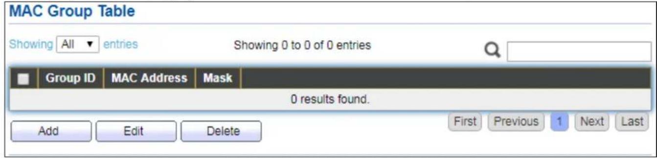
text_image
MAC Group Table Showing All entries Showing 0 to 0 of 0 entries Group ID MAC Address Mask 0 results found. Add Edit Delete First Previous 1 Next LastFigure 57 - VLAN > MAC VLAN > MAC Group
| Item | Descripon |
| Group ID | Display group ID of entry. |
| MAC Address | Display mac address of entry. |
| Mask | Display mask of mac address for classied packet. |
Click "Add" buon or "Edit" buon to view Add/Edit MAC menu.
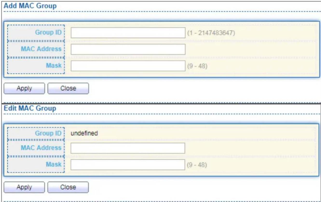
text_image
Add MAC Group Group ID (1 - 2147483647) MAC Address Mask (9 - 48) Apply Close Edit MAC Group Group ID undefined MAC Address Mask (9 - 48) Apply CloseFigure 58 - VLAN > MAC VLAN > MAC Group > Add/Edit MAC
| Item | Descripon |
| Group ID | Input group ID that is a unique ID of mac group entry. The range from 1 to 2147483647. Only available on Add Dialog. |
| MAC Address | Input mac address for classifying packets. |
| Mask | Input mask of mac address. |
IV-5-3-2 Group Binding
This page allows user to bind MAC VLAN group to each port with VLAN ID.
To display Group Binding page, click VLAN> MAC VLAN > Group Binding.
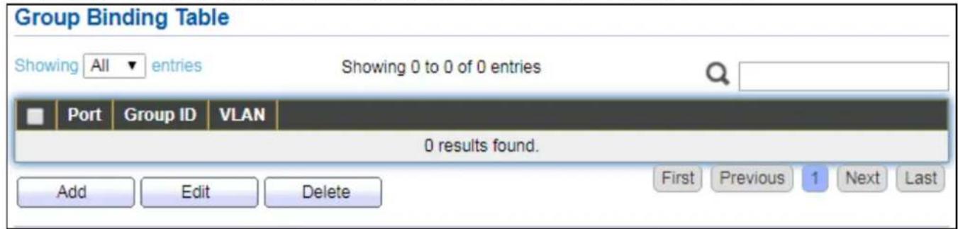
text_image
Group Binding Table Showing All entries Showing 0 to 0 of 0 entries Port Group ID VLAN 0 results found. Add Edit Delete First Previous 1 Next LastFigure 59 - VLAN > MAC VLAN > Group Binding
| Item | Descripon |
| Port | Display port ID that binding with MAC group entry. |
| Group ID | Display group ID that port binding with. |
| VLAN | Display VLAN ID that assign to packets which match MAC group. |
Click "Add" or "Edit" buon to view the Add/Edit Group Binding menu.
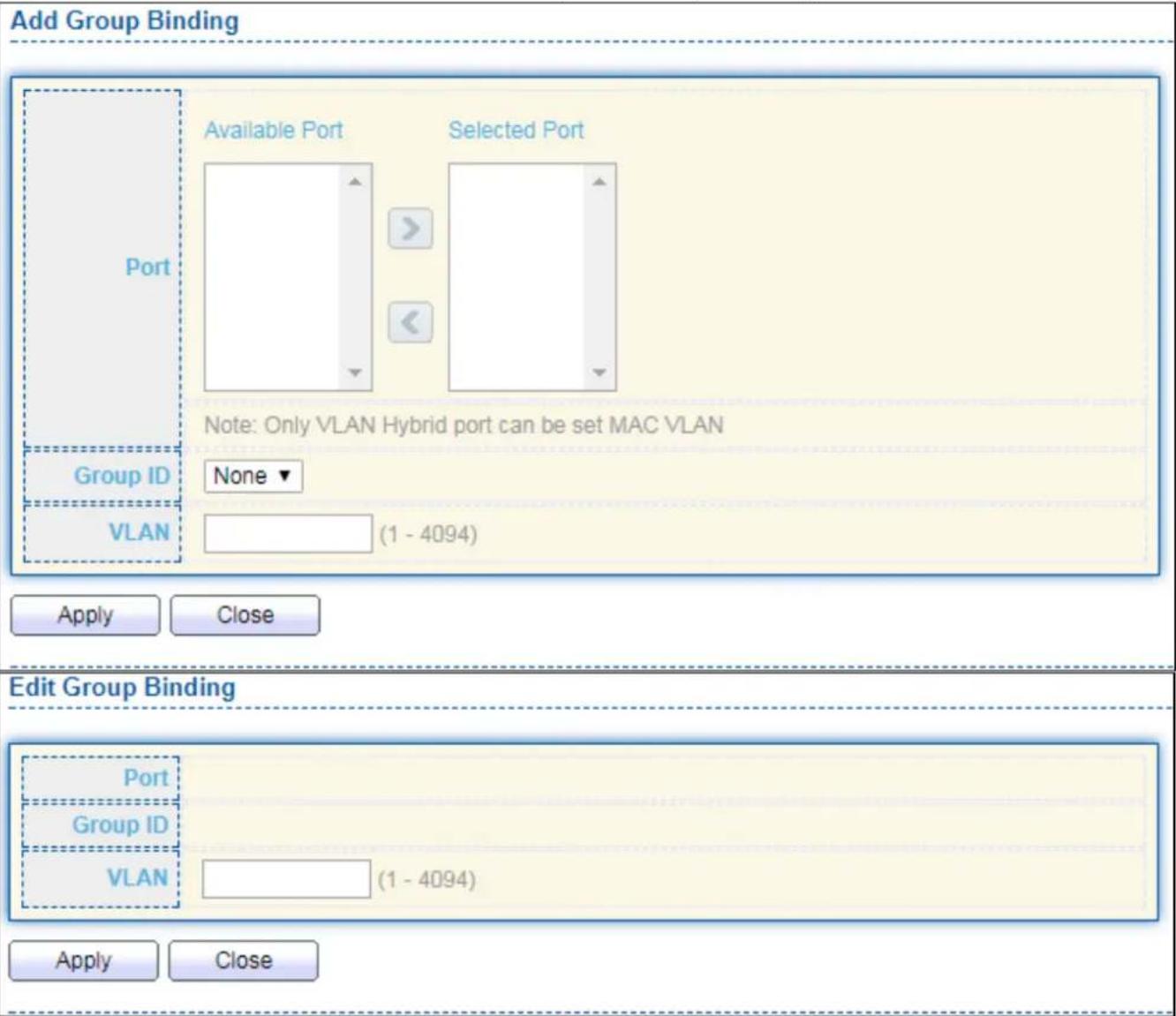
text_image
Add Group Binding Available Port Selected Port Port Note: Only VLAN Hybrid port can be set MAC VLAN Group ID None VLAN (1 - 4094) Apply Close Edit Group Binding Port Group ID VLAN (1 - 4094) Apply CloseFigure 60 - VLAN > MAC VLAN > Add/Edit Group Binding
| Item | Descripon |
| Port | Select ports in le box then move to right to binding with MAC group. Or select ports in right box then move to le to unbind with MAC group. Only interface has hybrid VLAN mode can be selected and bound with protocol group. Only available on Add dialog. |
| Group ID | Select a Group ID to associate with port. Only available on Add dialog. |
| VLAN | Input VLAN ID that will assign to packets which match MAC group. |
IV-6 MAC Address Table
Use the MAC Address Table pages to show dynamic MAC table and congure sengs for stac MAC entries.
IV-6-1 Dynamic Address
To display the Dynamic Address web page, click MAC Address Table > Dynamic Address.
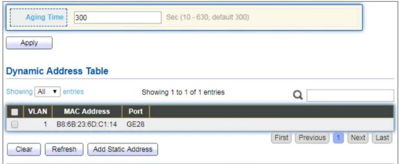
text_image
Aging Time 300 Sec (10 - 630, default 300) Apply Dynamic Address Table Showing All entries Showing 1 to 1 of 1 entries VLAN MAC Address Port 1 B8:6B:23:6D:C1:14 GE28 Clear Refresh Add Static Address First Previous 1 Next LastFigure 61 - MAC Address Table > Dynamic Address
| Item | Descripon |
| Aging Time | The me in seconds that an entry remains in the MAC address table. Its valid range is from 10 to 630 seconds, and the default value is 300 seconds. |
IV-6-2 Stac Address
To display the Stac Address web page, click MAC Address Table > Stac Address.

text_image
Static Address Table Showing All entries Showing 0 to 0 of 0 entries VLAN MAC Address Port 0 results found. Add Edit Delete First Previous 1 Next LastFigure 62 - MAC Address Table > Stac Address
| Item | Descripon |
| MAC Address | The MAC address to which packets will be stacally forwarded. |
| VLAN | Specify the VLAN to show or clear MAC entries. |
| Port | Interface or port number. |
IV-6-3 Filtering Address
To display the Filtering Address web page, click MAC Address Table > Filtering Address.
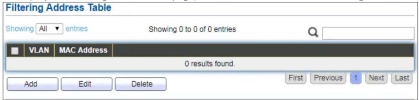
text_image
Filtering Address Table Showing All entries Showing 0 to 0 of 0 entries VLAN MAC Address 0 results found. Add Edit Delete First Previous 1 Next LastFigure 63 - MAC Address Table > Filtering Address
| Item | Descripon |
| MAC Address | Specify unicast MAC address in the packets to be dropped. |
| VLAN | Specify the VLAN to show or clear MAC entries. |
IV-7 Spanning Tree
The Spanning Tree Protocol (STP) is a network protocol that ensures a loop-free topology for any bridged Ethernet local area network.
IV-7-1 Property
To display the Property web page, click Spanning Tree > Property.
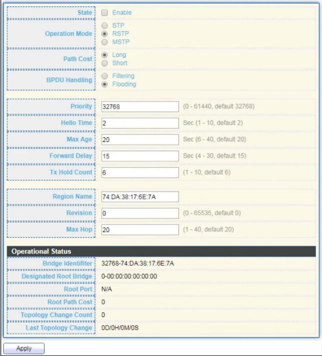
text_image
State Enable STP RSTP MSTP Operation Mode Path Cost Long Short BPDU Handling Filtering Flooding Priority 32768 (0 - 61440, default 32768) Hello Time 2 Sec (1 - 10, default 2) Max Age 20 Sec (6 - 40, default 20) Forward Delay 15 Sec (4 - 30, default 15) Tx Hold Count 6 (1 - 10, default 6) Region Name 74:DA:38:17:6E:7A Revision 0 (0 - 65535, default 0) Max Hop 20 (1 - 40, default 20) Operational Status Bridge Identifier 32768-74:DA:38:17:6E:7A Designated Root Bridge 0-00:00:00:00:00:00 Root Port N/A Root Path Cost 0 Topology Change Count 0 Last Topology Change 0D/OH/OM/OS ApplyFigure 64 - Spanning Tree > Property
| Item | Descripon |
| State | Enable/disable the STP on the switch. |
| Operaon Mode | Specify the STP operaon mode.STP: Enable the Spanning Tree (STP) operaon.RSTP: Enable the Rapid Spanning Tree (RSTP) operaon.MSTP: Enable the Mulple Spanning Tree (MSTP) operaon. |
| Path Cost | Specify the path cost method.Long: Species that the default port path costs are within the range: 1-200,000,000.Short: Species that the default port path costs are within the range: 1-65,535. |
| BPDU Handling | Specify the BPDU forward method when the STP is disabled.Filtering: Filter the BPDU when STP is disabled.Flooding: Flood the BPDU when STP is disabled. |
| Priority | Specify the bridge priority. The valid range is from 0 to 61440, and the value should be the mulple of 4096. It ensures the probability that the switch is selected as the root bridge, and the lower value has the higher priority for the switch to be selected as the root bridge of the topology. |
| Hello Time | Specify the STP hello me in second to broadcast its hello message to other bridges by Designated Ports. Its valid range is from 1 to 10 seconds. |
| Max Age | Specify the me interval in seconds for a switch to wait the conguraon messages, without aempng to redene its own conguraon. |
| Forward Delay | Specify the STP forward delay me, which is the amount of me that a port remains in the Listening and Learning states before it enters the Forwarding state. Its valid range is from 4 to 10 seconds. |
| TX Hold Count | Specify the tx-hold-count used to limit the maximum numbers of packets transmission per second. The valid range is from 1 to 10. |
| Region Name | The MSTP instance name. Its maximum length is 32 characters. The default value is the MAC address of the switch. |
| Revision | The MSTP revision number. Its valid rage is from 0 to 65535. |
| Max Hop | Specify the number of hops in an MSTP region before the BPDU is discarded. The valid range is 1 to 40. |
| Operational Status | |
| Bridge Idener | Bridge idener of the switch. |
| Designated Root Idener | Bridge idener of the designated root bridge. |
| Root Port | Operational root port of the switch. |
| Root Path Cost | Operational root path cost. |
| Topology Change Count | Numbers of the topology changes. |
| Last Topology Change | The last me for the topology change. |
IV-7-2 Port Seng
To congure and display the STP port sengs, click STP > Port Seng.
| Port Setting Table | ||||||||||||||
| Entry | Port | State | Path Cost | Priority | BPDU Filter | BPDU Guard | Operational Edge | Operational Point-to-Point | Port Role | Port State | Designated Bridge | Designated Port ID | Designated Cost | |
| 1 | GE1 | Enabled | 20000 | 128 | Disabled | Disabled | Disabled | Disabled | Disabled | Disabled | 0-00:00:00:00:00:00 | 128-1 | 20000 | |
| 2 | GE2 | Enabled | 20000 | 128 | Disabled | Disabled | Disabled | Disabled | Disabled | Disabled | 0-00:00:00:00:00:00 | 128-2 | 20000 | |
| 3 | GE3 | Enabled | 20000 | 128 | Disabled | Disabled | Disabled | Disabled | Disabled | Disabled | 0-00:00:00:00:00:00 | 128-3 | 20000 | |
| 4 | GE4 | Enabled | 20000 | 128 | Disabled | Disabled | Disabled | Disabled | Disabled | Disabled | 0-00:00:00:00:00:00 | 128-4 | 20000 | |
| 5 | GE5 | Enabled | 20000 | 128 | Disabled | Disabled | Disabled | Disabled | Disabled | Disabled | 0-00:00:00:00:00:00 | 128-5 | 20000 | |
| 6 | GE6 | Enabled | 20000 | 128 | Disabled | Disabled | Disabled | Disabled | Disabled | Disabled | 0-00:00:00:00:00:00 | 128-6 | 20000 | |
| 7 | GE7 | Enabled | 20000 | 128 | Disabled | Disabled | Disabled | Disabled | Disabled | Disabled | 0-00:00:00:00:00:00 | 129-7 | 20000 | |
| 8 | GE8 | Enabled | 20000 | 128 | Disabled | Disabled | Disabled | Disabled | Disabled | Disabled | D- 5- 5- 5- 5- 5- 5- 5- 5- 5- 5- 5- 5- 5- 5- 5- 5- 5- 5- 5- 5- 5- 5- 5- 5- 5- 5- 5- 5- 5- 5- 5- 5- 5- 5 - 5 - 5 - 5 - 5 - 5 - 5 - 5 - 5 - 5 - 5 - 5 - 5 - 5 - 5 - 5 - 5 - 5 - 5 - 5 - 5 - 5 - 5 - 5 - 5 - 5 - 5 - 5 - 5 - 5 - 5 - 5 - 5 - 5 - | |||
| 9 | GE9 | Enabled | 20000 | 128 | Disabled | Disabled | Disabled | Disabled | Disabled | Disabled | D- 9- 9- 9- 9- 9- 9- 9- 9- 9- 9- 9- 9- 9- 9- 9- 9- 9- 9- 9- 9- 9- 9- 9- 9 - 9 - 9 - 9 - 9 - 9 - 9 - 9 - 9 - 9 - 9 - 9 - 9 - 9 - 9 - 9 - 9 - 9 - 9 - 9 - 9 - 9 - 9 - 9 - | |||
| 10 | GE10 | Enabled | 20000 | 128 | Disabled | Disabled | Disabled | Disabled | Disabled | Disabled | D- D- D- D- D- D- D- D- D- D- D- D- D- D- D- D- D- D- D- D- D- D- D- D- D- D- D- D- D- D- D- D- D- D- D- D- D- D- D- D- D- D- D- D- D- D- D- D- D- D- D- C. (1) (1) (1) (1) (1) (1) (1) (1) (1) (1) (1) (1) (1) (1) (1) (1) (1) (1) (1) (1) (1) (1) (1) (1) (1) (1) (1) (1) (1) (1) (1) (1) (1) (1) | |||
| 11 | GE11 | Enabled | 20000 | 128 | Disabled | Disabled | Disabled | Disabled | Disabled | Disabled | D- D- D- D- D- D- D- D- D- D- D- D- D- D- D- D- D- D- D- D- D- D- D- D- D- D- D- D- D- D. (1) (1) (1) (1) (1) (1) (1) (1) (1) (1) (1) (1) (1) (1) (1) (1) (1) (1) (1) (1) (1) (1) (1) (1) (1) (1) (1) (1) (1) (1) (1) (1) (1). (2) (2) (2) (2) (2) (2) (2) (2) (2) (2) (2) (2) (2) (2) (2) | |||
Figure 65 - Spanning Tree > Port Seng
| Item | Descripon |
| Port | Specify the interface ID or the list of interface IDs. |
| State | The operaonal state on the specied port. |
| Path Cost | STP path cost on the specied port. |
| Priority | STP priority on the specied port. |
| BPDU Filter | The states of BPDU Iter on the specied port. |
| BPDU Guard | The states of BPDU guard on the specied port. |
| Operaonal Edge | The operaonal edge port status on the specied port. |
| Operaonal Point-to-Point | The operaonal point-to-point status on the specied port. |
| Port Role | The current port role on the specied port. The possible values are: “Disabled”, “Master”, “Root”, “Designated”, “Alternave”, and “Backup”. |
| Port State | The current port state on the specied port. The possible values are: “Disabled”, “Discarding”, “Learning”, and “Forwarding”. |
| Designated Bridge | The bridge ID of the designated bridge. |
| Designated Port ID | The designated port ID on the switch. |
| Designated Cost | The path cost of the designated port on the switch. |
| ProtocolMigraon Check | Restart the Spanning Tree Protocol (STP) migraon process (re-negoate with its neighborhood) on the specic interface. |
Click "Edit" buon to view Edit Port Seng menu.
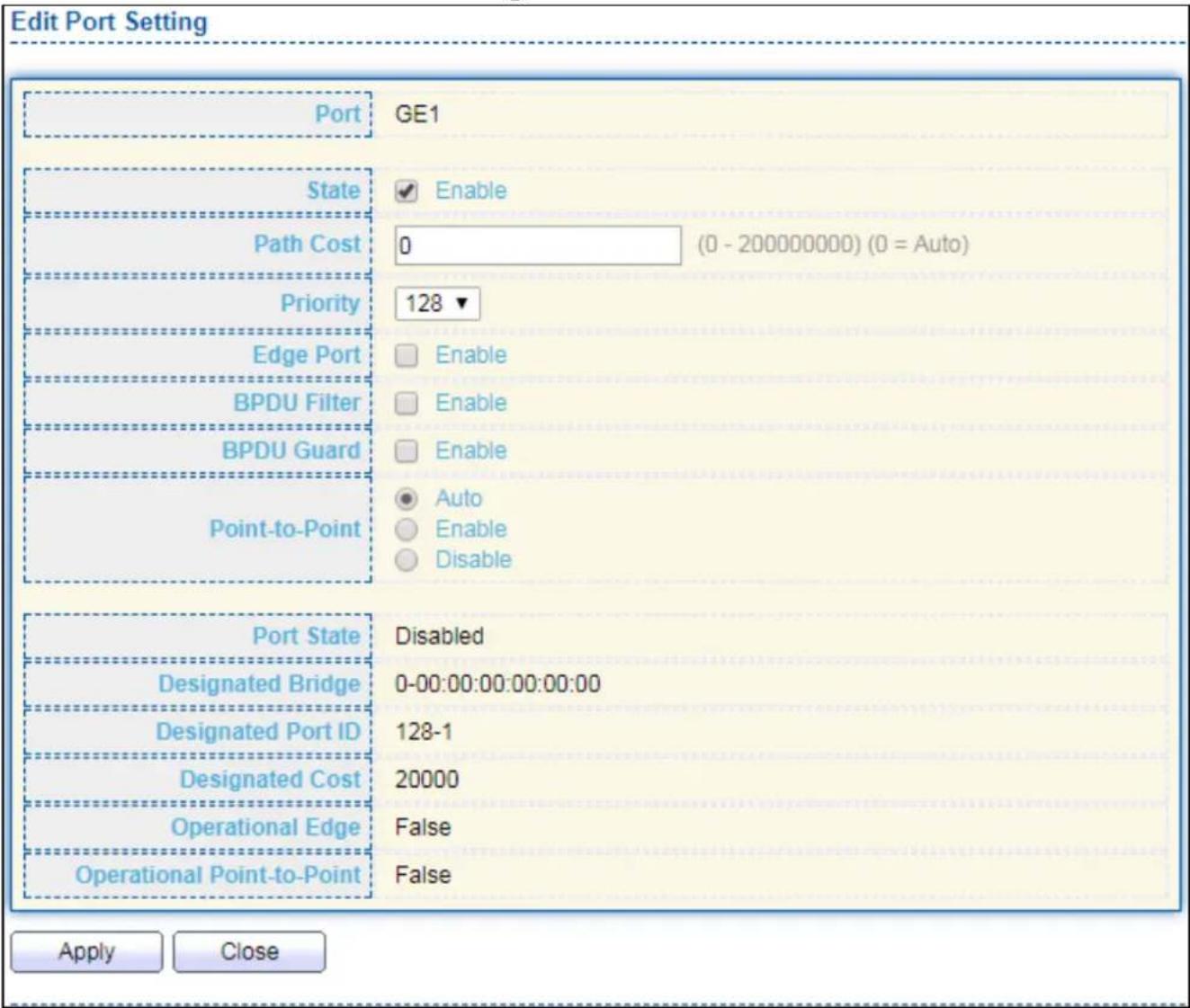
text_image
Edit Port Setting Port GE1 State Enable Path Cost 0 (0 - 200000000) (0 = Auto) Priority 128 ▼ Edge Port Enable BPDU Filter Enable BPDU Guard Enable Point-to-Point Auto Enable Disable Port State Disabled Designated Bridge 0-00:00:00:00:00:00 Designated Port ID 128-1 Designated Cost 20000 Operational Edge False Operational Point-to-Point False Apply CloseFigure 66 - Spanning Tree > Port Seng > Edit Port Seng
| Item | Descripon |
| Port | Selected port ID. |
| State | Enable/Disable the STP on the specied port. |
| Path Cost | Specify the STP path cost on the specied port. |
| Priority | Specify the STP path cost on the specied port. |
| Edge Port | Specify the edge mode.● Enable: Force to true state (as link to a host).● Disable: Force to false state (as link to a bridge).In the edge mode, the interface would be put into the Forwarding state immediately upon link up. If the edge mode is enabled for the interface and there are BPDUs received on the interface, the loop might be occurred in the short me before the STP state change. |
| BPDU Filter | The BPDU Filter conguraon avoids receiving / transming BPDU from the specied ports.● Enable: Enable BPDU Iter funcon.● Disable: Disable BPDU Iter funcon. |
| BPDU Guard | The BPDU Guard conguraon to drop the received BPDU directly.● Enable: Enable BPDU guard funcon.● Disable: Disable BPDU guard funcon. |
| Point-to-Point | Specify the Point-to-Point port conguraon:● Auto: The state is depended on the duplex seng of the port● Enable: Force to true state.● Disable: Force to false state |
IV-7-3 MST Instance
To congure MST instance seing, click STP > MST Instance.
| MSTI | Priority | Bridge Identifier | Designated Root Bridge | Root Port | Root Path Cost | Remaining Hop | VLAN |
| 0 | 32768 | 32768-74:DA:38:17:6E:7A | 0-00:00:00:00:00:00 | N/A | 0 | 0 | 1-4094 |
| 1 | 32768 | 32768-74:DA:38:17:6E:7A | 0-00:00:00:00:00:00 | N/A | 0 | 0 | |
| 2 | 32768 | 32768-74:DA:38:17:6E:7A | 0-00:00:00:00:00:00 | N/A | 0 | 0 | |
| 3 | 32768 | 32768-74:DA:38:17:6E:7A | 0-00:00:00:00:00:00 | N/A | 0 | 0 | |
| 4 | 32768 | 32768-74:DA:38:17:6E:7A | 0-00:00:00:00:00:00 | N/A | 0 | 0 | |
| 5 | 32768 | 32768-74:DA:38:17:6E:7A | 0-00:00:00:00:00:00 | N/A | 0 | 0 | |
| 6 | 32768 | 32768-74:DA:38:17:6E:7A | 0-00:00:00:00:00:00 | N/A | 0 | 0 | |
| 7 | 32768 | 32768-74:DA:38:17:6E:7A | 0-00:00:00:00:00:00 | N/A | 0 | 0 | |
| 8 | 32768 | 32768-74:DA:38:17:6E:7A | 0-00:00:00:00:00:00 | N/A | 0 | 0 | |
| 9 | 32768 | 32768-74:DA:38:17:6E:7A | 0-00:00:00:00:00:00 | N/A | O | O | |
| 10 | 32768 | 32768-74:DA:38:17:6E:7A | O-OOO OOOO OOOO OOOO OOOO OOOO OOOO OOOO OOOO OOOO OOOO OOOO OOOO OOOO OOOO OOOO OOOO OOOO OOOO OOOO OOOO OOOO OOOO OOOO OOOO OOOO OOOO OOOO OOOO OOOO OOOO OOOO OOOO OOOO O | ||||
| 11 | 32768 | 32768-74:DA:38:17:6E:7A | O-OOO OOOO OOOO OOOO OOOO OOOO OOOO OOOO OOOO OOOO OOOO OOOO OOOO OOOO OOOO OOOO OOOO OOOO OOOO OOOO OOOO OOOO OOOo | ||||
| 12 | 32768 | 32768-74:DA:38:17:6E:7A | O-OOO OOOO OOOO OOOO OOOO OOOO OOOO OOOO OOOO OOOO OOOO OOOO OOOO OOOO OOOo | ||||
| 13 | 32768 | 32768-74:DA:38:17.6E.7A | O-OOO.O.O.O.O.O.O.O.O.O.O.O.O.O.O.O.O.O.O.O.O.O.O.O.O.O.O.O.O.O.O.O.O.O.O.O.O.O.O.O.O.O.O.O.O.O.O.O.O.O.O.O.O.O.O.O.O.O.O.O.O.O.O.O.O.O.O.O.O.O.O.O.O.O.O.O.O.O.O.O.O.O.O.O.O.O.O.O.O.O.O.O. | ||||
| 14 | 32768 | 32768-74:DA:38:17.6E.7A | O-OOO. 1. 1. 1. 1. 1. 1. 1. 1. 1. 1. 1. 1. 1. 1. 1. 1. 1. 1. 1. 1. 1. 1. 1. 1. 1. 1. 1. 1. 1. 1. 1. 1. 1. 1, 1, 1, 1, 1, 1, 1, 1, 1, 1, 1, 1, 1, 1, 1, 1, 1, 1, 1, 1, 1, 1, 1, 1, 1, 1, 1, 1, 1, 1, 1, 1, 1, 1, |
Figure 67 - Spanning Tree > MST Instance
| Item | Descripon |
| MSTI | Designated port number. |
| Priority | The bridge priority on the specied MSTI. |
| Bridge Idener | The bridge idener on the specied MSTI. |
| Designated Root Bridge | The designated root bridge idener on the specied MSTI. |
| Root Port | The designated root port on the specied MSTI. |
| Root Path Cost | The designated root path cost on the specied MSTI. |
| Remaining Hop | The conguraon of remaining hop on the specied MSTI. |
| VLAN | The VLAN conguraon on the specied MSTI. |
Click "Edit" buon to view Edit MST Instance menu.

text_image
Edit MST Instance Setting MSTI 1 VLAN Available VLAN Selected VLAN 1 2 3 4 5 6 7 8 Priority 32768 (0 - 61440, default 32768) Bridge Identifier 32768-74:DA:38:17:6E:7A Designated Root Bridge 0-00:00:00:00:00:00 Root Port Root Path Cost 0 Remaining Hop 0 Apply CloseFigure 68 - Spanning Tree > MST Instance > Edit MST Instance Seng
| Item | Descripon |
| VLAN | Select the VLAN list for the specied MSTI. |
| Priority | Specify the bridge priority on the specied MSTI. The valid range is from 0 to 61440, and the value must be the mulple of 4096. It ensures the probability that the switch is selected as the root bridge, and the lower values has the higher priority for the switch to be selected as the root bridge of the STP topology. |
IV-7-4 MST Port Seng
To congure and display MST port seng, click STP > MST Port Seng.
| MST Port Setting Table | ||||||||||||
| MSTI 0 ▼ | ||||||||||||
| Entry | Port | Path Cost | Priority | Port Role | Port State | Mode | Type | Designated Bridge | Designated Port ID | Designated Cost | Remaining Hop | |
| 1 | GE1 | 20000 | 128 | Disabled | Disabled | RSTP | Boundary | 0-00:00:00:00:00:00 | 128-1 | 20000 | 20 | |
| 2 | GE2 | 20000 | 128 | Disabled | Disabled | RSTP | Boundary | 0-00:00:00:00:00:00 | 128-2 | 20000 | 20 | |
| 3 | GE3 | 20000 | 128 | Disabled | Disabled | RSTP | Boundary | 0-00:00:00:00:00:00 | 128-3 | 20000 | 20 | |
| 4 | GE4 | 20000 | 128 | Disabled | Disabled | RSTP | Boundary | 0-00:00:00:00:00:00 | 128-4 | 20000 | 20 | |
| 5 | GE5 | 20000 | 128 | Disabled | Disabled | RSTP | Boundary | 0-00:00:00:00:00:00 | 128-5 | 20000 | 20 | |
| 6 | GE6 | 20000 | 128 | Disabled | Disabled | RSTP | Boundary | 0-00:00:00:00:00:00 | 128-6 | 20000 | 20 | |
| 7 | GE7 | 20000 | 128 | Disabled | Disabled | RSTP | Boundary | 0-00:00:00:00:00:00 | 128-7 | 20000 | 20 | |
| 8 | GE3 | 20000 | 128 | Disabled | Disabled | RSTP | Boundary | 19 - 19 Boundary 19 - 19 Boundary 19 - 19 Boundary 19 - 19 Boundary 19 - 19 Boundary 19 - 19 Boundary 19 - 19 Boundary 19 - 19 Boundary 19 - 19 19 - 19 Boundary 19 - 19 Boundary 19 - 19 Boundary 19 - 19 Boundary 19 - 19 Boundary 19 - 19 Boundary 19 - 19 Boundary \( {19} - {19} = 1\;{19} - 1\;{19} - 1\;{19} - 1\;{19} - 1\;{19} - 1\;{19} - 1\;{19} - 1\;{19} - 1\;{19} - 1\;{19} - 1\;{19} - 1\;{19}\;{19}\;{19}\;{19}\;{19}\;{19}\;{19}\;{19}\;{19}\;{19}\;{19}\;{19}\;{19}\;{19}\;{19}\;{19}\;{19}\;{19}\;{19}\;{19}\;{19} | ||||
Figure 69 - Spanning Tree > MST Port Seng
| Item | Descripon |
| MSTI | Specify the port seng on the specied MSTI. |
| Port | Specify the interface ID or the list of interface IDs. |
| Path Cost | The port path cost on the specied MSTI. |
| Priority | The port priority on the specied MSTI. |
| Port Role | The current port role on the specied port. The possible values are: “Disabled”, “Master”, “Root”, “Designated”, “Alternave”, and “Backup”. |
| Port State | The current port state on the specied port. The possible values are: “Disabled”, “Discarding”, “Learning”, and “Forwarding”. |
| Mode | The operaonal STP mode on the specied port. |
| Type | The possible value for the port type are:● Boundary: The port aaching an MST Bridge to a LAN that is not in the same region.● Internal: The port aaching an MST Bridge to a LAN that is not in the same region. |
| Designated Bridge | The bridge ID of the designated bridge. |
| Designated Port ID | The designated port ID on the switch. |
| Designated Cost | The path cost of the designated port on the switch. |
| Remaining Hop | The remaining hops count on the specied port. |
Click "Edit" buon to view Edit MST Port Seng menu.
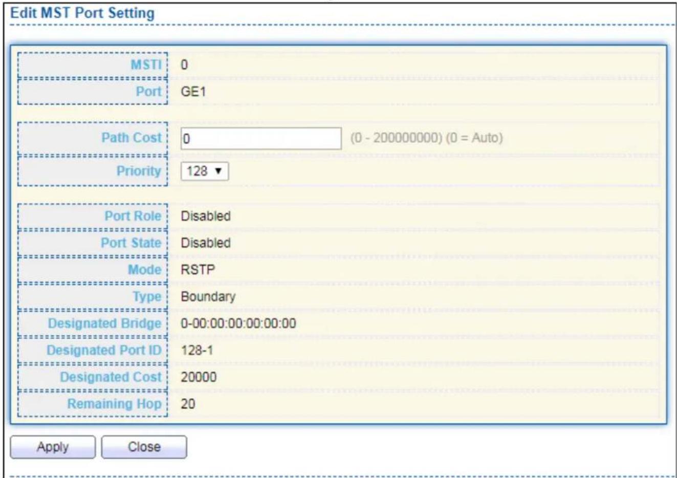
text_image
Edit MST Port Setting MSTI 0 Port GE1 Path Cost 0 (0 - 200000000) (0 = Auto) Priority 128 ▼ Port Role Disabled Port State Disabled Mode RSTP Type Boundary Designated Bridge 0-00:00:00:00:00:00 Designated Port ID 128-1 Designated Cost 20000 Remaining Hop 20 Apply CloseFigure 70 - Spanning Tree > MST Port Seng > Edit MST Port Seng
| Item | Descripon |
| Path Cost | Specify the STP port path cost on the specied MSTI. |
| Priority | Specify the STP port priority on the specied MSTI. |
IV-7-5 Stascs
To display the STP stascs, click STP > Stascs.

Figure 71 - Spanning Tree > Stascs
| Item | Descripon |
| Refresh Rate | The opon to refresh the stascs automacally. |
| Receive BPDU (Cong) | The counts of the received CONFIG BPDU. |
| Receive BPDU (TCN) | The counts of the received TCN BPDU. |
| Receive BPDU (MSTP) | The counts of the received MSTP BPDU. |
| Transmit BPDU (Cong) | The counts of the transmied CONFIG BPDU. |
| Transmit BPDU (TCN) | The counts of the transmied TCN BPDU. |
| Transmit BPDU (MSTP) | The counts of the transmied MSTP BPDU. |
| Clear | Clear the stascs for the selected interfaces |
| View | View the stascs for the interface. |
Click "View" buon to view the STP Port Stasc menu.

text_image
STP Port Statistic Port GE1 Refresh Rate None 5 sec 10 sec 30 sec Receive BPDU Config 0 TCN 0 MSTP 0 Transmit BPDU Config 0 TCN 0 MSTP 0 Refresh Clear CloseFigure 72 - Spanning Tree > Stascs > STP Port Stasc
| Item | Descripon |
| Refresh Rate | The opon to refresh the stascs automacally. |
| Clear | Clear the stascs for the selected interfaces. |
IV-8 Discovery
Use this secon to congure LLDP.
IV-8-1 LLDP
LLDP is a one-way protocol; there are no request/response sequences. Informa-on is adversed by staons implementing the transmit funcon, and is received and processed by staons implementing the receive funcon. The LLDP category contains LLDP and LLDP-MED pages.
IV-8-1-1 Property
To display LLDP Property Seng web page, click Discovery > LLDP > Property.
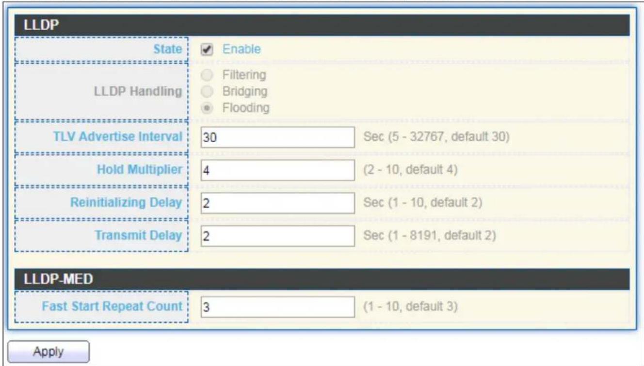
text_image
LLDP State Enable LLDP Handling Filtering Bridging Flooding TLV Advertise Interval 30 Sec (5 - 32767, default 30) Hold Multiplier 4 (2 - 10, default 4) Reinitializing Delay 2 Sec (1 - 10, default 2) Transmit Delay 2 Sec (1 - 8191, default 2) LLDP-MED Fast Start Repeat Count 3 (1 - 10, default 3) ApplyFigure 73 - Discovery > LLDP > Property
| Item | Descripon |
| State | Enable/ Disable LLDP protocol on this switch. |
| LLDP Handling | Select LLDP PDU handling acon to be Itered, bridging or ooded when LLDP is globally disabled.● Filtering: Deletes the packet.● Bridging: (VLAN-aware ooding) Forwards the packet to all VLAN members.● Flooding: Forwards the packet to all ports |
| TLV Adverse | Select the interval at which frames are transmied. The default is 30 |
| Interval | seconds, and the valid range is 5–32767 seconds. |
| HoldmeMulplier | Select the mulplier on the transmit interval to assign to TTL (range 2–10, default = 4). |
| ReinializaonDelay | Select the delay before a re-inializaon (range 1–10 seconds, default = 2). |
| Transmit Delay | Select the delay aer an LLDP frame is sent (range 1–8191 seconds, default = 3). |
| Fast Start Repeat Count | Select fast start repeat count when port link up (range 1–10, default = 3). |
IV-8-1-2 Port Seng
To display LLDP Port Seng, click Discovery > LLDP > Port Seng.
| Port Setting Table | ||||
| Entry | Port | Mode | Selected TLV | |
| 1 | GE1 | Normal | 802.1 PVID | |
| 2 | GE2 | Normal | 802.1 PVID | |
| 3 | GE3 | Normal | 802.1 PVID | |
| 4 | GE4 | Normal | 802.1 PVID | |
| 5 | GE5 | Normal | 802.1 PVID | |
| 6 | GE6 | Normal | 802.1 PVID | |
| 7 | GE7 | Normal | 802.1 PVID | |
| 8 | GE8 | Normal | 802.1 PVID | |
| 9 | GE9 | Normal | 802.1 PVID | |
| 10 | GE10 | Normal | 802.1 PVID | |
| 11 | GE11 | Normal | 802.1 PVID | |
| 12 | GE12 | Normal | 802.1 PVID | |
| 13 | GE13 | Normal | 802.1 PVID | |
| 14 | GE14 | Normal | 802.1 PVID | |
| 15 | GE15 | Normal | 802.1 PVID | |
| 16 | GE16 | Normal | 802.1 PVID | |
| 17 | GE17 | Normal | 802.1 PVID | |
| 18 | GE18 | Normal | 802.1 PVID | |
| 19 | GE19 | Normal | 802.1 PVID | |
| 20 | GE20 | Normal | 802.1 PVID | |
| 21 | GE21 | Normal | 802.1 PVID | |
| 22 | GE22 | Normal | 802.1 PVID | |
| 23 | GE23 | Normal | 802.1 PVID | |
| 24 | GE24 | Normal | 802.1 PVID | |
| 25 | GE25 | Normal | 802.1 PVID | |
| 26 | GE26 | Normal | 802.1 PVID | |
| 27 | GE27 | Normal | 802.1 PVID | |
| 28 | GE28 | Normal | 802.1 PVID | |
Figure 74 - Discovery > LLDP > Port Seng
| Item | Descripon |
| Port | Port Name. |
| Mode | The port LLDP mode. |
| Selectde TLV | The Selected LLDP TLV. |
Click "Edit" buon to view Edit Port Seng menu.

text_image
Edit Port Setting Port GE1 Transmit Receive Normal Disable Mode Optional TLV Available TLV Selected TLV Port Description System Name System Description System Capabilities 802.3 MAC-PHY 802.1 PVID 802.1 VLAN Name Available VLAN Selected VLAN VLAN 1 VLAN 2 Apply CloseFigure 75 - Discovery > LLDP > Port Seng > Edit Port Seng
| Item | Descripon |
| Port | Select specied port or all ports to congregate LLDP state. |
| Mode | Select the transmission state of LLDP port interface.● Disable: Disable the transmission of LLDP PDUs.● RX Only: Receive LLDP PDUs only.● TX Only: Transmit LLDP PDUs only.● TX And RX: Transmit and receive LLDP PDUs both. |
| Oponal TLV | Select the LLDP oponal TLVs to be carried (mulple selecon is allowed).● System Name● Port Descripon● System Descripon● System Capability● 802.3 MAC-PHY● 802.3 Link Aggregaon● 802.3 Maximum Frame Size● Management Address● 802.1 PVID. |
| 802.1 VLAN Name | Select the VLAN Name ID to be carried (mulple selecon is allowed). |
IV-8-1-3 Packet View
To display LLDP Overloading, click Discovery > LLDP > Packet View.
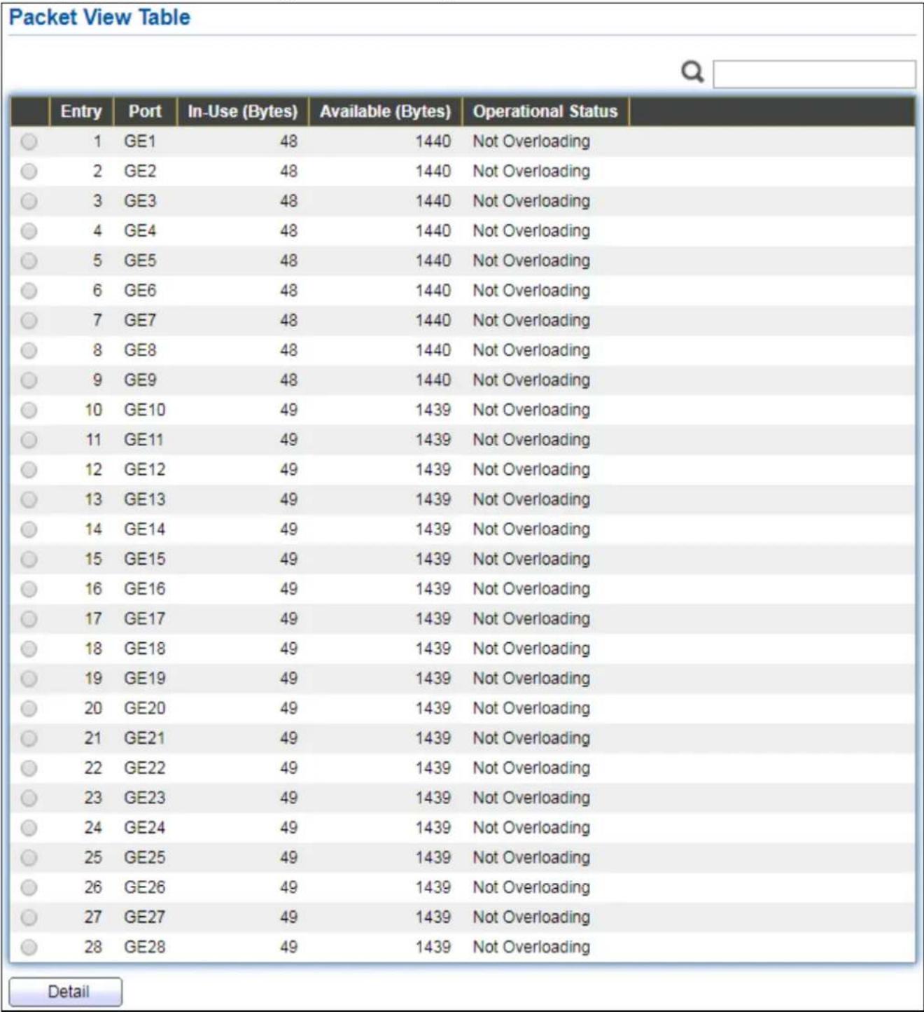
Figure 76 - Discovery > LLDP > Packet View
| Item | Descripon |
| Port | Port Name. |
| In-Use (Bytes) | Total number of bytes of LLDP informaon in each packet. |
| Available (Bytes) | Total number of available bytes le for additional LLDP informaon in each packet. |
| Operaonal Status | Overloading or not. |
Click "Detail" buon to view Packet View Detail menu.
| Packet View Detail | |
| Port | GE1 |
| Mandatory TLVs | |
| Size (Bytes) | 21 |
| Operational Status | Transmitted |
| MED Capabilities | |
| Size (Bytes) | 9 |
| Operational Status | Transmitted |
| MED Location | |
| Size (Bytes) | 0 |
| Operational Status | Transmitted |
| MED Network Policy | |
| Size (Bytes) | 10 |
| Operational Status | Transmitted |
| MED Inventory | |
| Size (Bytes) | 0 |
| Operational Status | Transmitted |
| MED Extended Power via MDI | |
| Size (Bytes) | 0 |
| Operational Status | Transmitted |
| 802.3 TLVs | |
| Size (Bytes) | 0 |
| Operational Status | Transmitted |
| Optional TLVs | |
| Size (Bytes) | 0 |
| Operational Status | Transmitted |
| 802.1 TLVs | |
| Size (Bytes) | 8 |
| Operational Status | Transmitted |
| Total | |
| In-Use (Bytes) | 48 |
| Available (Bytes) | 1440 |
Figure 77 - Discovery > LLDP > Packet View > Packet View Detail
| Item | Descripon |
| Port | Port Name. |
| Mandatory TLVs | Total mandatory TLV byte size. Status is sent or overloading. |
| MED Capabilities | Total MED Capabilities TLV byte size. Status is sent or overloading. |
| MED Locaon | Total MED Locaon byte size. Status is sent or overloading. |
| MED Network Policy | Total MED Network Policy byte size. Status is sent or overloading. |
| MED Inventory | Total MED Inventory byte size. Status is sent or overloading |
| MED Extended Power via MDI | Total MED Extended Power via MDI byte size. Status is sent or overloading. |
| 802.3 TLVs | Total 802.3 TLVs byte size. Status is sent or overloading. |
| Oponal TLVs | Total Oponal TLV byte size. Status is sent or overloading. |
| 802.1 TLVs | Total 802.1 TLVs byte size. Status is sent or overloading. |
| Total | Total number of bytes of LLDP informaon in each packet. |
IV-8-1-4 Local Informaon
Use the LLDP Local Informaon to view LLDP local device informaon.
To display LLDP Local Device, click Discovery > LLDP > Local Informaon.
Device Summary
| Chassis ID Subtype | MAC address |
| Chassis ID | 74:DA:38:17:6E:7A |
| System Name | Switch |
| System Description | 24-Port Gigabit PoE+ Smart Managed Switch with 4 RJ45/SFP Combo Ports |
| Supported Capabilities | Bridge |
| Enabled Capabilities | Bridge |
| Port ID Subtype | Local |
Port Status Table

| Entry | Port | LLDP State | LLDP-MED State | |
| ○ | 1 | GE1 | Normal | Enabled |
| ○ | 2 | GE2 | Normal | Enabled |
| ○ | 3 | GE3 | Normal | Enabled |
| ○ | 4 | GE4 | Normal | Enabled |
| ○ | 5 | GE5 | Normal | Enabled |
| ○ | 6 | GE6 | Normal | Enabled |
| ○ | 7 | GE7 | Normal | Enabled |
| ○ | 8 | GE8 | Normal | Enabled |
| ○ | 9 | GE9 | Normal | Enabled |
| ○ | 10 | GE10 | Normal | Enabled |
| ○ | 11 | GE11 | Normal | Enabled |
| ○ | 12 | GE12 | Normal | Enabled |
| ○ | 13 | GE13 | Normal | Enabled |
| ○ | 14 | GE14 | Normal | Enabled |
| ○ | 15 | GE15 | Normal | Enabled |
| ○ | 16 | GE16 | Normal | Enabled |
| ○ | 17 | GE17 | Normal | Enabled |
| ○ | 18 | GE18 | Normal | Enabled |
| ○ | 19 | GE19 | Normal | Enabled |
| ○ | 20 | GE20 | Normal | Enabled |
| ○ | 21 | GE21 | Normal | Enabled |
| ○ | 22 | GE22 | Normal | Enabled |
| ○ | 23 | GE23 | Normal | Enabled |
| ○ | 24 | GE24 | Normal | Enabled |
| ○ | 25 | GE25 | Normal | Enabled |
| ○ | 26 | GE26 | Normal | Enabled |
| ○ | 27 | GE27 | Normal | Enabled |
| ○ | 28 | GE28 | Normal | Enabled |
Detail
Figure 78 - Discovery > LLDP > Local Informaon
| Item | Descripon |
| Chassis ID Subtype | Type of chassis ID, such as the MAC address. |
| Chassis ID | Idener of chassis. Where the chassis ID subtype is a MAC address, the MAC address of the switch is displayed. |
| System Name | Name of switch. |
| System Descripon | Descripon of the switch. |
| Capabilities | Primary funcons of the device, such as Bridge, WLAN AP, or Router. |
| Supported | |
| Capabilities Enabled | Primary enabled funcons of the device. |
| Port ID Subtype | Type of the port idener that is shown. |
| LLDP Status | LLDP Tx and Rx abilities. |
| LLDP Med Status | LLDP MED enable state. |
Click "Detail" buon on the page to view detail informaon of the selected port.
| Chassis ID Subtype | MAC address | |
| Chassis ID | 74:DA:38:17:6E:7A | |
| System Name | Switch | |
| System Description | 24-Port Gigabit PoE+ Smart Managed Switch with 4 RJ45/SFP Combo Ports | |
| Supported Capabilities | Bridge | |
| Enabled Capabilities | Bridge | |
| Port ID | GE1 | |
| Port ID Subtype | Local | |
| Port Description | ||
| Management Address Table | ||
| Address Subtype | Address Interface Subtype Interface Number | |
| 0 results found. | ||
| MAC/PHY Detail | ||
| Auto-Negotiation Supported | N/A | |
| Auto-Negotiation Enabled | N/A | |
| Auto-Negotiation Advertised Capabilities | N/A | |
| Operational MAU Type | N/A | |
| 802.3 Detail | ||
| 802.3 Maximum Frame Size | N/A | |
| 802.3 Link Aggregation | ||
| Aggregation Capability | N/A | |
| Aggregation Status | N/A | |
| Aggregation Port ID | N/A | |
| MED Detail | ||||
| Capabilities Supported | Capabilities, Network policy | |||
| Current Capabilities | Capabilities, Network policy | |||
| Device Class | Network Connectivity | |||
| PoE Device Type | N/A | |||
| PoE Power Source | N/A | |||
| PoE Power Priority | N/A | |||
| PoE Power Value | N/A | |||
| Hardware Revision | N/A | |||
| Firmware Revision | N/A | |||
| Software Revision | N/A | |||
| Serial Number | N/A | |||
| Manufacturer Name | N/A | |||
| Model Name | N/A | |||
| Asset ID | N/A | |||
| Location Information | ||||
| Civic | N/A | |||
| Coordinate | N/A | |||
| ECS ELIN | N/A | |||
| Network Policy Table | ||||
| Application Type | VLAN | VLAN Type | Priority | DSCP |
| 0 results found. | ||||
| Close | ||||
Figure 79 - Discovery > LLDP > Local Informaon > Detail
IV-8-1-5 Neighbor
Use the LLDP Neighbor page to view LLDP neighbors informaon.
To display LLDP Remote Device, click Discovery > LLDP > Neighbor.

text_image
Neighbor Table Showing All entries Showing 0 to 0 of 0 entries Local Port Chassis ID Subtype Chassis ID Port ID Subtype Port ID System Name Time to Live 0 results found. Clear Refresh Detail First Previous 1 Next LastFigure 80 - Discovery > LLDP > Neighbor
| Item | Descripon |
| Local Port | Number of the local port to which the neighbor is connected. |
| Chassis ID Subtype | Type of chassis ID (for example, MAC address). |
| Port ID Subtype | Type of the port idener that is shown. |
| Port ID | Idener of port. |
| System Name | Published name of the switch. |
| Time to Live | Time interval in seconds aer which the informaon for this neighbor is deleted. |
Click "detail" to view selected neighbor detail informaon
| Local Port | |||
| Basic Detail | |||
| Chassis ID Subtype | Unknown | ||
| Chassis ID | |||
| Port ID Subtype | Unknown | ||
| Port ID | |||
| Port Description | |||
| System Name | |||
| System Description | |||
| Supported Capabilities | N/A | ||
| Enabled Capabilities | N/A | ||
| Management Address Table | |||
| Address Subtype | Address | Interface Subtype | Interface Number |
| 0 results found. | |||
| MAC/PHY Detail | |||
| Auto-Negotiation Supported | N/A | ||
| Auto-Negotiation Enabled | N/A | ||
| Auto-Negotiation Advertised Capabilities | N/A | ||
| Operational MAU Type | N/A | ||
| 802.3 Power via MDI | |||
| MDI Power Support Port Class | N/A | ||
| PSE MDI Power Support | N/A | ||
| PSE MDI Power State | N/A | ||
| PSE Power Pair Control Ability | N/A | ||
| PSE Power Pair | N/A | ||
| PSE Power Class | N/A | ||
| Power Type | N/A | ||
| Power Source | N/A | ||
| Power Priority | N/A | ||
| PD Request Power Value | N/A | ||
| PSE Allocated Power Value | N/A | ||
| 802.3 Detail | |||
| 802.3 Maximum Frame Size | N/A | ||
| 802.3 Link Aggregation | ||||
| Aggregation Capability | N/A | |||
| Aggregation Status | N/A | |||
| Aggregation Port ID | N/A | |||
| 802.1 VLAN and Protocol | ||||
| PVID | ||||
| VLAN Name | N/A | |||
| MED Detail | ||||
| Capabilities Supported | N/A | |||
| Current Capabilities | N/A | |||
| Device Class | N/A | |||
| PoE Device Type | N/A | |||
| PoE Power Source | N/A | |||
| PoE Power Priority | N/A | |||
| PoE Power Value | N/A | |||
| Hardware Revision | N/A | |||
| Firmware Revision | N/A | |||
| Software Revision | N/A | |||
| Serial Number | N/A | |||
| Manufacturer Name | N/A | |||
| Model Name | N/A | |||
| Asset ID | N/A | |||
| Location Information | ||||
| Civic | N/A | |||
| Coordinate | N/A | |||
| ECS ELIN | N/A | |||
| Network Policy Table | ||||
| Application Type | VLAN | VLAN Type | Priority | DSCP |
| 0 results found. | ||||
| Close | ||||
Figure 81 - LLDP Neighbor Detail Page
IV-8-1-6 Stascs
The Link Layer Discovery Protocol (LLDP) Stascs page displays summary and per-port informaon for LLDP frames transmied and received on the switch.
To display LLDP Stascs status, click Discovery > LLDP > Stascs.
| Global Statistics | ||||||||||
| Insertions 0 | ||||||||||
| Deletions 0 | ||||||||||
| Drops 0 | ||||||||||
| AgeOuts 0 | ||||||||||
| Clear Refresh | ||||||||||
| Statistics Table Q ■ | Entry | Port | Transmit Frame | Receive Frame | Receive TLV | Neighbor Timeout | ||||
| Total | Total | Discard | Error | Discard | Unrecognized | |||||
| □ | 1 | GE1 | 0 | 0 | 0 | 0 | 0 | 0 | 0 | |
| □ | 2 | GE2 | 0 | 0 | 0 | 0 | 0 | 0 | 0 | |
| □ | 3 | GE3 | 0 | 0 | 0 | 0 | 0 | 0 | 0 | |
| □ | 4 | GE4 | 0 | 0 | 0 | 0 | 0 | 0 | 0 | |
| □ | 5 | GE5 | 0 | 0 | 0 | 0 | 0 | 0 | 0 | |
| □ | 6 | GE6 | 0 | 0 | 0 | 0 | 0 | 0 | 0 | |
| □ | 7 | GE7 | 0 | 0 | 0 | 0 | 0 | 0 | 0 | |
| □ | 8 | GE8 | 0 | 0 | 0 | 0 | 0 | 0 | 0 | |
| □ | 9 | GE9 | 0 | 0 | 0 | 0 | 0 | 0 | 0 | |
| □ | 10 | GE10 | 0 | 0 | 0 | 0 | 0 | 0 | 0 | |
| □ | 11 | GE11 | 0 | 0 | 0 | 0 | 0 | 0 | 0 | |
| □ | 12 | GE12 | 0 | 0 | 0 | 0 | 0 | 0 | 0 | |
| □ | 13 | GE13 | 0 | 0 | 0 | 0 | 0 | 0 | 0 | |
| □ | 14 | GE14 | 0 | 0 | 0 | 0 | 0 | 0 | 0 | |
| □ | 15 | GE15 | 0 | 0 | 0 | 0 | 0 | 0 | 0 | |
| □ | 16 | GE16 | 0 | 0 | 0 | 0 | 0 | 0 | 0 | |
| □ | 17 | GE17 | 0 | 0 | 0 | 0 | 0 | 0 | 0 | |
| □ | 18 GE18 19 GE19 20 GE20 21 GE21 22 GE22 23 GE23 24 GE24 25 GE25 26 GE26 27 GE27 28 GE28 512 0 0 512 0 512 512 512 512 512 512 512 512 512 512 512 512 512 512 512 512 512 512 512 512 512 512 512 512 512 513 513 513 513 513 513 513 513 513 513 513 513 513 513 513 513 513 513 513 513 513 513 513 513 513 514 514 514 514 514 514 514 514 514 514 514 514 514 514 514 514 514 514 514 514 514, □ Clear Refresh | |||||||||
Figure 82 - Discovery > LLDP > Stascs
| Item | Descripon |
| Inserons | The number of mes the complete set of informaon adversed by a parcular MAC Service Access Point (MSAP) has been inserted into tables associated with the remote systems. |
| Deleons | The number of mes the complete set of informaon adversed by MSAP has been deleted from tables associated with the remote systems. |
| Drops | The number of mes the complete set of informaon adversed by MSAP could not be entered into tables associated with the remote systems because of insucient resources. |
| Age Outs | The number of mes the complete set of informaon adversed by MSAP has been deleted from tables associated with the remote systems because the informaon meliness interval has expired. |
| Stascs Table | |
| Port | Interface or port number. |
| Transmit Frame Total | Number of LLDP frames transmied on the corresponding port. |
| Receive Frame Total | Number of LLDP frames received by this LLDP agent on the corresponding port, while the LLDP agent is enabled. |
| Receive Frame Discard | Number of LLDP frames discarded for any reason by the LLDP agent on the corresponding port. |
| Receive Frame Error | Number of invalid LLDP frames received by the LLDP agent on the corresponding port, while the LLDP agent is enabled. |
| Receive TLV Discard | Number of TLVs of LLDP frames discarded for any reason by the LLDP agent on the corresponding port. |
| Receive TLV Unrecognized | Number of TLVs of LLDP frames that are unrecognied while the LLDP agent is enabled. |
| Neighbor Timeout | Number of age out LLDP frames. |
IV-9 Mulcast
Use this secon to congure Mulcast.
IV-9-1 General
Use the General pages to congregate sengs of IGMP and MLD common funcon.
IV-9-1-1 Property
To display mulcast general property Seng web page, click Mulcast> General> Property.

text_image
Unknown Multicast Action Flood Drop Forward to Router Port Multicast Forward Method IPv4 DMAC-VID DIP-VID IPv6 DMAC-VID DIP-VID ApplyFigure 83 - Mulcast > General > Property
| Item | Descripon |
| Unknown Mulcast Acon | Set the unknown mulcast acon● Flood: ood the unknown mulcast data.● Drop: drop the unknown mulcast data.● Router port: forward the unknown mulcast data to router port. |
| IPv4 | Set the ipv4 mulcast forward method.● MAC-VID: forward method dmac+vid.● DIP-VID: forward method dip+vid. |
| IPv6 | Set the ipv6 multicast forward method.● MAC- VID: forward method dmac+vid.● DIP-VID: forward method dip+vid(dip is ipv6 low 32 bit). |
IV-9-1-2 Group Address
This page allows user to browse all mulcast groups that dynamic learned or stacally added.
To display Mulcast General Group web page, click Mulcast> General > Group Address.
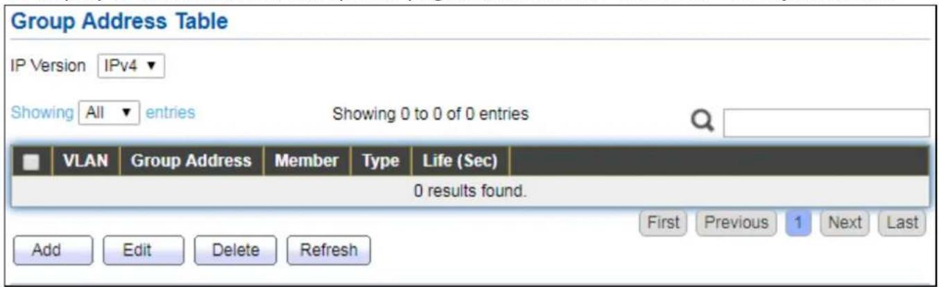
text_image
Group Address Table IP Version IPv4 ▼ Showing All entries Showing 0 to 0 of 0 entries VLAN Group Address Member Type Life (Sec) 0 results found. Add Edit Delete Refresh First Previous 1 Next LastFigure 84 - Mulcast > General > Group Address
| Item | Descripon |
| IP Version | IP Version● IPv4: ipv4 mulcast group● IPv6: ipv6 mulcast group |
| VLAN | The VLAN ID of group. |
| Group Address | The group IP address. |
| Member | The member ports of group. |
| Type | The type of group. Stac or Dynamic. |
| Life(Sec) | The life me of this dynamic group. |
Click "Add" or "Edit" buon to view Add or Edit Group Address menu.
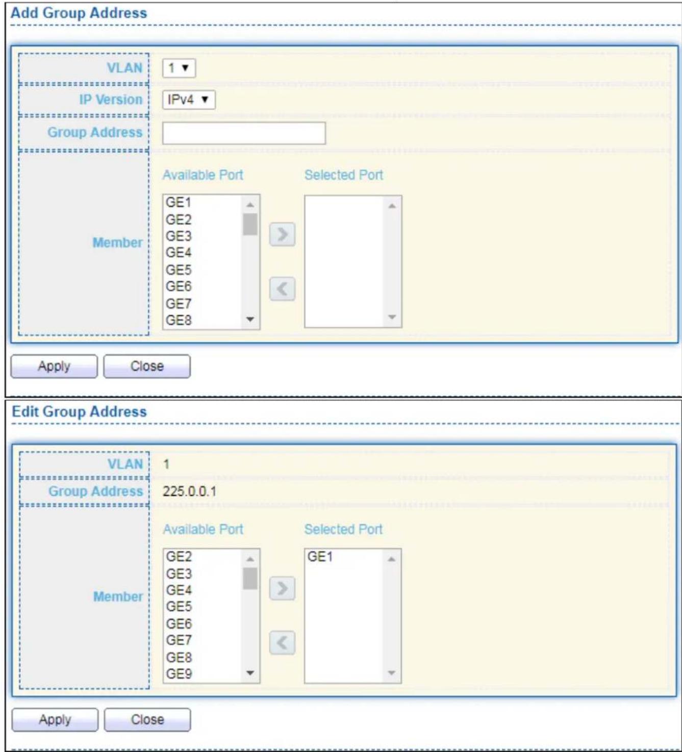
text_image
Add Group Address VLAN 1 IP Version IPv4 Group Address Member Available Port Selected Port GE1 GE2 GE3 GE4 GE5 GE6 GE7 GE8 Apply Close Edit Group Address VLAN 1 Group Address 225.0.0.1 Member Available Port Selected Port GE2 GE3 GE4 GE5 GE6 GE7 GE8 GE9 GE1 Apply CloseFigure 85 - Mulcast > General > Group Address > Add/Edit Group Address
| Item | Descripon |
| VLAN | The VLAN ID of group. |
| IP Version | IP Version● IPv4: ipv4 mulcast group● IPv6: ipv6 mulcast group |
| Group Address | The group IP address. |
| Member | The member ports of group. |
● Available Port: Oponal port member
- Selected Port: Selected port member
IV-9-1-3 Router Port
This page allows user to browse all router port informaon. The stac and forbidden router port can set by user.
To display mulcast router port table web page, click Mulcast > General > Router Port.

text_image
Router Port Table IP Version IPv4 ▼ Showing All entries Showing 0 to 0 of 0 entries VLAN Member Static Port Forbidden Port Life (Sec) 0 results found. Add Edit Refresh First Previous 1 Next LastFigure 86 - Mulcast > General > Router Port
| Item | Descripon |
| IP Version | IP Version● IPv4: ipv4 mulcast router● IPv6: ipv6 mulcast router |
| VLAN | The VLAN ID router entry. |
| Member | Router Port member (include stac and learned port member). |
| Stac Port | Stac router port member. |
| Forbidden Port | Forbidden router port member. |
| Life (Sec) | The expiry me of the router entry. |
Click "Add" or "Edit" buon to view Add/Edit Router Port menu.
Add Router Port
VLAN
Available VLAN

natural_image
Blank white rectangle with a numbered corner and two small triangular shapes on the right side (no text or symbols)Selected VLAN


natural_image
Blank white rectangle with a thin gray border and two small triangular markers on the right side (no text or symbols)IP Version
IPv4 ▼
Type
Static Forbidden
Port
Available Port

text_image
GE1 GE2 GE3 GE4 GE5 GE6 GE7 GE8Selected Port


natural_image
Blank white rectangle with two small triangular markers on the right side (no text or symbols)Apply
Close
Edit Router Port
VLAN
IP Version
Type
Port
1
IPv4

Static Forbidden
Available Port

text_image
GE2 GE3 GE4 GE5 GE6 GE7 GE8 GE9Selected Port


text_image
GE1Apply
Close
Figure 87 - Mulcast > General > Router Port > Add/Edit Router Port
| Item | Descripon |
| VLAN | The VLAN ID for router entry● Available VLAN: Oponal VLAN member● Selected VLAN: Selected VLAN member. |
| IP Version | IP Version● IPv4: ipv4 mulcast router● IPv6: ipv6 mulcast router |
| Type | The router port type● Stac: stac router port● Forbidden: forbidden router port, can’t learn dynamic router port member |
| Port | The member ports of router entry.● Available Port: Oponal router port member● Selected Port: Selected router port member |
IV-9-2 IGMP Snooping
Use the IGMP Snooping pages to congregate sengs of IGMP snooping funcon.
IV-9-2-1 Property
This page allows user to congregate global sengs of IGMP snooping and congregate specific VLAN sengs of IGMP Snooping.
To display IGMP Snooping global seng and VLAN Seng web page, click Mulcast > IGMP Snooping > Property.

text_image
State Enable Version IGMPv2 IGMPv3 Report Suppression Enable Apply VLAN Setting Table VLAN Operational Status Router Port Query Query Query Max Last Member Last Member Immediate Leave Auto Learn Auto Robustness Interval Response Interval Query Counter Query Interval Disabled Enabled 2 125 10 2 1 Disabled EditFigure 88 - Mulcast > IGMP Snooping > Property
| Item | Descripon |
| State | Set the enabling status of IGMP Snooping funconalityEnable: If Checked Enable IGMP Snooping, else is Disabled IGMP Snooping. |
| Version | Set the igmp snooping versionIGMPv2: Only support process igmp v2 packet.IGMPv3: Support v3 basic and v2. |
| Report Suppression | Set the enabling status of IGMP v2 report suppressionEnable: If Checked Enable IGMP Snooping v2 report suppression, else Disable the report suppression funcon. |
| VLAN | The IGMP entry VLAN ID. |
| Operaon Status | The enable status of IGMP snooping VLAN funconality. |
| Router Port Auto Learn | The enabling status of IGMP snooping router port auto learning. |
| Query Robustness | The Query Robustness allows tuning for the expected packet loss on a subnet. |
| Query Interval | The interval of querier to send general query. |
| Query Max Response Interval | In Membership Query Messages, it species the maximum allowed me before sending a responding report in units of 1/10 second. |
| Last Member Query count | The count that Querier-switch sends Group-Specic Queries when it receives a Leave Group message for a group. |
| Last Member Query Interval | The interval that Querier-switch sends Group-Specic Queries when it receives a Leave Group message for a group. |
| Immediate leave | The immediate leave status of the group will immediate leave when receive IGMP Leave message. |
Click "Edit" buon to Edit VLAN Seng menu.
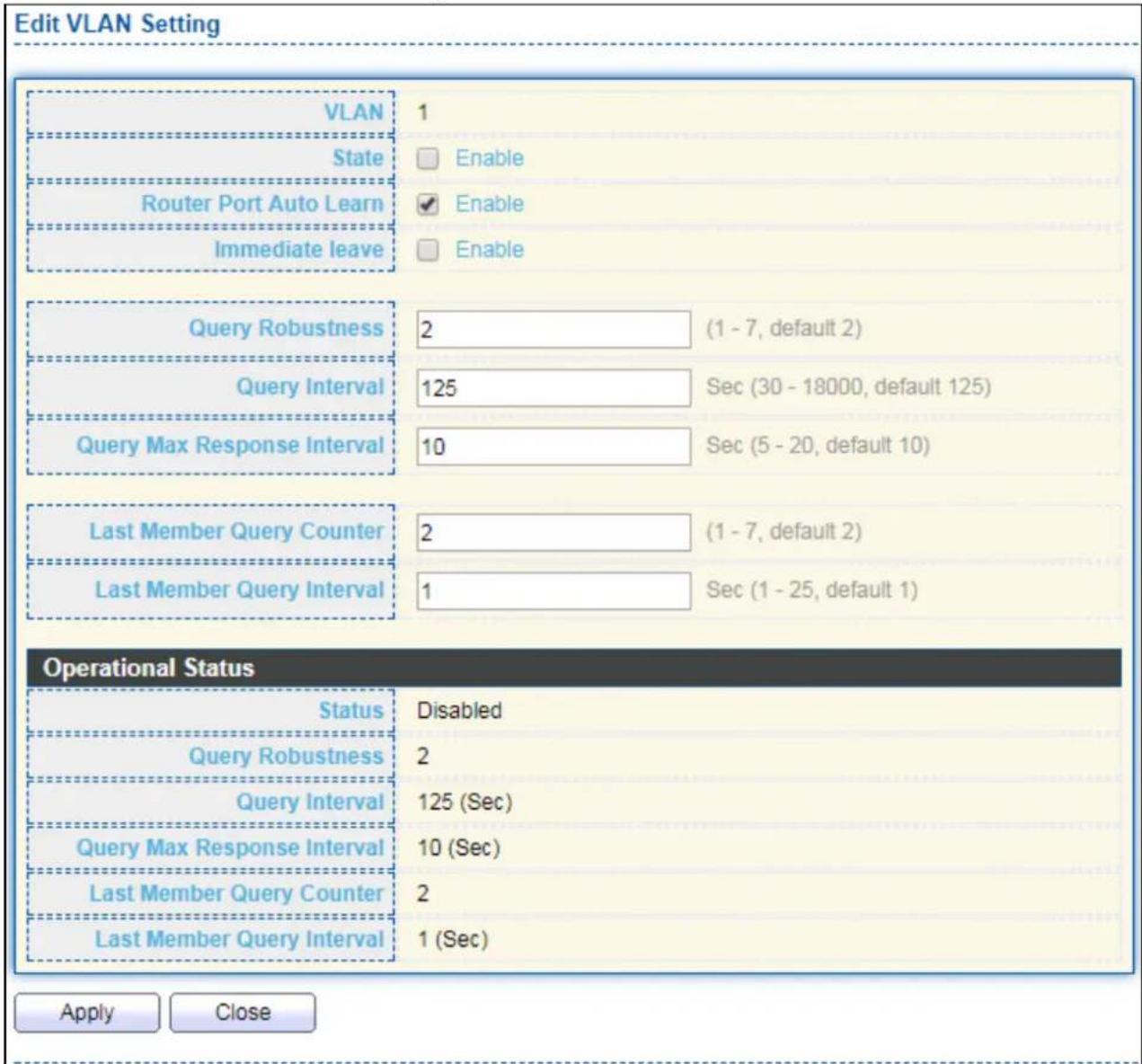
text_image
Edit VLAN Setting VLAN 1 State Enable Router Port Auto Learn Enable Immediate leave Enable Query Robustness 2 (1 - 7, default 2) Query Interval 125 Sec (30 - 18000, default 125) Query Max Response Interval 10 Sec (5 - 20, default 10) Last Member Query Counter 2 (1 - 7, default 2) Last Member Query Interval 1 Sec (1 - 25, default 1) Operational Status Status Disabled Query Robustness 2 Query Interval 125 (Sec) Query Max Response Interval 10 (Sec) Last Member Query Counter 2 Last Member Query Interval 1 (Sec) Apply CloseFigure 89 - Mulcast > IGMP Snooping > Property > Edit VLAN Seng
| Item | Descripon |
| VLAN | The selected VLAN List. |
| State | Set the enabling status of IGMP Snooping VLAN funconalityEnable: If Checked Enable IGMP Snooping VLAN, else is Disabled IGMP Snooping VLAN. |
| Router Port Auto Learn | Set the enabling status of IGMP Snooping router port learningEnable: If checked Enable learning router port by query and PIM, DVRMP, else Disable the learning router port. |
| Immediate leave | Immediate Leave the group when receive IGMP Leave message.Enable: If checked Enable immediate leave, else disable immediate leave. |
| Query Robustness | The Admin Query Robustness allows tuning for the expected packet loss on a subnet. |
| Query Interval | The Admin interval of querier to send general query. |
| Query Max Response Interval | The Admin query max response interval, In Membership Query Messages, it species the maximum allowed me before sending a responding report in units of 1/10 second. |
| Last Member Query Counter | The Admin last member query count that Querier-switch sends Group-Specic Queries when it receives a Leave Group message for a group. |
| Last Member Query Interval | The Admin last member query interval that Querier-switch sends Group-Specic Queries when it receives a Leave Group message for a group. |
| Operational Status | |
| Status | Operational IGMP snooping status, must both IGMP snooping global and IGMP snooping enable the status will be enable. |
| Query Robustness | Operational Query Robustness. |
| Query Interval | Operational Query Interval. |
| Query Max Response Interval | Operational Query Max Response Interval |
| Last Member Query Counter | Operational Last Member Query Count. |
| Last Member Query Interval | Operational Last Member Query Interval. |
IV-9-2-2 Querier
This page allows user to congregate queryer sengs on specific VLAN of IGMP Snooping.
To display IGMP Snooping Querier Seng web page, click Mulcast > IGMP Snooping > Querier.

text_image
Querier Table VLAN State Operational Status Version Querier Address 1 Disabled Disabled EditFigure 90 - Mulcast > IGMP Snooping > Querier
| Item | Descripon |
| VLAN | IGMP Snooping querier entry VLAN ID. |
| State | The IGMP Snooping querier Admin State. |
| Operaonal Status | The IGMP Snooping querier operaonal status. |
| Querier Version | The IGMP Snooping querier operaonal version. |
| Querier IP | The operaonal Querier IP address on the VLAN. |
Click "Edit" buon to view Edit Querier menu.

text_image
Edit Querier VLAN 1 State Enable Version IGMPv2 IGMPv3 Apply CloseFigure 91 - Mulcast > IGMP Snooping > Querier > Edit Querier
| Item | Descripon |
| VLAN | The Selected Edit IGMP Snooping querier VLAN List. |
| State | Set the enabling status of IGMP Querier Elecon on the chose VLANsEnabled: if checked Enable IGMP Querier else Disable IGMP Querier. |
| Version | Set the query version of IGMP Querier Elecon on the chose VLANsIGMPv2: Querier version 2.IGMPv3: Querier version 3. (IGMP Snooping version should be IGMPv3) |
IV-9-2-3 Stascs
This page allows user to clear IGMP snooping stacs.
To display IGMP Snooping Stascs, click Mulcast > IGMP Snooping > Stascs.
| Receive Packet | |
| Total | 91 |
| Valid | 8 |
| InValid | 83 |
| Other | 0 |
| Leave | 0 |
| Report | 0 |
| General Query | 0 |
| Special Group Query | 0 |
| Source-specific Group Query | 0 |
| Transmit Packet | |
| Leave | 0 |
| Report | 0 |
| General Query | 0 |
| Special Group Query | 0 |
| Source-specific Group Query | 0 |
| Clear Refresh | |
Figure 92 - Mulcast > IGMP Snooping > Stascs
| Item | Descripon |
| Receive Packet | |
| Total | Total RX igmp packet, include ipv4 mulcast data to CPU. |
| Valid | The valid igmp snooping process packet. |
| InValid | The invalid igmp snooping process packet. |
| Other | The ICMP protocol is not 2, and is not ipv4 mulcast data packet. |
| Leave | IGMP leave packet. |
| Report | IGMP join and report packet. |
| General Query | IGMP General Query packet. |
| Special Group Query | IGMP Special Group General Query packet. |
| Source-specific | IGMP Special Source and Group General Query packet. |
| Group Query | |
| Transmit Packet | |
| Leave | IGMP leave packet |
| Report | IGMP join and report packet |
| General Query | IGMP general query packet include querier transmit general query packet. |
| Special Group Query | IGMP special group query packet include querier transmit special group query packet. |
| Source-specific Group Query | IGMP Special Source and Group General Query packet. |
IV-9-3 MVR
Use the MVR pages to congregate sengs of MVR funcon.
IV-9-3-1 Property
To display mulcast MVR property Seng web page, click Mulcast > MVR > Property.
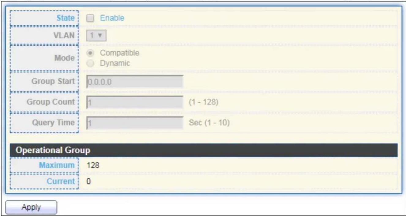
text_image
State Enable VLAN 1 Mode Compatible Dynamic Group Start 0.0.0.0 Group Count 1 (1 - 128) Query Time 1 Sec (1 - 10) Operational Group Maximum 128 Current 0 ApplyFigure 93 - Mulcast > MVR > Property
| Item | Descripon |
| State | Enable: if checked enable the MVR state, else disable the MVR state. |
| VLAN | The MVR VLAN ID. |
| Mode | Set the MVR mode● Compatible: compatible mode.● Dynamic: learn group member on source port. |
| Group Start | MVR group range start. |
| Group Count | MVR group connue count. |
| Query Time | MVR query me when receive MVR leave MVR group packet. |
| Maximum | The max number of MVR group database. |
| Current | The learned MVR group current me |
IV-9-3-2 Port Seng
This page allows user to congregate port role and port immediate leave.
To display MVR port role and immediate leave state seng web page, click Mulcast >MVR >Port Seng.
| Entry | Port | Role | Immediate Leave |
| 1 | GE1 | None | Disabled |
| 2 | GE2 | None | Disabled |
| 3 | GE3 | None | Disabled |
| 4 | GE4 | None | Disabled |
| 5 | GE5 | None | Disabled |
| 6 | GE6 | None | Disabled |
| 7 | GE7 | None | Disabled |
| 8 | GE8 | None | Disabled |
| 9 | GE9 | None | Disabled |
| 10 | GE10 | None | Disabled |
| 11 | GE11 | None | Disabled |
| 12 | GE12 | None | Disabled |
| 13 | GE13 | None | Disabled |
| 14 | GE14 | None | Disabled |
| 15 | GE15 | None | Disabled |
| 16 | GE16 | None | Disabled |
| 17 | GE17 | None | Disabled |
| 18 | GE18 | None | Disabled |
| 19 | GE19 | None | Disabled |
| 20 | GE20 | None | Disabled |
| 21 | GE21 | None | Disabled |
| 22 | GE22 | None | Disabled |
| 23 | GE23 | None | Disabled |
| 24 | GE24 | None | Disabled |
| 25 | GE25 | None | Disabled |
| 26 | GE26 | None | Disabled |
| 27 | GE27 | None | Disabled |
| 28 | GE28 | None | Disabled |
| 29 | LAG1 | None | Disabled |
| 30.0.0.0.0.0.0.0.0.0.0.0.0.0.0.0.0.0.0.0.0.0.0.0.0.0.0.0.0.0.0.0.0.0.0.0.0.0.0.0.0.0.0.0.0.0.0.0.0.0.0 0.0.0.0.0.0.0.0.0.0.0.0.0.0.0.0.0.0.0.0.0.0.0.0.0.0.0.0.0.0.0.0.0 0.0.0.0.0.0.0.0.0.0.0.0.0.0.0.0.0 0.0.0.0.0.0.0.0.0.0.0.0.0.0 0.0.0.0.0.0.0.0.0.0.0.0 0.0, 1, 2, 3, 4, 5, 6, 7, 8, 9, 10, 11, 12, 13, 14, 15, 16, 17, 18, 19, 20, 21, 22, 23, 24, 25, 26, 27, 28, 29, 30, 31, 32, 33, 34, 35, 36, 37, 38, 39, 40, 41, 42, 43, 44, 45, 46, 47, 48, 49, 50, 51, 52, 53, 54, 55, 56, 57, 58, 59, 60, 61, 62, 63, 64, 65, 66, 67, 68, 69, 70, 71, 72, 73, 74, 75, 76, 77, 78, 79, 80, 81, 82, 83, 84, 85, 86, 87, 88, 89, 90, 91, 92, 93, 94, 95, 96, 97, 98, 99, 100 |
Figure 94 - Mulcast > MVR > Port Seng
| Item | Descripon |
| Entry | Entry of number. |
| Port | Port Name. |
| Role | Port Role for MVR, the type is None/Receiver/Source. |
| Immediate Leave | Status of immediate leave. |
Click "Edit" buon to view Edit Port Seng menu.

text_image
Edit Port Setting Port GE1 Role None Receiver Source Immediate Leave Enable Apply CloseFigure 95 - Mulcast > MVR > Port Seng > Edit Port Seng
| Item | Descripon |
| Port | Display the selected port list. |
| Role | MVR port role● None: port role is none.● Receiver: port role is receiver.● Source: port role is source. |
| Immediate Leave | MVR Port immediate leaveEnable: if checked is enable immediate leave, else disable immediate leave. |
IV-9-3-3 Group Address
This page allows user to browse all mulcast MVR groups that dynamic learned or stacally added.
To display Mulcast MVR Group web page, click Mulcast > MVR > Group Address.

text_image
Group Address Table Showing All entries Showing 0 to 0 of 0 entries VLAN Group Address Member Type Life (Sec) 0 results found. Add Edit Delete Refresh First Previous 1 Next LastFigure 96 - Mulcast > MVR > Group Address
| Item | Descripon |
| VLAN | The VLAN ID of MVR group. |
| Group Address | The MVR group IP address. |
| Member | The member ports of MVR group. |
| Type | The type of MVR group. Stac or Dynamic. |
| Life(Sec) | The life me of this dynamic MVR group. |
Click "Add" buon to view Add/Edit Group Address Table menu.

text_image
Add Group Address VLAN 1 Group Address (0.0.0.0 - 0.0.0.0) Member Available Port Selected Port Apply CloseFigure 97 - Mulcast > MVR > Group Address > Add Group Address
| Item | Descripon |
| VLAN | The VLAN ID of MVR group. |
| Group Address | The MVR group IP address. |
| Member | The member ports of MVR group.● Available Port: Oponal port member, it is only receiver port when MVR mode is compatible, it include source port when mode is dynamic.● Selected Port: Selected port member |
IV-10 Security
Use the Security pages to congregate sengs for the switch security features.
IV-10-1 RADIUS
This page allows user to add, edit or delete RADIUS server sengs and modify default parameter of RADIUS server.
To display RADIUS web page, click Security > RADIUS.

text_image
Use Default Parameter Retry 3 (1 - 10, default 3) Timeout 3 Sec (1 - 30, default 3) Key String Apply RADIUS Table Showing All entries Showing 0 to 0 of 0 entries Server Address Server Port Priority Retry Timeout Usage 0 results found. Add Edit Delete First Previous 1 Next LastFigure 98 - Security > RADIUS
| Item | Descripon |
| Retry | Set default retry number. |
| Timeout | Set default meout value. |
| Key String | Set default RADIUS key string |
| RADIUS Table | |
| Server Address | RADIUS server address. |
| Server Port | RADIUS server port. |
| Priority | RADIUS server priority (smaller value has higher priority). RADIUS session will try to establish with the server seng which has highest priority. If failed, it will try to connect to the server with next higher priority. |
| Retry | RADIUS server retry value. If it is fail to connect to server, it will keep trying unl meout with retry mes. |
| Timeout | RADIUS server meout value. If it is fail to connect to server, it willkeep trying unl meout. |
| Usage | RADIUS server usage typeLogin: For login authenfaon.802.1x: For 802.1x authencaon.All: For all types. |
Click "Add" or "Edit" buon to view Add/Edit RADIUS Server menu.
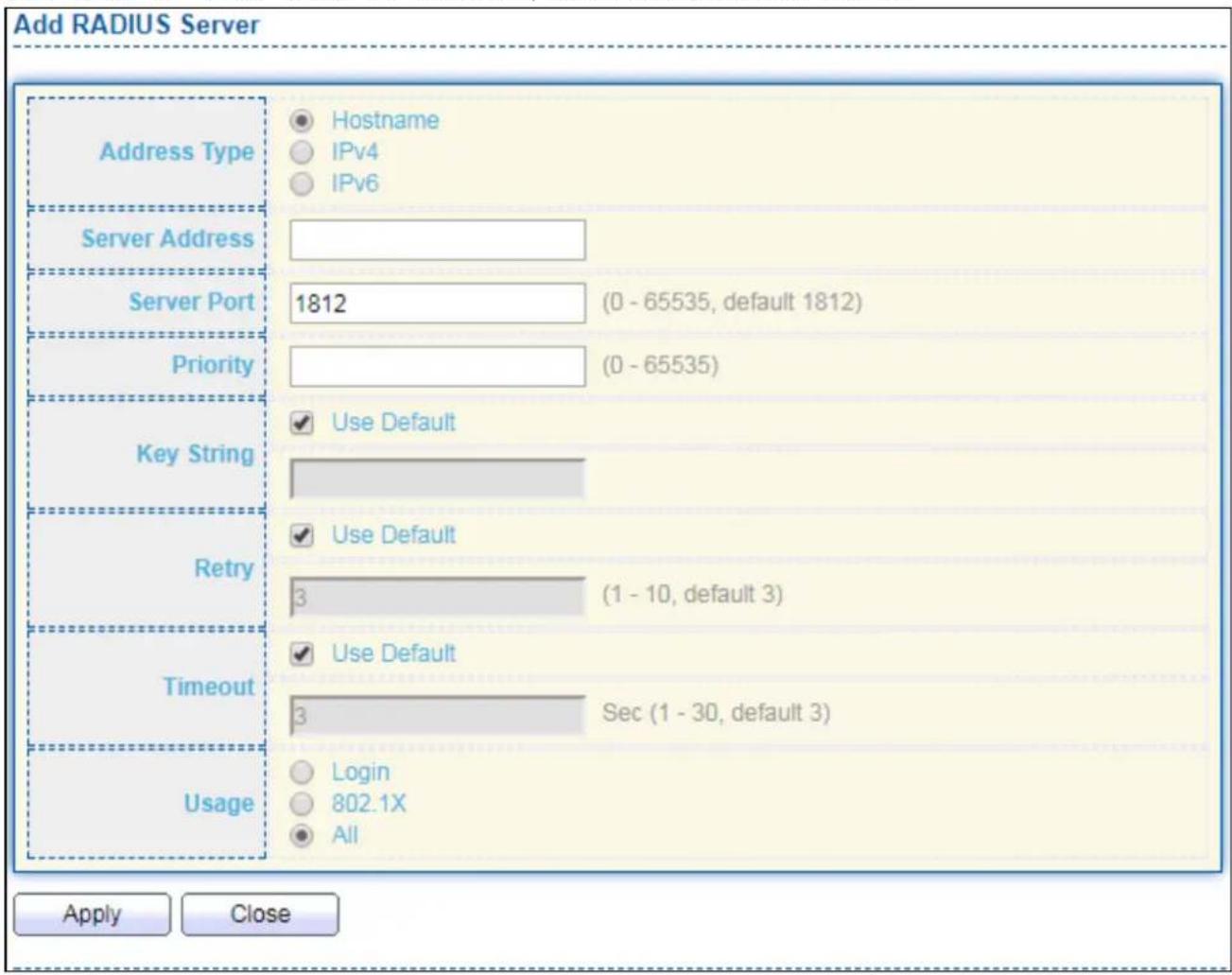
text_image
Add RADIUS Server Address Type Hostname IPv4 IPv6 Server Address Server Port 1812 (0 - 65535, default 1812) Priority (0 - 65535) Key String Use Default Retry Use Default Timeout Use Default Usage Login 802.1X All Apply Close
text_image
Edit RADIUS Server Server Address undefined Server Port 0 (0 - 65535, default 1812) Priority -1 (0 - 65535) Key String Use Default Retry Use Default 0 (1 - 10, default 3) Timeout Use Default 0 Sec (1 - 30, default 3) Usage Login 802.1X All Apply CloseFigure 99 - Security > RADIUS > Add/Edit RADIUS Server
| Item | Descripon |
| Address Type | In add dialog, user need to specify server Address Type● Hostname: Use domain name as server address.● IPv4: Use IPv4 as server address.● IPv6: Use IPv6 as server address. |
| Server Address | In add dialog, user need to input server address based on address type. In edit dialog, it shows current edit server address. |
| Server Port | Set RADIUS server port. |
| Priority | Set RADIUS server priority (smaller value has higher priority).RADIUS session will try to establish with the server seng which has highest priority. If failed, it will try to connect to the server with next higher priority. |
| Retry | Set RADIUS server retry value. If it is fail to connect to server, it will keep trying unl meout with retry mes. |
| Timeout | Set RADIUS server meout value. If it is fail to connect to server, it will keep trying unl meout. |
| Usage | Set RADIUS server usage type● Login: For login authenfaon.● 802.1x: For 802.1x authencaon.● All: For all types. |
IV-10-2 Management Access
Use the Management Access pages to congregate sengs of management access.
IV-10-2-1 Management Service
This page allows user to change management services related conguraons.
To display Management Service click Security > Management Access > Management Service.

text_image
Management Service Telnet Enable SSH Enable HTTP Enable HTTPS Enable SNMP Enable Session Timeout Console 10 Min (0 - 65535, default 10) Telnet 10 Min (0 - 65535, default 10) SSH 10 Min (0 - 65535, default 10) HTTP 10 Min (0 - 65535, default 10) HTTPS 10 Min (0 - 65535, default 10) Password Retry Count Console 3 (0 - 120, default 3) Telnet 3 (0 - 120, default 3) SSH 3 (0 - 120, default 3) Silent Time Console 0 Sec (0 - 65535, default 0) Telnet 0 Sec (0 - 65535, default 0) SSH 0 Sec (0 - 65535, default 0) ApplyFigure 100 - Security > Management Access > Management Service
| Item | Descripon |
| Management Service | Management service admin state.Telnet: Connect CLI through telnet.SSH: Connect CLI through SSH.HTTP: Connect WEBUI through HTTP.HTTPS: Connect WEBUI through HTTPS.SNMP: Manage switch trough SNMP. |
| Session Timeout | Set session meout minutes for user access to user interface. 0 minutes means never meout. |
| Password Retry Count | Retry count is the number which CLI password input error tolerance count. Aer input error password exceeds this count, the CLI will freeze aer silent me. |
| Silent Time | Aer input error password exceeds password retry count, the CLI will freeze aer silent me. |
IV-10-2-2 Management ACL
This page allows user to add or delete management ACL rule. A rule cannot be deleted if under acve.
To display Management ACL page, click Security > Management Access > Management ACL.
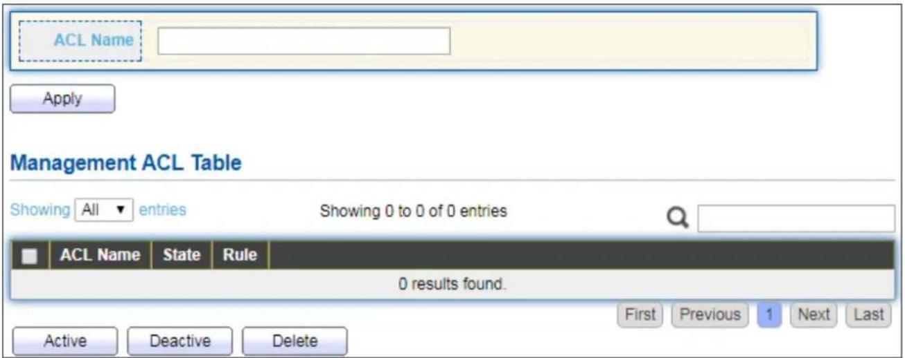
text_image
ACL Name Apply Management ACL Table Showing All entries Showing 0 to 0 of 0 entries ACL Name State Rule 0 results found. Active Deactive Delete First Previous 1 Next LastFigure 101 - Security > Management Access > Management ACL
| Item | Descripon |
| ACL Name | Input MAC ACL name. |
| Management ACL | |
| ACL Name | Display Management ACL name. |
| State | Display Management ACL whether acve. |
| Rule | Display the number Management ACE rule of ACL. |
IV-10-2-3 Management ACE
This page allows user to add, edit or delete ACE rule. An ACE rule cannot be edited or deleted if ACL under acve. New ACE cannot be added if ACL under acve
To display Management ACE page, click Security > Management Access > Management ACE.
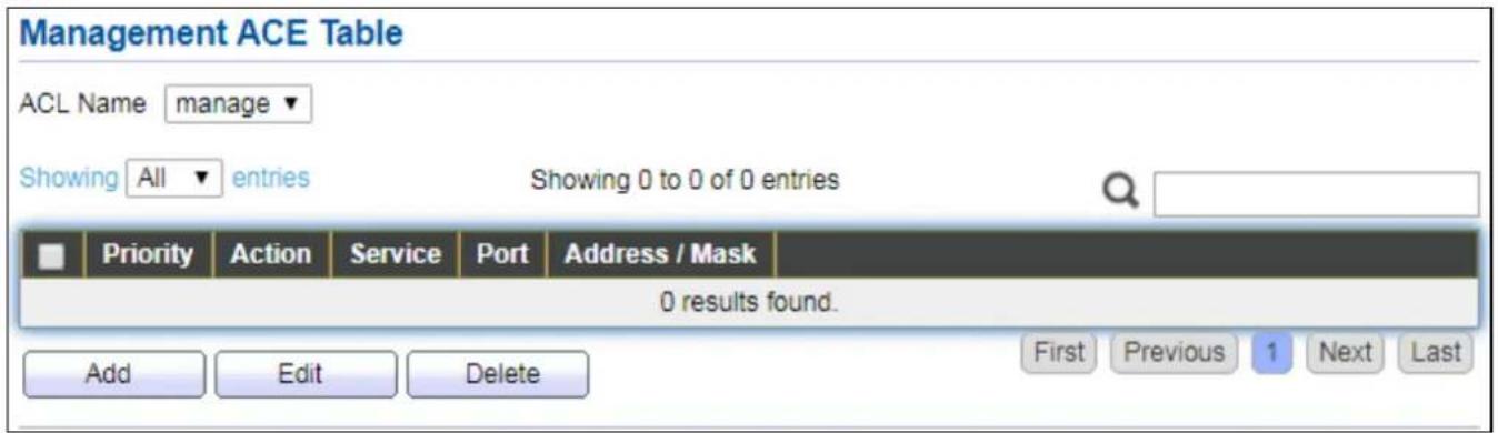
text_image
Management ACE Table ACL Name manage Showing All entries Showing 0 to 0 of 0 entries Priority Action Service Port Address / Mask 0 results found. Add Edit Delete First Previous 1 Next LastFigure 102 - Security > Management Access > Management ACE
| Item | Descripon |
| ACL Name | Select the ACL name to which an ACE is being added. |
| Priority | Display the priority of ACE. |
| Acon | Display the acon of ACE. |
| Service | Display the service ACE |
| Port | Display the port list of ACE |
| Address / Mask | Display the source IP address and mask of ACE. |
Click "Add" or "Edit" buon to view Add/Edit Management ACE menu.
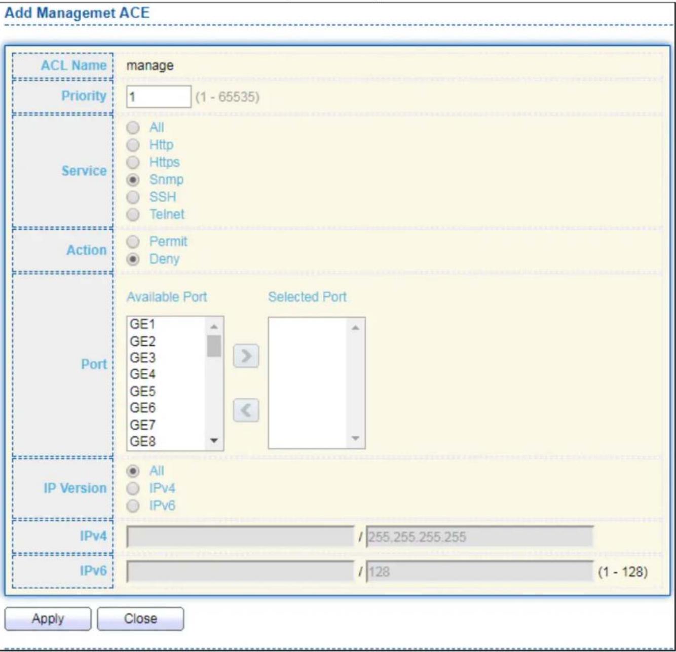
text_image
Add Managemet ACE ACL Name manage Priority 1 (1 - 65535) Service All Http Https Snmp SSH Telnet Action Permit Deny Port Available Port Selected Port GE1 GE2 GE3 GE4 GE5 GE6 GE7 GE8 IP Version All IPv4 IPv6 IPv4 / 255.255.255.255 IPv6 / 128 (1 - 128) Apply Close
text_image
Edit Managemet ACE ACL Name manage Priority 1 Service All Http Https Snmp SSH Telnet Action Permit Deny Port Available Port Selected Port GE2 GE1 GE3 GE4 GE5 GE6 GE7 GE8 GE9 IP Version All IPv4 IPv6 IPv4 / 255.255.255.255 IPv6 / 128 (1 - 128) Apply CloseFigure 103 - Security > Management Access > Add/Edit Management ACE
| Item | Descripon |
| ACL Name | Display the ACL name to which an ACE is being added. |
| Priority | Specify the priority of the ACE. ACEs with higher sequence are processed rst (1 is the highest priority). Only available on Add Dialog. |
| Service | Select the type service of rule.● All: All services.● HTTP: Only HTTP service.● HTTPS: Only HTTPS service● SNMP: Only SNMP service.● SSH: Only SSH service.● Telnet: Only Telnet service |
| Acon | Select the acon aer ACE match packet.● Permit: Forward packets that meet the ACE criteria.● Deny: Drop packets that meet the ACE criteria. |
| Port | Select ports which will be matched. |
| IP Version | Select the type of source IP address.● All: All IP addresses can access.● IPv4: Specify IPv4 address ca access.● IPv6: Specify IPv6 address ca access. |
| IPv4 | Enter the source IPv4 address value and mask to which will be matched. |
| IPv6 | Enter the source IPv6 address value and mask to which will be matched. |
IV-10-3 Authencaon Manager
IV-10-3-1 Property
This page allows user to edit authencaon global sengs and some port mods' conguraons.
To display authencaon manager Property web page, click Security > Authencaon Manager > Property.

text_image
Authentication Type Guest VLAN MAC-Based User ID Format 802.1x MAC-Based WEB-Based Enable XXXXXXXXX Apply Port Mode Table Q Entry Port Authentication Type Host Mode Order Method Guest VLAN VLAN Assign Mode 802.1x MAC-Based WEB-Based 1 GE1 Disabled Disabled Disabled Multiple Authentication 802.1x RADIUS Disabled Static 2 GE2 Disabled Disabled Disabled Multiple Authentication 802.1x RADIUS Disabled Static 3 GE3 Disabled Disabled Disabled Multiple Authentication 802.1x RADIUS Disabled Static 4 GE4 Disabled Disabled Disabled Multiple Authentication 802.1x RADIUS Disabled Static 5 GE5 Disabled Disabled Disabled Multiple Authentication 802.1x RADIUS Disabled Static 6 GE6 Disabled Disabled Disabled Multiple Authentication 802.1x RADIUS Disabled Static 7 GE7 Disabled Disabled Disabled Multiple Authentication 802.1x RADIUS Disabled Static 8 GE8 Disabled Disabled Disabled Multiple Authentication 802.1x RADIUS Disabled Static 9 GE9 Disabled Disabled Disabled Multiple Authentication 802.1x RADIUS Disabled Static 10 GE10 Disabled Disabled Disabled Multiple Authentication 802.1x RADIUS Disabled Static 11 GE11 Disabled Disabled Disabled Multiple Authentication 802.1x RADIUS Disabled Static 12 GE12 Disabled Disabled Disabled Multiple Authentication 802.1x RADIUS Disabled Static 13 GE13 Disabled Disabled Disabled Multiple Authentication 802.1x RADIUS Disabled Static 14 GE14 Disabled Disabled Disabled Multiple Authentication 802.1x RADIUS Disabled Static 15 GE15 Disabled Disabled Disabled Multiple Authentication 802.1x RADIUS Disabled Static 16 GE16 Disabled Disabled Disabled Multiple Authentication 802.1x RADIUS Disabled Static 17 GE17 Disabled Disabled Disabled Multiple Authentication 802.1x RADIUS Disabled Static 18 GE18 Disabled Disabled Disabled Multiple Authentication 802.1x RADIUS Disabled Static 19 GE19 Disabled Disabled Disabled Multiple Authentication 802.1x RADIUS Disabled StaticFigure 104 - Security > Authencaon Manager > Property
| Item | Descripon |
| Authencaon Type | Set checkbox to enable/disable following authencaon types● 802.1x: Use IEEE 802.1x to do authencaon● MAC-Based: Use MAC address to do authencaon● WEB-Based: Prompt authencaon web page for user to doauthencaon |
| Guest VLAN | Set checkbox to enable/disable guest VLAN, if guest VLAN is enabled,you need to select one available VLAN ID to be guest VID. |
| MAC-Based UserID Format | Select mac-based authencaon RADIUS username/password ID format.●XXXXXXXXXXXX●XXXXXXXXXXXX●XX:XX:XX:XX:XX:XX●xx:xx:xx:xx:xx:xx●XX-XX-XX-XX-XX-XX●xx-xx-xx-xx-xx-xx●XX.XX.XX.XX.XX.XX●xx.xx.xx.xx.xx.xx●XXXX:XXXX:XXXX●xxxx:xxxx:xxxx●XXXX-XXXX-XXXX●XXXX-XXXX-XXXX●XXXX.XXXX.XXXX●XXXX.XXXX.XXXX●XXXXX:XXXXXX●XXXXX:XXXXXX●XXXXX-XXXXXX●XXXXX-XXXXXX●XXXXX-XXXXXX |
| Port Mode Table | |
| Port | Port Name. |
| AuthencaonType(802.1X) | 802.1X authencaon type state● Enabled: 802.1X is enabled.● Disabled: 802.1X is disabled. |
| AuthencaonType(MAC-Based) | MAC-Based authencaon type state● Enabled: MAC-Based authencaon is enabled● Disabled: MAC-Based authencaon is disabled |
| AuthencaonType(WEB-Based) | WEB-Based authencaon type state● Enabled: WEB-Based authencaon is enabled● Disabled: WEB-Based authencaon is disabled |
| Host Mode | Authencang host mode● Mulple Authencaon: In this mode, every client need to pass authencate procedure individually.● Mulple Hosts: In this mode, only one client need to be authenticated and other clients will get the same access accessibility. Web-auth cannot be enabled in this mode.● Single Host: In this mode, only one host is allowed to be authenticated. It is the same as Mul-auth mode with max hosts number congure to be 1. |
| Order | Support following authencaon type order combinaons. Web Authencaon should always be the last type. The authencaon manager will go to next type if current type is not enabled or authenticated fail.802.1xMAC-BasedWEB-Based802.1x MAC-Based802.1x WEB-BasedMAC-Based 802.1xWEB-Based 802.1x802.1x MAC-Based WEB-Based802.1x WEB-Based MAC-Based |
| Method | Support following authencaon method order combinaons. These orders only available on MAC-Based authencaon and WEB-Based authencaon. 802.1x only support Radius method.Local: Use DUT's local database to do authencaonRadius: Use remote RADIUS server to do authencaonLocal RadiusRadius Local |
| Guest VLAN | Port guest VLAN enable stateEnabled: Guest VLAN is enabled on port.Disabled: Guest VLAN is disabled on port. |
| VLAN Assign Mode | Support following VLAN assign mode and only apply when source is RADIUSDisable: Ignore the VLAN authorizaon result and keep original VLAN of host.Reject: If get VLAN authorized informaon, just use it. However, if there is no VLAN authorized informaon, reject the host and make it unauthorized.Stac: If get VLAN authorized informaon, just use it. If there is no VLAN authorized informaon, keep original VLAN of host. |
Click "Edit" buon to view the Edit Port Mode menu.
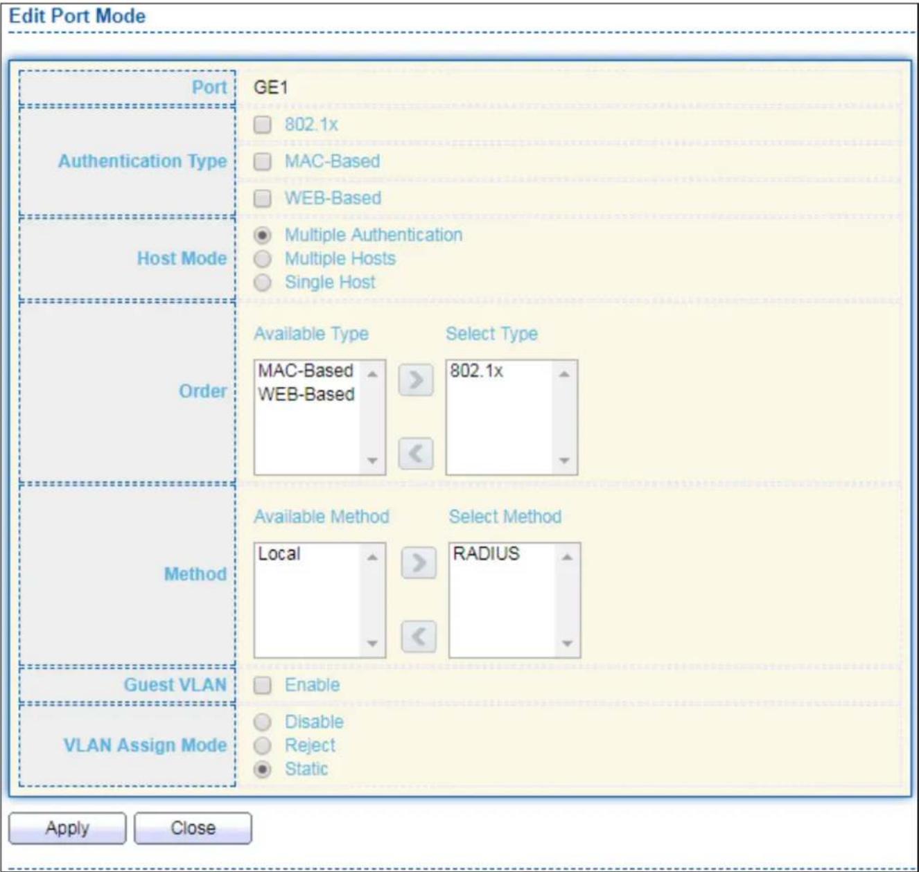
text_image
Edit Port Mode Port Authentication Type Host Mode Order Method Guest VLAN VLAN Assign Mode GE1 802.1x MAC-Based WEB-Based Multiple Authentication Multiple Hosts Single Host Available Type Select Type MAC-Based 802.1x WEB-Based Available Method Select Method Local RADIUS Enable Disable Reject Static Apply CloseFigure 105 - Security > Authencaon Manager > Property > Edit Port Mode
| Item | Descripon |
| Port | Selected port list. |
| Authencaon Type | Set checkbox to enable/disable authencaon types. |
| Host Mode | Select authencang host modeMulple Authencaon: In this mode, every client need to pass authenticate procedure individually.Mulple Hosts: In this mode, only one client need to be authenticated and other clients will get the same access accessibility. Web-auth cannot be enabled in this mode.Single Host: In this mode, only one host is allowed to be authenticated. It is the same as Mul-auth mode with max hosts number congure to be 1. |
| Order | Support following authencaon type order combinaons. Web Authencaon should always be the last type. The authencaon manager will go to next type if current type is not enabled or authenticated fail.802.1xMAC-BasedWEB-Based802.1x MAC-Based802.1x WEB-BasedMAC-Based 802.1xWEB-Based 802.1x802.1x MAC-Based WEB-Based802.1x WEB-Based MAC-Based |
| Method | Support following authencaon method order combinaons. These orders only available on MAC-Based authencaon and WEB-Based authencaon. 802.1x only support Radius method.Local: Use DUT's local database to do authencaon.Radius: Use remote RADIUS server to do authencaon.Local Radius.Radius Local. |
| Guest VLAN | Set checkbox to enable/disable guest VLAN. |
| VLAN Assign Mode | Support following VLAN assign mode and only apply when source is RADIUSDisable: Ignore the VLAN authorizaon result and keep original VLAN of host.Reject: If get VLAN authorized informaon, just use it. However, if there is no VLAN authorized informaon, reject the host and make it unauthorized.Stac: If get VLAN authorized informaon, just use it. If there is no VLAN authorized informaon, keep original VLAN of host. |
IV-10-3-2 Port Seng
This page allows user to congregate authencaon manger port sengs
To display the authencaon manager Port Seng web page, click Security > Authencaon Manager > Port Seng.
| Port Setting Table | |||||||||||||
| Q | |||||||||||||
| Entry | Port | Port Control | Reauthentication | Max Hosts | Common Timer | 802.1x Parameters | Web Based Parameters Max Login | ||||||
| Reauthentication | Inactive | Quiet | TX Period | Supplicant Timeout | Server Timeout | Max Request | |||||||
| 1 | GE1 | Disabled | Disabled | 256 | 3600 | 60 | 60 | 30 | 30 | 30 | 2 | 3 | |
| 2 | GE2 | Disabled | Disabled | 256 | 3600 | 60 | 60 | 30 | 30 | 30 | 2 | 3 | |
| 3 | GE3 | Disabled | Disabled | 256 | 3600 | 60 | 60 | 30 | 30 | 30 | 2 | 3 | |
| 4 | GE4 | Disabled | Disabled | 256 | 3600 | 60 | 60 | 30 | 30 | 30 | 2 | 3 | |
| 5 | GE5 | Disabled | Disabled | 256 | 3600 | 60 | 60 | 30 | 30 | 30 | 2 | 3 | |
| 6 | GE6 | Disabled | Disabled | 256 | 3600 | 60 | 60 | 30 | 30 | 30 | 2 | 3 | |
| 7 | GE7 | Disabled | Disabled | 256 | 3600 | 60 | 60 | 30 | 30 | 30 | 2 | 3 | |
| 8 | GE9 | Disabled | Disabled | 256 | 3600 | 60 | 60 | 30 | 30 | 30 | 2 | 3 | |
| 9 | GE9 | Disabled | Disabled | 256 | 3600 | 60 | 60 | 30 | 30 | 30 | 2 | 3 | |
| 10 | GE10 | Disabled | Disabled | 256 | 3600 | 60 | 60 | 30 | 30 | 30 | 2 | 3 | |
| 11 | GE11 | Disabled | Disabled | 256 | 3600 | 60 | 60 | 30 | 30 | 30 | 2 | 3 | |
| 12 | GE12 | Disabled | Disabled | 256 | 3600 | 60 | 60 | 30 | 30 | 30 | 2 | 3 | |
| 13 | GE13 | Disabled | Disabled | 256 | 3600 | 60 | 60 | 30 | 30 | 30 | 2 | 3 | |
| 14 | GE14 | Disabled | Disabled | 256 | 3600 | 60 | 60 | 30 | 30 | 30 | 2 | 3 | |
| 15 | GE15 | Disabled | Disabled | 256 | 3600 | 60 | 60 | 30 | 30 | 30 | 2 | 3 | |
| 16 | GE16.5.5.5.5.5.5.5.5.5.5.5.5.5.5.5.5.5.5.5.5.5.5.5.5.5.5.5.5.5.5.5.5.5.5.5.5.5.5.5.5.5.5.5.5.5.5.5.5.5. 5.5.5.5.5.5.5.5.5.5.5.5.5.5.5.5.5.5.5.5.5.5.5.5. 5. 5. 5. 5. 5. 5. 5. 5. 5. 5. 5. 5. 5. 5. 5. 5. 5, 5, 5, 5, 5, 5, 5, 5, 5, 5, 5, 5, 5, 5, 5, 5, 5, 5, 5, 5, 5, 5, 5, 5, 5, 5, 5, 5, 5, 5, 5, 5, 17, 17, 17, 17, 17, 17, 17, 17, 17, 17, 17, 17, 17, 17, 17, 17, 17, 17, 17, 17, 17, 17, 17, 17, 17, 18, 18, 18, 18, 18, 18, 18, 18, 18, 18, 18, 18, 18, 18, 18, 18, 18, 18, 18, 18, 18, 18, 18, 18, 18, 19 , GE19 , GE20 , GE21 , GE22 , GE23 , GE24 , GE24 , GE24 , GE24 , GE24 , GE24 , GE24 , GE24 , GE24 , GE24 , GE24 , GE24 , GE24 , GE24 , GE24 , GE24 , GE24 , GE24 , GE24 , GE24 , GE24 , GE24 , GE24 , GE24 , GE24 , GE28 , GE28 , GE28 , GE28 , GE28 , GE28 , GE28 , GE28 , GE28 , GE28 , GE28 , GE28 , GE28 , GE28 , GE28 , GE28 , GE28 , GE28 , GE28 , GE28 , GE28 , GE28 , GE28 , GE28 , GE28 , GE29 , GE29 , GE29 , GE29 , GE29 , GE29 , GE29 , GE29 , GE29 , GE29 , GE29 , GE29 , GE29 , GE29 , GE29 , GE29 , GE29 , GE29 , GE29 , GE29 , GE29 , GE29 , GE29 , GE29 , GE29 , GE28 | Edit | ||||||||||||
Figure 106 - Security > Authencaon Manager > Port Seng
| Item | Descripon |
| Port | Port |
| Port Control | Support following authencaon port control types.● Disable: Disable authencaon funcon and all clients have network accessibility.● Force Authorized: Port is force authorized and all clients have network accessibility.● Force Unauthorized: Port is force unauthorized and all clients have no network accessibility.● Auto: Need passing authencaon procedure to get network accessibility. |
| Reauthencaon | Reauthecate state● Enabled: Host will be reauthenticated aer reauthencaon period.● Disabled: Host will not be reauthenticated aer reauthencaon period. |
| Max Hosts | In Mulple Authencaon mode, total host number cannot not exceed max hosts number. |
| Common Timer (Reauthencaon) | Aer re-authencate period, host will return to initial state and need to pass authencaon procedure again. |
| Common Timer (Inacve) | If no packet from the authenticated host, the inacve mer will increase. Aer inacve meout, the host will be unauthorized and corresponding session will be deleted. In mul-host mode, the packet is counting on the authorized host only. |
| Common Timer (Quiet) | When port is in Locked state aer authencang fail several mes, the host will be locked in quiet period. Aer this quiet period, the host is allowed to authenticate again. |
| 802.1X Params (TX Period) | Number of seconds that the device waits for a response to an Extensible Authencaon Protocol (EAP) request/identity frame from the supplicant (client) before resending the request. |
| 802.1X Params (Supplicant Timeout) | The maximum number of EAP requests that can be sent. If a response is not received aer the denied period (supplicant meout), the authencaon process is restarted. |
| 802.1X Params (Server Timeout) | Number of seconds that lapses before EAP requests are resent to the supplicant. |
| 802.1X Params (Max Request) | Number of seconds that lapses before the device resends a request to the authencaon server. |
| Web-Based Param (Max Login) | Allow user login fail number. Aer login fail number exceed, the host will enter Lock state and is not able to authenticate unl quiet period exceed. |
Click "Edit" buon to view Edit Port Seng menu.

text_image
Edit Port Setting Port GE1 Port Control Disabled Force Authorized Force Unauthorized Auto Reauthentication Enable Max Hosts 256 (1 - 256, default 256) Common Timer Reauthentication 3600 Sec (300 - 4294967294, default 3600) Inactive 60 Sec (60 - 65535, default 60) Quiet 60 Sec (0 - 65535, default 60) 802.1x Parameters TX Period 30 Sec (1 - 65535, default 30) Supplicant Timeout 30 Sec (1 - 65535, default 30) Server Timeout 30 Sec (1 - 65535, default 30) Max Request 2 (1 - 10, default 2) Web-Based Parameters Max Login Infinite 3 (3 - 10, default 3) Apply CloseFigure 107 - Security > Authencaon Manager > Port Seng > Edit Port Seng
| Item | Descripon |
| Port | Port Name. |
| Port Control | Support following authencaon port control types.● Disable: Disable authencaon funcon and all clients have network accessibility. Force Authorized: Port is force authorized and all clients have network accessibility.● Force Unauthorized: Port is force unauthorized and all clients have no network accessibility.● Auto: Need passing authencaon procedure to get network accessibility. |
| Reauthencaon | Set checkbox to enable/disable reuauthencaon. |
| Max Hosts | In Mulple Authencaon mode, total host number cannot not exceed max hosts number. |
| Common Timer | |
| Reauthencaon | Aer re-authencate period, host will return to initial state and need to pass authencaon procedure again. |
| Inacve | If no packet from the authenticated host, the inacve mer will increase. Aer inacve meout, the host will be unauthorized and corresponding session will be deleted. In mul-host mode, the packet is counting on the authorized host only and not all packets on the port. |
| Quiet | When port is in Locked state aer authencang fail several mes, the host will be locked in quiet period. Aer this quiet period, the host is allowed to authenticate again. |
| 802.1X Params | |
| TX Period | Number of seconds that the device waits for a response to an Extensible Authencaon Protocol (EAP) request/identity frame from the supplicant (client) before resending the request. |
| Supplicant Timeout | The maximum number of EAP requests that can be sent. If a response is not received aer the denied period (supplicant meout), the authencaon process is restarted. |
| Server Timeout | Number of seconds that lapses before EAP requests are resent to the supplicant. |
| Max Request | Number of seconds that lapses before the device resends a request to the authencaon server. |
| Web-Based Param | |
| Max Login | Set checkbox to set max login number to be innate or specify max login number. |
IV-10-3-3 Sessions
This page shows all detail informaon of authencaon sessions and allow user to select specific session to delete by clicking "Clear" buon.
To display Sessions web page, click Security > Authencaon Manger > Sessions.

text_image
Sessions Table Showing All entries Showing 0 to 0 cf 0 entries Session ID Port MAC Address Current Type Status Operational Information Authorized Information VLAN Session Time Inactivated Time Quiet Time VLAN Reauthentication Period Inactive Timeout 0 results found. Clear Refresh First Previous 1 Next LastFigure 108 - Security > Authencaon Manager > Sessions
| Item | Descripon |
| Session ID | Session ID is unique of each session. |
| Port | Port name which the host located. |
| MAC Address | Host MAC address. |
| Current Type | Show current authencang type802.1x: Use IEEE 802.1X to do authencangMAC-Based: Use MAC-Based authencaon to do authencang.WEB-Based: Use WEB-Based authencaon to do authencang. |
| Status | Show host authencaon session statusIP version (IPv4, IPv6)Disable: This session is ready to be deletedRunning: Authencaon process is runningAuthorized: Authencaon is passed and geng network accessibility.UnAuthorized: Authencaon is not passed and not geng network accessibility.Locked: Host is locked and do not allow to do authencang unl quiet period.Guest: Host is in the guest VLAN. |
| Operational (VLAN) | Shows host operational VLAN ID. |
| Operational (Session Time) | In “Authorized” state, it shows total me aer authorized. |
| Operational (Inacved) | In “Authorized” state, it shows how long the host do not send any packet. |
| Operational (Quiet Time) | In “Locked” state, it shows total me aer locked. |
| Authorized (VLAN) | Shows VLAN ID given from authorized procedure. |
| Authorized (Reauthencaon Period) | Shows reauthencaon period given from authorized procedure. |
| Authorized (Inacve Timeouts) | Shows inacve meout given from authorized procedure. |
IV-10-4 Port Security
This page allows user to congregate port security sengs for each interface. When port security is enabled on interface, acon will be perform once learned MAC address over limitaon.
To display Port Security web page, click Security > Port Security.
| Entry | Port | State | MAC Address | Action | |
| 1 | GE1 | Disabled | 1 | Discard | |
| 2 | GE2 | Disabled | 1 | Discard | |
| 3 | GE3 | Disabled | 1 | Discard | |
| 4 | GE4 | Disabled | 1 | Discard | |
| 5 | GE5 | Disabled | 1 | Discard | |
| 6 | GE6 | Disabled | 1 | Discard | |
| 7 | GE7 | Disabled | 1 | Discard | |
| 8 | GE8 | Disabled | 1 | Discard | |
| 9 | GE9 | Disabled | 1 | Discard | |
| 10 | GE10 | Disabled | 1 | Discard | |
| 11 | GE11 | Disabled | 1 | Discard | |
| 12 | GE12 | Disabled | 1 | Discard | |
| 13 | GE13 | Disabled | 1 | Discard | |
| 14 | GE14 | Disabled | 1 | Discard | |
| 15 | GE15 | Disabled | 1 | Discard | |
| 16 | GE16 | Disabled | 1 | Discard | |
| 17 | GE17 | Disabled | 1 | Discard | |
| 18 | GE18 | Disabled | 1 | Discard | |
| 19 | GE19 | Disabled | 1 | Discard | |
| 20 | GE20 | Disabled | 1 | Discard | |
| 21 | GE21 | Disabled | 1 | Discard | |
| 22 | GE22 | Disabled | 1 | Discard | |
| 23 | GE23 | Disabled | 1 | Discard | |
| 24 | GE24 | Disabled | 1 | Discard | |
| 25 | GE25 | Disabled | 1 | Discard |
Figure 109 - Security > Port Security
| Item | Descripon |
| State | Enable/Disable the port security funcon. |
| Port | Select one or mulple ports to conjure. |
| State | Select the status of port security● Disable: Disable port security funcon.● Enable: Enable port security funcon. |
| MAC Address | Specify the number of how many mac addresses can be learned. |
| Acon | Select the acon if learned mac addresses● Forward: Forward this packet whose SMAC is new to system and exceed the learning-limit number.● Discard: Discard this packet whose SMAC is new to system and exceed the learning-limit number.● Shutdown: Shutdown this port when receives a packet whose SMAC is new to system and exceed the learning limit number. |
Click "Edit" buon to view Edit Port Security menu.

text_image
Edit Port Security Port GE1 State Enable MAC Address 1 (0 - 255, default 1) Action Forward Discard Shutdown Apply CloseFigure 110 - Security > Port Security > Edd Port Security
| Item | Descripon |
| Port | Select one or mulple ports to congure. |
| State | Select the status of port securityDisable: Disable port security funcon.Enable: Enable port security funcon. |
| MAC Address | Specify the number of how many mac addresses can be learned. |
| Acon | Select the acon if learned mac addressesForward: Forward this packet whose SMAC is new to system and exceed the learning-limit number.Discard: Discard this packet whose SMAC is new to system and exceed the learning-limit number.Shutdown: Shutdown this port when receives a packet whose SMAC is new to system and exceed the learning limit number. |
IV-10-5 Protected Port
This page allows user to conjure protected port seng to prevent the selected ports from communicaon with each other. Protected port is only allowed to communicate with unprotected port. In other words, protected port is not allowed to communicate with another protected port.
To display Protected Port web page, click Security > Protected Port.
Protected Port Table
| Entry | Port | State |
| 1 | GE1 | Unprotected |
| 2 | GE2 | Unprotected |
| 3 | GE3 | Unprotected |
| 4 | GE4 | Unprotected |
| 5 | GE5 | Unprotected |
| 6 | GE6 | Unprotected |
| 7 | GE7 | Unprotected |
| 8 | GE8 | Unprotected |
| 9 | GE9 | Unprotected |
| 10 | GE10 | Unprotected |
| 11 | GE11 | Unprotected |
| 12 | GE12 | Unprotected |
| 13 | GE13 | Unprotected |
| 14 | GE14 | Unprotected |
| 15 | GE15 | Unprotected |
| 16 | GE16 | Unprotected |
| 17 | GE17 | Unprotected |
| 18 | GE18 | Unprotected |
| 19 | GE19 | Unprotected |
| 20 | GE20 | Unprotected |
| 21 | GE21 | Unprotected |
| 22 | GE22 | Unprotected |
| 23 | GE23 | Unprotected |
| 24 | GE24 | Unprotected |
| 25 | GE25 | Unprotected |
| 26 | GE26 | Unprotected |
| 27 | GE27 | Unprotected |
| 28 | GE28 | Unprotected |
Figure 111 - Security > Protected Port
| Item | Descripon |
| Port | Port Name. |
| State | Port protected admin state.● Protected: Port is protected.● Unprotected: Port is unprotected |
Click "Edit" buon to view Edit Protected Port menu.
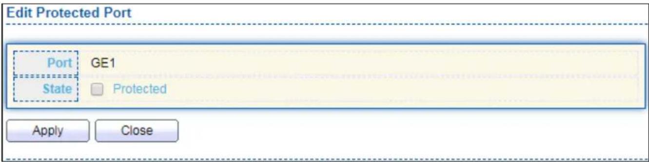
text_image
Edit Protected Port Port GE1 State □ Protected Apply CloseFigure 112 - Security > Protected Port > Edit Protected Port
| Item | Descripon |
| Port | Selected port list. |
| State | Port protected admin state.● Protected: Enable protecng funcon.● Unprotected: Disable protecng funcon. |
IV-10-6 Storm Control
To display Storm Control global seng web page, click Security > Storm Control.
| Entry | Port | State | Broadcast | Unknown Multicast | Unknown Unicast | Action | |||
| State | Rate (Kbps) | State | Rate (Kbps) | State | Rate (Kbps) | ||||
| 1 | GE1 | Disabled | Disabled | 10000 | Disabled | 10000 | Disabled | 10000 | Drop |
| 2 | GE2 | Disabled | Disabled | 10000 | Disabled | 10000 | Disabled | 10000 | Drop |
| 3 | GE3 | Disabled | Disabled | 10000 | Disabled | 10000 | Disabled | 10000 | Drop |
| 4 | GE4 | Disabled | Disabled | 10000 | Disabled | 10000 | Disabled | 10000 | Drop |
| 5 | GE5 | Disabled | Disabled | 10000 | Disabled | 10000 | Disabled | 10000 | Drop |
| 6 | GE6 | Disabled | Disabled | 10000 | Disabled | 10000 | Disabled | 10000 | Drop |
| 7 | GE7 | Disabled | Disabled | 10000 | Disabled | 10000 | Disabled | 10000 | Drop |
| 8 | GE8 | Disabled | Disabled | 10000 | Disabled | 10000 | Disabled | 10000 | Drop |
| 9 | GE9 | Disabled | Disabled | 10000 | Disabled | 10000 | Disabled | 10000 | Drop |
| 10 | GE10 | Disabled | Disabled | 10000 | Disabled | 10000 | Disabled | 10000 | Drop |
| 11 | GE11 | Disabled | Disabled | 10000 | Disabled | 10000 | Disabled | 10000 | Drop |
| 12 | GE12 | Disabled | Disabled | 10000 | Disabled | 10000 | Disabled | 10000 | Drop |
| 13 | GE13 | Disabled | Disabled | 10000 | Disabled | 10000 | Disabled | 10000 | Drop |
| 14 | GE14 | Disabled | Disabled | 10000 | Disabled | 10000 | Disabled | 10000 | Drop |
| 15 | GE15 | Disabled | Disabled | 10000 | Disabled | 10000 | Disabled | 10000 | Drop |
| 16 | GE16 | Disabled | Disabled | 10000 | Disabled | 10000 | Disabled | 10000 | Drop |
| 17 | GE17 | Disabled | Disabled | 10000 | Disabled | 10000 | Disabled | 10000 | Drop |
| 18 | GE18 | Disabled | Disabled | 10000 | Disabled | 10000 | Disabled | 10000 | Drop |
| 19. 2 2 2 2 2 2 2 2 2 2 2 2 2 2 2 2 2 2 2 2 2 2 2 2 2 2 2 2 2 2 2 2 2 2 2 2 2 2 2 2 2 2 2 2 2 2 2 2 2 2 3 3 3 3 3 3 3 3 3 3 3 3 3 3 3 3 3 3 3 3 3 3 3 3 3 3 3 3 3 3 3 3 3 3 3 3 3 3 3 3 3 3 3 3 3 3.4.4.4.4.4.4.4.4.4.4.4.4.4.4.4.4.4.4.4.4.4.4.4.4.4.4.4.4.4.4.4.4.4.4.4.4.4.4.4.4.4.4.4.4.4.4.4.4.4.4.5 .5 .5 .5 .5 .5 .5 .5 .5 .5 .5 .5 .5 .5 .5 .5 .5 .5 .5 .5 .5 .5 .5 .5 .5 .5 .5 .5 .5 .5 .5 .5 .5 .5 .5 .5 .5 .5 .5 .5 .5 .5 .5 .5 .5 .5 .5 .5 .5 .5 .5 ,6 ,7 ,8 ,9 ,1,1,2,3,4,5,6,7,8,9,1,2,3,4,5,6,7,8,9,1,2,3,4,5,6,7,8,9,1,2,3,4,5,6,7,8,9,1,2,3,4,5,6,7,8,9,1,2,3,4,5,6,7,8,9,1,2,3,4,6,7,8,9,1,2,3,4,6,7,8,9,1,2,3,4,6,7,8,9 ,8 ,9 ,12 ,13 ,14 ,15 ,16 ,17 ,18 ,19 ,2 2 ,2 ,2 ,2 ,2 ,2 ,2 ,2 ,2 ,2 ,2 ,2 ,2 ,2 ,2 ,2 ,2 ,2 ,2 ,2 ,2 ,2 ,2 ,2 ,2 ,2 ,2 ,2 ,2 ,2 ,2 ,2 ,2 ,2 ,2 ,2 ,2 ,2 ,2 ,2 ,2 ,2 ,2 ,2 ,2 ,2 ,2 ,2 ,2 ,2 ,2 | |||||||||
Figure 113 - Security > Storm Control
| Item | Descripon |
| Mode(Unit) | Select the unit of storm controlPacket / Sec: storm control rate calculates by packet-basedKbits / Sec: storm control rate calculates by octet-based. |
| IFG | Select the rate calculates w/o preamble & IFG (20 bytes)Excluded: exclude preamble & IFG (20 bytes) when count ingress storm control rate.● Included: include preamble & IFG (20 bytes) when count ingress storm control rate. |
Click "Edit" buon to view Edit Port Seng menu.

text_image
Edit Port Setting Port GE1 State Enable Broadcast Enable Unknown Multicast Enable Unknown Unicast Enable Action Drop Shutdown Apply CloseFigure 114 - Security > Storm Control > Edit Port Seng
| Item | Descripon |
| Port | Select the seng ports. |
| State | Select the state of sengEnable: Enable the storm control funcon. |
| Broadcast | Enable: Enable the storm control funcon of Broadcast packet. Value of storm control rate, Unit: pps (packet per-second, range 1-262143) or Kbps (Kbits per-second, range16 - 1000000) depends on global mode seng. |
| UnknownMulcast | Enable: Enable the storm control funcon of Unknown mulcast packet. Value of storm control rate, Unit: pps (packet per-second, range 1-262143) or Kbps (Kbits per-second, range16 - 1000000) depends on global mode seng. |
| Unknown Unicast | Enable: Enable the storm control funcon of Unknown unicast packet. Value of storm control rate, Unit: pps (packet per-second, range 1 - 262143) or Kbps (Kbits per-second, range16 - 1000000) depends on global mode seng. |
| Acon | Select the state of sengDrop: Packets exceed storm control rate will be dropped.Shutdown: Port will be shutdown when packets exceed storm control rate. |
IV-10-7 DoS
A Denial of Service (DoS) aack is a hacker aempt to make a device unavailable to its users. DoS aacks saturate the device with external communicaon requests, so that it cannot respond to legitimate trac. These aacks usually lead to a device CPU overload.
The DoS protecon feature is a set of predened rules that protect the network from malicious aacks. The DoS Security Suite Sengs enables acvang the security suite.
IV-10-7-1 Property
To display Dos Global Seng web page, click Security > Dos > Property.

text_image
POD Land UDP Blat TCP Blat Enable Enable Enable Enable DMAC = SMAC Null Scan Attack X-Mas Scan Attack TCP SYN-FIN Attack Enable Enable Enable Enable TCP SYN-RST Attack ICMP Fragment TCP-SYN Note: Source Port < 1024 TCP Fragment Enable Note: Offset = 1 Ping Max Size Enable IPv4 Enable IPv6 512 Byte (0 - 65535, default 512) TCP Min Hdr size Enable 20 Byte (0 - 31, default 20) IPv6 Min Fragment Enable 1240 Byte (0 - 65535, default 1240) Smurf Attack Enable 0 Netmask Length (0 - 32, default 0) ApplyFigure 115 - Security > DoS > Property
| Item | Descripon |
| POD | Avoids ping of death aack. |
| Land | Drops the packets if the source IP address is equal to the desnaon IP address. |
| UDP Blat | Drops the packets if the UDP source port equals to the UDPdesnaon port. |
| TCP Blat | Drops the packages if the TCP source port is equal to the TCP desnaon port. |
| DMAC = SMAC | Drops the packets if the desnaon MAC address is equal to the source MAC address. |
| Null Scan Aach | Drops the packets with NULL scan. |
| X-Mas Scan Aack | Drops the packets if the sequence number is zero, and the FIN, URG and PSH bits are set. |
| TCP SYN-FIN Aack | Drops the packets with SYN and FIN bits set. |
| TCP SYN-RST Aack | Drops the packets with SYN and RST bits set |
| ICMP Fragment | Drops the fragmented ICMP packets. |
| TCP SYN (SPORT<1024) | Drops SYN packets with sport less than 1024. |
| TCP Fragment (Oset = 1) | Drops the TCP fragment packets with oset equals to one. |
| Ping Max Size | Specify the maximum size of the ICMPv4/ICMPv6 ping packets. The valid range is from 0 to 65535 bytes, and the default value is 512 bytes. |
| IPv6 Min Fragment | Checks the minimum size of IPv6 fragments, and drops the packets smaller than the minimum size. The valid range is from 0 to 65535 bytes, and default value is 1240 bytes. |
| Smurf Aack | Avoids smurf aack. The length range of the netmask is from 0 to 323 bytes, and default length is 0 bytes. |
IV-10-7-2 Port Seng
To congure and display the state of DoS protecon for interfaces, click Security > DoS > Port Seng.
| Port Setting Table | |||
| Q | |||
| Entry | Port | State | |
| 1 | GE1 | Disabled | |
| 2 | GE2 | Disabled | |
| 3 | GE3 | Disabled | |
| 4 | GE4 | Disabled | |
| 5 | GE5 | Disabled | |
| 6 | GE6 | Disabled | |
| 7 | GE7 | Disabled | |
| 8 | GE8 | Disabled | |
| 9 | GE9 | Disabled | |
| 10 | GE10 | Disabled | |
| 11 | GE11 | Disabled | |
| 12 | GE12 | Disabled | |
| 13 | GE13 | Disabled | |
| 14 | GE14 | Disabled | |
| 15 | GE15 | Disabled | |
| 16 | GE16 | Disabled | |
| 17 | GE17 | Disabled | |
| 18 | GE18 | Disabled | |
| 19 | GE19 | Disabled | |
| 20 | GE20 | Disabled | |
| 21 | GE21 | Disabled | |
| 22 | GE22 | Disabled | |
| 23 | GE23 | Disabled | |
| 24 | GE24 | Disabled | |
| 25 | GE25 | Disabled | |
| 26 | GE26 | Disabled | |
| 27 | GE27 | Disabled | |
| 28 | GE28 | Disabled | |
Figure 116 - Security > DoS > Port Seng
| Item | Descripon |
| Port | Interface or port number. |
| State | Enable/Disable the DoS protecon on the interface. |
IV-10-8 DHCP Snooping
Use the DHCP Snooping pages to conjure sengs of DHCP Snooping.
IV-10-8-1 Property
This page allows user to congregate global and per interface sengs of DHCP Snooping.
To display property page, click Security > DHCP Snooping > Property.
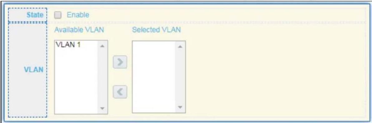
text_image
State Enable VLAN Available VLAN Selected VLAN VLAN 1
Port Setting Table

| Entry | Port | Trust | Verify Chaddr | Rate Limit |
| 1 | GE1 | Disabled | Disabled | Unlimited |
| 2 | GE2 | Disabled | Disabled | Unlimited |
| 3 | GE3 | Disabled | Disabled | Unlimited |
| 4 | GE4 | Disabled | Disabled | Unlimited |
| 5 | GE5 | Disabled | Disabled | Unlimited |
| 6 | GE6 | Disabled | Disabled | Unlimited |
| 7 | GE7 | Disabled | Disabled | Unlimited |
| 8 | GE8 | Disabled | Disabled | Unlimited |
| 9 | GE9 | Disabled | Disabled | Unlimited |
| 10 | GE10 | Disabled | Disabled | Unlimited |
| 11 | GE11 | Disabled | Disabled | Unlimited |
| 12 | GE12 | Disabled | Disabled | Unlimited |
| 13 | GE13 | Disabled | Disabled | Unlimited |
| 14 | GE14 | Disabled | Disabled | Unlimited |
| 15 | GE15 | Disabled | Disabled | Unlimited |
| 16 | GE16 | Disabled | Disabled | Unlimited |
| 17 | GE17 | Disabled | Disabled | Unlimited |
| 18 | GE18 | Disabled | Disabled | Unlimited |
| 19 | GE19 | Disabled | Disabled | Unlimited |
Figure 117 - Security > DHCP Snooping > Property
| Item | Descripon |
| State | Set checkbox to enable/disable DHCP Snooping funcon. |
| VLAN | Select VLANs in le box then move to right to enable DHCP Snooping. Or select VLANs in right box then move to le to disable DHCP Snooping. |
| Port Seng Table | |
| Port | Display port ID. |
| Trust | Display enable/disabled trust aribute of interface. |
| Verify Chaddr | Display enable/disabled chaddr validaon aribute of interface. |
| Rate Limit | Display rate limitaon value of interface. |
Click "Edit" buon to view Edit Port Seng menu.
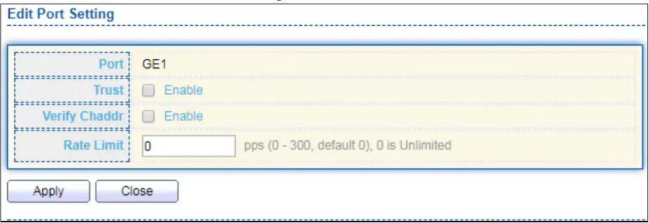
text_image
Edit Port Setting Port GE1 Trust Enable Verify Chaddr Enable Rate Limit 0 pps (0 - 300, default 0), 0 is Unlimited Apply CloseFigure 118 - Security > DHCP Snooping > Property > Edit Port Seng
| Item | Descripon |
| Port | Display selected port to be edited |
| Trust | Set checkbox to enable/disabled trust of interface. All DHCP packet will be forward directly if enable trust. Default is disabled. |
| Verify Chaddr | Set checkbox to enable or disable chaddr validaon of interface. All DHCP packets will be checked whether client hardware mac address is same as source mac in Ethernet header if enable chaddr validaon. Default is disabled. |
| Rate Limit | Input rate limitaon of DHCP packets. The unit is pps. 0 means unlimited. Default is unlimited. |
IV-10-8-2 Stascs
This page allows user to browse all stascs that recorded by DHCP snooping funcon.
To view the Stascs menu, navigate to Security > DHCP Snooping > Stascs.
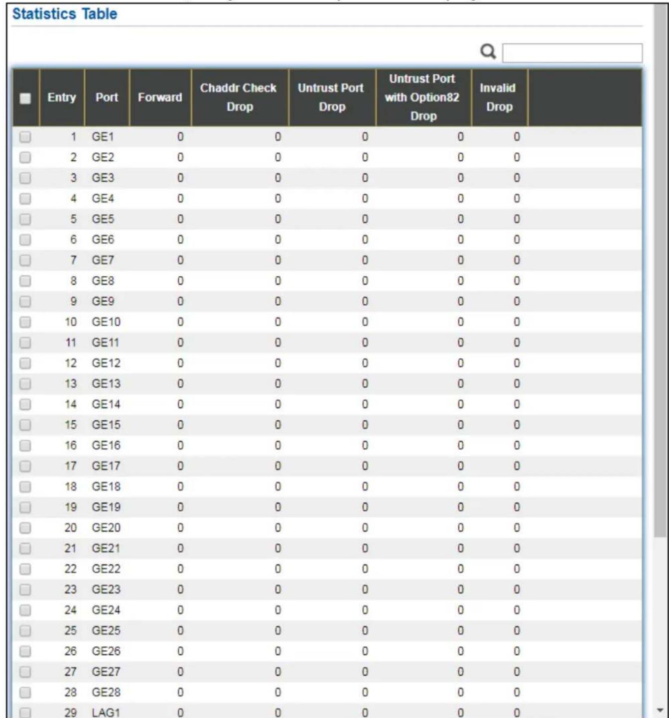
Figure 119 - Security > DHCP Snooping > Stascs
| Item | Descripon |
| Port | Display port ID. |
| Forwarded | Display how many packets forwarded normally. |
| Chaddr Check Drop | Display how many packets dropped by chaddr validaon. |
| Untrusted Port Drop | Display how many DHCP server packets that are received by untrusted port dropped. |
| Untrusted Port with Opon82 Drop | Display how many packets dropped by untrusted port with opon82 checking. |
| Invalid Drop | Display how many packets dropped by invalid checking. |
IV-10-8-3 Opon82 Property
This page allows user to set string of DHCP opon82 remote ID led. The string will each in opon82 if opon inserted.
To display Opon82 Property page, click Security > DHCP Snooping > Opon82 Property.
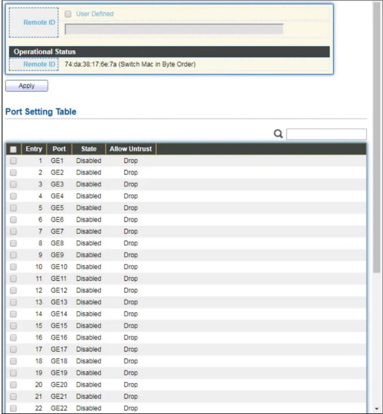
text_image
Remote ID User Defined Operational Status Remote ID 74:da:38:17:6e:7a (Switch Mac in Byte Order) Apply Port Setting Table Entry Port State Allow Untrust 1 GE1 Disabled Drop 2 GE2 Disabled Drop 3 GE3 Disabled Drop 4 GE4 Disabled Drop 5 GE5 Disabled Drop 6 GE6 Disabled Drop 7 GE7 Disabled Drop 8 GE8 Disabled Drop 9 GE9 Disabled Drop 10 GE10 Disabled Drop 11 GE11 Disabled Drop 12 GE12 Disabled Drop 13 GE13 Disabled Drop 14 GE14 Disabled Drop 15 GE15 Disabled Drop 16 GE16 Disabled Drop 17 GE17 Disabled Drop 18 GE18 Disabled Drop 19 GE19 Disabled Drop 20 GE20 Disabled Drop 21 GE21 Disabled Drop 22 GE22 Disabled DropFigure 120 - Security > DHCP Snooping > Opon82 Property
| Item | Descripon |
| User Dened | Set checkbox to enable user-dened remote-ID. By default, remote ID is switch mac in byte order. |
| Remote ID | Input user-dened remote ID. Only available when enable user-dene remote ID. |
| Port Seng Table | |
| Port | Display port ID. |
| State | Display opon82 enable/disable status of interface. |
| Allow untrusted | Display allow untrusted acon of interface. |
Click "Edit" buon to view Edit Port Seng menu.
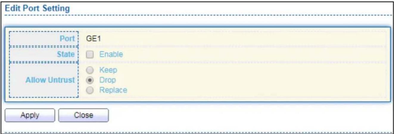
text_image
Edit Port Setting Port GE1 State Enable Allow Untrust Keep Drop Replace Apply CloseFigure 121 - DHCP Snooping > Opon82 Property > Edit Port Seng
| Item | Descripon |
| Port | Display selected port to be edited |
| State | Set checkbox to enable/disable opon82 funcon of interface. |
| Allow untrusted | Select the acon perform when untrusted port receive DHCP packet has opon82 led. Default is drop.Keep: Keep original opon82 content.Replace: Replace opon82 content by switch sengDrop: Drop packets with opon82 |
IV-10-8-4 Opon82 Circuit ID
This page allows user to set string of DHCP opon82 circuit ID led. The string will each in opon82 if opon inserted.
To display Opon82 Circuit ID page, click Security > DHCP Snooping > Opon82 Circuit ID.
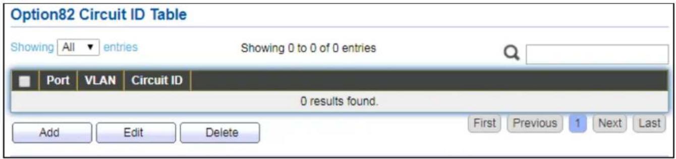
text_image
Option82 Circuit ID Table Showing All entries Showing 0 to 0 of 0 entries Port VLAN Circuit ID 0 results found. Add Edit Delete First Previous 1 Next LastFigure 122 - Security > DHCP Snooping > Opon82 Circuit ID
| Item | Descripon |
| Port | Display port ID of entry. |
| VLAN | Display associate VLAN of entry. |
| Circuit ID | Display circuit ID string of entry. |
Click "Add" buon or "Edit" buon to view the Add/Edit Opon82 Circuit ID menu.
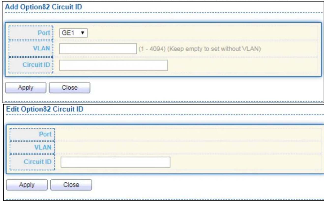
text_image
Add Option82 Circuit ID Port GE1 VLAN (1 - 4094) (Keep empty to set without VLAN) Circuit ID Apply Close Edit Option82 Circuit ID Port VLAN Circuit ID Apply CloseFigure 123 - Security > DHCP Snooping > Opon82 Circuit ID > Add/Edit Opon82 Circuit ID
| Item | Descripon |
| Port | Select port from list to associate to CID entry. Only available on Add dialog. |
| VLAN | Input VLAN ID to associate to circuit ID entry. VLAN ID is not mandatory. Only available on Add dialog. |
| Circuit ID | Input String as circuit ID. Packets match port and VLAN will be inserted circuit ID. |
IV-10-9 IP Source Guard
Use the IP Source Guard pages to congregate sengs of IP Source Guard.
IV-10-9-1 Port Seng
Use the IP Source Guard pages to congregate sengs of IP Source Guard.
To display Port Seing page, click Security > IP Source Guard > Port Seng.
| Entry | Port | State | Verify Source | Current Entry | Max Entry |
| 1 | GE1 | Disabled | IP | 0 | Unlimited |
| 2 | GE2 | Disabled | IP | 0 | Unlimited |
| 3 | GE3 | Disabled | IP | 0 | Unlimited |
| 4 | GE4 | Disabled | IP | 0 | Unlimited |
| 5 | GE5 | Disabled | IP | 0 | Unlimited |
| 6 | GE6 | Disabled | IP | 0 | Unlimited |
| 7 | GE7 | Disabled | IP | 0 | Unlimited |
| 8 | GE8 | Disabled | IP | 0 | Unlimited |
| 9 | GE9 | Disabled | IP | 0 | Unlimited |
| 10 | GE10 | Disabled | IP | 0 | Unlimited |
| 11 | GE11 | Disabled | IP | 0 | Unlimited |
| 12 | GE12 | Disabled | IP | 0 | Unlimited |
| 13 | GE13 | Disabled | IP | 0 | Unlimited |
| 14 | GE14 | Disabled | IP | 0 | Unlimited |
| 15 | GE15 | Disabled | IP | 0 | Unlimited |
| 16 | GE16 | Disabled | IP | 0 | Unlimited |
| 17 | GE17 | Disabled | IP | 0 | Unlimited |
| 18 | GE18 | Disabled | IP | 0 | Unlimited |
| 19 | GE19 | Disabled | IP | 0 | Unlimited |
| 20 | GE20 | Disabled | IP | 0 | Unlimited |
| 21 | GE21 | Disabled | IP | 0 | Unlimited |
| 22 | GE22 | Disabled | IP | 0 | Unlimited |
| 23 | GE23 | Disabled | IP | 0 | Unlimited |
| 24 | GE24 | Disabled | IP | 0 | Unlimited |
| 25 | GE25 | Disabled | IP | 0 | Unlimited |
| 26 | GE26 | Disabled | IP | 0 | Unlimited |
| 27 | GE27 | Disabled | IP | 0 | Unlimited |
| 28 | GE28 | Disabled | IP | 0 | Unlimited |
| 29 | LAG1 | Disabled | IP | 0 | Unlimited |
| 30 | LAG2 | Disabled | IP |
Figure 124 Security > IP Source Guard > Port Seng
| Item | Descripon |
| Port | Display port ID. |
| State | Display IP Source Guard enable/disable status of interface. |
| Verify Source | Display mode of IP Source Guard vericaon |
| Current Binding Entry | Display current binding entries of a interface. |
| Max Binding Entry | Display the number of maximum binding entry of interface. |
Click "Edit" buon to view the Edit Port Seng menu.

text_image
Edit Port Setting Port GE1 State Enable Verify Source IP IP-MAC Max Entry 0 (0 - 50, default 0), 0 is Unlimited Apply CloseFigure 125 - Security > IP Source Guard > Port Seng > Edit Port Seng
| Item | Descripon |
| Port | Display selected port to be edited. |
| Status | Set checkbox to enable or disable IP Source Guard funcon. Default is disabled. |
| Verify Source | Select the mode of IP Source Guard vericaonIP: Only verify source IP address of packet.IP-MAC: Verify source IP and source MAC address of packet. |
| Max Entry | Input the maximum number of entries that a port can be bounded.Default is un-limited on all ports. No entry will be bound if limitaon reached. |
IV-10-9-2 IMPV Binding
This page allows user to add stac IP source guard entry and browse all IP source guard entries that learned by DHCP snooping or stacally create by user.
To display IPMV Binding page, click Security > IP Source Guard > IMPV Binding.
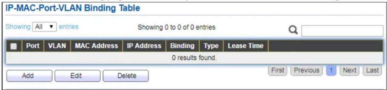
text_image
IP-MAC-Port-VLAN Binding Table Showing All entries Showing 0 to 0 of 0 entries Port VLAN MAC Address IP Address Binding Type Lease Time 0 results found. Add Edit Delete First Previous 1 Next LastFigure 126 - Security > IP Source Guard > IMPV Binding
| Item | Descripon |
| Port | Display port ID of entry. |
| VLAN | Display VLAN ID of entry. |
| MAC Address | Display MAC address of entry. Only available of IP-MAC binding entry. |
| IP Address | Display IP address of entry. Mask always to be 255.255.255.255 for IP-MAC binding. IP binding entry display user input. |
| Binding | Display binding type of entry. |
| Type | Type of exisng binding entry● Stac: Entry added by user.● Dynamic: Entry learned by DHCP snooping. |
| Lease Time | Lease me of DHCP Snooping learned entry. Aer lease me entry will be deleted. Only available of dynamic entry. |
Click "Add" or "Edit" buon to view the Add/Edit IP-MAC-Port-VLAN Binding menu.

text_image
Add IP-MAC-Port-VLAN Binding Port GE1 ▼ VLAN (1 - 4094) Binding ● IP-MAC-Port-VLAN ● IP-Port-VLAN MAC Address IP Address / 255.255.255.255 Apply Close Edit IP-MAC-Port-VLAN Binding Port GE1 ▼ VLAN 20 Binding IP-MAC-Port-VLAN MAC Address 00:11:22:33:44:55 IP Address 192.168.2.33 / 255.255.255.255 Apply CloseFigure 127 - Security > IP Source Guard > Add/Edit IP-MAC-Port-VLAN Binding
| Item | Descripon |
| Port | Select port from list of a binding entry. |
| VLAN | Specify a VLAN ID of a binding entry. |
| Binding | Select matching mode of binding entryIP-MAC-Port-VLAN: packet must match IP address、MAC address、Port and VLAN ID.IP-Port-VLAN: packet must match IP address or subnet、Port and VLAN ID. |
| MAC Address | Input MAC address. Only available on IP-MAC-Port-VLAN mode. |
| IP Address | Input IP address and mask. Mask only available on IP-MAC-Port mode. |
IV-10-9-3 Save Database
This page allows user to congregate DHCP snooping database which can backup and restore dynamic DHCP snooping entries.
To display Save Database page, click Security > DHCP Snooping > Save Database.
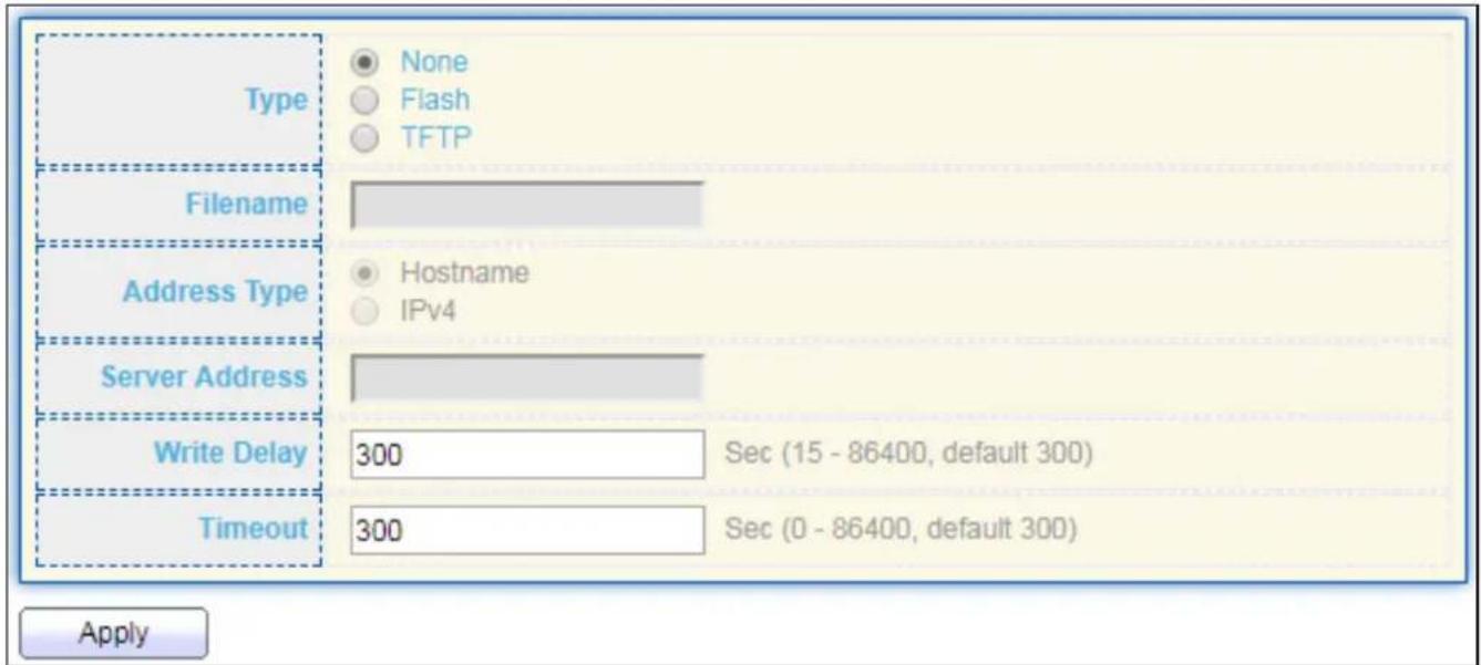
text_image
Type None Flash TFTP Filename Address Type Hostname IPv4 Server Address Write Delay 300 Sec (15 - 86400, default 300) Timeout 300 Sec (0 - 86400, default 300) ApplyFigure 128 - Security > IP Source Guard > Save Database
| Item | Descripon |
| Type | Select the type of database agent.● None: Disable database agent service.● Flash: Save DHCP dynamic binding entries to ash.● TFTP: Save DHCP dynamic binding entries to remote TFTP server. |
| Filename | Input lename for backup le. Only available when selecng type “ash” and “TFTP”. |
| Address Type | Select the type of TFTP server.● Hostname: TFTP server address is hostname.● IPv4: TFTP server address is IPv4 address |
| Server Address | Input remote TFTP server hostname or IP address. Only available when selecng type “TFTP” |
| Write Delay | Input delay mer for doing backup aer change happened. Default is 300 seconds. |
| Timeout | Input aborts meout for doing backup failure. Default is 300 seconds. |
IV-11 ACL
Use the ACL pages to congregate sengs for the switch ACL features..
IV-11-1 MAC ACL
This page allows user to add or delete ACL rule. A rule cannot be deleted if under binding.
To display MAC ACL page, click ACL > MAC ACL.

text_image
ACL Name Apply ACL Table Showing All entries Showing 0 to 0 of 0 entries ACL Name Rule Port 0 results found. Delete First Previous 1 Next LastFigure 129 - ACL > MAC ACL
| Item | Descripon |
| ACL Name | Input MAC ACL name. |
| ACL Name | Display MAC ACL name. |
| Rule | Display the number ACE rule of ACL. |
| Port | Display the port list that bind this ACL. |
IV-11-2 MAC ACE
This page allows user to add, edit or delete ACE rule. An ACE rule cannot be edited or deleted if ACL under binding. New ACE cannot be added if ACL under binding.
To display MAC ACE page, click ACL > MAC ACE.

text_image
ACE Table ACL Name None ▼ Showing All ▼ entries Showing 0 to 0 of 0 entries Sequence Action Source MAC Destination MAC Ethertype VLAN 802.1p Address Mask Address Mask Value Mask 0 results found. First Previous 1 Next LastFigure 130 - ACL > MAC ACE
| Item | Descripon |
| ACL Name | Select the ACL name to which an ACE is being added. |
| Sequence | Display the sequence of ACE. |
| Acon | Display the acon of ACE. |
| Source MAC | Display the source MAC address and mask of ACE. |
| Desnaon MAC | Display the desnaon MAC address and mask of ACE. |
| Ethertype | Display the Ethernet frame type of ACE. |
| VLAN ID | Display the VLAN ID of ACE. |
| 802.1p Value | Display the 802.1p value of ACE. |
| 802.1p Mask | Display the 802.1p mask of ACE. |
Click "Edit" buon to view the Edit ACE menu.
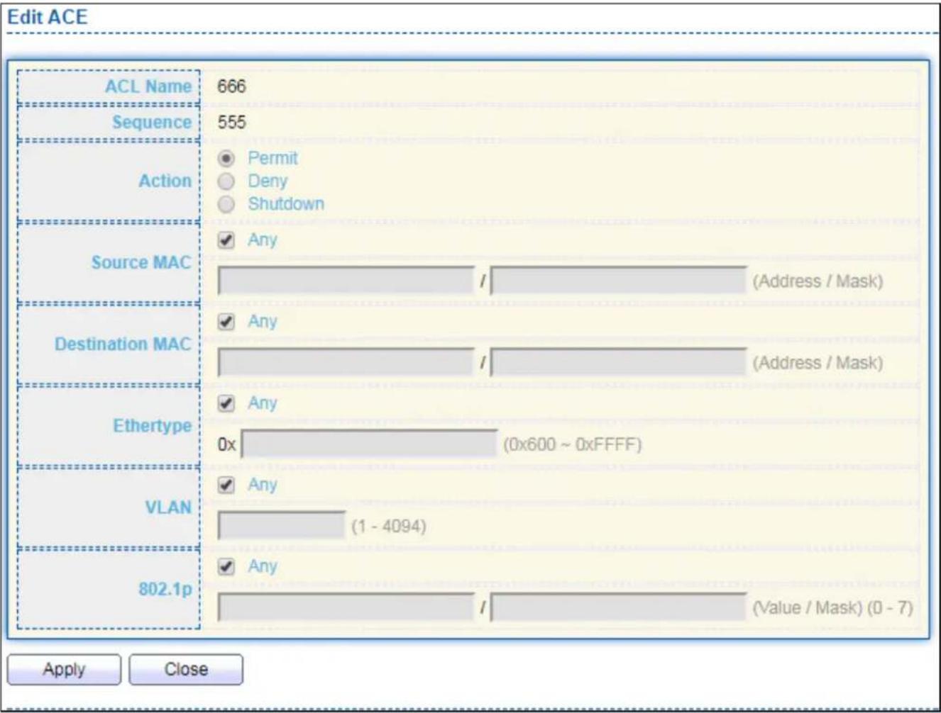
bar
| ACL Name | Value | | :--- | :--- | | ACL Name | 666 | | Sequence | 555 | | Action | Permit | | Action | Deny | | Action | Shutdown | | Source MAC | Any | | Source MAC | / (Address / Mask) | | Destination MAC | Any | | Destination MAC | / (Address / Mask) | | Ethertype | Any | | Ethertype | 0x (0x600 ~ 0xFFFF) | | VLAN | Any | | VLAN | (1 - 4094) | | 802.1p | Any | | 802.1p | / (Value / Mask) (0 - 7) | Apply CloseFigure 131 - ACL > Edit ACE
| Item | Descripon |
| ACL Name | Display the ACL name to which an ACE is being added.. |
| Sequence | Specify the sequence of the ACE. ACEs with higher sequence are processed rst (1 is the highest priority). Only available on Add Dialog. |
| Acon | Select the acon aer ACE match packet.● Permit: Forward packets that meet the ACE criteria.● Deny: Drop packets that meet the ACE criteria.● Shutdown: Drop packets that meet the ACE criteria, and disable the port from where the packets were received. Such ports can be reacvated from the Port Sengs page. |
| Source MAC | Select the type for source MAC address.● Any: All source addresses are acceptable.● User Dened: Only a source address or a range of source addresses which users dene are acceptable. Enter the source MAC address and mask to which will be matched. |
| Desnaon MAC | Select the type for Desnaon MAC address.● Any: All desnaon addresses are acceptable.● User Dened: Only a desnaon address or a range of desnaon addresses which users dene are acceptable. Enter the desnaon MAC address and mask to which will be matched. |
| Ethertype | Select the type for Ethernet frame type.● Any: All Ethernet frame type is acceptable.● User Dened: Only an Ethernet frame type which users dene is acceptable. Enter the Ethernet frame type value to which will be matched. |
| VLAN | Select the type for VLAN ID.● Any: All VLAN ID is acceptable.● User Dened: Only a VLAN ID which users dene is acceptable.Enter the VLAN ID to which will be matched. |
| 802.1p | Select the type for 802.1p value.● Any: All 802.1p value is acceptable.● User Dened: Only an 802.1p value or a range of 802.1p value which users dene is acceptable. Enter the 802.1p value and mask to which will be matched. |
IV-11-3 IPv4 ACL
This page allows user to add or delete IPv4 ACL rule. A rule cannot be deleted if under binding.
To display IPv4 ACL page, click ACL > IPv4 ACL.

text_image
ACL Name Apply ACL Table Showing All entries Showing 0 to 0 of 0 entries ACL Name Rule Port 0 results found. Delete First Previous 1 Next LastFigure 132 - ACL > IPv4 ACL
| Item | Descripon |
| ACL Name | Input IPv4 ACL name. |
| ACL Name | Display IPv4 ACL name. |
| Rule | Display the number ACE rule of ACL. |
| Port | Display the port list that bind this ACL. |
IV-11-4 IPv4 ACE
This page allows user to add, edit or delete ACE rule. An ACE rule cannot be edited or deleted if ACL under binding. New ACE cannot be added if ACL under binding.
To display IPv4 ACE page, click ACL > IPv4 ACE.
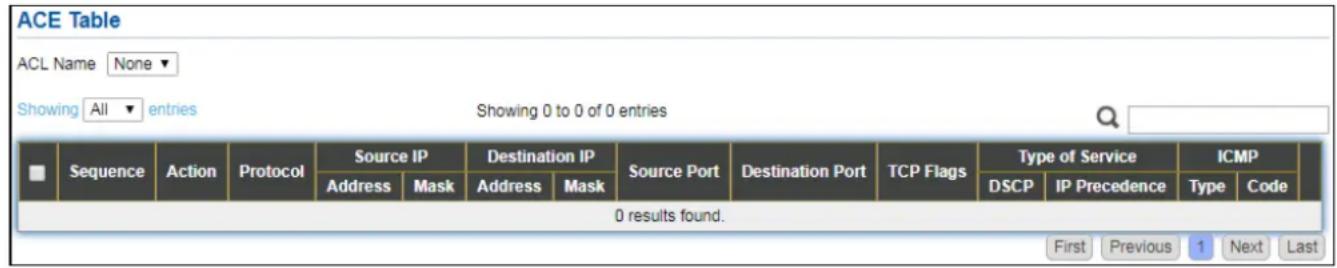
text_image
ACE Table ACL Name None Showing All entries Showing 0 to 0 of 0 entries Sequence Action Protocol Source IP Destination IP Source Port Destination Port TCP Flags Type of Service ICMP Address Mask Address Mask DSCP IP Precedence Type Code 0 results found. First Previous 1 Next LastFigure 133 - ACL > IPv4 ACE
| Item | Descripon |
| ACL Name | Select the ACL name to which an ACE is being added. |
| Sequence | Display the sequence of ACE. |
| Acon | Display the acon of ACE. |
| Protocol | Display the protocol value of ACE. |
| Source IP | Display the source IP address and mask of ACE. |
| Desnaon IP | Display the desnaon IP address and mask of ACE. |
| Source Port | Display single source port or a range of source ports of ACE. Only available when protocol is TCP or UDP. |
| Desnaon Port | Display single desnaon port or a range of desnaon ports of ACE. Only available when protocol is TCP or UDP. |
| TCP Flags | Display the TCP ag value if ACE. Only available when protocol is TCP. |
| Type of Service | Display the ToS value of ACE which could be DSCP or IP Precedence. |
| ICMP | Display the ICMP type and code of ACE. Only available when protocol is ICMP. |
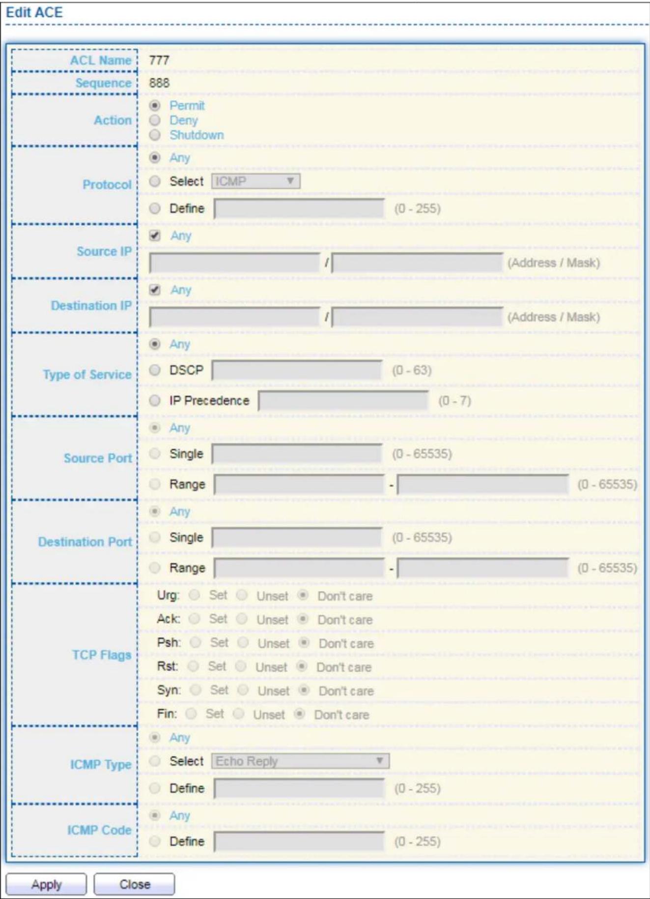
bar
| ACL Name | Count | | :--- | :--- | | ACL Name | 777 | | Sequence | 888 | | Action | Permit | | Action | Deny | | Action | Shutdown | | Protocol | Any | | Protocol | Select ICMP | | Protocol | Define (0 - 255) | | Source IP | Any (Address / Mask) | | Source IP | Any (Address / Mask) | | Destination IP | Any (Address / Mask) | | Type of Service | Any DSCP (0 - 63) IP Precedence (0 - 7) | | Source Port | Any Single (0 - 65535) Range (0 - 65535) | | Destination Port | Any Single (0 - 65535) Range (0 - 65535) | | TCP Flags | Urg: Set Unset Don't care Ack: Set Unset Don't care Psh: Set Unset Don't care Rst: Set Unset Don't care Syn: Set Unset Don't care Fin: Set Unset Don't care | | ICMP Type | Any Select Echo Reply Define (0 - 255) | | ICMP Code | Any Define (0 - 255) | Apply CloseFigure 134 - ACL > Add/Edit ACE
| Item | Descripon |
| ACL Name | Display the ACL name to which an ACE is being added. |
| Sequence | Specify the sequence of the ACE. ACEs with higher sequence are processed rst (1 is the highest sequence). Only available on Add dialog. |
| Acon | Select the acon for a match.● Permit: Forward packets that meet the ACE criteria.● Deny: Drop packets that meet the ACE criteria.● Shutdown: Drop packets that meet the ACE criteria, and disable the port from where the packets were received. Such ports can be reacvated from the Port Sengs page. |
| Protocol | Select the type of protocol for a match.● Any (IP): All IP protocols are acceptable.● Select from list: Select one of the following protocols from the drop-down list.ICMP/IPinIP/TCP/EGP/IGP/UDP/HMP/RDP/IPV6/IPV6:ROUT/IPV6:FRAG/RSVP/IPV6:ICMP/OSPF/PIM/L2TP● Protocol ID to match: Enter the protocol ID. |
| Source IP | Select the type for source IP address.● Any: All source addresses are acceptable.● User Dened: Only a source address or a range of source addresses which users dene are acceptable. Enter the source IP address value and mask to which will be matched. |
| Desnaon IP | Select the type for desnaon IP address.● Any: All desnaon addresses are acceptable.● User Dened: Only a desnaon address or a range of desnaon addresses which users dene are acceptable. Enter the desnaon IP address value and mask to which will be matched. |
| Source Port | Select the type of protocol for a match. Only available when protocol is TCP or UDP.● Any: All source ports are acceptable.● Single: Enter a single TCP/UDP source port to which packets are matched.● Range: Select a range of TCP/UDP source ports to which the packet is matched. There are eight dierent port ranges that can be congured (shared between source and desnaon ports). TCP and UDP protocols each have eight port ranges. |
| Desnaon Port | Select the type of protocol for a match. Only available when protocol is TCP or UDP.● Any: All source ports are acceptable.● Single: Enter a single TCP/UDP source port to which packets are matched.● Range: Select a range of TCP/UDP source ports to which the packet is matched. There are eight dierent port ranges that can becongured (shared between source and desnaon ports). TCP and UDP protocols each have eight port ranges. |
| TCP Flags | Select one or more TCP ags with which to iter packets. Filtered packets are either forwarded or dropped. Filtering packets by TCP ags increases packet control, which increases network security. Only available when protocol is TCP. |
| Type of Service | Select the type of service for a match.Any: All types of service are acceptable.DSCP to match: Enter a Dierenated Serves Code Point (DSCP) to match.IP Precedence to match: Enter a IP Precedence to match. |
| ICMP Type | Either select the message type by name or enter the message type number. Only available when protocol is ICMP.Any: All message types are acceptable.Select from list: Select message type by name.Protocol ID to match: Enter the number of message type. |
| ICMP Code | Select the type for ICMP code. Only available when protocol is ICMP.Any: All codes are acceptable.User Dened: Enter an ICMP code to match. |
IV-11-5 ACL Binding
This page allows user to bind or unbind ACL rule to or from interface. IPv4 and lpv6 ACL cannot be bound to the same port simultaneously.
To display ACL Binding page, click ACL > ACL Binding.
| Entry | Port | MAC ACL | IPv4 ACL | IPv6 ACL |
| 1 | GE1 | |||
| 2 | GE2 | |||
| 3 | GE3 | |||
| 4 | GE4 | |||
| 5 | GE5 | |||
| 6 | GE6 | |||
| 7 | GE7 | |||
| 8 | GE8 | |||
| 9 | GE9 | |||
| 10 | GE10 | |||
| 11 | GE11 | |||
| 12 | GE12 | |||
| 13 | GE13 | |||
| 14 | GE14 | |||
| 15 | GE15 | |||
| 16 | GE16 | |||
| 17 | GE17 | |||
| 18 | GE18 | |||
| 19 | GE19 | |||
| 20 | GE20 | |||
| 21 | GE21 | |||
| 22 | GE22 | |||
| 23 | GE23 | |||
| 24 | GE24 | |||
| 25 | GE25 | |||
| 26 | GE26 | |||
| 27 | GE27 | |||
| 28 | GE28 | |||
| 29 | LAG1 | |||
| 30 | LAG2 | |||
| 31 | LAG3 | |||
| 32 | LAG4 | |||
| 33 | LAG5 | |||
| 34 | LAG6 | |||
| 35 | LAG7 | |||
| 36 | LAG8 |
Figure 135 - ACL > ACL Binding
| Item | Descripon |
| Port | Display port entry ID. |
| MAC ACL | Display mac ACL name that bound of interface. Empty means no rule bound. |
| IPv4 ACL | Display ipv4 ACL name that bound of interface. Empty means no rule bound. |
| IPv6 ACL | Display ipv6 ACL name that bound of interface. Empty means no rule bound. |
Click "Edit" buon to view the Edit ACL Binding menu.

text_image
Add ACL Binding Port GE1 Note: ACL without any rules cannot be bound MAC ACL None ▼ IPv4 ACL None ▼ IPv6 ACL None ▼ Apply CloseFigure 136 - ACL > Edit ACL Binding
| Item | Descripon |
| Port | Display port entry ID. |
| MAC ACL | Select mac ACL name from list to bind. |
| IPv4 ACL | Select IPv4 ACL name from list to bind. |
| IPv6 ACL | Select IPv6 ACL name from list to bind. |
IV-12 QoS
Use the QoS pages to congregate sengs for the switch QoS interface.
IV-12-1 General
Use the QoS general pages to congregate sengs for general purpose.
IV-12-1-1 Property
To display Property web page, click QoS > General > Property.
| State | Enable | |||||||
| Trust Mode | CoS DSCP CoS-DSCP IP Precedence | |||||||
| Apply | ||||||||
| Port Setting Table | ||||||||
| Q | ||||||||
| Entry | Port | CoS | Trust | Remarking | ||||
| CoS | DSCP | IP Precedence | ||||||
| 1 | GE1 | 0 | Enabled | Disabled | Disabled | Disabled | ||
| 2 | GE2 | 0 | Enabled | Disabled | Disabled | Disabled | ||
| 3 | GE3 | 0 | Enabled | Disabled | Disabled | Disabled | ||
| 4 | GE4 | 0 | Enabled | Disabled | Disabled | Disabled | ||
| 5 | GE5 | 0 | Enabled | Disabled | Disabled | Disabled | ||
| 6 | GE6 | 0 | Enabled | Disabled | Disabled | Disabled | ||
| 7 | GE7 | 0 | Enabled | Disabled | Disabled | Disabled | ||
| 8 | GE8 | 0 | Enabled | Disabled | Disabled | Disabled | ||
| 9 | GE9 | 0 | Enabled | Disabled | Disabled | Disabled | ||
| 10 | GE10 | 0 | Enabled | Disabled | Disabled | Disabled | ||
| 11 | GE11 | 0 | Enabled | Disabled | Disabled | Disabled | ||
| 12 | GE12 | 0 | Enabled | Disabled | Disabled | Disabled | ||
| 13 | GE13 | 0 | Enabled | Disabled | Disabled | Disabled | ||
| 14 | GE14 | 0 | Enabled | Disabled | Disabled | Disabled | ||
| 15 | GE15 | 0 | Enabled | Disabled | Disabled | Disabled | ||
| 16 | GE16 | 0 | Enabled | Disabled | Disabled | Disabled | ||
| 17 | GE17 | 0 | Enabled | Disabled | Disabled | Disabled | ||
| 18 | GE18 | 0 | Enabled | Disabled | Disabled | Disabled | ||
| 19 | GE19 | 0 | Enabled | Disabled | Disabled | Disabled | ||
| 20 | GE20 | 0 | Enabled | Disabled | Disabled | Disabled | ||
| 21 | GE21 | 0 | Enabled | Disabled | Disabled | Disabled | ||
| 22 | GE22 | 0 | Enabled | Disabled | Disabled | Disabled | ||
| 23 | GE23 | 0 | Enabled | Disabled | Disabled | Disabled | ||
| 24 | GE24 | 0 | Enabled | Disabled | Disabled | Disabled | ||
| 25 | GE25 | 0 | Enabled | Disabled | Disabled | Disabled | ||
| 26 | GE26 | 0 | Enabled | Disabled | Disabled | Disabled | ||
| 27 | GE27 | 0. Enabled. Disabled. Disabled. Disabled. Disabled. Disabled. Disabled. Disabled. Disabled. Disabled. Disabled. Disabled. Disabled. Disabled. Disabled. Disabled. Disabled. Disabled. Disabled. Disabled. Disabled. Disabled. Disabled. Disabled. Disabled. Disabled. Disabled. Disabled. Disabled. Disabled. Disabled. Disabled. Disabled. Disabled. Disabled. Disabled. Disabled. Disabled. Disabled. Disabled. Disabled. Disabled. Disabled. Disabled. Disabled. Disabled. Disabled. Disabled. Disabled. Disabled. Disabled. Disabled from the State to the Port Setting Table (a) | ||||||
Figure 137 - QoS > General > Property
| Item | Descripon |
| State | Set checkbox to enable/disable QoS. |
| Trust | Select QoS trust modeCoS: Trac is mapped to queues based on the CoS eld in the VLAN tag, or based on the per-port default CoS value (if there is no VLAN tag on the incoming packet), the actual mapping of the CoS to queue can be congured on port seng dialog.CoS-DSCP: Uses the trust CoS mode for non-IP trac and trust DSCP mode for IP trac.IP Precedence: Trac is mapped to queues based on the IP precedence. The actual mapping of the IP precedence to queue can be congured on the IP Precedence mapping page. |
| Port Seng Table | |
| Port | Port name |
| CoS | Port default CoS priority value for the selected ports. |
| Trust | Port trust stateEnabled: Trac will follow trust mode in global sengDisabled: Trac will always use best eorts |
| Remarking (CoS) | Set checkbox to enable/disable port CoS remarking.Enabled: CoS remarking is enabledDisabled: CoS remarking is disabled |
| Remarking (IP Precedence) | Set checkbox to enable/disable port IP Precedence remarking.Enabled: DSCP remarking is enabledDisabled: DSCP remarking is disabled |
Click "Edit" buon to view the Edit Port Seng menu.

text_image
Edit Port Setting Port GE1 CoS 0 (0 - 7) Trust Enable Remarking CoS Enable DSCP Enable IP Precedence Enable Apply CloseFigure 138 - Qos > General > Property
| Item | Descripon |
| Port | Selected port list. |
| CoS | Set default CoS/802.1p priority value for the selected ports. |
| Trust | Set checkbox to enable/disable port trust state. |
| Remarking (CoS) | Set checkbox to enable/disable port CoS remarking. |
| Remarking (IP Precedence) | Set checkbox to enable/disable port IP Precedence remarking. |
IV-12-1-2 Queue Scheduling
The switch supports eight queues for each interface. Queue number 8 is the highest priority queue.
Queue number 1 is the lowest priority queue. There are two ways of determining how trac in queues is handled, Strict Priority (SP) and Weighted Round Robin (WRR).
- Strict Priority (SP)—Egress trac from the highest priority queue is transmied rst. Trac from the lower queues is processed only aer the highest queue has been transmied, which provide the highest level of priority of trac to the highest numbered queue.
- Weighted Round Robin (WRR)—In WRR mode the number of packets sent from the queue is proportional to the weight of the queue (the higher the weight, the more frames are sent).
The queuing modes can be selected on the Queue page. When the queuing mode is by Strict Priority, the priority sets the order in which queues are serviced, starng with queue_8 (the highest priority queue) and going to the next lower queue when each queue is completed.
When the queuing mode is Weighted Round Robin, queues are serviced until their quota has been used up and then another queue is serviced. It is also possible to assign some of the lower queues to WRR, while keeping some of the higher queues in Strict Priority. In this case trac for the SP queues is always sent before trac from the WRR queues. Aer the SP queues have been emped, trac from the WRR queues is forwarded. (The relave poron from each WRR queue depends on its weight).
To display Queue Scheduling web page, click QoS > General > Queue Scheduling
| Queue | Method | ||||
| Strict Priority | WRR | Weight | WRR Bandwidth (%) | ||
| 1 | ◎ | ○ | 1 | ||
| 2 | ◎ | ○ | 2 | ||
| 3 | ◎ | ○ | 3 | ||
| 4 | ◎ | ○ | 4 | ||
| 5 | ◎ | ○ | 5 | ||
| 6 | ◎ | ○ | 9 | ||
| 7 | ◎ | ○ | 13 | ||
| 8 | ◎ | ○ | 15 | ||
Figure 139 - QoS > General > Queue Scheduling
| Item | Descripon |
| Queue | Queue ID to congure. |
| Strict Priority | Set queue to strict priority type. |
| WRR | Set queue to Weight round robin type. |
| Weight | If the queue type is WRR, set the queue weight for the queue. |
| WRR Bandwidth | Percentage of WRR queue bandwidth. |
IV-12-1-3 CoS Mapping
The CoS to Queue table determines the egress queues of the incoming packets based on the 802.1p priority in their VLAN tags. For incoming untagged packets, the 802.1p priority will be the default CoS/802.1p priority assigned to the ingress ports. Use the Queues to CoS table to remark the CoS/802.1p priority for egress trac from each queue.
To display CoS Mapping web page, click QoS > General > CoS Mapping.

text_image
CoS to Queue Mapping CoS Queue 0 2▼ 1 1▼ 2 3▼ 3 4▼ 4 5▼ 5 6▼ 6 7▼ 7 8▼ Apply Queue to CoS Mapping Queue CoS 1 1▼ 2 0▼ 3 2▼ 4 3▼ 5 4▼ 6 5▼ 7 6▼ 8 7▼ ApplyFigure 140 - QoS > General > Cos Mapping
| Item | Descripon |
| CoS to Queue Mapping | |
| CoS | CoS value. |
| Queue | Select queue id for the CoS value. |
| Queue to CoS Mapping | |
| Queue | Queue ID |
| CoS | Select CoS value for the queue id. |
IV-12-1-4 IP Precedence Mapping
This page allows user to congregate IP Precedence to Queue mapping and Queue to IP Precedence mapping.
To display IP Precedence Mapping web page, click QoS > General > IP Precedence Mapping.
| IP Precedence to Queue Mapping | |
| IP Precedence | Queue |
| 0 | 1▼ |
| 1 | 2▼ |
| 2 | 3▼ |
| 3 | 4▼ |
| 4 | 5▼ |
| 5 | 6▼ |
| 6 | 7▼ |
| 7 | 8▼ |
| Apply | |
| Queue to IP Precedence Mapping | |
| Queue | IP Precedence |
| 1 | 0▼ |
| 2 | 1▼ |
| 3 | 2▼ |
| 4 | 3▼ |
| 5 | 4▼ |
| 6 | 5▼ |
| 7 | 6▼ |
| 8 | 7▼ |
| Apply | |
| Item | Descripon |
| IP Precedence to Queue Mapping | |
| IP Precedence | IP Precedence value. |
| Queue | Queue value which IP Precedence is mapped. |
| Queue to IP Precedence Mapping | |
| Queue | Queue ID. |
| IP Precedence | IP Precedence value which queue is mapped. |
Figure 141 - QoS > General > IP Precedence Mapping
IV-12-2 Rate Limit
Use the Rate Limit pages to dene values that determine how much trac the switch can receive and send on specic port or queue.
IV-12-2-1 Ingress/Egress Port
This page allows user to congregate ingress port rate limit and egress port rate limit. The ingress rate limit is the number of bits per second that can be received from the ingress interface. Excess bandwidth above this limit is discarded.
To display Ingress / Egress Port web page, click QoS > Rate Limit > Ingress / Egress Port.
| Ingress / Egress Port Table | |||||||
| Q | |||||||
| Entry | Port | Ingress | Egress | ||||
| State | Rate (Kbps) | State | Rate (Kbps) | ||||
| 1 | GE1 | Disabled | Disabled | ||||
| 2 | GE2 | Disabled | Disabled | ||||
| 3 | GE3 | Disabled | Disabled | ||||
| 4 | GE4 | Disabled | Disabled | ||||
| 5 | GE5 | Disabled | Disabled | ||||
| 6 | GE6 | Disabled | Disabled | ||||
| 7 | GE7 | Disabled | Disabled | ||||
| 8 | GE8 | Disabled | Disabled | ||||
| 9 | GE9 | Disabled | Disabled | ||||
| 10 | GE10 | Disabled | Disabled | ||||
| 11 | GE11 | Disabled | Disabled | ||||
| 12 | GE12 | Disabled | Disabled | ||||
| 13 | GE13 | Disabled | Disabled | ||||
| 14 | GE14 | Disabled | Disabled | ||||
| 15 | GE15 | Disabled | Disabled | ||||
| 16 | GE16 | Disabled | Disabled | ||||
| 17 | GE17 | Disabled | Disabled | ||||
| 18 | GE18 | Disabled | Disabled | ||||
| 19 | GE19 | Disabled | Disabled | ||||
| 20 | GE20 | Disabled | Disabled | ||||
| 21 | GE21 | Disabled | Disabled | ||||
| 22 | GE22 | Disabled | Disabled | ||||
| 23 | GE23 | Disabled | Disabled | ||||
| 24 | GE24 | Disabled | Disabled | ||||
| 25 | GE25 | Disabled | Disabled | ||||
| 26 | GE26 | Disabled | Disabled | ||||
| 27 | GE27 | Disabled | Disabled | ||||
| 28 | GE28 | Disabled | Disabled | ||||
Figure 142 - QoS > Rate Limit > Ingress / Egress Port
| Item | Descripon |
| Port | Port name. |
| Ingress (State) | Port ingress rate limit state● Enabled: Ingress rate limit is enabled● Disabled: Ingress rate limit is disabled |
| Ingress (Rate) | Port ingress rate limit value if ingress rate state is enabled. |
| IP Precedence | IP Precedence value which queue is mapped. |
| Egress (State) | Port egress rate limit state● Enabled: Egress rate limit is enabled● Disabled: Egress rate limit is disabled |
| Egress (Rate) | Port egress rate limit value if egress rate state is enabled. |
Click "Edit" buon to view the Ingress / Egress Port menu.
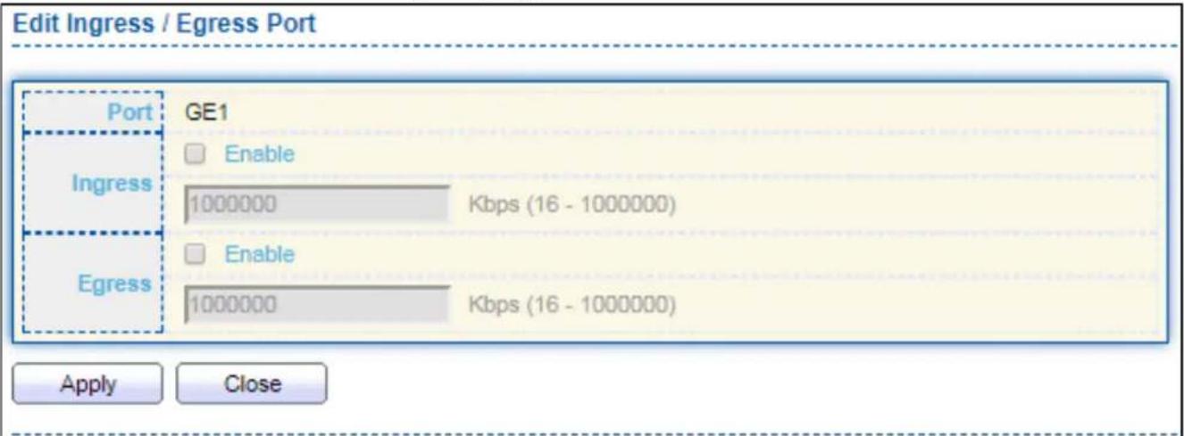
text_image
Edit Ingress / Egress Port Port GE1 Ingress □ Enable 1000000 Kbps (16 - 1000000) Egress □ Enable 1000000 Kbps (16 - 1000000) Apply CloseFigure 143 - QoS > Rate Limit > Ingress / Egress Port
| Item | Descripon |
| Port | Select port list. |
| Ingress | Set checkbox to enable/disable ingress rate limit. If ingress rate limit is enabled, rate limit value need to be assigned. |
| Egress | Set checkbox to enable/disable egress rate limit. If egress rate limit is enabled, rate limit value need to be assigned. |
IV-13 Diagnoscs
Use the Diagnoscs pages to congregate sengs for the switch diagnoses feature or operang diagnosis ulies.
IV-13-1 Logging
IV-13-1-1 Property
To enable/disable the logging service, click Diagnosc > Logging > Property.
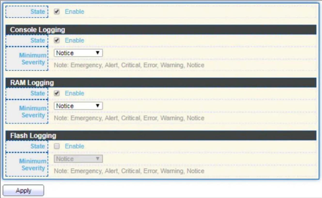
text_image
State Enable Console Logging State Enable Minimum Severity Notice Note: Emergency, Alert, Critical, Error, Warning, Notice RAM Logging State Enable Minimum Severity Notice Note: Emergency, Alert, Critical, Error, Warning, Notice Flash Logging State Enable Minimum Severity Notice Note: Emergency, Alert, Critical, Error, Warning, Notice ApplyFigure 144 - Diagnoscs > Logging > Property
| Item | Descripon |
| State | Enable/Disable the global logging services. When the logging service is enabled, logging conguraon of each desnaon rule can be individually congured. If the logging service is disabled, no messages will be sent to these desnaons. |
| Console Logging | |
| State | Enable/Disable the console logging service |
| Minimum Severity | The minimum severity for the console logging. |
| RAM Logging | |
| State | Enable/Disable the RAM logging service. |
| Minimum Severity | The minimum severity for the RAM logging. |
| Flash Logging | |
| State | Enable/Disable the ash logging service. |
| Minimum Severity | The minimum severity for the ash loggin. |
IV-13-1-2 Remote Server
To congregate the remote logging server, click Diagnosc > Logging > Remote Server.

text_image
Remote Server Table Entry Server Address Server Port Facility Minimum Severity 0 results found. Add Edit DeleteFigure 145 - Diagnoscs > Logging > Remote Server
| Item | Descripon |
| Server Address | The IP address of the remote logging server. |
| Server Ports | The port number of the remote logging server. |
| Facility | The facility of the logging messages. It can be one of the following values: local0, local1, local2, local3, local4, local5, local6, and local7. |
| Minimum Severity | Emergence: System is not usable.Alert: Immediate acon is needed.Crical: System is in the crical condion.Error: System is in error condionWarning: System warning has occurredNoce: System is funconing properly, but a system noce has occurred.Informaonal: Device informaon.Debug: Provides detailed informaon about an event. |
IV-13-2 Mirroring
To display Port Mirroring web page, click Diagnoscs > Mirroring.

text_image
Mirroring Table Session ID State Monitor Port Ingress Port Egress Port 1 Disabled --- --- --- 2 Disabled --- --- --- 3 Disabled --- --- --- 4 Disabled --- --- --- Edit "" Allow the monitor port to send or receive normal packetsFigure 146 - Diagnoscs > Mirroring
| Item | Descripon |
| Session ID | Select mirror session ID. |
| State | Select mirror session state : port-base mirror or disable● Enabled: Enable port based mirror● Disabled: Disable mirror. |
| Monitor Port | Select mirror session monitor port, and select whether normal packet could be sent or received by monitor port. |
| Ingress port | Select mirror session source rx ports. |
| Egress port | Select mirror session source tx ports. |
Click "Edit" buon to view the Edit Mirroring menu.

text_image
Edit Mirroring Session ID 1 State Enable Monitor Port GE1 Send or Receive Normal Packet Ingress Port Available Port Selected Port GE1 GE2 GE3 GE4 GE5 GE6 GE7 GE8 Egress Port Available Port Selected Port GE1 GE2 GE3 GE4 GE5 GE6 GE7 GE8 Apply CloseFigure 147 - Diagnoscs > Mirroring > Edit Mirroring
| Item | Descripon |
| Session ID | Selected mirror session ID. |
| State | Select mirror session state : port-base mirror or disable● Enabled: Enable port based mirror● Disabled: Disable mirror. |
| Monitor Port | Select mirror session monitor port, and select whether normal packet could be sent or received by monitor port. |
| Ingress port | Select mirror session source rx ports. |
| Egress port | Select mirror session source tx ports. |
IV-13-3 Ping
For the ping funconality, click Diagnosc > Ping.

text_image
Address Type Hostname IPv4 IPv6 Server Address Count User Defined 4 Sec (1 - 65535) Ping Stop Ping Result Packet Status Status N/A Transmit Packet 0 Receive Packet 0 Packet Lost 0% Round Trip Time Min 0.0 ms Max 0.0 ms Average 0.0 msFigure 148 - Diagnoscs > Ping
| Item | Descripon |
| Address Type | Specify the address type to “Hostname” or “IPv4”. |
| Server Address | Specify the Hostname/IPv4 address for the remote logging server. |
| Count | Specify the numbers of each ICMP ping request. |
IV-13-4 Traceroute
For trace route funconality, click Diagnosc > Traceroute.
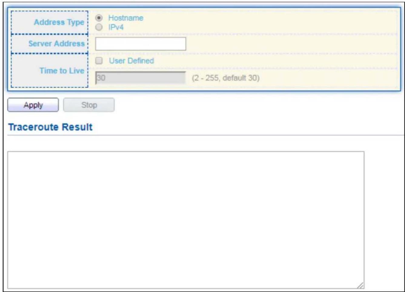
text_image
Address Type Hostname IPv4 Server Address Time to Live User Defined 30 (2 - 255, default 30) Apply Stop Traceroute ResultFigure 149 - Diagnoscs > Traceroute
| Item | Descripon |
| Address Type | Specify the address type to “Hostname” or “IPv4”. |
| Server Address | Specify the Hostname/IPv4 address for the remote logging server. |
| Time to Live | Specify the max hops of hosts for traceroute. |
IV-13-5 Copper Test
For copper length diagnosc, click Diagnosc > Copper Test.

text_image
Port GE1 Copper Test Copper Test Result Cable Status Port N/A Result N/A Length N/AFigure 150 - Diagnoscs > Logging>Copper Test
| Item | Descripon |
| Port | Specify the interface for the copper test. |
| Copper Test Result | |
| Port | The interface for the copper test. |
| Result | The status of copper test. It include:OK: Correctly terminated pair.Short Cable: Shorted pair.Open Cable: Open pair, no link partner.Impedance Mismatch: Terminang impedance is not in the reference range. |
| Length | Distance in meter from the port to the locaon on the cable where the fault was discovered. |
IV-13-6 Fiber Module
The Opcal Module Status page displays the operational informaon reported by the Small Form-factor Pluggable (SFP) transceiver. Some informaon may not be available for SFPs without the supports of digital diagnosc monitoring standard SFF-8472.
To display the Opcal Module Diagnosc page, click Diagnosc > Fiber Module.
| Port | Temperature (C) | Voltage (V) | Current (mA) | Output Power (mW) | Input Power (mW) | OE Present | Loss of Signal |
| GE25 | N/A | N/A | N/A | N/A | N/A | Remove | Loss |
| GE26 | N/A | N/A | N/A | N/A | N/A | Remove | Loss |
| GE27 | N/A | N/A | N/A | N/A | N/A | Remove | Loss |
| GE28 | N/A | N/A | N/A | N/A | N/A | Remove | Loss |
Figure 151 - Diagnoscs > Logging>Fiber Module
| Item | Descripon |
| Port | Interface or port number. |
| Temperature | Internally measured transceiver temperature. |
| Voltage | Internally measured supply voltage. |
| Current | Measured TX bias current. |
| Output Power | Measured TX output power in milliwas. |
| Input Power | Measured RX received power in milliwas. |
| Transmier Fault | State of TX fault. |
| OE Present | Indicate transceiver has achieved power up and data is ready. |
| Loss of Signal | Loss of signal. |
| Refresh | Refresh the page. |
| Detail | The detail informaon on the specied port. |
Click "Detail" buon to view the Fiber Module Status menu
| Port | GE25 |
| OE Present | N/A |
| Loss of Signal | N/A |
| Transceiver Type | N/A |
| Connector Type | N/A |
| Ethernet Compliance Code | N/A |
| Transmission Media | N/A |
| Wavelength | N/A |
| Bitrate | N/A |
| Vendor OUI | N/A |
| Vendor Name | N/A |
| Vendor PN | N/A |
| Vendor Revision | N/A |
| Vendor SN | N/A |
| Date Code | N/A |
| Temperature (C) | N/A |
| Voltage (V) | N/A |
| Current (mA) | N/A |
| Output Power (mW) | N/A |
| Input Power (mW) | N/A |
Figure 152 - Diagnoscs > Logging>Fiber Module>Fiber Module Status
IV-13-7 UDLD
Use the UDLD pages to congregate sengs of UDLD funcon.
IV-13-7-1 Property
This page allows user to congregate global and per interface sengs of UDLD.
To display Property page, click Diagnoscs > UDLD > Property.
| Entry | Port | Mode | Bidirectional State | Operational Status | Neighbor |
| 1 | GE1 | Disabled | Unknown | 0 | |
| 2 | GE2 | Disabled | Unknown | 0 | |
| 3 | GE3 | Disabled | Unknown | 0 | |
| 4 | GE4 | Disabled | Unknown | 0 | |
| 5 | GE5 | Disabled | Unknown | 0 | |
| 6 | GE6 | Disabled | Unknown | 0 | |
| 7 | GE7 | Disabled | Unknown | 0 | |
| 8 | GE8 | Disabled | Unknown | 0 | |
| 9 | GE9 | Disabled | Unknown | 0 | |
| 10 | GE10 | Disabled | Unknown | 0 | |
| 11 | GE11 | Disabled | Unknown | 0 | |
| 12 | GE12 | Disabled | Unknown | 0 | |
| 13 | GE13 | Disabled | Unknown | 0 | |
| 14 | GE14 | Disabled | Unknown | 0 | |
| 15 | GE15 | Disabled | Unknown | 0 | |
| 16 | GE16 | Disabled | Unknown | 0 | |
| 17 | GE17 | Disabled | Unknown | 0 | |
| 18 | GE18 | Disabled | Unknown | 0 | |
| 19 | GE19 | Disabled | Unknown | 0 | |
| 20 | GE20 | Disabled | Unknown | 0 | |
| 21 | GE21 | Disabled | Unknown | 0 | |
| 22 | GE22 | Disabled | Unknown | 0 | |
| 23 | GE23 | Disabled | Unknown | 0 | |
| 24 | GE24 | Disabled | Unknown | 0 | |
| 25 | GE25 | Disabled | Unknown | 0 | |
| 26 | GE26 | Disabled | Unknown | 0 | |
| 27 | GE27 | Disabled | Unknown | 0 | |
| 28 | GE28 | Disabled | Unknown | 0 |
Figure 153 - Diagnoscs > UDLD > Property
| Item | Descripon |
| Message Time | Input the interval for sending message. Range is 1 -90 seconds. |
| Port | Display port ID of entry. |
| Mode | Display UDLD running mode of interface. |
| Bidireconal State | Display bidireconal state of interface. |
| Operational Status | Display operaonal status of interface. |
| Neighbor | Display the number of neighbor of interface. |
Click "Edit" buon to view the Fiber Module Status menu
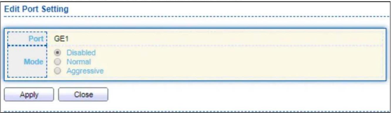
text_image
Edit Port Setting Port GE1 Mode Disabled Normal Aggressive Apply CloseFigure 154 - Diagnoscs > UDLD>Property>Edit
| Item | Descripon |
| Port | Display selected port to be edited. |
| Mode | Select UDLD running mode of interface.● Disabled: Disable UDLD funcon.● Normal: Running on normal mode that port goes to Link Up One phase aer last neighbor ages out.● Aggressive: Running on aggressive mode that port goes to Re-Establish phase aer last neighbor ages out. |
IV-13-7-2 Neighbor
To display Neighbor page, click Diagnoscs > UDLD > Neighbor
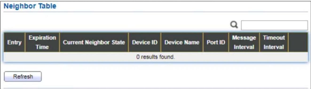
text_image
Neighbor Table Entry Expiration Time Current Neighbor State Device ID Device Name Port ID Message Interval Timeout Interval 0 results found. RefreshFigure 155 - Diagnoscs > UDLD>Neighbor
| Item | Descripon |
| Entry | Display entry index. |
| Expiraon Time | Display expiraon me before age out. |
| Current Neighbor State | Display neighbor current state. |
| Device ID | Display neighbor device ID. |
| Device Name | Display neighbor device name. |
| Port ID | Display neighbor port ID that connected. |
| Message Interval | Display neighbor message interval. |
| Timeout Interval | Display neighbor meout interval. |
IV-14 Management
Use the Management pages to congregate sengs for the switch management features.
IV-14-1 User Account
The default username/password is admin/admin. And default account is not able to be deleted.
Use this page to add additional users that are permied to manage the switch or to change the passwords of exisng users.
To display User Account web page, click Management > User Account.
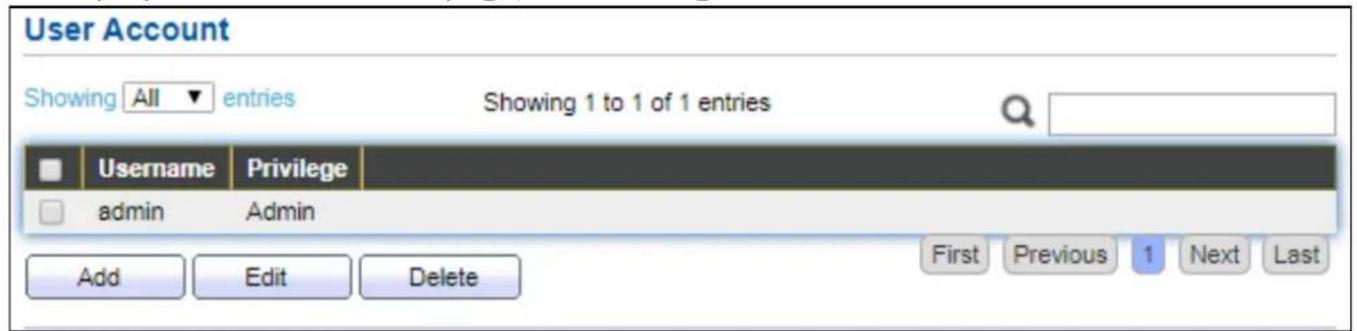
text_image
User Account Showing All entries Showing 1 to 1 of 1 entries Username Privilege admin Admin Add Edit Delete First Previous 1 Next LastFigure 156 - Management > User Account
| Item | Descripon |
| Username | User name of the account. |
| Privilege | Select privilege level for new account. Admin: Allow to change switch sengs. Privilege value equals to 15. User: See switch sengs only. Not allow to change it. Privilege level equals to 1. |
Click "Add" or "Edit" buon to view the Add/Edit User Account menu.
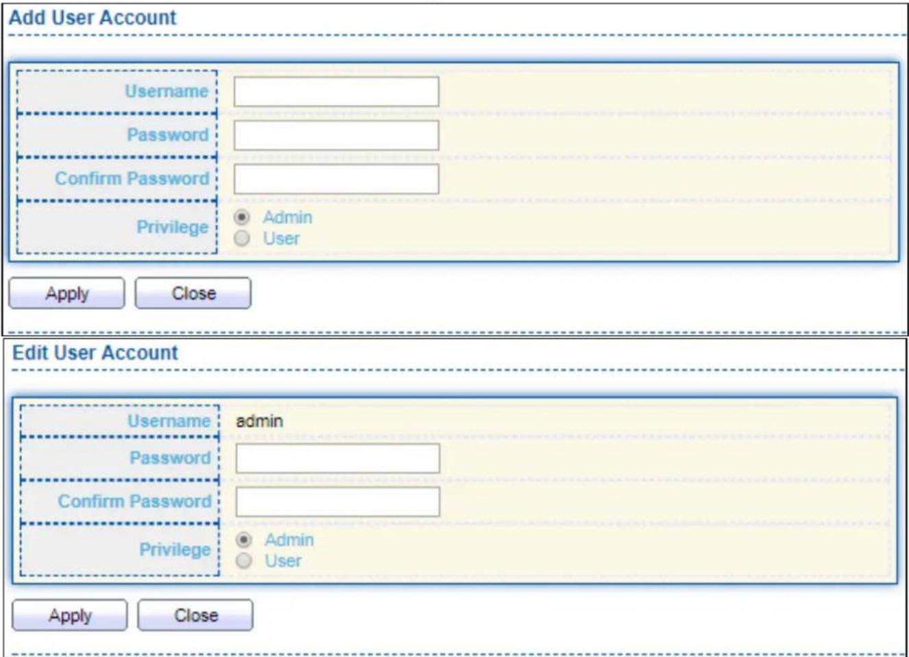
text_image
Add User Account Username Password Confirm Password Privilege Admin User Apply Close Edit User Account Username admin Password Confirm Password Privilege Admin User Apply CloseFigure 157 - Management > User Account > Add/Edit User Account
| Item | Descripon |
| Username | User name of the account. |
| Password | Set password of the account. |
| Conrm Password | Set the same password of the account as in “Password” eld. |
| Privilege | Select privilege level for new account.● Admin: Allow to change switch sengs. Privilege value equals to 15.● User: See switch sengs only. Not allow to change it. Privilege level equals to 1. |
IV-14-2 Fireware
IV-14-2-1 Upgrade / Backup
This page allows user to upgrade or backup rmware image through HTTP or TFTP server.
For Upgrade acon and HTTP method:
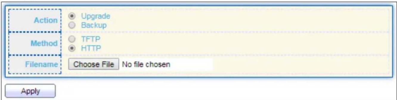
text_image
Action Upgrade Backup Method TFTP HTTP Filename Choose File No file chosen ApplyFigure 158 - Management > Firmware > Upgrade (Default Method: HTTP)
| Item | Descripon |
| Acon | Firmware operaonsUpgrade: Upgrade rmware from remote host to DUT.Backup: Backup rmware image from DUT to remote host. |
| Method | Firmware upgrade / backup method.TFTP: Using TFTP to upgrade/backup rmware.HTTP: Using WEB browser to upgrade/backup rmware. |
| Filename | Use browser to upgrade rmware, you should select rmware image le on your host PC. |
For Upgrade acon and TFTP method:
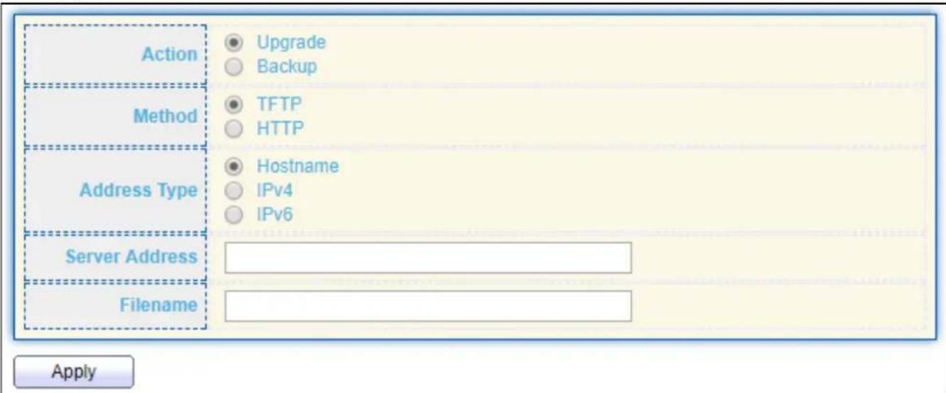
text_image
Action Upgrade Backup Method TFTP HTTP Address Type Hostname IPv4 IPv6 Server Address Filename ApplyFigure 159 - Management > Firmware > Upgrade (Method: TFTP)
| Item | Descripon |
| Acon | Firmware operaonsUpgrade: Upgrade rmware from remote host to DUTBackup: Backup rmware image from DUT to remote host |
| Method | Firmware upgrade / backup methodTFTP: Using TFTP to upgrade/backup rmware.HTTP: Using WEB browser to upgrade/backup rmware. |
| Address Type | Specify TFTP server address typeHostname: Use domain name as server addressIPv4: Use IPv4 as server addressIPv6: Use IPv6 as server address |
| Server Address | Specify TFTP server address. |
| Filename | Firmware image le name on remote TFTP server |
For Backup acon and HTTP method:

text_image
Action Upgrade Backup Method TFTP HTTP Firmware Image0 Image1 ApplyFigure 160 - Management > Firmware > Backup (Method: HTTP)
| Item | Descripon |
| Acon | Firmware operaonsUpgrade: Upgrade rmware from remote host to DUTBackup: Backup rmware image from DUT to remote host |
| Method | Firmware upgrade / backup methodTFTP: Using TFTP to upgrade/backup rmware.HTTP: Using WEB browser to upgrade/backup rmware. |
| Firmware | Firmware paron need to backupImage0: Firmware image in ash paron 0Image1: Firmware image in ash paron 1 |
For Backup acon and TFTP method:
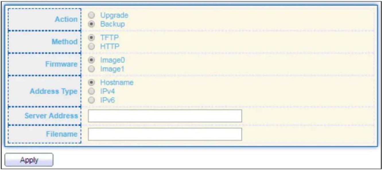
text_image
Action Upgrade Backup Method TFTP HTTP Firmware Image0 Image1 Address Type Hostname IPv4 IPv6 Server Address Filename ApplyFigure 161 - Management > Firmware > Backup (Method: TFTP)
| Item | Descripon |
| Acon | Firmware operaonsUpgrade: Upgrade rmware from remote host to DUTBackup: Backup rmware image from DUT to remote host |
| Method | Firmware upgrade / backup methodTFTP: Using TFTP to upgrade/backup rmware.HTTP: Using WEB browser to upgrade/backup rmware. |
| Firmware | Firmware paron need to backupImage0: Firmware image in ash paron 0.Image1: Firmware image in ash paron 1. |
| Address Type | Specify TFTP server address typeHostname: Use domain name as server address.IPv4: Use IPv4 as server address.IPv6: Use IPv6 as server address. |
| Server Address | Specify TFTP server address address. |
| Filename | File name saved on remote TFTP server. |
IV-14-2-2 Acve Image
This page allows user to select rmware image on next boong and show rmware informaon on both ash parons.
To display the Acve Image web page, click Management > Firmware > Acve Image.
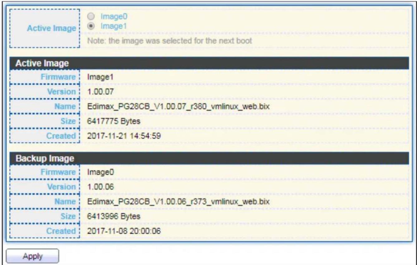
text_image
Active Image Image0 Image1 Note: the image was selected for the next boot Active Image Firmware Image1 Version 1.00.07 Name Edimax_PG28CB_V1.00.07_r380_vmlinux_web.bix Size 6417775 Bytes Created 2017-11-21 14:54:59 Backup Image Firmware Image0 Version 1.00.06 Name Edimax_PG28CB_V1.00.06_r373_vmlinux_web.bix Size 6413996 Bytes Created 2017-11-08 20:00:06 ApplyFigure 162 - Management > Firmware > Acve Image
| Item | Descripon |
| Acve Image | Select rmware image to use on next boong |
| Firmware | Firmware ash paron name. |
| Version | Firmware version. |
| Name | Firmware name. |
| Size | Firmware image size. |
| Created | Firmware image created date. |
IV-14-3 Conguraon
IV-14-3-1 Upgrade / Backup
This page allows user to upgrade or backup conguraon le through HTTP or TFTP server.
For Upgrade acon and HTTP method:
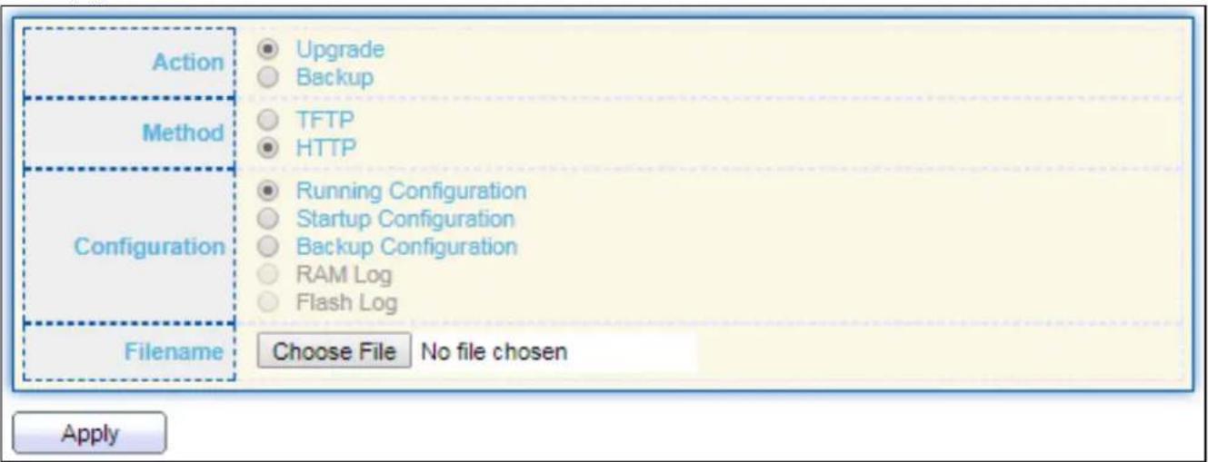
text_image
Action Upgrade Backup Method TFTP HTTP Configuration Running Configuration Startup Configuration Backup Configuration RAM Log Flash Log Filename Choose File No file chosen ApplyFigure 163 - Management > Conguraon > Upgrade (Default Method: HTTP)
| Item | Descripon |
| Acon | Conguraon operaonsUpgrade: Upgrade rmware from remote host to DUTBackup: Backup rmware image from DUT to remote host |
| Method | Conguraon upgrade / backup methodTFTP: Using TFTP to upgrade/backup rmwareHTTP: Using WEB browser to upgrade/backup rmware |
| Conguraon | Conguraon typesRunning Conguraon: Merge to current running conguraon leStartup Conguraon: Replace startup conguraon leBackup Conguraon: Replace backup conguraon le |
| Filename | Use browser to upgrade conguraon, you should select conguraon le on your host PC. |
For Upgrade acon and TFTP method:

text_image
Action Upgrade Backup Method TFTP HTTP Configuration Running Configuration Startup Configuration Backup Configuration RAM Log Flash Log Address Type Hostname IPv4 IPv6 Server Address Filename ApplyFigure 164 - Management > Conguraon > Upgrade (Method: TFTP)
| Item | Descripon |
| Acon | Conguraon operaonsUpgrade: Upgrade rmware from remote host to DUTBackup: Backup rmware image from DUT to remote host |
| Method | Conguraon upgrade / backup methodTFTP: Using TFTP to upgrade/backup rmwareHTTP: Using WEB browser to upgrade/backup rmware |
| Conguraon | Conguraon typesRunning Conguraon: Merge to current running conguraon leStartup Conguraon: Replace startup conguraon leBackup Conguraon: Replace backup conguraon le |
| Address Type | Specify TFTP server address typeHostname: Use domain name as server addressIPv4: Use IPv4 as server addressIPv6: Use IPv6 as server address |
| Server Address | Specify TFTP server address address |
| Filename | File name saved on remote TFTP server |
To display rmware upgrade or backup web page, click Management > Conguraon > Upgrade/Backup.
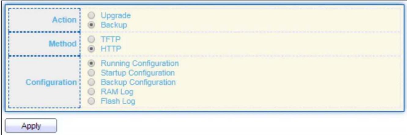
text_image
Action Upgrade Backup Method TFTP HTTP Configuration Running Configuration Startup Configuration Backup Configuration RAM Log Flash Log ApplyFigure 165 - Management > Conguraon > Upgrade/Backup
| Item | Descripon |
| Acon | Conguraon operaonsUpgrade: Upgrade rmware from remote host to DUTBackup: Backup rmware image from DUT to remote host |
| Method | Conguraon upgrade / backup methodTFTP: Using TFTP to upgrade/backup rmwareHTTP: Using WEB browser to upgrade/backup rmware |
| Conguraon | Conguraon typesRunning Conguraon: Backup running conguraon le.Startup Conguraon: Backup start conguraon le.Backup Conguraon: Backup backup conguraon le.RAM Log: Backup log le stored in RAM.Flash Log: Backup log les store in Flash. |
For Backup acon and TFTP method:

text_image
Action Method Configuration Address Type Server Address Filename Upgrade Backup TFTP HTTP Running Configuration Startup Configuration Backup Configuration RAM Log Flash Log Hostname IPv4 IPv6 ApplyFigure 166 - Management > Conguraon > Backup (Method: TFTP)
| Item | Descripon |
| Acon | Conguraon operaonsUpgrade: Upgrade rmware from remote host to DUTBackup: Backup rmware image from DUT to remote host |
| Method | Conguraon upgrade / backup methodTFTP: Using TFTP to upgrade/backup rmwareHTTP: Using WEB browser to upgrade/backup rmware |
| Conguraon | Conguraon typesRunning Conguraon: Backup running conguraon le.Startup Conguraon: Backup start conguraon le.Backup Conguraon: Backup backup conguraon le.RAM Log: Backup log le stored in RAM.Flash Log: Backup log les store in Flash. |
| Address Type | Specify TFTP server address typeHostname: Use domain name as server addressIPv4: Use IPv4 as server addressIPv6: Use IPv6 as server address |
| Server Address | Specify TFTP server address address. |
| Filename | File name saved on remote TFTP server. |
IV-14-3-2 Save Conguraon
This page allows user to manage conguraon le saved on DUT and click "Restore Factory Default" buon to restore factory defaults.
To display the Save Conguraon web page, click Management > Conguraon > Save Conguraon.

text_image
Source File Running Configuration Startup Configuration Backup Configuration Destination File Startup Configuration Backup Configuration Apply Restore Factory DefaultFigure 167 - Management > Conguraon > Save Conguraon
| Item | Descripon |
| Source File | Source le types● Running Conguraon: Copy running conguraon le to desnaon.● Startup Conguraon: Copy startup conguraon le to desnaon.● Backup Conguraon: Copy backup conguraon le to desnaon |
| Desnaon File | Desnaon le● Startup Conguraon: Save le as startup conguraon.● Backup Conguraon: Save le as backup conguraon. |
IV-14-4 SNMP
IV-14-4-1 View
To congure and display the SNMP view table, click Management > SNMP > View.
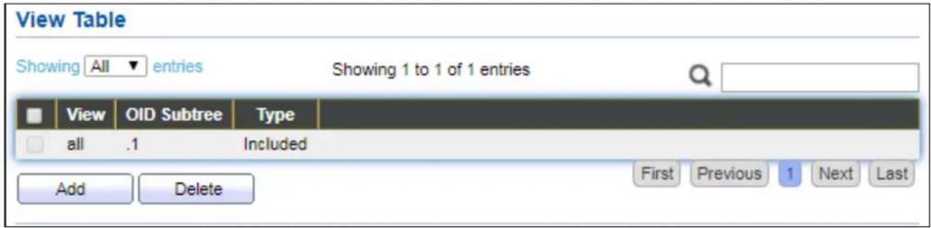
text_image
View Table Showing All entries Showing 1 to 1 of 1 entries View OID Subtree Type all .1 Included Add Delete First Previous 1 Next LastFigure 168 - Management > SNMP > View
| Item | Descripon |
| View | The SNMP view name. Its maximum length is 30 characters |
| OID Subtree | Specify the ASN.1 subtree object idener (OID) to be included or excluded from the SNMP view |
| Type | Include or exclude the selected MIBs in the view |
IV-14-4-2 Group
To congure and display the SNMP group sengs, click Management > SNMP > Group.

text_image
Group Table Showing All entries Showing 0 to 0 of 0 entries Group Version Security Level View Read Write Notify 0 results found. First Previous 1 Next Last Configure SNMP View to associate a non-default view with a group. Add Edit DeleteFigure 169 - Management > SNMP > Group
| Item | Descripon |
| Group | Specify SNMP group name, and the maximum length is 30 characters. |
| Version | Specify SNMP version● SNMPv1: SNMP Version 1.● SNMPv2: Community-based SNMP Version 2.● SNMPv3: User security model SNMP version 3. |
| Security Level | Specify SNMP security level● No Security: Specify that no packet authencaon is performed.● Authencaon: Specify that no packet authencaon without encrypon is performed.● Authencaon and Privacy: Specify that no packet authencaon with encrypon is performed. |
| View | |
| Read | Group read view name. |
| Write | Group write view name. |
| Nofy | The view name that sends only traps with contents that is included in SNMP view selected for nocaon. |
Click "Add" or "Edit" buon to view the Add/Edit Group menu.
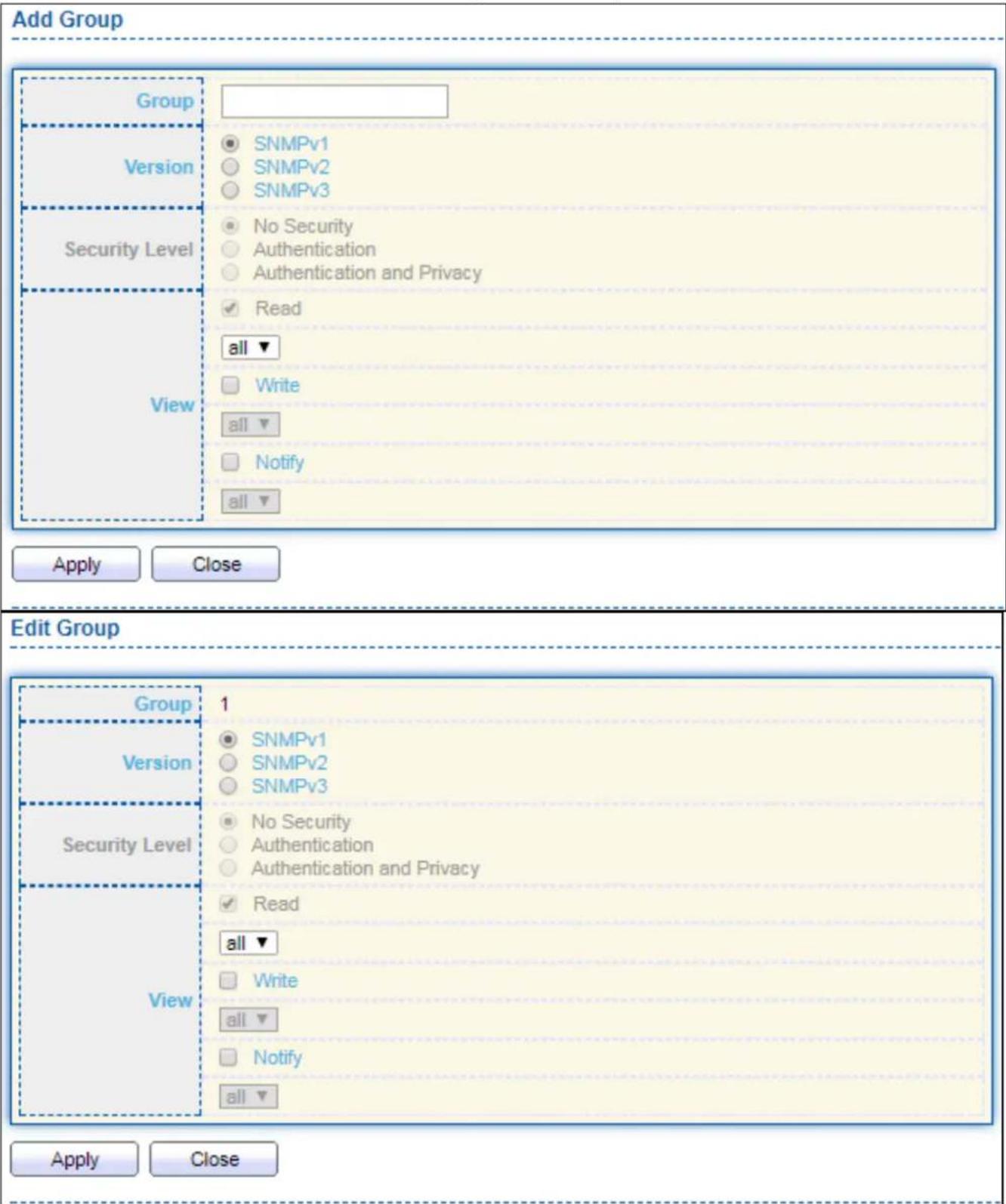
text_image
Add Group Group Version Security Level View SNMPv1 SNMPv2 SNMPv3 No Security Authentication Authentication and Privacy Read all ▼ Write all ▼ Notify all ▼ Apply Close Edit Group Group 1 Version SNMPv1 SNMPv2 SNMPv3 Security Level No Security Authentication Authentication and Privacy Read all ▼ Write all ▼ Notify all ▼ Apply CloseFigure 170 - Management > SNMP > Group > Add/Edit Group
| Item | Descripon |
| Group | Specify SNMP group name, and the maximum length is 30 characters. |
| Version | Spedify SNMP version● SNMPv1: SNMP Version 1.● SNMPv2: Community-based SNMP Version 2.● SNMPv3: User security model SNMP version 3. |
| Security Level | Specify SNMP security level● No Security : Specify that no packet authencaon is performed.● Authencaon: Specify that no packet authencaon without encrypon is performed.● Authencaon and Privacy: Specify that no packet authencaon with encrypon is performed. |
| View | |
| Read | Select read view name if Read is checked. |
| Write | Select write view name, if Write is checked. |
| Nofy | Select nofy view name, if Nofy is checked. |
IV-14-4-3 Community
To congure and display the SNMP community sengs, click Management > SNMP > Community.
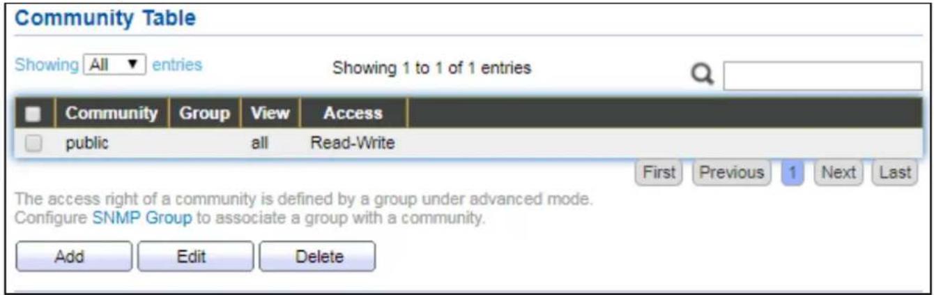
text_image
Community Table Showing All entries Showing 1 to 1 of 1 entries Community Group View Access public all Read-Write First Previous 1 Next Last The access right of a community is defined by a group under advanced mode. Configure SNMP Group to associate a group with a community. Add Edit DeleteFigure 171 - Management > SNMP > Community
| Item | Descripon |
| Community | The SNMP community name. Its maximum length is 20 characters. |
| Group | Specify the SNMP group congured by the command snmp group to dene the object available to the community. |
| View | Specify the SNMP view to dene the object available to the community. |
| Access | SNMP access mode● Read-Only: Read only.● Read-Write: Read and write. |
Click "Add" or "Edit" buon to view the Add/Edit Community menu.
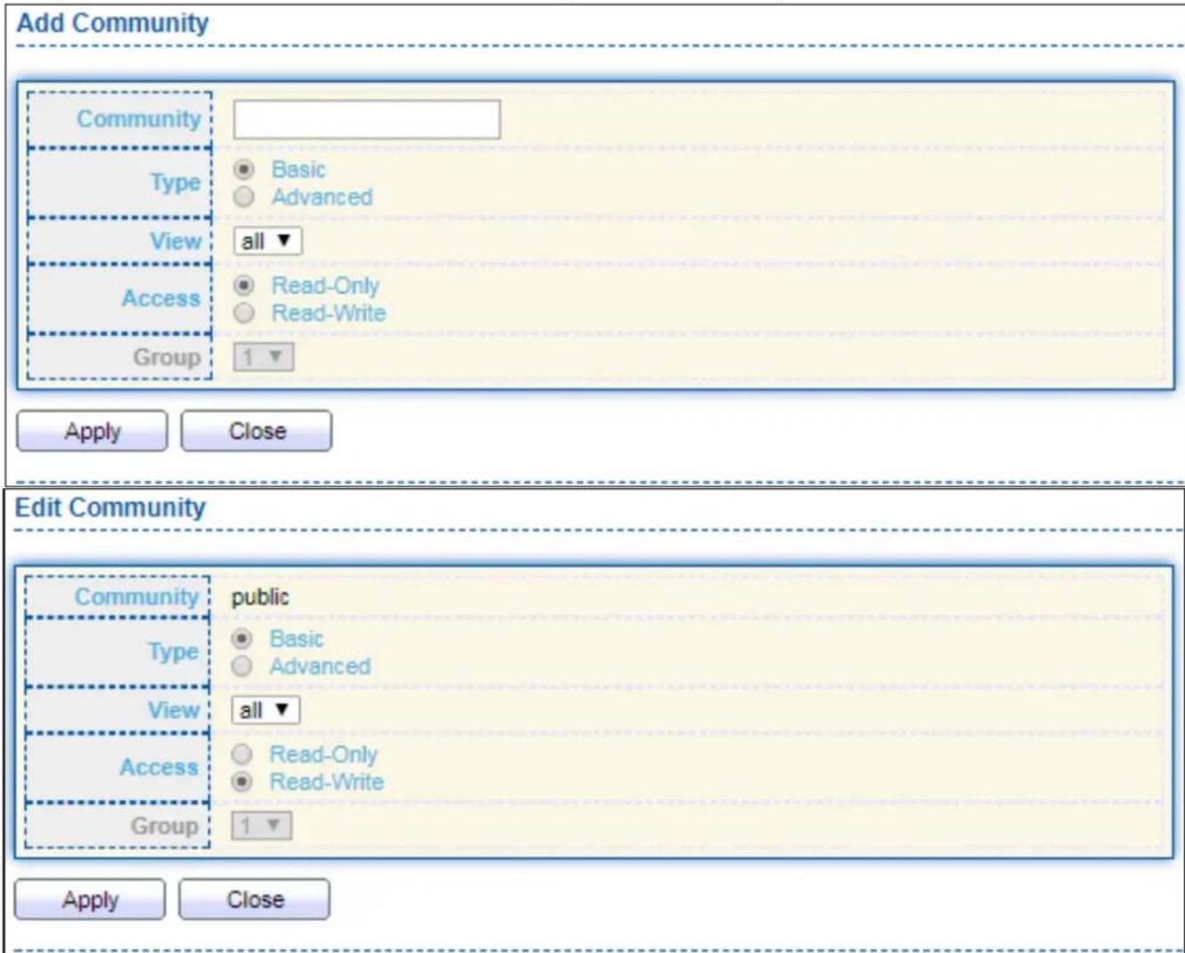
text_image
Add Community Community Type Basic Advanced View all ▼ Access Read-Only Read-Write Group 1 ▼ Apply Close Edit Community Community public Type Basic Advanced View all ▼ Access Read-Only Read-Write Group 1 ▼ Apply CloseFigure 172 - Management > SNMP > Group > Add/Edit Community
| Item | Descripon |
| Community | The SNMP community name. Its maximum length is 20 characters. |
| Type | SNMP Community mode● Basic: SNMP community species view and access right.● Advanced: SNMP community species group. |
| View | Specify the SNMP view to dene the object available to the community. |
| Access | SNMP access mode● Read-Only: Read only.● Read-Write: Read and write. |
| Group | Specify the SNMP group congured by the command snmp group to dene the object available to the community. |
IV-14-4-4 User
To congure and display the SNMP users, click Management > SNMP > User.

text_image
User Table Showing All entries Showing 0 to 0 of 0 entries User Group Security Level Authentication Method Privacy Method 0 results found. Configure SNMP Group to associate an SNMPv3 group with an SNMPv3 user. Add Edit Delete First Previous 1 Next LastFigure 173 - Management > SNMP > User
| Item | Descripon |
| User | Specify the SNMP user name on the host that connects to the SNMP agent. The max character is 30 characters. For the SNMP v1 or v2c, the user name must match the community name. |
| Group | Specify the SNMP group to which the SNMP user belongs. |
| Security Level | SNMP privilege modeNo Security: Specify that no packet authencaon is performed.Authencaon: Specify that no packet authencaon without encrypon is performed.Authencaon and Privacy: Specify that no packet authencaon with encrypon is performed. |
| Authencaon Method | Authencaon Protocol which is available when Privilege Mode is Authencaon or Authencaon and Privacy.None: No authencaon required.MD5: Specify the HMAC-MD5-96 authencaon protocol.SHA: Specify the HMAC-SHA-96 authencaon protocol |
| Privacy Method | Encrypon ProtocolNone: No privacy required.DES: DES algorithm |
Click "Add" or "Edit" buon to view Add/Edit User menu.

text_image
Add User User Group 11 ▼ Security Level No Security Authentication Authentication and Privacy Method None MD5 SHA Password Privacy Method None DES Password Apply Close Edit User User 22 Group 11 ▼ Security Level No Security Authentication Authentication and Privacy Authentication Method None MD5 SHA Password Privacy Method None DES Password Apply CloseFigure 174 - Management > SNMP > User > Add/Edit User
| Item | Descripon |
| User | Specify the SNMP user name on the host that connects to the SNMP agent. The max character is 30 characters. |
| Group | Specify the SNMP group to which the SNMP user belongs. |
| Security Level | SNMP privilege modeNo Security: Specify that no packet authencaon is performed.Authencaon: Specify that no packet authencaon without encrypon is performed.Authencaon and Privacy: Specify that no packet authencaon with encrypon is performed. |
| Authencaon | |
| Method | Authencaon Protocol which is available when Privilege Mode is Authencaon or Authencaon and Privacy.None: No authencaon required.MD5: Specify the HMAC-MD5-96 authencaon protocol.SHA: Specify the HMAC-SHA-96 authencaon protocol. |
| Password | The authencaon password, The number of character range is 8 to 32 characters. |
| Privacy | |
| Method | Encrypon ProtocolNone: No privacy required.DES: DES algorithm |
| Password | The privacy password, The number of character range is 8 to 64 characters. |
IV-14-4-5 Engine ID
To congure and display SNMP local and remote engine ID, click Management > SNMP > Engine ID.
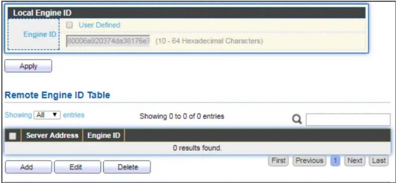
text_image
Local Engine ID Engine ID User Defined 80006a920374da38176e7 (10 - 64 Hexadecimal Characters) Apply Remote Engine ID Table Showing All entries Showing 0 to 0 of 0 entries Server Address Engine ID 0 results found. Add Edit Delete First Previous 1 Next LastFigure 175 - Management > SNMP > Engine ID
| Item | Descripon |
| Local Engine ID | |
| Engine ID | If checked “User Dened”, the local engine ID is congure by user, else use the default Engine ID which is made up of MAC and Enterprise ID.The user dened engine ID is range 10 to 64 hexadecimal characters, and the hexadecimal number must be divided by 2. |
| Remote Engine ID TableTable | |
| Server Address | Remote host. |
| Engine ID | Specify Remote SNMP engine ID. The engine ID is range10 to 64 hexadecimal characters, and the hexadecimal number must be divided by 2. |
Click "Add" buon to view Add Remote Engine ID menu.
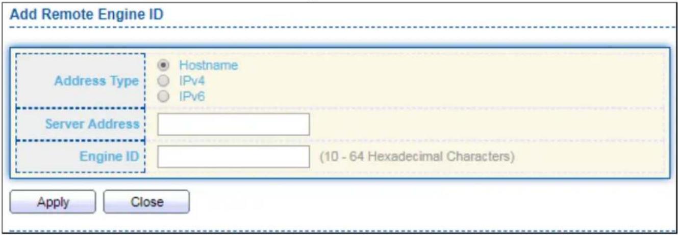
text_image
Add Remote Engine ID Address Type Hostname IPv4 IPv6 Server Address Engine ID (10 - 64 Hexadecimal Characters) Apply CloseFigure 176 - Management > SNMP > Add Engine ID
| Item | Descripon |
| Address Type | Remote host address type for Hostname/IPv4/IPv6. |
| Server Address | Remote host. |
| Engine ID | Specify Remote SNMP engine ID. The engine ID is range10 to 64 hexadecimal characters, and the hexadecimal number must be divided by 2. |
Click "Edit" buon to view Edit Remote Engine ID menu.
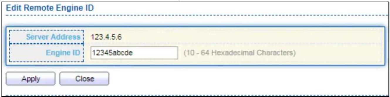
text_image
Edit Remote Engine ID Server Address 123.4.5.6 Engine ID 12345abcde (10 - 64 Hexadecimal Characters) Apply CloseFigure 177 - Management > SNMP > Edit Engine ID
| Item | Descripon |
| Server Address | Edit Remote host address |
| Engine ID | Specify Remote SNMP engine ID. The engine ID is range10 to 64 hexadecimal characters, and the hexadecimal number must be divided by 2. |
IV-14-4-6 Trap Event
To congure and display SNMP trap event, click Management > SNMP > Trap Event.
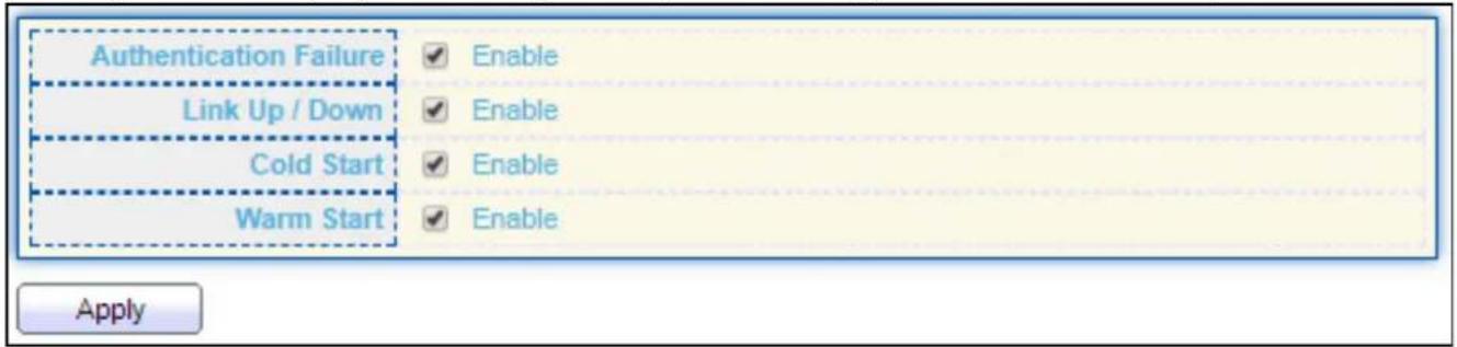
text_image
Authentication Failure Link Up / Down Cold Start Warm Start Enable Enable Enable Enable ApplyFigure 178 - Management > SNMP > Trap Event
| Item | Descripon |
| AuthencaonFailure | SNMP authencaon failure trap, when community not match or user authencaon password not match. |
| Link Up/Down | Port link up or down trap. |
| Cold Start | Device reboot congure by user trap. |
| Warm Start | Device reboot by power down trap. |
IV-14-4-7 Nocaon
To congure the hosts to receive SNMPv1/v2/v3 nocaaon, click Management > SNMP > Nocaaon.
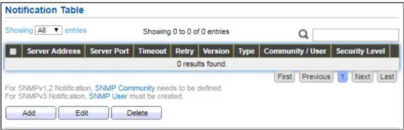
text_image
Notification Table Showing All entries Showing 0 to 0 of 0 entries Server Address Server Port Timeout Retry Version Type Community / User Security Level 0 results found. First Previous 1 Next Last For SNMPv1,2 Notification, SNMP Community needs to be defined. For SNMPv3 Notification, SNMP User must be created. Add Edit DeleteFigure 179 - Management > SNMP > Nocaon
| Item | Descripon |
| Server Address | IP address or the hostname of the SNMP trap recipients. |
| Server Port | Recipients server UDP port number. |
| Timeout | Specify the SNMP informs meout. |
| Retry | Specify the retry counter of the SNMP informs. |
| Version | Specify SNMP nocaon version● SNMPv1: SNMP Version 1 nocaon.● SNMPv2: SNMP Version 2 nocaon.● SNMPv3: SNMP Version 3 nocaon. |
| Type | Nocaon Type● Trap: Send SNMP traps to the host.● Inform: Send SNMP informs to the host. |
| Community/User | SNMP community/user name for nocaon. If version is SNMPv3 the name is user name, else is community name. |
| UDP Port | Specify the UDP port number. |
| Timeout | Specify the SNMP informs meout. |
| Security Level | SNMP trap packet security level● No Security: Specify that no packet authencaon is performed.● Authencaon: Specify that no packet authencaon without encrypon is performed.● Authencaon and Privacy: Specify that no packet authencaon with encrypon is performed. |
Click "Add" buon to view the Nocaon menu.
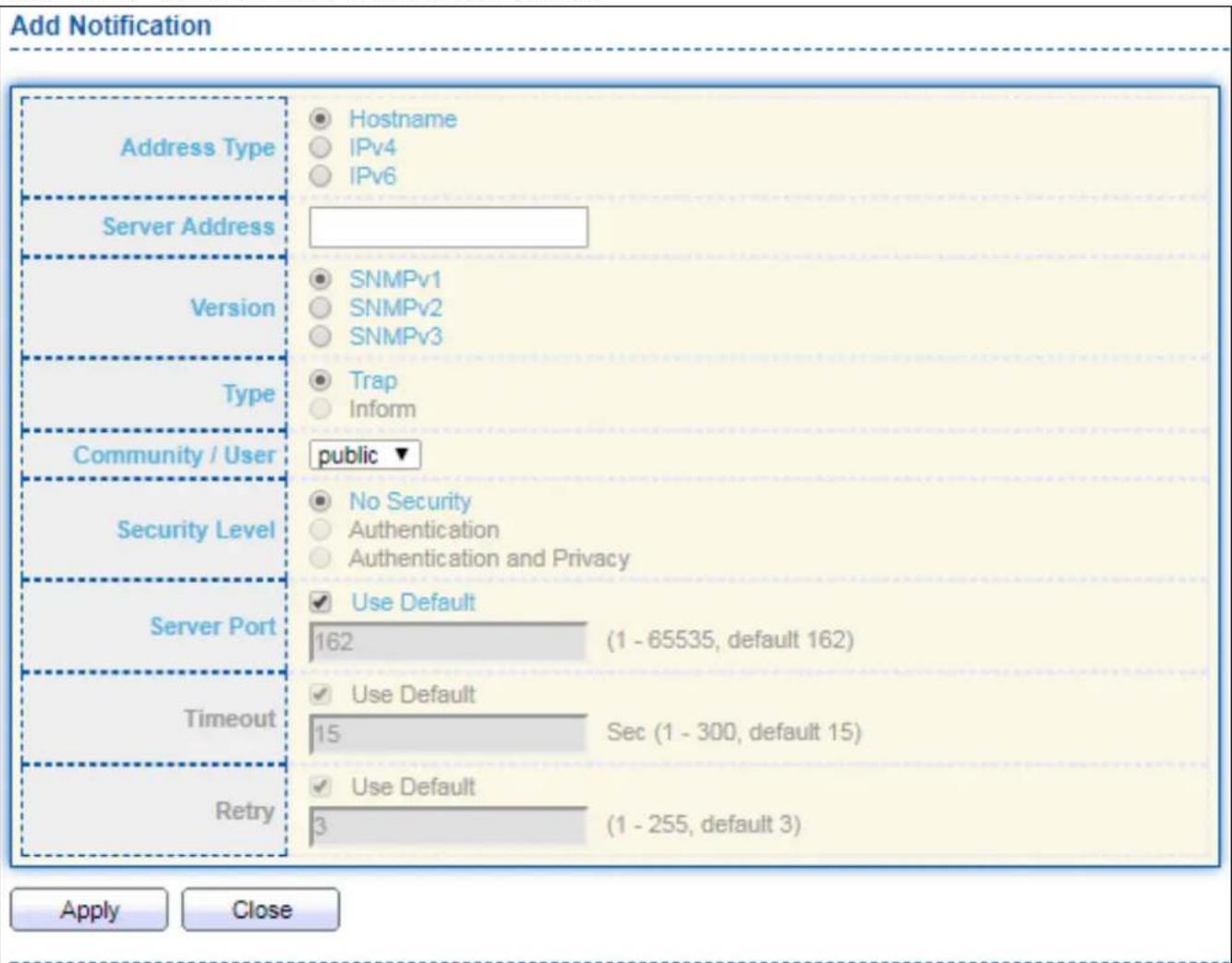
text_image
Add Notification Address Type Hostname IPv4 IPv6 Server Address SNMPv1 SNMPv2 SNMPv3 Version Type Trap Inform Community / User public ▼ Security Level No Security Authentication Authentication and Privacy Server Port Use Default 162 (1 - 65535, default 162) Timeout Use Default 15 Sec (1 - 300, default 15) Retry Use Default 3 (1 - 255, default 3) Apply CloseFigure 180 - Management > SNMP > Nocaon > Add Nocaon
| Item | Descripon |
| Address Type | Nofy recipients host address type. |
| Server Address | IP address or the hostname of the SNMP trap recipients. |
| Version | Specify SNMP nocaon version● SNMPv1: SNMP Version 1 nocaon.● SNMPv2: SNMP Version 2 nocaon.● SNMPv3: SNMP Version 3 nocaon. |
| Type | Nocaon Type● Trap: Send SNMP traps to the host.● Inform: Send SNMP informs to the host.(version 1 have no inform) |
| Community/User | SNMP community/user name for nocaon. If version is SNMPv3 the name is user name, else is community name. |
| Security Level | SNMP nocaon packet security level, the security level must less than or equal to the community/user name● No Security: Specify that no packet authencaon is performed.● Authencaon: Specify that no packet authencaon without encrypon is performed.● Authencaon and Privacy: Specify that no packet authencaon with encrypon is performed. |
| Server Port | Recipient server UDP port number, if “use default” checked the value is 162, else user congure. |
| Timeout | Specify the SNMP informs meout, if “use default” checked the value is 15, else user congure. |
| Retry | Specify the SNMP informs retry count, if “use default” checked the value is 3, else user congure. |
Click "Edit" buon to view the Edit Nocaon menu.

text_image
Edit Notification Server Address 123.4.5.6 Version SNMPv1 SNMPv2 SNMPv3 Type Trap Inform Community / User public ▼ Security Level No Security Authentication Authentication and Privacy Server Port Use Default 162 (1 - 65535, default 162) Timeout Use Default Sec (1 - 300, default 15) Retry Use Default 3 (1 - 255, default 3) Apply CloseFigure 181 - Management > SNMP > Nocaon > Edit Nocaon
| Item | Descripon |
| Server Address | Edit SNMP nofy recipients address |
| Version | Specify SNMP nocaon version● SNMPv1: SNMP Version 1 nocaon.● SNMPv2: SNMP Version 2 nocaon.● SNMPv3: SNMP Version 3 nocaon. |
| Type | Nocaon Type● Trap: Send SNMP traps to the host.● Inform: Send SNMP informs to the host.(version 1 have no inform) |
| Community/User | SNMP community/user name for nocaon. If version is SNMPv3 the name is user name, else is community name. |
| Community Level | SNMP nocaon packet security level, the security level must less than or equal to the community/user name● No Security: Specify that no packet authencaon is performed.● Authencaon: Specify that no packet authencaon without encrypon is performed.● Authencaon and Privacy: Specify that no packet authencaon with encrypon is performed. |
| Server Port | Recipients server UDP port number, if “use default” checked the valueis 162, else user congure. |
| Timeout | Specify the SNMP informs meout, if “use default” checked the value is 15, else user congure. |
| Retry | Specify the SNMP informs retry count, if “use default” checked the value is 3, else user congure. |
COPYRIGHT
Copyright © Edimax Technology Co., Ltd. all rights reserved. No part of this publicaon may be reproduced, transmied, transcribed, stored in a retrieval system, or translated into any language or computer language, in any form or by any means, electronic, mechanical, magnec, opcal, chemical, manual or otherwise, without the prior written permission from Edimax Technology Co., Ltd.
Edimax Technology Co., Ltd. makes no representaons or warranes, either expressed or implied, with respect to the contents hereof and specifically disclaims any warranes, merchantability, or tness for any parcular purpose. Any soware described in this manual is sold or licensed as is. Should the programs prove defecve following their purchase, the buyer (and not this company, its distributor, or its dealer) assumes the enre cost of all necessary servicing, repair, and any incidental or consequential damages resulting from any defect in the soware. Edimax Technology Co., Ltd. reserves the right to revise this publicaon and to make changes from me to me in the contents hereof without the obligaon to nofy any person of such revision or changes.
The product you have purchased and the setup screen may appear slightly dierent from those shown in this QIG. The soware and specicaons are subject to change without noce. Please visit our website www.edimax.com for updates. All brand and product names menoned in this manual are trademarks and/or registered trademarks of their respective holders.
Federal Communicaon Commission Interference Statement
This equipment has been tested and found to comply with the limits for a Class B digital device, pursuant to Part 15 of FCC Rules. These limits are designed to provide reasonable protecon against harmful interference in a residential installaon. This equipment generates, uses, and can radiate radio frequency energy and, if not installed and used in accordance with the instrucons, may cause harmful interference to radio communicaons. However, there is no guarantee that interference will not occur in a parcular installaon. If this equipment does cause harmful interference to radio or television recepon, which can be determined by turning the equipment o and on, the user is encouraged to try to correct the interference by one or more of the following measures:
- Reorient or relocate the receiving antenna.
- Increase the separaon between the equipment and receiver.
- Connect the equipment into an outlet on a circuit dierent from that to which the receiver is connected.
- Consult the dealer or an experienced radio technician for help.
FCC Cauon
This device and its antenna must not be co-located or operang in conjuncon with any other antenna or transmier. This device complies with Part 15 of the FCC Rules. Operaon is subject to the following two conditions: (1) this device may not cause harmful interference, and (2) this device must accept any interference received, including interference that may cause undesired operaon. Any changes or modicaons not expressly approved by the party responsible for compliance could void the authority to operate equipment.
Federal Communicaons Commission (FCC) Radiaon Exposure Statement
This equipment complies with FCC radiaon exposure set forth for an uncontrolled environment. In order to avoid the possibility of exceeding the FCC radio frequency exposure limits, human proximity to the antenna shall not be less than 2.5cm (1 inch) during normal operaon.
Federal Communicaons Commission (FCC) RF Exposure Requirements
This EUT is compliance with SAR for general population/uncontrolled exposure limits in ANSI/IEEE C95.1-1999 and had been tested in accordance with the measurement methods and procedures specified in OET Bullen 65 Supplement C. The equipment version marketed in US is restricted to usage of the channels 1-11 only. This equipment is restricted to indoor use when operated in the 5.15 to 5.25 GHz frequency range.
R&TTE Compliance Statement
This equipment complies with all the requirements of DIRECTIVE 2014/30/EU OF THE EUROPEAN PARLIAMENT AND THE COUNCIL of March 9, 1999 on radio equipment and telecommunicaon terminal equipment and the mutual recognition of their conformity (R&TTE). The R&TTE Directive repeals and replaces in the directive 98/13/EEC (Telecommunicaons Terminal Equipment and Satellite Earth Staon Equipment) As of April 8, 2000.
Safety
This equipment is designed with the utmost care for the safety of those who install and use it. However, special aenon must be paid to the dangers of electric shock and stac electricity when working with electrical equipment. All guidelines of this and of the computer manufacture must therefore be allowed at all mes to ensure the safe use of the equipment.
EU Countries Intended for Use
The ETSI version of this device is intended for home and oce use in Austria, Belgium, Bulgaria, Cyprus, Czech, Denmark, Estonia, Finland, France, Germany, Greece, Hungary, Ireland, Italy, Latvia, Lithuania, Luxembourg, Malta, Netherlands, Poland, Portugal, Romania, Slovakia, Slovenia, Spain, Sweden, Turkey, and United Kingdom. The ETSI version of this device is also authorized for use in EFTA member states: Iceland, Liechtenstein, Norway, and Switzerland.
EU Countries Not Intended for Use
None
EU Declaraon of Conformity
English: This equipment is in compliance with the essenal requirements and other relevant provisions of Direcve 2014/30/EU.
WEEE Directive & Product Disposal

At the end of its serviceable life, this product should not be treated as household or general waste. It should be handed over to the applicable collecon point for the recycling of electrical and electronic equipment, or returned to the supplier for disposal.
Declaraon of Conformity
We, Edimax Technology Co., Ltd., declare under our sole responsibility, that the equipment described below complies with the requirements of the European R&TTE directives.
Equipment: 16-port GbE Switch + 4 Combo GbE Ports with 16 PoE ports Model No.: GS-5416PLC
The following European standards for essenal requirements have been followed:
Directives 2014/30/EU
EMC : EN 55032:2015
EN 61000-3-2:2014 Class A
EN 61000-3-3:2013
EN 55024:2015
Safety (LVD) : EN 60950-1:2006 + A11:2009 + A1:2010 + A12:2011+A2:2013
Edimax Technology Europe B.V.
a company of:
Fijenhof 2,
Edimax Technology Co., Ltd.
5652 AE Eindhoven,
No. 278, Xinhu 1st Rd.,
The Netherlands
Neihu Dist., Taipei City,
Printed Name: David Huang
Taiwan
Title: Director
Edimax Technology Europe B.V.

Date of Signature: April, 2018
Signature:

Printed Name:
Albert Chang
Title:
Director
Edimax Technology Co., Ltd.
Declaraon of Conformity
We, Edimax Technology Co., Ltd., declare under our sole responsibility, that the equipment described below complies with the requirements of the European R&TTE directives.
Equipment: 24-port GbE Switch+4 Combo Ports with 24 PoE ports
Model No.: GS-5424PLC
The following European standards for essenal requirements have been followed:
Direcves 2014/30/EU
EMC : EN 55032:2015+AC:2016
EN 61000-3-2:2014
EN 61000-3-3:2013
EN 55035:2017
Direcves 2014/35/EU
Safety (LVD) : IEC 62368-1:2014 (2nd Edion) and/or EN 62368-1:2014+A11:2017
Edimax Technology Europe B.V.
Fijenhof 2,
5652 AE Eindhoven,
The Netherlands
a company of:
Edimax Technology Co., Ltd.
No. 278, Xinhu 1st Rd.,
Neihu Dist., Taipei City,
Taiwan
Printed Name: David Huang
Title: Director
Edimax Technology Europe B.V.

Date of Signature: Nov., 2020
Signature:

Printed Name:
Albert Chang
Title:
Director
Edimax Technology Co., Ltd.
Noce According to GNU General Public License Version 2
This product includes soware that is subject to the GNU General Public License version 2. The program is free soware and distributed without any warranty of the author. We oer, valid for at least three years, to give you, for a charge no more than the costs of physically performing source distribuon, a complete machine-readable copy of the corresponding source code.
Version 2, June 1991
Copyright (C) 1989, 1991 Free Soware Foundaon, Inc. 51 Franklin Street, Fih Floor, Boston, MA 02110-1301, USA Everyone is permitted to copy and distribute verbam copies of this license document, but changing it is not allowed.
Preamble
The licenses for most soware are designed to take away your freedom to share and change it. By contrast, the GNU General Public License is intended to guarantee your freedom to share and change free soware--to make sure the soware is free for all its users. This General Public License applies to most of the Free Soware Foundaon's soware and to any other program whose authors commit to using it. (Some other Free Soware Foundaon soware is covered by the GNU Lesser General Public License instead.) You can apply it to your programs, too.
When we speak of free soware, we are referring to freedom, not price. Our General Public Licenses are designed to make sure that you have the freedom to distribute copies of free soware (and charge for this service if you wish), that you receive source code or can get it if you want it, that you can change the soware or use pieces of it in new free programs; and that you know you can do these things.
To protect your rights, we need to make restricons that forbid anyone to deny you these rights or to ask you to surrender the rights. These restricons translate to certain responsibilities for you if you distribute copies of the soware, or if you modify it.
For example, if you distribute copies of such a program, whether gras or for a fee, you must give the recipients all the rights that you have. You must make sure that they, too, receive or can get the source code. And you must show them these terms so they know their rights.
We protect your rights with two steps: (1) copyright the soware, and (2) oer you this license which gives you legal permission to copy, distribute and/or modify the soware.
Also, for each author's protecon and ours, we want to make certain that everyone understands that there is no warranty for this free soware. If the soware is modified by someone else and passed on, we want its recipients to know that what they have is not the original, so that any problems introduced by others will not react on the original authors' reputaons.
Finally, any free program is threatened constantly by soware patents. We wish to avoid the danger that redistributors of a free program will individually obtain patent licenses, in eect making the program proprietary. To prevent this, we have made it clear that any patent must be licensed for everyone's free use or not licensed at all.
The precise terms and conditions for copying, distribuon and modicaon follow.
TERMS AND CONDITIONS FOR COPYING, DISTRIBUTION AND MODIFICATION
- This License applies to any program or other work which contains a noce placed by the copyright holder saying it may be distributed under the terms of this General Public License. The “Program”, below, refers to any such program or work, and a “work based on the Program” means either the Program or any derivative work under copyright law: that is to say, a work containing the Program or a poron of it, either verbam or with modicaons and/or translated into another language. (Hereinaer, translaon is included without limitaon in the term “modicaon”.) Each licensee is addressed as “you”.
Acvies other than copying, distribuon and modicaon are not covered by this License; they are outside its scope. The act of running the Program is not restricted, and the output from the Program is covered only if its contents constute a work based on the Program (independent of having been made by running the Program). Whether that is true depends on what the Program does.
- You may copy and distribute verbam copies of the Program's source code as you receive it, in any medium, provided that you conspicuously and appropriately publish on each copy an appropriate copyright noce and disclaimer of warranty; keep
intact all the noces that refer to this License and to the absence of any warranty; and give any other recipients of the Program a copy of this License along with the Program.
You may charge a fee for the physical act of transferring a copy, and you may at your opon oer warranty protecon in exchange for a fee.
- You may modify your copy or copies of the Program or any poron of it, thus forming a work based on the Program, and copy and distribute such modicaons or work under the terms of Secon 1 above, provided that you also meet all of these conditions:
a) You must cause the modified les to carry prominent noces stang that you changed the les and the date of any change.
b) You must cause any work that you distribute or publish, that in whole or in part contains or is derived from the Program or any part thereof, to be licensed as a whole at no charge to all third pares under the terms of this License.
c) If the modified program normally reads commands interactively when run, you must cause it, when started running for such interactive use in the most ordinary way, to print or display an announcement including an appropriate copyright notice and a notice that there is no warranty (or else, saying that you provide a warranty) and that users may redistribute the program under these conditions, and telling the user how to view a copy of this License. (Excepon: if the Program itself is interactive but does not normally print such an announcement, your work based on the Program is not required to print an announcement.)
These requirements apply to the modified work as a whole. If idenable seconds of that work are not derived from the Program, and can be reasonably considered independent and separate works in themselves, then this License, and its terms, do not apply to those seconds when you distribute them as separate works. But when you distribute the same seconds as part of a whole which is a work based on the Program, the distribution of the whole must be on the terms of this License, whose permissions for other licensees extend to the entire whole, and thus to each and every part regardless of who wrote it.
Thus, it is not the intent of this secon to claim rights or contest your rights to work wrien enrely by you; rather, the intent is to exercise the right to control the distribuon of derivave or collecve works based on the Program.
In addition, mere aggregaon of another work not based on the Program with the Program (or with a work based on the Program) on a volume of a storage or distribuon medium does not bring the other work under the scope of this License.
- You may copy and distribute the Program (or a work based on it, under Secon 2) in object code or executable form under the terms of Secons 1 and 2 above provided that you also do one of the following:
a) Accompany it with the complete corresponding machine-readable source code, which must be distributed under the terms of Secons 1 and 2 above on a medium customarily used for soware interchange; or,
b) Accompany it with a wrien oer, valid for at least three years, to give any third party, for a charge no more than your cost of physically performing source distribuon, a complete machine-readable copy of the corresponding source code, to be distributed under the terms of Secons 1 and 2 above on a medium customarily used for soware interchange; or,
c) Accompany it with the informaon you received as to the oer to distribute corresponding source code. (This alternate is allowed only for noncommercial distribuon and only if you received the program in object code or executable form with such an oer, in accord with Subsecon b above.)
The source code for a work means the preferred form of the work for making modicaons to it. For an executable work, complete source code means all the source code for all modules it contains, plus any associated interface denion les, plus the scripts used to control compilaon and installaon of the executable. However, as a special exception, the source code distributed need not include anything that is normally distributed (in either source or binary form) with the major components (compiler, kernel, and so on) of the operang system on which the executable runs, unless that component itself accompanies the executable.
If distribuon of executable or object code is made by oering access to copy from a designated place, then oering equivalent access to copy the source code from the same place counts as distribuon of the source code, even though third pares are not compelled to copy the source along with the object code.
-
You may not copy, modify, sublicense, or distribute the Program except as expressly provided under this License. Any aempt otherwise to copy, modify, sublicense or distribute the Program is void, and will automatically terminate your rights under this License. However, pares who have received copies, or rights, from you under this License will not have their licenses terminated so long as such pares remain in full compliance.
-
You are not required to accept this License, since you have not signed it. However, nothing else grants you permission to modify or distribute the Program or its derivative works. These acons are prohibited by law if you do not accept this License. Therefore, by modifying or distributing the Program (or any work based on the Program), you indicate your acceptance of this License to do so, and all its terms and conditions for copying, distribution or modifying the Program or works based on it.
-
Each me you redistribute the Program (or any work based on the Program), the recipient automatically receives a license from the original licensor to copy, distribute or modify the Program subject to these terms and conditions. You may not impose any further restricons on the recipients' exercise of the rights granted herein. You are not responsible for enforcing compliance by third pares to this License.
-
If, as a consequence of a court judgment or allegaon of patent infringement or for any other reason (not limited to patent issues), condions are imposed on you (whether by court order, agreement or otherwise) that contradict the condions of this License, they do not excuse you from the condions of this License. If you cannot distribute so as to sasfy simultaneously your obligaons under this License and any other pernent obligaons, then as a consequence you may not distribute the Program at all. For example, if a patent license would not permit royalty-free redistribuon of the Program by all those who receive copies directly or indirectly through you, then the only way you could sasfy both it and this License would be to refrain enrely from distribuon of the Program.
If any poron of this secon is held invalid or unenforceable under any parcular circumstance, the balance of the secon is intended to apply and the secon as a whole is intended to apply in other circumstances.
It is not the purpose of this secon to induce you to infringe any patents or other property right claims or to contest validity of any such claims; this secon has the sole purpose of protecng the integrity of the free soware distribuon system, which is implemented by public license pracces. Many people have made generous contribuons to the wide range of soware distributed through that system in reliance on consistent applicaon of that system; it is up to the author/donor to decide if he or she is willing to distribute soware through any other system and a licensee cannot impose that choice.
This secon is intended to make thoroughly clear what is believed to be a consequence of the rest of this License.
-
If the distribuon and/or use of the Program is restricted in certain countries either by patents or by copyrighted interfaces, the original copyright holder who places the Program under this License may add an explicit geographical distribuon limitaon excluding those countries, so that distribuon is permied only in or among countries not thus excluded. In such case, this License incorporates the limitaon as if written in the body of this License.
-
The Free Soware Foundaon may publish revised and/or new versions of the General Public License from me to me. Such new versions will be similar in spirit to the present version, but may dier in detail to address new problems or concerns.
Each version is given a disguishing version number. If the Program species a version number of this License which applies to it and “any later version”, you have the opon of following the terms and condions either of that version or of any later version published by the Free Soware Foundaon. If the Program does not specify a version number of this License, you may choose any version ever published by the Free Soware Foundaon.
- If you wish to incorporate parts of the Program into other free programs whose distribuon conditions are dierent, write to the author to ask for permission. For soware which is copyrighted by the Free Soware Foundaon, write to the Free Soware Foundaon; we somemes make excepons for this. Our decision will be guided by the two goals of preserving the free status of all derivatives of our free soware and of promong the sharing and reuse of soware generally.
NO WARRANTY
-
BECAUSE THE PROGRAM IS LICENSED FREE OF CHARGE, THERE IS NO WARRANTY FOR THE PROGRAM, TO THE EXTENT PERMITTED BY APPLICABLE LAW. EXCEPT WHEN OTHERWISE STATED IN WRITING THE COPYRIGHT HOLDERS AND/OR OTHER PARTIES PROVIDE THE PROGRAM "AS IS" WITHOUT WARRANTY OF ANY KIND, EITHER EXPRESSED OR IMPLIED, INCLUDING, BUT NOT LIMITED TO, THE IMPLIED WARRANTIES OF MERCHANTABILITY AND FITNESS FOR A PARTICULAR PURPOSE. THE ENTIRE RISK AS TO THE QUALITY AND PERFORMANCE OF THE PROGRAM IS WITH YOU. SHOULD THE PROGRAM PROVE DEFECTIVE, YOU ASSUME THE COST OF ALL NECESSARY SERVICING, REPAIR OR CORRECTION.
-
IN NO EVENT UNLESS REQUIRED BY APPLICABLE LAW OR AGREED TO IN WRITING WILL ANY COPYRIGHT HOLDER, OR ANY OTHER PARTY WHO MAY MODIFY AND/OR REDISTRIBUTE THE PROGRAM AS PERMITTED ABOVE, BE LIABLE TO YOU FOR DAMAGES, INCLUDING ANY GENERAL, SPECIAL, INCIDENTAL OR CONSEQUENTIAL DAMAGES ARISING OUT OF THE USE OR INABILITY TO USE THE PROGRAM (INCLUDING BUT NOT LIMITED TO LOSS OF DATA OR DATA BEING RENDERED INACCURATE OR LOSSES SUSTAINED BY YOU OR THIRD PARTIES OR A FAILURE OF THE PROGRAM TO OPERATE WITH ANY OTHER PROGRAMS), EVEN IF SUCH HOLDER OR OTHER PARTY HAS BEEN ADVISED OF THE POSSIBILITY OF SUCH DAMAGES.