SIT-STAND-ARM-1MS - Office StarTech.com - Free user manual and instructions
Find the device manual for free SIT-STAND-ARM-1MS StarTech.com in PDF.

User questions about SIT-STAND-ARM-1MS StarTech.com
0 question about this device. Answer the ones you know or ask your own.
Ask a new question about this device
Download the instructions for your Office in PDF format for free! Find your manual SIT-STAND-ARM-1MS - StarTech.com and take your electronic device back in hand. On this page are published all the documents necessary for the use of your device. SIT-STAND-ARM-1MS by StarTech.com.
USER MANUAL SIT-STAND-ARM-1MS StarTech.com
Sit-Stand Arm - Single Monitor

natural_image
Black mechanical stand with adjustable arm and base, no visible text or symbols*Actual product may vary from photos
User Manual
SKUs: ARMSTSCP1 (Black)
SIT-STAND-ARM-1MS (Silver/White)
Compliance Statements
Use of Trademarks, Registered Trademarks, and other Protected Names and Symbols
This manual may make reference to trademarks, registered trademarks, and other protected names and/or symbols of third-party companies not related in any way to StarTech.com. Where they occur these references are for illustrative purposes only and do not represent an endorsement of a product or service by StarTech.com, or an endorsement of the product(s) to which this manual applies by the third-party company in question. Regardless of any direct acknowledgement elsewhere in the body of this document, StarTech.com hereby acknowledges that all trademarks, registered trademarks, service marks, and other protected names and/or symbols contained in this manual and related documents are the property of their respective holders.
PHILLIPS® is a registered trademark of Phillips Screw Company in the United States or other countries.
Safety Statements
Safety Measures
- Product installation and/or mounting should be completed by a certified professional as per the local safety and building code guidelines.
Mesures de sécurité
To view manuals, videos, drivers, downloads, technical drawings, and more visit www.startech.com/support
Warning Statements
- Assemble this product according to the instructions.
- Read the entire manual and ensure the instructions are fully understood before assembling and/or using this product.
- Do not exceed the weight capacity of this product. Overloading this product might result in injury or property damage.
- Weight capacity of the monitor arm when you use the grommet mount: 4.4 to 17.6 lb. (2 to 8 kg).
- Weight capacity of the keyboard tray when you use the grommet mount: 5.6 lb. (2.5 kg).
- Weight capacity of the monitor arm when you use the desk clamp assembly: 4.4 to 17.6 lb. (2 to 8 kg).
- Weight capacity of the keyboard tray when you use the desk clamp assembly: 3.3 lb. (1.5 kg).
- Do not allow children to climb on this product, or use this product without proper supervision.
- This product is intended for indoor use only and should not be used outdoors.
- Do not over-tighten the screws. If any resistance is encountered, stop tightening.
- Assembling this product is a two-person task. Do not attempt to assemble this product and install equipment without assistance.
- Before adding equipment to this product, ensure the product has been properly assembled, and that the product can support the weight of the added equipment.
- Make sure all of the equipment has been properly secured before adjusting this product.
- Stored Energy Hazard! This product contains a spring mechanism which can cause the assembly and/or mounted equipment to move forcibly, and quickly, upwards. Always exercise caution when handling, or in close proximity to, the spring arm(s). Do not remove the mounted equipment unless the spring arm is moved to the highest position or (if possible) the spring force is adequately lowered to remove any danger posed. Failure to do so may result in property damage and/or serious personal injury.
- Pinch hazard! Keep your fingers clear from moving components.
- Following the assembly and deployment of this product, ensure that the condition and tightness of the assembly screws are routinely checked and adjusted or replaced, if required.
To view manuals, videos, drivers, downloads, technical drawings, and more visit www.startech.com/support
Varningsmeddelanden
To view manuals, videos, drivers, downloads, technical drawings, and more visit www.startech.com/support
Waarschuwingen
To view manuals, videos, drivers, downloads, technical drawings, and more visit www.startech.com/support
注意
To view manuals, videos, drivers, downloads, technical drawings, and more visit www.startech.com/support
To view manuals, videos, drivers, downloads, technical drawings, and more visit www.startech.com/support
To view manuals, videos, drivers, downloads, technical drawings, and more visit www.startech.com/support
To view manuals, videos, drivers, downloads, technical drawings, and more visit www.startech.com/support
mordaza: 1.5 kg.
To view manuals, videos, drivers, downloads, technical drawings, and more visit www.startech.com/support
To view manuals, videos, drivers, downloads, technical drawings, and more visit www.startech.com/support
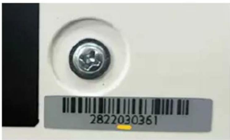
Identify the Hardware Revision
- Locate the Lot Code sticker on the Product Packaging or on the Mouse and Handheld Scanner Holders.
- Starting from the left, the Fifth and Sixth character indicate the Hardware Revision. (Figure a)
Note: Not all products will have this sticker. If it is missing, the revision is 01.
text_image
2822030361Figure a
Depending on the Hardware Revision, the assembly instructions have slight variations that will be detailed on that specific step.
To view manuals, videos, drivers, downloads, technical drawings, and more visit www.startech.com/support
Table of Contents
Compliance Statements......i
Safety Statements....ii
Warning Statements......iii
Identify the Hardware Revision ....xii
Product Diagram....1
Product Dimensions ......2
Front View 2
Top View 2
Side Views 3
Product Information 5
Requirements 5
Package Contents (Hardware Revision 04 and higher)....6
Package Contents (Hardware Revisions 01 to 03 only) 9
Installation Option #1 - Grommet Mount ...... 12
Attach the Grommet Assembly....12
Installation Option #2 - Desk Mount......16
Attach the Desk Clamp to a Desk or Table or to a Desk or Table Next to Wall 16
Clamp L Bracket Hardware Revisions....20
Attach the Monitor Arm to the Base (Hardware Revision 01 to 03 only)....23
Attach the Monitor Arm to the Base (Hardware Revision 04 and higher)....24
IMPORTANT! - Maintenance After Assembly (Hardware Revision 01 to 03 only)......25
Install the Mouse and Handheld Scanner Holders
(Hardware Revision 04 and higher only)....26
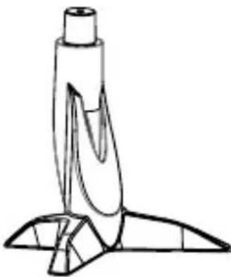
Attach the Column to the Keyboard Tray....27
Attach the Column to the Monitor Arm....30
Attach the VESA Monitor Mount to a Monitor....33
Attach the Monitor to the Column 35
Attach the Adhesive Strip to the Keyboard 37
Route the Cables 38
Operation 39
Remove the Monitor....39
Adjust the Tilt Angle of the Monitor....40
Adjust the Angle of Keyboard Tray 41
Counterbalance the Weight of the Monitor 42
Counterbalance the Weight of the Workstation 43
Adjust the Monitor Swivel Tension 44
Extend the Mouse Tray....45
Clean the Keyboard Tray Components....46
Warranty Information......47
Limitation of Liability 47
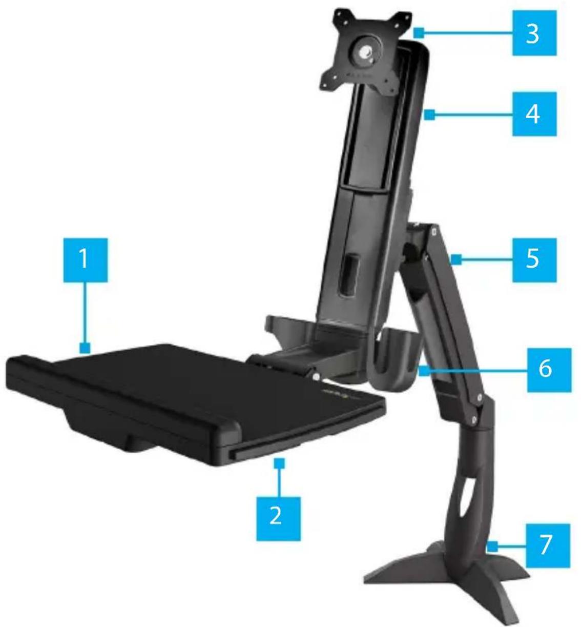
Product Diagram
text_image
1 2 3 4 5 6 7| 1 | Keyboard Tray | 5 | Monitor Arm |
| 2 | Mouse Tray | 6 | Mouse and Handheld Scanner Holders |
| 3 | VESA Monitor Mount | 7 | Base |
| 4 | Column | ||
To view manuals, videos, drivers, downloads, technical drawings, and more visit www.startech.com/support
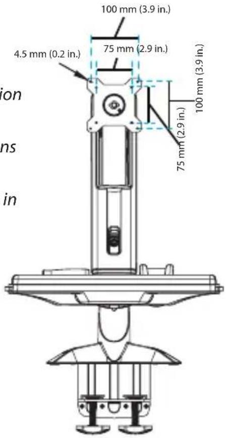
Product Dimensions
Front View
Note: Page 2, 3, and 4 show Hardware Revision 04 that has Hand Knobs to secure the Desk Clamp Assembly. Previous Hardware Revisions have a Clamp Screw Assembly instead. Refer to the respective assembly illustrations in the package contents.
text_image
100 mm (3.9 in.) 75 mm (2.9 in.) 4.5 mm (0.2 in.) 100 mm (3.9 in.) 75 mm (2.9 in.)Top View
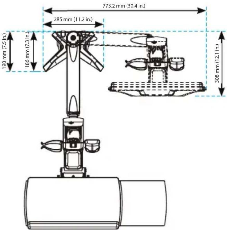
text_image
773.2 mm (30.4 in.) 285 mm (11.2 in.) 190 mm (7.5 in.) 186 mm (7.3 in.) 308 mm (12.1 in.)Side Views
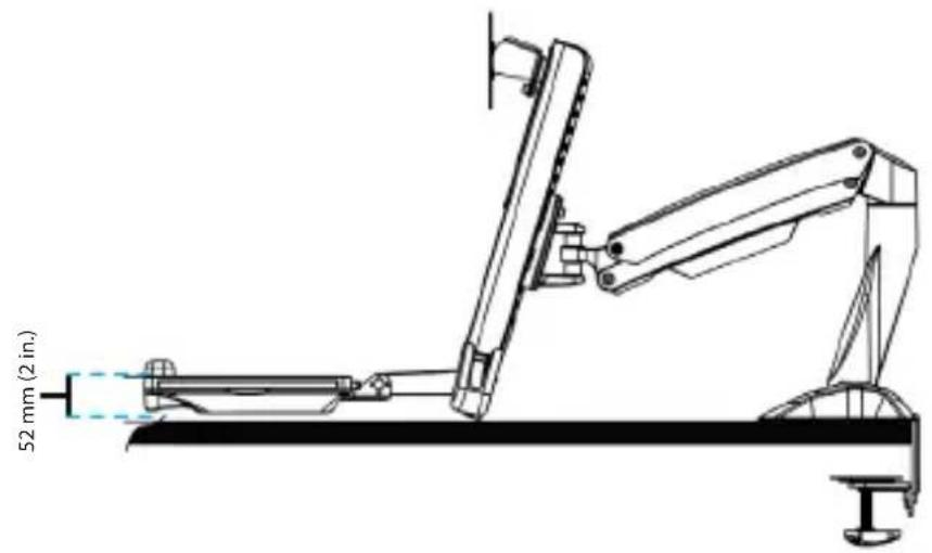
text_image
52 mm (2 in.)
text_image
530 mm (20.9 in.) 351 mm (13.8 in.) 489 mm (19.2 in.)To view manuals, videos, drivers, downloads, technical drawings, and more visit www.startech.com/support

text_image
Max 940 mm (37 in.) 351 mm to 530 mm (13.8 in. to 20.9 in.) 408.7 mm (16.1 in.) 166 mm (6.5 in.) 32.5 mm (1.3 in.) 890 mm (35 in.) 258 mm to 382 mm (10.1 in. to 15 in.) 14 mm to 450 mm (0.5 in. to 17.7 in.) 8 mm to 65 mm (0.3 in. to 2.6 in.) 124 mm (4.9 in.) 436 mm (17.2 in.) 396 mm to 832 mm (15.6 in. to 32.8 in.) 88 mm (3.5 in.) 260 mm (10.2 in.) 116 mm (4.5 in.)To view manuals, videos, drivers, downloads, technical drawings, and more visit www.startech.com/support
Product Information
Requirements
For the latest product information, technical specifications, manuals, and Declarations of Conformance, please visit:
www.StarTech.com/ARMSTSCP1
www.StarTech.com/SIT-STAND-ARM-1MS
Grommet Assembly
• Grommet hole with a diameter of 0.3 to 1.9 inches (8 to 50 mm)
- Desk or table between 0.3 to 1.9 inches (8 to 50 mm) thick
Desk Clamp
- Desk or table between 0.3 to 2.6 inches (8 to 65 mm) thick. For Hardware Revision 03 and higher
- Desk or table between 0.3 to 1.9 inches (8 to 50 mm) thick. For Hardware Revisions 01 and 02
- At least 0.3 inches (8 mm) of clearance between the table or desk and the wall
Monitor
• Weight of 4.4 to 17.6 lb (2 to 8 kg)
- Compatible VESA mounting hole pattern of 75 x 75 or 100 x 100 mm
- Display size up to 27" or 34" for ultrawide (landscape only)
Tools
• Phillips head screwdriver x 1
• Ratchet with 14 Inch socket
To view manuals, videos, drivers, downloads, technical drawings, and more visit www.startech.com/support
Package Contents (Hardware Revision 04 and higher)
 Monitor ArmQty: 1 Monitor ArmQty: 1 |  Keyboard TrayQty: 1 Keyboard TrayQty: 1 |  ColumnQty: 1 ColumnQty: 1 | 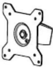 VESA Monitor MountQty: 1 VESA Monitor MountQty: 1 |
 BaseQty: 1 BaseQty: 1 |  Adhesive StripsQty: 2 Adhesive StripsQty: 2 | 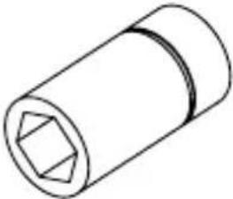 Socket DriverQty: 1 Socket DriverQty: 1 | 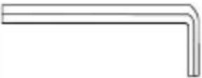 6 mm Hex KeyQty: 1 6 mm Hex KeyQty: 1 |
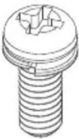
 M6 x 10 mmScrewsQty: 3 M6 x 10 mmScrewsQty: 3 |  M8 x 30 mmScrewsQty: 1 M8 x 30 mmScrewsQty: 1 |  Metal WasherQty: 1 Metal WasherQty: 1 | 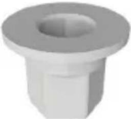 Plastic HexLocking NutQty: 1 Plastic HexLocking NutQty: 1 |
 Base ScrewsQty: 4 Base ScrewsQty: 4 |  M6 x 25 mmScrewsQty: 2 M6 x 25 mmScrewsQty: 2 | 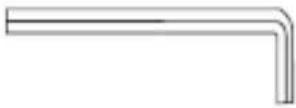 5 mm Hex KeyQty: 1 5 mm Hex KeyQty: 1 |  M6 x 12 mmScrewsQty: 4 M6 x 12 mmScrewsQty: 4 |
 M4 x 10 mmScrewsQty: 4 M4 x 10 mmScrewsQty: 4 |  2.5 mm Hex KeyQty: 1 2.5 mm Hex KeyQty: 1 | 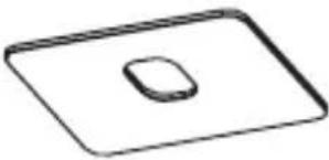 Base PadQty: 1 Base PadQty: 1 |  Clamp ScrewsQty: 4 Clamp ScrewsQty: 4 |
 Base PlateQty: 1 Base PlateQty: 1 |  Grommet PlateQty: 1 Grommet PlateQty: 1 | 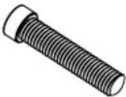 M8 x 65 mmScrewsQty: 1 M8 x 65 mmScrewsQty: 1 | 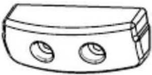 Keyboard TrayCapQty: 1 Keyboard TrayCapQty: 1 |
 Clamp L BracketQty: 1 Clamp L BracketQty: 1 |  Desk Clamp AssemblyQty: 1 Desk Clamp AssemblyQty: 1 | 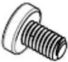 M6 x 8 mm ScrewQty: 1 M6 x 8 mm ScrewQty: 1 | 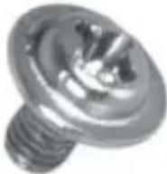 M3 x 8 mm ScrewsQty: 2 M3 x 8 mm ScrewsQty: 2 |
 Mouse and Handheld Scanner HoldersQty: 1 Mouse and Handheld Scanner HoldersQty: 1 |  User ManualQty: 1 User ManualQty: 1 | ||
To view manuals, videos, drivers, downloads, technical drawings, and more visit www.startech.com/support
Package Contents (Hardware Revisions 01 to 03 only)
 Monitor ArmQty: 1 Monitor ArmQty: 1 |  Keyboard TrayQty: 1 Keyboard TrayQty: 1 | 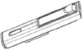 ColumnQty: 1 ColumnQty: 1 |  VESA Monitor MountQty: 1 VESA Monitor MountQty: 1 |
 BaseQty: 1 BaseQty: 1 | 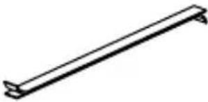 Adhesive StripsQty: 2 Adhesive StripsQty: 2 |  Socket DriverQty: 1 Socket DriverQty: 1 | 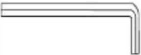 6 mm Hex KeyQty: 1 6 mm Hex KeyQty: 1 |
 M6 x 10 mmScrewsQty: 3 M6 x 10 mmScrewsQty: 3 |  M8 x 20 mmScrewsQty: 1 M8 x 20 mmScrewsQty: 1 |  Metal WasherQty: 1 Metal WasherQty: 1 |  Plastic WasherQty: 1 Plastic WasherQty: 1 |
| Base ScrewsQty: 4 | M6 x 25 mmScrewsQty: 2 | 5 mm Hex KeyQty: 1 | M6 x 12 mmScrewsQty: 4 |
| M4 x 10 mmScrewsQty: 4 | 2.5 mm Hex KeyQty: 1 | Base PadQty: 1 | Clamp ScrewsQty: 4 |
| Base PlateQty: 1 | Grommet PlateQty: 1 | M8 x 65 mmScrewsQty: 1 | Keyboard TrayCapQty: 1 |
 Clamp L BracketQty: 1 Clamp L BracketQty: 1 |  Clamp Screw AssemblyQty: 1 Clamp Screw AssemblyQty: 1 |  M6 x 8 mm ScrewQty: 1 M6 x 8 mm ScrewQty: 1 |  User ManualQty: 1 User ManualQty: 1 |
To view manuals, videos, drivers, downloads, technical drawings, and more visit www.startech.com/support
Installation Option #1 - Grommet Mount
Attach the Grommet Assembly
text_image
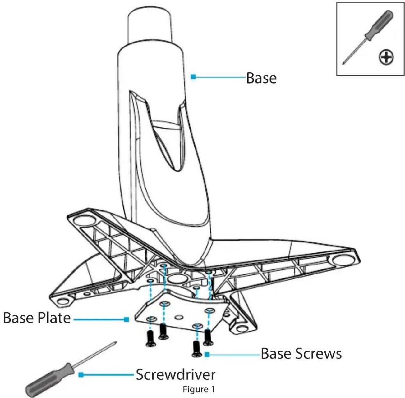
Base Base Plate Screwdriver Figure 1 Base Screws- Align the Base Plate with the Assembly Holes, located on the underside of the Base. (Figure 1)
To view manuals, videos, drivers, downloads, technical drawings, and more visit www.startech.com/support
- Insert the Base Screws (x 4) through the Base Plate and into the Base and tighten, using a Phillips Head Screwdriver.
(Figure 1)
text_image
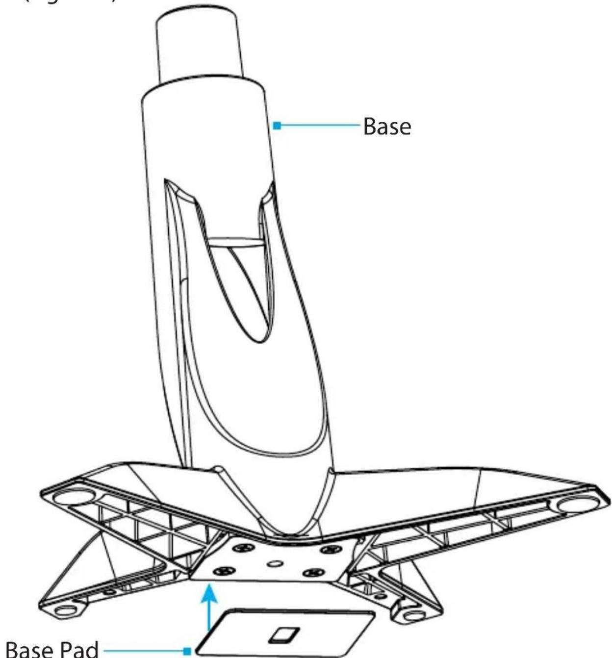
Base Base PadFigure 2
- Remove the Adhesive Backing from the Base Pad and affix the Base Pad to the underside of the Base to complete the Base Assembly. (Figure 2)
To view manuals, videos, drivers, downloads, technical drawings, and more visit www.startech.com/support

text_image
Base 0.3 to 1.9 inches 8 - 50 mm Grommet Plate M8 x 65 mm Screw 6 mm Hex KeyFigure 3
-
Thread the M8 x 65 mm Screw up through the underside of the Grommet Plate to complete the Screw Assembly.
-
Position the Base over a Grommet Hole in a Desk or Table.
To view manuals, videos, drivers, downloads, technical drawings, and more visit www.startech.com/support
-
Place Screw Assembly against the Grommet Hole on the underside of the Desk or Table.
-
Tighten the Screw Assembly, until the Grommet Plate is connected to the base and seated tightly against the Desk or Table, using the 6 mm Hex Key. (Figure 3)
Installation Option #2 - Desk Mount
Attach the Desk Clamp to a Desk or Table
-- or --
to a Desk or Table Next to a Wall
text_image
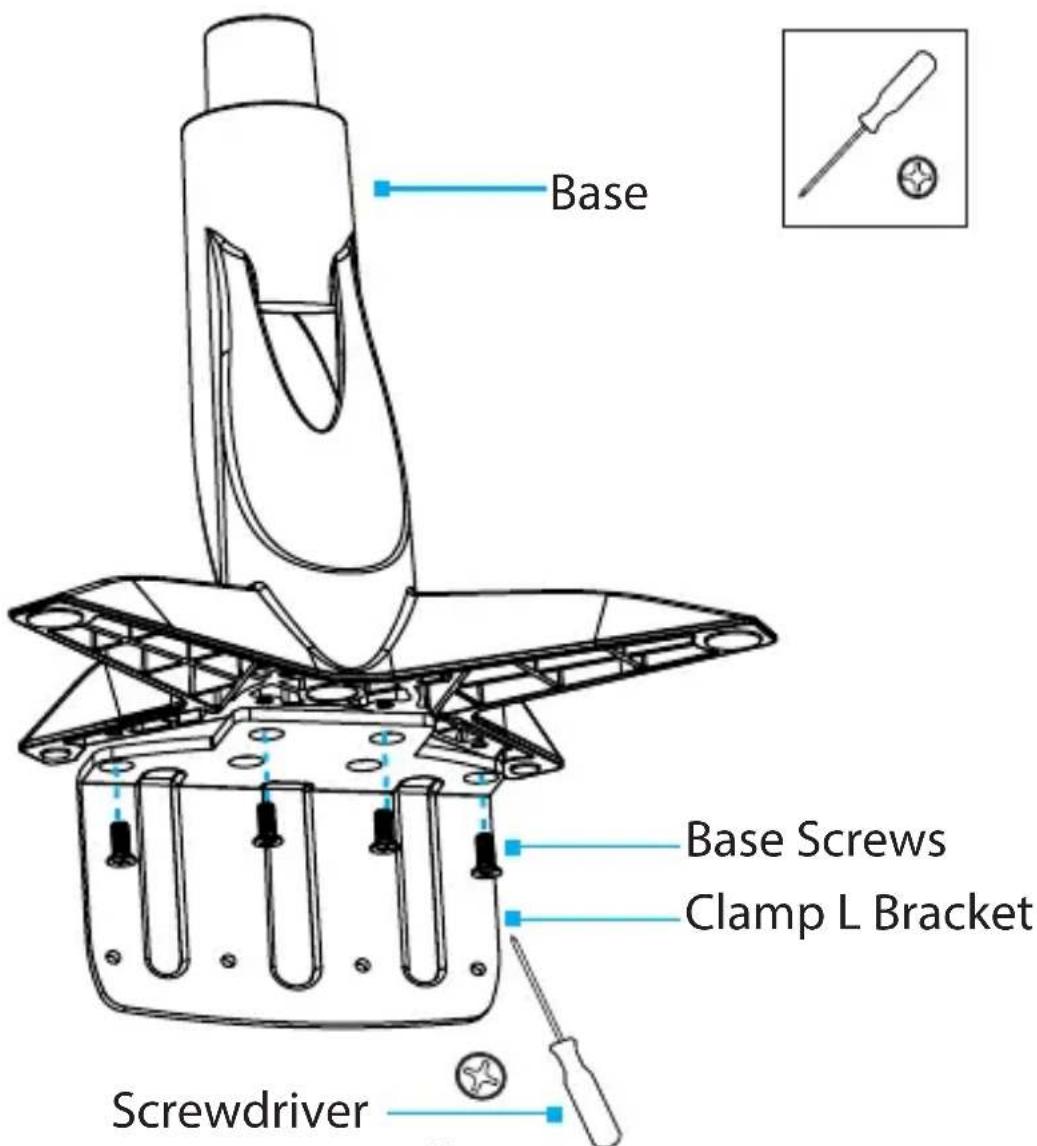
Base Base Screws Clamp L Bracket ScrewdriverFigure 4
Note: To attach the Desk Clamp to a Desk or Table that is situated against a Wall, at least 8 mm of space is required between the edge of the mounting surface and the wall.
To view manuals, videos, drivers, downloads, technical drawings, and more visit www.startech.com/support
- Align the Clamp L Bracket with the Assembly Holes, located on the underside of the Base. (Figure 4)
- Insert the Base Screws (x 4) through the Clamp L Bracket and into the Base and tighten, using a Phillips Head Screwdriver.
text_image
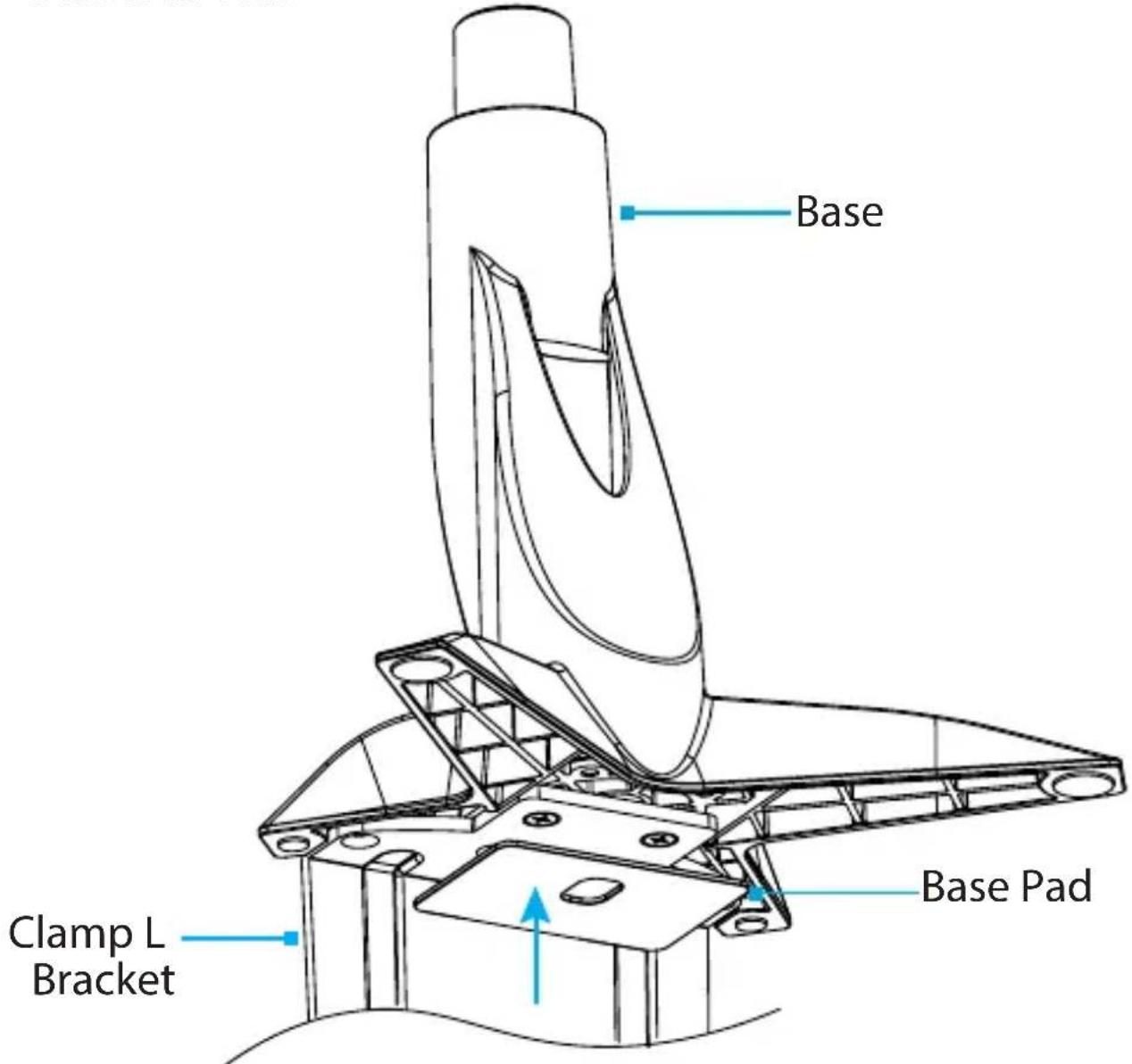
Base Clamp L Bracket Base PadFigure 5
- Remove the Adhesive Backing from the Base Pad and affix the Base Pad to the underside of the Clamp L Bracket to complete the Base Assembly. (Figure 5)
To view manuals, videos, drivers, downloads, technical drawings, and more visit www.startech.com/support
text_image
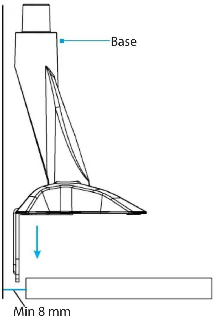
Base Min 8 mmFigure 6
- (For a standalone Desk or Table) Hold the Base Assembly flush up against the edge of the Desk or Table.
-- or -- (For a Desk or Table against a wall) Slide the Base Assembly between the Desk or Table and the Wall. The Base Assembly should be flush up against the edge of the Desk or Table. (Figure 6)
To view manuals, videos, drivers, downloads, technical drawings, and more visit www.startech.com/support
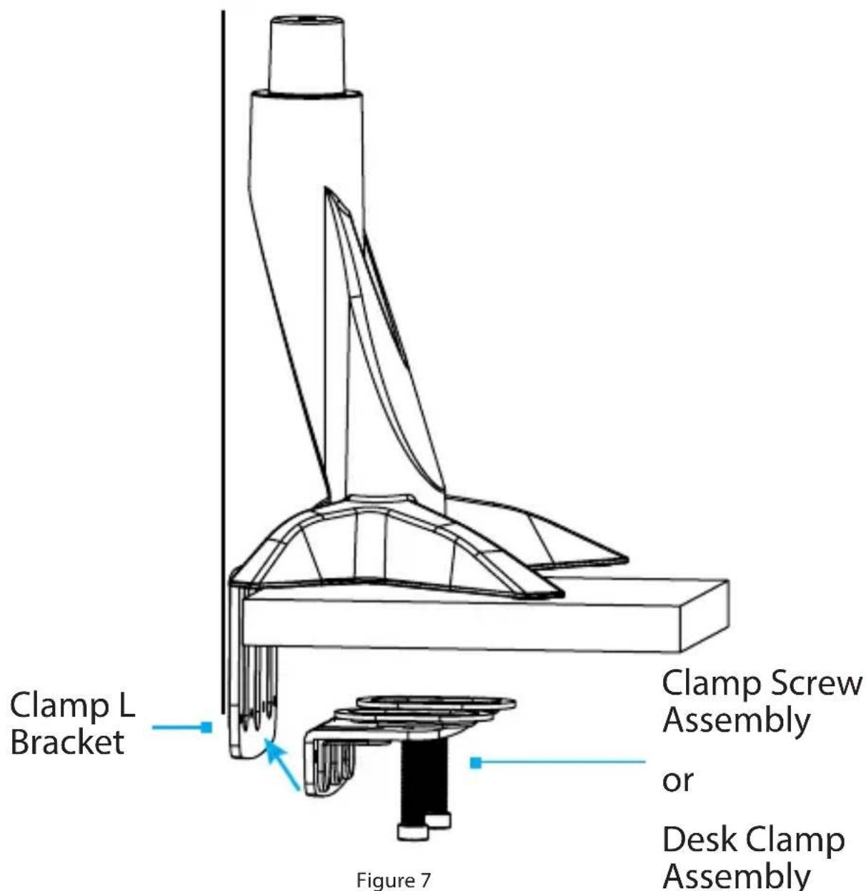
text_image
Clamp L Bracket Figure 7 Clamp Screw Assembly or Desk Clamp Assembly- Align the Mounting Holes (x 4), located on the Clamp Screw Assembly (Hardware Revision 01 to 03) or Desk Clamp Assembly (Hardware Revision 04 and higher), with the Threaded Holes (x 4), located on the Clamp L Bracket. (Figure 7)
Note: Depending on the Hardware Revision, the Clamp L Bracket will have either one or two rows of Threaded Holes. Refer to Page 20 for more information.
To view manuals, videos, drivers, downloads, technical drawings, and more visit www.startech.com/support
Clamp L Bracket Hardware Revisions
text_image
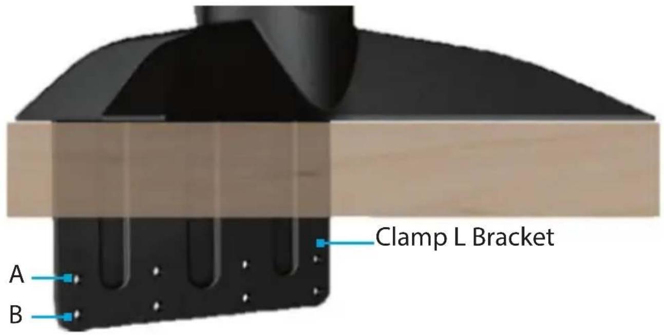
Clamp L Bracket A BFigure b
To accommodate different Desk or Table thicknesses, the Clamp L Bracket has One or Two Rows of Threaded Holes. (Figure b)
- Row A for thickness, 0.3 to 1.9 inches (8 to 50 mm). Available for all Hardware Revisions.
- Row B for thickness, 0.9 to 2.5 inches (23 to 65 mm). Available on Hardware Revision 03 and higher.
Continue to Step 6 on Page 21.

text_image
Clamp Screws 5 mm Hex Key Figure 8- Insert the Clamp Screws (x 4) through the Clamp Screw Assembly (Hardware Revision 01 to 03) or Desk Clamp Assembly (Hardware Revision 04 or higher) and into the Threaded Holes (x 4) located on the Clamp L Bracket and tighten using the 5 mm Hex Key. (Figure 8)
To view manuals, videos, drivers, downloads, technical drawings, and more visit www.startech.com/support
text_image
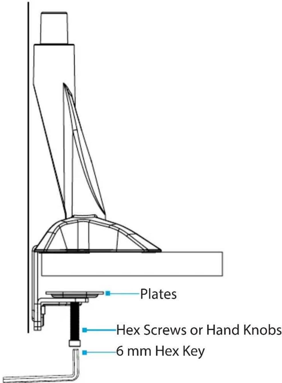
Plates Hex Screws or Hand Knobs 6 mm Hex KeyFigure 9
- Tighten the Hex Screws (Hardware Revision 01 to 03) using the 6 mm Hex Key or Tighten the Hand Knobs (Hardware Revision 04 and higher). Tighten until the Plates are seated tightly against the Desk or Table. (Figure 9)
To view manuals, videos, drivers, downloads, technical drawings, and more visit www.startech.com/support
Attach the Monitor Arm to the Base
For Hardware Revisions 01 to 03 only
Note: Users of Hardware Revision 04 and higher continue to Page 24.

text_image
Monitor Arm 6 mm Hex Key M8 x 20 mm Screw Metal Washer Plastic Washer Projection Base Figure 10- Attach the Monitor Arm onto the Projection, located on the Base.
- Place the Plastic Washer into the Joint of the Monitor Arm. Continue to Step 3 on Page 25.
To view manuals, videos, drivers, downloads, technical drawings, and more visit www.startech.com/support
Attach the Monitor Arm to the Base For Hardware Revisions 04 and higher
text_image
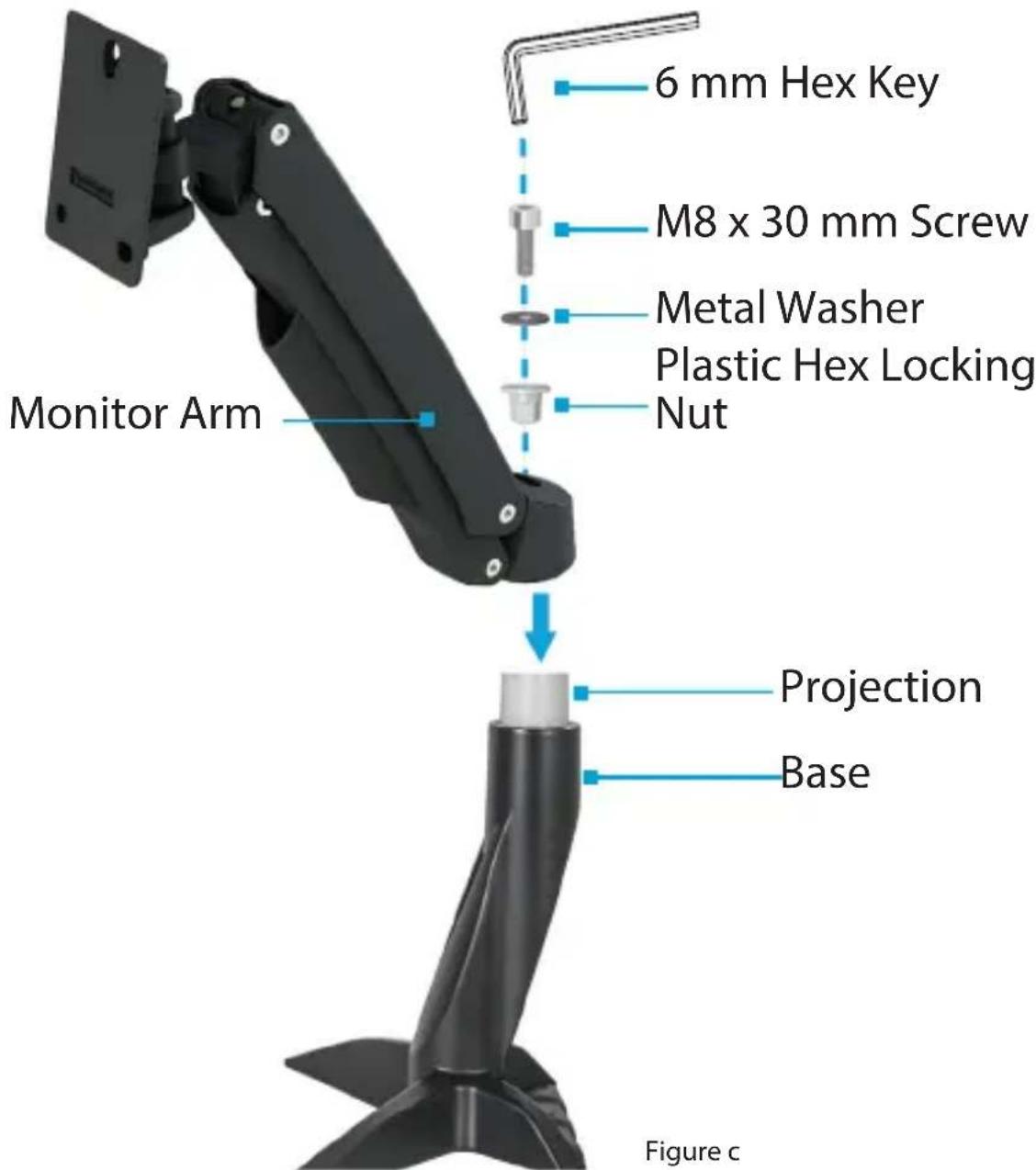
6 mm Hex Key M8 x 30 mm Screw Metal Washer Plastic Hex Locking Nut Monitor Arm Projection Base Figure c-
Attach the Monitor Arm onto the Projection, located on the Base.
-
Place the Plastic Hex Locking Nut through the Monitor Arm and into the pocket in the Projection. Continue to Step 3 on Page 25.
To view manuals, videos, drivers, downloads, technical drawings, and more visit www.startech.com/support
- Place the Metal Washer into the Joint of the Monitor Arm.
- Insert the M8 x 20 mm Screw (Hardware Revision 01 to 03) or the M8 x 30 mm Screw (Hardware Revision 04 and higher) through the Washers and into the Joint, located in the Monitor Arm, and tighten, using the 6 mm Hex Key. (Figure 10 or Figure c)
IMPORTANT! - Maintenance After Assembly
For Hardware Revisions 01 to 03 only
In some use cases, frequent movement of the Monitor Arm can loosen the M8 x 20mm Screw that attaches the Monitor Arm to the Projection, located on the Base.
Periodic inspection of this M8 x 20mm Screw is required. If the M8 x 20mm Screw has loosened due to frequent movement, tighten the M8 x 20 mm Screw using the 6 mm Hex Key.
(Figure 11)

natural_image
Technical line drawing of a mechanical lever assembly (no text or symbols)Figure 11
To view manuals, videos, drivers, downloads, technical drawings, and more visit www.startech.com/support
Install the Mouse and Handheld Scanner Holders Hardware Revision 04 and higher only
Note: Users of Hardware Revision 01 to 03 continue to Page 27.
- Secure the Mouse and Handheld Scanner Holders to the Back of the Keyboard Tray using the M3 x 8 mm Screws (x 2) and a Phillips Head Screwdriver. Continue to Page 27. (Figure d)

text_image
Keyboard Tray Mouse and Handheld Scanner Holders M3 x 8 mm ScrewsFigure d
To view manuals, videos, drivers, downloads, technical drawings, and more visit www.startech.com/support
Attach the Column to the Keyboard Tray
text_image
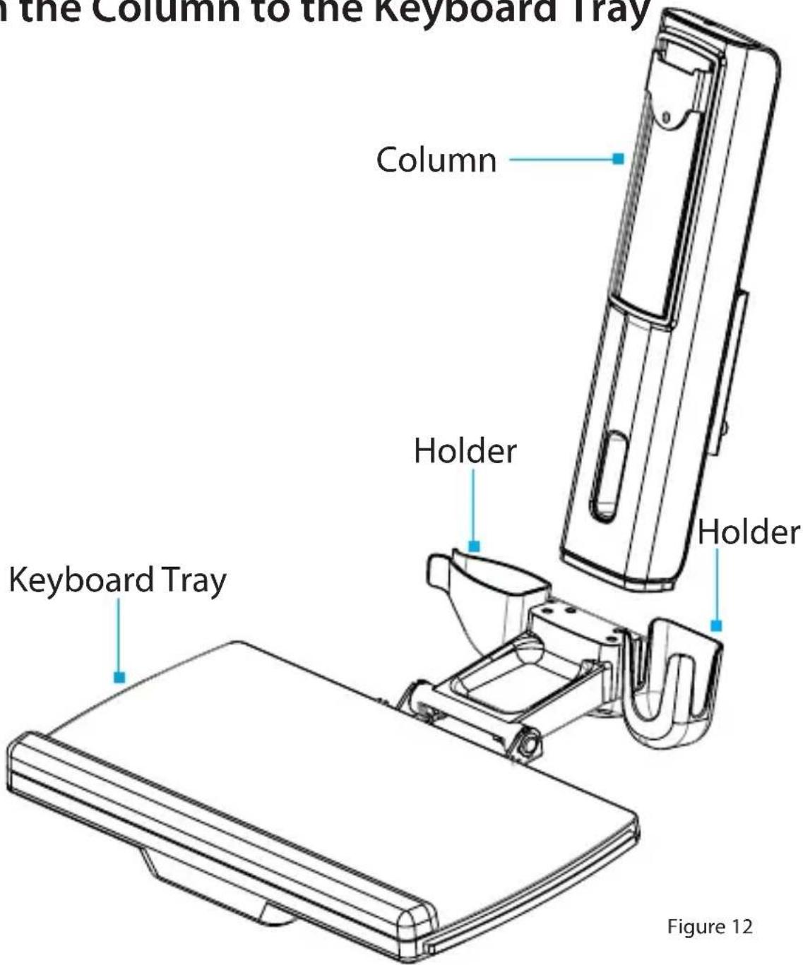
the Column to the Keyboard Tray Column Holder Holder Keyboard Tray Figure 12-
Orient the Column with the cutout located on the bottom half of the Column.
-
Align the Assembly Holes, located on the bottom of the Column, with the Assembly Holes, located between the Holders on the Keyboard Tray. (Figure 12)
To view manuals, videos, drivers, downloads, technical drawings, and more visit www.startech.com/support
text_image
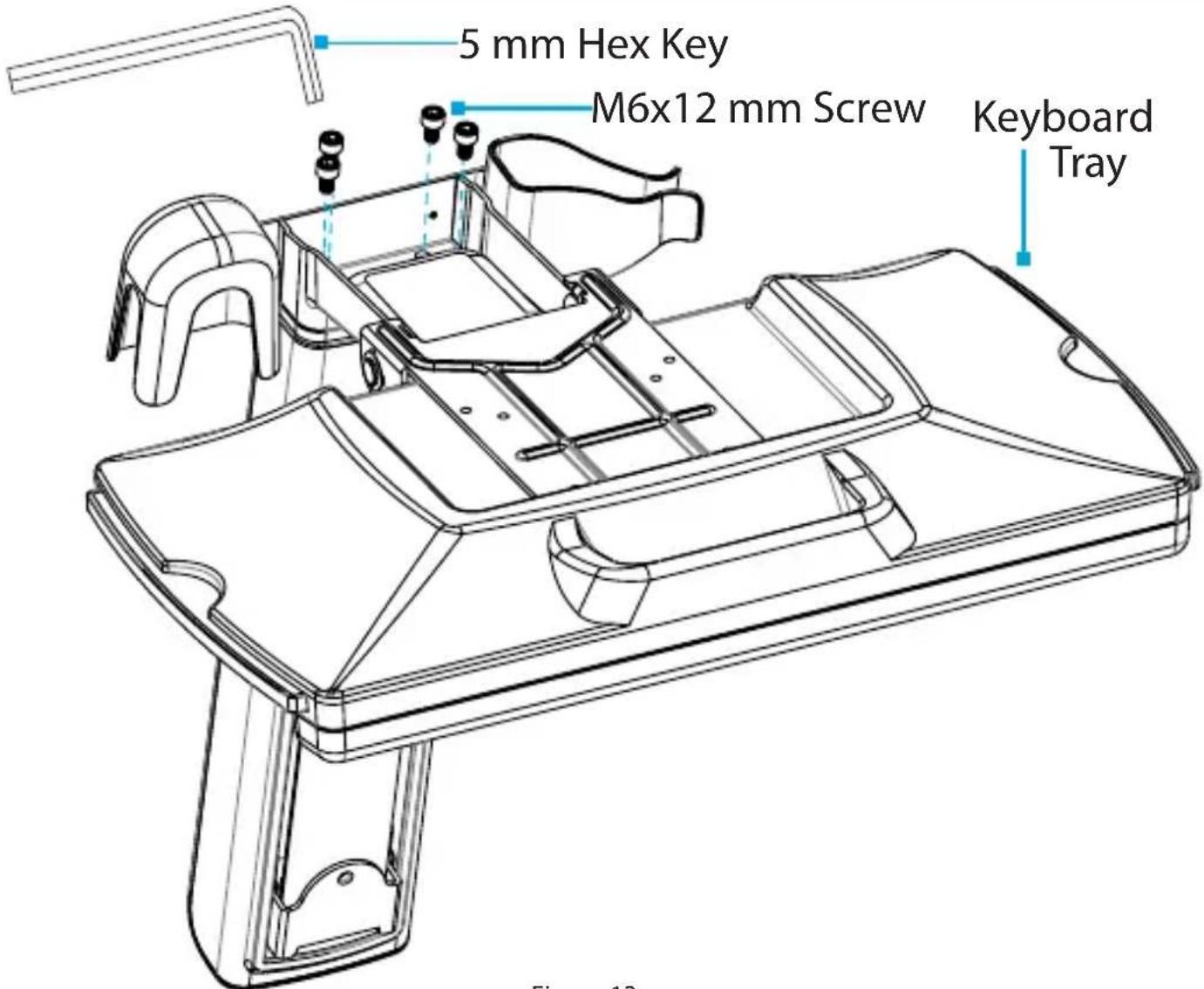
5 mm Hex Key M6x12 mm Screw Keyboard Tray Figure 13Figure 13
- Insert the M6 x 12 mm Screws through the Assembly Holes, located in the Keyboard Tray, and into the Column and tighten, using the 5 mm Hex Key. (Figure 13)
To view manuals, videos, drivers, downloads, technical drawings, and more visit www.startech.com/support
text_image
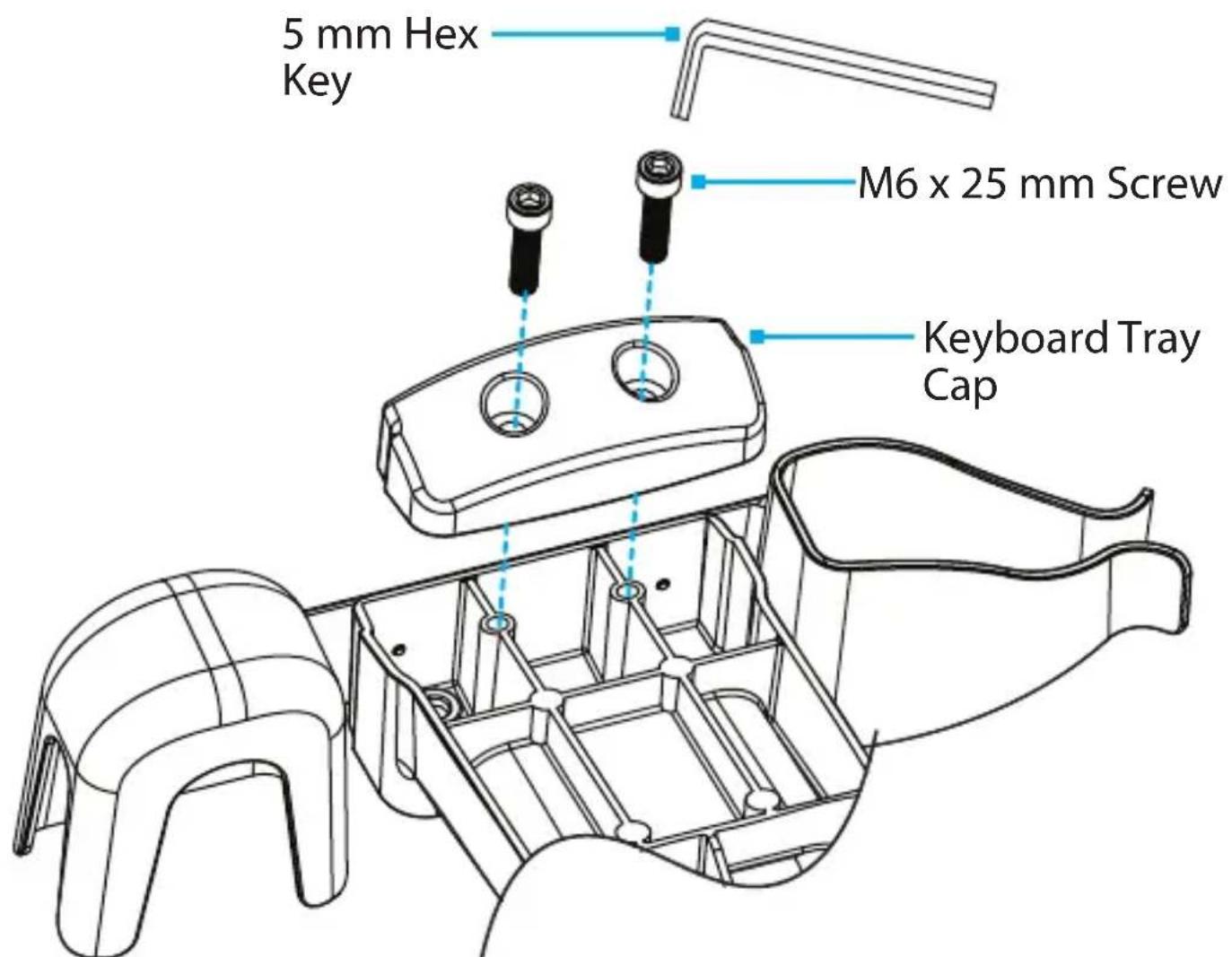
5 mm Hex Key M6 x 25 mm Screw Keyboard Tray CapFigure 14
-
Place the Keyboard Tray Cap over the Assembly Holes, located on the underside of the Keyboard Tray.
-
Insert the M6 x 25 mm Screws (x 2) through Assembly Holes, located in the Keyboard Tray Cap, and into the Keyboard Tray and tighten, using the 5 mm Hex Key to complete the Column Assembly. (Figure 14)
To view manuals, videos, drivers, downloads, technical drawings, and more visit www.startech.com/support
Attach the Column to the Monitor Arm
text_image
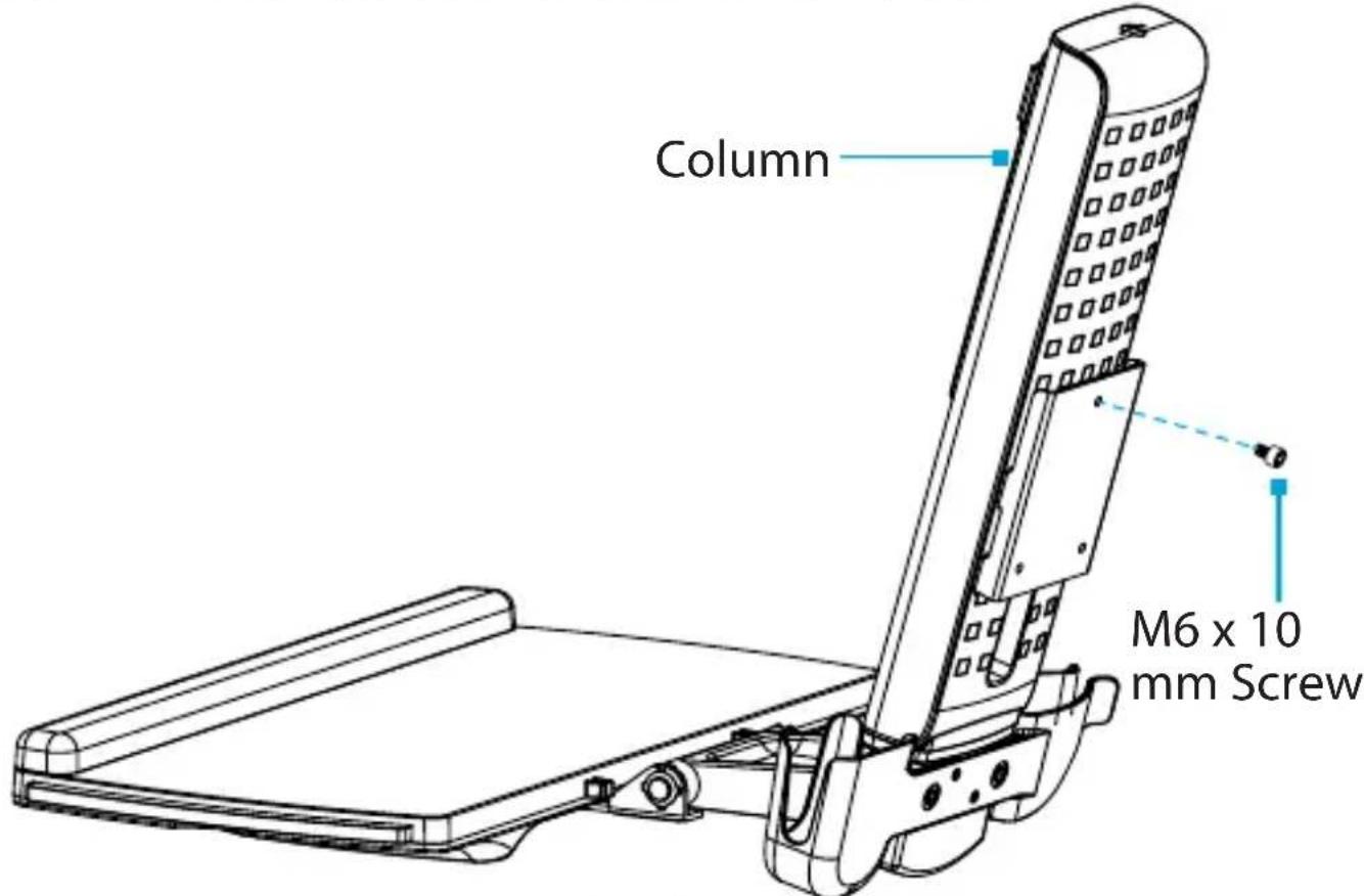
Column M6 x 10 mm ScrewFigure 15
- Thread an M6 x 10 mm Screw into the Mounting Hole, located in the top of the Plate on the back of the Column. (Figure 15)
Note: Do not fully tighten the M6 x 10 mm Screw and ensure 0.16 to 0.20 inches (4 to 5 mm) of space is left between the Plate and the Screw.
To view manuals, videos, drivers, downloads, technical drawings, and more visit www.startech.com/support

text_image
M6 x 10 mm Screw Key-shaped Hole Monitor Arm Figure 16Figure 16
- Hook the M6 x 10 mm Screw, attached to the column, into the Key-Shaped Hole, located at the top of the Plate on the Monitor Arm. (Figure 16)
To view manuals, videos, drivers, downloads, technical drawings, and more visit www.startech.com/support

text_image
Monitor Arm M6 x 10 mm Screw 5 mm Hex KeyFigure 17
- Insert the second M6 x 10 mm Screw into the hole, located on the Plate on the Monitor Arm and tighten, using the 5 mm Hex Key. (Figure 17)
To view manuals, videos, drivers, downloads, technical drawings, and more visit www.startech.com/support
Attach the VESA Monitor Mount to a Monitor

text_image
VESA Monitor Mount Screw ScrewdriverFigure 18
- To enable 360 degree rotation of the Monitor, remove the Screw, located in the face of the VESA Monitor Mount, using a Phillips Head Screwdriver. (Figure 18)
Note: If using an ultrawide monitor, refrain from rotating to the portrait position. The sides of the monitor could collide with the Keyboard Tray and damage the monitor.
To view manuals, videos, drivers, downloads, technical drawings, and more visit www.startech.com/support

text_image
Screwdriver M4x10 mm Screws Bottom of Monitor VESA Monitor MountFigure 19
- Position the VESA Monitor Mount so the Projection, located on the back of the VESA Monitor Mount, is pointing towards the bottom of the Monitor.
- Align the VESA Monitor Mount with the Mounting Holes, located on the back of the Monitor.
- Insert the M4 x 10 mm Screws (x 4) through the VESA Monitor Mount and into the Monitor and tighten, using a Phillips Head Screwdriver. (Figure 19)
Warning! Do not over-tighten the Screws. If you encounter resistance while tightening the Screws, stop tightening.
To view manuals, videos, drivers, downloads, technical drawings, and more visit www.startech.com/support
Attach the Monitor to the Column
text_image
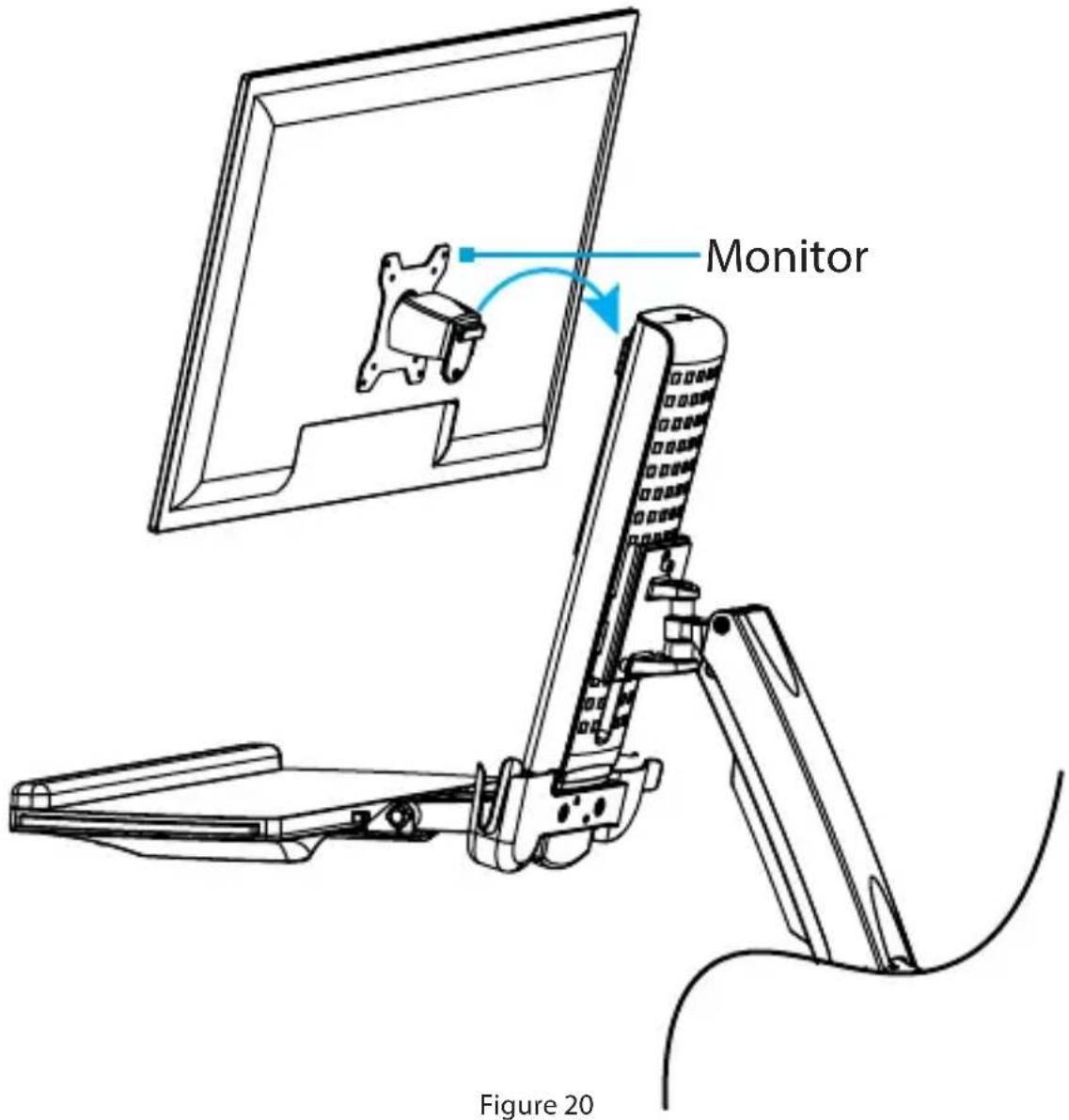
Monitor Figure 20Note: Two people are required to complete these steps safely. The second person should hold the Monitor Arm to ensure it does not drop unexpectedly due to weight of the added equipment.
- Hook the back of the VESA Monitor Mount onto the Plate, located on the Column. (Figure 20)
To view manuals, videos, drivers, downloads, technical drawings, and more visit www.startech.com/support

text_image
VESA Monitor Mount M6 x 8 mm Screw 5 mm Hex Key Figure 21- Insert the M6 x 8 mm Screw through the Projection, located on back of the VESA Monitor Mount and into the Plate, located on the Column and tighten, using the 5 mm Hex Key. (Figure 21)
To view manuals, videos, drivers, downloads, technical drawings, and more visit www.startech.com/support
Attach the Adhesive Strip to the Keyboard

text_image
Keyboard Adhesive StripFigure 22
Note: The Adhesive Strip will keep the keyboard in place when the Keyboard Tray is rotated 90°.
- Cut the Adhesive Strip to fit the length of your Keyboard.
- Peel apart the Adhesive Strip to create two pieces.
- Remove the Plastic Backing from one piece of the Adhesive Strip and stick it to the bottom of a Keyboard.
- Remove the Plastic Backing from the second piece of the Adhesive Strip and stick it to the surface of the Keyboard Tray so that it is aligned with the strip on the Keyboard. (Figure 22)
To view manuals, videos, drivers, downloads, technical drawings, and more visit www.startech.com/support
Route the Cables
text_image
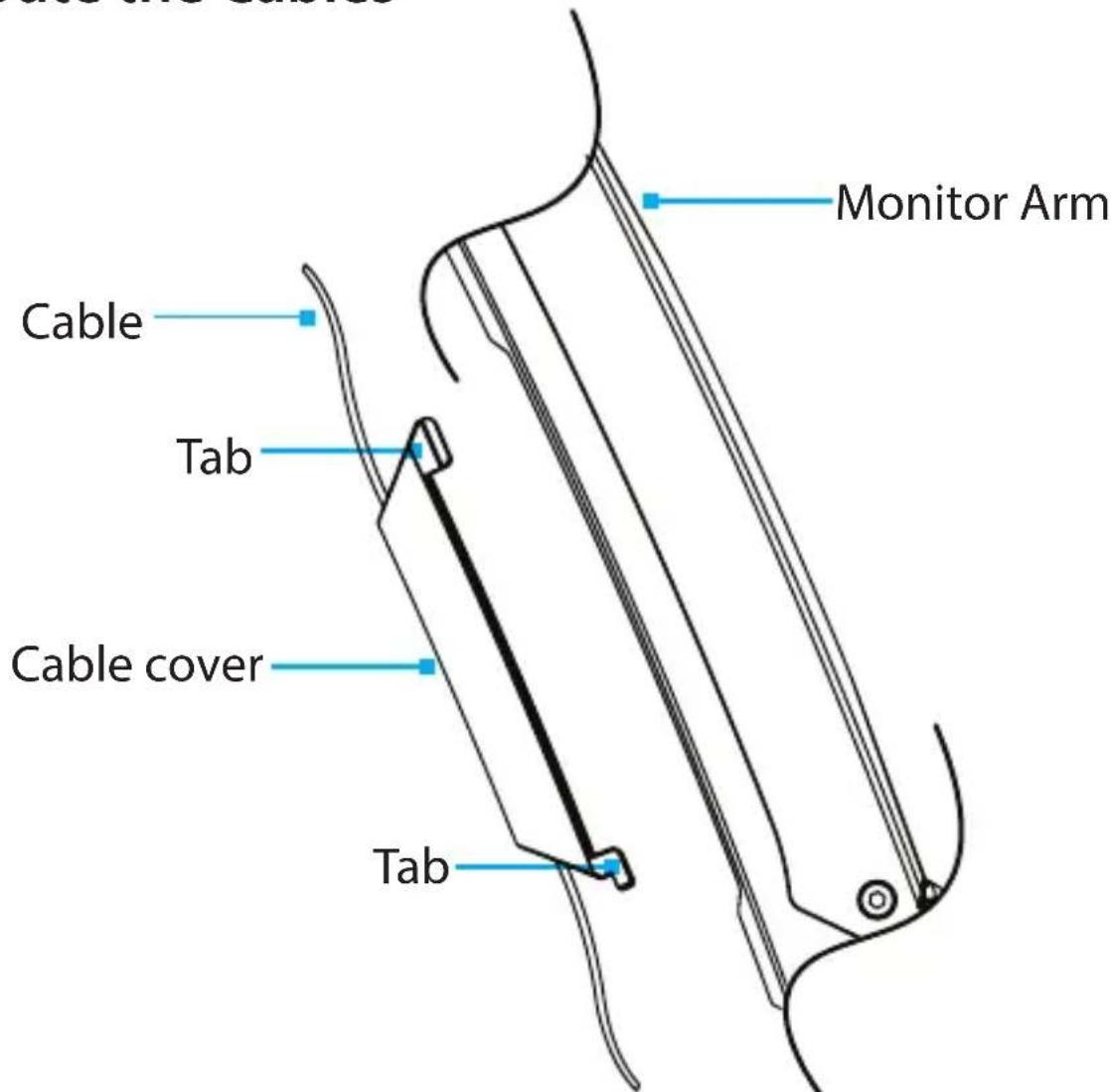
Monitor Arm Cable Tab Cable cover TabFigure 23
- Route the Cables along the Column and through the Slot, located at the base of the Column.
- Squeeze the Tabs, located at the top of the Cable Cover, and gently slide up, lift, and pull the Cable Cover off of the Monitor Arm.
Caution! Be careful not to snap the Tabs off the Cable Cover during removal.
- Route the Cables along the inside of the Cable Cover. (Figure 23)
To view manuals, videos, drivers, downloads, technical drawings, and more visit www.startech.com/support
- Squeeze the Tabs, located at the top of the Cable Cover, and gently slide down, drop, and push the Cable Cover into the Monitor Arm.
Operation
Remove the Monitor
Stored Energy Hazard! This product contains a spring mechanism which can cause the assembly and/or mounted equipment to move forcibly, and quickly, upwards. Always exercise caution when handling, or in close proximity to, the spring arm(s). Do not remove the mounted equipment unless the spring arm is moved to the highest position or (if possible) the spring force is adequately lowered to remove any danger posed. Failure to do so may result in property damage and/or serious personal injury.

text_image
Monitor 5 mm Hex Key Figure 24- Disconnect all Cables attached to the Monitor.
- Remove the M6 x 8 mm Screw, using the 5 mm Hex Key.
- Lift the VESA Monitor Mount off the Plate, located on the Column. (Figure 24)
Adjust the Tilt Angle of the Monitor

text_image
VESA Monitor Mount Adjustment Screw 2.5 mm Hex KeyFigure 25
- Adjust the Screw, located in the top of the VESA Monitor Mount, to increase or decrease the tilt angle of the Monitor. (Figure 25)
To view manuals, videos, drivers, downloads, technical drawings, and more visit www.startech.com/support
Adjust the Angle of Keyboard Tray

text_image
Keyboard Tray HandleFigure 26
- Grab the Keyboard Tray by the sides or use the Handle. Pull Up or Push Down on the Keyboard Tray to adjust the angle between 0° to 90°. (Figure 26)
Note: If rotating the Keyboard Tray on a steep angle, place the Mouse in the Mouse and Handheld Scanner Holders to stow it away.
To view manuals, videos, drivers, downloads, technical drawings, and more visit www.startech.com/support
Counterbalance the Weight of the Monitor

text_image
Column Adjustment Screw 5 mm Hex KeyFigure 27
To use the one-touch height adjustment feature, the weight of the Monitor must be counterbalanced with the tension of the One-Touch Height Adjustment Spring.
- If the Monitor doesn't remain in the set position, or it's difficult to raise or lower) use the 5 mm Hex Key to turn the Screw, located in the top of the Column, to adjust the tension of the One-Touch Height Adjustment Spring. (Figure 27)
To view manuals, videos, drivers, downloads, technical drawings, and more visit www.startech.com/support
Counterbalance the Weight of the Workstation

text_image
Ratchet 1/4in Socket Adjustment Screw Figure 28To use the One-Touch Height Adjustment feature, the weight of the Workstation must be counterbalanced with the tension of the One-Touch Height Adjustment Spring.
- If the Workstation doesn't remain in the set position, or it's difficult to raise or lower, use a Ratchet with the 1/4 inch (8 mm) Socket to turn the Screw in the hinge of the Monitor Arm to adjust the tension of the One-Touch Height Adjustment Spring. (Figure 28)
To view manuals, videos, drivers, downloads, technical drawings, and more visit www.startech.com/support
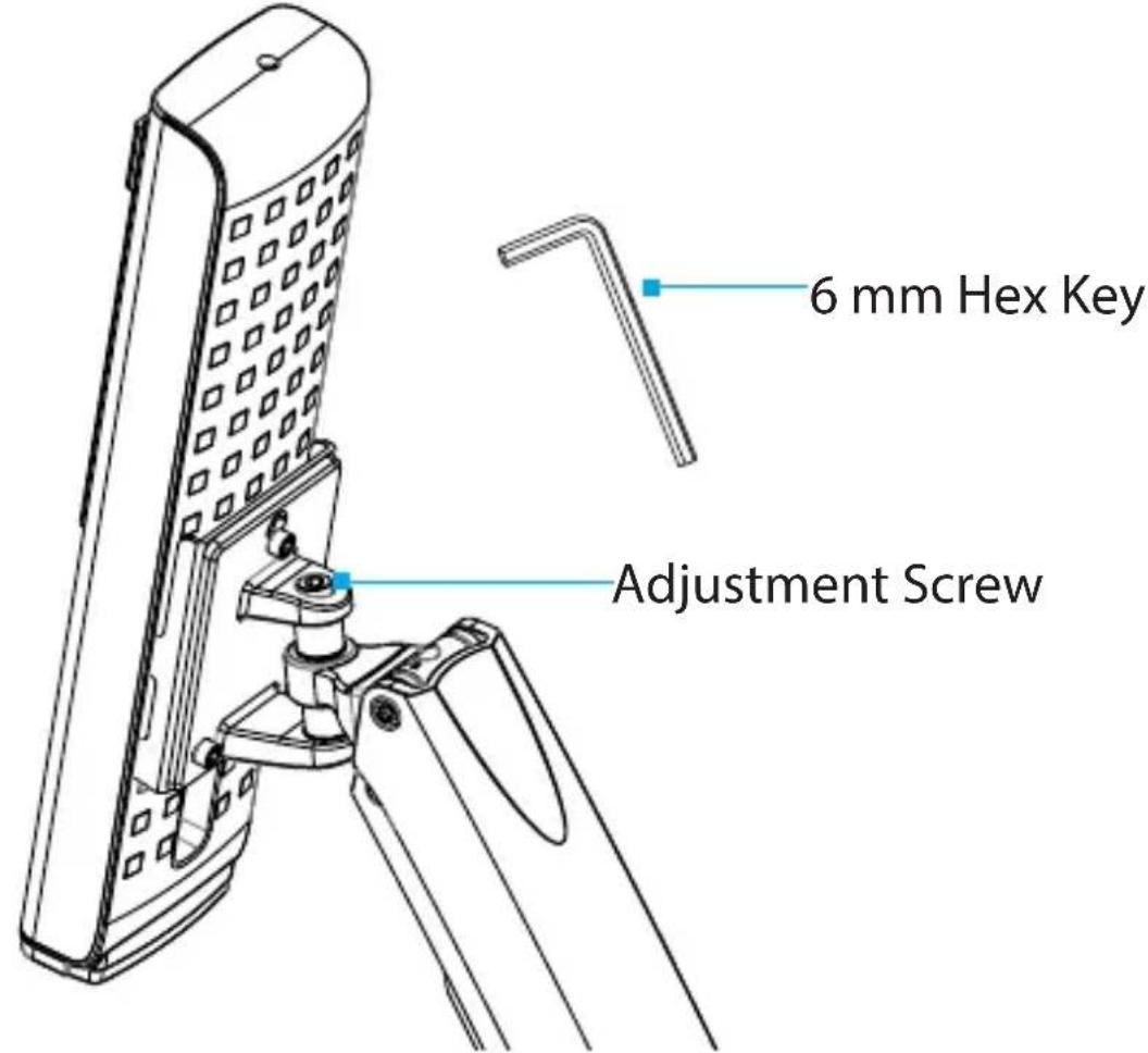
Adjust the Monitor Swivel Tension
text_image
6 mm Hex Key Adjustment ScrewFigure 29
- Use the Adjustment Screw located on the swivel point of the Monitor Arm, to increase or decrease the Swivel effort. (Figure 29)
To view manuals, videos, drivers, downloads, technical drawings, and more visit www.startech.com/support
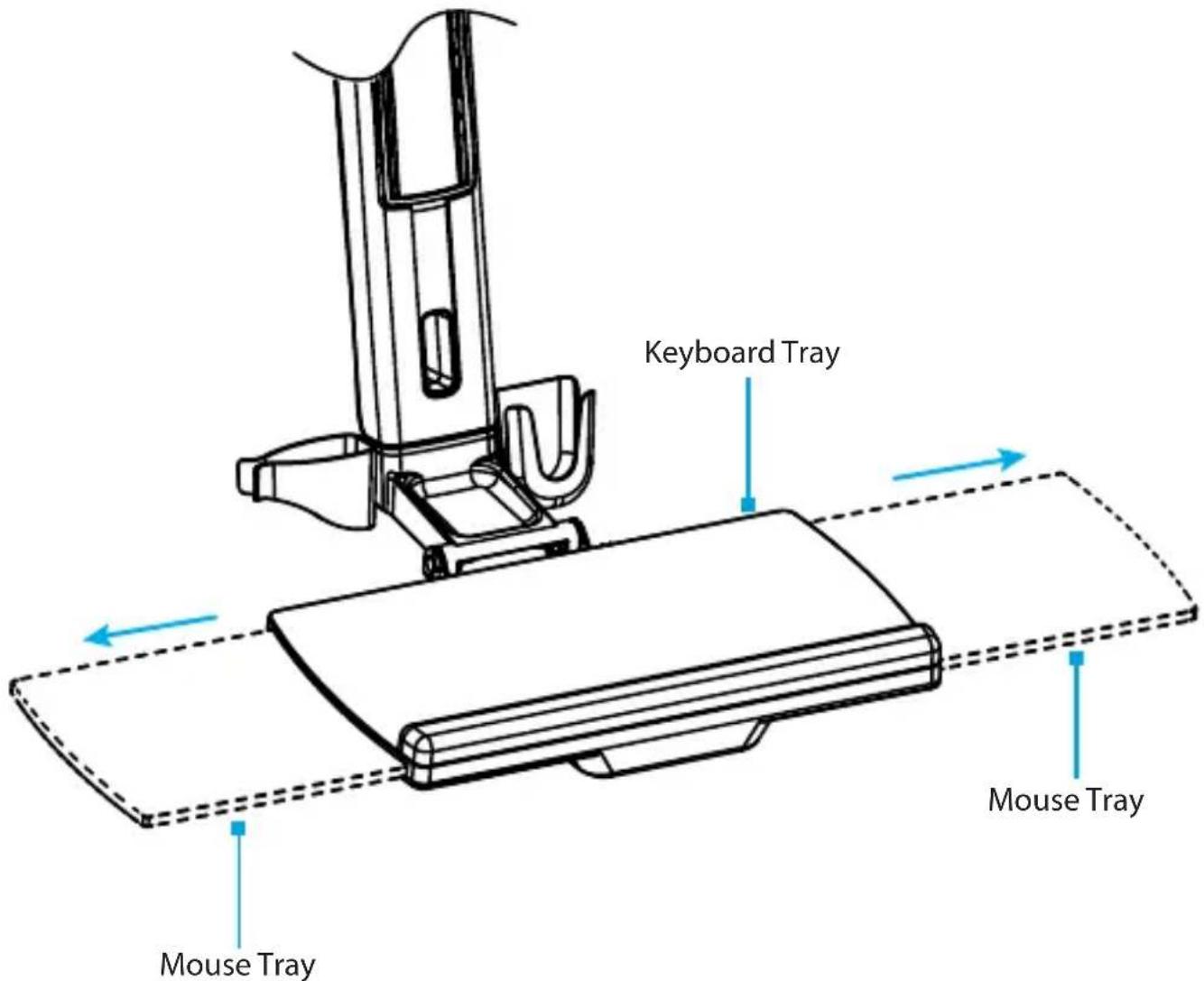
Extend the Mouse Tray
text_image
Keyboard Tray Mouse Tray Mouse TrayFigure 30
- Extend the Mouse Tray by on the underside of the Keyboard Tray by pulling it either to the Left or Right. (Figure 30)
Note: The Mouse Tray can be stowed inside the Keyboard Tray by Pushing it in.
In order to extend the Mouse Tray towards one side or the other, the Mouse Tray must be on its initial center position.
To view manuals, videos, drivers, downloads, technical drawings, and more visit www.startech.com/support
Clean the Keyboard Tray Components

text_image
Wrist Rest Figure 31 Mouse Tray Ejection Hole Mouse Tray Ejection Hole Figure 32-
Carefully peel the Plastic Wrist Rest off the Keyboard Tray. (Figure 31)
-
Extend the Mouse Tray to the Left or Right.
-
Insert a Pin or other fine object into one of the two Ejection Holes, located on the underside of the Keyboard Tray, to depress a plastic clip and pull the Mouse Tray. (Figure 32)
-
Clean the Plastic Wrist Rest and Mouse Tray in Warm Water mixed with a Non-abrasive Plastic-safe Cleaner.
To view manuals, videos, drivers, downloads, technical drawings, and more visit www.startech.com/support
Warranty Information
This product is backed by a two-year warranty.
For further information on product warranty terms and conditions, please refer to www.startech.com/warranty.
Limitation of Liability
In no event shall the liability of StarTech.com Ltd. and StarTech.com USA LLP (or their officers, directors, employees or agents) for any damages (whether direct or indirect, special, punitive, incidental, consequential, or otherwise), loss of profits, loss of business, or any pecuniary loss, arising out of or related to the use of the product exceed the actual price paid for the product.
Some states do not allow the exclusion or limitation of incidental or consequential damages. If such laws apply, the limitations or exclusions contained in this statement may not apply to you.
To view manuals, videos, drivers, downloads, technical drawings, and more visit www.startech.com/support
Hard-to-find made easy. At StarTech.com, that isn't a slogan. It's a promise.
StarTech.com is your one-stop source for every connectivity part you need. From the latest technology to legacy products — and all the parts that bridge the old and new — we can help you find the parts that connect your solutions.
We make it easy to locate the parts, and we quickly deliver them wherever they need to go. Just talk to one of our tech advisors or visit our website. You'll be connected to the products you need in no time.
Visit www.startech.com for complete information on all StarTech.com products and to access exclusive resources and time-saving tools.
StarTech.com is an ISO 9001 registered manufacturer of connectivity and technology parts since 1985 with operations around the world.
Reviews
Share your experiences using StarTech.com products, including product applications and setup, what you love about the products, and areas for improvement.

flowchart
graph LR
    A["FR"] --> B["Document"]
    B --> C["Recycle Bin"]
    D["Pensez à donner ou recycler"] --> E["ASSOCIATION"]
    E --> F["OU OU"]
    F --> G["MAGASIN DÉCHÈTERIE"]
www.quefairedemesdechets.fr
StarTech.com Ltd.
45 Artisans Crescent
London, Ontario
N5V 5E9
Canada
StarTech.com LLP
4490 South Hamilton
Road
Groveport, Ohio
43125
U.S.A.
StarTech.com Ltd.
Unit B, Pinnacle 15
Gowerton Road
Brackmills,
Northampton
NN4 7BW
United Kingdom
StarTech.com Ltd.
Siriusdreef 17-27
2132 WT Hoofddorp
The Netherlands
FR: fr.startech.com
DE: de.startech.com
ES: es.startech.com
NL: nl.startech.com
IT: it.startech.com
JP: jp.startech.com
To view manuals, videos, drivers, downloads, technical drawings, and more visit www.startech.com/support