ATA6562 - Kit d'évaluation Microchip - Free user manual and instructions
Find the device manual for free ATA6562 Microchip in PDF.

User questions about ATA6562 Microchip
0 question about this device. Answer the ones you know or ask your own.
Ask a new question about this device
Download the instructions for your Kit d'évaluation in PDF format for free! Find your manual ATA6562 - Microchip and take your electronic device back in hand. On this page are published all the documents necessary for the use of your device. ATA6562 by Microchip.
USER MANUAL ATA6562 Microchip
Note the following details of the code protection feature on Microchip devices:
• Microchip products meet the specification contained in their particular Microchip Data Sheet.
- Microchip believes that its family of products is one of the most secure families of its kind on the market today, when used in the intended manner and under normal conditions.
- There are dishonest and possibly illegal methods used to breach the code protection feature. All of these methods, to our knowledge, require using the Microchip products in a manner outside the operating specifications contained in Microchip's Data Sheets. Most likely, the person doing so is engaged in theft of intellectual property.
• Microchip is willing to work with the customer who is concerned about the integrity of their code.
- Neither Microchip nor any other semiconductor manufacturer can guarantee the security of their code. Code protection does not mean that we are guaranteeing the product as "unbreakable."
Code protection is constantly evolving. We at Microchip are committed to continuously improving the code protection features of our products. Attempts to break Microchip's code protection feature may be a violation of the Digital Millennium Copyright Act. If such acts allow unauthorized access to your software or other copyrighted work, you may have a right to sue for relief under that Act.
Information contained in this publication regarding device applications and the like is provided only for your convenience and may be superseded by updates. It is your responsibility to ensure that your application meets with your specifications. MICROCHIP MAKES NO REPRESENTATIONS OR WARRANTIES OF ANY KIND WHETHER EXPRESS OR IMPLIED, WRITTEN OR ORAL, STATUTORY OR OTHERWISE, RELATED TO THE INFORMATION, INCLUDING BUT NOT LIMITED TO ITS CONDITION, QUALITY, PERFORMANCE, MERCHANTABILITY OR FITNESS FOR PURPOSE. Microchip disclaims all liability arising from this information and its use. Use of Microchip devices in life support and/or safety applications is entirely at the buyer's risk, and the buyer agrees to defend, indemnify and hold harmless Microchip from any and all damages, claims, suits, or expenses resulting from such use. No licenses are conveyed, implicitly or otherwise, under any Microchip intellectual property rights unless otherwise stated.
Microchip received ISO/TS-16949:2009 certification for its worldwide headquarters, design and wafer fabrication facilities in Chandler and Tempe, Arizona; Gresham, Oregon and design centers in California and India. The Company's quality system processes and procedures are for its PIC® MCUs and dsPIC® DSCs, KEELQQ® code hopping devices, Serial EEPROMs, microperipherals, nonvolatile memory and analog products. In addition, Microchip's quality system for the design and manufacture of development systems is ISO 9001:2000 certified.
QUALITY MANAGEMENT SYSTEM CERTIFIED BY DNV = ISO/TS 16949=
Trademarks
The Microchip name and logo, the Microchip logo, AnyRate, AVR, AVR logo, AVR Freaks, BeaconThings, BitCloud, CryptoMemory, CryptoRF, dsPIC, FlashFlex, flexPWR, Heldo, JukeBlox, KEELOQ, KEELOQ logo, Kleer, LANCheck, LINK MD, maXStylus, maXTouch, MediaLB, megaAVR, MOST, MOST logo, MPLAB, OptoLyzer, PIC, picoPower, PICSTART, PIC32 logo, Prochip Designer, QTouch, RightTouch, SAM-BA, SpyNIC, SST, SST Logo, SuperFlash, tinyAVR, UNI/O, and XMEGA are registered trademarks of Microchip Technology Incorporated in the U.S.A. and other countries.
ClockWorks, The Embedded Control Solutions Company, EtherSynch, Hyper Speed Control, HyperLight Load, IntelliMOS, mTouch, Precision Edge, and Quiet-Wire are registered trademarks of Microchip Technology Incorporated in the U.S.A.
Adjacent Key Suppression, AKS, Analog-for-the-Digital Age, Any Capacitor, AnyIn, AnyOut, BodyCom, chipKIT, chipKIT logo, CodeGuard, CryptoAuthentication, CryptoCompanion, CryptoController, dsPICDEM, dsPICDEM.net, Dynamic Average Matching, DAM, ECAN, EtherGREEN, In-Circuit Serial Programming, ICSP, Inter-Chip Connectivity, JitterBlocker, KleerNet, KleerNet logo, Mindi, MiWi, motorBench, MPASM, MPF, MPLAB Certified logo, MPLIB, MPLINK, MultiTRAK, NetDetach, Omniscient Code Generation, PICDEM, PICDEM.net, PICkit, PICtail, PureSilicon, QMatrix, RightTouch logo, REAL ICE, Ripple Blocker, SAM-ICE, Serial Quad I/O, SMART-I.S., SQI, SuperSwitcher, SuperSwitcher II, Total Endurance, TSHARC, USBCheck, VariSense, ViewSpan, WiperLock, Wireless DNA, and ZENA are trademarks of Microchip Technology Incorporated in the U.S.A. and other countries.
SQTP is a service mark of Microchip Technology Incorporated in the U.S.A.
Silicon Storage Technology is a registered trademark of Microchip Technology Inc. in other countries.
GestIC is a registered trademark of Microchip Technology Germany II GmbH & Co. KG, a subsidiary of Microchip Technology Inc., in other countries.
All other trademarks mentioned herein are property of their respective companies.
© 2017, Microchip Technology Incorporated, All Rights Reserved. ISBN: 978-1-5224-2022-4
Object of Declaration: ATA6560/1/2/3/4/6 Evaluation Kit User's Guide
EU Declaration of Conformity
This declaration of conformity is issued by the manufacturer.
The development/evaluation tool is designed to be used for research and development in a laboratory environment. This development/evaluation tool is not a Finished Appliance, nor is it intended for incorporation into Finished Appliances that are made commercially available as single functional units to end users under EU EMC Directive 2004/108/EC and as supported by the European Commission's Guide for the EMC Directive 2004/108/EC (8th February 2010).
This development/evaluation tool complies with EU RoHS2 Directive 2011/65/EU.
This development/evaluation tool, when incorporating wireless and radio-telecom functionality, is in compliance with the essential requirement and other relevant provisions of the R&TTE Directive 1999/5/EC and the FCC rules as stated in the declaration of conformity provided in the module datasheet and the module product page available at www.microchip.com.
For information regarding the exclusive, limited warranties applicable to Microchip products, please see Microchip's standard terms and conditions of sale, which are printed on our sales documentation and available at www.microchip.com.
Signed for and on behalf of Microchip Technology Inc. at Chandler, Arizona, USA.

text_image
Rodger D. HikeyRodger Richey
Director of Development Tools
$$ 4 / 4 / 1 7 $$
Date
NOTES:
Table of Contents
Preface 7
Introduction....7
Document Layout 7
Conventions Used in this Guide 8
Recommended Reading....9
The Microchip Web Site 9
Customer Support 9
Document Revision History 9
Chapter 1. Product Overview
1.1 Introduction ...... 11
1.2 ATA6560/1/2/3/4/6 Short Overview 11
1.3 What Is the ATA6560/1/2/3/4/6 Evaluation Kit? 12
1.4 Contents of the ATA6560/1/2/3/4/6 Evaluation Kit 12
Chapter 2. Installation and Operation
2.1 Development Kit 13
2.2 Features 13
2.3 Quick Start 13
2.4 Normal Mode 14
2.5 Silent Mode (with ATA6560, ATA6562 and ATA6564 only) 15
2.6 Standby Mode (Not For the ATA6564) 15
Chapter 3. Hardware Description
3.1 Pin Description 17
3.2 Power Supply 17
3.3 VIO Supply Pin 17
3.4 CAN Interface (CANH, CANL, TXD, RXD) 17
3.5 CANH and CANL Pins 17
3.6 TXD Input Pin 18
3.7 RXD Output Pin 18
3.8 System Control Pins (STBY, NSIL, S) 18
Chapter 4. Applications
4.1 Typical Application Circuits 19
Chapter 5. Test Setups and Measurements
5.1 Timing Measurements ...... 21
5.2 Measurement Hints 23
Appendix A. Schematic and Layouts
A.1 Introduction ...... 27
A.2 Board – Schematic 28
A.3 Board – Top Silk 29
A.4 Board – Top Copper and Silk 29
A.5 Board – Top Copper 30
A.6 Board – Bottom Copper 30
Appendix B. Bill of Materials (BOM)
Worldwide Sales and Service 35
Preface
NOTICE TO CUSTOMERS
All documentation becomes dated, and this manual is no exception. Microchip tools and documentation are constantly evolving to meet customer needs, so some actual dialogs and/or tool descriptions may differ from those in this document. Please refer to our web site (www.microchip.com) to obtain the latest documentation available.
Documents are identified with a "DS" number. This number is located on the bottom of each page, in front of the page number. The numbering convention for the DS number is "DSXXXXXA", where "XXXXX" is the document number and "A" is the revision level of the document.
For the most up-to-date information on development tools, see the MPLAB ^® IDE on-line help. Select the Help menu, and then Topics to open a list of available on-line help files.
INTRODUCTION
This chapter contains general information that will be useful to know before using the ATA6560/1/2/3/4/6 Evaluation Kit. Items discussed in this chapter include:
- Document Layout
- Conventions Used in this Guide
- Recommended Reading
• The Microchip Web Site - Customer Support
• Document Revision History
DOCUMENT LAYOUT
This document describes how to use the ATA6560/1/2/3/4/6 Evaluation Kit as a development tool. The manual layout is as follows:
- Chapter 1. "Product Overview" – Important information about the ATA6560/1/2/3/4/6.
- Chapter 2. “Installation and Operation” – Includes instructions on how to get started with this evaluation kit and a description of the operating modes.
- Chapter 3. "Hardware Description" - Describes the external elements required for some of the pins.
- Chapter 4. "Applications" - Describes the typical application circuits.
- Chapter 5. "Test Setups and Measurements" - Describes the timing measurements and hints for ATA6560/1/2/3/4/6.
- Appendix A. “Schematic and Layouts” – Shows the schematic and layout diagrams for the ATA6560/1/2/3/4/6.
- Appendix B. "Bill of Materials (BOM)" – Lists the parts used to build the ATA6560/1/2/3/4/6 Evaluation Kit.
CONVENTIONS USED IN THIS GUIDE
This manual uses the following documentation conventions:
DOCUMENTATION CONVENTIONS
| Description Represents Examples | ||
| Arial font: | ||
| Italic characters Referenced books | oks MPLAB | ^ IDE User's Guide |
| Emphasized text ...is the only compiler... | ||
| Initial caps A window the Output | window | |
| A dialog the Settings dialog | ||
| A menu selection select Enable | Programmer | |
| Quotes A field name in a window or dialog | "Save project before build" | |
| Underlined, italic text with right angle bracket | A menu path File>Save | —— |
| Bold characters A dialog button | Click OK | |
| A tab | Click the Power tab | |
| N'Rnnnn | A number in verilog format, where N is the total number of digits, R is the radix and n is a digit. | 4'b0010, 2'hF1 |
| Text in angle brackets <> | A key on the keyboard | Press,, |
| Courier New font: | ||
| Plain Courier New | Sample source code | #define START |
| Filenames | autoexec.bat | |
| File paths | c:\mcc18\h | |
| Keywords | _asm, _endasm, static | |
| Command-line options | -Opa+, -Opa- | |
| Bit values | 0, 1 | |
| Constants | 0xFF, 'A' | |
| Italic Courier New | A variable argument | file.o, where file can be any valid filename |
| Square brackets [] | Optional arguments | mccl8 [options] file [options] |
| Curly brackets and pipe character: { | } | Choice of mutually exclusive arguments; an OR selection | errorlevel {0|1} |
| Ellipses... Replaces repeated text | var_name [, | var_name...] |
| Represents code supplied by user | void main (void){ ...} | |
RECOMMENDED READING
This user's guide describes how to use the ATA6560/1/2/3/4/6 Evaluation Kit. Other useful documents are listed below. The following Microchip documents are available and recommended as supplemental reference resource:
- ATA6560/1 Data Sheet - "High-speed CAN Transceiver with Standby Mode CAN FD Ready"
- ATA6562/3 Data Sheet - "High-speed CAN Transceiver with Standby Mode CAN FD Ready" (DS20005790A)
- ATA6564 Data Sheet - "High-speed CAN Transceiver with Silent Mode CAN FD Ready" (DS20005784A)
- ATA6566 Data Sheet - "High-speed CAN Transceiver with Standby Mode for the Japanese Market" - CAN FD Ready (DS20005783A)
Microchip provides online support via our web site at www.microchip.com. This web site is used as a means to make files and information easily available to customers. Accessible by using your favorite Internet browser, the web site contains the following information:
- Product Support – Data sheets and errata, application notes and sample programs, design resources, user's guides and hardware support documents, latest software releases and archived software
- General Technical Support – Frequently Asked Questions (FAQs), technical support requests, online discussion groups, Microchip consultant program member listing
- Business of Microchip – Product selector and ordering guides, latest Microchip press releases, listing of seminars and events, listings of Microchip sales offices, distributors and factory representatives
CUSTOMER SUPPORT
Users of Microchip products can receive assistance through several channels:
• Distributor or Representative
- Local Sales Office
• Field Application Engineer (FAE)
- Technical Support
Customers should contact their distributor, representative or field application engineer (FAE) for support. Local sales offices are also available to help customers. A listing of sales offices and locations is included in the back of this document.
Technical support is available through the web site at: http://www.microchip.com/support.
DOCUMENT REVISION HISTORY
Revision A (August 2017)
- Initial Release of this Document.
NOTES:
Chapter 1. Product Overview
1.1 INTRODUCTION
This chapter provides an overview of the ATA6560/1/2/3/4/6 Evaluation Kit and covers the following topics:
• ATA6560/1/2/3/4/6 Short Overview
• What is the ATA6560/1/2/3/4/6 Evaluation Kit?
- Contents of the ATA6560/1/2/3/4/6 Evaluation Kit
1.2 ATA6560/1/2/3/4/6 SHORT OVERVIEW
The ATA6560/1/2/3/4/6 is a high-speed CAN transceiver family that provides an interface between a controller area network (CAN) protocol controller and the physical two-wire CAN bus. The transceiver is designed for high-speed (up to 5 Mbit/s) automotive CAN applications delivering differential transmit and receive capability to (a microcontroller with) a CAN protocol controller. It offers superior electromagnetic compatibility (EMC) and electrostatic discharge (ESD) performance, as well as features such as:
- Ideal passive behavior to the CAN bus when the supply voltage is off
- Direct interfacing to microcontrollers with supply voltages from 3V to 5V (ATA6561, ATA6563, ATA6564, ATA6566)
Three operating modes together with dedicated fail-safe features make the ATA6560/1/2/3/4/6 an excellent choice for all types of high-speed CAN networks, especially in nodes requiring low-power mode with wake-up capability via the CAN bus.
The ATA6560/1/2/3/4/6 CAN transceivers are very similar, they mainly differ in the function of pin 5 and pin 8 as depicted in the following table:
TABLE 1-1: ATA6560/1/2/3/4/6 PIN FUNCTIONS
| Pin | ATA6560 | ATA6561 | ATA6562 | ATA6563 | ATA6564 |
| 1 TXD TXD TXD | TXD TXD TXD | ||||
| 2 GND GND GND | GND GND GND | ||||
| 3 VCC VCC VCC | VCC VCC VCC | ||||
| 4 RXD RXD RXD RXD RXD | |||||
| 5 NSIL VIO NSIL | VIO VIO | VIO | |||
| 6 | CANL | CANL | CANL | CANL | CANL |
| 7 | CANH | CANH | CANH | CANH | CANH |
| 8 | STBY | STBY | STBY | STBY | S |
| Bus - Wake-up | |||||
| Single dompuls | X | X | — | — | n/a |
| Wake-uppattern | — | — | X | X | n/a |
ATA6566
The ATA6560/1/2/3/4/6 CAN transceivers are available in SOIC8 and VDFN8 packages for space-saving application, as shown in Figure 1-1 and Figure 1-2. There are footprints for both package types on the development board.

text_image
TXD 1 8 STBY GND 2 7 CANH VCC 3 7 CANL RXD 4 5 VIO ATA6561 ATA6563 ATA6566 ATA6560 ATA6562 TXD 1 8 STBY GND 2 7 CANH VCC 3 7 CANL RXD 4 5 NSIL TXD 1 8 S GND 2 7 CANH VCC 3 7 CANL RXD 4 5 VIO ATA6564FIGURE 1-1: 8-Lead SOIC.

text_image
TXD GND VCC RXD ATA6561 ATA6563 ATA6566 STBY CANH CANL VIO TXD GND VCC RXD ATA6560 ATA6562 STBY CANH CANL NSIL TXD GND VCC RXD ATA6564 S CANH CANL VIOFIGURE 1-2: 8-Lead VDFN.
1.3 WHAT IS THE ATA6560/1/2/3/4/6 EVALUATION KIT?
The ATA6560/1/2/3/4/6 Evaluation Kit enables users to rapidly carry out prototyping and testing of new CAN designs with the ATA6560/1/2/3/4/6 high-speed CAN transceivers.

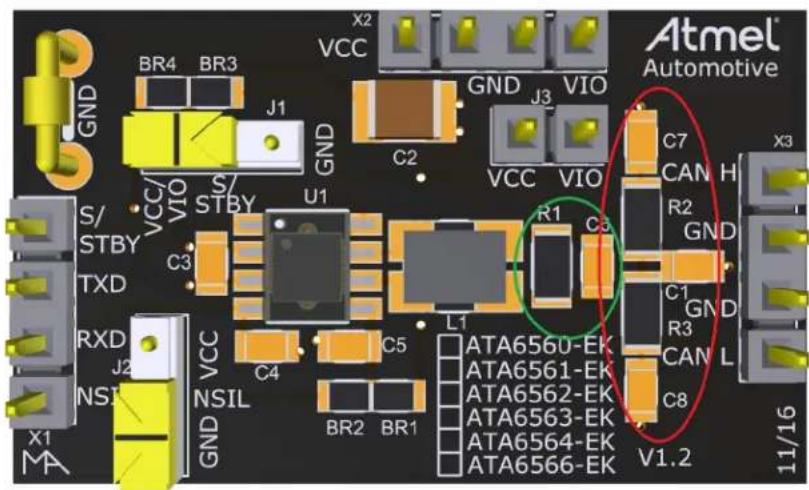
text_image
Atmel Automotive VCC GND V10 CAN H C7 C2 VCC V10 R1 C6 R2 GND C1 GND R3 C5 C4 C3 TXD RXD J2 VSIL X1 MA GN VIN STBY S/ STBY C3 C4 BR2 BR1 ATA6560-EK ATA6561-EK ATA6562-EK ATA6563-EK ATA6564-EK ATA6566-EK V1.2 11/16FIGURE 1-3: ATA6560/1/2/3/4/6 Evaluation Kit.
1.4 CONTENTS OF THE ATA6560/1/2/3/4/6 EVALUATION KIT
This ATA6560/1/2/3/4/6 Evaluation Kit includes:
• ATA6560/1/2/3/4/6 Evaluation Board (ADM00869)
• Important Information Sheet
Chapter 2. Installation and Operation
2.1 DEVELOPMENT KIT
The ATA6560/1/2/3/4/6 Evaluation Kit supports the following features:
- All components necessary to put the ATA6560/1/2/3/4/6 into operation are included
- Placeholders for some optional components for extended functions are included (e.g., common-mode choke)
- All pins are easily accessible
- Footprint for VDFN8 and SOIC8 packages
- Ground coulter clip for easy probe connection during oscilloscope measurement
2.2 FEATURES
• Fully Compliant with ISO 11898-2,-5 and SAE J2962-2
- Low Electromagnetic Emission (EME) and High Electromagnetic Immunity (EMI)
- Communication Speed up to 5 Mbit/s
• Differential Receiver with Wide Common-Mode Range
- Silent Mode (receive only mode, available only for ATA6560, ATA6562 and ATA6564)
- Standby Mode (not for ATA6564)
- Remote Wake-Up Capability via CAN Bus (not for ATA6564)
- Functional Behavior Predictable under All Supply Conditions
• Transceiver Disengages from the Bus When Not Powered-Up
• RXD Recessive Clamping Detection
• High Electrostatic Discharge (ESD) Handling Capability on the Bus Pins
- Bus Pins Protected against Transients in Automotive Environments
• Transmit Data (TXD) Dominant Time-Out Function
- Undervoltage Detection on VCC and VIO Pins
• CANH/CANL Short-Circuit and Overtemperature Protected
2.3 QUICK START
The ATA6560/1/2/3/4/6 Evaluation Kit is shipped including all components, allowing immediate CAN node development.
Connecting an external 5V DC power supply between the terminals VCC and GND puts the IC in one of the three operating modes: Normal, Silent (with ATA6560, ATA6562 and ATA6564 only) and Standby, which can be selected via the STBY and NSIL pins (see Section 3.8 "System Control Pins (STBY, NSIL, S)"). See Table 2-1 for a description of the operating modes under normal supply conditions.
TABLE 2-1: OPERATING MODES
| Mode | Inputs Outputs | |||||
| STBY NSIL | (5) | S^(6) | Pin TXD CAN Driver Pin RXD | |||
| Normal LOW HIGH | (2) | LOW LOW | Dominant LOW | |||
| Standby | LOW HIGH | (2) | LOW HIGH | Recessive HIGH | ||
| HIGH | x^(3) | — | x^(3) | Recessive | Active(4) | |
| Silent LOW | LOW HIGH | x | (3) | Recessive | Active(1) | |
Note 1: LOW if the CAN bus is dominant, HIGH if the CAN bus is recessive.
2: Internally pulled up if not bonded out.
3: Irrelevant.
4: Reflects the bus only for wake-up.
5: Only ATA6560 and ATA6562.
6: Only ATA6564.

text_image
Atmel® Automotive GND BR4 BR3 J1 VCC X2 GND J3 VIO C2 VCC VIO C7 CAN H X3 S/ STBY VCC VIO S/ STBY U1 C3 TXD RXD J2 NSIL VCC C4 C5 L1 R1 C6 C1 GND R3 CAN L C8 V1.2 X1 MA ATA6560-EK ATA6561-EK ATA6562-EK ATA6563-EK ATA6564-EK ATA6566-EK 11/16FIGURE 2-1: Switch Jumpers for Changing the Operating Mode (J2 Available for ATA6560 and ATA6562 only).
2.4 NORMAL MODE
A low level on the STBY pin together with a high level on pins TXD and NSIL (ATA6560 and ATA6562) or a low level on the S pin (ATA6564) selects the Normal mode. In this mode, the transceiver is able to transmit and receive data via the CANH and CANL bus lines. The output driver stage is active and drives data from the TXD input to the CAN bus. The high-speed comparator (HSC) converts the analog data on the bus lines into digital data which is output to the RXD pin. The bus biasing is set to VCC/2 and the undervoltage monitoring of VCC is active.
The slope of the output signals on the bus lines is controlled and optimized in a way that guarantees the lowest possible electromagnetic emission (EME).
To switch the device in normal operating mode, set the STBY pin to low (switch jumper J1 set to the right side) and the NSIL pin (if available) to high (switch jumper J2 set to upper position). For example, for test purposes a signal generator can also be connected to the STBY pin and/or to the NSIL pin (at the pin header X1 on the left side of the board). Therefore the switch jumper J1 and/or J2 should be set to the middle position.
The STBY and the NSIL pins each provide a pull-up resistor to VIO respectively VCC, the S pin a pull-down resistor to GND, thus ensuring defined levels if the pins are open.
Note: The device cannot enter Normal mode as long as the TXD is at GND level.
2.5 SILENT MODE (WITH ATA6560, ATA6562 AND ATA6564 ONLY)
For the ATA6560 and ATA6562, a low level on the NSIL and STBY pins switches the devices into Silent mode. The ATA6564 switches into Silent mode, when a high level is applied to the S pin. This receive-only mode can be used to test the connection of the bus medium. In Silent mode, the ATA6560, ATA6562 and ATA6564 can still receive data from the bus, but the transmitter is disabled and therefore no data can be sent to the CAN bus. The bus pins are released to recessive state. All other IC functions, including the high-speed comparator (HSC), continue to operate as they do in Normal mode. Silent mode can be used to prevent a faulty CAN controller from disrupting all network communications.
2.6 STANDBY MODE (NOT FOR THE ATA6564)
A high level on the STBY pin selects the Standby mode. In this mode, the transceiver is not able to transmit or correctly receive data via the bus lines. The transmitter and the high-speed comparator (HSC) are switched off to reduce current consumption and only the low-power wake-up comparator (WUC) monitors the bus lines for a valid wake-up signal. For the ATA6560 and ATA6561, a signal change on the bus from Recessive to Dominant, followed by a dominant state longer than t_wake , switches the RXD pin to low to signal a wake-up request to the microcontroller.
The ATA6562, ATA6563 and ATA6566 do not wake-up with a single long dominant phase on the bus, they only wake-up when they receive a wake-up pattern (WUP).
The wake-up pattern consists of at least two consecutive dominant bus levels for a duration of at least t_Filter (0.5 s-3.8 s), each separated by a recessive bus level with a duration of at least t_Filter (0.5 s-3.8 s). This filtering helps to avoid spurious wake-up events, which would be triggered by scenarios such as a dominant clamped bus or by a dominant phase due to noise, spikes on the bus, automotive transients or EMI.
In Standby mode, the bus lines are biased to ground to reduce current consumption to a minimum. The wake-up comparator (WUC) monitors the bus lines for a valid wake-up signal. When the RXD pin switches to low to signal a wake-up request, a transition to Normal mode is not triggered until the STBY pin is forced back to low by the microcontroller. A bus dominant time-out timer prevents the device from generating a permanent wake-up request by switching the RXD pin to high.
For the ATA6560 and ATA6562, if the NSIL input pin is set to low in Standby mode, the internal pull-up resistor causes an additional quiescent current from VCC to GND. It is recommended to set the NSIL pin to high in standby mode.
NOTES:
Chapter 3. Hardware Description
3.1 PIN DESCRIPTION
The following sections show and describe the external elements required for some of the pins. See the specific datasheet for more information about this topic.
3.2 POWER SUPPLY
In order to get the development board running, an external stabilized 5V DC power supply has to be connected to the VCC header. The maximum rating for the VCC pin is 5.5V and a higher voltage may cause permanent damage to the device.
3.3 VIO SUPPLY PIN
There are two available device versions, with a different function of pin 5:
- On the ATA6561, ATA6563, ATA6564 and ATA6566, pin 5 is VIO and should be connected to the supply voltage of the connected microcontroller. This adjusts the signal levels of the TXD, RXD, NSIL, S and STBY pins to the I/O levels of the microcontroller. A jumper is implemented on the board (J3) connecting VIO to VCC for test purposes or quick measurements. If the VIO pin has to be supplied with a different voltage, jumper J3 has to be removed and the VIO pin header connected to the second external DC power supply (typically 3.3V).
- On the ATA6560 and ATA6562 without the VIO pin, the VIO input is internally connected to VCC. This sets the signal levels of the TXD, RXD, STBY and NSIL pins to levels compatible with 5V microcontrollers.
3.4 CAN INTERFACE (CANH, CANL, TXD, RXD)
The CAN transceiver is only active when it is in Normal mode. In Silent mode the transmitter is switched off and the ATA6560, ATA6562 and ATA6564 are in receive-only mode. In Standby mode the transceiver is completely switched off and no communication is possible. Only a low power wake-up comparator (WUC) is active in order to reflect the bus for a wake-up (not with the ATA6564).
3.5 CANH AND CANL PINS
The CANH and CANL pins are the interface to the bus network. Nodes connected to the bus end must show a differential termination, which is approximately equal to the characteristic impedance of the bus line in order to suppress signal reflection. Instead of a one-resistor termination it is highly recommended to use a so-called split termination. EMC measurements have shown that the split termination is able to significantly improve the signal symmetry between CANH and CANL, thus reducing the emission. Basically each of the two termination resistors is split into two resistors of equal value, i.e., two resistors of 60Ω (or 62Ω) (R2 and R3) instead of one resistor of 120Ω. The special characteristic of this approach is that the common-mode signal, available at the center tap of the termination, is terminated to ground via a capacitor. The recommended value for this capacitor is in the range of 4.7 nF to 47 nF (C7).
As the symmetry of the two signal lines is crucial for the emission performance of the system, the matching tolerance of the two termination resistors should be as low as possible (< 1% is desirable).
In addition, loading the CANH and CANL pins each with a capacitor of about 100 pF close to the connector of the ECU (there are placeholders on the PCB for the capacitors C7 and C8) is recommended. The main reason for doing this is to increase the robustness to automotive transients and ESD. The matching tolerance of the two capacitors should be as low as possible.
OEM specifications may require dedicated circuits. Refer to the corresponding OEM specifications for specific details.
The footprint for an optional common-mode choke, to improve EMC performance, is implemented (L1).
Placeholders (R1, C6 and C4) are implemented on the board for timing measurements.
3.6 TXD INPUT PIN
The signal sent to the TXD input pin controls the state of the CANH/CANL outputs. An internal pull-up resistor to VIO is implemented. The TXD input pin must be pulled to ground in order to drive the CAN bus into dominant state.
An internal timer prevents the bus lines from being driven permanently into the dominant state. If TXD is forced to low longer than t_to(DOM)TXD > 3 ms, the transceiver internally switches the TXD state to high and the CAN bus driver is switched to the recessive state. This feature is used to prevent a single faulty node (for example with a short to ground at the TXD pin) from paralyzing communication on the entire CAN bus the faulty node is connected to.
3.7 RXD OUTPUT PIN
This pin reports the state of the CAN bus to the microcontroller. CAN high (recessive state) is reported by a high level at RXD; CAN low (dominant state) is reported by a low level at RXD. The RXD output is a push-pull stage and is short-circuit protected.
3.8 SYSTEM CONTROL PINS (STBY, NSIL, S)
These input pins are used for mode control. They are typically directly connected to an output port pin of a microcontroller. The ATA6560/1/2/3/4/6 supports three operating modes: Normal, Silent (only with the ATA6560, ATA6562 and ATA6564) and Standby (not with the ATA6564), which can be selected via the STBY, S and NSIL pins. See Table2-1 for a description of the operating modes under normal supply conditions.
The STBY and the NSIL pins each provide a pull-up resistor to VIO, respectively VCC. The S pin of the ATA6564 provides a pull-down resistor to GND, thus ensuring defined levels if the pins are open.
The operating mode can be easily changed via the on-board switch jumpers (switch jumper J1 for STBY/S pin control and switch jumper J2 for NSIL pin control). If desired, this can be done also via an external signal generator, but therefore the switch jumper J1 and/or J2 should be set to the middle position.
Chapter 4. Applications
4.1 TYPICAL APPLICATION CIRCUITS
Figure 4-1 and Figure 4-2 illustrate typical circuit examples using the ATA6560/1/2/3/4/6 devices. The application examples assume either a 5V or a 3V supplied host microcontroller. In each example there is a dedicated 5V regulator supplying the ATA6560/1/2/3/4/6 transceiver on its VCC supply pin (necessary for proper CAN transmit capability). Depending on which device is soldered on the board, all corresponding components required are mounted on the board.

text_image
VDD Microcontroller GND STBY/S(2) TXD RXD VIO VCC 100nF 100nF 22µF(1) 3.3V/ 12V 5V/ 12V BAT ATA6561/3/4/6 CANH CANL CANL CANH CANL GNDNote 1: The size of this capacitor depends on the used external voltage regulator.
2: S pin only for the ATA6564.
FIGURE 4-1: Typical Application Circuit ATA6561/3/4/6 – the VIO Pin Allows Direct Interfacing to Microcontrollers with Supply Voltages Down to 2.8V.
text_image
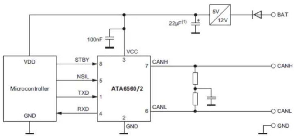
VDD Microcontroller GND STBY NSIL TXD RXD VCC 3 8 5 1 4 2 7 6 VCC 22µF(1) + 5V 12V BAT CANH CANL CANL CANH CANL GNDNote 1: The size of this capacitor depends on the used external voltage regulator.
FIGURE 4-2: Typical Application Circuit ATA6560 and ATA6562 – the NSIL Pin Allows the Device to be Switched to Receive-Only Mode, Only One LDO is Necessary with a 5V Microcontroller.
Chapter 5. Test Setups and Measurements
5.1 TIMING MEASUREMENTS
The required components on the basic application board can be found below. A two-channel, or optimally, a four-channel oscilloscope is sufficient to measure the timing characteristics of the ATA6560/1/2/3/4/6. The transmit data signal TXD can be generated by any signal generator that is capable of delivering a rectangular or pulse signal with 3.3V to 5V amplitude, referred to GND. The characteristics of TXD, RXD and the CANH, CANL signals can be examined.

text_image
+5V + 47μF 100nF 5 3 VIO/NSIL VCC TXD CANH RXD CANL GND STBY/S 2 8 1 7 100pF RL 4 6 15pFFIGURE 5-1: Test Setup for Timing Measurements.
text_image
Atmel® Automotive GND BR4 BR3 J1 VCC X2 GND J3 VIO C2 VCC VIO C7 CAN H S/ STBY STBY U1 R1 C3 TXD C3 C1 GND RXD J2 NSIL VCC C4 C5 ATA6560-EK ATA6561-EK ATA6562-EK ATA6563-EK ATA6564-EK ATA6566-EK V1.2 X1 MA 11/16FIGURE 5-2: Components to be Removed (Red) or Replaced (Green) for the Timing Measurement Setup.
The footprint for an optional common-mode choke (L1) is implemented on the development board. This common-mode choke (L1) is per default replaced by two 0Ω resistors.
Instead of a one-resistor termination, it is highly recommended to use the commonly used so-called split termination, which is per default assembled. EMC measurements have shown that the split termination is able to significantly improve the signal symmetry between CANH and CANL, thus reducing emissions. Basically the termination is split into two resistors of equal value (R2 = R3 = 62Ω) and a capacitor (C1) to GND at the center tap, which represents one of the two usual bus end terminations. The special characteristic of this approach is that the common-mode signal, available at the center tap of the two resistors, is terminated to ground via the capacitor C1. The recommended value for this capacitor C1 is in the range of 4.7 nF to 47 nF (4.7 nF assembled per default).
As the symmetry of the two signal lines is crucial for the emission performance of the system, the matching tolerance of the two termination resistors R1 and R2 should be as low as possible (< 1% is desirable).
Additionally placeholders are implemented on the board for timing measurements (R1, C6 and C4). If a function generator is connected to the TXD header, it can be adjusted to output a rectangular signal up to a frequency corresponding to the maximum data rate of the final application. Pay attention that its output signal levels are in the appropriate range particularly that no negative voltage occurs. The function generator can be replaced by a dedicated data generator in order to form a better approach to the desired application. The high-impedance inputs of the oscilloscope can be connected directly - however it's advantageous to use probes, so that the signals are not noticeably affected by the capacitance of the coaxial cable.

other
| Signal | High State | Low State | |--------|------------|-----------| | TXD | HIGH | LOW | | CANH | CANH | CANH | | CANL | CANL | CANL | | V_O(dif) (bus) | Dominant | 0.9V | | RXD | Dominant | 0.5V | | RXD | High | 0.7V_IO | | t_d(TXD-busdom) | Low | t_d(TXD-RXD) | | t_d(TXD-busrec) | Low | t_d(TXD-RXD) | | t_d(TXD-busrec) | High | 0.7V_IO | | t_D(TXD-busrec) | High | 0.5V |FIGURE 5-3: Timing Diagram for High Speed CAN Bus.
line
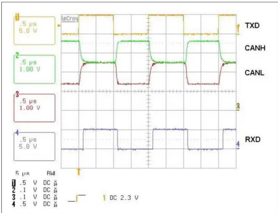
| Component | Time (μs) | Voltage (V) | |-----------|-----------|-------------| | TXD | 5 | 5.8 | | CANH | 1 | 1.00 | | CANL | 1 | 1.00 | | RXD | 5 | 5.8 |FIGURE 5-4: Measurement of the TXD, CANH, CANL and RXD Signal at a Data Rate of 1 Mbit/s.
Figure 5-4 shows the typical bus line signals for a 0-1 bit sequence at a data rate of 1 Mbit/s and VCC = VIO = 5V. The excellent symmetry of the CANH and CANL signals ensures superior EMC performance.
5.2 MEASUREMENT HINTS
5.2.1 Passive Behavior
In many applications, some transceivers can become unpowered (e.g., clamp-15 nodes) while other transceivers are continuously supplied (e.g., clamp-30 nodes). In such networks, the ATA6560/1/2/3/4/6 is favored for partially unpowered applications because of its excellent passive behavior to the bus when the VCC supply is switched off. In addition, the ATA6560/1/2/3/4/6 is protected against reverse currents via the TXD, RXD, NSIL, S and STBY pins. There is no backward current via those pins if the accompanying microcontroller continues to be supplied.
5.2.2 Optional Circuitry at CANH and CANL
The EMC performance of the ATA6560/1/2/3/4/6 has been optimized for the use of CAN termination without a common-mode choke. The excellent output stage symmetry allows use without chokes. If, however, system performance is still not sufficient, there is the option of using additional measures such as common-mode chokes (a footprint for a common-mode choke is implemented at the ATA6560/1/2/3/4/6 Evaluation Kit), capacitors, and ESD clamping diodes.
5.2.2.1 COMMON-MODE CHOKE
Note: If any critical measurements on EMI (electromagnetic interference) performance, such as electromagnetic immunity or electromagnetic emission, are to be taken, Microchip recommends a dedicated board with a highly symmetrical layout for the bus lines and ground vias at each connection to the ground plane. For investigations on complete links such as bit error measurements, a test board with at least two transceivers is required in any case.
A common-mode choke provides high impedance for common-mode signals and low impedance for differential signals. Because of this, common-mode signals produced by RF noise and/or by non-perfect transceiver driver symmetry are effectively reduced while passing the choke. In fact, a common-mode choke helps to reduce emission and to improve immunity against common-mode disturbances. Earlier transceiver devices usually needed a common-mode choke to comply with stringent emission and immunity requirements of the automotive industry when using unshielded twisted-pair cables. The ATA6560/1/2/3/4/6 makes it possible to build in-vehicle bus systems without chokes. Whether a choke is needed or not ultimately depends on the specific system implementation such as the wiring harness and the symmetry of the two bus lines (matching tolerances of resistors and capacitors). Besides the RF noise reduction, the stray inductance (non-coupled portion of inductance) may establish a resonant circuit together with pin capacitance. This can result in unwanted oscillations between the bus pins and the choke both with differential and common-mode signals as well as result in extra emission around the resonant frequency. To avoid oscillations of this kind, it is highly recommended to use only chokes with a stray inductance lower than 500 nH. Bifilar wound chokes typically show an even lower stray inductance. The choke should be placed nearest to the transceiver bus pins.
The use of common-mode chokes in CAN systems might cause extremely high transient voltages at the bus pins of the transceiver. These transients are generated by the change in current through the inductance of the common-mode chokes if the CAN bus is shorted to DC voltages. The actual transients that might be generated are highly dependent on the common-mode type and value, but also depend on the CAN system architecture, termination, components, location and the severity of the short circuit.
For systems where common-mode chokes are required, care should be used in the choice of the common-mode choke and the system circuit to avoid the introduction of severe transients during DC short-circuit conditions on the bus.
The best methods to avoid transients generated from common-mode chokes during CAN bus line shorts to DC voltages are:
- Remove common-mode chokes from systems, where applicable
- Move transient suppression circuits between the common-mode choke and the CAN bus pins on the transceiver
- Choose a dedicated common-mode choke and a CAN termination scheme to minimize transients
5.2.2.2 CAPACITORS
Matched capacitors (in pairs) at CANH and CANL to GND are frequently used to enhance immunity against electromagnetic interferences. Along with the impedance of corresponding noise sources (RF), capacitors at CANH and CANL to GND form an RC low-pass filter. Regarding immunity, the capacitor value should be as large as possible to achieve a low corner frequency. The overall capacitive load and impedance of the output stage establish an RC low-pass filter for the data signals. The associated corner
frequency must be well above the data transmission frequency. This results in a limit for the capacitor value depending on the number of nodes and the data transmission frequency. Notice that capacitors increase the signal loop delay due to longer rise and fall times. Due to these time reductions, bit timing requirements, especially at 1 Mbit/s, call for a value lower than 100 pF (see also SAE J2284 and ISO 11898). At a bit rate of 125 kBit/s the capacitor value should not exceed 470 pF. Typically, the capacitors are placed between the common-mode choke (if applied at all) and the ESD clamping diodes
5.2.2.3 ESD PROTECTION
The ATA6560/1/2/3/4/6 is designed to withstand ESD pulses of up to 8 kV according to the human body model at the CANH and CANL bus pins and thus typically does not need any additional external protection methods. Nevertheless, if a higher protection level is required, external clamping devices can be applied to the CANH and CANL lines.
Care must be taken when selecting the right protection devices. The transient protectors must be fast enough to clamp the transient voltages. In addition, their capacitance must be considered. If the capacitance is too high, it can work together with the choke's inductance and cause ringing on the bus signals. Although this ringing does not corrupt the CAN signals, it might show up as electromagnetic emission at higher frequencies.
NOTES:
Appendix A. Schematic and Layouts
A.1 INTRODUCTION
This appendix contains the following schematic and layouts for the ATA6560/1/2/3/4/6 Evaluation Kit:
- Board – Schematic
- Board – Top Silk
- Board – Top Copper and Silk
- Board – Top Copper
- Board – Bottom Copper
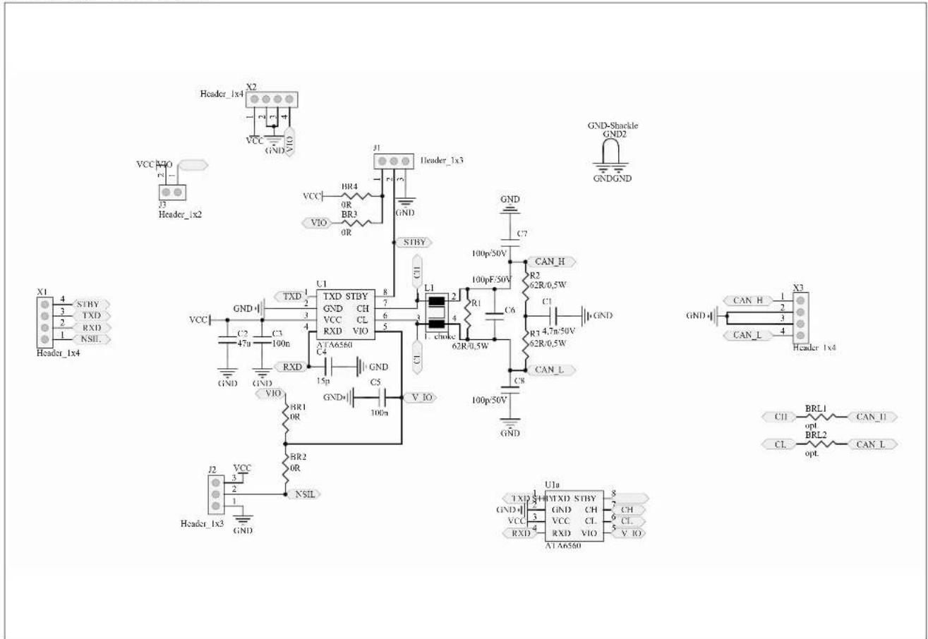
A.2 BOARD - SCHEMATIC
text_image
Header_1x4 X2 VCC GND VIO J3 Header_1x2 VCC NVO R1 HR4 0R BR3 0R VTO VCC HR4 0R BR3 0R J1 Header_1x3 GND-Shackle GND2 GNDGND C7 STBY U1 TXD STBY GND CH VCC CL RXD VIO XTA6580 C4 RXD 15p C5 V_IO L1 2 100p/50V CAN_H R2 62R/0.5W C6 R3 4.7n/50V 62R/0.5W CAN_L C8 100p/50V GND U1a TXD SHOMXD STBY 3 GND GND CH CH VCC VCC CL CL RXD RXD VIO V_IO XTA6580 C11 BRL1 CAN_II CL BRL2 CAN_L X1 4 STBY 3 TXD RXD NSIL Header_1x4A.3 BOARD - TOP SILK
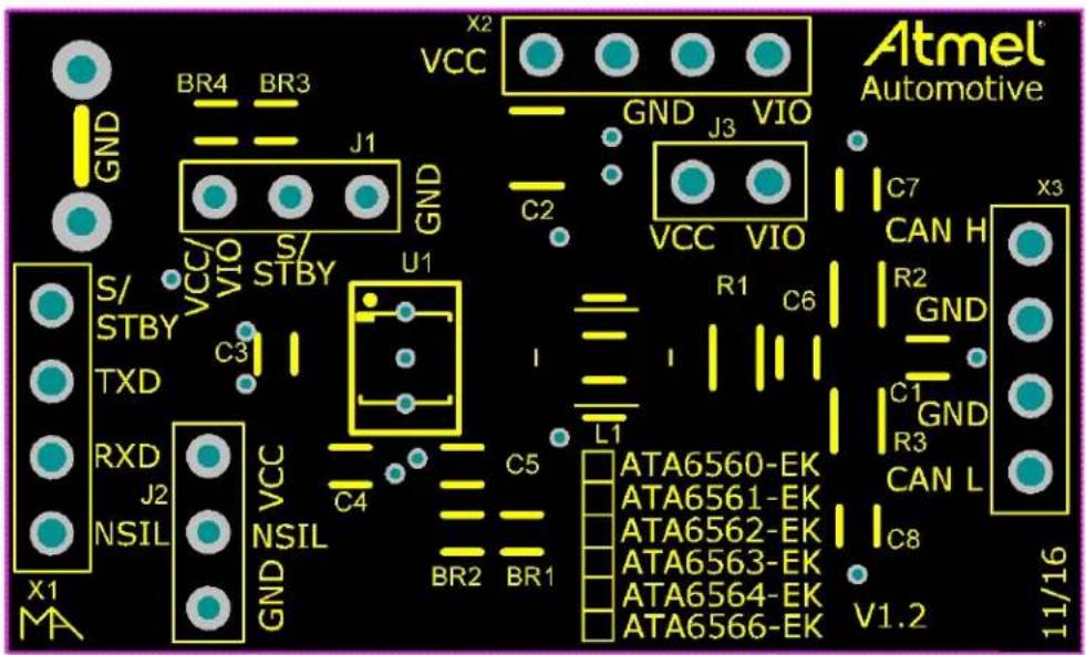
text_image
Atmel Automotive X2 VCC GND J3 VIO C7 CAN H X3 BR4 BR3 GND J1 GND VCC VIO S/ STBY S/ STBY U1 C2 VCC VIO R1 C6 I L1 C5 C4 C3 RXD J2 NSIL VCC NSIL GND BR2 BR1 ATA6560-EK ATA6561-EK ATA6562-EK ATA6563-EK ATA6564-EK ATA6566-EK C8 V1.2 11/16 X1 MAA.4 BOARD – TOP COPPER AND SILK

text_image
Atmel Automotive GND BR4 BR3 J1 GND VCC X2 GND J3 VIO C2 VCC VIO C7 CAN H X3 S/ STBY STBY U1 C3 R1 C6 R2 GND TXD C4 NISPL1 NISPL2 L1 C5 C1 GND RXD J2 NSIL VCC GND NSIL BR2 BR1 ATA6560-EK ATA6561-EK ATA6562-EK ATA6563-EK ATA6564-EK ATA6566-EK C8 V1.2 X1 MA 11/16A.5 BOARD - TOP COPPER

text_image
Circuit diagram with red and teal components labeled with component identifiers such as 'NeBPL1' and 'NeBPL2'A.6 BOARD - BOTTOM COPPER
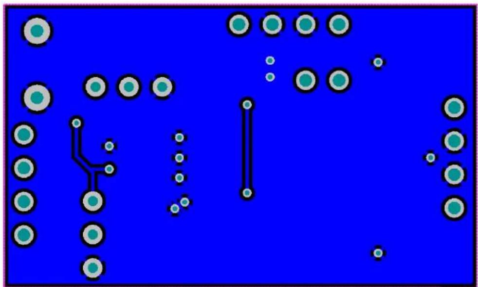
natural_image
Pure electrical circuit lines without any symbolsAppendix B. Bill of Materials (BOM)
TABLE B-1: BILL OF MATERIALS (BOM) FOR ATA6560 AND ATA6562 (PIN 5 = NSIL)
| Part | Description | Part | Size | Part |
| X1 | Header 1 x 4 | 1 x 4 2.54 mm | Header 1 x 4 | |
| X2 | Header 1 x 2 | 1 x 2 2.54 mm | Header 1 x 2 | |
| X3 | Header 1 x 4 | 1 x 4 2.54 mm | Header 1 x 4 | |
| J1 | PCB jumper switch | 1 x 3 2.54 mm | PCB jumper switch1 x 3 2.54 mm | |
| J2 | PCB jumper switch | 1 x 3 2.54 mm | PCB jumper switch1 x 3 2.54 mm | |
| C1 | Capacitor | SMD 0805 | 4.7 nF/50V | |
| C2 | Capacitor | SMD 1210 | 47 μF/10V | |
| C3 | Capacitor | SMD 0805 | 100 nF | |
| GND-shackle | Measuring bracket | GND-shackle | GND2 | |
| R2 | resistor | SMD 1206 | 62Ω/0.5W | |
| R3 | resistor | SMD 1206 | 62Ω/0.5W | |
| L1 | Common mode choke | EPCOS B82799 | EPCOS B827990Ω resistor 0805 between term. 1 and 2 and between term. 3 and 4 | |
| BR2 | 0Ω resistor | SMD 0805 | 0Ω | |
| BR4 | 0Ω resistor | SMD 0805 | 0Ω | |
| IC - SOIC8 | CAN- transceiver | SOIC8 | ATA6560-GAQWATA6562-GAQW1 | |
| IC - VDFN8 | CAN- transceiver | VDFN8 | ATA6560-GBQWATA6562-GBQW1 |
TABLE B-2: BILL OF MATERIALS (BOM) FOR ATA6561, ATA6563 AND ATA6566 (PIN 5 = VIO)
| Part | Description | Part | Size | Part |
| X1 | Header 1 x 3 | 1 x 3 2.54 mm | Header 1 x 3 | |
| X2 | Header 1 x 4 | 1 x 4 2.54 mm | Header 1 x 4 | |
| X3 | Header 1 x 4 | 1 x 4 2.54 mm | Header 1 x 4 | |
| J1 | PCB jumper switch | 1 x 3 2.54 mm | PCB jumper switch1 x 3 2.54 mm | |
| J3 | Header 1 x 2 | 1 x 2 2.54 mm | Header 1 x 2 | |
| C1 | Capacitor | SMD 0805 | 4.7 nF/50V | |
| C2 | Capacitor | SMD 1210 | 47 μF/10V | |
| C3 | Capacitor | SMD 0805 | 100 nF | |
| C5 | Capacitor | SMD 0805 | 100 nF | |
| GND-shackle | Measuring bracket | GND-shackle | GND2 | |
| R2 | resistor | SMD 1206 | 62Ω/0.5W | |
| R3 | resistor | SMD 1206 | 62Ω/0.5W | |
| L1 | Common mode choke | EPCOS B82799 | EPCOS B827990Ω resistor 0805 between term. 1 and 2 and between term. 3 and 4 | |
| BR1 | 0Ω resistor | SMD 0805 | 0Ω | |
| BR3 | 0Ω resistor | SMD 0805 | 0Ω | |
| IC - SOIC8 | CAN- transceiver | SOIC8 | ATA6561-GAQWATA6563-GAQW1ATA6566-GAQW1 | |
| IC - VDFN8 | CAN- transceiver | VDFN8 | ATA6561-GBQWATA6563-GAQW1ATA6566-GBQW1 |
TABLE B-3: BILL OF MATERIALS (BOM) FOR ATA6564 (PIN 5 = VIO, PIN 8 = S)
| Part | Description | Part | Size | Part |
| X1 | Header 1 x 3 | 1 x 3 2.54 mm | Header 1 x 3 | |
| X2 | Header 1 x 4 | 1 x 4 2.54 mm | Header 1 x 4 | |
| X3 | Header 1 x 4 | 1 x 4 2.54 mm | Header 1 x 4 | |
| J1 | PCB jumper switch | 1 x 3 2.54 mm | PCB jumper switch1 x 3 2.54 mm | |
| J3 | Header 1 x 2 | 1 x 2 2.54 mm | Header 1 x 2 | |
| C1 Capacitor | SMD 0805 | 4.7 nF/50V | ||
| C2 Capacitor | SMD | 1210 | 47 μF | 10V |
| C3 | Capacitor | SMD 0805 | 100 nF | |
| C5 Capacitor | SMD 0805 | 100 nF | ||
| GND-shackle | Measuring bracket | GND-shackle | GND2 | |
| R2 | resistor | SMD 1206 | 62Ω/0.5W | |
| R3 | resistor | SMD 1206 | 62Ω/0.5W | |
| L1 | Common mode choke | EPCOS B82799 | EPCOS B827990Ω resistor 0805 between term. 1 and 2 and between term. 3 and 4 | |
| BR1 | 0Ω resistor | SMD 0805 | 0Ω | |
| BR3 | 0Ω resistor | SMD 0805 | 0Ω | |
| IC - SOIC8 | CAN- transceiver | SOIC8 | ATA6564-GAQW1 | |
| IC - VDFN8 | CAN- transceiver | VDFN8 | ATA6564-GBQW1 |
NOTES:
Worldwide Sales and Service
AMERICAS
Corporate Office
2355 West Chandler Blvd.
Chandler, AZ 85224-6199
Tel: 480-792-7200
Fax: 480-792-7277
Technical Support:
http://www.microchip.com/
support
Web Address:
www.microchip.com
Atlanta
Duluth, GA
Tel: 678-957-9614
Fax: 678-957-1455
Austin, TX
Tel: 512-257-3370
Boston
Westborough, MA
Tel: 774-760-0087
Fax: 774-760-0088
Chicago
Itasca, IL
Tel: 630-285-0071
Fax: 630-285-0075
Dallas
Addison, TX
Tel: 972-818-7423
Fax: 972-818-2924
Detroit
Novi, MI
Tel: 248-848-4000
Houston, TX
Tel: 281-894-5983
Indianapolis
Noblesville, IN
Tel: 317-773-8323
Fax: 317-773-5453
Tel: 317-536-2380
Los Angeles
Mission Viejo, CA
Tel: 949-462-9523
Fax: 949-462-9608
Tel: 951-273-7800
Raleigh, NC
Tel: 919-844-7510
New York, NY
Tel: 631-435-6000
San Jose, CA
Tel: 408-735-9110
Tel: 408-436-4270
Canada - Toronto
Tel: 905-695-1980
Fax: 905-695-2078
ASIA/PACIFIC
Asia Pacific Office
Suites 3707-14, 37th Floor
Tower 6, The Gateway
Harbour City, Kowloon
Hong Kong
Tel: 852-2943-5100
Fax: 852-2401-3431
Australia - Sydney
Tel: 61-2-9868-6733
Fax: 61-2-9868-6755
China - Beijing
Tel: 86-10-8569-7000
Fax: 86-10-8528-2104
China - Chengdu
Tel: 86-28-8665-551
Fax: 86-28-8665-7889
China - Chongqing
Tel: 86-23-8980-9588
Fax: 86-23-8980-9500
China - Dongguan
Tel: 86-769-8702-9880
China - Guangzhou
Tel: 86-20-8755-8029
China - Hangzhou
Tel: 86-571-8792-8115
Fax: 86-571-8792-8116
China - Hong Kong SAR
Tel: 852-2943-5100
Fax: 852-2401-3431
China - Nanjing
Tel: 86-25-8473-2460
Fax: 86-25-8473-2470
China - Qingdao
Tel: 86-532-8502-7355
Fax: 86-532-8502-7205
China - Shanghai
Tel: 86-21-3326-8000
Fax: 86-21-3326-8021
China - Shenyang
Tel: 86-24-2334-2829
Fax: 86-24-2334-2393
China - Shenzhen
Tel: 86-755-8864-2200
Fax: 86-755-8203-1760
China - Wuhan
Tel: 86-27-5980-5300
Fax: 86-27-5980-5118
China - Xian
Tel: 86-29-8833-7252
Fax: 86-29-8833-7256
ASIA/PACIFIC
China - Xiamen
Tel: 86-592-2388138
Fax: 86-592-2388130
China - Zhuhai
Tel: 86-756-3210040
Fax: 86-756-3210049
India - Bangalore
Tel: 91-80-3090-4444
Fax: 91-80-3090-4123
India - New Delhi
Tel: 91-11-4160-8631
Fax: 91-11-4160-8632
India - Pune
Tel: 91-20-3019-1500
Japan - Osaka
Tel: 81-6-6152-7160
Fax: 81-6-6152-9310
Japan - Tokyo
Tel: 81-3-6880-3770
Fax: 81-3-6880-3771
Korea - Daegu
Tel: 82-53-744-4301
Fax: 82-53-744-4302
Korea - Seoul
Tel: 82-2-554-7200
Fax: 82-2-558-5932 or
82-2-558-5934
Malaysia - Kuala Lumpur
Tel: 60-3-6201-9857
Fax: 60-3-6201-9859
Malaysia - Penang
Tel: 60-4-227-8870
Fax: 60-4-227-4068
Philippines - Manila
Tel: 63-2-634-9065
Fax: 63-2-634-9069
Singapore
Tel: 65-6334-8870
Fax: 65-6334-8850
Taiwan - Hsin Chu
Tel: 886-3-5778-366
Fax: 886-3-5770-955
Taiwan - Kaohsiung
Tel: 886-7-213-7830
Taiwan - Taipei
Tel: 886-2-2508-8600
Fax: 886-2-2508-0102
Thailand - Bangkok
Tel: 66-2-694-1351
Fax: 66-2-694-1350
EUROPE
Austria - Wels
Tel: 43-7242-2244-39
Fax: 43-7242-2244-393
Denmark - Copenhagen
Tel: 45-4450-2828
Fax: 45-4485-2829
Finland - Espoo
Tel: 358-9-4520-820
France - Paris
Tel: 33-1-69-53-63-20
Fax: 33-1-69-30-90-79
France - Saint Cloud
Tel: 33-1-30-60-70-00
Germany - Garching
Tel: 49-8931-9700
Germany - Haan
Tel: 49-2129-3766400
Germany - Heilbronn
Tel: 49-7131-67-3636
Germany - Karlsruhe
Tel: 49-721-625370
Germany - Munich
Tel: 49-89-627-144-0
Fax: 49-89-627-144-44
Germany - Rosenheim
Tel: 49-8031-354-560
Israel - Ra'anana
Tel: 972-9-744-7705
Italy - Milan
Tel: 39-0331-742611
Fax: 39-0331-466781
Italy - Padova
Tel: 39-049-7625286
Netherlands - Drunen
Tel: 31-416-690399
Fax: 31-416-690340
Norway - Trondheim
Tel: 47-7289-7561
Poland - Warsaw
Tel: 48-22-3325737
Romania - Bucharest
Tel: 40-21-407-87-50
Spain - Madrid
Tel: 34-91-708-08-90
Fax: 34-91-708-08-91
Sweden - Gothenberg
Tel: 46-31-704-60-40
Sweden - Stockholm
Tel: 46-8-5090-4654
UK - Wokingham
Tel: 44-118-921-5800
Fax: 44-118-921-5820