125-TBL8804 - Security Camera Geovision - Free user manual and instructions
Find the device manual for free 125-TBL8804 Geovision in PDF.

User questions about 125-TBL8804 Geovision
0 question about this device. Answer the ones you know or ask your own.
Ask a new question about this device
Download the instructions for your Security Camera in PDF format for free! Find your manual 125-TBL8804 - Geovision and take your electronic device back in hand. On this page are published all the documents necessary for the use of your device. 125-TBL8804 by Geovision.
USER MANUAL 125-TBL8804 Geovision
natural_image
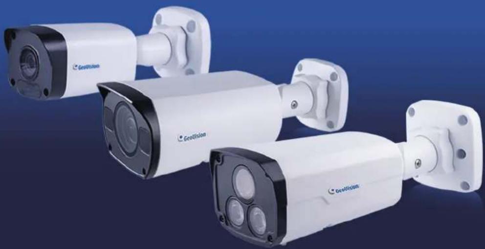
Exterior view of multiple GeoVision security cameras against a blue background (no text or symbols visible on the cameras themselves)• GV-ABL / TBL Series
• GV-ADR / TDR Series
• GV-AVD / TVD Series
GV-BLFC5800
GV-EBD Series
GV-EBFC5800
GV-FER5702
GV-PTZ5810-IR
GV-TFD Series
natural_image
Three white GEUVision security cameras with black and white modules, displayed against a blue background (no text or symbols visible on the devices themselves)© 2022 GeoVision, Inc. All rights reserved.
Under the copyright laws, this manual may not be copied, in whole or in part, without the written consent of GeoVision.
Every effort has been made to ensure that the information in this manual is accurate. GeoVision, Inc. makes no expressed or implied warranty of any kind and assumes no responsibility for errors or omissions. No liability is assumed for incidental or consequential damages arising from the use of the information or products contained herein. Features and specifications are subject to change without notice.
GeoVision, Inc.
9F, No. 246, Sec. 1, Neihu Rd.,
Neihu District, Taipei, Taiwan
Trademarks used in this manual: GeoVision, the GeoVision logo and GV series products are trademarks of GeoVision, Inc. Windows is the registered trademark of Microsoft Corporation.
May 2022
Scan the following QR codes for product warranty and technical support policy:

text_image
QR code image containing encoded data, no visible human-readable text
text_image
QR code image containing encoded data, no visible human-readable text[Warranty] [Technical Support Policy]
Preface
Welcome to the GV-IP Camera User's Manual.
The features described in the manual vary among camera models and versions. Some features may not be available in your camera.
This Manual is designed for the following models:
| Model | Model Number |
| IR Eyeball Dome | GV-EBD2702 / 2704 |
| GV-EBD4700 / 4701 / 4704 / 4711 / 4712 / 4813 | |
| GV-EBD8700 / 8711 / 8800 / 8813 | |
| GV-EBFC5800 | |
| Bullet IP Camera | GV-ABL2701 Series / 2702 / 2703 Series |
| GV-ABL4701 Series / 4703 / 4711 / 4712 | |
| GV-ABL8712 | |
| GV-TBL2703 Series / 2705 / 4700 / 4703 / 4705 / 4710 / 4711 / 4810 | |
| GV-TBL8710 / 8804 / 8810 | |
| GV-BLFC5800 | |
| Mini Fixed IP Dome | GV-TFD4700 / 4800 |
| Mini Fixed Rugged IP Dome | GV-ADR2701 / 2702 |
| GV-ADR4701 / 4702 | |
| GV-TDR2700 / 2702 / 2704 | |
| GV-TDR4700 Series / 4702 Series / 4703 Series / 4704 Series / 4803 Series | |
| GV-TDR8805 | |
| Vandal Proof IP Dome | GV-AVD2700 |
| GV-AVD4710 | |
| GV-AVD8710 | |
| GV-TVD4700 / 4710 / 4711 / 4810 | |
| GV-TVD8710 / 8810 | |
| IR Fisheye Rugged IP Camera | GV-FER5702 |
| IR Mini PTZ Camera | GV-PTZ5810-IR |
Contents
Naming Definition......vi
Note for Connecting to GV-VMS / DVR / NVR......vii
Note for Installing Camera Outdoor ......vii
Note for Powering the Camera......vii
Chapter 1 Introduction ......1
1.1 GV-EBD Series and GV-EBFC5800 1
1.1.1 Packing List.... 2
1.1.2 Optional Accessories 2
1.1.3 Overview....4
1.1.3.1 GV-EBD2702 / 2704 / 4700 / 4701 / 4704 / 8700 / 8800 and
GV-ENFC5800 .... 4
1.1.3.2 GV-EBD4711 / 4712 / 4813 / 8711 / 8813 5
1.1.4 Installation....6
1.1.4.1 GV-EBD2702 / 2704 / 4700 / 4701 / 4704 / 8700 / 8800 and GV-EBFC5800 Standard Installation....6
1.1.4.2 GV-EBD4711 / 4712 / 4813 / 8711 / 8813 Standard Installation ... 9
1.1.5 Optional Installation....12
1.1.5.1 GV-Mount211P....12
1.1.5.2 GV-Mount212P....17
1.1.5.3 GV-Mount420 + GV-Mount211P....21
1.1.5.4 GV-Mount212P + GV-Mount107....24
1.2 GV-ABL / TBL Series & GV-BLFC5800....26
1.2.1 Packing List....27
1.2.2 Optional Accessories ......27
1.2.3 Overview....29
1.2.3.1 GV-ABL2701 / 2703 / 4701 / 4703 & TBL2703 / 2705 / 4703.....29
1.2.3.2 GV-ABL2702 / 4711 / 4712 / 8712, TBL4700 / 4705 / 4710 / 4711 / 8710 / 8804 / 8810, and BLFC5800 ....30
1.2.4 Installation....31
1.2.5 Optional Installation....34
1.2.5.1 GV-Mount502....36
1.2.5.2 GV-Mount503....38
1.2.5.3 GV-Mount420 + GV-Mount503....40
1.2.5.4 GV-Mount504 42
1.3 GV-ADR / TDR Series 44
1.3.1 Packing List....46
1.3.2 Optional Accessories 46
1.3.3 Overview....49
1.3.4 Installation....50
1.3.5 Optional Installation 53
1.3.5.1 GV-Mount211P 53
1.4 GV-AVD / TVD Series....57
1.4.1 Packing List....58
1.4.1.1 GV-TVD4711....58
1.4.1.2 GV-AVD / TVD Series....59
1.4.2 Optional Accessories 60
1.4.3 Overview....62
1.4.3.1 GV-AVD2700 / 4710 / 8710, GV-TVD4700 / 4710 / 4810 / 8710 /
8810....62
1.4.3.2 GV-TVD4711....63
1.4.4 Installation....64
1.4.4.1 GV-AVD2700 / 4710 / 8710, GV-TVD4700 / 4710 / 4810 / 8710 /
8810....64
1.4.4.2 GV-TVD4711....66
1.4.5 Optional Installation....67
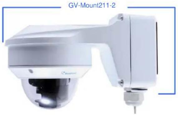
1.4.5.1 GV-Mount211-2....68
1.4.5.2 GV-Mount212-2....70
1.4.5.3 GV-Mount420 + GV-Mount211-2....73
1.4.5.4 GV-Mount606....74
1.5 GV-TFD Series 76
1.5.1 Packing List....76
1.5.2 Optional Accessories 77
1.5.3 Overview....78
1.5.3.1 GV-TFD4700 / 4800....78
1.5.4 Installation....79
1.5.4.1 GV-TFD4700 / 4800....79
1.5.5 Optional Installation....80
1.6 GV-FER5702....81
1.6.1 Packing List....81
1.6.2 Optional Accessories....82
1.6.3 Overview....83
1.6.3.1 GV-FER5702....83
1.6.4 Installation 84
1.6.5 Optional Installation 86
1.7 GV-PTZ5810-IR....87
1.7.1 Packing List 87
1.7.2 Optional Accessories 88
1.7.3 Overview....89
1.7.3.1 GV-PTZ5810-IR 89
1.7.4 Installation 90
1.7.5 Optional Installation 92
1.8 System Requirements....93
1.9 Waterproofing the Cable 94
Chapter 2 Accessing the Camera....96
2.1 Installing on a Network....96
2.1.1 Looking up the Dynamic IP Address and Logging In....97
2.1.2 Configuring the IP Address 98
2.2 Accessing Live View....99
2.2.1 Digital Zoom....101
2.2.2 Start Recording....101
2.3 PTZ Control Panel 102
2.3.1 Accessing the PTZ Control Panel....102
2.3.2 Setting Presets....104
2.3.3 Setting a Patrol 105
2.4 Playing Back Recorded Videos....109
2.4.1 Recording Download....110
Chapter 3 Administrator Mode ....111
3.1 Common....114
3.1.1 Basic Info 114
3.1.2 Local Parameters....115
3.2 Network....117
3.2.1 Network....117
3.2.2 DNS....118
3.2.3 Port....119
3.2.4 DDNS....120
3.2.5 E-mail.....122
3.2.6 SNMP 123
3.2.7 802.1x....124
3.2.8 QoS 125
3.3 Video & Audio....126
3.3.1 Video....126
3.3.2 Snapshot....128
3.3.3 Audio....130
3.3.4 ROI 131
3.3.5 Media Stream....132
3.4 PTZ....134
3.4.1 Basic Settings....134
3.4.2 Home Position....135
3.4.3 Limit....135
3.4.4 Remote Control....136
3.4.5 Patrol 137
3.4.6 Orientation....138
3.5 Image 139
3.5.1 Image....139
3.5.2 OSD....144
3.5.3 Privacy Mask....146
3.6 Intelligent....147
3.6.1 Smart Settings 147
3.6.1.1 Cross Line....149
3.6.1.2 Intrusion 152
3.6.1.3 Object Removed....155
3.6.1.4 Object Left Behind....156
3.6.1.5 Defocus....157
3.6.1.6 Scene Change....158
3.6.1.7 Face Detection 159
3.6.1.8 People Counting....162
3.6.1.9 Human Body Detection....164
3.6.2.10 Enter Area / Leave Area....165
3.6.2.11 Crowd Density Monitoring....167
3.6.2 Advanced Settings 168
3.7 Events....169
3.7.1 Motion Detection....169
3.7.2 Tampering Alarm 171
3.7.3 Audio Detection....172
3.7.4 Alarm Input....173
3.7.5 Alarm Output....174
3.7.6 One-Key Shielding Linkage....175
3.8 Storage....176
3.8.1 Formatting Storage 176
3.8.2 FTP 179
3.8.3 Backing Up Storage....181
3.9 Security....182
3.9.1 User....182
3.9.2 Network Security....183
3.10 System....186
3.10.1 Time....186
3.10.2 Server....188
3.10.3 Maintenance 188
3.10.4 Network Diagnosis....190
3.10.5 Log....190
3.10.6 Ports and Devices....191
Chapter 4 Advanced Applications ......192
4.1 Upgrading System Firmware....192
4.1.1 Using the Web Interface....193
4.1.2 Using GV-IP Device Utility....194
4.2 Restoring to Factory Default Settings....195
Chapter 5 DVR / NVR / VMS ......196
5.1 Setting Up IP Cameras on GV-DVR / NVR 197
5.2 Setting Up IP Cameras on GV-VMS 200
Appendix 202
A. RTSP Multicast Protocol Support 202
B. RTSP Protocol Support 202
C. HTTP Protocol Support....202
D. Compatible Versions of GV-VMS / DVR / NVR....203
E. GV-Mount Dimensions ......206
F. GV-Mount300-2 / 310-2....209
G. Screw Position Chart....211
H. Note for Fisheye Camera with IR LED....212
I. Retrieve Camera's Password....212
J. Installation Guidelines for Perimeter Protection....213
K. Installation Guidelines for People Flow Counting....215
L. Installation Guidelines for Crowd Density Monitoring 217
M. Installation Guidelines for People Flow Counting 218
O. Installation Guidelines for Face Detection (Non-AI)......221
P. Installation Guidelines for People Counting (Non-AI) 222
Naming Definition
| GV-DVR / NVR | GeoVision Analog and Digital Video Recording Software. The GV-DVR also refers to GV-Multicam System or GV-Hybrid DVR. |
| GV-VMS | GeoVision Video Management System for IP cameras. |
Note for Connecting to GV-VMS / DVR / NVR
The GV-IPCAM in this Manual is designed to work with and record on GV-VMS / DVR / NVR, a video management system.
- Once the camera is connected to the GV-VMS / DVR / NVR, the resolution set on the GV-VMS / DVR / NVR will override the resolution set on the camera's Web interface. You can only change the resolution settings through the Web interface when the connection to the GV-VMS / DVR / NVR is interrupted.
- The login password of the camera cannot contain the character “&” or any whitespace when connecting to GV-VMS.
- The Video Analytic features under Intelligent (see 3.5 Intelligent) cannot be integrated with GV-VMS / DVR / NVR.
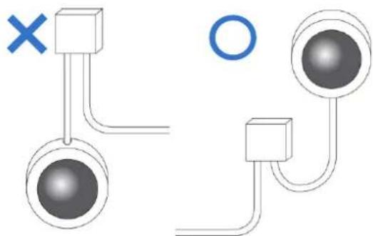
Note for Installing Camera Outdoor
When installing the camera outdoor, be sure that:
- The camera is set up above the junction box to prevent water from entering the camera along the cables.
natural_image
Diagram showing two connected components with a cross mark and a circle, no text or symbols present- Any PoE, power, audio and I/O cables are waterproofed using waterproof silicon rubber or the like.

natural_image
Diagram showing a mechanical component being twisted and then flattened, with no visible text or symbols.- The screws are tightened and the cover is in place after opening the camera cover.
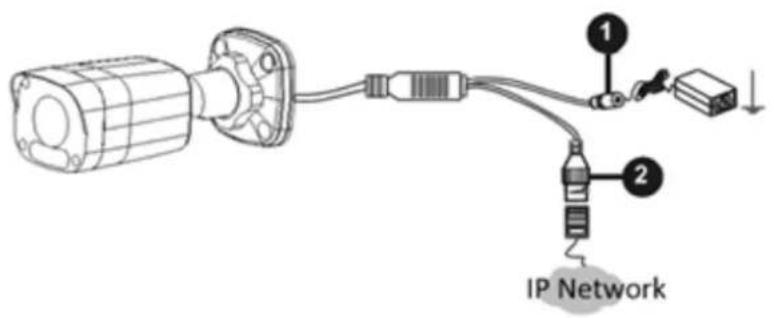
Note for Powering the Camera
The camera is powered by PoE or a power adapter. If you want to power the camera using the power connector, an optional power adapter is required.
Chapter 1 Introduction
1.1 GV-EBD Series and GV-EBFC5800
The H.265 Eyeball Dome is an outdoor, network camera equipped with an automatic IR-cut filter and IR LEDs for day and night surveillance. For GV-EBFC5800, it's equipped with full color smart warm LEDs for accurate day and night surveillance. The camera adheres to IP67 standards for dust / water protection and supports H.265 video codec to achieve better compression ratio while maintaining high quality image at reduced network bandwidths. With its WDR Pro (WDR for GV-EBD2702), it can process scenes with contrasting intensity of lights and produce clear image.
For GV-EBD4711 / 4712 / 4813 / 8711 / 8813, with their motorized lenses, the user can zoom and focus the camera from the Web interface. Certain camera models also provide built-in micro-SD card slot for local storage.
| Model No. | Specifications | Description | |
| GV-EBD2702 | Fixed lens | Fixed Iris, f: 2.8 mm, F/1.8, M12 Lens Mount | 2 MP, H.265, Low Lux, WDR |
| GV-EBD2704 | Fixed Iris, f: 2.8 mm, F/2.0, M12 Lens Mount | 2 MP, H.265, Low Lux, WDR Pro | |
| GV-EBD4700 | Fixed Iris, f: 2.8 mm, F/1.8, M12 Lens Mount | 4 MP, H.265, Super Low Lux, WDR Pro | |
| GV-EBD4701 | Fixed Iris, f: 2.8 mm, F/2.0, M12 Lens Mount | ||
| GV-EBD4704 | Fixed Iris, f: 2.8 mm, F/1.6, M12 Lens Mount | ||
| GV-EBD8700 | Fixed Iris, f: 2.8 mm, F/2.0, M12 Lens Mount | 8 MP, H.265, Low Lux, WDR Pro | |
| GV-EBD8800 | |||
| GV-EBD4711 | Motorized varifocal lens | Fixed Iris, f: 2.7 ~ 12 mm, F/1.4, ∅ 12 mm Lens Mount | 4 MP, H.265, Super Low Lux, WDR Pro |
| GV-EBD4712 | Fixed Iris, f: 2.8 ~ 12 mm, F/1.6, ∅ 12 mm Lens Mount | ||
| GV-EBD4813 | Fixed Iris, f: 2.7 ~ 13.5 mm, F/1.2, ∅ 12 mm Lens Mount | ||
| GV-EBD8711 | Fixed Iris, f: 2.8 ~ 12 mm F/1.5, ∅ 12 mm Lens Mount | 8 MP, H.265, Super Low Lux, WDR Pro | |
| GV-EBD8813 | Fixed Iris, f: 2.8 ~ 12 mm, F/1.6, ∅ 12 mm Lens Mount | ||
| GV-EBFC5800 | Fixed lens | Fixed Iris, f: 2.8 mm, F/1.0, M12 Lens Mount | 5 MP, H.265, Super Low Lux, WDR Pro, Warm LED |
1.1.1 Packing List
• H.265 Target Eyeball Dome
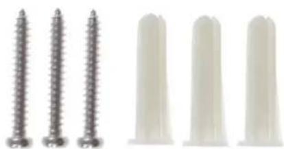
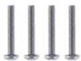
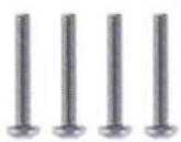
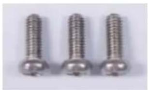
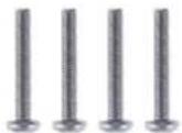
- Screw Kit
natural_image
Five dental screw and toothed dental implants shown in two different orientations (no text or labels visible)- Drill Template Paster
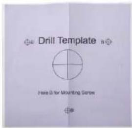
text_image
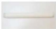
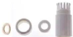
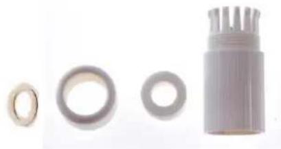
Drill Template Hole B for Mounting Screw- Waterproof Rubber Set
- Download Guide

natural_image
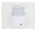
Product photo of four mechanical components: a ring, a washer, a cylindrical housing, and a textured cap (no text or symbols visible)1.1.2 Optional Accessories
Optional accessories can expand the capabilities and versatility of your camera. Contact your dealer for more information.
| Model Number | Name | Details |
| GV-Mount107(must be used with GV-Mount212P) | Pendant Bracket | Dimensions: 120 x 334 mm ( 4.72" x 13.15")Weight: 0.74 kg (1.63 lb) |
| GV-Mount211P | Wall Mount and Junction Box | Dimensions: 233 x 125 x 125 mm (9.2" x 4.9" x 4.9")Weight: 1 kg (2.2 lb) |
| GV-Mount212P | Wall Box Mount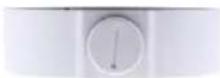 | Dimensions: 126 x 36 mm ( 5.0" x 1.4")Weight: 0.22 kg (0.48 lb) |
| GV-Mount300-2 | Convex Corner Mount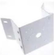 | Dimensions: 137 x 233 x 160 mm (5.4" x 9.17" x 6.3")Weight: 1.65 kg (3.64 lb) |
| GV-Mount310-2 | Concave Corner Mount | Dimensions: 111.2 x 369.9 x 210 mm (2.6" x 11.4" x 6.6")Weight: 1.65 kg (3.64 lb) |
| GV-Mount420(must be used with GV-Mount211P) | Pole Mount Bracket | Dimensions: ∅ 120 x 120 x 53.4 mm (∅ 4.7" x 4.7" x 2.1")Weight: 0.45 kg (0.99 lb)Steel Strap Diameter: ∅ 67 ~ 127 mm (∅ 2.6" ~ 5") |
| GV-Mount704(must be used with GV-Mount107) | Extension Tube | Dimensions: ∅ 3.5 x 10 or 20 or 30 or 50 cm (∅ 1.38 x 3.9 or 7.9 or 11.8 or 19.7")Weight: 225 g or 360 g or 500 g or 780 g (0.5 lb or 0.79 lb or 1.1 lb or 1.72 lb) |
| GV-PA191 | Power over Ethernet (PoE) Adapter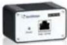 | GV-PA191 is a Power over Ethernet (PoE) adapter designed to provide power to the IP device through a single Ethernet cable. |
| GV-POE Switch | GV-POE Switch is designed to provide power along with network connection for IP devices. GV-POE Switch is available in various models with different numbers and types of ports. | |
| Power Adapter | Contact our sales representatives for the countries and areas supported. | |
1.1.3 Overview
1.1.3.1 GV-EBD2702 / 2704 / 4700 / 4701 / 4704 / 8700 / 8800 and GV-EBFC5800
text_image
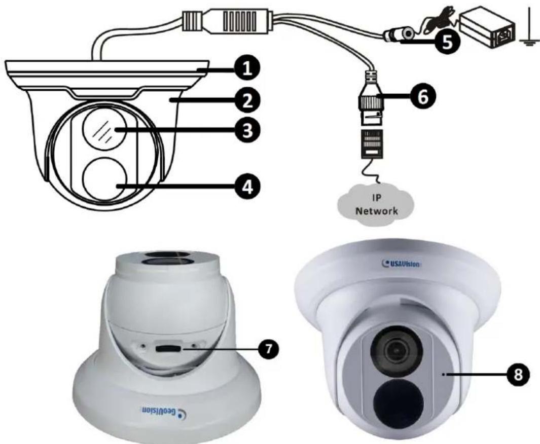
1 2 3 4 5 6 IP Network 7 8 GEVATION USAVisionFigure 1-1
| No. | Description |
| 1 | Bottom ring |
| 2 | Housing |
| 3 | Lens |
| 4 | Infrared indicator / Warm LEDs (GV-EBFC5800 only) |
| 5 | Power connector (DC 12 V) |
| 6 | Ethernet connector / PoE |
| 7 | Micro SD card slot (GV-EBD2704 / 4701 / 4704 / 8800 and GV-EBFC5800 only) |
| 8 | Microphone (GV-EBD2704 / 4701 / 4704 / 8800 and GV-EBFC5800 only) |
1.1.3.2 GV-EBD4711 / 4712 / 4813 / 8711 / 8813

text_image
① ② ③ ④ ⑤ ⑥ IP network ⑦ ⑧ ⑨Figure 1-2
| No. | Description |
| 1 | Bottom ring |
| 2 | Housing |
| 3 | Microphone |
| 4 | Lens |
| 5 | Power connector (DC 12 V) |
| 6 | Ethernet connector / PoE |
| 7 | Micro SD card slot and default button compartment |
| 8 | Default button |
| 9 | Micro SD card slot |
Note: If the default button doesn't respond after pressing for 15 seconds, reboot the camera and try again within 10 minutes of rebooting.
1.1.4 Installation
The Target Eyeball Dome is designed for outdoors. With the standard package, you can install the camera on the ceiling. Alternatively, you can purchase optional mounting accessories to mount the dome on a wall.
Below are the instructions for Ceiling Mount. There are two kinds of Ceiling Mount:
Concealed Installation and Open Installation. In concealed installation, the cables are hidden in the ceiling. In Open Installation, the cables are led out from the open slot on the bottom ring.
1.1.4.1 GV-EBD2702 / 2704 / 4700 / 4701 / 8700 / 8800 and GV-EBFC5800 Standard Installation
For Concealed Installation
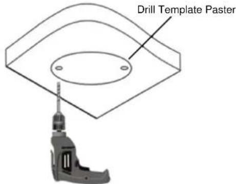
- Stick the drill template paster to the ceiling and drill three holes according to the drill template.

text_image
Drill Template PasterFigure 1-3
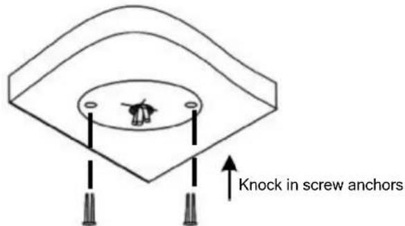
2. Insert the screw anchors.
Drill a hole to lead the cables out of the ceiling

text_image
Knock in screw anchorsFigure 1-4
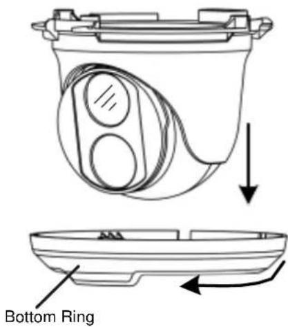
3. Remove the bottom ring by turning it anticlockwise.
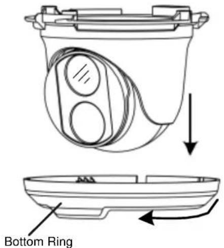
text_image
Bottom RingFigure 1-5
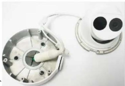
4. Connect the cables and secure the camera.

text_image
Connect the cables and protect them with waterproof tape Attach the camera to ceiling with screwsFigure 1-6
- Adjust the monitoring direction.

text_image
The camera can rotate 360 degrees horizontally The lens can rotate 80 degrees verticallyFigure 1-7
- Mount the bottom ring.

natural_image
Technical diagram of a mechanical component with directional arrows indicating motion (no text or symbols)Push the bottom ring back up and turn it clockwise to lock into position
Figure 1-8
For Open Installation
Lead the cables out from the open slot on the bottom ring before screwing the camera to the ceiling as shown in Figure 1-6.

text_image
Lock Open slot on the bottom ringFigure 1-9
1.1.4.2 GV-EBD4711 / 4712 / 4813 / 8711 / 8813 Standard Installation
For Concealed Installation
- Stick the drill template paster to the ceiling and drill three holes according to the drill template.
text_image
Drill Template PasterFigure 1-10
- Insert the screw anchors.
Drill a hole to lead the cables out of the ceiling
text_image
Knock in screw anchorsFigure 1-11
- Loosen the fixing screw and remove the housing by turning it to the position as shown.

text_image
Diagram illustrating a mechanical assembly process with labeled steps and component detailsFigure 1-12
- Secure the bottom ring to the ceiling with 3 supplied screws and connect the cable.

text_image
(Optional) insert a micro SD card Connect cable and protect it with waterproof tape Attach bottom ring to ceiling with taping screwsFigure 1-13
- Mount the housing by adjusting to the position as shown and press and turn to anywhere but ①.
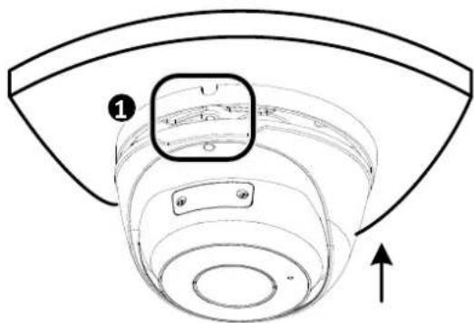
text_image
Technical diagram of a mechanical component with numbered annotation and directional arrowFigure 1-14
- Adjust the monitoring direction. Then tighten the screw.
natural_image
Technical line drawing of a mechanical component with a curved top and circular base, no text or symbols presentFigure 1-15
WARNING: Make sure the housing is not dismounted from the bottom ring when adjusting the monitoring direction. Unintentional removal of the housing may result in circumstantial damages.
For Open Installation
Lead the cables out from the open slot on the bottom ring before mounting the housing as shown in Figure 1-14.
natural_image
Technical line drawing of a mechanical component with concentric layers and mounting holes (no text or symbols)Open slot on the bottom ring
Figure 1-16
1.1.5 Optional Installation
You can optionally purchase the following accessories to fit your mounting environment:
• GV-Mount211P / GV-Mount212P for Wall Box Mount: see section 1.1.5.1 and 1.1.5.2.
• GV-Mount420 + GV-Mount211P for Pole Box Mount: see section 1.1.5.3.
• GV-Mount212P + GV-Mount107 for Pendant Tube Mount: see section 1.1.5.4.
• GV-Mount300-2 / 310-2 for Corner Mount: see Appendix F. GV-Mount300-2 / 310-2.
1.1.5.1 GV-Mount211P
text_image
GV-Mount211PFigure 1-17
GV-Mount211P Packing List
GV-Mount211P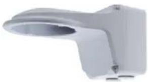 | Long Screw x 5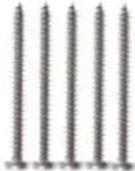 |
Short Screw x 4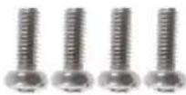 | Screw Anchor x 5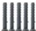 |
Plastic PG21 Conduit Connector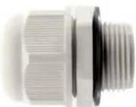 | Drill Template Paster |
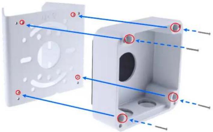
- Unscrew the bracket.
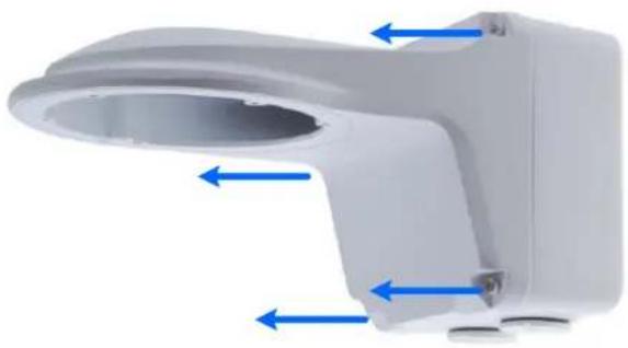
natural_image
3D rendering of a white plastic toilet or showerhead component with blue directional arrows indicating flow or movement (no text or symbols)Figure 1-18
- Loosen the indicated area by turning it anticlockwise.

text_image
Power BoxFigure 1-19
- Stick the drill template paster to the wall with the arrow pointing up.
- Drill 4 holes according to the sticker and insert the 4 screw anchors to the 4 holes.
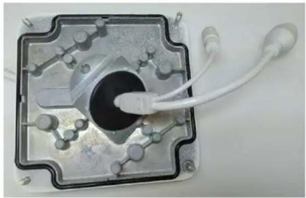
- Secure the power box to the wall with 4 long screws

natural_image
3D rendering of a white plastic enclosure with blue arrows indicating internal components (no text or symbols)Figure 1-20
- Remove the bottom ring by turning it anticlockwise.
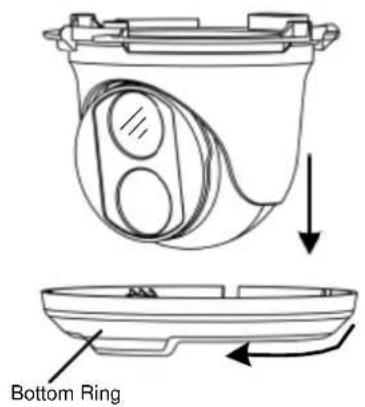
text_image
Bottom RingFigure 1-21
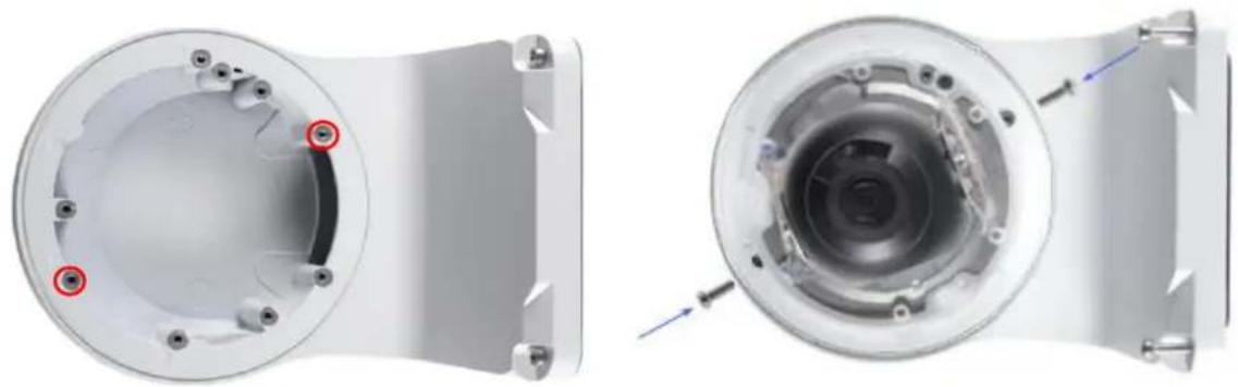
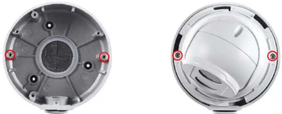
- Secure the camera to the wall mount bracket with the provided short screws according to the screw position for each model:
GV-EBD4700 / 4701 / 4704 / 4711 / 4712 / 4813 / 8700 / 8711 / 8800 / 8813 and GV-EBFC5800

natural_image
Technical illustration of a mechanical component with cross-sectional and top views, showing internal components and mounting holes (no text or symbols)Figure 1-22
GV-EBD2702 / 2704

natural_image
Technical illustration of a mechanical component with two views: top shows internal circular features, bottom shows a spherical housing with mounting holes and blue arrows indicating assembly or force (no text or symbols present)Figure 1-23
GV-ADR2701 / 4701

natural_image
Technical illustration of a mechanical component showing front and side views with red circular features (no text or symbols)Figure 1-24
GV-ADR2702 / ADR4702 / TDR2700 / TDR2702 / TDR2704 / TDR4700 / TDR4702 / TDR4703 / TDR4704 / TDR4803
natural_image
Two views of a mechanical component showing internal components and mounting holes (no text or symbols visible)Figure 1-25
- Thread the Ethernet cable through the PG21 conduit connector and the power box as shown in No. 8, Figure 1-26. Then connect the cable to the camera. To waterproof the cable, see 1.8 Waterproofing the Cable.
-
Rotate the plastic ring to secure the conduit connector to the power box. Screw in the cap as shown in No. 9, Figure 1-26.
-
Screw the wall mount bracket to the power box as shown in No. 10, Figure 1-26.
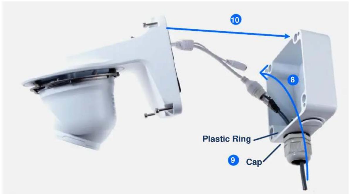
text_image
10 8 Plastic Ring 9 CapFigure 1-26
- Mount the bottom ring.
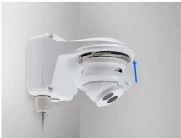
natural_image
Close-up of a white surveillance camera mounted on a wall, showing sensor array and a blue directional arrow (no text or symbols visible)Figure 1-27
1.1.5.2 GV-Mount212P
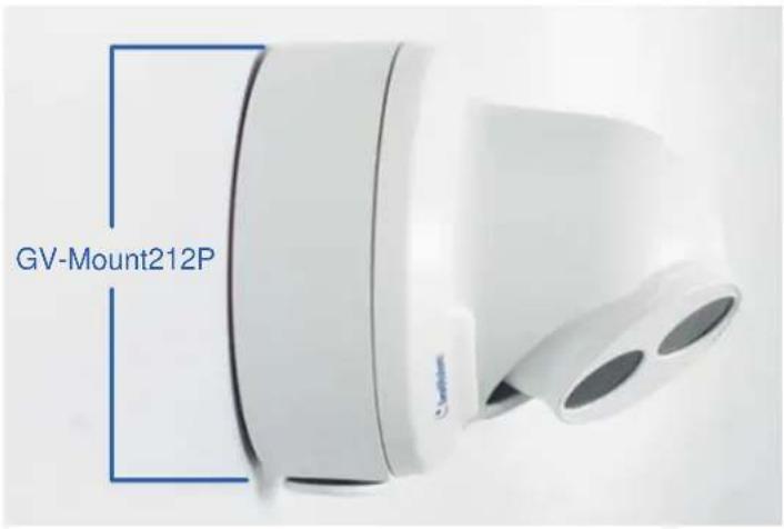
text_image
GV-Mount212PFigure 1-28
GV-Mount212P Packing List
GV-Mount212P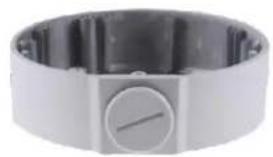 | Long Screw x 3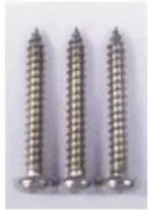 |
Short Screw x 3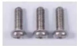 | Screw Anchor x 3 |
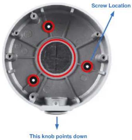
Standard Installation
1 Attach the wall box to the wall and use a marker to mark the location for the center socket and the screws. Make sure the knob points down.

text_image
Long Screw This knob points downFigure 1-29
2 Drill 3 holes according to the screw location. Then, drill a bigger hole at the center socket location for the Ethernet cable.
3 Insert 3 screw anchors to the screw location and secure the wall box to the wall with 3 long screws.
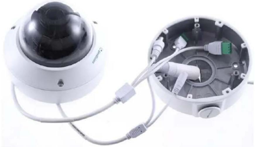
- Remove the bottom ring by turning it anticlockwise.
text_image
Bottom RingFigure 1-30
- Thread the Ethernet cable through the center socket and waterproof the Ethernet cable. For details, see 1.8 Waterproofing the Cable.
natural_image
Two white industrial sensor modules with circular components and a cylindrical sensor unit (no visible text or symbols)Figure 1-31
-
Fit the cable into the wall box.
-
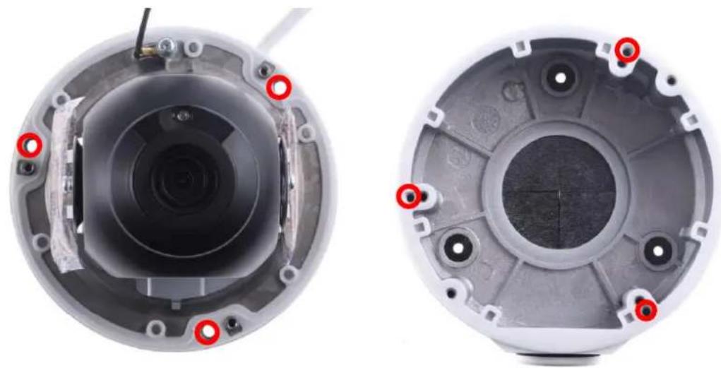
Secure the camera by locking the provided short screws to the screw position for each model:
GV-EBD2702 / 2704
natural_image
Two views of a white electronic device showing internal components and mounting holes (no text or symbols visible)Figure 1-32
GV-EBD4700 / 4701 / 4704 / 4711 / 4712 / 4813 / 8700 / 8711 / 8800 / 8813 and GV-EBFC5800
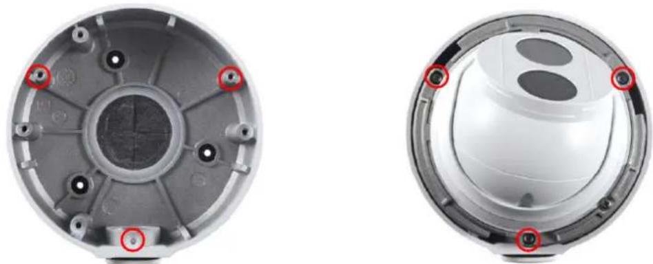
natural_image
Two views of a mechanical component showing internal structure with red circular markers (no text or symbols)Figure 1-33
8. Mount the bottom ring.
Note: In addition to the Standard Installation, you can also choose to run the Ethernet cable through a corrugated tube. To do this, you will have to purchase your own conduit connector and corrugated tube. 3/4" NPS is the recommended type of connector. After you secure the wall box to the desired location, remove the knob at the bottom and connect the conduit connector with a self-prepared corrugated tube to the wall box. Then, thread the Ethernet cable through the corrugated tube and waterproof the cable.
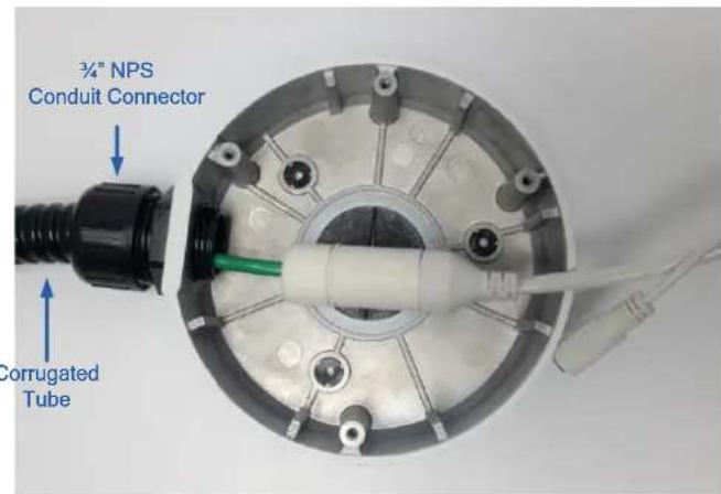
text_image
3/4" NPS Conduit Connector Corrugated TubeFigure 1-34
1.1.5.3 GV-Mount420 + GV-Mount211P
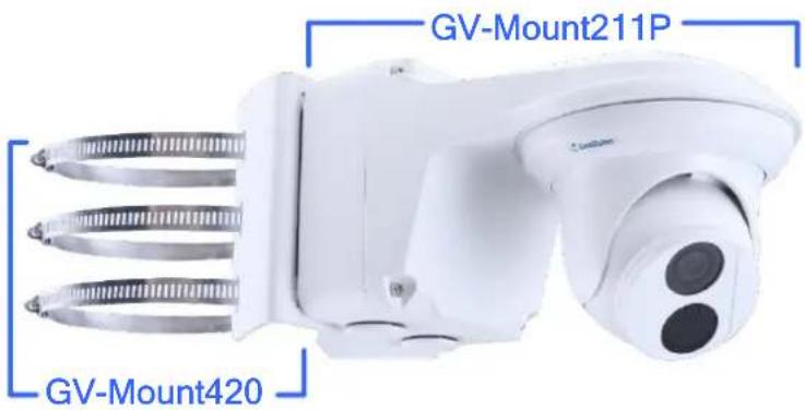
text_image
GV-Mount211P GV-Mount420Figure 1-35
GV-Mount420 Packing List
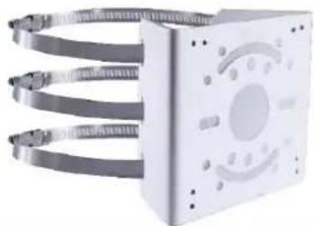
- GV-Mount420

natural_image
Exterior view of a white rectangular device with coiled metallic bands and a circular vent (no text or symbols visible)- M4 Screw x 4
• Additional Screw Kit
- M6 Screw x 4
- M6 Nut x 4
- M6 Plain Washer x 4
- M6 Split Washer x 4
Note: For GV-ADR / TDR / EBD Series, GV-Mount420 can only be used in conjunction with GV-Mount211P.
- Unscrew the bracket.
natural_image
3D rendering of a white plastic showerhead with blue directional arrows indicating flow or movement (no text or symbols)Figure 1-36
- Loosen the indicated area by turning it anticlockwise.

text_image
Power BoxFigure 1-37
- Align and attach the power box to the back plate using the 4 supplied M4 screws as indicated.

natural_image
3D diagram of a white plastic enclosure with mounting holes and internal cavity, showing blue arrows indicating direction (no text or symbols)Figure 1-38
Note: Make sure the direction of the "up ↑" indicator on the back plate match that of the power box.
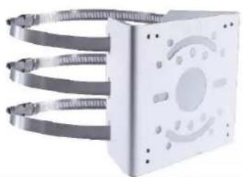
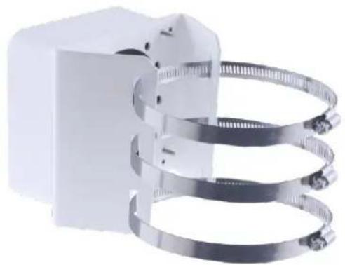
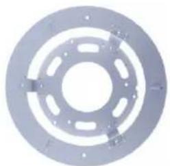
- Thread the 3 steel straps onto the back plate.

natural_image
White industrial clamp bracket with coiled metal chains (no text or symbols visible)Figure 1-39
- Follow Step 6 \~ 12 in 1.1.5.1 GV-Mount211P.
- Secure the camera onto the desired pole by tightening the steel straps.
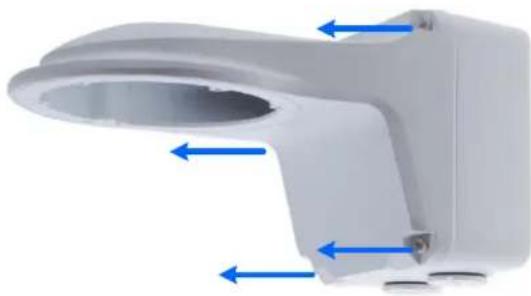
1.1.5.4 GV-Mount212P + GV-Mount107
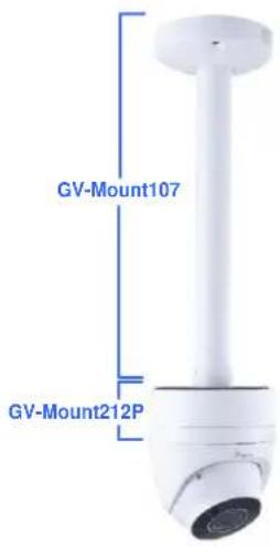
text_image
GV-Mount107 GV-Mount212PFigure 1-40
GV-Mount107 Packing List
- Pendant Bracket
- Pendant Tube
- Tube Connector
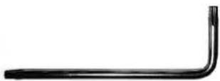
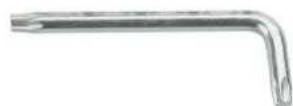
- Torx Wrench
Note: Before installing GV-Mount107, note the following.
• Install your GV-EBD Series camera on a GV-Mount212P by cutting a hole in the center of the mount and thread the camera wires through.
• Prepare 3 long screws for securing the Pendant Bracket to the ceiling.
• GV-Mount107 optionally extends with GV-Mount704.
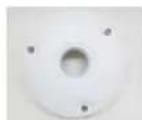
-
Place GV-Mount107 on the ceiling and mark the location for the center socket and the 3 screws.
-
Drill the marks and secure the Pendant Bracket onto the ceiling.
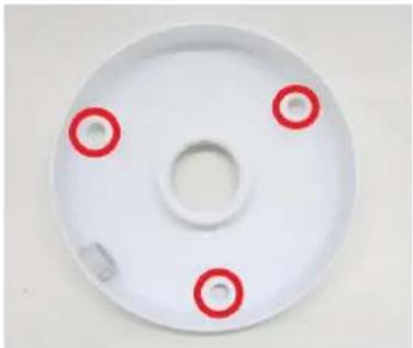
natural_image
White circular mechanical part with three red circular holes on its surface (no text or symbols)Figure 1-41
-
Attach one end of the Pendant Tube to the Pendant Bracket, and the other end to the Tube Connector.
-
Thread the necessary wires from the ceiling through the Pendant Tube and connect to the camera wires.
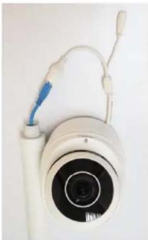
natural_image
Close-up of a white camera with a blue cable and attached cable, no visible text or symbols.Figure 1-42
-
Push and arrange the connected wires inside Mount212P.
-
Secure the camera onto the Tube Connector.
1.2 GV-ABL / TBL Series & GV-BLFC5800
The Bullet IP Camera is an outdoor, fixed, network camera equipped with an automatic IR-cut filter and an IR LED for day and night surveillance. For GV-BLFC5800, it's equipped with full color smart warm LEDs for accurate day and night surveillance. The camera supports H.265 video codec to achieve better compression ratio while maintaining high quality image at reduced network bandwidths. The camera adheres to IP66 / IP67 standards and can be powered through PoE.
| Model No. | Specifications | Description | |
| GV-ABL2701-0F | Fixed lens | Fixed Iris, f: 4.0 mm, F/1.8, M12 Lens Mount | 2 MP, H.265, Low Lux, WDR |
| GV-ABL2701-1F | Fixed Iris: f: 6.0 mm, F/1.8, M12 Lens Mount | ||
| GV-ABL2702 | Varifocal Lens | Fixed Iris, f: 2.8~12 mm, F/1.4, ∅ 14 mm Lens Mount | 2 MP, H.265, Low Lux, WDR Pro |
| GV-ABL2703-0F | Fixed lens | Fixed Iris, f: 4.0 mm, F/2.0, M12 Lens Mount | 2 MP, H.265, Low Lux, WDR |
| GV-ABL2703-1F | Fixed Iris: f: 6.0 mm, F/2.0, M12 Lens Mount | ||
| GV-ABL4701-0F | Fixed Iris, f: 4.0 mm, F/1.8, M12 Lens Mount | 4 MP, H.265, Super Low Lux, WDR | |
| GV-ABL4701-1F | Fixed Iris, f: 6.0 mm, F/1.8, M12 Lens Mount | ||
| GV-ABL4703 | Fixed Iris, f: 4.0 mm, F/2.0, M12 Lens Mount | ||
| GV-ABL4711 | Motorized varifocal lens | Fixed Iris, f: 2.8 ~ 12 mm, F/1.6, ∅ 14 mm Lens Mount | 4 MP, H.265, Super Low Lux, WDR Pro |
| GV-ABL4712 | Motorized varifocal lens | Fixed Iris, f: 2.8~12 mm, F/1.4, ∅ 14 mm Lens Mount | 4 MP, H.265, Super Low Lux, WDR Pro |
| GV-ABL8712 | 8 MP, H.265 Super Low Lux, WDR Pro | ||
| GV-TBL2703-0F | Fixed lens | Fixed Iris, f: 4.0 mm, F/2.0, M12 Lens Mount | 2 MP, H.265 Low Lux, WDR |
| GV-TBL2703-1F | Fixed Iris, f: 6.0 mm, F/2.0, M12 Lens Mount | 2 MP, H.265 Low Lux, WDR | |
| GV-TBL2705 | Fixed lens | Fixed Iris, f: 4.0 mm, F/2.0, M12 Lens Mount | 2 MP, H.265 Low Lux, WDR Pro |
| GV-TBL4700 | Varifocal lens | Fixed Iris, f: 2.8~12 mm, F/1.6, ∅ 14 mm Lens Mount | 4 MP, H.265, Super Low Lux, WDR |
| GV-TBL4703 | Fixed lens | Fixed Iris, f:4.0 mm, F/2.0, M12 Lens Mount | |
| GV-TBL4705 | Fixed lens | Fixed Iris, f:4.0 mm, F/1.6, M12 Lens Mount | 4 MP, H.265, Super Low Lux, WDR Pro |
| GV-TBL4710 | Motorized varifocal lens | Fixed Iris, f: 2.8 ~ 12 mm, F/1.4, ∅ 14 mm Lens Mount | |
| GV-TBL4711 | Fixed Iris, f: 2.8 ~ 12 mm,F/1.6, ∅ 14 mm Lens Mount | 4 MP, H.265, SuperLow Lux, WDR Pro | |
| GV-TBL4810 | Fixed Iris, f: 2.7 ~ 13.5 mm,F/1.2, ∅ 14 mm Lens Mount | ||
| GV-TBL8710 | Fixed Iris, f: 2.8 ~ 12 mm,F/1.5, ∅ 14 mm Lens Mount | 8 MP, H.265, SuperLow Lux, WDR Pro | |
| GV-TBL8804 | Fixed lens | Fixed Iris, f:4.0 mm, F/2.0,M12 Lens Mount | 8 MP, H.265, SuperLow Lux, WDR Pro,Warm LED |
| GV-TBL8810 | Motorizedvarifocal lens | Fixed Iris, f: 2.8 ~ 12 mm,F/1.6, ∅ 14 mm Lens Mount | 8 MP, H.265, SuperLow Lux, WDR Pro |
| GV-BLFC5800 | Fixed lens | Fixed Iris, f: 4 mm, F/1.0, M12Lens Mount | 5 MP, H.265, SuperLow Lux, WDR Pro,Warm LED |
1.2.1 Packing List
- Bullet IP Camera
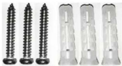
- Screw Kit
-
Download Guide
-
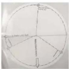
Drill Template Paster
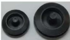
- Waterproof Rubber Set
natural_image
Close-up of four metallic mechanical components: a washer, a ring, a bushing pin, and a cylindrical housing (no text or symbols visible)1.2.2 Optional Accessories
Optional accessories can expand the capabilities and versatility of your camera. Contact your dealer for more information.
| Model Number | Name | Details |
| GV-Mount300-2 | Convex Corner Mount | Dimensions: 137 x 233 x 160 mm (5.4" x 9.17" x 6.3")Weight: 1.65 kg (3.64 lb) |
| GV-Mount310-2 | Concave Corner Mount | Dimensions: 111.2 x 369.9 x 210 mm (2.6" x 11.4" x 6.6")Weight: 1.65 kg (3.64 lb) |
| GV-Mount420 (must be used with GV-Mount503) | Pole Mount Bracket | Dimensions: 0 120 x 120 x 53.4 mm (0 4.7" x 4.7" x 2.1")Weight: 0.45 kg (0.99 lb)Steel Strap Diameter: 0 67 ~ 127 mm (0 2.6" ~ 5") |
| GV-Mount502 (for GV-ABL2701 Series / 2703 Series / 4701 Series / 4703 & TBL2703 Series / 4703) | Wall Mount Bracket | Dimensions: 93 x 93 x 39 mm (3.66" x 3.66" x 1.53")Weight: 0.235 kg (0.52 lb) |
| GV-Mount503 (for GV-ABL2702 / 4711 / 4712 / 8712, GV-TBL4700 / 4710 / 4711 / 8710 / 8810, GV-BLFC5800) | Wall Mount Bracket | Dimension: 125 x 125 x 55 mm (4.9" x4.9" x2.2")Weight: 0.74 kg (1.63lb) |
| GV-Mount504 (for GV-TBL2705 / 4705 / 8804) | Wall Mount Bracket | Dimensions: 0 104.4 x 54.5 mm (0 4.11" x 2.15")Weight: 0.36 kg (0.79 lb) |
| GV-PA191 | Power over Ethernet (PoE) Adapter | GV-PA191 is a Power over Ethernet (PoE) adapter designed to provide power to the IP device through a single Ethernet cable. |
| GV-POE Switch | GV-POE Switch is designed to provide power along with network connection for IP devices. GV-POE Switch is available in various models with different numbers and types of ports. | |
| Power Adapter | Contact our sales representatives for the countries and areas supported. | |
Note: All GV-Mount accessories mentioned above are not applicable to GV-TBL2705 / 4705 / 8804, except GV-Mount504.
1.2.3 Overview
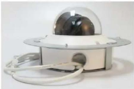
1.2.3.1 GV-ABL2701 / 2703 / 4701 / 4703 & TBL2703 / 2705 / 4703 / 4705 / 8804
text_image
IP NetworkFigure 1-43
| No. | Description | No. | Description |
| 1 | Power connector (DC 12 V) | 2 | Ethernet connector / PoE |
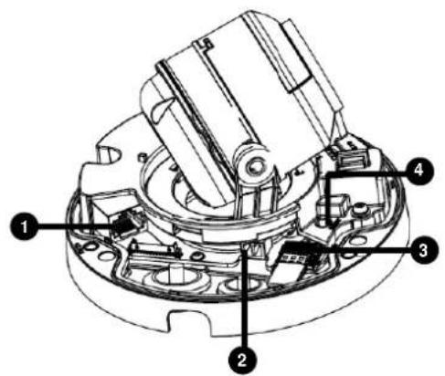
Load Default Button (for GV-ABL2703 / 4703 & TBL2703 / 4703 / 8804 only)
text_image
39mm (1.54") Φ4.5mm (0.18)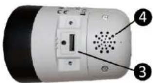
text_image
Labeled diagram of a device showing ports, speaker, and speaker grille with numbered annotations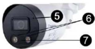
text_image
Labeled diagram of a cylindrical device with numbered parts, showing front, top, and side views.
natural_image
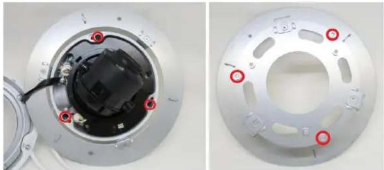
Close-up of a mechanical component with numbered annotations (8 and 9) pointing to features, no readable text or symbols beyond labels.Figure 1-44
| No. | Description | No. | Description |
| 1 | Load default button | 6 | Warm LED Light x 2 (GV-TBL8804) |
| 2 | Grounding screw (GV-TBL8804) | 7 | IR Light x 1 (GV-TBL8804) |
| 3 | Load default button / SD card slot (GV-TBL8804)SD card slot (GV-TBL2705 / 4705 / 8804) | 8 | Built-in microphone (GV-TBL2705 / 4705) |
| 4 | Built-in speaker (GV-TBL8804) | 9 | IR Light x 2 (GV-TBL2705 / 4705) |
| 5 | Built-in microphone (GV-TBL8804) |
Note:
- For safety precautions, it is recommended to connect a grounding wire to the grounding screw, and do not loosen or remove the grounding screw under any circumstances.
- If the default button doesn't respond after pressing for 15 seconds, reboot the camera and try again within 10 minutes of rebooting.
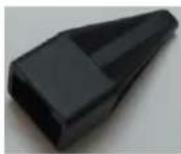
1.2.3.2 GV-ABL2702 / 4711 / 4712 / 8712, TBL4700 / 4710 / 4711 / 4810 / 8710 / 8810, and BLFC5800

text_image
Diagram of a device with labeled components including a flashlight, connectors, and a power outletFigure 1-45
| No. | Description |
| 1 | Power connector (DC 12 V) |
| 2 | Audio input / Audio output / GND |
| 3 | Alarm input (IN, GND) / Alarm output (N, P) |
| 4 | Ethernet connector / PoE |
| 5 | Video Output (GV-ABL8712 / TBL8710 Only) |
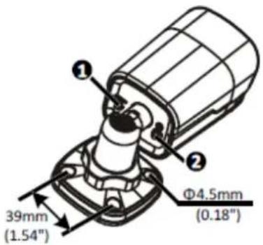
1.2.4 Installation
The Bullet IP Camera is designed for outdoors. With the standard package, you can install the camera on the wall or ceiling. Or, you can purchase optional mounting accessories to mount your camera on a wall.
Below are the instructions for Wall Mount. There are two kinds of Wall Mount: Concealed Installation and Open Installation. In Concealed Installation, the cables are hidden in the wall. In Open Installation, the cables are led out from the open slot on the base.
For Concealed Installation
- For GV-ABL2702 / 4711 / 4712 / 8712, TBL2705 / 4700 / 4705 / 4710 / 4711 / 4810 / 8710 / 8804 / 8810, and BLFC5800, optionally loosen the two screws at the bottom of the camera to insert a SD card.

text_image
A B Micro SD slotFigure 1-46
-
Stick the drill template paster to the wall and align the cross center to the hole in the wall.
-
Lead the cables across the hole on the wall.

natural_image
Diagram of a mechanical component with cross-shaped cutout and curved end, shown in 3D perspective (no text or symbols)GV-ABL2702 / 4711 / 4712 / 8712 TBL4700 / 4710 / 4711 / 4810 / 8710 / 8810 BLFC5800
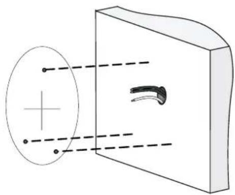
natural_image
Diagram showing a crosshair passing through an eye lens and projecting a curved object into a rectangular chamber (no text or symbols)GV-TBL2705 / 4705 / 8804
Figure 1-47
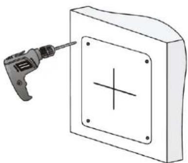
- Drill the holes according to the drill template.
natural_image
Illustration of a screwdriver inserted into a rectangular panel with a cross symbol (no text or labels)GV-ABL2702 / 4711 / 4712 / 8712 TBL4700 / 4710 / 4711 / 4810 / 8710 / 8810 BLFC5800

natural_image
Illustration of a power tool next to a square electronic component with a circular crosshair (no text or symbols)GV-TBL2705 / 4705 / 8804
Figure 1-48
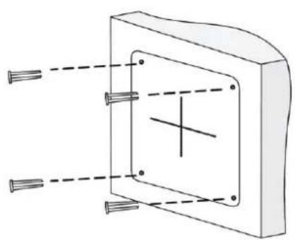
- Insert the screw anchors.
natural_image
Pure technical diagram of a mechanical component with no text, numbers, or symbolsGV-ABL2702 / 4711 / 4712 / 8712 TBL4700 / 4710 / 4711 / 4810 / 8710 / 8810 BLFC5800
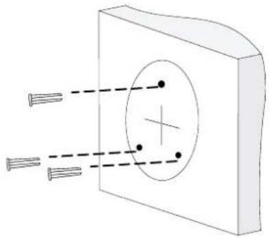
natural_image
Diagram of a rectangular block with internal circular structure and two parallel screw holes, no text or symbols presentGV-TBL2705 / 4705 / 8804
Figure 1-49
- Screw the locknut and loosen the universal joint before attaching the camera to the wall.
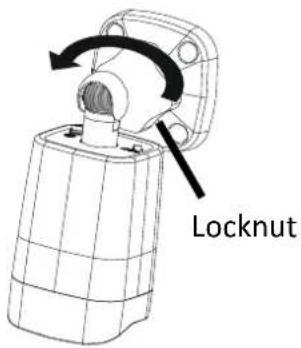
text_image
LocknutFigure 1-50
- Secure the camera to the wall and connect all cables.
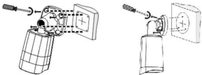
natural_image
Technical line drawing of a hand tool and a spray bottle assembly (no text or symbols)Lead tapping screws through the guide holes in the base and fix them on the wall by using a screwdriver.
Figure 1-51
- To adjust the monitoring direction:
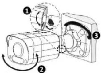
GV-ABL2702 / 4711 / 4712 / 8712, TBL4700 / 4705 / 4710 / 4711 / 4810 / 8710 / 8804 / 8810, and BLFC5800
text_image
Technical diagram of a mechanical assembly with numbered components and directional arrows indicating motion or force① Adjust the opening of the universal joints as required.
2 Rotate the spherical hinge of the camera to get the desired monitoring direction.
③ Tighten the locknut.
Figure 1-52-1
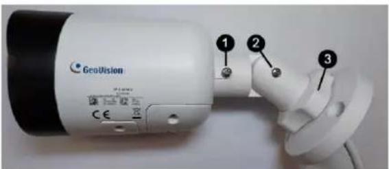
GV-TBL2705 / 4705 / 8804
text_image
GeoVision 1 2 3① Loosen the screw to rotate the camera.
2 Loosen the screw to move the camera upward or downward.
③ Loosen the locknut to rotate the camera.
Figure 1-52-2
For Open Installation
Lead the cables out from the open slot on the base before screwing the camera to the wall as shown in Figure 1-51.
1.2.5 Optional Installation
For GV-ABL2701 Series / 2703 Series / 4701 Series / 4703 & TBL2703 Series / 4703, you can optionally purchase the following accessories to fit your mounting environment:
• GV-Mount502 for Wall Box Mount: see section 1.2.5.1.
For GV-ABL2702 / 4711 / 4712 / 8712, TBL4700 / 4710 / 4711 / 4810 / 8710 / 8810, and BLFC5800, you can optionally purchase:
• GV-Mount503 for Wall Box Mount: see section 1.2.5.2.
• GV-Mount420 + GV-Mount503 for Pole Box Mount: see section 1.2.5.3.
• GV-Mount300-2 / 310-2 for Corner Mount: see Appendix F. GV-Mount300-2 / 310-2.
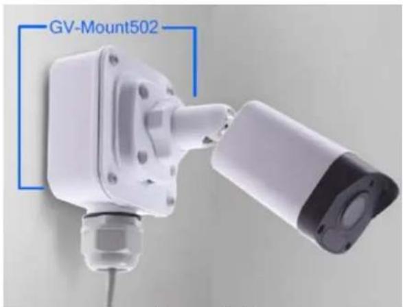
text_image
GV-Mount502Figure 1-53
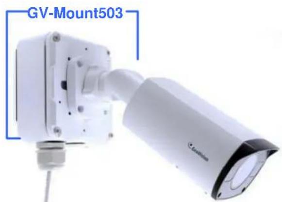
text_image
GV-Mount503Figure 1-54

text_image
GV-Mount503 GV-Mount420Figure 1-55
For GV-TBL2705 / 4705 / 8804, you can optionally purchase:
• GV-Mount504 for Wall Mount: see section 1.2.5.4.
1.2.5.1 GV-Mount502
GV-Mount502 Packing List
GV-Mount502 | M3 25 mm Screw x 4 |
M3 12 mm Screw x 4 | Screw Anchor x 4 |
Plastic PG21 Conduit Connector |
- Unscrew the box cover.

natural_image
White mechanical component with blue directional arrows indicating force or movement (no text or symbols)Figure 1-56
- Loosen the knob by turning it anticlockwise.
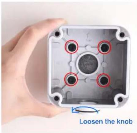
text_image
Loosen the knobFigure 1-57
- Attach the box to the wall with the knob pointing down and use a marker to mark 4 dots.
- Drill 4 holes according to the marks.
- Insert the 4 screw anchors to the holes and secure the box to the wall with 4 long screws.
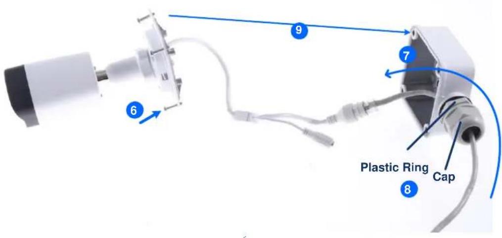
- Secure the camera to the box cover with 4 short screws, as illustrated in No. 6, Figure 1-58.
- Thread the Ethernet cable through the PG21 conduit connector and the wall box, as shown in No. 7, Figure 1-58. Then connect the cable to the camera. To waterproof the Ethernet cable, see 1.8 Waterproofing the Cable.
- Rotate the plastic ring to secure the conduit connector to the wall box. Screw in the cap, as shown in No. 8, Figure 1-58.
- Screw the box cover to the wall box, as shown in No. 9, Figure 1-58.
text_image
Plastic Ring CapFigure 1-58
1.2.5.2 GV-Mount503
GV-Mount503 Packing List
GV-Mount503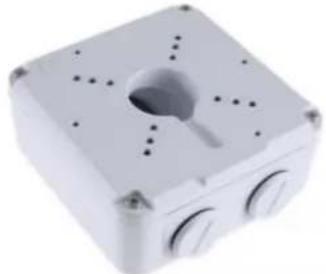 | Long Screw x 4 |
Short Screw x 4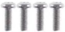 | Screw Anchor x 4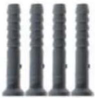 |
Plastic PG21 Conduit Connector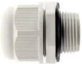 | Waterproof Rubber Plug |
- Unscrew the box cover.

natural_image
Pure diagram of a device with central lens and surrounding dots, no text or symbols presentFigure 1-59
- Loosen the knobs by turning it anticlockwise.

text_image
Long Screw Loosen the knobFigure 1-60
- Attach the box to the wall with the knobs pointing down and use a marker to mark 4 dots.
- Drill 4 holes according to the marks.
- Insert 4 screw anchors to the holes and secure the to the wall with 4 long screws.
- Thread the camera cable through the box cover and secure the camera to the cover with 4 short screws.
- Reattach the box cover to the power box, as shown in No. 7, Figure 1-61.
- Thread the Ethernet cable through the PG21 conduit connector and the power box as shown in No 8, Figure 1-61. Then connect the cable to the camera. To waterproof the cable, see 1.8 Waterproofing the Cable.
- Rotate the plastic ring to secure the conduit connector to the power box. Secure in the cap, as shown in No 9, Figure 1-61
- Secure the box cover to the power box, as shown in No 10, Figure 1-61.

text_image
Gas Chromatometer 7 10 Plastic Ring 8 9 CapFigure 1-61
Note: Alternatively, you can use the supplied waterproof rubber plug to seal the box cover by following the steps below.
- Thread the camera cable through the box cover, and then through the supplied waterproof rubber plug from the bottom side.
natural_image
Close-up of a mechanical component with attached wires and connectors (no visible text or symbols)Figure 1-62
- Align the gap of the waterproof rubber plug to the direction of the "up ↑" indicator and press firmly to embed the waterproof plug onto the inside of the box cover.
- Thread the Ethernet cable through the power box and connect to the camera. Secure the box cover to the power box.
1.2.5.3 GV-Mount420 + GV-Mount503
GV-Mount420 Packing List
- GV-Mount420
natural_image
Exterior view of a white industrial enclosure with coiled metal strips and a circular vent (no text or symbols visible)- M4 Screw x 4
• Additional Screw Kit
- M6 Screw x 4
- M6 Nut x 4
- M6 Plain Washer x 4
- M6 Split Washer x 4
Note: For GV-ABL2702 / 4711 / 4712 / 8712 and GV-TBL4700 / 4710 / 4711 / 4810 / 8710 / 8810, GV-Mount420 can only be used in conjunction with GV-Mount503.
- Follow Step 1 & 2 in 1.2.5.2 GV-Mount503.
- Align and attach the power box to the back plate using the 4 supplied M4 screws as indicated.
natural_image
3D diagram of a white plastic housing with blue directional arrows indicating force or movement, no text or symbols present.Figure 1-63
Note: Make sure the direction of the "up ↑" indicator on the back plate matches that of the power box.
- Thread the 3 steel straps onto the back plate.
natural_image
White industrial clamp bracket with three metal coiled tubing (no text or symbols visible)Figure 1-64
- Follow Step 6 \~ 10 in 1.2.5.2 GV-Mount503.
- Secure the camera onto the desired pole by tightening the steel straps.
1.2.5.4 GV-Mount504
GV-Mount504 Packing List
| GV-Mount504 | Long Screw x 4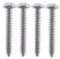 |
Short Screw x 3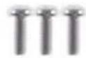 | Screw Anchor x 4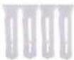 |
Drill Template Paster | Waterproof Rubber Plug |
Plastic PG21 Conduit Connector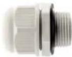 |
- Unscrew the box cover.

natural_image
3D rendering of a mechanical component with red directional arrows indicating force or flow (no text or symbols)Figure 1-65
- Stick the drill template paster to the wall with the arrow pointing up.
- Drill the 4 mounting holes according to the drill template.
-
Insert the 4 screw anchors to the mounting holes.
-
Position the power box on the wall with the "up " indicator pointing up and align the screw holes indicated below to the 4 mounting holes on the wall.

natural_image
Close-up of a mechanical component with multiple ports and a central hub (no visible text or symbols)Figure 1-66
-
Secure the power box to the wall with the supplied long screws.
-
Thread the Ethernet cable through the center hole (proceed to Step 9) or through the PG21 conduit connector and the power box as shown in No 8, Figure 1-61 (proceed to Step 8).
-
Rotate the plastic ring to secure the conduit connector to the power box. Secure in the cap, as shown in No 9, Figure 1-61.
-
Thread the camera cable through the box cover from the top, and then attach the supplied waterproof rubber plug to the camera cable at around the camera base, as shown in the figure below.

natural_image
Mechanical component with cylindrical housing and mounting bracket (no visible text or symbols)Figure 1-67
-
Press firmly to embed the waterproof plug onto the box cover.
-
Use the supplied short screws to secure the camera to the box cover at the indicated holes below.

natural_image
Close-up of a mechanical component with red circular markers indicating features (no text or symbols visible)Figure 1-68
- Connect the Ethernet cable to the camera cable, align the "up ↑" indicators on the box cover and power box, and then secure the box cover to the power box.
1.3 GV-ADR / TDR Series
The IR Mini Fixed Rugged IP Dome is an outdoor, fixed, network camera equipped with an automatic IR-cut filter and an IR LED for day and night surveillance. The camera supports H.265 video codec to achieve better compression ratio while maintaining high quality image at reduced network bandwidths. The WDR Pro models can produce clear image for scenes containing contrasting intensity of lights.
| Model No. | Specifications | Description | |
| GV-ADR2701 | Fixed lens | Fixed Iris, f: 2.8 mm,F/2.2, M12 Lens Mount | 2 MP, H.265,Low Lux, WDR |
| GV-ADR2702-0F | Fixed Iris, f: 2.8 mm,F/2.0, M12 Lens Mount | 2 MP, H.265, Low Lux, WDR | |
| GV-ADR2702-1F | Fixed Iris, f: 4 mm,F/2.0, M12 Lens Mount | ||
| GV-ADR4701 | Fixed Iris, f: 2.8 mm,F/1.8, M12 Lens Mount | 4 MP, H.265, Super Low Lux, WDR | |
| GV-ADR4702-0F | Fixed Iris, f: 2.8 mm,F/2.0, M12 Lens Mount | ||
| GV-ADR4702-1F | Fixed Iris, f: 4 mm,F/2.0, M12 Lens Mount | ||
| GV-TDR2700-0F | Fixed Iris, f: 2.8 mm,F/1.6, M12 Lens Mount | 2 MP, H.265, Low Lux, WDR Pro | |
| GV-TDR2700-1F | Fixed Iris, f: 4 mm,F/1.6, M12 Lens Mount | ||
| GV-TDR2702-0F | Fixed Iris, f: 2.8 mm,F/2.0, M12 Lens Mount | 2 MP, H.265, Low Lux, WDR | |
| GV-TDR2702-1F | Fixed lens | Fixed Iris, f: 4 mm,F/2.0, M12 Lens Mount | 2 MP, H.265, Low Lux, WDR |
| GV-TDR2704-2F | Fixed Iris, f: 2.8 mm,F/2.0, M12 Lens Mount | 2 MP, H.265, Low Lux, WDR Pro | |
| GV-TDR2704-4F | Fixed Iris, f: 4 mm,F/2.0, M12 Lens Mount | ||
| GV-TDR4700-0F | Fixed Iris, f: 2.8 mm,F/2.0, M12 Lens Mount | 4 MP, H.265, Super Low Lux, WDR Pro | |
| GV-TDR4700-1F | Fixed Iris, f: 3.6 mm,F/2.0, M12 Lens Mount | ||
| GV-TDR4702-0F | Fixed Iris, f: 2.8 mm,F/2.0, M12 Lens Mount | 4 MP, H.265, Super Low Lux, WDR | |
| GV-TDR4702-1F | Fixed Iris, f: 4 mm,F/2.0, M12 Lens Mount | ||
| GV-TDR4703-2F | Fixed Iris, f: 2.8 mm,F/2.0, M12 Lens Mount | 4 MP, H.265, Super Low Lux, WDR Pro | |
| GV-TDR4703-4F | Fixed Iris, f: 4 mm,F/2.0, M12 Lens Mount | ||
| GV-TDR4704-2F | Fixed Iris, f: 2.8 mm,F/1.6, M12 Lens Mount | ||
| GV-TDR4704-4F | Fixed Iris, f: 4 mm,F/1.6, M12 Lens Mount | ||
| GV-TDR4803-2F | Fixed lens | Fixed Iris, f: 2.8 mm, F/1.6, M12 Lens Mount | 4 MP, H.265, Super Low Lux, WDR Pro |
| GV-TDR4803-4F | Fixed Iris, f: 4 mm, F/1.6, M12 Lens Mount | ||
| GV-TDR8805 | Fixed lens | Fixed Iris, f: 2.8 mm, F/1.6, M12 Lens Mount | 5 MP, H.265, Super Low Lux, WDR Pro |
1.3.1 Packing List
• IR Mini Fixed Rugged IP Dome

natural_image
Front view of a white GeoRichest surveillance camera (no visible text or symbols on body)- Waterproof Rubber Set

natural_image
Four metallic mechanical components: a circular ring, two circular washers, and a cylindrical housing (no text or symbols visible)- Screw Kit

natural_image
Five different types of screw fasteners shown from different angles (no text or symbols visible)- Drill Template Paster
- Download Guide
- Torx wrench (comes with some models)
1.3.2 Optional Accessories
Optional accessories can expand the capabilities and versatility of your camera. Contact your dealer for more information.
| Model Number | Name | Details |
| GV-Mount107(must be used with GV-Mount213) | Pendant Bracket | Dimensions: 0 120 x 334 mm (0 4.72" x 13.15")Weight: 0.74 kg (1.63 lb) |
| GV-Mount211P | Wall Mount and Junction Box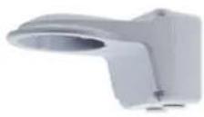 | Dimensions: 233 x 125 x 125 mm (9.2" x 4.9" x 4.9")Weight: 1 kg (2.2 lb) |
| GV-Mount213 | Wall / Ceiling Box Mount | Dimensions: 0 109 x 39 mm(0 4.3" x 1.5")Weight: 0.2 kg (0.44 lb) |
| GV-Mount300-2(must be used with GV-Mount211P or GV-Mount213 for GV-ADR2701/4701) | Convex Corner Mount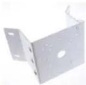 | Dimensions: 137 x 233 x 160 mm (5.4" x 9.17" x 6.3")Weight: 1.65 kg (3.64 lb) |
| GV-Mount310-2(must be used with GV-Mount211P or GV-Mount213 for GV-ADR2701/4701) | Concave Corner Mount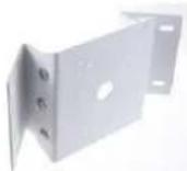 | Dimensions: 111.2 x 369.9 x 210 mm (2.6" x 11.4" x 6.6")Weight: 1.65 kg (3.64 lb) |
| GV-Mount420(must be used with GV-Mount211P) | Pole Mount Bracket | Dimensions: 0 120 x 120 x 53.4 mm(0 4.7" x 4.7" x 2.1")Weight: 0.45 kg (0.99 lb)Steel Strap Diameter: 0 67 ~ 127 mm (0 2.6" ~ 5") |
| GV-Mount704(must be used with GV-Mount107) | Extension Tube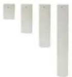 | Dimensions: 0 3.5 x 10 or 20 or 30 or 50 cm (0 1.38 x 3.9 or 7.9 or 11.8 or 19.7")Weight: 225g or 360g or 500g or 780g (0.5 lb or 0.79 lb or 1.1 lb or 1.72 lb) |
| GV-PA191 | Power over Ethernet (PoE) Adapter  | GV-PA191 is a Power over Ethernet (PoE) adapter designed to provide power to the IP device through a single Ethernet cable. |
| GV-POE Switch | GV-POE Switch is designed to provide power along with network connection for IP devices. GV-POE Switch is available in various models with different numbers and types of ports. | |
| Power Adapter | Contact our sales representatives for the countries and areas supported. | |
1.3.3 Overview
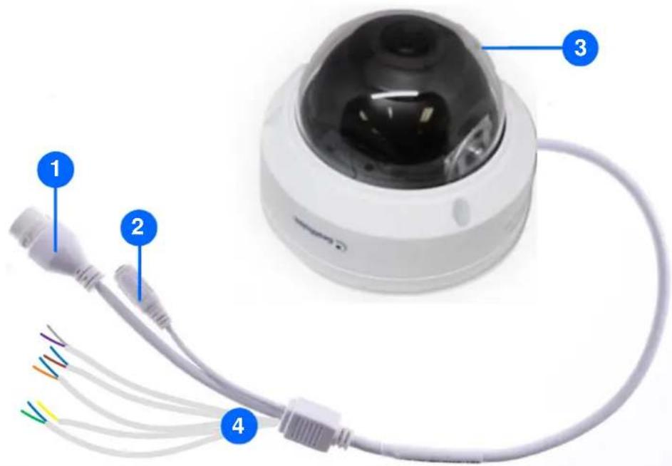
text_image
Labeled diagram of a surveillance camera with four colored wires connected to its base, showing component 1, 2, 3, and 4.Figure 1-69
| No. | Description |
| 1 | Ethernet connector / PoE |
| 2 | Power connector (DC 12 V) |
| 3 | Transparent Dome Cover |
| 4 | For GV-TDR2700 / 4700 / 4703 / 4803 series and GV-TDR8805 only, see the table below. |
Wire Definition
| GV-TDR2700 series / 4700 series | GV-TDR4703 series / 4803 series / GV-TDR8805 | ||
| Wire | Definition | Wire | Definition |
| Green | Audio in | Gray | Audio Out |
| Blue | GND | Purple | GND |
| Yellow | Alarm Out | Green | Audio In |
| White | Alarm Out | Brown | GND |
| Orange | Alarm Input | Orange | Alarm Input |
| Blue | GND | Blue | GND |
| Brown | Audio in | Yellow | Alarm Output |
| Blue | GND | White | Alarm Output |
| Gray | Audio Out | ||
| Purple | GND | ||
1.3.4 Installation
The IR Mini Fixed Rugged IP Dome is designed for outdoors. With the standard package, you can install the camera on the ceiling.
Below are the instructions for Ceiling Mount. There are two kinds of Ceiling Mount:
Concealed Installation and Open Installation. In Concealed Installation, the cables are hidden in the ceiling. In Open Installation, the cables are led out from the open slot on the camera base.
For Concealed Installation
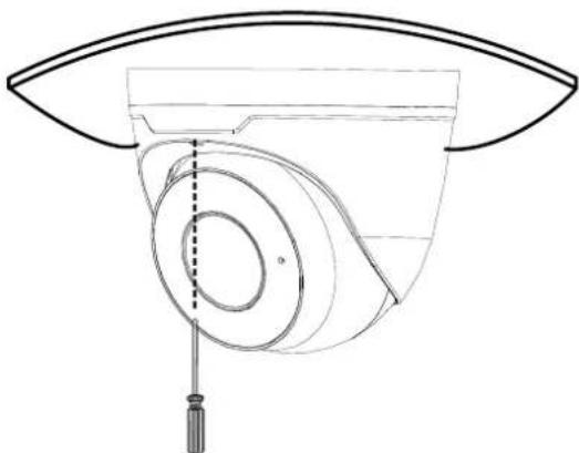
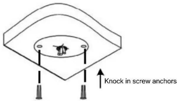
- Stick the drill template paster to the ceiling and drill 30-mm deep holes according to the drill template.
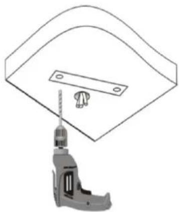
natural_image
Technical line drawing of a mechanical component with a drill bit and screw hole (no text or symbols)Figure 1-70
- Insert the screw anchors.
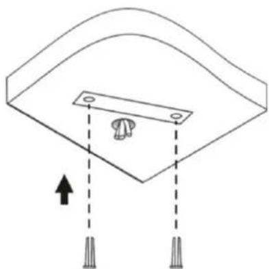
natural_image
Diagram of a mechanical component with arrows indicating direction, no text or symbols presentFigure 1-71
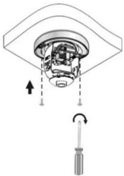
- Unscrew the transparent dome cover with the supplied torx wrench.
- Connect the cables and secure the camera.

natural_image
Diagram of a mechanical component with arrows indicating motion, showing internal structure and screwdriver (no text or symbols)Figure 1-72
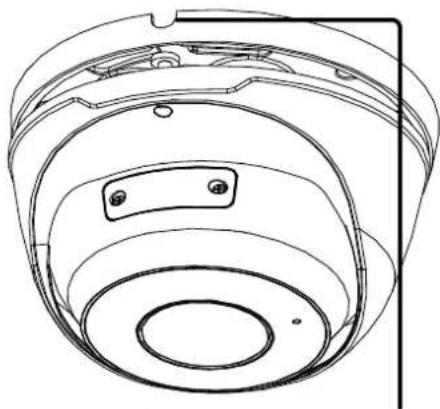
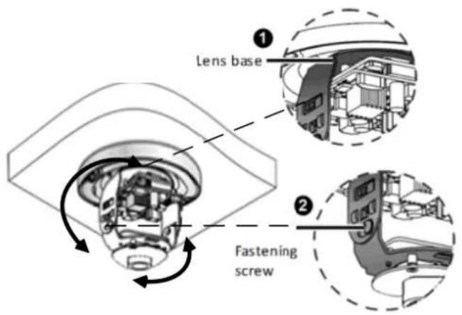
- Adjust the monitoring direction and tighten the screws after vertically adjusting the lens.
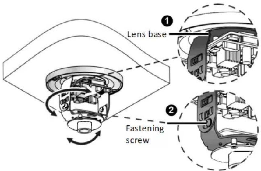
text_image
Lens base Fastening screwFigure 1-73
- Secure the transparent dome cover with the supplied torx wrench.

natural_image
Mechanical assembly diagram showing a component with a screwdriver and curved arrow indicating rotation (no text or symbols)Figure 1-74
Note: Before securing the transparent dome cover, make sure the waterproof rubber strip is tightly held by the six retainers on the bottom ring.

natural_image
Close-up of a camera lens assembly with blue circular annotations pointing to key components (no text or symbols visible)Figure 1-75
For Open Installation
Lead the cables out from the open slot on the camera base before screwing the camera to the ceiling as shown in Figure 1-72.
1.3.5 Optional Installation
You can optionally purchase the following accessories to fit your mounting environment:
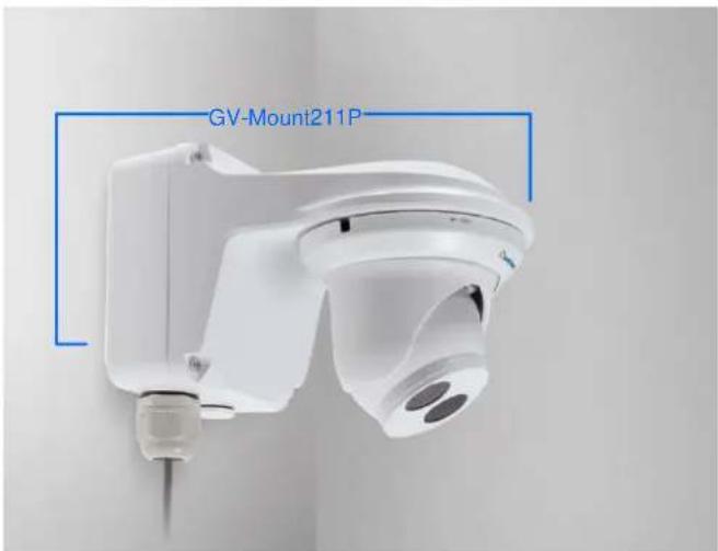
• GV-Mount211P for Wall Mount: see section 1.1.5.1.
• GV-Mount213 for Wall / Ceiling Box Mount: see section 1.3.5.1
• GV-Mount420 + GV-Mount211P for Pole Box Mount: see section 1.1.5.3.
• GV-Mount213 + Mount107 for Pendant Bracket Mount: see section 1.1.5.4.
• GV-Mount300-2 / 310-2 for Corner Mount: see Appendix F. GV-Mount300-2 / 310-2.
1.3.5.1 GV-Mount213
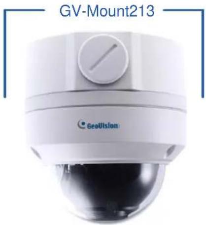
text_image
GV-Mount213 GeoUtlsonFigure 1-76
GV-Mount213 Packing List
GV-Mount213 | Long Screw x 3 |
Short Screw x 3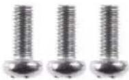 | Screw Anchor x 3 |
- Attach the GV-Mount213 to the wall / ceiling and use a marker to mark the location for the center socket and the 3 screws.

natural_image
Close-up of a mechanical component with red circular features and mounting holes (no text or symbols visible)Figure 1-77
Note: To prevent rain from getting into GV-ADR2701 / 2702 / 4701 / 4702 & TDR2702 / 2704 / 4702 / 4703 / 4704 / 4803 / 8805,
- For ceiling mount installation, turn the indicated hole inwards.
- For wall mount installation, make sure the indicated hole points down and towards the ground.

text_image
Sensipase 37-01-04/2021 Sensipase 37-01-04/2021 Sensipase 37-01-04/2021 Sensipase 37-01-04/2021 Sensipase 37-01-04/2021 Sensipase 37-01-04/2021 Sensipase Sensipase Sensipase Sensipase Sensipase Sensipase Sensipase Sensipase Sensipase Sensipase Sensipase Sensipase Sensipase Sensipase Sensipase Sensipase Sensipase Sensipase Sensipase Sensipase Sensipuse Sensipuse Sensipuse Sensipuse Sensipuse Sensipuse Sensipuse Sensipuse Sensipuse Sensipuse Sensipuse Sensipuse Sensipuse Sensipuse Sensipuse Sensipuse Sensipuse Sensipuse Sensipuse Sensipuse Sensipuses Sensipuses Sensipuses Sensipuses Sensipuses Sensipuses Sensipuses Sensipuses Sensipuses Sensipuses Sensipuses Sensipuses Sensipuses Sensipuses Sensipuses Sensipuses Sensipuses Sensipuses Sensipuses Sensipuses Sensipus Sensipuses Sensipuses Sensipuses Sensipuses Sensipuses Sensipuses Sensipuses Sensipuses Sensipuses Sensipuses Sensipuses Sensipuses Sensipuses Sensipuses Sensipuses Sensipuses Sensipuses Sensipsuses Sensipsuses Sensipsuses Sensipsuses Sensipsuses Sensipsuses Sensipsuses Sensipsuses Sensipsuses Sensipsuses Sensipsuses Sensipsuses Sensipsuses Sensipsuses Sensipsuses Sensipsuses Sensipsuses Sensipsuses Sensipsuses SensipsusesFigure 1-78
-
Drill 3 holes according to the screw locations. Then, drill a bigger hole at the center socket location for the Ethernet cable.
-
Insert 3 screw anchors to the screw locations and secure the GV-Mount213 to the wall / ceiling with 3 long screws.
-
Thread the Ethernet cable through the center socket and waterproof the Ethernet cable. For details, see 1.8 Waterproofing the Cable.
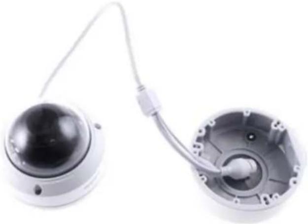
natural_image
Two views of a smart security camera module with exposed wiring and central hub (no text or symbols visible)Figure 1-79
-
Fit the cable into the GV-Mount213.
-
Remove the camera cover and fasten the camera to the wall box mount as indicated below using the supplied short screws.
GV-ADR2701 / 4701
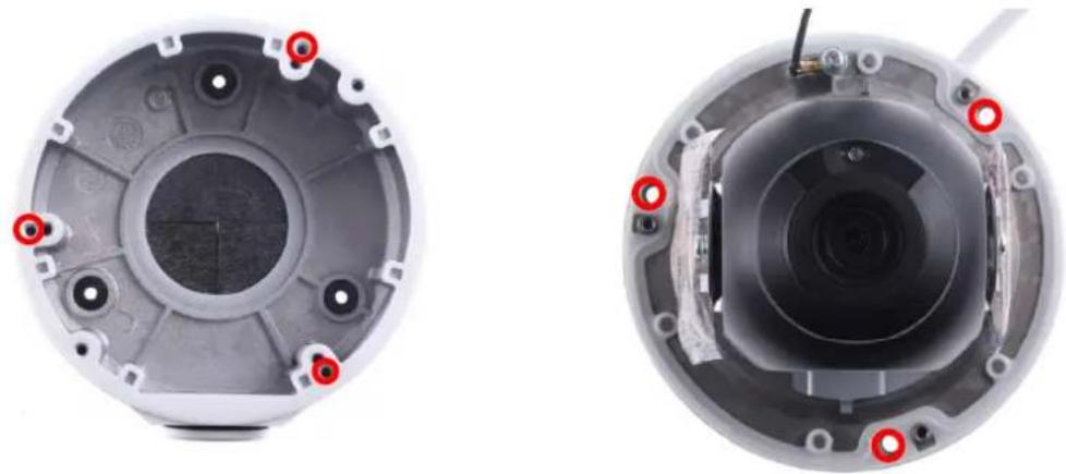
natural_image
Two views of a mechanical device showing internal components with red circular markers (no text or symbols visible)Figure 1-80
GV-ADR2702 / ADR4702 / TDR2700 / TDR2702 / TDR2704 / TDR4700 / TDR4702 / TDR4703 / TDR4704 / TDR4803 / TDR8805

natural_image
Top-down view of a mechanical component with mounting holes and central bore (no text or symbols visible)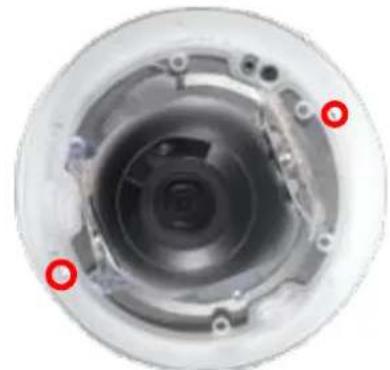
natural_image
Close-up of a mechanical component with red circular markers indicating features (no text or symbols visible)Figure 1-81
- Secure the camera cover.
Note: In addition to the Standard Installation, you can also choose to run the Ethernet cable through a corrugated tube. To do this, see Figure 1-34 and its related Note.
1.4 GV-AVD / TVD Series
The Vandal Proof IP Dome is an outdoor camera designed with IK10 vandal resistance and IP67 ingress protection. The camera is equipped with an automatic IR-cut filter and IR LEDs for day and night surveillance. Adjustable in 3 axes (pan, tilt and rotate), it offers an entry-level surveillance solution with all the essential features and excellent image quality.
| Model No. | Specifications | Description | |
| GV-AVD2700 | Varifocal lens | Fixed Iris, f: 2.8~12 mm, F/1.4, ∅ 14 mm Lens Mount | 2MP, H.265, Low Lux, WDR |
| GV-AVD4710 | Motorized varifocal lens | 4 MP, H.265, Super Low Lux, WDR Pro | |
| GV-AVD8710 | Fixed Iris, f: 2.8~12 mm, F/1.5, ∅ 14 mm Lens Mount | 8 MP, H.265, Super Low Lux, WDR Pro | |
| GV-TVD4700 | Varifocal lens | Fixed Iris, f: 2.8~12 mm, F1.6, ∅ 14 mm Lens Mount | 4 MP, H.265, Super Low Lux, WDR |
| GV-TVD4710 | Motorized varifocal lens | Fixed Iris, f: 2.8~12 mm, F/1.4, ∅ 14 mm Lens Mount | 4 MP, H.265, Super Low Lux, WDR Pro |
| GV-TVD4711 | Fixed Iris, f: 2.8~12 mm, F/1.6, ∅ 14 mm Lens Mount | 4 MP, H.265, Super Low Lux, WDR Pro | |
| GV-TVD4810 | Fixed Iris, f: 2.7~13.5 mm, F/1.2, ∅ 14 mm Lens Mount | 4 MP, H.265, Super Low Lux, WDR Pro | |
| GV-TVD8710 | Fixed Iris, f: 2.8~12 mm, F/1.5, ∅ 14 mm Lens Mount | 8 MP, H.265, Super Low Lux, WDR Pro | |
| GV-TVD8810 | Fixed Iris, f: 2.8~12 mm, F/1.6, ∅ 14 mm Lens Mount | ||
| Note: GV-Mount606 is not supported by GV-TVD4711. | |||
1.4.1 Packing List
1.4.1.1 GV-TVD4711
- IR Vandal Proof IP Dome
- Drill Template Paster
text_image
Circle with radius 100 Right side Left side Right side- Spare Waterproof Rubber Plug
natural_image
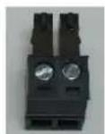
Two black plastic buttons with circular centers, no text or symbols visible• 2-Pin Power Terminal Block

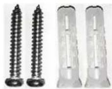
- Screw Kit
natural_image
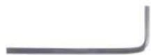
Five different types of screw fasteners shown from different angles (no text or symbols visible)- Torx Wrench

natural_image
Metal L-shaped tool or bracket with a pointed tip and tapered end (no text or symbols visible)• Cable Protection Connector
- Download Guide
1.4.1.2 GV-AVD / TVD Series
• IR Vandal Proof IP Dome
- Waterproof Rubber Set
natural_image
Four metallic mechanical components: a ring, a washer, a cylindrical housing, and a separate cylindrical component (no text or symbols visible)- Screw Kit

natural_image
Five different types of screw fasteners shown from different angles (no text or symbols visible)- Drill Template Paster
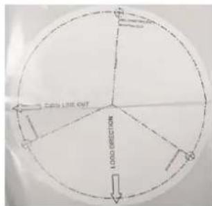
text_image
Empty LINE OUT LOAD DIRECTION- Torx Wrench

natural_image
Metal L-shaped tool or bracket with a sharp tip and flared end (no text or symbols visible)- Download Guide
1.4.2 Optional Accessories
Optional accessories can expand the capabilities and versatility of your camera. Contact your dealer for more information.
| Model Number | Name | Details |
| GV-Mount107(must be used with GV-Mount212P / GV-Mount212-2) | Pendant Bracket | Dimensions: 0 120 x 334 mm(∅ 4.72" x 13.15")Weight: 0.74 kg (1.63 lb) |
| GV-Mount211-2 | Wall Mount and Junction Box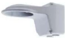 | Dimensions: 253 x 125 x 125 mm(10" x 4.9" x 4.9")Weight: 0.92 kg (2.02 lb) |
| GV-Mount211P(for GV-TVD4711) | Dimensions: ∅ 233 125 x 125 mm(∅ 9.2 x 4.9 x 4.9")Weight: 1 kg (2.2 lb) | |
| GV-Mount212-2 | Ceiling Box Mount | Dimensions: ∅ 145 x 40 mm(∅ 5.7" x 1.6")Weight: 0.24 kg (0.5 lb) |
| GV-Mount212P(for GV-TVD4711) | Dimensions: ∅ 126 x 36 mm(∅ 5.0 x 1.4")Weight: 0.22 kg (0.48 lb) | |
| GV-Mount300-2 | Convex Corner Mount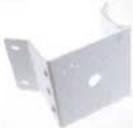 | Dimensions: 137 x 233 x 160 mm(5.4" x 9.17" x 6.3")Weight: 1.65 kg (3.64 lb) |
| GV-Mount310-2 | Concave Corner Mount | Dimensions: 111.2 x 369.9 x 210mm (2.6" x 11.4" x 6.6")Weight: 1.65 kg (3.64 lb) |
| GV-Mount420(must be used with GV-Mount211P / GV-Mount211-2) | Pole Mount Bracket | Dimensions: ∅ 120 x 120 x 53.4mm (∅ 4.7" x 4.7" x 2.1")Weight: 0.45 kg (0.99 lb)Steel Strap Diameter: ∅ 67 ~ 127mm (∅ 2.6" ~ 5") |
| GV-Mount606 | In-Ceiling Mount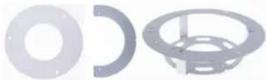 | Dimensions: ∅ 235 x 63 mm (∅9.3" x 2.5")In-ceiling hole: ∅ 195 mm (∅ 7.67")Weight: 0.49 kg (1.1 lb) |
| GV-Mount704(must be used with GV-Mount107) | Extension Tube | Dimensions: ∅ 3.5 x 10 or 20 or 30 or 50 cm (∅ 1.38 x 3.9 or 7.9 or 11.8 or 19.7")Weight: 225g or 360g or 500g or 780g (0.5 lb or 0.79 lb or 1.1 lb or 1.72 lb) |
| GV-Mount921(for standard US single and double gang boxes only) | Power over Ethernet (PoE) Adapter | Dimensions: ∅ 145 x 13 mm (∅ 5.7" x 0.5")Weight: 0.13 kg (0.29 lb) |
| GV-PA191 | Power over Ethernet (PoE) Adapter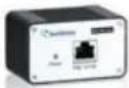 | GV-PA191 is a Power over Ethernet (PoE) adapter designed to provide power to the IP device through a single Ethernet cable. |
| GV-POE Switch | GV-POE Switch is designed to provide power along with network connection for IP devices. GV-POE Switch is available in various models with different numbers and types of ports. | |
| Power Adapter | Contact our sales representatives for the countries and areas supported. | |
Note: GV-Mount606 / Mount921 is not applicable to GV-TVD4711.
1.4.3 Overview
1.4.3.1 GV-AVD2700 / 4710 / 8710, GV-TVD4700 / 4710 / 4810 / 8710 / 8810

text_image
Technical diagram of a security camera module with labeled components including sensor, connector, and display panelFigure 1-82
| No. | Description | No. | Description |
| 1 | Power connector (DC 12 V) | 6 | Default button |
| 2 | Ethernet connector / PoE | 7 | Micro SD card slot |
| 3 | Video output(Not applicable to GV-TVD4700 / 8810) | 8 | Default button (For GV-TVD8810) |
| 4 | Audio input / Audio output / GND (Not applicable to GV-TVD4700) | 9 | Micro SD card slot (For GV-TVD8810) |
| 5 | Alarm input (IN, GND) / Alarm output(N, P) (Not applicable to GV-TVD4700) | 10 | Built-in microphone (For GV-TVD8810) |
Note: If the default button doesn't respond after pressing for 15 seconds, reboot the camera and try again within 10 minutes of rebooting.
1.4.3.2 GV-TVD4711
text_image
Technical diagram of a mechanical assembly with numbered components for identification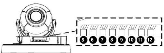
text_image
Technical diagram of a mechanical device with numbered components and a zoomed-in detail view showing internal structure.Figure 1-83
| No. | Description | No. | Description |
| 1 | Ethernet port | 7 | GND |
| 2 | Power port (2-Pin terminal block) | 8 | Digital Input |
| 3 | Micro SD card slot | 9 | GND |
| 4 | Default button | 10 | Audio In |
| 5 | Digital Output (N) | 11 | GND |
| 6 | Digital Output (P) | 12 | Audio Out |
Note: There are two ways to supply power to the camera:
- Use a Power over Ethernet (PoE) adapter to connect the camera to the network, and the power will be provided at the same time.
- Plug the power adapter to the supplied 2-pin terminal block by inserting the striped wire to the right pin (-) and the black wire to the left pin (+), then insert the 2-pin terminal block to Power Connector, No. 2.

natural_image
Simple electrical circuit diagram showing a green terminal block connected to a black plug via a wire, with no text or symbols present.Figure 1-84
1.4.4 Installation
The Target Vandal Proof Dome is designed for outdoors. With the standard package, you can install the camera on the ceiling. Alternatively, you can purchase optional mounting accessories to mount the camera on a wall.
Below are the instructions for Ceiling Mount. There are two kinds of Ceiling Mount:
Concealed Installation and Open Installation. In Concealed Installation, the cables are hidden in the ceiling. In Open Installation, the cables are led out from the open slot on the camera base.
1.4.4.1 GV-AVD2700 / 4710 / 8710, GV-TVD4700 / 4710 / 4810 / 8710 /
8810
For Concealed Installation
- Stick the drill template paster to the ceiling, and then drill three holes according to the drill template.

text_image
Drill Template PasterFigure 1-85
- Insert the screw anchors.
Drill a hole to lead the cables out of the ceiling
text_image
Knock in screw anchorsFigure 1-86
-
Unscrew the transparent dome cover with the supplied torx wrench.
-
Connect the camera cables and secure the camera.
natural_image
Diagram of a mechanical component with an arrow indicating upward and downward motion, showing internal structure and a screwdriver (no text or symbols)Figure 1-87
- Insert a SD card into the slot.
- Adjust the monitoring direction and tighten the screws after vertically adjusting the lens.
text_image
Lens base Fastening screwFigure 1-88
- Secure the transparent dome cover with the supplied torx wrench.
For Open Installation
Lead the cables out from the open slot on the camera base before screwing the camera to the ceiling as shown in Figure 1-87.
1.4.4.2 GV-TVD4711
- Follow steps 1 to 3 in 1.4.4.1 GV-AVD2700 / 4710 / 8710, GV-TVD4700 / 4710 / 4810 / 8710 / 8810.
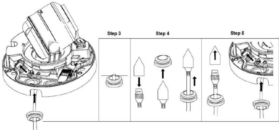
To install an Ethernet / PoE cable:
- Remove the large waterproof rubber plug from the base of the camera.
- Cut a small opening on the tip of the large waterproof rubber plug.
- Attach the cable protection connector to the Ethernet cable head and push the Ethernet cable through the opening.
- Remove the cable protection connector. Thread the Ethernet cable through the large hole to connect to the camera and press to embed the waterproof rubber plug.
text_image
Step 3 Step 4 Step 5Figure 1-89
To install optional power and I/O wires:
- Repeat steps 2 to 3 for the small waterproof rubber plug at the base of the camera.
- Push the power and I/O wires through the opening on the small waterproof plug.
- Thread the wires through the small hole and press to embed the waterproof rubber plug.
-
Attach the supplied 2-pin terminal block to the power wires.
-
Connect the 2-pin terminal block and I/O wires to the camera.
Tip: When connecting the I/O wires to the camera, thread the I/O wires through the protruded loop.
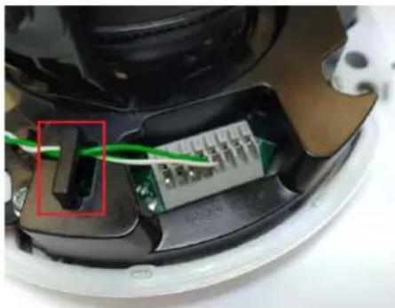
natural_image
Close-up of an electronic device showing a green cable inserted into a black housing, with a numbered component highlighted (no visible text or symbols)Figure 1-90
To finish the installation:
- Secure the camera and insert a micro SD card to the slot.
- Secure the transparent dome cover with the supplied torx wrench.
1.4.5 Optional Installation
You can optionally purchase the following accessories to fit your mounting environment:
• GV-Mount211P / GV-Mount212P for Wall Box Mount: see section 1.1.5.1 and 1.1.5.2.
• GV-Mount420 + GV-Mount211P for Pole Box Mount: see section 1.1.5.3.
- GV-Mount212P / GV-Mount212-2 + GV-Mount107 for Pendant Tube Mount: see section 1.1.5.4.
• GV-Mount211-2 for Wall Mount: see section 1.4.5.1.
• GV-Mount212-2 for Wall / Ceiling Box Mount: see section 1.4.5.2.
• GV-Mount420 + GV-Mount211-2 for Pole Box Mount: see section 1.4.5.3.
• GV-Mount606 for In-Ceiling Bracket Mount: see section 1.4.5.4.
• GV-Mount300-2 / 310-2 for Corner Mount: see Appendix F. GV-Mount300-2 / 310-2.
1.4.5.1 GV-Mount211-2
natural_image
Exterior view of a white surveillance camera with a spherical lens and mounted sensor (no visible text or symbols)Figure 1-91
GV-Mount211-2 Packing List
GV-Mount211-2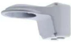 | Long Screw x 5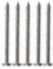 |
Short Screw x 4 | Screw Anchor x 5 |
Plastic PG21 Conduit Connector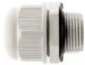 | Drill Template Paster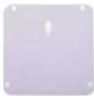 |
-
To install the power box from the wall mount bracket on the wall, follow steps 1 to 5 in 1.1.5.1 GV-Mount211P.
-
Unscrew the transparent dome cover with the supplied torx wrench.

natural_image
Top-down view of a spherical security camera with blue arrows pointing to the lens (no text or symbols visible)Figure 1-92
- Optionally insert a SD card into the slot.
- Thread the camera cables through the bracket.
- Secure the camera to the wall mount bracket with the provided short screws.

natural_image
Top-down view of a white plastic mechanical component with red pins and mounting holes (no text or symbols visible)
natural_image
Top-down view of a mechanical component with central bore and mounting holes (no visible text or symbols)Figure 1-93
- Thread the Ethernet cable through the PG21 conduit connector and the power box, as shown in No 6, Figure 1-90. Then connect the cable to the camera.
- Rotate the plastic ring to secure the conduit connector to the power box. Screw in the cap shown in No 7, Figure 1-90.
- Screw the wall mount bracket to the power box, as shown in No. 8, Figure 1-94.

text_image
8 Plastic Ring 6 7 CapFigure 1-94
1.4.5.2 GV-Mount212-2
GV-Mount212-2

natural_image
Close-up of a GeoVision security camera with a dome lens and control knob (no visible text or symbols on the device body)Figure 1-95
GV-Mount212-2 Packing List
- GV-Mount212-2

natural_image
Circular metallic object with a central knob, no visible text or symbols- Long Screw x 3

natural_image
Three metallic screw fasteners arranged horizontally (no text or symbols visible)- Short Screw x 3
natural_image
Three metallic screw fasteners arranged horizontally (no text or symbols visible)- Screw Anchor x 3

natural_image
Three vertical cylindrical objects with horizontal lines, no visible text or symbols- Attach the ceiling box to the ceiling and use a marker to mark the location for the center socket and the screws. Make sure the knob points inwards.
text_image
Screw Location This knob points downFigure 1-96
-
Drill 3 holes according to the screw location. Then, drill a bigger hole at the center socket location for the Ethernet cable.
-
Insert 3 screw anchors to the screw location and secure the ceiling box to the ceiling with 3 long screws.
-
Thread the Ethernet cable through the center socket, connect other wires and fit the camera cable into the ceiling box. See 1.8 Waterproofing the Cable.
natural_image
Exterior view of a surveillance camera module with exposed wiring and internal components (no text or symbols visible)Figure 1-97
-
Unscrew the transparent dome cover with the supplied torx wrench.
-
Secure the camera to the ceiling box.
natural_image
Two views of a mechanical device showing internal components with red circular markers (no text or symbols visible)Figure 1-98
Note: In addition to the Standard Installation, you can also choose to run the Ethernet cable through a corrugated tube. To do this, see Figure 1-34 and its related Note.
1.4.5.3 GV-Mount420 + GV-Mount211-2

text_image
GV-Mount211-2 GV-Mount420Figure 1-99
GV-Mount420 Packing List
- GV-Mount420
natural_image
Exterior view of a white industrial cooling unit with coiled metal pipes (no text or symbols visible)- M4 Screw x 4
• Additional Screw Kit
- M6 Screw x 4
- M6 Nut x 4
- M6 Plain Washer x 4
- M6 Split Washer x 4
Note: For GV-AVD Series, GV-Mount420 can only be used in conjunction with GV-Mount211-2.
- Follow Step 1 \~ 4 in 1.1.5.3 GV-Mount420 + GV-Mount211P.
- Follow Step 2 \~ 8 in 1.4.5.1 GV-Mount211-2.
- Secure the camera onto the desired pole by tightening the steel straps.
1.4.5.4 GV-Mount606

text_image
GV- Mount606Figure 1-100
GV-Mount606 Packing List
• In-Ceiling Mount Bracket
natural_image
Circular mechanical component with concentric rings and mounting holes (no text or symbols)- In-Ceiling Cover

natural_image
Circular white object with a central hole and four small holes, resembling a ring or washer (no text or symbols)- In-Ceiling Plate
- Drill Template Paster

text_image
Hole for Inceiling Mount Mounting Drill Diameter(0.195mm)- Screw Kit:
- M4 Screw (8 mm) x 3
-
M4 Screw (40 mm) x 2
-
Paste the drill template to the ceiling and drill the ceiling to the size of the drill template.
- Place the In-Ceiling Plate behind the ceiling with the flat side facing down.
- Loosen the knob on the side of the camera and thread the camera wires through.
- Thread the camera wires through the side of the In-Ceiling Mount Bracket and place the camera in the Mount Bracket.
natural_image
Exterior view of a white satellite or spacecraft with a dome-shaped head and attached cables (no text or symbols visible)Figure 1-101
- Open the transparent dome cover and insert the 3 M4 Screws (8 mm).
- Align and secure the camera to the Mount Bracket with 3 M4 Screws (8 mm).
natural_image
Two views of a white circular device showing internal components with red circular markers and a cable inserted (no text or symbols visible)Figure 1-102
- Connect the camera wires to the necessary wires.
- Secure the housing cover, flip and hold the camera upside down against the ceiling.
- Align and secure the Mount Bracket to the In-Ceiling Plate with 2 M4 Screws (40 mm).

natural_image
Two views of a white plastic mechanical component: top view shows circular features with red circles, bottom view shows a U-shaped groove (no text or symbols)Figure 1-103
- Put on the In-Ceiling Cover to finish installation.
1.5 GV-TFD Series
The IR Mini Fixed IP Dome is an indoor, fixed, network camera equipped with an automatic IR-cut filter and an IR LED for day and night surveillance. The camera supports H.265 video codec to achieve better compression ratio while maintaining high quality image at reduced network bandwidths.
| Model No. | Specifications | Description | |
| GV-TFD4700 | Fixed lens | Fixed Iris, f: 2.8 mm, F/2.0, M12 Lens Mount | 4 MP, H.265, Super Low Lux, WDR Pro |
| GV-TFD4800 | Fixed lens | Fixed Iris, f: 2.8 mm, F/1.6, M12 Lens Mount | 4 MP, H.265, Super Low Lux, WDR Pro |
1.5.1 Packing List
- IR Mini Fixed IP Dome
• 2-Pin Power Terminal Block (only for GV-TFD4700)
- Drill Template Paster
- Download Guide
- Screw Kit
natural_image
Three different types of screw fasteners shown side by side, no text or symbols visible- Torx Wrench
1.5.2 Optional Accessories
Optional accessories can expand the capabilities and versatility of your camera. Contact your dealer for more information.
| Model Number | Name | Details |
| GV-Mount107(must be used with GV-Mount213) | Pendant Bracket[xw87] | Dimensions: 0 120 x 334 mm (0 4.72" x 13.15")Weight: 0.74 kg (1.63 lb) |
| GV-Mount211P | Wall Mount and Junction Box[gz55] | Dimensions: 233 x 125 x 125 mm (9.2" x 4.9" x 4.9")Weight: 1 kg (2.2 lb) |
| GV-Mount213 | Wall / Ceiling Box Mount | Dimensions: 0 109 x 39 mm(0 4.3" x 1.5")Weight: 0.2 kg (0.44 lb) |
| GV-Mount300-2 | Convex Corner Mount | Dimensions: 137 x 233 x 160 mm (5.4" x 9.17" x 6.3")Weight: 1.65 kg (3.64 lb) |
| GV-Mount310-2 | Concave Corner Mount | Dimensions: 111.2 x 369.9 x 210 mm (2.6" x 11.4" x 6.6")Weight: 1.65 kg (3.64 lb) |
| GV-Mount420(must be used with GV-Mount211P) | Pole Mount Bracket | Dimensions: 0 120 x 120 x 53.4 mm(0 4.7" x 4.7" x 2.1")Weight: 0.45 kg (0.99 lb)Steel Strap Diameter: 0 67 ~ 127 mm (0 2.6" ~ 5") |
| GV-Mount704(must be used with GV-Mount107) | Extension Tube | Dimensions: 0 3.5 x 10 or 20 or 30 or 50 cm (0 1.38 x 3.9 or 7.9 or 11.8 or 19.7")Weight: 225g or 360g or 500g or 780g (0.5 lb or 0.79 lb or 1.1 lb or 1.72 lb) |
| GV-PA191 | Power over Ethernet (PoE) Adapter | GV-PA191 is a Power over Ethernet (PoE) adapter designed to provide power to the IP device through a single Ethernet cable. |
| GV-POE Switch | GV-POE Switch is designed to provide power along with network connection for IP devices. GV-POE Switch is available in various models with different numbers and types of ports. | |
| Power Adapter | Contact our sales representatives for the countries and areas supported. | |
1.5.3 Overview
1.5.3.1 GV-TFD4700 / 4800

text_image
Technical diagram of a device with numbered parts and a close-up view of the component, likely for assembly or labeling purposes.Figure 1-104
| No. | Description | No. | Description |
| 1 | Power port (2-Pin terminal block) | 7 | Audio In |
| 2 | Ethernet port | 8 | GND |
| 3 | Default button | 9 | Alarm Input |
| 4 | Micro SD card slot | 10 | GND |
| 5 | Audio Out | 11 | Alarm Output P |
| 6 | GND | 12 | Alarm Output N |
Note: There are two ways to supply power to the camera:
- Use a Power over Ethernet (PoE) adapter to connect the camera to the network, and the power will be provided at the same time.
- Plug the power adapter to the supplied 2-pin terminal block by inserting the striped wire to the right pin (-) and the black wire to the left pin (+), and then insert the 2-pin terminal block to Power Connector, No. 1.
1.5.4 Installation
The IR Mini Fixed IP Dome is designed for indoors. With the standard package, you can install the camera on the ceiling.
Below are the instructions for Ceiling Mount. There are two kinds of Ceiling Mount:
Concealed Installation and Open Installation. In Concealed Installation, the cables are hidden in the ceiling. In Open Installation, the cables are led out from the open slot on the camera base.
1.5.4.1 GV-TFD4700 / 4800
For Concealed Installation
- Follow steps 1 to 3 in 1.3.4 Installation.
-
Insert a micro SD card.
-
Connect the Ethernet cable, I/O wires, and power terminal block to the camera through the opening on the camera base, and secure the camera to the ceiling.
Tip: When connecting the I/O wires to the camera, thread the I/O wires through the protruded loop as shown in Figure 1-90.
- Loosen the fastening screws and rotate the lens vertically toward the camera base on the side with the "UP" indicator.

text_image
Technical diagram of a mechanical component with red arrows indicating directional flow and a labeled 'UP' point.Figure 1-105
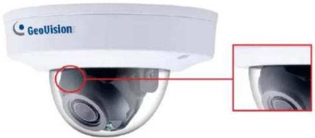
natural_image
Close-up of a GeoVision security camera with a close-up inset showing the lens and frame (no text or symbols on the device itself)Figure 1-106
Note: Make sure to adjust the lens as stated in Step 4 for any type of installation, in order for the lens to rotate smoothly upon powering up. For installation on the wall, also make sure the "UP" indicator is facing up towards the ceiling.
- Secure the transparent dome cover with the supplied torx wrench.
For Open Installation
Lead the cables out from the opening on the camera base before screwing the camera to the ceiling in Step 3.
1.5.5 Optional Installation
For optional installations, refer to 1.3.5 Optional Installation.
1.6 GV-FER5702
The IR Fisheye Rugged IP Camera is an outdoor, fixed, network camera equipped with an automatic IR-cut filter and an IR LED for day and night surveillance. The camera supports H.265 video codec to achieve better compression ratio while maintaining high quality image at reduced network bandwidths. The camera adheres to IP66 standards for dust / water protection and IK10 for metal casing and can be powered through PoE. With its WDR Pro, it can process scenes with contrasting intensity of lights and produce clear image. It is also equipped with a built-in micro SD card slot for local storage.
| Model No. | Specifications | Description | |
| GV-FER5702 | Fixed lens | Fixed Iris, f: 4.0 mm, F/1.4, M12 Lens Mount | 5 MP, H.265, Super Low Lux, WDR Pro |
1.6.1 Packing List
- IR Fisheye Rugged IP Camera (GV-FER5702)

natural_image
Close-up of a black and white electronic speaker with concentric rings (no visible text or symbols)- Drill Template Paster
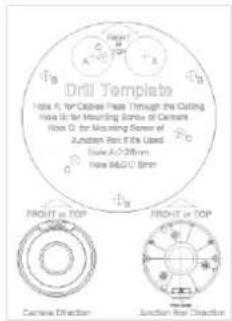
text_image
Drill Template Iowa A: for Capable Plate Through the Ceiling Hole B: for Mounting Window of Camera Hole C: for Mounting Diameter of Junction Rim #5's Laced Iowa A/C 200mm Iowa M/G/C 5mm FRONT or TOP FRONT or TOP Camera Direction Junction Rear Direction- Waterproof Rubber Set

natural_image
Product photo of four different mechanical components: a circular ring, two circular washers, and a cylindrical roller (no text or symbols visible)- Download Guide
- Screw Kit

natural_image
Five different types of screws and plastic caps arranged side by side (no text or symbols visible)1.6.2 Optional Accessories
| Model Number | Name | Details |
| GV-Mount107 (must be used with GV-Mount212P) | Pendant Bracket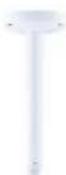 | Dimensions: ∅ 120 x 334 mm(∅ 4.72" x 13.15")Weight: 0.74 kg (1.63 lb) |
| GV-Mount212P | Wall Box Mount | Dimensions: ∅ 126 x 36 mm(∅ 5.0" x 1.4")Weight: 0.22 kg (0.48 lb) |
| GV-Mount704 (must be used with GV-Mount107) | Extension Tube | Dimensions: ∅ 3.5 x 10 or 20 or 30 or 50 cm(∅ 1.38 x 3.9 or 7.9 or 11.8 or 19.7")Weight: 225g or 360g or 500g or 780g (0.5 lb or 0.79 lb or 1.1 lb or 1.72 lb) |
| GV-PA191 | Power over Ethernet (PoE) Adapter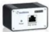 | GV-PA191 is a Power over Ethernet (PoE) adapter designed to provide power to the IP device through a single Ethernet cable. |
| GV-PoE Switch | GV-PoE Switch is designed to provide power along with network connection for IP devices. GV-PoE Switch is available in various models with different numbers and types of ports. | |
| Power Adapter | Contact our sales representatives for the countries and areas supported. | |
Note: For the restriction on installing GV-FER5702 to the wall, see Appendix I.
1.6.3 Overview
1.6.3.1 GV-FER5702
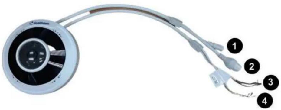
natural_image
Close-up of a medical device with attached wires and connectors, labeled 1 to 4 (no text or symbols on the device itself)Figure 1-107
| No. | Description | No. | Description |
| 1 | Power connector (DC 12V) | 3 | Green wire-Alarm output - |
| 2 | Ethernet connector / PoE | 4 | Yellow wire-Audio output |
| 3 | Brown wire-Alarm input | 4 | White wire-GND |
| 3 | Blue wire-GND | 4 | Purple wire-Audio input |
| 3 | Orange wire-Alarm output + |
Load Default Button

natural_image
Diagram of a satellite or spacecraft device showing front and side views with labeled components (no text or symbols present)Figure 1-108
| No. | Description | No. | Description |
| 1 | Load default button | 2 | SD card slot |
Note: If the default button doesn't respond after pressing for 15 seconds, reboot the camera and try again within 10 minutes of rebooting.
1.6.4 Installation
The IR Fisheye Rugged IP Camera is designed for outdoors. With the standard package, you can install the camera on the wall or ceiling. Or, you can purchase optional mounting accessories to mount your camera on a wall.
Below are the instructions for Ceiling Mount.
- Stick the drill template paster to the ceiling and drill holes on the ceiling according to the drill template.
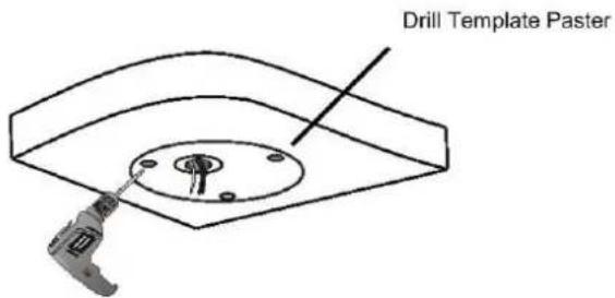
text_image
Drill Template PasterFigure 1-109
2. Insert the screw anchors.
Drill a hole to lead the cables out of the ceiling
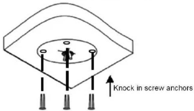
text_image
Knock in screw anchorsFigure 1-110
3. Remove the housing by turning it anticlockwise.
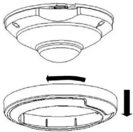
natural_image
Technical line drawing of a mechanical component with top and side views (no text or symbols)Figure 1-111
4. Secure the camera base onto the ceiling with 3 screws supplied and lock up the housing by turning it clockwise.
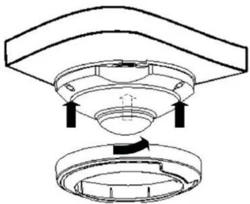
natural_image
Diagram of a ceiling fan assembly with arrows indicating direction (no text or symbols)Figure 1-112
1.6.5 Optional Installation
You can optionally purchase the following accessories to fit your mounting environment:
- GV-Mount212P for Wall Box Mount: see similar installation procedures in section 1.1.5.2.
- GV-Mount107 + GV-Mount212P for Pendant Tube Mount: see similar installation procedures in section 1.1.5.4.
1.7 GV-PTZ5810-IR
GV-PTZ5810-IR is an indoor network PTZ camera that offers 5x optical zoom, capable of showing smooth live view with great details. This camera can simultaneously deliver three video streams in resolutions up to 2880 x 1620 at 30 fps. In low-light environments, night vision is enhanced with its LEDs, which allow up to 30 m (100 ft) effective IR distance. The camera can process scenes with contrasting intensity of lights and produce clear image using the built-in WDR Pro. GV-PTZ5810-IR supports H.265 video codec to achieve better compression ratio while maintaining high quality pictures at reduced network bandwidths.
| Model No. | Specifications | Description | |
| GV-PTZ5810-IR | Motorized lens | Fixed Iris, f: 2.7 ~ 13.5 mm, F/1.2 | 5 MP, H.265, Super Low Lux, WDR Pro |
1.7.1 Packing List
- IR Mini PTZ IP Camera (GV-PTZ5810-IR)
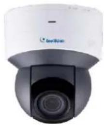
natural_image
Close-up of a white and black security camera with a circular lens (no visible text or symbols)- Drill Template Paster
- Screw Kit

natural_image
Five different types of screw and plastic adhesive packages shown side by side (no text or symbols visible)- Download Guide
1.7.2 Optional Accessories
Optional accessories can expand the capabilities and versatility of your camera. Contact your dealer for more information.
| Model Number | Name | Details |
| GV-Mount107(must be used with GV-Mount212P) | Pendant Bracket | Dimensions: 0 120 x 334 mm (0 4.72" x 13.15")Weight: 0.74 kg (1.63 lb) |
| GV-Mount211P | Wall Mount and Junction Box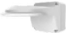 | Dimensions: 233 x 125 x 125 mm /(9.2" x 4.9" x 4.9")Weight: 1 kg (2.2 lb) |
| GV-Mount212P | Wall Box Mount | Dimensions: 0 126 x 36 mm (0 5.0" x 1.4")Weight: 0.22 kg (0.48 lb) |
| GV-Mount300-2 | Convex Corner Mount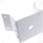 | Dimensions: 137 x 233 x 160 mm(5.4" x 9.17" x 6.3")Weight: 1.65 kg (3.64 lb) |
| GV-Mount310-2 | Concave Corner Mount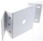 | Dimensions: 111.2 x 369.9 x 210 mm(2.6" x 11.4" x 6.6")Weight: 1.65 kg (3.64 lb) |
| GV-Mount420(must be used with GV-Mount211P) | Pole Mount Bracket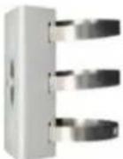 | Dimensions: 0 120 x 120 x 53.4 mm (0 4.7" x 4.7" x 2.1")Weight: 0.45 kg (0.99 lb)Steel Strap Diameter: 0 67 ~ 127 mm(0 2.6" ~ 5") |
| GV-Mount704(must be used with GV-Mount107) | Extension Tube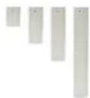 | Dimensions: 3.5 x 10 or 20 or 30 or 50 cm( 1.38" x 3.9" or 7.9" or 11.8" or x 19.7")Weight: 225 g or 360 g or 500 g or 780 g(0.5 lb or 0.79 lb or 1.1 lb or 1.72 lb) |
| GV-POE Switch | GV-POE Switch is designed to provide power along with network connection for IP devices.The GV-POE Switch is available in various models with different numbers and types of ports. | |
| Power Adapter | Contact our sales representatives for the countries and areas supported. |
1.7.3 Overview
1.7.3.1 GV-PTZ5810-IR
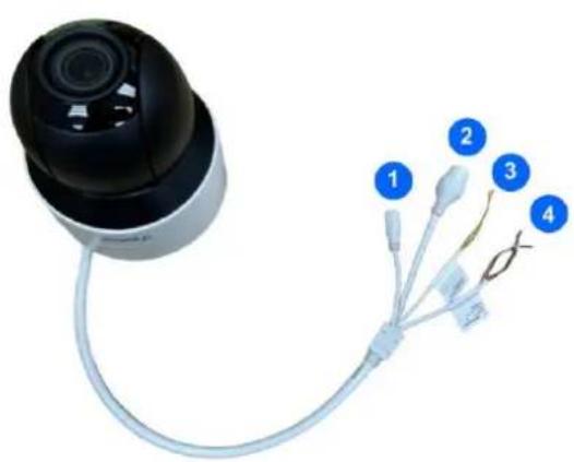
natural_image
Close-up of a black camera lens connected to a wire with four labeled connectors (no text or symbols on the device itself)
text_image
Labeled diagram of a smart security camera with numbered parts for identificationFigure 1-113
| No. | Description | No. | Description |
| 1 | Power connector (DC 12V) | 4 | Orange / white wire-Alarm output_P |
| 2 | Ethernet connector / PoE | 4 | Orange wire-Alarm output_N |
| 3 | Yellow / black wire-RS485_A | 5 | Built-in microphone |
| 3 | Yellow wire-RS485_B | 6 | IR LED |
| 4 | Purple wire-Alarm input | 7 | Built-in speaker |
| 4 | Black wire-GND | 8 | Ready LED |
Load Default Button

natural_image
Close-up of a white and black spherical device with a scroll wheel, labeled with numbers 1 and 2 (no visible text or symbols on the device itself)Figure 1-114
| No. | Description | No. | Description |
| 1 | Load default button | 2 | SD card slot |
Note: If the default button doesn't respond after pressing for 15 seconds, reboot the camera and try again within 10 minutes of rebooting.
1.7.4 Installation
The IR IP Mini PTZ Camera is designed for indoors. With the standard package, you can install the camera on the wall or ceiling. Or, you can purchase optional mounting accessories to mount your camera on a wall.
Below are the instructions for Ceiling Mount.
- Hold the camera and rotate the adapter plate counterclockwise to detach it from the camera.
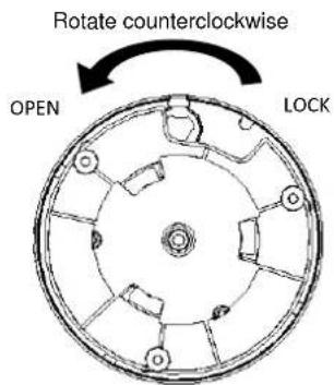
text_image
Rotate counterclockwise OPEN LOCKFigure 1-115
- Stick the drill template paster to the ceiling and drill holes on the ceiling according to the drill template.

text_image
Drill Template PasterFigure 1-116
- Fix the adapter plate to the ceiling with screws.

text_image
Technical diagram of a mechanical assembly with labeled components and motion indicatorsFigure 1-117
- Secure the camera to the adapter plate and rotate the camera counterclockwise until it's fastened.

natural_image
Diagram of a smart air conditioner unit with rotating control panel and fan (no text or symbols)Figure 1-118
1.7.5 Optional Installation
You can optionally purchase the following accessories to fit your mounting environment:
- GV-Mount107 + GV-Mount212P for Pendant Tube Mount: see similar installation procedures in section 1.1.5.4.
- GV-Mount211P / GV-Mount212P for Wall Box Mount: see section 1.1.5.1 and 1.1.5.2.
• GV-Mount300-2 / 310-2 for Corner Mount: see Appendix F. GV-Mount300-2 / 310-2.
• GV-Mount420 + GV-Mount211P for Pole Box Mount: see section 1.1.5.3.
1.8 System Requirements
| CPU | Intel Core i5-4670, 3.40 GHz |
| Memory | DDR3 8 GB RAM |
| On Board Graphics | Intel HD Graphics 4600 (Versions of driver from year 2014 or later required) |
| Web Browsers | ● Internet Explorer 11.0 or above● Google Chrome● Microsoft Edge● Mozilla Firefox● Safari |
| Note:1. Some functions are not available on non-IE browsers, e.g., Local Parameters (see 3.1.2 Local Parameters) and Photo (see 3.7.3 Backing Up Storage) are not supported by Google Chrome.2. Only H.264 codec is supported for live view on non-IE browsers. | |
1.9 Waterproofing the Cable
Waterproof the Ethernet cable by using the supplied waterproof rubber set.
- Attach the seal ring to the RJ-45 plug.
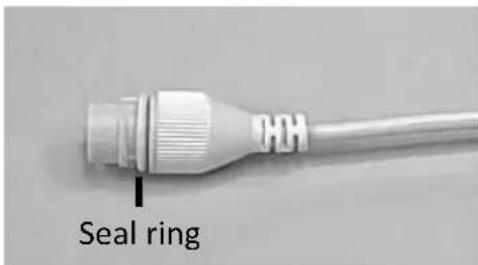
text_image
Seal ringFigure 1-119
- Insert the waterproof components through the Ethernet cable as shown below.
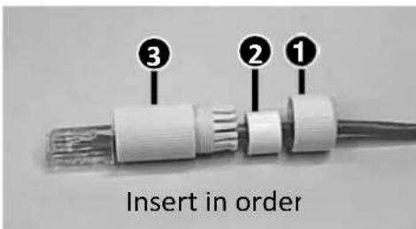
text_image
Insert in orderFigure 1-120
- Insert the cylindrical waterproof ring into waterproof bolt.
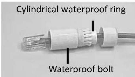
text_image
Cylindrical waterproof ring Waterproof boltFigure 1-121
- Insert the cable into the RJ-45 plug and screw the waterproof bolt in.
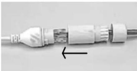
natural_image
Close-up of a white electrical plug with internal components and a black arrow pointing to one end (no text or symbols visible)Figure 1-122
- Screw in the waterproof bolt lid.
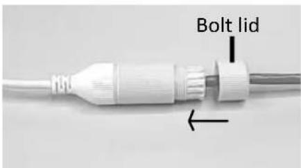
text_image
Bolt lidFigure 1-123
- Finish the waterproof installation.
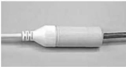
natural_image
Close-up of a white plastic electrical plug with a metallic end cap (no text or symbols visible)Figure 1-124
- If the camera has a DC cable and is not in use, you can waterproof it by inserting the supplied plug into the DC interface.
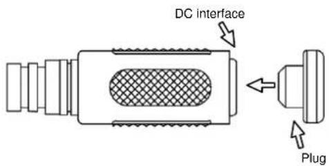
text_image
DC interface PlugFigure 1-125
IMPORTANT: After installing the camera, it is required to use waterproof tapes to cover and protect any of the tail cables and connection points that are exposed, see Note for Installing Camera Outdoor at the beginning of the manual.
Chapter 2 Accessing the Camera
Once installed, the IP camera is accessible on a network. Follow these steps to configure the network settings and access your surveillance images.
2.1 Installing on a Network
These instructions describe the basic connections to install the camera on the network.
- Using a standard network cable, connect the camera to your network.
-
Connect to power using one of the following methods:
-
Use the optional power adapter to connect to power.
-
Use the Power over Ethernet (PoE) function in which power is supplied over the network cable.
-
You can now access the Web interface of the camera.
-
If the camera is installed in a LAN with DHCP server, use GV-IP Device Utility to look up the camera's dynamic IP address. See 2.1.1 Looking up the Dynamic IP Address and Logging In.
- If the camera is installed in a LAN without DHCP server, the default IP address 192.168.0.10 is applied. To assign a different static IP address, see 2.1.2 Configuring the IP Address.
Note: You must set your browser to allow ActiveX Control and perform a one-time installation of the ActiveX component onto your computer upon your first login.
2.1.1 Looking Up the Dynamic IP Address and Logging In
By default, when the device is connected to LAN with a DHCP server, it is automatically assigned with a dynamic IP address. Follow the steps below to look up its IP address and log in the Web interface.
- Download and install the GV-IP Device Utility program from the company website.
Note:
- The PC installed with GV-IP Device Utility must be under the same LAN as the camera you wish to configure.
-
By default, the Administrator's username is admin and cannot be modified.
-
On the GV-IP Device Utility window, click the button to search for the IP devices connected in the same LAN. Click the Name or Mac Address column to sort.
-
Find the camera with its Mac Address, click on its IP address.

text_image
IP Device Utility File Tool Version User Guide General settings Name Mac Address IP Address Firmware Version NOTE 1 GV-AD4710 0013E2F7D40A 192.168.0.101 v1.04 2020-05-27 Please change your default password! 2 GV-ABL2702 0013E2F7F780 192.168.0.102 v1.04 2020-05-27 Please change your default password! 3 GV-ABL4703 0013E21DC232 192.168.0.103 v1.02 2020-05-27 Please change your default password! 4 Switch 10F013F1683B 192.168.0.249 v1.00 2020-03-30 GVAPDE1611Figure 2-1
- For the first-time users, you will be requested to set up a password.
- Type a new password and click OK.
- Type your username and password on the login page and click Login.
2.1.2 Configuring the IP Address
By default, when the device is connected to LAN without a DHCP server, it is assigned with a static IP address of 192.168.0.10. Follow the steps below to assign a new IP address to avoid IP conflict with other GeoVision devices.
- Open your Web browser and type the default IP address 192.168.0.10.
- Type your username and password. Click Login.
- Click Setup, select Common in the left menu and select Network.

text_image
GeoVision Live View Playback Photo Setup Common Basic Info Local Parameters ► Network Time Server OSD User Network Video & Audio PTZ Image Intelligent Events Network Obtain IP Address Static IP Address 192.168.1.48 Subset Mask 255.255.248.0 Default Gateway 192.168.0.1 IPv6 IPv6 Mode Manual IPv6 Address Prefix Length 64 Default Gateway MTU 1500 Port Type FE Port Operating Mode Auto-negotiation SaveFigure 2-2
- Select Static IP from the Obtain IP Address drop-down list.
- Enter the IP address, subnet mask, and default gateway address. Make sure that the IP address of the camera is unique in the network.
- Click Save.
Note: When you are changing the network segment through the Web interface or GV-IP Device Utility, it is required that you change the default gateway, too, for the change to take effect.
2.2 Accessing Live View
After logging into the camera, you will see the Home page as shown below:
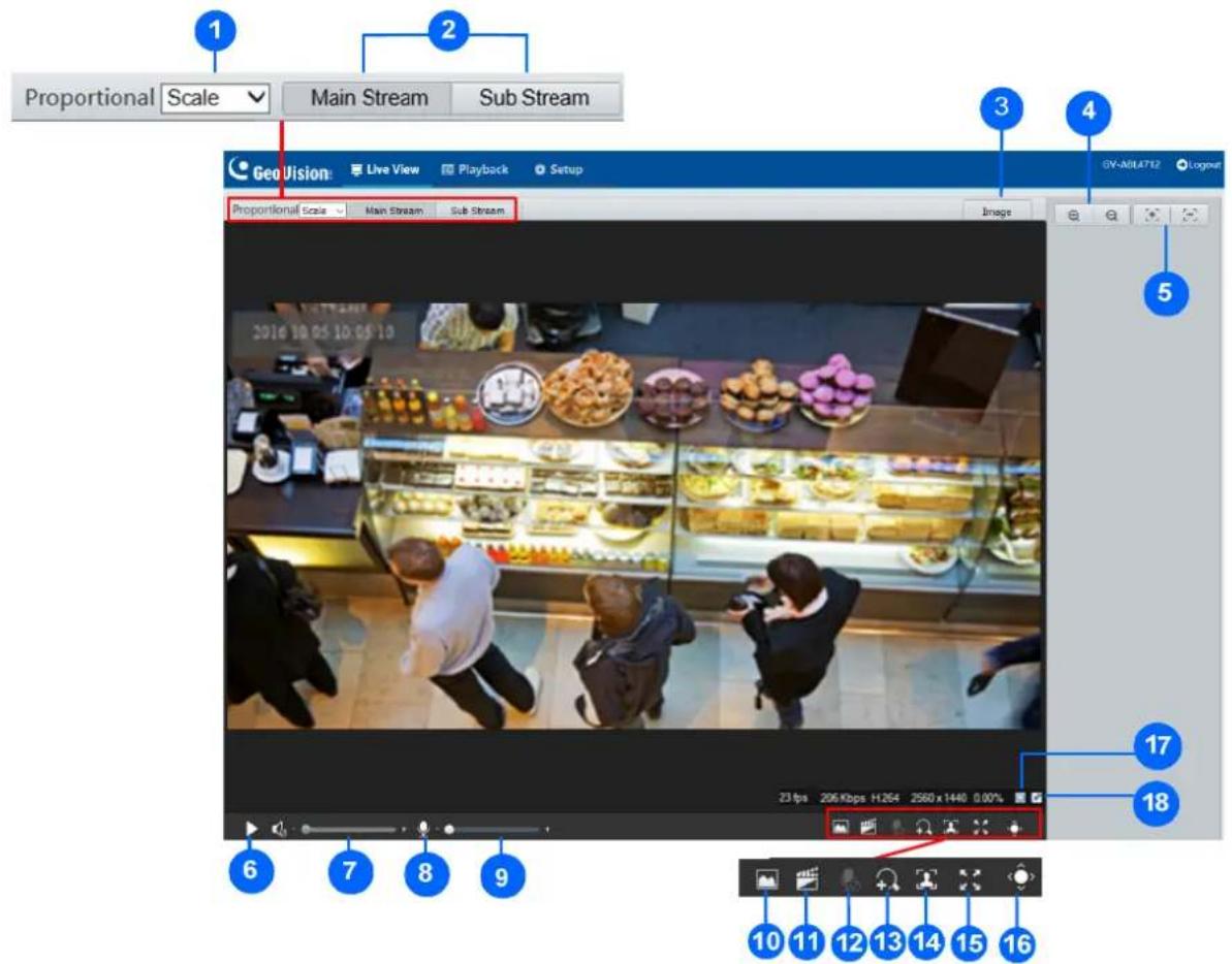
text_image
Proportional Scale Main Stream Sub Stream Geo Vision Live View Playback Setup Image GY-ABL4712 Lognut Proportional Scale Main Stream Sub Stream 2016 10:05 10:05:10 23 fps 206 Kbps H264 2560 x 1440 0.00% 17 18 6 7 8 9 10 11 12 13 14 15 16Figure 2-3
| No. | Name Function | |
| 1 | Proportional | Set the display ratio of the image.Scale: display images by 16:9.Stretch: display images by window size.Original: display images in its original size. |
| 2 | Live Stream | Select a live video stream: main stream, sub stream or third stream (when enabled). |
| 3 | Image | Open the image setting page. – See 3.5.1 Image. |
| 4 | Zoom +/- | Only formodelswith motorized varifocal lens, increaseordecreasethe camera’s optical zoom. |
| 5 | Focus +/- | Only formodelswith motorized varifocal lens, increaseordecreasethe camera focus. |
| 6 | Play/Stop Play or stop live video. | |
| 7 | Video Volume | Only for theaudio-supporting models, adjust the audio output volume on the PC. |
| 8 | Microphone | Only foraudio-supporting models, enableor disablemicrophone. |
| 9 | Microphone Volume | Only foraudio-supporting models, adjust the microphone volume on the PC during audio communication between the PC and the camera. |
| 10 | Snapshot Take a snapshot of the current image displayed on the PC. | |
| 11 | Local Recording Start or stop local recording. | |
| 12 | Two-way Audio | Only fortwo-way-audio-supporting models, startor stoptwo-way audio. |
| 13 | Digital Zoom | Enableor disabledigital zoom.- See 2.2.1 Digital Zoom. |
| 14 | Face Snapshot | Only forface-snapshot-supporting models, startor stopface snapshot.By activating this function, the camera takes face snapshots, and displays them on the right of the live view window. Before activating this function, you must enableFace Detection- See 3.6.1.7 Face Detection. |
| 15 | Full Screen Display in full screen mode. | |
| 16 | Control Panel | Only formodels with motorized varifocal lens, hide or show the camera's optical zoom and focus functions. |
| 17 | Reset the packet loss rate to zero. | |
| 18 | Click to always display packet loss rate and bit rate information at the bottom. Click again to restore to only displaying the information for 3 seconds when the mouse cursor is moved onto the live view. | |
| Note:1. The paths for saving snapshots and local recordings are set in Local Settings. See 3.1.2 Local Parameters.2. The No. 17 and 18 buttons will appear on the floating toolbar when you move the mouse cursor onto the live view. | ||
2.2.1 Digital Zoom
To use the digital zoom function, follow these steps:
- Click 🖱️ (No. 13, Figure 2-4) on the toolbar.
- Click and drag the mouse button in any direction to specify an area.
- To restore the original image size, right click on the enlarged area.
- To exit, click 🧀️ (No. 13, Figure 2-4) on the toolbar.
2.2.2 Start Recording
For models with local storage, you can start/stop recording manually or by schedule. At the top of Home page, select Setup, select Storage in the left menu and select Storage. For details, see 3.8.1 Formatting Storage.

text_image
Storage Storage Medium Memory Card Format Enable Storage Medium Status: Normal Total Capacity 60790 MB, Free Space 60790 MB. Allocate Capacity Video(MB) 51672 (The remaining capacity is used for image storage.) Common Snapshot(MB) 9118 (The remaining capacity is used for Face snapshot storage.) Face Snapshot(MB) 0 Video Storage Info Storage Policy Manual and Alarm Recording Scheduled and Alarm Recording Alarm Recording Only When Storage Full Overwrite Stop Post-Record(s) 60 SaveFigure 2-4
2.3 PTZ Control Panel
In this section, you will be guided through the various functions of PTZ Control Panel. The PTZ Control Panel is accessed from the live view interface of the camera.
Note this is only applicable to GV-PTZ5810-IR.
2.3.1 Accessing the PTZ Control Panel

text_image
Scene Lock Preset PatrolFigure 2-5
| No. | Item Function | |
| 1 | Auto Pan Start or stop | auto panning of the camera. |
| 2 | PTZ Control Panel | Control the direction of the camera and release the control. |
| 3 | PTZ Speed | Adjust the moving speed of the PTZ camera. |
| 4 | Zoom | Adjust the camera's zoom (optical). |
| 5 | Focus | Adjust the camera's focus. |
| 6 | Screen Lock Lock or | unlock the camera direction. |
| 7 | Preset | Select a preset and the camera goes to the selected preset. -- See 2.3.2 Setting Presets. |
| 8 | Patrol | Select a patrol route. -- See 2.3.3 Setting Patrol. |
2.3.2 Setting Presets
You can create and delete preset points by clicking Preset on the control panel of Live View.
Adding a Preset
- Select Preset on the control panel, and adjust the camera view to the desired direction, zoom and focus.

text_image
Preset Patrol Add Preset Preset No. Preset Name OK CancelFigure 2-6
- Click the Add button to add it as a preset.
- Type a number and name for the preset and click OK.
Going to a Preset
On the control panel, click for a preset. The PTZ camera goes to the selected preset.
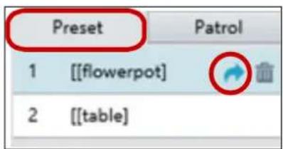
text_image
Preset 1 [[flowerpot]] 2 [[table]Figure 2-7
Deleting a Preset
On the control panel, click for a preset and confirm the delete.

text_image
Preset 1 [[flowerpot]] 2 [[table]Figure 2-8
2.3.3 Setting Patrol
A patrol route is the track by which the camera follows when moving from a preset to the next. The length of time that the camera stays at each preset is configurable. Multiple patrol routes are allowed for the camera.
Patrol actions include going to a preset and staying at the preset for a certain amount of time before going to the next. You can set the rotation direction, zoom, rotation speed, patrol time, and stay time. You can also record a route and add it to the action list.
Note: To enable Preset Snapshot, see 3.4.5 Patrol.
To access the Patrol functions, click Patrol on the control panel of Live View.
Adding a Patrol Route
- On the control panel, click the Add button + to add a patrol route.
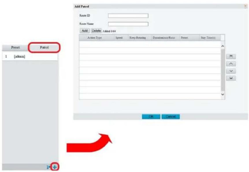
text_image
Add Patrol Route ID Route Name: Add Delete Added 0-04 Action Type Speed Keep Rotating Duration/Time Ratio Preset Stop Time(s) 1 [admin] OK CancelFigure 2-9
- On the Add Patrol page, type the desired route ID and name.
- Click Add to add a patrol action. Use the buttons to adjust the sequence of the actions and click OK.
Note:
- It is recommended that the first action type is Go to Preset.
- If Keep Rotating is selected, the camera will rotate at the set speed and zoom in the set direction or position for a certain amount of time.
Starting a Patrol Route
After you have added a patrol route, you can start patrolling by clicking ▶ on the control panel.
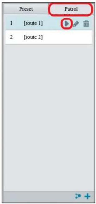
text_image
Preset 1 [route 1] 2 [route 2] PatrolFigure 2-10
Editing a Patrol Route
On the control panel, click to modify the ID, name and movement of an existing patrol route.

text_image
Preset 1 [route 1] 2 [route 2] patrol Route ID 3 Route Name: route 1 Add Delete Added 1-44 Active Type Speed Keep Running Desimacy Ratio Press Buy Data(0) Cota Preset 5 (Padmit) 800 OK CancelFigure 2-11
Delete a Patrol Route
On the control panel, click for a patrol route and confirm the delete.

text_image
Preset Patrol 1 [route 1] 2 [route 2]Figure 2-12
Making a Patrol Plan
You can set up the camera to perform different patrol routes at different time periods throughout the week by making a patrol plan.
- On the control panel, click the Patrol Plan button to set the correct patrol time and route.
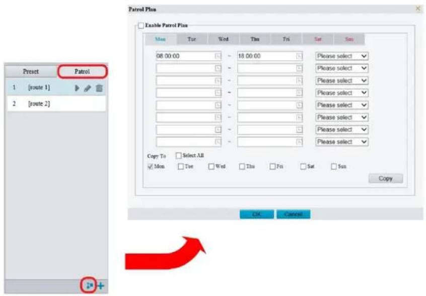
text_image
Preset Patrol 1 [route 1] 2 [route 2] Enable Patrol Plan Mon Tue Wed Thu Fri Sat Sun 08:00:00 18:00:00 Please select Please select Please select Please select Please select Please select Please select Please select Please select Copy To Select All Mon Tue Wed Thu Fri Sat Sun Copy OK CancelFigure 2-13
- Select Enable Patrol Plan.
- Click OK.
2.4 Playing Back Recorded Videos
Note this function is only applicable to models with SD card slot for local storage.
To play back recorded videos from the camera's local storage, click Playback at the top of the Web interface.

text_image
GeoVision Live View Playback Setup UV 18LIA/71 Logout 1 2 3 4 5 6 7 8 9 Pre-coding Downset Query Results 1819:34 - 18:07:15 1837:13 - 18:54:46 1854:48 - 18:52:25 1812:25 - 18:29:56 1829:58 - 18:47:30 1847:32 - 20:09:05 2006:07 - 20:22:40 2022:42 - 20:40:15 2040:17 - 20:57:49 2050:04 - 20:57:35 2057:53 - 21:15:24 2115:26 - 21:32:59 2133:03 - 21:49:18 2207:37 - 22:25:09 2225:11 - 22:30:59 2237:15 - 22:37:27 2238:23 - 22:39:05Figure 2-14
| No. | Name Function | |
| 1 | Date | Select the date of the video to playback. |
| 2 | Recording Download | Select to download a recorded video from the camera's local storage. See 2.3.1 Recording Download for details. |
| 3 | Query | Click Query to show the list of recorded videos of the date specified. |
| 4 | Playback Play back the recorded video selected. | |
| 5 | Stop Stop playback of the recorded video selected. | |
| 6 | Snapshot Take a snapshot of the current playback image displayed. | |
| 7 | Digital Zoom | Enable 🎨 or disable 🎨 digital zoom. – See 2.2.1 Digital Zoom. |
| 8 | Volume Adjust the audio output volume on the PC. | |
| 9 | Timeline Users can select the desired time to play back the video from | |
Note: To store and play back recorded videos to and from the camera's local storage, make sure to configure the storage settings in Storage. For details, refer to 3.7.1 Formatting Storage.
2.4.1 Recording Download
To download recorded videos from the local storage, follow the steps below:
- Click Recording Download (No. 2, Figure 2-14) on the right of the Playback window.

text_image
Recording Download Recording Time 2017-09-13 ~ 2017-09-14 Search No. Start Time End Time ○ 1 2017-09-13 19:12:23 2017-09-13 19:29:56 ○ 2 2017-09-13 19:29:58 2017-09-13 19:47:30Figure 2-15
- Search for video within a specified time period. The results are shown in a list.
- Select your video and click Download to download a video to your local path from the local storage.
- Click Open to show the folder in which the downloaded videos are saved.
Chapter 3 Administrator Mode
The Administrator can access and configure the GV-IP Camera through the network. Click Setup at the top of the Web interface to access the following configuration tabs: Common, Network, Video & Audio, Image, Intelligent, Events, Storage, Security and System.

text_image
GeoVision Live View Playback Photo Setup Common Basic Info Basic Info Model GV-AVD2700 Firmware Version V1.04_2020_04_23 Hardware Version A Boot Version V2.0 Serial No. 210215T88L3186000029 Network 192.168.5.220/255.255.248.0 192.168.0.1 MAC Address 00.13:e2.f7:f8.3b Status System Time 2020-5/13 16:35:27 Operation Time 6 Day(s) 6 Hour(s) 40 Minute(s) Refresh Common Configurations Network Time OSD UserFigure 3-1
List of Options
See the table below for the settings available on the Web interface. Find the topic of interest by referring to the section number prefixed to each option.
IMPORTANT: The available functions may vary among camera models and firmware versions.
| 3.1 Common | 3.1.1 Basic Info3.1.2 Local Parameters |
| 3.2 Network | 3.2.1 Network3.2.2 DNS3.2.3 Port3.2.4 DDNS3.2.5 E-mail3.2.6 SNMP3.2.7 802.1x3.2.8 QoS |
| 3.3 Video & Audio | 3.3.1 Video3.3.2 Snapshot3.3.3 Audio3.3.4 ROI3.3.5 Media Stream |
| 3.4 PTZ | 3.4.1 Basic Settings3.4.2 Home Position3.4.3 Limit3.4.4 Remote Control3.4.5 Patrol3.4.6 Orientation |
| 3.5 Image | 3.5.1 Image3.5.2 OSD3.5.3 Privacy Mask |
| 3.6 Intelligent | 3.6.1 Smart Settings3.6.2 Advanced Settings |
| 3.7 Events | 3.7.1 Motion Detection3.7.2 Tampering Alarm3.7.3 Audio Detection3.7.4 Alarm Input3.7.5 Alarm Output3.7.6 One-Key Shielding Linkage |
| 3.8 Storage | 3.8.1 Formatting Storage3.8.2 FTP3.8.3 Backing Up Storage |
| 3.9 Security | 3.9.1 User3.9.2 Network Security |
| 3.10 System | 3.10.1 Time3.10.2 Server3.10.3 Maintenance3.10.4 Network Diagnosis3.10.5 Log3.10.6 Ports and Devices |
3.1 Common
Under the Common tab, the Administrator can find the general settings of the camera, as well as shortcuts to the following setting pages.
■ Network: See 3.2.1 Network for details.
■ Time: See 3.9.1 Time for details.
■ OSD: See 3.4.2 OSD for details
■ User: See 3.8.1 User for details
3.1.1 Basic Info
You can view the current status of your camera. Click Refresh for the latest status information. Under Common Configuration on the right, you can click on the icons to quickly access the corresponding configuration pages.

text_image
Basic Info Basic Info Model GV-AVD2700 Firmware Version V1.04_2020_04_23 Hardware Version A Boot Version V2.0 Serial No. 210235T88L3186000029 Network 192.168.5.220/255.255.248.0/192.168.0.1 MAC Address 00:13:e2:f7:f8:3b Status System Time 2020/5/7 17:27:08 Operation Time 0 Day(s) 7 Hour(s) 32 Minute(s) Refresh Common Configuration Network Time OSD OSD UserFigure 3-2
3.1.2 Local Parameters
You can set the local parameters for your PC.

text_image
Local Parameters Smart Intelligent Mark Enable Video Display Mode Balanced Protocol TCP Audio Encoding Format G.711U Recording and Snapshot Recording Subsection By Time Subsection Time (min) 30 When Storage Full ● Overwrite Recording ○ Stop Recording Total Capacity(GB) 10 Local Recording TS Files Folder C:\Users\User\Surveillance_IPC\IPCNB Browse... Open SaveFigure 3-3
[Smart / Intelligent Mark]
■ Intelligent Mark: Enabled by default to display the detection line or area as defined by Smart Settings. See details in 3.6.1 Smart Settings.
■ Untriggered Target: When enabled, an on-screen mark will display on the target and track it as defined by Smart Settings on Live View. You must set up Smart Settings first for this function to work, see 3.6.1 Smart Settings (not applicable to GV-BLFC5800 / EBFC5800).
[Video]
■ Processing Mode
- Real-Time Priority: Select this if the network is in good condition.
- Fluency Priority: Select this if you want short time lag for live video.
- Ultra-low Latency: Select this if you want the minimum time lag for live video.
■ Display Mode: Set the display mode according to the network status, including Min.
Delay, Balanced Delay, and Fluent Delay for low to high delay. Or customize the display mode parameters by selecting Customize / Custom.
■ Protocol: Select the protocol used to transmit media streams to be decoded by the PC.
[Audio] This function is only applicable to audio-in-supporting models.
■ Encoding Format: Select the format used to encode audio.
Note: The Video and Audio functions are not applicable to GV-ABL2701 series / 2703 series / 4701 series / 4703, GV-ADR2701 / 2702 / 4701 / 4702, GV-TBL2703 series / 4700 / 4703, TDR2702 series / 4702 series, and GV-TVD4700. For GV-TDR2704 / 4704, only the Audio function is not applicable.
[Recording and Snapshot]
■ Recording
- Subsection by Time (1\~60): Set a maximum time length of each recording file. If you select 5 minutes, a 30-minute event will be chopped into six 5-minute event files.
- Subsection by Size: Set a maximum size limit of each recording file.
■ When Storage Full
- Overwrite Recording: When the assigned storage space on the computer is full, the camera deletes the oldest existing recording files to make room for the new ones.
- Stop Recording: When the assigned storage space on the computer is full, recording stops automatically.
■ Total Capacity (1\~1024): Set a capacity limit to the assigned storage space on the computer.
■ Files Folder: Click Browse to set a folder to store the recorded videos and captured snapshots at your local computer.
3.2 Network
The network section allows you to configure the network settings, modify ports, configure FTP server, and set up e-mail for notification.
3.2.1 Network

text_image
Network Obtain IP Address Static IP Address 192.168.5.220 Subnet Mask 255.255.248.0 Default Gateway 192.168.0.1 IPv6 IPv6 Mode Manual IPv6 Address Prefix Length 64 Default Gateway MTU 1500 Port Type FE Port Operating Mode Auto-negotiation SaveFigure 3-4
■ Obtain IP Address: Select Static IP or DHCP according to your network environment.
Static IP address: Assign a static IP or fixed IP to the camera. Type the camera's IP address, Subnet Mask and Router/Gateway.
| Parameters | Default |
| IP address | 192.168.0.10 |
| Subnet Mask | 255.255.255.0 |
| Router/Gateway | 192.168.0.1 |
- PPPoE: The network environment is xDSL connection. Type the Username and Password provided by ISP to establish the connection. If you use the xDSL connection with dynamic IP addresses, first use the DDNS function to obtain a domain name linking to the camera's changing IP address.
- DHCP: The network environment has a DHCP server which will automatically assign a dynamic IP address to the camera. You can look up the current IP address using GV-IP Device Utility.
■ IPv6: Type the camera's IPv6 Address and Default Gateway. Optionally change the Prefix Length according to your network settings.
■ MTU: Type the Maximum Transfer Unit (MTU). The default value is 1500.
■ Operating Mode: Select a mode to control the bandwidth.
Note:
- IPv6 is currently unsupported.
- You can also configure Network under Common for GV-BLFC5800, EBD4700 / 8711, EBFC5800, TBL2705 / 4700 / 4710 / 8804, TDR 2700 / 2704 / 8805, and TFD4800.
3.2.2 DNS
Type the camera's Preferred DNS Server and Alternate DNS Server.

text_image
DNS Preferred DNS Server 8.8.8.8 Alternate DNS Server 8.8.4.4 SaveFigure 3-5
3.2.3 Port
Port
You can modify the default HTTP, HTTPS and RTSP ports if necessary.
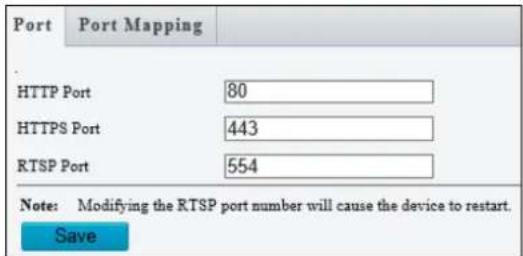
text_image
Port Port Mapping HTTP Port 80 HTTPS Port 443 RTSP Port 554 Note: Modifying the RTSP port number will cause the device to restart. SaveFigure 3-6
Port Mapping
This function can automatically forward and open certain ports on your router, allowing connection to your camera from the Internet.
- Enable Port Mapping, and select UPnP or Manual for Mapping Type.
- If you select UPnP, select between Auto and Manual to have the router automatically configure the external ports or manually configure the external ports. If the configured port is occupied, the Status will show inactive.
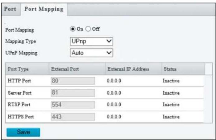
text_image
Port Port Mapping Port Mapping On Off Mapping Type UPnp UPnP Mapping Auto Port Type External Port External IP Address Status HTTP Port 80 0.0.0.0 Inactive Server Port 81 0.0.0.0 Inactive RTSP Port 554 0.0.0.0 Inactive HTTPS Port 443 0.0.0.0 Inactive SaveFigure 3-7
- If you select Manual, configure external ports. External IP is applied to the camera automatically.
- Click Save.
Note: For this function to work, your router needs to support port forwarding.
3.2.4 DDNS
DDNS (Dynamic Domain Name System) provides a convenient way of accessing the camera when using a dynamic IP. DDNS assigns a domain name to the camera, so that the Administrator does not need to go through the trouble of checking if the IP address assigned by DHCP Server or ISP (in xDSL connection) has changed.

text_image
DDNS DDNS Service On Off DDNS Type GeoDDNS Register DDNS Server http://ns.gvdip.com/register.aspx Username geovision Password •••••••• Confirm •••••••• SaveFigure 3-8
- Click On to enable DDNS Service.
- Select the DDNS service provider you have registered with. If you choose DynDNS, skip to Step 5.
- Copy the website address http://ns.gvdip.com/register.aspx to a browser to access Geovision DDNS service.
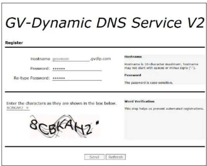
text_image
GV-Dynamic DNS Service V2 Register Hostname geovision ____,gvdlp.com Password: ****** Re-type Password: ****** Hostname Hostname is 16-character maximum; hostname may not start with spaces or minus signs (*-§). Password The password is case-sensitive. Enter the characters as they are shown in the box below. 8CBKAH2 * Word Verification This stop helps us prevent automated registrations. Send RefreshFigure 3-9
- In the Geovision DDNS Server page, type a desired Hostname and Password. Re-type Password and type the verification letters shown in the image. Click Send.
- In the Web interface of your camera, type Username. The username is the hostname registered in DDNS Server.
- Type Password, and Confirm Password.
- Click Save.
After the DDNS is successfully configured, a notification bar will be displayed as shown in Figure 3-10. Next time when you log in the camera, type the domain name like this: (hostname).gvdip.com; for example, geovision.gvdip.com.

text_image
Live View Playback Setup Parameter(s) set successfully. DDNS DDNS Service On Off DDNS Type GeoDDNS Register DDNS Server http://ns.gvdip.com/register.aspxFigure 3-10
3.2.5 E-mail
After the configuration of E-mail, you will be able to send messages to the specified E-mail addresses when alarms are triggered.
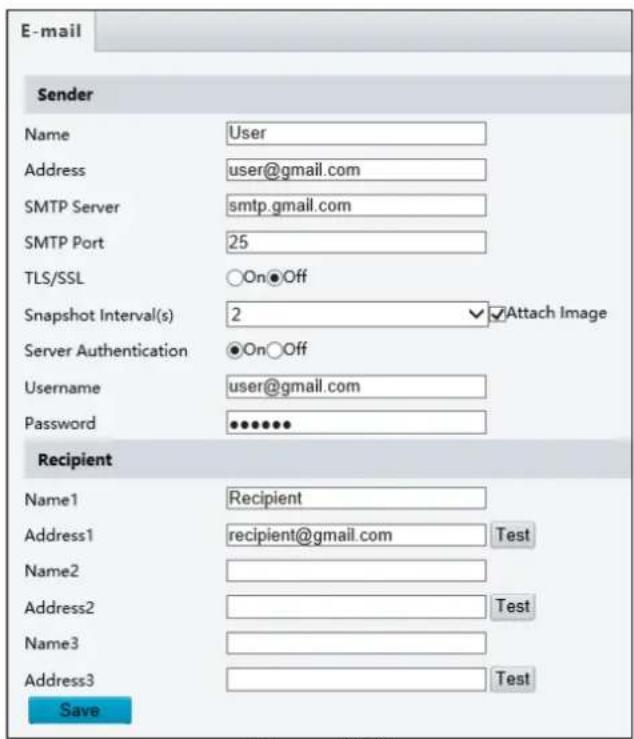
text_image
E-mail Sender Name User Address user@gmail.com SMTP Server smtp.gmail.com SMTP Port 25 TLS/SSL ○On●Off Snapshot Interval(s) 2 ✓ Attach Image Server Authentication ●On○Off Username user@gmail.com Password ••••••• Recipient Name1 Recipient Address1 recipient@gmail.com Test Name2 Address2 Test Name3 Address3 Test SaveFigure 3-11
- Type the Name and Address of the sender.
- Type the SMTP Server.
- Type the SMTP Port number.
- To send the e-mail through TLS / SSL encryption, enable TLS/SSL.
- Enable Attach Image to include 3 instant snapshots as attachment in the e-mail according to the Snapshot Interval specified.
- If the SMTP Server needs authentication, enable Server Authentication and type a valid username and password to log in the SMTP server.
- Type the name(s) and e-mail address(s) of the Recipient(s).
- Click Save.
Note: To send snapshots to the specified E-mail addresses, make sure to enable the Snapshot function. For more detailed instructions, refer to 3.3.2 Snapshot.
3.2.6 SNMP
Users can transfer the configurations of the device through SNMP protocol to communicate with and/or integrate it into a central server. Note this function is NOT supported by GV-ABL2701 series / 2703 series / 4703 / 4711, GV-ADR2701 / 2702 / 4702, GV-EBD4701 / 4712, GV-TBL2703 series / 4700 / 4703 / 4711, GV-TDR2702 / 4702 / 4703 series, GV-TFD4700, and GV-TVD4700 / 4711.
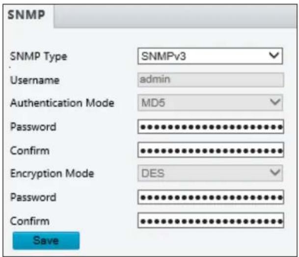
■ SNMP Type: Select the type of SNMP desired, between SNMPv3 and SNMPv2.
■ Authentication Mode: Define a desired password for authentication between the device and the central server.
■ Encryption Mode: Define a desired password for encryption that needs to be matched by the central server.
Click Save for the changes to take effect.
3.2.7 802.1x
IEEE 802.1x is an IEEE standard for port-based Network Access Control. It provides an authentication mechanism to devices wishing to attach to a LAN or WLAN. Note this function is only applicable to GV-ABL2702 / 4712 / 8712, GV-AVD2700 / 4710 / 8710, GV-BLFC5800, GV-EBD2702 / 4700 / 4704 / 4711 / 4813 / 8700 / 8711 / 8800 / 8813, GV-EBFC5800, GV-FER5702, GV-PTZ5810-IR, GV-TBL4705 / 4710 / 4810 / 8710 / 8804 / 8810, GV-TDR2700 / 4700 / 4704 / 4803 / 8805, TFD4800, and GV-TVD4710 / 4810 / 8710 / 8810.
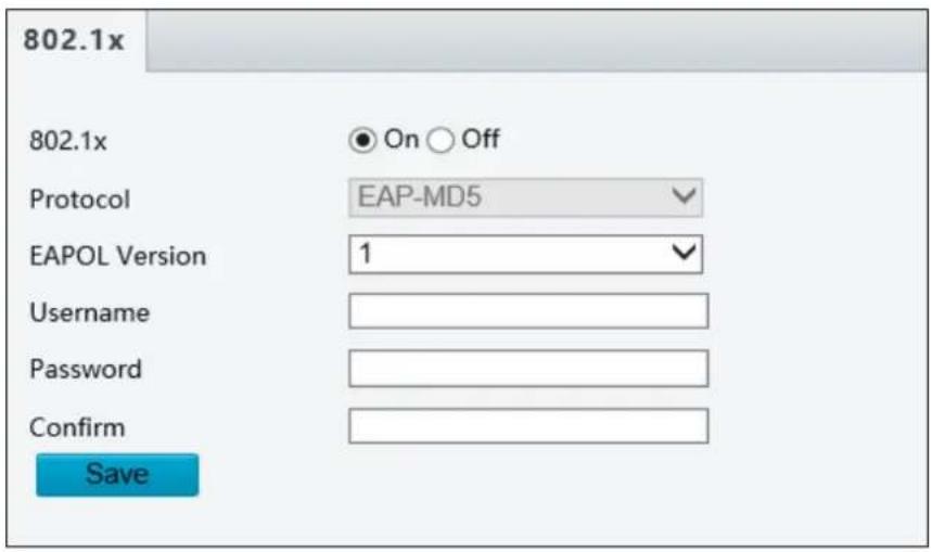
text_image
802.1x 802.1x On Off Protocol EAP-MD5 EAPOL Version 1 Username Password Confirm SaveFigure 3-13
- Enable IEEE 802.1x.
- Type the Username and Password. Type the password again for confirmation.
- Click Save.
Note: For this function, your network environment needs to support 802.1x.
3.2.8 QoS
QoS is the prioritization of network traffic used to ensure resource reservation under abundant data flow. Note this function is NOT supported by GV-ABL2701 series, GV-ADR2701, GV-EBD4701 / 4712, GV-TDR4703 series, and GV-TFD4700.

text_image
QoS Audio & Video 46 Alarm Report 0 Configuration Management 0 FTP 4 SaveFigure 3-14
■ Audio & Video: Optionally modify the priority of value of Audio & Video. The higher the value, the higher the priority.
■ Alarm Report: Optionally modify the priority of value for Alarm Report. The higher the value, the higher the priority.
■ Configuration Management: Optionally modify the priority for Configuration Manager. The higher the value, the higher the priority.
■ FTP: Optionally modify the priority of value for FTP. The higher the value, the higher the priority.
Click Save the apply the QoS settings configured.
3.3 Video & Audio
This section allows you to configure the three video streams and audio input. The audio function is only applicable to GV-ABL2702 / 4711 / 4712 / 8712, GV-AVD2700 / 4710 / 8710, GV-BLFC5800, GV-EBD2702 / 2704 / 4701 / 4704 / 4711 / 4712 / 8711 / 8800 / 8813, GV-EBFC5800, GV-FER5702, GV-PTZ5810-IR, GV-TBL4705 / 4710 / 4711 / 8710 / 8804 / 8810, GV-TDR4703 series / 8805, and GV-TFD4700 / 4800, GV-TVD4710 / 4711 / 8810.
3.3.1 Video
You can set video parameters that your camera supports. You may also enable the sub-stream and third stream as needed. The third stream is disabled by default.

text_image
Video Capture Mode 2880×1620@30 Main Stream Video Compression H.265 Resolution 2880×1620 Frame Rate(fps) 30 Bit Rate(Kbps) 3072 Bitrate Type VBR Image Quality Bit Rate Quality I Frame Interval 60 GOP IP Smoothing Clear Smooth Smart Encoding Off Enable Sub Stream Video Compression H.264 Resolution 640×360 Frame Rate(fps) 30 Bit Rate(Kbps) 1024 Bitrate Type VBR Image Quality Bit Rate Quality I Frame Interval 60 GOP IP Smoothing Clear Smooth Smart Encoding Off SaveFigure 3-15
■ Capture Mode: Sets the resolution of Main Stream and the maximum frame rate allowed.
Note: The Resolution under Main Stream will change according to the resolution selected for Capture Mode.
The following options are available for the main, sub and third streams.
■ Video Compression: Set the codec type to H.265, H.264 or MJPEG.
■ Resolution: Select different resolutions for each stream.
Note:
- Changing the resolution in this option will not affect the Capture Mode.
- For GV-ABL4711, GV-EBD4701 / 4712, GV-TBL4700 / 4711, GV-TDR4703 series, GV-TFD4700, and GV-TVD4700 / 4711, the resolution of the main stream cannot be modified.
■ Frame Rate: Select a frame rate for encoding images. The unit is frame per second.
■ Bit Rate: Set the value between 128\~16384.
■ Bitrate Type:
- CBR: The camera transmits data at a constant data rate by varying the quality of the video stream.
- VBR: The quality of the video stream is kept as constant as possible at the cost of a varying bitrate.
■ Image Quality: When VBR is selected for the encoding mode, you can move the slider to adjust the desired quality level the for images. Moving the slider toward Bit Rate decreases the bit rate and may affect image quality. Moving the slider toward Quality increases the bit rate and improves image quality.
■ I Frame Interval: Set the number of frames, from 5 to 250, between each I frame (key frame). This option is only available when H.265 or H.264 is selected as the codec.
■ GOP: The GOP is IP by default.
■ Smoothing: Set the extent of smoothing. Choosing Clear means disabling Smoothing. Moving the slider toward Smooth increases the level of smoothing but will affect image quality.
■ Smart Encoding: Select Basic Mode to enable Smart Encoding.
[BNC Output] Only for GV-AVD2700 / 4710 / 8710, GV-ABL8712 and GV-TBL8710, the status of the BNC device is shown.
■ Mode: Set the signal format of the video output to either NTSC or PAL.
3.3.2 Snapshot
Using the Snapshot function, when an alarm is triggered, the camera will automatically upload the captured snapshots to the FTP server and/or send snapshots to the specified e-mail addresses.
Note: If Upload Images is selected in Figure 3-65, 3.8.2 FTP, the captured snapshots will only be sent to the FTP server.

text_image
Snapshot Snapshot On Off Resolution 1920×1080 Max. Size (KB) 300 Scheduled Snapshot Snapshot Interval(s) 1 Number to Snapshot 1 Snapshot Mode Schedule Repeat Interval(s) 60 Enable Snapshot Plan Armed Unarmed Edit Mon Tue Wed Thu Fri Sat Sun 0 1 2 3 4 5 6 7 8 9 10 11 12 13 14 15 16 17 18 19 20 21 22 23 24 SaveFigure 3-16
- Select On to enable Snapshot.
- Select the Resolution.
- Specify the maximum size (250\~1500 KB) of the snapshot image under Most Large.
- Specify the length of interval (1\~60 sec) between snapshots under Snapshot Interval(s).
-
Choose the Number (of snapshot) to Snapshot upon alarm trigger.
-
Select Schedule or Repeat to set up the Snapshot Mode.
-
If you select Schedule, click + to specify the desired time to take a snapshot.
-
If you select Repeat, type the interval, from 1 to 86400 seconds, to repeat the process of taking snapshots and sending them to the FTP server or e-mail.
-
Click Save.
-
For Snapshot Plan, follow Step 7 at the bottom of 3.6.1.1 Cross Line.
3.3.3 Audio
Note this function is only applicable to audio-supporting models.
You can configure the audio settings of the camera.
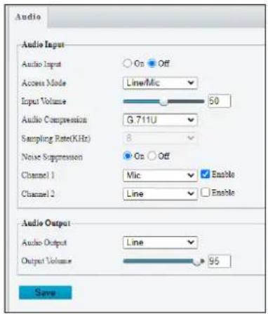
text_image
Audio Audio Input Audio Input Access Mode Line/Mic Input Volume 50 Audio Compression G.711U Sampling Rate(KHz) 8 Noise Suppression On Off Channel 1 Mic Enable Channel 2 Line Enable Audio Output Audio Output Line Output Volume 95 Save
text_image
Audio File Alama Audio File Browse... Import Note: PCM file only. File size must be lost than 100K. No. Audio Delete 1 You_are_in_the_slart_area!_Please_leave! 2 You_are_in_the_danger_area!_Do_not_approach! 3 Please_be_aware!_you_are_in_the_monitored_area! 4 No_packing!_Please_leave! 5 Important_place!_Please_leave! 6 Private_area!_Do_not_enter! 7 Danger!.Deep_water! 8 Danger!.Do_not_climb! 9 Welcome! 10 Warning! SaveFigure 3-17
■ Audio Input: Select On to enable audio input.
■ Input Volume: Set the audio signal amplification for sampling. The greater the volume, the greater amplification.
■ Audio Compression: Select an audio codec.
■ Noise Suppression: Select On to reduce the noise of the audio.
Channel 1 / 2: Click Enable to enable audio in through the camera's built-in microphone and/or Audio In wire(s) depending on the model.
■ Audio Output: Select the source of audio output.
■ Output Volume: Set the volume for audio output.
■ Alarm Audio File: For GV-TBL8804 only, select Browse to locate a custom PCM audio file (max. 100KB), and click Import.
Note: For GV-TDR2700 / 4700, connection(s) to any software/application must be reestablished when its audio input channel has been alternated for the change to take effect.
3.3.4 ROI
When Region of Interest (ROI) is enabled, the system ensures image quality for ROI first if the bit rate is insufficient.

text_image
ROI Area Area1Figure 3-18
- Click to enable and add ROI.
- Click and drag on the image to specify an area.
- To add additional ROI areas, repeat steps 1 and 2.
- To delete an ROI area, click .
Note: Up to two ROI areas can be specified for GV-ABL2703 series / 4703, GV-ADR2702 / 4702, GV-TBL2703 series / 4703 and GV-TDR2702 series / 4702 series, four for GV-ABL4711, GV-EBD4701 / 4712, GV-TBL4711, GV-TDR4703 series, GV-TFD4700, and GV-TVD4711, and eight for all other models.
3.3.5 Media Stream
Media Stream
By configuring media stream, you can set the camera to transmit code streams by UDP or TCP protocol to a specified IP address and port number. The settings can be saved and take effect after the camera is rebooted.

text_image
Media Stream RTSP Multicast Address Stream Profile Protocol Destination IP Destination Port Persistent Status + Add Media Stream Stream Profile Main Stream Destination IP Destination Port Protocol TS/UDP Persistent Enable Disable OK CancelFigure 3-19
- Click + and select a stream from the Stream Profile drop-down list.
- Type the Destination IP and Port number of the unicast or multicast group for the decoding device that receives video streams from the camera.
- Select a Protocol type for the media stream.
- If you want the device to automatically establish the media stream that has been previously configured after the restart, Enable Persistent.
- To delete a stream, click
- Click OK to complete the settings.
RTSP Multicast Address
After an RTSP multicast address is configured, the third-party player can request for the RTSP multicast media stream from the camera through RTSP protocol.
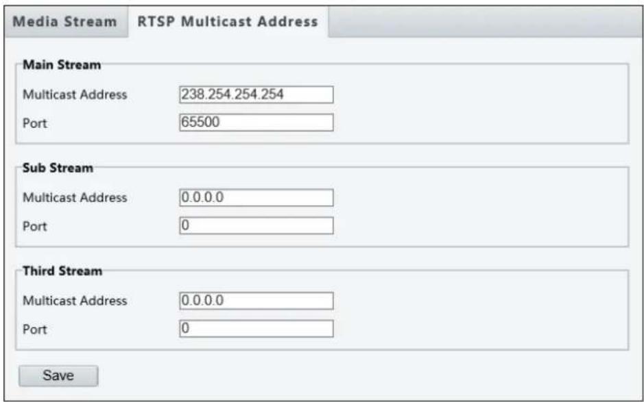
text_image
Media Stream RTSP Multicast Address Main Stream Multicast Address 238.254.254.254 Port 65500 Sub Stream Multicast Address 0.0.0.0 Port 0 Third Stream Multicast Address 0.0.0.0 Port 0 SaveFigure 3-20
- Type the Multicast Address (224.0.1.0 to 239.255.255.255) and Port number (0 to 65535).
- Click Save.
For RTSP Multicast command, see Appendix A.
3.4 PTZ
This section allows you to configure basic PTZ settings, home position, remote control, orientation and more on the PTZ camera. Note this is only applicable to GV-PTZ5810-IR.
3.4.1 Basic Settings
Basic settings allows you to configure basic PTZ settings related to the camera's position and PTZ control timeout.
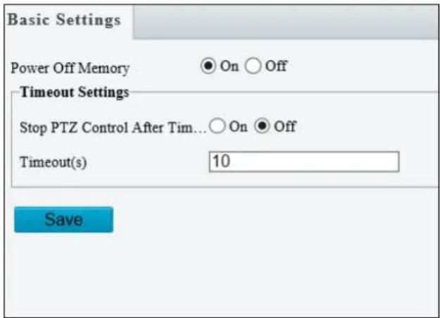
text_image
Basic Settings Power Off Memory ● On ○ Off Timeout Settings Stop PTZ Control After Tim... ○ On ● Off Timeout(s) 10 SaveFigure 3-21
[Power Off Memory] Select On to enable this function. When restarted, the camera returns to the position before it's powered off.
[Timeout Settings] Select On and set the timeout duration. PTZ control is disabled after the set timeout duration.
3.4.2 Home Position
The PTZ camera will return to home position if no operation is made within a specified period. Home Position allows you to select the desired preset as the home position and set the time.

text_image
Home Position Home Position On Off Mode Patrol ID [None] Idle State(s) 60 SaveFigure 3-22
3.4.3 Limit
Users can set PTZ limitations to prevent the camera from hitting obstacles such as walls.

text_image
Limit Start PTZ Limit [None] SaveFigure 3-23
- Click Start PTZ Limit to enable the function.
- Adjust the view in such a way that it reaches the PTZ limit you want to set.
- Click ✗ to set the position relative to the current dome view as a limit. For example, click the ✗ at the top to set the upper limit.
- Repeat Step 2 & 3 to set all limits as needed and click Save.
3.4.4 Remote Control
You can connect a third-party PTZ remote control program to your GV-IR IP Mini PTZ
Camera once this function is enabled.

text_image
Remote Control Remote Control On Off Listener Port 10008 Address Code 1 SaveFigure 3-24
- Specify the Listener Port to which the third-party PTZ remote control program connects.
- Assign an individual Address Code (between 0 \~ 255) to each PTZ remote control program
- Click Save.
Note: For this function, your router needs to support port forwarding.
3.4.5 Patrol
You can set the camera to take a snapshot and upload the image to the FTP server when the camera goes to the preset during the patrol route.
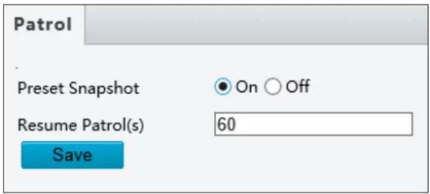
text_image
Patrol Preset Snapshot On Off Resume Patrol(s) 60 SaveFigure 3-25
- Enable Preset Snapshot.
- Type the Resume Patrol(s) interval in seconds to upload snapshots.
- Click Save.
Note: For this function, make sure to configure the settings in 3.8.2 FTP first.
3.4.6 Orientation
You can manually set a north direction or home position for the camera.

text_image
GeoVision Live View Playback Photo Setup Common Network Video & Audio PTZ Basic Settings Home Position Limit Remote Control Patrol Orientation Image Intelligent Events Storage Security System Orientation Orientation Home Position Manual Set as north Go to north Orient Call Clear [None]Figure 3-26
[Orientation]
■ Set as north: After the camera is positioned to a specific direction, the position will be set as the north direction.
■ Go to north: The camera will move to the specified north direction no matter which direction it points to.
[Home Position]
■ Orient: Click Orient to set a position as the home position.
■ Call: Click Call to move the camera to the specified home position no matter which direction it points to.
■ Clear: Click Clear to delete the home position.
3.5 Image
This section introduces the Image Settings, On-screen Display and Privacy Mask.
3.5.1 Image
This page allows you to adjust image settings such as brightness, exposure, IR illumination and white balance.
[Scene]
![Geovision 125-TBL8804 - [Scene] - 1](/content/2026/06/1217284/images/24a6ecfc62e35d8b8768d5a0e768091f0f5ab20f49329d311e75104ccb2945ba.jpg)
text_image
Scenes No. Current Scene Name Auto Switching Setup 1 ●Figure 3-27
■ Current: Indicates the scene that is being used.
■ Scene Name: When you select a scene, the corresponding image parameters are displayed. You can adjust the image settings according to actual needs.
■ Auto Switching: Indicates whether to add a scene to the auto-switching list.
■ Setup:
- Click to set a schedule for illumination.
- Click ✕ to set a scene as the default scene.
■ Enable Auto Switching: Allow the camera to switch to the scene automatically when the condition for switching to a non-default scene is met.
[Image Enhancement]
![Geovision 125-TBL8804 - [Scene] - 2](/content/2026/06/1217284/images/c5a47a58a7b9c07cd0962f923076870525cc47af5da27ba78b58ef401454aaae.jpg)
bar
| Image Enhancement | Value | | ----------------------- | ----- | | Brightness | 128 | | Saturation | 128 | | Contrast | 128 | | Sharpness | 128 | | 2D Noise Reduction | 128 | | 3D Noise Reduction | 128 | | Image Rotation | Normal |Figure 3-28
■ Brightness: Adjust the degree of brightness of the image.
■ Saturation: Adjust the amount of hue contained in a color.
■ Contrast: Set the degree of difference between the blackest pixel and the whitest pixel.
■ Sharpness: Adjust the sharpness of the image.
■ 2D / 3D Noise Reduction: Reduce the noise of the image.
■ Image Rotation: Change the rotation of the image by selecting Normal, Flip Vertical, Flip Horizontal, 180°, 90° Clockwise, or 90° Anti-clockwise.
Note: The image rotations of 90° Clockwise and 90° Anti-clockwise (Corridor format) are NOT supported by the following models: GV-ABL2701 series / 2703 series / 4703 / 4711, GV-ADR2701 / 2702 / 4702, GV-EBD4701 / 4712, GV-FER5702, GV-PTZ5810-IR, GV-TBL2703 / 2705 / 4700 / 4703 / 4711, GV-TDR2702 series / 4702 series / 4703 series, and GV-TFD4700, GV-TVD4700 / 4711.
[Exposure]
![Geovision 125-TBL8804 - [Scene] - 3](/content/2026/06/1217284/images/1666b99080c2ac141b71cad72093f7ebee5a3e0044ce24caab96e8ce4f5ab3d0.jpg)
text_image
Exposure Exposure Mode Outdoor Shutter(s) 1/100 Gain 0 Slow Shutter On Off Slowest Shutter 1/12 Compensation 0 Metering Control Center-Weighted Average Metering Day/Night Mode Automatic Day Night Day/Night Sensitivity Medium Day/Night Switching(s) 3 WDR Off WDR Level 5 Suppress WDR Stripes On OffFigure 3-29
■ Exposure Mode: Select the correct exposure mode to achieve the desired exposure effect. The default setting is Outdoor.
- Low Motion Blur: Improve image quality by reducing motion blur in low light conditions.
■ Shutter(s): The length of time that allows light to enter into the lens. You can set a shutter speed when Exposure Mode is set to Manual / Custom.
Note: If Slow Shutter is set to Off, the reciprocal of the shutter speed must be greater than the frame rate.
■ Gain: Control image signals so that the camera outputs standard video signals according to the light condition. You can set this parameter only when Exposure Mode is set to Manual / Custom.
■ Slow Shutter: Improve image brightness in low light conditions.
■ Slowest Shutter: Set the slowest shutter speed that the camera can use during exposure.
■ Compensation: Adjust the compensation value as required to achieve the desired effects. You can set this parameter only when Exposure Mode is not set to Manual / Custom.
■ Metering Control: Set the way the camera measures the intensity of light. You can only set this parameter when Exposure Mode is not set to Manual /Custom.
- Center-Weighted Average Metering: Measure light mainly in the central part of the images.
- Evaluative Metering (BLC): Measure light in the customized area of the images.
- Face Metering: Measure light where facial recognition is established.
- Spot Metering: Measure light spot(s) in the specified area of the images.
Day/Night Mode: Select Automatic for automatic switch between day mode and night mode depending on the amount of light detected. Select Night to produce high-quality black and white images using the existing light. Select Day to produce high-quality color images using the existing light. Select Input Boolean to trigger an output device and switch on night mode upon common alarm / AI event alarm (only applicable to GV-EBFC5800 / GV-TDR8802).
■ Day/Night Sensitivity: Set the light threshold for switching between day mode and night mode. The higher the sensitivity, the more easily the camera is to switch from day mode to night mode and vice versa.
■ Day/Night Switching(s): Set the length of time before the camera switches between day mode and night mode after the conditions for switching are met.
■ WDR: Enable WDR to distinguish the bright and dark areas in the same image.
■ WDR Level: After enabling the WDR function, you can improve the image by adjusting the WDR level.
■ Suppress WDR Stripes: Enable Suppress WDR Stripes to automatically adjust shutter frequency based on the frequency of light measured.
[Smart Illumination]
![Geovision 125-TBL8804 - [Smart Illumination] - 1](/content/2026/06/1217284/images/408a9a3263156c49894533a7385fc096cddd23cf45a7774342d2ed4bf5e5849b.jpg)
text_image
Smart Illumination Smart Illumination ● On ○ Off Illumination Mode Infrared Control Mode Global Mode Illumination Level 0Figure 3-30
■ Smart Illumination: Select On to adjust the IR illumination settings.
■ Illumination Mode:
- For regular models: Set to Infrared by default.
- For GV-BLFC5800 / EBFC5800: Set to White Light by default.
- For GV-TBL8804: Refer to the table below to configure the settings.
| Illumination Mode | Action | ||
| Daytime | Nighttime | ||
| With AI functions disabled | Infrared | Day Mode enabled | Night Mode and IR light enabled. |
| White Light | Day Mode enabled | Day Mode and White LED light enabled. | |
| With AI functions enabled | Infrared | Day Mode enabled. White LED light flashes for 10 seconds upon an alarm trigger. | Night Mode and IR light enabled. White LED light flashes for 10 seconds upon an alarm trigger. |
| White Light | Day Mode and White LED light enabled. | ||
| Dual Light | Night Mode and IR light enabled. Switches to Day Mode and White LED light flashes for 10 seconds upon an alarm trigger. | ||
Note:
- AI functions refer to the smart settings, including Cross Line, Intrusion, Object Removed, Object Left Behind, Defocus, Scene Change, Enter Area, Leave Area, Face Detection, People Counting, Crowd Density Monitoring, and Human Body Detection. See details in 3.6.1 Smart Settings.
- White Light refers to Warm Light LED for GV-BLFC5800 / GV-EBFC5800 / GV-TBL8804.
Control Mode:
■ Global Mode: Adjust IR illumination and exposure to achieve balanced image effects. Some areas might be overexposed if you select this option. This option is recommended if monitored range and image brightness are your first priority.
■ Overexposure Restrain: Adjust IR illumination and exposure to avoid regional overexposure. Some areas might be dark if you select this option. This option is recommended if clarity of the central part of the image and overexposure control are your first priority.
■ Manual / Custom Level: Allow you to manually control the intensity of IR illumination.
■ Illumination Level: When Control Model is set to Manual / Custom Level, you can set the intensity level of the IR light. The greater the value, the higher the intensity. 0 means that the IR light is turned off.
Near / Far Illumination Level: For GV-TBL8804 only, when Illumination Mode is set to Dual Light and Control Mode to Manual, you can set the intensity level of the IR light respectively for wide-angle scene (near illumination level) and telephoto view (far illumination level).
[White Balance]
![Geovision 125-TBL8804 - [White Balance] - 1](/content/2026/06/1217284/images/d9ef2c11798ee319143faf4939c78274f8e0d8926ffe7961027ab28ffcaf17a1.jpg)
text_image
White Balance White Balance Auto Red Offset 4 Blue Offset 14Figure 3-31
■ White Balance: Adjust the red or blue offset of the image.
- Auto / Auto 2: Adjust the red and blue offset automatically according to the light condition (the color tends to be blue). Select Auto 2 if the images remain unnaturally red or blue.
- Outdoor: It is recommended for outdoor scenes with a wide range of color temperature variation.
- Fine Tune: Allow you to adjust the red and blue offset manually.
- Sodium Lamp: Adjust the red and blue offset automatically according to the light condition (the color tends to be red).
- Locked: Lock the current color temperature settings without adjustment.
[Advanced]
![Geovision 125-TBL8804 - [Advanced] - 1](/content/2026/06/1217284/images/ecf08005f673e145887f613140f8eff3a527e34cc86b453a7125cc56e9ed6785.jpg)
text_image
Advanced Defog Off Defog Intensity 5 Dewarping Off Dewarping Level 5Figure 3-32
■ Defog: Select On to activate the slider for adjusting the defog intensity of the image.
■ Dewarping: Only for GV-ABL2703 series / 4703, GV-ADR2702 / 4702, GV-EBD8800 / 8813, GV-TBL2703 series / 4703 / 8804 / 8810, GV-TDR2702 series / 4702 series / 8805 and GV-TVD8810, select On to activate the slider for adjusting the Dewarping Level of the camera image.
3.5.2 OSD
On Screen Display (OSD) is the text displayed on the screen of video images and may include the date and time and other customized contents. Note GV-ABL2703 series / 4703 / 4711, GV-ADR2702 / 4702, GV-EBD2704 / 4701 / 4704 / 4712 / 4813, GV-TBL2703 series / 2705 / 4700 / 4703 / 4705 / 4711, GV-TDR2702 series / 2704 series / 4702 series / 4703 series / 4704 series, GV-TFD4700, and GV-TVD4700 / 4711 only support up to 4 OSD.
3.4.2.1 For all models except GV-EBD2702
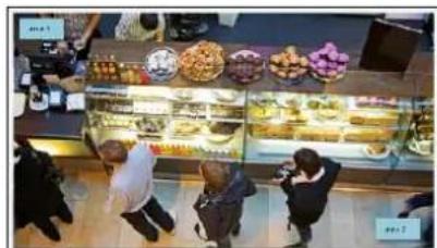
natural_image
Interior view of a food stall with customers browsing display cases (no visible text or signage)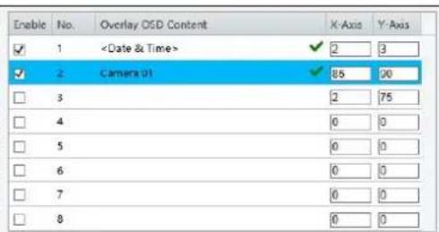
text_image
Enable No. Overlay OSD Content X-Axis Y-Axis ✓ 1
text_image
Display Style Effect Background Font Size Medium Font Color #0000-1 Min. Margin Single Date Format dd/MM/yyyy dd=Day; dddd=Day of the week; M=Month; y=Year Time Format HH mm:98 h/H=12/24 Hour; t=A.M. or P.M.; mm=Minute; ss=SecondFigure 3-33
- Enable a No. to select an area #, and click Overlay OSD Content to select the content to display on the screen.
- Adjust the position of the Area 1/2/3 boxes either by dragging them directly on the live view or by specifying the coordinates under X-Axis / Y-Axis column.
- Under Display Style, customize the text style and date/time format and use Min. Margin, to adjust the minimum margin between the OSD and the image's border.
3.4.2.2 For GV-EBD2702
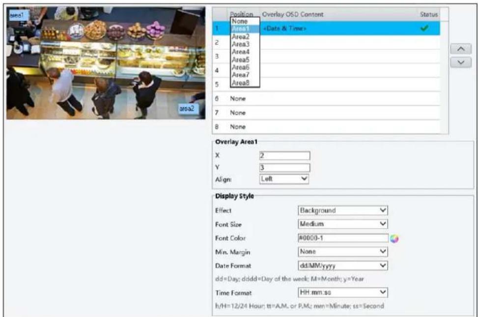
text_image
area1 Position Overlay OSD Content Status None Area1Figure 3-34
- Click Overlay OSD Content to select the content or type a self-defined text to be displayed on the screen.
- Click Position and select from Areas 1 to 8 to specify the position of the OSD on the image. If more than one OSD are specified to one Area #, they are displayed at the same position in numerical order, as accorded to the number column.
- Click the arrow buttons ↗ or ▼ to adjust the order of the OSD displayed.
- Adjust the position of the Area 1/2/3 boxes either by dragging them directly on the live view or by specifying the coordinates under X-Axis / Y-Axis column.
- Under Display Style, customize the text style and date/time format and use Min. Margin, to adjust the minimum margin between the OSD and the image's border.
After you have set the position and OSD content, the symbol appears in the Status column, which means that the OSD is set successfully.
Note: You can also configure OSD under Common for GV-ABD1300, ABL2701, ADR1300, BLFC5800, EBD4700 / 8711, EBFC5800, TBL2705 / 4700 / 4701 / 8804, TDR2700 / 2704 / 8805, and TFD4700 / 4800.
3.5.3 Privacy Mask
On certain occasions, you may need to set a mask area to block out parts of the camera image to protect privacy, for example, the keyboard of an ATM machine. When PTZ changes its position or zooms, the Privacy Mask will be adjusted accordingly to protect the area all along.

text_image
Add Delete Note: Up to 4 mask areas are allowed for each scene No. Name Max. Zoom Operation 1 Mask1 1.00 Set As Max. Preset 2 Mask2 1.00Figure 3-35
- Click to place a privacy mask on the live view.
- Drag the Mask box to the intended position and adjust the size of the box. Alternatively, you can also use the mouse to draw a box on the area you want to mask.
- Repeat steps 1 and 2 to add more masks.
- To delete a mask, select the desired mask and click . Delete
Note:
- Up to four mask areas can be defined for GV-ABL2703 series / 4703 / 4711, GV-ADR2702 / 4702, GV-BLFC5800, GV-EBD2704 / 4701 / 4704 / 4712 / 4813 / 8800 / 8813, GV-EBFC5800, GV-TBL2703 series / 2705 / 4700 / 4703 / 4705 / 4711 / 4810 / 8710 / 8804 / 8810, GV-TDR2702 series / 2704 series / 4702 series / 4703 series / 4704 series / 4803 series / 8805, GV-TFD4700 / 4800, GV-TVD4700 / 4711 / 4810 / 8810, and GV-FER5702, twenty-four mask areas for GV-PTZ5810-IR, and up to eight mask areas for all other models.
- Max. Zoom and Operation are only applicable to GV-PTZ5810-IR.
3.6 Intelligent
Under Intelligent, users can set the camera to detect for a number of video-analytic events, which can be used to send FTP and/or e-mail alerts, based on the parameters set. Note this function is NOT supported by GV-ABL2701 series / 2703 series / 4701 series / 4703, GV-ADR2701 / 2702 / 4701 / 4702, GV-TBL2703 series / 4703, GV-TDR2702 / 4702, and GV-FER5702.
3.6.1 Smart Settings
Smart Settings allow alerts to be sent to FTP and/or designated e-mail address(es) upon Cross Line, Intrusion, Object Removed, Object Left Behind, Defocus, Scene Change, Enter Area, Leave Area, Face Detection, People Counting, Crowd Density Monitoring and/or Human Body Detection events.
Note:
- In order for event alerts to work, you also need to configure the necessary settings of FTP, e-mail server and snapshots, see 3.8.2 FTP, 3.2.5 E-mail and 3.3.2 Snapshot, respectively.
- For certain models, to display the detection lines and/or areas on the live view, you need to enable Untriggered Target as mentioned in 3.1.2 Local Parameters.
- GV-ABL4711, GV-EBD4701 / 4712, GV-TBL4700 / 4711, GV-TDR4703 series, GV-TFD4700, and GV-TVD4700 / 4711 only support two smart settings: Intrusion and Human Body Detection.
- GV-EBD2704 / 4704, GV-TBL2705 / 4705, and GV-TDR2704 series / 4704 series only support two smart settings: Cross Line and Intrusion.
- GV-BLFC5800, GV-EBD4813 / 8800 / 8813, GV-EBFC5800, GV-TBL4810 / 8804 / 8810, GV-TDR4803 / 8805, GV-TFD4800, GV-TVD4810 / 8810, and GV-PTZ5810-IR support Cross Line, Intrusion, Enter Area, Leave Area, Face Detection, People Counting, and Crowd Density Monitoring.
- Smart Settings will not work if Image Rotation is set to 90° Clockwise or 90° Anti-clockwise under the Image Enhancement settings in 3.5.1 Image.

text_image
Smart Perimeter Protection Cross Line Enter Area Leave Area Intrusion Exception Detection & Statistics Object Removed Object Left Behind Defocus Scene Change Object Detection Face People Counting People CountingFigure 3-36
3.6.1.1 Cross Line
Cross line detection generates an alarm when an object moves past the detection threshold in the direction you defined. Up to 4 detection lines can be added. Note that when adding multiple detection lines, make sure they do NOT intersect as it may affect the detection results. Select the checkbox next to Cross Line to enable and click 🔗 to configure.

For GV-BLFC5800, GV-EBD4813 / 8800 / 8813, GV-EBFC5800, GV-PTZ5810-IR, GV-TBL4810 / 8804 / 8810, GV-TDR4803 / 8805, GV-TFD4800, and GV-TVD4810 / 8810
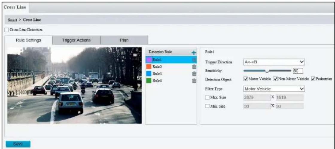
text_image
Cross Line Smart > Cross Line Cross Line Detection Rule Settings Trigger Actions Plan Detection Rule Rule1 Rule2 Rule3 Rule4 Rule1 Trigger Direction A<->B Sensitivity 50 Detection Object ✓ Motor Vehicle ✓ Non Motor Vehicle ✓ Pedestrian Filter Type Motor Vehicle Max. Size 2879 X 1619 Min. Size 30 X 30 SaveFigure 3-37
- Click + to add a detection line. Repeat to add another detection line (maximum of 4).
- Drag the ends of the detection line to the intended position to mark the detection boundary.
- Select the Trigger Direction, which defines the direction to trigger an alarm. For example, if you choose A -> B, people moving from direction A to B will trigger an alarm.
- For Sensitivity, drag the slider to adjust the detection sensitivity.
- For Detection Object, select the type of object you want to take a snapshot of.
- For Filter Type, select the type of object you want to define and its minimum or maximum size for detection. Once selected, click Max. Size and/or Min. Size, drag the nodes of the size area to adjust and the system will detect objects within that size range. Repeat this step to define the size range for another type of object.
- For Trigger Actions and Plan, follow Step 6 \~ 7 below.
Note: Motor Vehicle includes cars, trucks, and buses. Non-Motor Vehicle includes bicycles and motorcycles.
For other models NOT equipped with AI functions
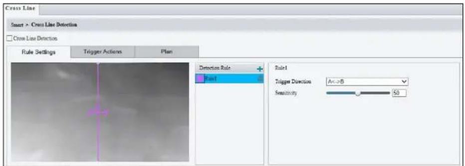
text_image
Cross Line Smart > Cross Line Detection Cross Line Detection Rule Settings Trigger Actions Plan Detection Rule Rate1 Rule1 Trigger Direction A<>B Sensitivity 50Figure 3-38
- Based on your installation environment, select the Detection Scene between outdoor and indoor (see Detection Parameters in 3.6.2 Advanced Settings). By default, Outdoor is selected.
- Once enabled, select Rule Settings > click + to add a detection line. Repeat to add another detection line.
- Drag the ends of the detection line to the intended position to mark the detection boundary.
- Select the Trigger Direction, which will define the direction to trigger an alarm. For example, if you choose A -> B, people moving from direction A to B will trigger an alarm.
- Move the slider to adjust the detection Sensitivity.
- Set up Trigger Actions:
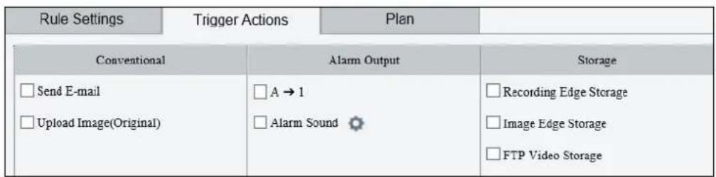
text_image
Rule Settings Trigger Actions Plan Conventional Alarm Output Storage Send E-mail A → 1 Recording Edge Storage Upload Image(Original) Alarm Sound Image Edge Storage FTP Video StorageFigure 3-39
A. Select Upload to FTP / Send E-mail / Upload Image (Original) under Trigger Actions to automatically upload snapshots to the specified FTP server and/or send snapshots to the specified e-mail address upon the video analytic events.
B. Select A -> 1 / Alarm Sound to trigger an output device upon cross line detection. Depending on your model, select A -> 1 or Alarm Sound to trigger an output device upon people / vehicle / non-motor vehicle detection.
C. Optionally click ✿ next to Alarm Sound to set the desired Day, Start Time, End Time, Alarm Audio, and Number of Repeat Times. You can set up to four periods for each time, and the time periods cannot overlap.
D. Select Recording Edge Storage, Image Edge Storage, or FTP Video Storage. Snapshots captured or videos recorded will automatically be stored in the selected storages.
- Optionally select Enable Plan under Plan to set the start and end times during which the video analytic monitoring is enabled. You can directly drag the mouse to draw a plan or click Edit to edit time periods in the table. You can set up to four periods for each day, and the time periods cannot overlap. The camera reports alarms during the specified period only.

text_image
Rule Settings Trigger Actions Plan Enable Fla Aimed Unarmed Edit Mon Tue Wed Thu Fri Sat Sun
text_image
Edit Mon Tue Wed Thu Fri Sat Sun No. Start Time End Time 1 00 00 00 23:50:50 2 3 4 Copy To Select All ✓ Mon Tue Wed Thu Fri Sat Sun Copy OK CancelFigure 3-40
Note:
- Certain models may only support uploading snapshots to an FTP server and output trigger for Trigger Actions.
- Alarm Sound is only applicable to GV-PTZ5810-IR / GV-TBL8804 and Alarm Light is only applicable to GV-TBL8804. See details in 3.3.3 Audio for Alarm Sound and 3.5.1 Image (Smart Illumination) for Alarm Light.
Also see Appendix J. Installation Guidelines for Perimeter Protection.
3.6.1.2 Intrusion
With Intrusion Detection, an alarm is generated when an object enters the boundaries of the detection area. Up to 4 detection areas can be added. Note that it is recommended NOT to overlap the detection areas when adding multiple detection areas. Select the checkbox next to Intrusion to enable and click to configure.
For GV-BLFC5800, GV-EBD4813 / 8800 / 8813, GV-EBFC5800, GV-PTZ5810-IR, GV-TBL4810 / 8804 / 8810, GV-TDR4803 / 8805, GV-TFD4800, and GV-TVD4810 / 8810
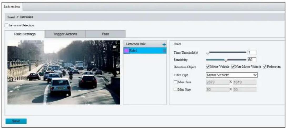
text_image
Intrusion Smart > Intrusion Intrusion Detection Rule Settings Trigger Actions Plan Detection Rule Rule1 Time Threshold(s) 1 Sensitivity 50 Detection Object ✓ Motor Vehicle ✓ Non-Motor Vehicle ✓ Pedestrian Filter Type Motor Vehicle Max. Size 2879 X 1619 Min. Size 30 X 30 SaveFigure 3-41
- Click to mark the live view with a detection area. Repeat this step to add another detection area (maximum of 4).
- Drag the nodes of the detection area to mark the boundary for detection.
- You can use the following functions to reduce false alarm.
■ Time Threshold: The minimum period of time for an object to stay within the detection area before an alarm is triggered.
■ Sensitivity: Move the slider to adjust the detection sensitivity.
- For Detection Object, select the type of object you want to take a snapshot of.
- For Filter Type, select the type of object you want to define and its minimum or maximum size for detection. Once selected, click Max. Size and/or Min. Size, drag the nodes of the size area to adjust and the system will detect objects within that size range. Repeat this step to define the size range for another type of object.
- For Trigger Actions and Plan, follow Step 6 \~7 at the bottom of 3.6.1.1 Cross Line.
Note:
- Certain models may only support uploading snapshots to an FTP server and output trigger for Trigger Actions.
- Motor Vehicle includes cars, trucks, and buses. Non-Motor Vehicle includes bicycles and motorcycles.
- Alarm Sound is only applicable to GV-PTZ5810-IR / GV-TBL8804 and Alarm Light is only applicable to GV-TBL8804. See details in 3.3.3 Audio for Alarm Sound and 3.5.1 Image (Smart Illumination) for Alarm Light.
For other models NOT equipped with AI functions
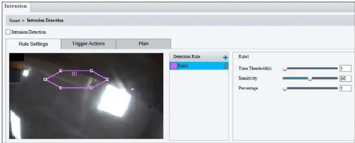
text_image
Intrusion Smart > Intrusion Detection Intrusion Detection Rule Settings Trigger Actions Plan Detection Rule Rule1 Rule1 Time Threshold(s) 1 Sensitivity 50 Percentage 1Figure 3-42
- Based on your installation environment, select the Detection Scene between outdoor and indoor (see Detection Parameters in 3.6.2 Advanced Settings). By default, Outdoor is selected.
- Once enabled, click to mark the live view with a detection area. Repeat this step to add another detection area.
- Drag the nodes of the detection area to mark the boundary for detection.
- You can use the following functions to reduce false alarm.
■ Time Threshold: The minimum period of time for an object to stay within the detection area before an alarm is triggered.
■ Sensitivity: Move the slider to adjust the detection sensitivity.
■ Percentage: Type the minimum size of the object compared to the detection area for the object to be detected.
- For Trigger Actions and Plan, follow Step 6 \~ 7 at the bottom of 3.6.1.1 Cross Line.
Note: Under Trigger Actions:
- Alarm Output and Storage are not supported by GV-TBL4700 and GV-TVD4700.
- Alarm Output is not supported by GV-EBD2704 / 4701 / 4704 / 4712, GV-EBFC5800, GV-TBL2705 / 4705, and GV-TDR2704 series / 4704 series.
Also see Appendix J. Installation Guidelines for Perimeter Protection.
3.6.1.3 Object Removed
Object Removed can generate an alarm when an object is removed from the specified area. Up to 4 detection areas can be added. Note that it is recommended NOT to overlap the detection areas when adding multiple detection areas. Select the checkbox next to Object Removed to enable and click to configure.

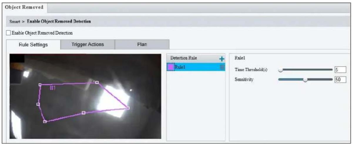
text_image
Object Removed Smart > Enable Object Removed Detection Enable Object Removed Detection Rule Settings Trigger Actions Plan Detection Rule Rule1 Rule1 Time Threshold(s) 5 Sensitivity 50Figure 3-43
- Once enabled, click to mark the live view with a detection area. Repeat this step to add another detection area.
- Drag the nodes of the detection area to mark the boundary for detection.
- You can use the following functions to reduce false alarm.
■ Time Threshold: The minimum period for an object to be absent from the detection area before an alarm is triggered.
■ Sensitivity: Move the slider to adjust the detection.
- For Trigger Actions and Plan, follow Step 6 \~ 7 at the bottom of 3.6.1.1 Cross Line.
3.6.1.4 Object Left Behind
With Object Left Behind, an alarm can be generated when an object which remained in the detection area for the specified period of time, leaves the specified region. Up to 4 detection areas can be added. Note that it is recommended NOT to overlap the detection areas when adding multiple detection areas. Select the checkbox next to Object Left Behind to enable and click to configure.


text_image
Object Left Behind Smart > Enable Object Left Behind Detection Enable Object Left Behind Detection Rule Settings Trigger Actions Plan Detection Rule Rule1 Rule1 Time Threshold(s) 5 Sensitivity 50Figure 3-44
- Once enabled, click + to mark the live view with a detection area. Repeat this step to add another detection area.
- Drag the nodes of the detection area to mark the boundary for detection.
- You can use the following functions to reduce false alarm.
■ Time Threshold: The minimum period of time for an object to stay within the detection area for an alarm to trigger.
■ Sensitivity: Move the slider to adjust the detection sensitivity.
- For Trigger Actions and Plan, follow Step 6 \~ 7 at the bottom of 3.6.1.1 Cross Line.
3.6.1.5 Defocus
Defocus generates an alarm to be sent through e-mail whenever the camera's image is out of focus. Select the checkbox next to Defocus to enable and click 🔗 to configure.
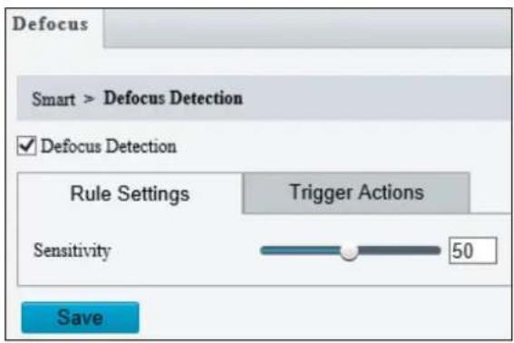
text_image
Defocus Smart > Defocus Detection ✓ Defocus Detection Rule Settings Trigger Actions Sensitivity 50 SaveFigure 3-45
Once enabled, drag the slider to adjust the detection Sensitivity. For Trigger Actions, follow Step 6 at the bottom of 3.6.1.1 Cross Line.
3.6.1.6 Scene Change
Scene Change is able to generate an alarm whenever there is a drastic scene change to the image of the camera. Select the checkbox next to Scene Change to enable and click 🔗 to configure.
text_image
Scene Change
text_image
Scene Change Smart > Scene Change Detection ✓ Scene Change Detection Rule Settings Trigger Actions Plan Sensitivity 50 SaveFigure 3-46
Once enabled, drag the slider to adjust the detection Sensitivity. For Trigger Actions and Plans, follow Step 6 \~ 7 at the bottom of 3.6.1.1 Cross Line.
3.6.1.7 Face Detection
The Face function can detect for and capture face(s) in a specified area and send to an FTP server. Select the checkbox next to Face to enable and click 🔗 to configure.

text_image
FaceFor other models NOT equipped with AI functions
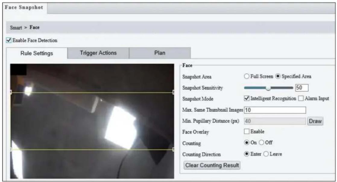
text_image
Face Snapshot Smart > Face Enable Face Detection Rule Settings Trigger Actions Plan Face Snapshot Area Full Screen Specified Area Snapshot Sensitivity 50 Snapshot Mode Intelligent Recognition Alarm Input Max. Same Thumbnail Images 10 Min. Pupillary Distance (px) 40 Draw Face Overlay Enable Counting On Off Counting Direction Enter Leave Clear Counting ResultFigure 3-47
- Once enabled, define the detection area, either by drawing a desired area on the image or select Full Screen next to Specified Area to set the entire image as detection area.
- Configure the following functions as needed:
■ Snapshot Sensitivity: Drag the slider to adjust the detection sensitivity. By default, the value is set to 50. When the sensitivity is increased, the detection rate increases but so does the false detection rate, and vice versa.
■ Snapshot Mode: Select Intelligent Recognition to set the maximum of repeated face snapshots (1\~30) for Max. Same Thumbnail Image.
■ Min. Pupillary Distance (px): Click Draw and draw in the live view window. Set according to camera resolutions. The min. pupillary distance should be 1/2 of face pixel.
■ Face Overlay: Enable to include the camera's text overlay on the snapshot(s) captured.
- Under Trigger Actions, select Upload Image (Original) to upload a snapshot of the entire image and a snapshot of the face detected upon face detection. Select Upload Image (Target) to upload only the snapshot of the face detected.
- For Plan, follow Step 7 at the bottom of 3.6.1.1 Cross Line.
Note: The Counting and Counting Direction features are currently nonfunctional.
For GV-BLFC5800, GV-EBD4813 / 8800 / 8813, GV-EBFC5800, GV-PTZ5810-IR, GV-TBL4810 / 8804 / 8810, GV-TDR4803 / 8805, GV-TFD4800, and GV-TVD4810 / 8810

text_image
Face Detection Smart > Face Detection Enable Face Detection Rule Settings Masked Area Trigger Actions Plan Face Detection Snapshot Area Full Screen Specified Area Snapshot Sensitivity 50 Snapshot Mode Intelligent Recognition Alarm Input Min. Pupillary Distance (px) 60 Draw Counting On Off Reset Counter at 00:00:00 Clear Counting Result Face Selection Selection Mode Effect Priority Number of Selected Photos 1 Filter by Angle On OffFigure 3-48
- Once enabled, define the detection area, either by selecting Specified Area and drawing a desired area on the image, or select Full Screen to set the entire image as detection area.
- Configure the following functions as needed:
[Face Detection]
■ Snapshot Sensitivity: Drag the slider to adjust the detection sensitivity.
■ Snapshot Mode: Select Intelligent Recognition for the camera to detect and take snapshots of the object automatically.
■ Min. Pupillary Distance (px): Click Draw and draw in the live view window.
■ Counting: To count the number of people entering / exiting in the detection area, enable this function. To display the counting results in the live view window, select People Counting in OSD settings. Refer to 3.5.2 OSD for details.
[Face Selection]
■ Selection Mode: Select Effect Priority for the best image quality of the captured snapshots, Speed Priority for optimal snapshots from the moment of detection until the specified timeout is up, and Periodic Selection for a snapshot captured in every selection period. For example, if Periodic Selection is set to 500 millisecond (ms), the camera selects a face snapshot every 500 ms.)
■ Number of Selected Photos: Set 1 \~ 3 selected photos for different selection modes.
■ Filter by Angle: Enable this function to set the desired face angle for detection.
-
Under Trigger Actions, select Upload Image (Original) to upload a snapshot of the entire image and a snapshot of the face detected upon face detection. Select Upload Image (Target) to upload only the snapshot of the face detected.
-
For Plan, follow Step 7 at the bottom of 3.6.1.1 Cross Line.
Local Snapshot
Click the Start Capture button (see figure below) on the Live View page to start taking local snapshots.

natural_image
Toolbar with application icons including photo, image editing, 3D cube, and control buttons (no readable text or symbols)When enabled, captured faces and people will display in real time on the right side of the Live View page.
Note: If green detection boxes are displayed but local snapshots are not, re-install the plugin, disable the firewall on your computer, and disable the protected mode for all the zones in your IE (Internet options > Security).
Also see Appendix M. Installation Guidelines for Face Detection, and Appendix O. Installation Guidelines for Face Detection (Non-AI).
3.6.1.8 People Counting
The People Counting function can count the number of person(s) entering and leaving the vicinity, which is useful at an entrance/exit setting. Select the checkbox next to People Counting to enable and click to configure.

For other models NOT equipped with AI functions

text_image
People Counting Smart > People Counting Enable People Counting Rule Settings Plan Counting Type Total Detection Mode Indoor Reset Counter at 00:00:00 Report Interval(s) 60 Sensitivity 50 Draw Detection Area Draw Entrance Direction Filter by Object Size (Width X Height)(px) Max. Size 219 X 219 Min. Size 120 X 120 Tip: Please set the detection area between the two red lines to achieve the best detection effect. Clear Counting ResultFigure 3-49
- Once enabled, draw a detection area and entrance direction on the image by clicking Draw Detection Area and Draw Entrance Direction, respectively.
- Select the desired Counting Type, from Total, People Entered or People Left.
- Select a Detection Mode, between Indoor and Outdoor, depending on your environment.
- Under Filter by Object Size, set the Max. and Min. Size of the objects to be counted.
- Select Reset Counter at to set a time within a day when to reset the counter.
- Adjust the detection sensitivity by dragging the Sensitivity slider.
- For Plan, follow Step 7 at the bottom of 3.6.1.1 Cross Line.
For GV-BLFC5800, GV-EBD4813 / 8800 / 8813, GV-EBFC5800, GV-PTZ5810-IR, GV-TBL4810 / 8804 / 8810, GV-TDR4803 / 8805, GV-TFD4800, and GV-TVD4810 / 8810

text_image
People Flow Counting Smart > People Flow Counting Enable People Flow Counting Rule Settings Trigger Actions Plan Data Report Interval(s) 60 Reset Counter at 00:00:00 Clear Enter B->A Counting Type Total People Present Alarm Minor Alarm ≥60 Major Alarm ≥120 Critical Alarm ≥180 [None]Figure 3-50
- Once enabled, draw a detection line and define the entrance direction. Select the entrance direction from the Enter drop-down list.
- Select the desired Counting Type, from Total, People Entered or People Exited. When any of the People Present Alarms is enabled, this function will not be available.
- Under People Present Alarm, set the Minor Alarm, Major Alarm, or Critical Alarm. When the number of people present reaches a set threshold, an alarm will be triggered.
- Select Reset Counter at to set a time within a day when to reset the counter.
- For Trigger Actions, select 🔍 to edit the desired trigger actions under each alarm. See Step 6 at the bottom of 3.6.1.1 Cross Line for details.
- For Plan, follow Step 7 at the bottom of 3.6.1.1 Cross Line.
Also see Appendix K. Installation Guidelines for People Flow Counting, and Appendix P. Installation Guidelines for People Counting (Non-AI).
3.6.1.9 Human Body Detection
Human Body Detection is used to generate an alarm whenever a human figure appears in the specified area. Note this function is only applicable to GV-ABL4711, GV-EBD4701 / 4712, GV-TBL4700 / 4711, GV-TDR4703 series, GV-TFD4700, and GV-TVD4700 / 4711.

text_image
Human Body Detection Enable Human Body Detection Snapshot Area Level 1 Arrow Reversibility Low High Arrow Parameters Suppress Alarm:0 45 Clear Alarm:0 5 Trigger Action: Recording Storage Upload to FTP Trigger Email Image Filterage Enable Flex Armed Unnamed Edit Min Top Next Down Up Exit Run SaveFigure 3-51
- In the Snapshot Area, click + to add a new detection area.
- Click and drag the detection area to a desired location.
- Adjust the detection sensitivity by dragging the Sensitivity slider.
- Set up Alarm Parameters.
■ Suppress alarm: After a detection is triggered, the detection will not be reported within the set time.
■ Clear alarm: After a detection is triggered,
- If the detection is not triggered within the set time, the detection will be cleared and the detection can be reported again.
-
If the detection is triggered within the set time, the detection will not be cleared until the suppress alarm time expires. Then the detection can be reported again.
-
Set up Trigger Actions.
■ Upload to FTP and Trigger E-mail: Automatically upload snapshots captured to the specified FTP server and/or send snapshots to the specified e-mail address.
■ Recording Storage and Image Storage: Automatically save videos and/or snapshots captured to the selected storage(s).
- For Enable Plan, follow Step 7 at the bottom of 3.6.1.1 Cross Line.
3.6.1.10 Enter Area / Leave Area
With Enter Area / Leave Area, an alarm is generated when a person or vehicle enters / leaves the boundaries of the detection area. Note this function is only applicable to GV-BLFC5800, GV-EBD4813 / 8800 / 8813, GV-EBFC5800, GV-PTZ5810-IR, GV-TBL4810 / 8804 / 8810, GV-TDR4803 / 8805, GV-TFD4800, and GV-TVD4810 / 8810. It is also NOT recommended to overlap the detection areas when adding multiple detection areas.
Select the checkbox next to Enter Area or Leave Area to enable and click 🔗 to configure.

text_image
Enter Area Leave AreaHere we use Enter Area as an example.
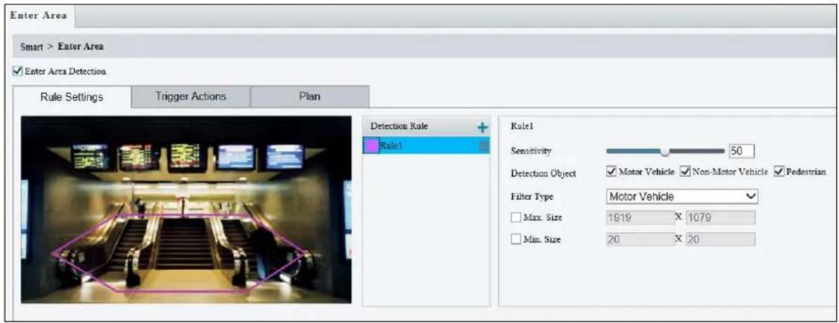
text_image
Enter Area Smart > Enter Area ✓ Enter Area Detection Rule Settings Trigger Actions Plan Detection Rule Rule1 Rule1 Sensitivity 50 Detection Object ✓ Motor Vehicle ✓ Non-Motor Vehicle ✓ Pedestrian Filter Type Motor Vehicle Max. Size 1919 X 1079 Min. Size 20 X 20Figure 3-52
- Click + to mark the live view with a detection area. Repeat this step to add another detection area (maximum of 4).
- Drag the nodes of the detection area to mark the boundary for detection.
- For Sensitivity, drag the slider to adjust the detection sensitivity.
- For Detection Object, select the type of object to detect when it enters / leaves area.
- For Filter Type, select the type of object you want to define and its minimum or maximum size for detection. Once selected, click Max. Size and/or Min. Size, drag the nodes of the size area to adjust and the system will detect objects within that size range. Repeat this step to define the size range for another type of object.
- Under Trigger Actions, select Upload Image (Original) to automatically upload snapshots to the specified FTP server. Depending on your model, select A -> 1, Alarm Sound, or Alarm Light to trigger an output device upon people / vehicle / non-motor vehicle detection.
- Optionally click ✪ next to Alarm Sound to set the desired Day, Start Time, End Time, Alarm Audio, and Number of Repeat Times. You can set up to four periods for each time, and the time periods cannot overlap.
- For Plan, follow Step 7 at the bottom of 3.6.1.1 Cross Line.
Note:
- Certain models may only support uploading snapshots to an FTP server and output trigger for Trigger Actions.
- Motor Vehicle includes cars, trucks, and buses. Non-Motor Vehicle includes bicycles and motorcycles.
- Alarm Sound is only applicable to GV-PTZ5810-IR / GV-TBL8804 and Alarm Light is only applicable to GV-TBL8804. See details in 3.3.3 Audio for Alarm Sound and 3.5.1 Image (Smart Illumination) for Alarm Light.
Also see Appendix J. Installation Guidelines for Perimeter Protection.
3.6.1.11 Crowd Density Monitoring
With Crowd Density Monitoring, an alarm is triggered when the number of people in a specified area exceeds the defined alarm threshold. Note this function is only applicable to GV-EBD4813 / 8800 / 8813, GV-BLFC5800, GV-EBFC5800, GV-PTZ5810-IR, GV-TBL4810 / 8804 / 8810, GV-TDR4803 / 8805, GV-TFD4800, and GV-TVD4810 / 8810.
Select the checkbox next to Crowd Density Monitoring to enable and click 🔗 to configure.
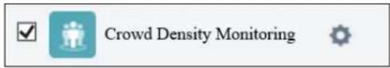
text_image
Crowd Density Monitoring
text_image
Crowd Density Monitoring Smart > Crowd Density Monitoring Enable Crowd Density Monitoring Rule Settings Trigger Actions Plan Report Interval(s) 60 Crowd Density Alarm Minor Alarm ≥20 Major Alarm ≥24 Critical Alarm ≥30Figure 3-53
- Once enabled, define the detection area on the live view.
- For Report Interval(s), set the time interval (in seconds) for reporting crowd density data.
- Under Crowd Density Alarm, set the alarm threshold for Minor Alarm, Major Alarm, and Critical Alarm. The number of people set for Critical Alarm accounts for the largest and Minor Alarm the smallest. The value ranges from 1 to 40, and each alarm will be triggered when the number of people reaches the set threshold.
- Under Trigger Actions, select 📋 on the desired alarm. See details in Step 6 at the bottom of 3.6.1.1 Cross Line.
- For Plan, follow Step 7 at the bottom of 3.6.1.1 Cross Line.
Also see Appendix L. Installation Guidelines for Crowd Density Monitoring.
3.6.2 Advanced Settings
This section allows you to configure the clarity of the snapshots captured by face detection events and choose the detection modes used for all video-analytic events.
Photo Parameters

text_image
Photo Parameters Detection Parameters Clarity Thumbnail Image Clarity 99 SaveFigure 3-54
■ Thumbnail Image Clarity: Drag the slider to adjust the clarity of the snapshots captured by face detection events.
Note: Photo Parameters is not applicable to GV-EBD4700, GV-TBL2705 / 4705, and GV-TDR4704.
Detection Parameters
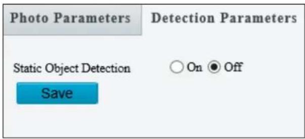
text_image
Photo Parameters Static Object Detection Save Detection Parameters On OffFigure 3-55
■ Static Object Detection: Select On for the camera to detect both static and moving targets and Off to detect moving targets only.
3.7 Events
You can set the camera to generate an alarm upon motion detection, tampering alarm, audio detection and one-key shielding linkage.
3.7.1 Motion Detection
Motion detection is used to generate an alarm whenever movement occurs in the specified area.
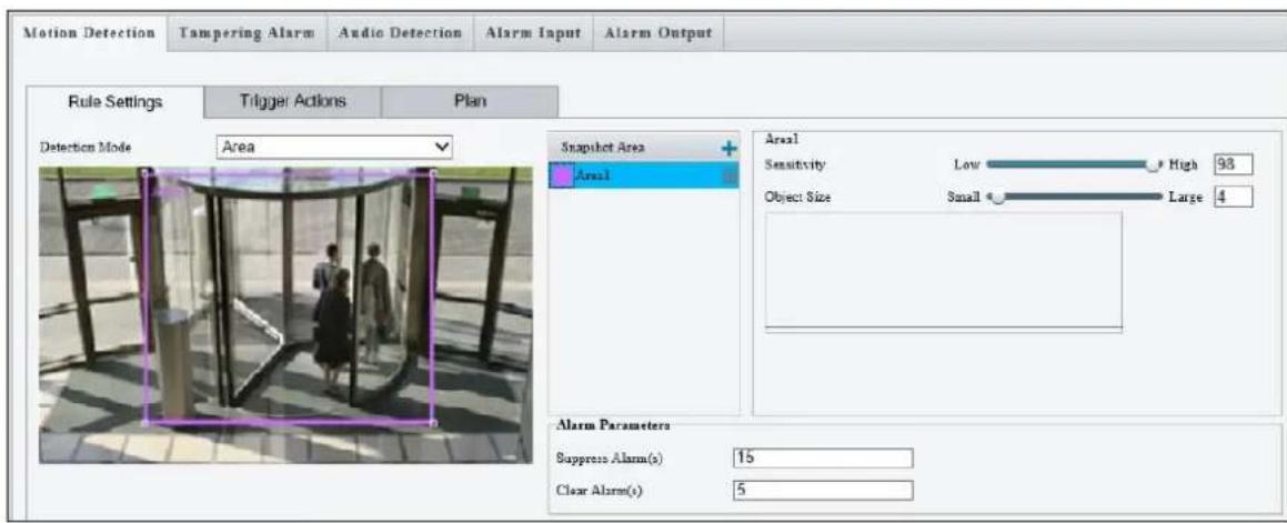
text_image
Motion Detection Tampering Alarm Audio Detection Alarm Input Alarm Output Rule Settings Trigger Actions Plan Detection Mode Area Snapshot Area Area1 Area1 Sensitivity Low High 98 Object Size Small Large 4 Alarm Parameters Suppress Alarm(s) 15 Clear Alarm(s) 5Figure 3-56
-
In the Detection Area, click + to create a new detection area.
-
Click and drag the detection area to a desired location.
-
Alternatively, select Grid as the Detection Mode to define the area for detection.
-
Use the following functions to reduce false alarm.
-
Sensitivity: Move the slider to adjust the detection sensitivity.
Object Size: When the extent of motion within the detection area exceeds the set object size, motion detection alarm is triggered. -
Set up Alarm Parameters.
■ Suppress alarm (5\~3600): After an alarm is triggered, the alarm will not be reported within the set time.
■ Clear alarm (1\~600): After an alarm is triggered,
- If the alarm is not triggered within the set time, the alarm will be cleared and the alarm can be reported again.
- If the alarm is triggered within the set time, the alarm will not be cleared until the suppress alarm time expires. Then the alarm can be reported again.
- For Trigger Actions and Plan, follow Step 6 \~ 7 at the bottom of 3.6.1.1 Cross Line.
Note:
- GV-ABL2703 series / 4703 / 4711, GV-ADR2702 / 4702, GV-BLFC5800, GV-EBD2704 / 4701 / 4704 / 4712 / 4813 / 8800 / 8813, GV-EBFC5800, GV-PTZ5810-IR, GV-TBL2703 series / 2705 / 4700 / 4703 / 4705 / 4711 / 4810 / 8710 / 8804 / 8810, GV-TDR2702 series / 2704 series / 4702 series / 4703 series / 4704 series / 4803 series / 8805, GV-TFD4700 / 4800, GV-TVD4700 / 4711 / 4810 / 8810, and GV-FER5702 support up to 4 Motion Detection areas while all other models support up to 8.
- For the Upload to FTP function, make sure to configure the settings in 3.8.2 FTP and 3.3.2 Snapshot first.
- For the Trigger E-mail function, make sure to configure the settings in 3.2.5 E-mail and 3.3.2 Snapshot first.
- The Alarm Output option (under Trigger Actions) is not supported by GV-EBD2704 / 4701 / 4704 / 4712 / 8800 / 8813, GV-EBFC5800, GV-TBL2705 / 4700 / 4705 / 8804, GV-TDR2704 series / 4704 series, and GV-TVD4700.
3.7.2 Tampering Alarm
Note this function is only applicable to GV-ABL2702 / 2703 series / 4703 / 4711 / 4712 / 8712, GV-ADR2700 / 4710 / 8710, GV-AVD2700 / 4710 / 8710, GV-BLFC5800, GV-EBD series, GV-EBFC5800, GV-PTZ5810-IR, GV-TBL series, GV-TDR series, GV-TFD4700 / 4800, GV-TVD series, and GV-FER5702.
Tampering alarm is used to detect when the camera is being physically tampered with. An alarm can be generated when the camera is moved, covered up, or out of focus.

text_image
Motion Detection Tampering Alarm Audio Detection Alarm Input Alarm Output Tampering Alarm On Off Rule Settings Trigger Actions Plan Sensitivity 50 Duration(s) 1 SaveFigure 3-57
- Select On to enable Tampering Alarm.
- Use the following functions to adjust the alarm settings.
- Sensitivity: Move the slider to increase or decrease detection sensitivity.
- Duration: Specify the duration of the alarm after which the triggered output device will be turned off.
- For Trigger Actions and Plan, follow Step 6 \~ 7 at the bottom of 3.6.1.1 Cross Line.
Note: The Alarm Output option (under Trigger Actions) is NOT supported by GV-EBD2704 / 4701 / 4704 / 4712 / 8800 / 8813, GV-EBFC5800, GV-TBL2705 / 4700 / 4705 / 8804, GV-TDR2704 series / 4704 series, and GV-TVD4700.
3.7.3 Audio Detection
Note this function is only applicable to audio-in-supporting models.
Audio detection is used to detect abnormal audio volume. When the rise, fall, or change of volume exceeds the set limit, or when the input volume reaches the set threshold, an alarm is generated. Make sure audio input is enabled.
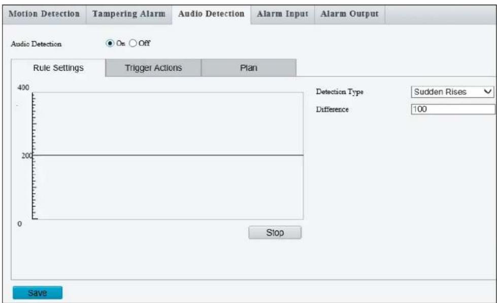
text_image
Motion Detection Tampering Alarm Audio Detection Alarm Input Alarm Output Audio Detection On Off Rule Settings Trigger Actions Plan 400 200 0 Stop Sudden Rises Detection Type 100 Difference SaveFigure 3-58
- Select On to activate Audio Detection.
-
Select a Detection Type.
-
Sudden Rises: An alarm is reported when the rise of volume exceeds the set Difference.
- Sudden Fall: An alarm is reported when the fall of volume exceeds the set Difference.
-
Sudden Change: An alarm is reported when the rise or fall of volume exceeds the set Difference.
Threshold: An alarm is reported when the volume exceeds the set Threshold. -
Set a Difference or Threshold.
-
For Trigger Actions and Plan, follow Step 6 \~ 7 at the bottom of 3.6.1.1 Cross Line.
Select the actions to be triggered by an audio alarm and set a schedule plan if needed. Refer to 3.7.1 Motion Detection for detailed instructions.
3.7.4 Alarm Input
Note this function is only applicable to GV-ABL2701 Series / 2702 / 4701 Series / 4711 / 4712 / 8712, AVD2700 / 4701 / 8710, GV-BLFC5800, GV-TBL4710 / 4711 / 4810 / 8710 / 8810, GV-TDR2700 series / 4700 series / 4703 series / 4803 series / 8805, GV-TFD4700 / 4800, GV-TVD4710 / 4711 / 4810 / 8710 / 8810, and GV-FER5702.
The camera can receive alarm information from an input device.
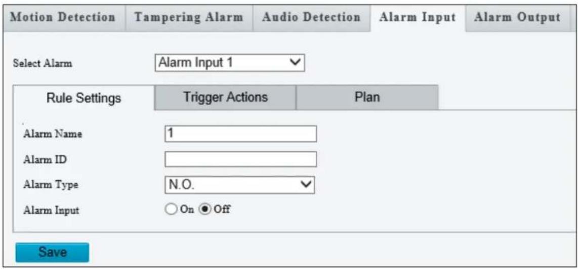
text_image
Motion Detection Tampering Alarm Audio Detection Alarm Input Alarm Output Select Alarm Alarm Input 1 Rule Settings Trigger Actions Plan Alarm Name 1 Alarm ID Alarm Type N.O. ✓ Alarm Input ○ On ● Off SaveFigure 3-59
- Select Alarm Input 1 or Alarm Input 2 from the drop-down list.
- Type an Alarm Name, and set an Alarm ID.
- Select Normally Open or Normally Closed according to the type of the alarm input device.
- Select Enable next to Alarm Input.
- For Trigger Actions and Plan, follow Step 6 \~ 7 at the bottom of 3.6.1.1 Cross Line.
- Click Save.
3.7.5 Alarm Output
Note this function is only applicable to GV-ABL2701 Series / 2702 / 4701 Series / 4711 / 4712 / 8712, AVD2700 / 4701 / 8710, GV-BLFC5800, GV-PTZ5810-IR, GV-TBL4710 / 4711 / 4810 / 8710 / 8810, GV-TDR2700 series / 4700 series / 4703 series / 4803 series / 8805, GV-TFD4700 / 4800, GV-TVD4710 / 4711 / 4810 / 8710 / 8810, and GV-FER5702.
After alarm output is triggered by a motion detection alarm, temperature alarm or input alarm, the camera can trigger an output device.

text_image
Motion Detection Tampering Alarm Audio Detection Alarm Input Alarm Output Select Alarm A → 1 Rule Settings Output Schedule Alarm Name 2 Default Status N.O. ✓ Delay(s) 30 Relay Mode Monostable ✓ SaveFigure 3-60
- Type the Alarm Name for the output device.
- Set the status to Normally Open (default setting).
- Set the alarm duration.
- Set relay mode to trigger the output device as alarm lights. Select Monostable to trigger by pulse or Bistable by low or high level.
- Set a schedule plan in Output Schedule by following Step 7 at the bottom of 3.6.1.1 Cross Line.
- Click Save.
3.7.6 One-Key Shielding Linkage
Note this function is only applicable to GV-BLFC5800, GV-EBD4704 / 4813 / 8800 / 8813, GV-EBFC5800, GV-FER5702, GV-PTZ5810-IR, GV-TBL4705 / 4810 / 8804 / 8810, GV-TDR4704 / 4803 / 8805, GV-TFD4800, and GV-TVD4810 / 8810.
You can disable input / output alarms or e-mails alerts trigger over appointed period of time.
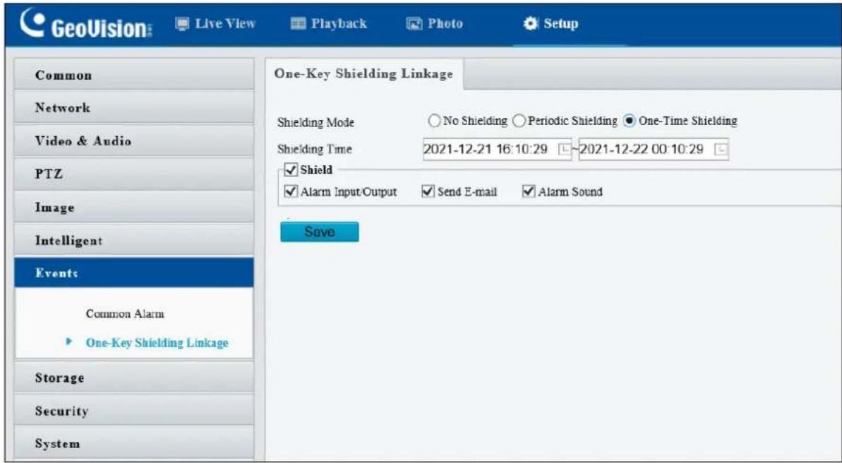
text_image
GeoVision Live View Playback Photo Setup Common Network Video & Audio PTZ Image Intelligent Events Common Alarm One-Key Shielding Linkage Storage Security System One-Key Shielding Linkage Shielding Mode No Shielding Periodic Shielding One-Time Shielding Shielding Time 2021-12-21 16:10:29 ~2021-12-22 00:10:29 Shield Alarm Input/Output Send E-mail Alarm Sound SaveFigure 3-61
- Select No Shielding, Periodic Shielding, or One-Time Shielding under the Shielding Mode. For Period Shielding and One-Time Shielding, set the desired shielding time period under Shielding Time.
- Select Alarm Input / output / Send E-mail / Alarm Sound you wish to disable under Shield.
- Click Save.
3.8 Storage
This section allows you to configure storage related settings and set up FTP server.
3.8.1 Formatting Storage
Note this function is only applicable to GV-ABL2702 / 4712 / 8712, GV-AVD2700 / 4710 / 8710, GV-BLFC5800, GV-EBD2704 / 4701 / 4704 / 4711 / 4712 / 4813 / 8711 / 8800 / 8813, GV-EBFC5800, GV-FER5702, GV-PTZ5810-IR, GV-TBL2705 / 4700 / 4705 / 4710 / 4810 / 8710 / 8804 / 8810, GV-TDR2700 series / 2704 series / 4700 series / 4703 series / 4704 series / 4803 series / 8805, GV-TFD4700 / 4800, and GV-TVD4700 / 4710 / 4810 / 8710 / 8810.
After inserting a memory card, you need to reboot the camera and refresh the Web interface. You can configure the storage settings on the Storage page.
[Storage]
![Geovision 125-TBL8804 - [Storage] - 1](/content/2026/06/1217284/images/954191e2ab27f483bfde3393b557f06dac9681b8c7b9b2a3b575ff1b73c4b96a.jpg)
text_image
Storage Storage Medium Memory Card Format Enable Storage Medium Status: Normal Total Capacity 60890 MB, Free Space 0 MB.Figure 3-62
■ Storage Medium: Click the Format button to format the memory card before you start recording and Enable the memory card.
[Allocate Capacity]
![Geovision 125-TBL8804 - [Allocate Capacity] - 1](/content/2026/06/1217284/images/edd8db0a5541dbf96d30ba8a8f7c9960402638f893d1c2b93c6a57de4b518c39.jpg)
text_image
Allocate Capacity Video(MB) 0 (The remaining capacity is used for image storage.) Common Snapshot(MB) 0 (The remaining capacity is used for Face snapshot storage.) Face Snapshot(MB) 0Figure 3-63
■ Video: Set the storage capacity used to store recorded videos. The remaining capacity is used for captured snapshots.
■ Common Snapshot: The storage capacity used to store captured snapshots.
■ Face Snapshot: The storage capacity used to store captured face snapshots.
■ Intelligent Snapshot: The storage capacity used to store captured snapshots of motor vehicle (cars, trucks, and buses), non-motor vehicle (bicycles and motorcycles), and people.
Note:
- Face Snapshot is only supported by GV-ABL2702 / 4701 / 4712 / 8712, GV-ADR4701, GV-AVD2700 / 4710 / 8710, GV-EBD2702 / 4700 / 4711 / 8700 / 8711, GV-PTZ5810-IR, GV-TBL4710 / 8710, GV-TDR2700 / 4700, GV-TVD4710 / 8710, and GV-SD2722-IR / 3732-IR.
- Intelligent Snapshot is only supported by GV-BLFC5800, GV-EBD4813 / 8800 / 8813, GV-EBFC5800, GV-PTZ5810-IR, GV-TBL4810 / 8804 / 8810, GV-TDR4803 / 8805, GV-TFD4800, and GV-TVD4810 / 8810.
[Video Storage Info]
![Geovision 125-TBL8804 - [Video Storage Info] - 1](/content/2026/06/1217284/images/83bd8fdfe3b2402f78fcb054e2a76e7299a120410a4896bdb6c829752dafcb70.jpg)
text_image
Video Storage Info Storage Policy ● Manual and Alarm Recording ○ Scheduled and Alarm Recording ○ Alarm Recording Only Stream Main Stream When Storage Full ○ Overwrite ● Stop Post-Record(s) 60Figure 3-64
■ Storage Policy: Choose the Storage Policy from the three options.
■ Manual and Alarm Recording: Manually start recording and upon input-triggered events.
■ Scheduled and Alarm Recording: Start recording by schedule and upon input-triggered events.
■ Alarm Recording Only: Start recording upon input-triggered events.
Note: The file size of more than 500 MB is required to create one recording file.
Note for GV-ABL4711, GV-EBD2704 / 4701 / 4712, GV-TBL2705 / 4700 / 4711, GV-TDR2704 series / 4703 series, GV-TFD4700, and GV-TVD4700 / 4711, the options for Storage Policy are as follows:
■ Manual Storage: Manually start recording.
■ Planned Storage: Start recording by schedule.
■ Off: Stop recording.
■ Stream: Select the stream you want to use for recording.
■ When Storage Full:
■ Overwrite: If there is no free space in the memory card, new data will overwrite the existing date repeatedly.
■ Stop: If there is no free space in the memory card, new data will not be saved to the memory card.
Note: This function is NOT applicable to GV-ABL4711 / TBL4711 / TFD4700 / TVD4711.
■ Post Record(s): When an alarm is raised, the camera is triggered to record live video and continues recording for the specified post-record time after the alarm is cleared.
3.8.2 FTP
After the configuration of FTP, you will be able to upload snapshots from the camera to the specified FTP server.
General
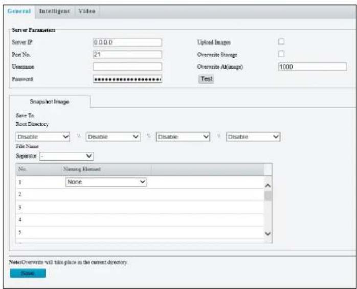
text_image
General Intelligent Video Server Parameters Server IP 0.0.0 Port No. 21 Username Password ************ Upload Images Overwrite Storage Overwrite Alt(image) 1000 Test: Snapshot Image Save To Root Directory Disable Disable Disable Disable File Name Separator - No. Naming Element 1 None 2 3 4 5 Note Overwrite will take place in the current directory. BrowseFigure 3-65
- Type the Server IP address.
- Change the Port No. of the FTP server if needed.
- Type the Username and Password of the upload account.
- Enable Upload Images.
- Select Overwrite Storage to overwrite the oldest images when the storage is full. You can set the maximum number of images allowed in Overwrite At (Image). When the defined image threshold is reached, the oldest image is overwritten.
- Save To Root Directory: Select a directory in which to save the images, or select Custom to name a storage folder on the FTP server.
- Under File Name, select a Separator and a combination of Naming Element(s) to name the snapshots captured. A template of the file name is shown.
- Click Save.
Note:
- To upload snapshots, make sure to enable the Snapshot function. For more detailed instructions, refer to 3.3.2 Snapshot.
- If Overwrite Storage is not selected and the storage is full, snapshots can no longer be taken.
Face (Intelligent)
This function is used to store snapshots taken for smart functions such as face detection. For GV-BLFC5800, GV-EBD4813 / 8800 / 8813, GV-EBFC5800, GV-PTZ5810-IR, GV-TBL4810 / 8804 / 8810, GV-TDR4803 series / 8805, GV-TFD4800, and GV-TVD4810 / 8810, this function is named Intelligent to store captured snapshots of motor vehicle (cars, trucks, and buses), non-motor vehicle (bicycles and motorcycles), and people.
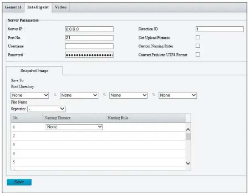
text_image
General Intelligent Video Server Parameters Server IP 0.0.0 Direction ID 1 Port No. 21 Not Upload Pictures Username Custom Naming Rules Password *********. Convert Path into UTF6 Format Snapshot Image Save To Root Directory None None None None File Name Separator - No. Naming Element Naming Rule 1 None 2 3 4 5 SaveFigure 3-66
- Type the Server IP address.
- Change the Port No. of the FTP server if needed.
- Type the Username and Password of the upload account.
- Save To Root Directory: Select a directory in which to save the images, or select Custom to name a storage folder on the FTP server.
- Under File Name, select a Separator and a combination of Naming Element(s) to name the snapshots captured. A template of the file name is shown.
Note: This function is NOT supported by GV-ABL4711, GV-EBD2704 / 4701 / 4704 / 4712, GV-TBL2705 / 4700 / 4705 / 4711, GV-TDR2704 series / 4703 series / 4704 series, GV-TFD4700, GV-TVD4700 / 4711, and GV-FER5702.
3.8.3 Backing Up Storage
Note this function is only applicable to Internet Explorer browsers.
In the Photo setting, you can back up the existing videos and snapshots to your local PC.
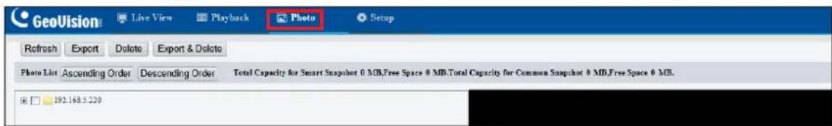
text_image
GeoVision Live View Playback Photo Setup Refresh Export Delete Export & Delete Photo List Ascending Order Descending Order Total Capacity for Smart Snapshot 0 MB,Free Space 0 MB,Total Capacity for Common Snapshot 0 MB,Free Space 0 MB. 192.168.5.220Figure 3-67
- Select Photo at the top of the Web interface and click Refresh.
- Click Ascending Order or Descending Order to sort the folders.
- Click to view more folders and select or deselect the folders to back up.
- Click Export and select a destination to store the selected folders.
- Click Delete to delete the selected folders.
3.9 Security
This section allows you to create user accounts and set the network security settings.
3.9.1 User
There are two types of accounts: Administrator and Common User.
■ Administrator: Admin has full permission and can manage all users and devices. Only one admin account is allowed in the system.
■ Common User: Common User only has permission to play live and recorded video. Up to 31 common users are allowed in the system.
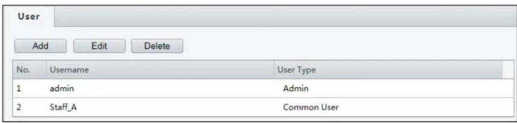
text_image
User Add Edit Delete No. Username User Type 1 admin Admin 2 Staff_A Common UserFigure 3-68
Note:
- The Username of the Admin account cannot be modified.
- Changing the username or password of a user while the user is logged in will force the user to log out. The user must use the new username or password to log in.
- You can also configure User under Common for GV-ABD1300, ABL2701, ADR1300, BLFC5800, EBD4700 / 8711, EBFC5800, TBL2705 / 4700 / 4701 / 8804, TDR2700 / 2704 / 8805, and TFD4700 / 4800.
3.9.2 Network Security
There are five types of network security settings: HTTPS, Authentication, ARP Protection, IP Address Filtering and Access Policy.
HTTPS
You can enable the Hypertext Transfer Protocol Secure (HTTPS) settings to access the camera through a secure protocol. Click On to enable, and optionally click Browse to locate an SSL certificate from your local computer and click Upload.

text_image
HTTPS Authentication ARP Protection IP Address Filtering Access Policy HTTPS ○ On ● Off SSL Certificate Browse... Upload SaveFigure 3-69
Authentication
RTSP (Real Time Streaming Protocol) and HTTP (Hypertext Transfer Protocol) are different application layer protocols for transmitting video. Set the Authentication mode for RTSP streaming or HTTP streaming.
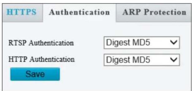
text_image
HTTPS Authentication ARP Protection RTSP Authentication Digest MD5 ✓ HTTP Authentication Digest MD5 ✓ SaveFigure 3-70
For RTSP command, see Appendix B. For HTTP command, see Appendix C.
ARP Protection
This function can protect the camera from ARP attacks. When the camera visits an IP of another network segment via a gateway, it can only communicate with the MAC address binding to the gateway address in the same segment.

text_image
HTTPS RTSP Authentication ARP Protection ARP Protection ● On ○ Off Gateway 192.168.0.1 Gateway MAC Address 0 SaveFigure 3-71
- Select On to enable ARP Protection.
- Type Gateway MAC Address.
- Click Save.
IP Address Filtering
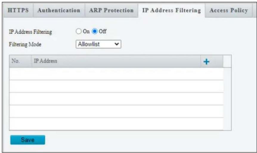
text_image
HTTPS Authentication ARP Protection IP Address Filtering Access Policy IP Address Filtering ○ On ● Off Filtering Mode Allowlist No. IP Address + SaveFigure 3-72
- Select On to enable IP Address Filtering.
- Choose a Filtering Mode: Allowlist or Deny Access.
- Click to add an IP address.
- Click to delete an IP address.
- Click Save.
Access Policy
Access Policy measures the strength of account passwords upon login.
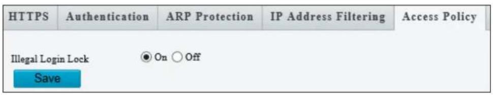
text_image
HTTPS Authentication ARP Protection IP Address Filtering Access Policy Illegal Login Lock On Off SaveFigure 3-73
By enabling Illegal Login Lock, the camera will apply a 5-minute account lockout duration after 5 failed login attempts.
3.10 System
This section allows you to set the camera time and update the firmware.
3.10.1 Time
You can use the following methods to adjust the system time of your camera.
Time

text_image
Time DST Sync Mode Sync with Latest Server Time Time Zone (UTC+08:00) Beijing, Hong Kong, Urumqi, Singapore, Taipei, Perth System Time 2020-05-13 14:45:45 Set Time 2020-05-13 14:45:31 Sync with Computer Time SaveFigure 3-74
1. Select a Sync Mode.
■ Sync with System Configuration: Select a Time Zone, manually set a time by clicking on the System Time, or synchronize with the computer time.
■ Sync with NTP Server: To synchronize with a network time server, type the IP address of the network time server next to NTP Server Address and specify the Update Interval.
■ Sync with Management Server (ONVIF): The device time is synchronized with Management Server (ONVIF).
■ Sync with Latest Server Time: The device time is synchronized with the latest updated time, either on ONVIF or the Web interface.
2. Select a Time Zone.
-
Next to System Time, manually set the camera's time or click Sync with Computer Time to synchronize with the time of your PC.
-
Click Save.
DST
To adjust the camera's time for daylight saving time:
- Click the DST tab at the top.
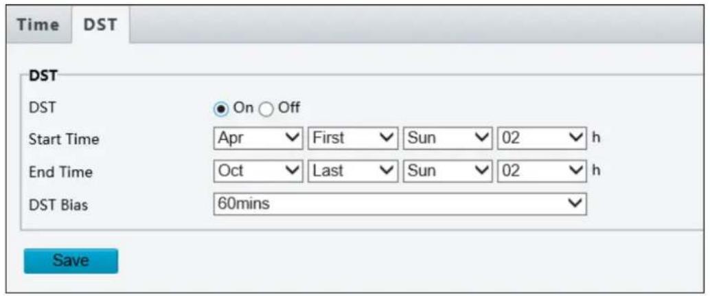
text_image
Time DST DST On Off Start Time Apr First Sun 02 h End Time Oct Last Sun 02 h DST Bias 60mins SaveFigure 3-75
- Select On to enable DST.
- Set a Start Time and End Time for the Daylight Saving Time.
- Select a time period for DST Bias.
- Click Save.
Note: You can also configure Time under Common for GV-ABD1300, ABL2701, ADR1300, BLFC5800, EBD4700 / 8711, EBFC5800, TBL2705 / 4700 / 4701 / 8804, TDR2700 / 2704 / 8805, and TFD4700 / 4800.
3.10.2 Server
Note this function is only applicable to GV-BLFC5800, GV-EBD4813 / 8800 / 8813, GV-EBFC5800, GV-PTZ5810-IR, GV-TBL4810 / 8804 / 8810, GV-TDR4803 / 8805, GV-TFD4800, and GV-TVD4810 / 8810.
Server allows you to quickly access the FTP setting page. Click the FTP button to go to the FTP settings page and complete the storage settings. See 3.8.2 FTP for details.
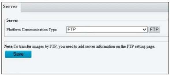
text_image
Server Server Platform Communication Type FTP FTP Note:To transfer images by FTP, you need to add server information on the FTP setting page. SaveFigure 3-76
Note: You can also configure Server under Common for GV-BLFC5800, EBD4700 / 8711, EBF5800, TBL4710 / 8804, TDR2700 / 8805, and TFD4800.
3.10.3 Maintenance
This section allows you to upgrade the firmware, restart the camera, and backup/import camera configurations.
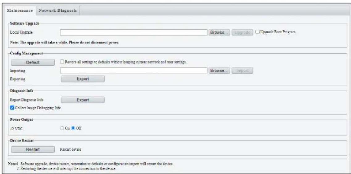
text_image
Maintenance Network Diagnosis Software Upgrade Local Upgrade Browse... Upgrade Upgrade Boot Program Note: The upgrade will take a while. Please do not disconnect power. Config Management Default Restore all settings to defaults without keeping current network and user settings. Importing Browse... Import Exporting Export Diagnosis Info Export Diagnosis Info Export Collect Image Debugging Info Power Output 12 VDC On Off Device Restart Restart Restart device Note:1. Software upgrade, device restart, restoration to defaults or configuration import will restart the device. 2. Restarting the device will interrupt the connection to the device.Figure 3-77
[Software Upgrade]
For detailed instructions, refer to 4.1 Upgrading System Firmware and 4.1.1 Using the Web Interface.
[Config Management] Export the current configurations of the camera and save them to the PC or an external storage medium. You can also quickly restore configurations by importing backup configurations stored on the PC or an external storage medium back to the camera.
[Diagnosis Info] Includes logs and system configurations. Click Browse to select a destination folder on your PC and then Export to save diagnostic information.
[Power Output] Click On to enable 12V DC power output. Note this is only applicable to GV-TFD4800 and TVD-4810 / 8810.
[Device Restart] Click Restart to restart the device after you confirm the operation.
3.10.4 Network Diagnosis
Note this function is only applicable to GV-BLFC5800, GV-EBD4704 / 4813 / 8800 / 8813, GV-EBFC5800, GV-FER5702, GV-PTZ5810-IR, TBL4705 / 4810 / 8804 / 8810, TDR4704 / 4803 / 8805, and TVD4810 / 8810.
This section allows personnel to examine your network environment.
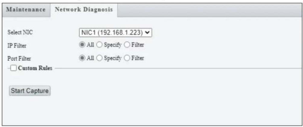
text_image
Maintenance Network Diagnosis Select NIC NIC1 (192.168.1.223) IP Filter All Specify Filter Port Filter All Specify Filter Custom Rules Start CaptureFigure 3-78
3.10.5 Log
Note this function is only applicable to GV-BLFC5800, GV-EBD4704 / 4813 / 8800 / 8813, GV-EBFC5800, GV-FER5702, GV-PTZ5810-IR, TBL4705 / 4810 / 8804 / 8810, TDR4704 / 4803 / 8805, GV-TFD4800, and TVD4810 / 8810.
Log allows you to inquire configurations made on the camera and export the information to the local PC.
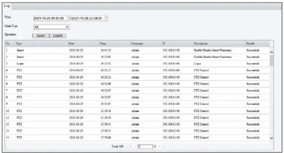
text_image
Log Time 2021-10-29 00:00:00 -2021-10-29 23:59:59 Main Type All Operation Query Export No. Type Date Time Username ID Description Result 1 Smart 2021-10-20 16:41:10 admin 192.168.0.148 Enable Disable Smart Functions Succroed. 2 Smart 2021-10-20 16:23:05 admin 192.168.0.148 Enable Disable Smart Functions Succroed. 3 Login 2021-10-20 16:22:52 admin 192.168.0.148 Login Succroed. 4 PTZ 2021-10-20 16:12:12 admin 192.168.0.148 PTZ Control Succroed. 5 PTZ 2021-10-20 16:12:12 admin 192.168.0.148 PTZ Control Succroed. 6 PTZ 2021-10-20 16:12:08 admin 192.168.0.148 PTZ Control Succroed. 7 PTZ 2021-10-20 16:12:07 admin 192.168.0.148 PTZ Control Succroed. 8 PTZ 2021-10-20 16:12:07 admin 192.168.0.148 PTZ Control Succroed. 9 PTZ 2021-10-20 16:12:07 admin 192.168.0.148 PTZ Control Succroed. 10 PTZ 2021-10-20 15:59:18 admin 192.168.0.148 PTZ Control Succroed. 11 PTZ 2021-10-20 15:59:18 admin 192.168.0.148 PTZ Control Succroed. 12 PTZ 2021-10-20 15:59:13 admin 192.168.0.148 PTZ Control Succroed. 13 PTZ 2021-10-20 15:59:13 admin 192.168.0.148 PTZ Control Succroed. 14 PTZ 2021-10-20 15:59:06 admin 192.168.0.148 PTZ Control Succroed. Total 100 : [ ]Figure 3-79
3.10.6 Ports and Devices
Note this function is only applicable to GV-PTZ5810-IR.
This section allows you to exchange data with a third-party device with the RS485 serial port. Note that the serial setting on the camera should match that of the connected third-party device.

text_image
Serial Port RS485_1 Port Mode Trans-Channel Baud Rate 9600 Data Bits 8 Stop Bits 1 Parity None Flow Control None Enable Trans-Channel SaveFigure 3-80
[Port Mode]
■ Transparent Channel: Select Trans-Channel from the drop-down list of Port Mode to achieve a transparent data transmission with a third-party device.
■ OSD: Select OSD from the drop-down list of Port Mode to display information from a third-party device. This mode allows the camera to receive information from the third-party device through the RS485 serial port, translate the received information, and display it on the local OSD.
■ Local PTZ Control: Select Local PTZ Control from the drop-down list of Port Mode. This mode allows you to control a local PTZ camera through a third-party device without having to use the local camera's PTZ control panel.
■ ONVIF Transparent Channel: Select Trans-Channel via ONVIF from the drop-down list of Port Mode. This mode allows you transmit data through ONVIF transparent channel between the camera's RS485 port and a third-party device.
Chapter 4 Advanced Applications
This chapter introduces more advanced applications.
4.1 Upgrading System Firmware
GeoVision periodically releases updated firmware on the company website. The new firmware can be loaded into the camera using the Web interface or GV-IP Device Utility.
Important Notes before You Start
Before you start updating the firmware, please read these important notes:
- If you use GV-IP Device Utility for firmware upgrade, the computer used to upgrade firmware must be under the same network as the camera.
- Stop monitoring on the camera.
- Stop the camera's connection to GV-VMS / DVR / NVR and all remote connections.
- While the firmware is being updated, the power supply must not be interrupted.
- If firmware upgrade fails, you will need to restore the camera back to its default settings. For details, see 4.2 Restoring to Factory Default Settings.
WARNING:
- The interruption of power supply during updating causes not only update failures but also damages to your camera. In this case, please contact our sales representatives and send your device back to GeoVision for repair.
- It is not suggested to downgrade firmware since it may cause unpredictable issues.
4.1.1 Using the Web Interface
Log into the Web interface and follow the steps below to update the firmware.
- At the top, click Setup.
- In the left menu, select System and select Maintenance. This page appears.
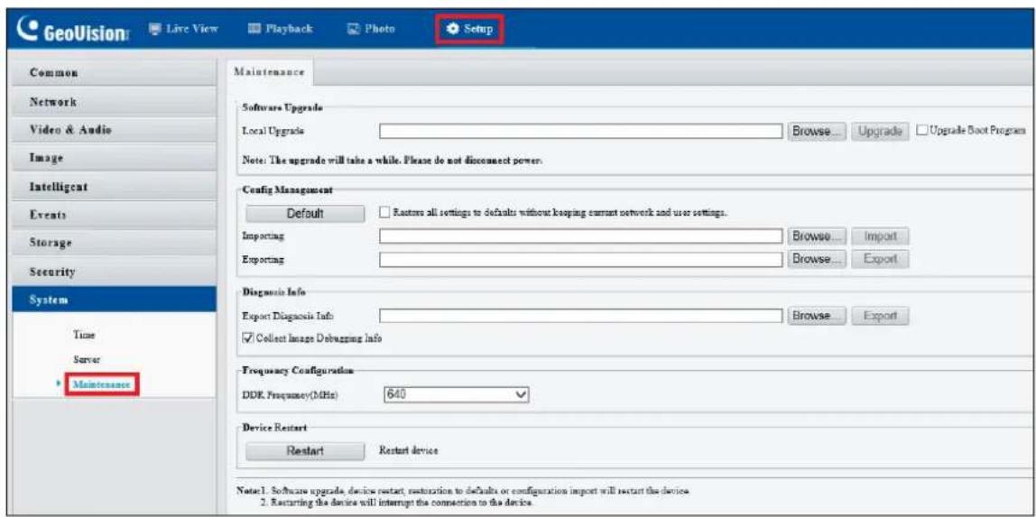
text_image
GeoVision Live View Playback Photo Setup Common Network Video & Audio Image Intelligent Events Storage Security System Time Server Maintenance Maintenance Software Upgrade Local Upgrade Browse... Upgrade Upgrade Boot Program Note: The upgrade will take a while. Please do not disconnect power. Config Management Default Restore all settings to defaults without keeping current network and user settings. Importing Browse... Import Exporting Browse... Design Info Export Diagnosis Info Browse... Export Collect Image Debugging Info Frequency Configuration DDK Frequency(MHz) 640 Device Restart Restart Restart device Note:1. Software upgrade, device restart, restorization to defaults or configuration import will restart the device. 2. Restarting the device will interrupt the connection to the device.Figure 4-1
- Click Browse under Software Upgrade to locate the firmware file (.zip) saved at your local computer.
- Click Upgrade to process the upgrade.
4.1.2 Using GV-IP Device Utility
You can upgrade the camera firmware using GV-IP Device Utility. Note the computer used to upgrade firmware must be under the same network as the camera.
- Download GV-IP Device Utility from the company website. Then follow the onscreen instructions to install the program.
- Double-click the GV IP Device Utility icon created on your desktop.
- Click the camera in the list and select Configure.

text_image
GV IP Device Utility File Tool Version General settings | NVR camera settings | Name Mac Address IP Address Firmware Version Internal Temp... Timer NOTE 53 GV-BX2700 0013E20319CA 192.168.0.94 v1.04 2016-06-21 43.5°C 2016/10/4 18:39:3 GV-BX2700 (256M) (P_Ins) 54 SNVER5201314 0013E2FF1641 192.168.0.97 v1.20 2015-10-28 38.0°C 2016/10/4 18:39:2 GV-SNWR1600 55 GV-BX12201 0013E210FB89 192.168.1.108 v1.05 2016-10-04 56.8°C 2016/10/4 18:38:59 GV-BX12201 (512M) 56 GV-EBD4700 0013E2FA11C9 192.168.1.13 v1.04 2016-06-21 43.5°C 2016/10/4 18:39:3 GV-EBD4700 57 GV-BX12201 0013E2FF1A47 192.168.1.1 Web Page 2016/10/4 18:39:1 GV-BX12201 (512M) 58 GV-MFDC1501 0013E20D2C59 192.168.1.7 v1.04 2016-06-21 43.5°C 2016/10/4 18:39:3 GV-MFDC1501(128M) 59 GV-EBL3101 0013E2FF2178 192.168.1.2 Configure 2016/10/4 18:39:17 GV-EBL3101 (256M) (P_Ins) 60 GV-EBL2101 0013E2FFIE8E 192.168.1.204 v1.02 2016-08-23 45.0°C 2016/10/4 18:39:6 GV-EBL2101 (256M) (P_Ins)Figure 4-2
- Type the camera's user name and password to log in.
- Click the Firmware Upgrade tab. This dialog box appears.

text_image
MacAddress 0013E2FA11C9 IP Address 192.108.1.113 User Login User Name admin Password ****** Set IP Address Firmware Upgrade | File ---- Browse... Upgrades CancelFigure 4-3
- Click Browse to locate the firmware file (.zip) saved at your local computer.
- Click Upgrade to start upgrading the firmware.
4.2 Restoring to Factory Default Settings
If for any reason the camera is not responding correctly, you can restore the camera back to its factory default settings using the Web interface or the Default Button.
Note:
- Only GV-EBD4711 / 4712 / 8711 / 8813, GV-ABL2703 series / 4703, GV-AVD2700 / 4710 / 8710, GV-FER5702, GV-PTZ5810-IR, GV-TBL2703 series / 4703 / 8804, GV-TFD4700 / 4800, and GV-TVD4700 / 4710 / 4711 / 8710 / 8810 support a default button. For where the button is on the camera, see the Overview section in their respective chapters.
-
If the default button doesn't respond after pressing for 15 seconds, reboot the camera and try again within 10 minutes of rebooting.
-
In the Web interface, click Setup.
- In the left menu, select System and select Maintenance.
- Under the Config Management section, click Default.
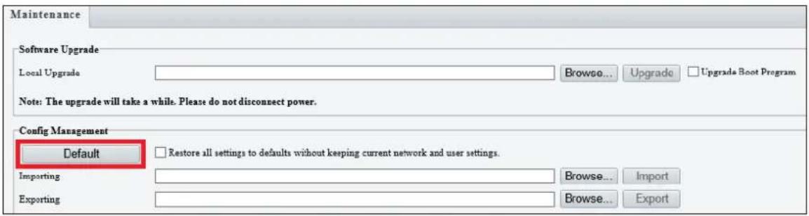
text_image
Maintenance Software Upgrade Local Upgrade Browse... Upgrade Upgrade Boot Program Note: The upgrade will take a while. Please do not disconnect power. Config Management Default Restore all settings to defaults without keeping current network and user settings. Importing Browse... Import Exporting Browse... ExportFigure 4-4
Chapter 5 DVR / NVR / VMS
The GV-VMS / DVR / NVR provides a full range of video management functions and features, such as video viewing, recording, playback, alert settings, and more. The following is a list of related integration specifications:
- For a list of compatible versions of GV-VMS / DVR / NVR based on your camera model, see Appendix D.
- The following lists the maximum throughput and streams when an IP camera is connected to other applications:
| Model | Maximum throughput | Maximum stream(When the total bitrate is within the maximum throughput) | ||
| When connecting to software only | When connecting to software and Web interface | When connecting to Web interface | ||
| GV-ABL4712GV-AVD4710GV-TBL4710GV-TVD4710 | 30 Mbps | 20 | 32 | |
| GV-TDR2704GV-EBD2704GV-TBL2705GV-TDR4704GV-TBL4705GV-EBD4704 | 40 Mbps | 6 | 32 | |
| GV-TFD4800 | 50 Mbps | 20 | 32 | |
| Other models | 40 Mbps | 20 | 32 | |
- When an IP camera is connected to IE browser or any GeoVision CMS application, it takes up 1 stream; when it is connected to GV-VMS / DVR / NVR, it takes up 2 streams.
5.1 Setting Up IP Cameras on GV-DVR / NVR
To set up the camera on GV-DVR / NVR, follow these steps:
- On the main screen, click the Configure button, select System Configure, select Camera Install and click IP Camera Install. This dialog box appears.

text_image
IP Device Setup Server address Port Cam. NO. Status Video Resolution Brand Add Camera Scan Camera Import Camera IP Device Utility Automatic Setup OKFigure 5-1
- To automatically set up the camera, click Scan Camera to detect any camera on the LAN.
- Double-click your camera and type the camera's User name and Password.
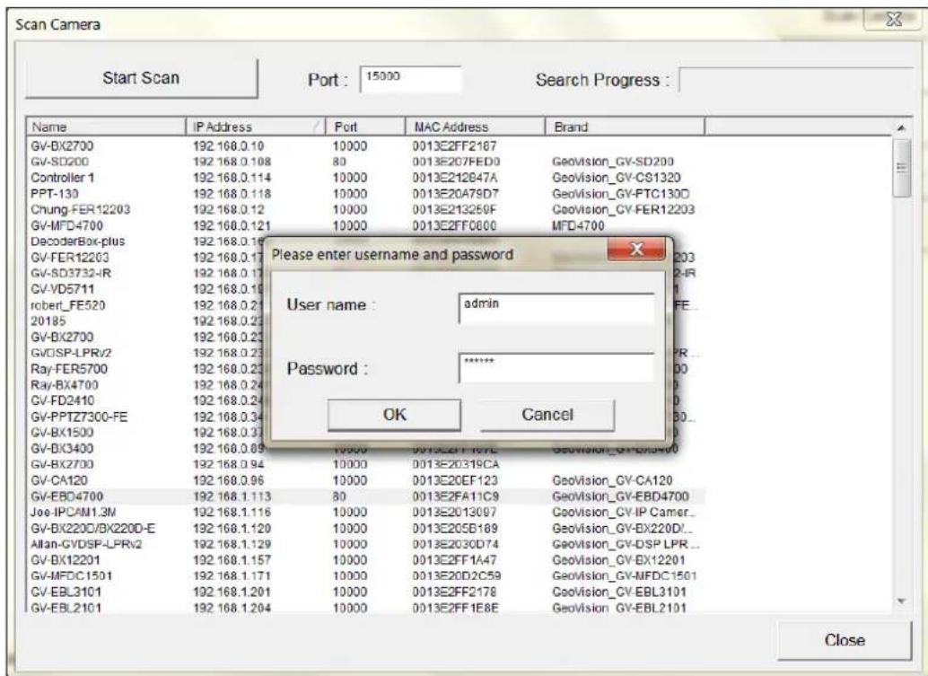
text_image
Scan Camera Start Scan Port: 15000 Search Progress : Name IIP Address Port MAC Address Brand GV-BX2700 192.168.0.10 10000 0013E2FF2167 GV-SD200 192.168.0.108 80 0013E207FED0 GeoVision_GV-SD200 Controller 1 192.168.0.114 10000 0013E212847A GeoVision_GV-CS1320 PPT-130 192.168.0.118 10000 0013E2079D7 GeoVision_GV-FTC130D Chung-FER12203 192.168.0.12 10000 0013E213259F GeoVision_GV-FER12203 GV-MFD4700 192.168.0.121 10000 0013E2FF0600 MFD4700 DecoderBox-plus 192.168.0.16 GV-FER12203 192.168.0.17 GV-SD3732-IR 192.168.0.17 CV-VD5711 192.168.0.19 rober_FE520 192.168.0.21 20185 192.168.0.23 GV-BX2700 192.168.0.23 GV-DSP-LPRv2 192.168.0.23 Ray-FER5700 192.168.0.23 Ray-BX4700 192.168.0.24 CV-FD2410 192.168.0.24 GV-PPTZ730C-FE 192.168.0.34 GV-BX1500 192.168.0.37 GV-BX3400 192.168.0.69 15000 55555555555555555555555555555555555555555555555555555555555555555555555555555 GV-BX2700 192.168.0.94 10000 0013E2FF167E GeoVision_GV-BX2700 GV-CA120 192.168.0.96 10000 0013E20319CA GV-EBD4700 192.168.1.113 80 0013E2FF123 GeoVision_GV-CA120 Joe-IPCAM1.3M 192.168.1.116 10000 0013E2FF169 GeoVision_GV-EBD4700 GV-BX220C/BX220D-E 192.168.1.120 10000 0013E2FF147 GeoVision_GV-IP Camer... Allan-GVDSP-LPRv2 192.168.1.129 10000 0013E2FF2C59 GeoVision_GV-BX220D... GV-BX12201 192.168.1.157 10000 0013E2FF2C78 GeoVision_GV-DSP LPR... GV-MFDCI5OI 192.168.1.171 10000 0013E2FF2C89 GeoVision_GV-EBL3IOLI GV-EBL3IOLI 192.168.1.2OII 10000 0013E2FF2C98 GeoVision_GV-EBL3IOLI GV-EBL2IOLI 192.168.1.2OII 10000 0013E2FF2C99 GeoVision_GV-EBL2IOLI Please enter username and password User name: admin Password:**** OK Cancel CloseFigure 5-2
- Click OK. This dialog box appears.

text_image
Select Profile Single Stream Dual Streams Stream 1 : media_profile1 ... Stream 2 : media_profile2 Information Stream 1 Stream 2 Codec : H264 Codec : H264 Resolution : 2560 x 1440 Resolution : 720 x 576 Quality : 5.000000 Quality : 5.000000 Frame Rate 25 Frame Rate 25 Gov : 50 Gov : 50 Advanced OK CancelFigure 5-3
- Click OK. The IP camera is added to the connection list.
- Click the listed camera and select Display position to map the IP camera to a channel on the GV-DVR / NVR.
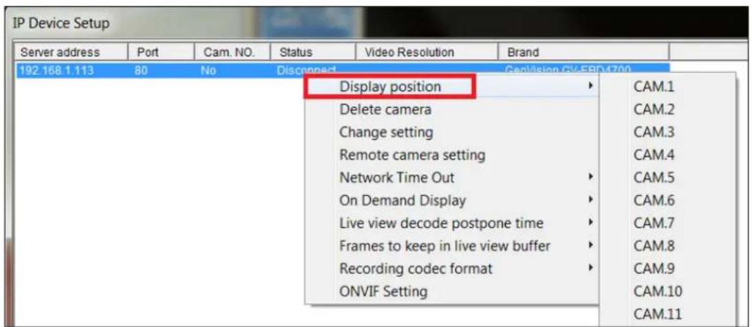
text_image
IP Device Setup Server address Port Cam. NO. Status Video Resolution Brand 192 168.1.113 80 No Disconnect CapVision GV-FBD4700 Display position Delete camera Change setting Remote camera setting Network Time Out On Demand Display Live view decode postpone time Frames to keep in live view buffer Recording codec format ONVIF Setting CAM.1 CAM.2 CAM.3 CAM.4 CAM.5 CAM.6 CAM.7 CAM.8 CAM.9 CAM.10 CAM.11Figure 5-4
- The Statue column should display "Connected". Click OK.
After the camera is connected and assigned with a display position, you can configure the camera's settings, such as frame rate, codec type and resolution. Right-click the desired camera to see the following list of options:

text_image
IP Device Setup Server address Port Cam. NO. Status Video Resolution Brand 102.158 1.113 80 Camera1 Carnered Disconnect camera Change position Delete camera Remote camera setting Network Time Out On Demand Display Live view frame rate control (Sub stream) Live view frame rate control (Main stream) Frames to keep in live view buffer Recording codec format ONVIF Setting Add Camera Scan Camera Import Camera IP Device Utility Automatic Setup OKFigure 5-5
■ Network Time Out: When network disconnection exceeds the specified time period, the camera status displayed as Connection Lost.
■ On-Demand Display: Enable automatic switching between main stream and sub stream based on the size of camera image on screen.
■ Live-view frame rate control (Sub / Main): Set the frame rate of the stream to help reduce the CPU usage. If the codec is set as MJPEG, select the number of frames to allow in a second. If the codec is H.265 or H.264, select one of the following options:
- Maximum Live-view Frame Rate: View the video at the maximum frame rate possible.
Live-view Key Frame only: You can choose to view the key frames of the videos only instead of all frames on the live view. This option is related to the GOP setting of the IP camera. For example, if the GOP value is set to 30, there is only one key frame in every 30 frames.
■ Frames to keep in live view buffer: Specify the number of frames to keep in the live view buffer.
■ Recording Codec Format: Select the codec to record in.
5.2 Setting Up IP Cameras on GV-VMS
Follow the steps below to manually connect your camera to GV-VMS.
- To access the IP Device Setup page, click Home ☐, select Toolbar ✕, click Configure ⚙ and select Camera Install.
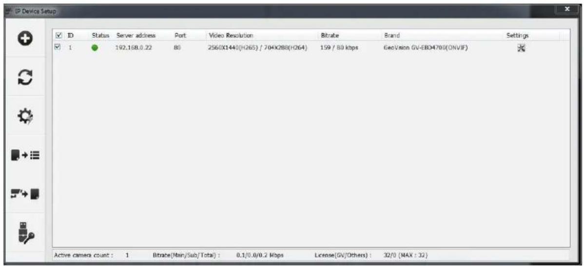
text_image
IP Device Setup ID Status Server address Port Video Resolution Bitrate Brand Settings 1 192.168.0.22 80 2560X1440(H265) / 704X288(H264) 159 / 80 kbps GeoVision GV-EBD4700(ONVIF) Active camera count: 1 Bitrate(Main/Sub/Total): 0.1/0.0/0.2 Mbps License(GV/Others): 32/0 (MAX : 32)Figure 5-6
- Click Automatic Setup

- Double-click the camera and type the User name and Password of the camera.

text_image
Scan Camera Network Adapter : IP[192.168.0.22] Realtek PCIe GBE Family Controller Port : 15000 Start Scan Search Progress : Name IP Address Port MAC Address Brand GV-EBD4700 192.168.0.22 80 0013E2FA11CF GeoVision_GV-EBD4700 GV-FD5700 192.168.3.158 10000 0013E2FF22FB GeoVision_GV-FD5700 Please enter username and password User name: admin Password: OK Cancel CloseFigure 5-7
- Click OK. This dialog box appears.
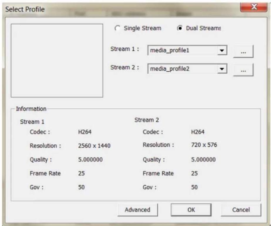
text_image
Select Profile Single Stream Dual Streams Stream 1 : media_profile1 ... Stream 2 : media_profile2 Information Stream 1 Stream 2 Codec : H264 Codec : H264 Resolution : 2560 x 1440 Resolution : 720 x 576 Quality : 5.000000 Quality : 5.000000 Frame Rate 25 Frame Rate 25 Gov : 50 Gov : 50 Advanced OK CancelFigure 5-8
- Click OK to add the camera to the list.
- To connect the added camera, click the box beside the ID column. Upon successful connection, the Status icon shows green, with the video resolution and bitrate being displayed in the correspondent columns.

text_image
ID Status Serve address Port Video Resolution Bitrate Brand Settings 1 192.168.0.22 80 2560X1440(H265) / 704X288(H264) 159 / 80 kbps GeoVision GV-EBD4700(ONVF)Figure 5-9
Appendix
A. RTSP Multicast Protocol Support
The camera supports RTSP multicast protocol for both video and audio streaming. Use the following RTSP multicast command to access the camera images:
Stream 1: rtsp://
Stream 2: rtsp://
For example, rtsp://192.168.4.115/multicast/video1
B. RTSP Protocol Support
The camera can support RTSP protocol for both video and audio streaming. Use the following RTSP command to access the camera image:
Stream 1: rtsp://
Stream 2: rtsp://
For example, rtsp://admin:admin@192.168.3.111/media/video1
Note:
- See 3.9.2 Network Security for RTSP related settings on the Web interface.
- Only VLC and QuickTime players are supported for video streaming via RTSP protocol.
C. HTTP Protocol Support
The camera supports HTTP protocol for accessing snapshots. To obtain a snapshot of the live view, type the following HTTP command on your Web browser:
http://
For example, http://192.168.0.10/images/snapshot.jpg
When the Windows Security dialog box appears, type the camera's user name and password to receive the captured snapshot.
Note: See 3.9.2 Network Security for HTTP related settings on the Web interface.
D. Compatible Versions of GV-VMS / DVR / NVR
Compatible versions of GV-VMS / DVR / NVR based on camera models listed as follows:
| Camera Model | Compatible GV-DVR / NVR | Compatible GV-VMS |
| GV-EBD2702 | V8.7.4.0 with patch files or later | V17.1 with patch files or later |
| GV-EBD2704 | V8.9.1 with patch files or later | V17.4.1 with patch files or laterV18.2.1 with patch files or later |
| GV-EBD4700 | V8.7.3.0 with patch files or later | V16.11.0.0 with patch files or later |
| GV-EBD4701 | V8.9.0 (no patch files required) | V17.4.0 (no patch files required)V18.1.1 with patch files or later |
| GV-EBD4704 | V8.9.1 with patch files or later | V17.4.1 with patch files or laterV18.2.1 with patch files or later |
| GV-EBD4711 | V8.7.4.0 with patch files or later | V16.11.0.0 with patch files or later |
| GV-EBD4712 | V8.9.0 (no patch files required) | V17.4.0 (no patch files required)V18.1.1 with patch files or later |
| GV-EBD4813 | V8.9.1 with patch files or later | V17.4.2 with patch files or laterV18.2.1 with patch files or later |
| GV-EBD8700 | V8.8.0 with patch files or later | V17.1.0.100 with patch files or later |
| GV-EBD8711 | V8.7.4.0 with patch files or later | V17.1 with patch files or later |
| GV-EBD8800 | V8.9.1 with patch files or later | V17.4.1 with patch files or laterV18.2.1 with patch files or later |
| GV-EBD8813 | V8.9.1 with patch files or later | V17.4.1 with patch files or laterV18.2.1 with patch files or later |
| GV-ABL2701 Series | V8.7.4.0 with patch files or later | V16.11.0.0 with patch files or later |
| GV-ABL2702 | V8.7.4.0 with patch files or later | V17.1 with patch files or later |
| GV-ABL2703 | V8.8.0 with patch files or later | V17.2.0 (no patch files required) |
| GV-ABL4701 Series | V8.7.4.0 with patch files or later | V16.11.0.0 with patch files or later |
| GV-ABL4703 | V8.8.0 with patch files or later | V17.2.0 (no patch files required) |
| GV-ABL4711 | V8.8.0 with patch files or later | V17.3.0 with patch files or laterV18.1.1 with patch files or later |
| GV-ABL4712 | V8.7.4.0 with patch files or later | V16.11.0.0 with patch files or later |
| GV-ABL8712 | V8.7.4.0 with patch files or later | V17.1 with patch files or later |
| GV-ADR2701 | V8.7.4.0 with patch files or later | V16.11.0.0 with patch files or later |
| GV-ADR2702 | V8.8.0 (no patch files required) | V17.1.0.100 with patch files or later |
| GV-ADR4701 | V8.7.4.0 with patch files or later | V16.11.0.0 with patch files or later |
| GV-ADR4702 | V8.8.0 (no patch files required) | V17.1.0.100 with patch files or later |
| GV-AVD2700 | V8.7.4.0 with patch files or later | V17.1 with patch files or later |
| GV-AVD4710 | V8.7.4.0 with patch files or later | V16.11.0.0 with patch files or later |
| GV-AVD8710 | V8.7.4.0 with patch files or later | V17.1 with patch files or later |
| GV-TBL2703 Series | V8.8.0 with patch files or later | V17.3.0 with patch files or later |
| GV-TBL2705 | V8.9.1 with patch files or later | V17.4.1 with patch files or laterV18.2.1 with patch files or later |
| GV-TBL4700 | V8.8.0 with patch files or later | V17.3.0 with patch files or laterV18.1.1 with patch files or later |
| GV-TBL4703 | V8.8.0 with patch files or later | V17.3.0 with patch files or later |
| GV-TBL4705 | V8.9.1 with patch files or later | V17.4.1 with patch files or laterV18.2.1 with patch files or later |
| GV-TBL4710 | V8.8.0 with patch files or later | V17.1.0.100 with patch files or later |
| GV-TBL4711 | V8.8.0 with patch files or later | V17.3.0 with patch files or laterV18.1.1 with patch files or later |
| GV-TBL4810 | V8.9.1 with patch files or later | V17.4.2 with patch files or laterV18.2.1 with patch files or later |
| GV-TBL8710 | V8.8.0 with patch files or later | V17.1.0.100 with patch files or later |
| GV-TBL8804 | V8.9.1 with patch files or later | V17.4.1 with patch files or laterV18.2.1 with patch files or later |
| GV-TBL8810 | V8.9.1 with patch files or later | V17.4.1 with patch files or laterV18.2.1 with patch files or later |
| GV-BLFC5800 | V8.9.1 with patch files or later | V17.4.3 with patch files or laterV18.2.1 with patch files or later |
| GV-TDR2700 | V8.7.6.0 with patch files or later | V17.1.0.100 with patch files or later |
| GV-TDR2702 | V8.8.0 with patch files or later | V17.3.0 with patch files or later |
| GV-TDR2704 Series | V8.9.1 with patch files or later | V17.4.1 with patch files or laterV18.2.1 with patch files or later |
| GV-TDR4700 Series | V8.8.0 with patch files or later | V17.1.0.100 with patch files or later |
| GV-TDR4702 | V8.8.0 with patch files or later | V17.3.0 with patch files or later |
| GV-TDR4703 Series | V8.9.0 (no patch files required) | V17.4.0 (no patch files required)V18.1.1 with patch files or later |
| GV-TDR4704 Series | V8.9.1 with patch files or later | V17.4.1 with patch files or laterV18.2.1 with patch files or later |
| GV-TDR4803 Series | V8.9.1 with patch files or later | V17.4.2 with patch files or laterV18.2.1 with patch files or later |
| GV-TFD4700 | V8.9.1 with patch files or later | V17.4.1 with patch files or laterV18.2.1 with patch files or later |
| GV-TVD4700 | V8.8.0 with patch files or later | V17.3.0 with patch files or laterV18.1.1 with patch files or later |
| GV-TVD4710 | V8.8.0 with patch files or later | V17.1.0.100 with patch files or later |
| GV-TVD4711 | V8.8.0 with patch files or later | V17.3.0 with patch files or laterV18.1.1 with patch files or later |
| GV-TVD4810 | V8.9.1 with patch files or later | V17.4.2 with patch files or laterV18.2.1 with patch files or later |
| GV-TVD8710 | V8.8.0 with patch files or later | V17.1.0.100 with patch files or later |
| GV-TVD8810 | V8.9.1 with patch files or later | V17.4.1 with patch files or laterV18.2.1 with patch files or later |
| GV-FER5702 | N/A | V17.4.3 with patch files or laterV18.2.1 with patch files or later |
| GV-PTZ5810-IR | V8.9.1 with patch files or later | V17.4.3 with patch files or laterV18.2.1 with patch files or later |
| GV-EBFC5800 | V8.9.1 with patch files or later | V17.4.4 or laterV18.2.1 with patch files or later |
| GV-TDR8805 | V8.9.1 with patch files or later | V17.4.4 or laterV18.2.1 with patch files or later |
| GV-TFD4800 | V8.9.1 with patch files or later | V17.4.5 or laterV18.3.0 or later |
E. GV-Mount Dimensions
Dimensions of various GV-Mount are illustrated below:
| GV-Mount Models | Dimensions | |
| GV-Mount107 | 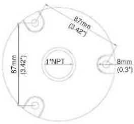 | 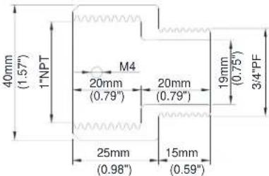 |
 | ||
| GV-Mount211-2 |  | 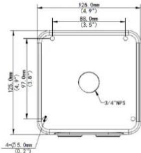 |
| GV-Mount211P | 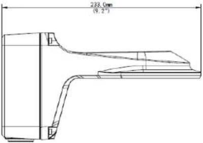 |  |
| GV-Mount212-2 | 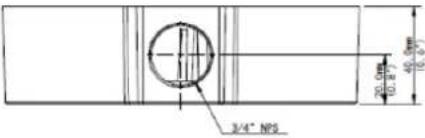 | 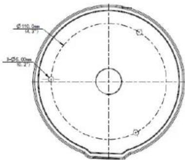 |
| GV-Mount212P | 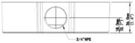  | |
| GV-Mount213 | 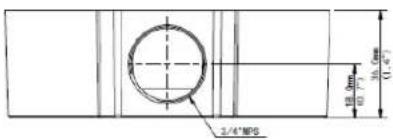  | |
| GV-Mount300-2 | 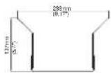 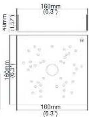  | |
| GV-Mount310-2 | 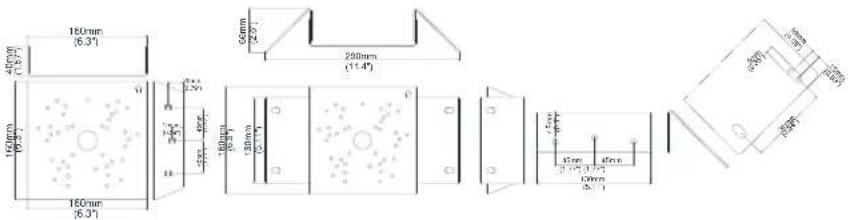 | |
| GV-Mount502 | 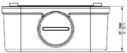 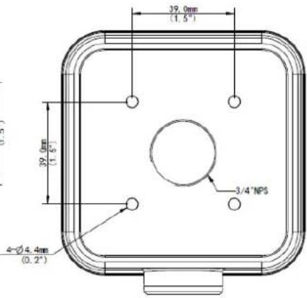 | |
| GV-Mount503 | 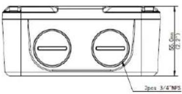 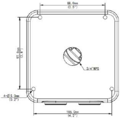 | |
| GV-Mount504 |  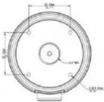 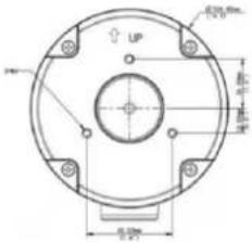 | |
| GV-Mount606 |  | |
| GV-Mount70410/20/30/50cm | 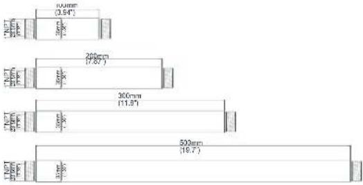 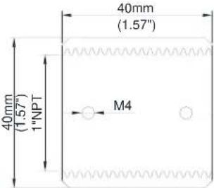 | |
F. GV-Mount300-2 / 310-2
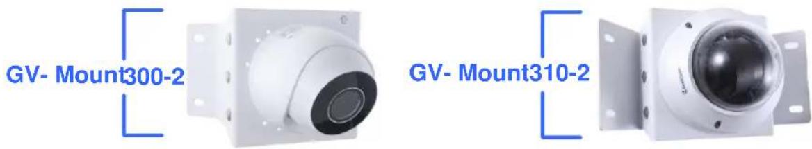
text_image
GV-Mount300-2 GV-Mount310-2GV-Mount300-2 / 310-2 Packing List
Mounting Bracket | Convex Mounting Plate x 2(for GV-Mount300-2)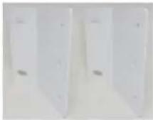 Concave Mounting Plate x 2(for GV-Mount310-2) Concave Mounting Plate x 2(for GV-Mount310-2)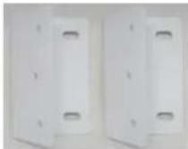 |
Carriage Bolt x 6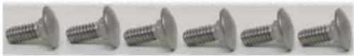 | 1/4" Plain Washer x 6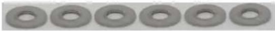 |
1/4" Flange Nut x 6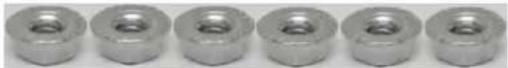 | M4 Screw (25 mm) x 4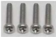 |
M4 Plain Washer x 4 | M4 Flange Nut x 4 |
M3 Screw (15 mm) x 4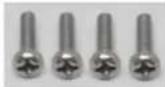 | M3 Plain Washer x 4 |
M3 Flange Nut x 4 |
To install GV-ABL / TBL Series, GV-ADR2702 / 4702, GV-AVD / TVD Series, GV-BLFC5800, GV-EBD Series, GV-EBFC5800, GV-PTZ5810-IR, GV-TDR Series, GV-TFD4700 / 4800, or directly on GV-Mount300-2 / 310-2, follow the instructions below.
-
Assemble the GV-Mount300-2 / 310-2, by attaching the two mounting plates onto the mounting bracket with the supplied carriage bolts, 1/4" plain washers, and 1/4" flange nuts.
-
Thread the camera wires through the hole in the center of the mounting bracket.
-
Position the base of your camera according to the enclosed Screw Position Chart.
-
Attach the camera onto the mounting bracket.
A. For GV-EBD2702 / 2704 / 4700 / 4701 / 4704 / 8700 / 8800 and GV-EBFC5800 Remove the camera housing and attach the camera base to the mounting bracket with the supplied M3 screws, washers, and flange nuts. See similar installation in Step 3 \~ 6, 1.1.4.1 GV-EBD2702 / 2704 / 4700 / 4701 / 4704 / 8700 / 8800 Standard Installation.
B. For GV-EBD4711 / 4712 / 4813 / 8711 / 8813 & GV-PTZ5810-IR Remove the camera housing and attach the camera base to the mounting bracket with the supplied M3 screws, washers, and flange nuts. See similar installation in Step 3 \~ 6, 1.1.4.2 GV-EBD4711 / 4712 / 4813 / 8711 / 8813 Standard Installation.
C. For GV-ABL / TBL Series & GV-BLFC5800 (Not applicable to GV-TBL2705 / 4705 / 8804) Attach the camera to the mounting bracket with the supplied M4 screws, washers, and flange nuts.
D. For GV-ADR2702 / 4702 / GV-TDR Series / GV-TFD4700 / 4800 Attach the camera to the mounting bracket with the supplied M3 screws, washers, and flange nuts. Close and secure the camera housing.
E. For GV-AVD / TVD Series Remove the camera housing and attach the camera base to the mounting bracket with the supplied M4 screws, washers, and flange nuts. See similar installation in Step 3 \~ 4, 1.4.4 Installation.
- Secure the assembled GV-IP Camera and GV-Mount300-2 / 310-2 to the wall with the 4 self-prepared screws with the arrow pointing up.
To install GV-Mount211P / 211-2 / 212-2 / 212P / 213 / 502 / 503 on GV-Mount300-2 / 310-2
- Assemble the GV-Mount300-2 / 310-2, by attaching the two mounting plates onto the mounting bracket with the supplied carriage bolts, 1/4" plain washers, and 1/4" flange nuts.
- Position and secure GV-Mount211P / 211-2 / 212-2 / 212P / 213 / 502 / 503 to GV-Mount300-2 / 310-2 as instructed on the enclosed Screw Position Chart.
- Secure your GV-IP Camera to the GV-Mount211P / 211-2 / 212-2 / 212P / 213 / 502 / 503 to complete the installation.
Note: For details on attaching your GV-IP Camera to GV-Mount211P / 211-2 / 212-2 / 212P / 213 / 502 / 503, see optional installations in Chapter 1 Introduction.
G. Screw Position Chart
| Screws:M4*25GV-Mount502GV-TBL 2703/4703GV-ABL 2701/4701/2703/4703 | Screws:M4*25GV-Mount503GV-Mount211PGV-Mount211-2 | Screws:M4*25GV-Mount212-2 | Screws:M4*25GV-Mount212P | Screws:M4*25GV-Mount213 | |
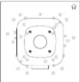 |  |  |  | 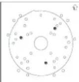 | |
 |  |  |  |  |  |
| Screws:M4*25GV-ABL 2702/4711/4712/8712GV-TBL 4700/4710/4711/4810/S710/S810 | Screws:M3*15GV-ADR2702/4702GV-TFD4700GV-TDR2700/2702/2704/4700/4702/4703/4704/4803 | GV-AVD2700/4710/8710GV-TVD4700/4710/4711/4810/8710/8810 | Screws:M3*15GV-EBD2702/2704 | Screws:M3*15GV-EBD4700/4701/4704/8700/8800 | Screws:M3*15GV-EBD4711/4712/4813/8711/8813 |
| If you cannot find the desired camera model, please visit our website for more information. | |||||
H. Note for Fisheye Camera with IR LED
When installing Mount107 / 211P / 212P to your GV-FER5702, leave a distance of 1 M (3.28 ft) or more between the camera body and nearby walls to avoid reflected glare by IR LED.
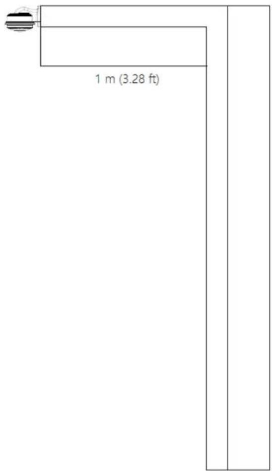
text_image
1 m (3.28 ft)I. Retrieve Camera's Password
You can collect required information and contact our support teams to retrieve your camera's password. Refer to the instructions here
J. Installation Guidelines for Perimeter Protection
To use the functions of Cross Line, Intrusion Detection, Enter Area, and Leave Area, which is only supported by AI-capable cameras, it is recommended to install the camera according to the criteria listed below:
Lighting Requirements
- Lighting at the site must be greater than 50 lux.
- Lighting at the site must be even and stable.
Environmental Requirements
- Mount height: 3 \~ 6 meters.
- Monitoring distance: 6 \~ 30 meters.
- Coverage width: 10 \~ 20 meters with a maximum of 30 meters.
- Avoid strong backlight or front light in outdoor scenes.
- Avoid scenes with strobe or flash illuminators in outdoor scenes.
Note: The mount height, monitoring distance and coverage width are all affected by the object pixel. For motor vehicle/non-motor vehicle/pedestrian, 200 pixels or more is recommended, and it must not be lower than 100 pixels.
Surveillance Illustration
H: Mount height; L: Capture distance; W: Coverage width

text_image
H L WRecommended Scenes
Clear background, even lighting, and installation angle meets the requirement.
Note Recommended Scenes
Complex perimeter, bad environment; large top view angle, causing objects hard to recognize; uneven lighting.
Image Configuration
Use the default parameters of Starlight or Common scene.

text_image
Scenes No. Current Scene Name Auto Switching Setup 1 ●K. Installation Guidelines for People Flow Counting
To use the People Flow Counting function, which is only supported by AI-capable cameras, it is recommended to install the camera according to the criteria listed below:
Installation Considerations
- It is recommended to install the camera at a height of 4 \~ 9 meters (13.1 \~ 29.5 ft) when the overhead angle of the camera is 30°\~60°, and the effective monitoring width is between 1 \~ 8 meters (3.3 \~ 26.2 ft).
- It is recommended to install the camera at a height of 3 \~ 5 meters (9.8 \~ 16.4 ft) when the overhead angle of the camera is 60°\~90°, and the effective monitoring width is between 1 \~ 5 meters (3.3 \~ 16.4 ft).
- Avoid areas that may affect accuracy as far as possible, such as in the detection area there are leaf shaking interference, serious shadow shaking, glass floor tile reflective scenes.
- If the flow of people in the area is too dense and stagnant, if there is a block on the head, it will have an impact on the index. Such scenes should be avoided as far as possible in the detection area.
- The camera should be well fixed, unable to move or shake.
- Input image aspect ratio is required to be 16:9.
- It does not support infrared scenes, strong backlight, dim scenes and night light changing scenes, etc.
- The scene with reflection is not supported, which will cause more false detections. It is recommended to adjust the camera angle to eliminate the reflection.
- When there is unusual weather such as rain, snow and fog, the scene indicators will be greatly affected.
-
All functions are not suitable for scenes with more occlusion and interference.
-
When adjusting the monitoring range and setting business rules, attention should be paid to the pixel size of pedestrian head and shoulder. When the resolution is 1920 x 1080, the pixel size requirements of head and shoulder are: lower limit: 55 x 55; upper limit: 180 x 180; best: 65 x 65 \~ 160 x 160, and other dimensions are converted according to the proportion of single side length of the picture.
| Resolution Ratio | Recommended Min. Pixel | Recommended Max Coverage (width x depth) |
| 1920 x 1080 | 65 x 65 | 12 m x 10 m |
| 2560 x 1440 | 90 x 90 | 12 m x 10 m |
| 3840 x 2160 | 130 x 130 | 12 m x 10 m |
Recommended Scenes
People Flow Counting applicable scenarios: The entrances and exits of shopping malls, parks, squares, escalators, and other places; passages and gates of railway stations and subways. The scene is relatively clean, with few people present and no light, leaves shaking, shadow, or other interference.
Not Recommended Scenes
- The scene where many people gather in the room and basically stop moving.
- There are umbrellas in rainy days.
- The pixels from heads to shoulders of some people occupy too many pixels in the image, which cannot meet the pixel requirements.
- The screen is too dark, and the installation height falls short of the required height.
- The camera installation location is too far from the horizontal distance of the escalator, which does not meet the requirement of 0.5 \~ 2 m.
- The installation position of the camera is tilted, and the detection box is horizontally tilted, which affects the recognition rate.
L. Installation Guidelines for Crowd Density Monitoring
To use the Crowd Density Monitoring function, which is only supported by AI-capable cameras, it is recommended to install the camera according to the criteria listed below:
Installation Considerations
- The scene should be open, wide, without shielding interference and non-dense crowd.
- The effective monitoring width is affected by the depression angle of the camera and the installation height. The higher the installation height, the larger the monitoring range; The larger the depression angle of the camera, the smaller the monitoring scope.
Recommended Scenes
Crowd Density Monitoring is applicable to squares, open places, shelters and places with less Interference and non-dense population.
Not Recommended Scenes
- The camera installation height is low, and the depth of the scene is too deep (that is, the People Flow Counting scene should not be used for the Crowd Density Monitoring).
- The distance is too far, the target is too small.
Note: People Flow Counting is applicable to places such as squares and open places.
Crow Density Monitoring is applicable to places such as roads, entrances and exits.
Installation Requirements
- Installation height: It is recommended between 6 \~ 10m
- Installation position: it is installed in the place with wide vision to avoid backlighting and many light interferences.
-
The camera depression angle: Between 30^ 80^ , the best angle is 45^ 75^
-
Monitoring range: It is related to the focal length and installation height of different lenses. The target size shall meet the requirements of head and shoulder size.

text_image
horizontal line depression angle 30°-80° Camera mounting height 6-10 Meters Horizontal monitoring distance is related to height and AngleM. Installation Guidelines for Face Detection
To use the Face Detection function, which is only supported by AI-capable cameras, it is recommended to install the camera according to the criteria listed below:
Lighting Requirements
- Select a bright scene (with light no less than 100 lux). Scenes with wide dynamic range and backlight are not recommended.
- Lighting at the site must be even and stable.
Note: Illuminators are required if the natural lighting in the scene is lower than 100 lux.
Environmental Requirements
- Mount height: 2.5 \~ 4.5 m.
- Capture distance: 3 \~ 15 m.
-
Angle: It is recommended to install the camera right in front of the passageway, with horizontal deflection angle ≤30^ , the top view angle ≤15^ ( ≤10^ is recommended).
-
Surveillance coverage width:
4MP IPC: ≤4.5m
8MP IPC: ≤6m
-
In outdoor scenes, avoid installing in an east-west direction (avoid strong backlight or front light).
-
Install the camera in a bright spot to capture people coming from the dark for installations at a passageway, entrance or exit, etc.
Note: The surveillance coverage width of the camera is determined by face pixel. It is recommended that the minimum face pixel is no less than 80.

text_image
Width of surveillance area Horizontal line Top view angle θ Camera optical axis Mount height Walking direction(along the ground center line) Surveillance horizontal distanceRecommended Scenes
Face Detection is applicable to turnstile passageway, indoor passageway, and outdoor sidewalk.
Not Recommended Scenes
- Crossroads, turns, and zebra crossings where faces are not captured from the front
- Tilted mount with an excessively large face deflection angle
- Dark scenes in which faces are not clear enough
- Super wide-angle scenes with insufficient face pixel
- Scenes with LED screens in which lighting is unstable due to the LED screen
Special Scenes
- Scenes with WDR or strong backlight: Use curtains or a double-glazed door to avoid WDR or strong backlight.
- Scenes with strong reflection on the ground: Avoid strong light reflections on the ground by laying carpets on the floor or setting up screens.
Note: For special scenes, assessment must be done thoroughly during survey to determine whether solutions can be fully implemented. Scenes that cannot be fully implemented shall be avoided; otherwise, image quality and capture results may not be satisfactory.
Image Configuration
1. Scenes
Scenes: Starlight

text_image
Scenes No. Current Scene Name Auto Switching Setup2. Exposure Parameters
- Exposure Mode: Select Custom.
- Shutter(s): 1/100-1/200 is recommended for the upper limit. Set appropriately according to the face movement speed.
- Gain: It is recommended to set the upper limit to 40. Set appropriately according to the brightness of face.
● Metering Control: Select Face Metering.
● Face Brightness: 50 is recommended. Set appropriately if the captured face is too dark or overexposed.
● Min. Duration(min): 5 is recommended. Set appropriately as required.

text_image
Exposure Exposure Mode Custom Shutter(s) 1/100000 1/150 Gain 0 100 Slow Shutter On Off Slowest Shutter 1/12 Compensation 0 Metering Control Face Metering Face Brightness 50 Min. Duration(min) 5O. Installation Guidelines for Face Detection (Non-AI)
To use the camera's built-in face detection feature (see 3.5.1.7 Face Detection), which is only supported by certain models, it is recommended to install the camera according to the criteria listed below:
Surveillance Condition
- The camera shall be installed at a site with uniform, sufficient lighting, where the face(s) to be detected are fully illuminated.
| Example of Recommended Scene | Example of Non-recommended Scene |
 | 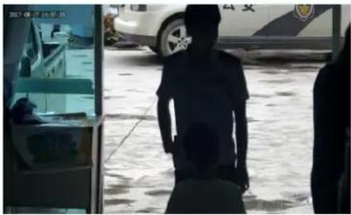 |
Camera Position
- The camera shall be mounted at a recommended height of 2.5 3 ~m (8.2 \~ 9.84 ft).
- The camera shall be mounted with a recommended depression angle of around 10^ .
- The camera shall be positioned so that the face(s) to be detected are directly aligned with the lens of the camera, with a horizontal deviation of no greater than 30^ , a vertical deviation of no greater than 15^ and a face size of at least 120 pixels.
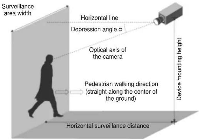
text_image
Surveillance area width Horizontal line Depression angle α Optical axis of the camera Pedestrian walking direction (straight along the center of the ground) Device mounting height Horizontal surveillance distanceP. Installation Guidelines for People Counting (Non-AI)
To use the camera's built-in people counting feature (see 3.5.1.8 People Counting), which is only supported by certain models, it is recommended to install the camera according to the criteria listed below:
Surveillance Condition
- The camera shall be installed at a site with uniform, sufficient lighting, where the person(s) to be counted are fully illuminated.
- The camera shall be installed at an entrance or exit with an ideal width of 1 \~ 4 m (3.28 \~ 13.12 ft), where the persons(s) to be counted move toward the lens of the camera in single file.
| Example of Recommended Scene | Example of Non-recommended Scene |
 |  |
Camera Position
- The camera shall be mounted at a recommended height of 3 5 ~m (9.84 \~ 16.4 ft).
- The camera shall be mounted with a recommended depression angle of 70 80^ .
- The camera shall be positioned so that the person(s) to be counted face toward the lens of the camera and are displayed on the image with a shoulder size of between 120 \~ 160 pixels.
