TCB-SC642TLE2 - Air-conditioner TOSHIBA - Free user manual and instructions
Find the device manual for free TCB-SC642TLE2 TOSHIBA in PDF.

User questions about TCB-SC642TLE2 TOSHIBA
0 question about this device. Answer the ones you know or ask your own.
Ask a new question about this device
Download the instructions for your Air-conditioner in PDF format for free! Find your manual TCB-SC642TLE2 - TOSHIBA and take your electronic device back in hand. On this page are published all the documents necessary for the use of your device. TCB-SC642TLE2 by TOSHIBA.
USER MANUAL TCB-SC642TLE2 TOSHIBA
APPLICATION CONTROL MANUAL
Super Modular Multi System
Heat Pump Type
Cooling Only Type
Super Heat Recovery Multi System
Heat Recovery Type
HFC
R410A
CONTENTS
1 Outline of system and application control
1-1 Outline of application control 5
1-2 List of application control models and setting 6
1-3 Remote controller 7
1-4 Application controls for remote controller 10
1-4-1 Application for indoor remote controller 10
1-4-2 Two remote control 11
1-4-3 Group control 12
1-4-4 Application controls for central remote controller 13
1-5 Application controls of indoor unit 15
1-6 Application controls of outdoor unit 15
1-7 Application controls by optional P.C. board of outdoor unit 16
1-8 Application controls by optional devices connected to indoor unit 19
1-9 Application control for network (Tentative) 21
1-9-1 Touch screen controller system 21
1-9-2 LONWORKS 22
1-9-3 Windows based central controller 23
1-9-4 BACnet 23
2 System wiring diagram and control wiring method
2-1 Applicable model and connectable units 25
2-2 System wiring diagram 26
2-2-1 For VRF system only 26
2-2-2 For combined system with "1:1 model" 27
2-3 Design of control wiring 28
2-4 Earth method of shield wiring 29
2-4-1 For VRF system only 29
2-4-2 For combined system with "1:1 model" 30
2-5 General requirement for control wiring 31
3 Address setup
3-1 Definition of address 34
3-2 Address setup procedure 38
3-2-1 Check at main power-ON 39
3-2-2 Automatic address setup 40
3-2-3 Manual address setup from remote controller 43
3-2-4 Confirmation of indoor unit address and position by using the remote controller 44
3-2-5 Change of indoor address from remote controller 45
3-2-6 Address setup example (VRF system) 47
3-2-7 Clearance of address (Return to status (Address undecided) at shipment from factory) 50
3-2-8 In case of increase the address-undefined indoor units (Extension, etc.) 51
3-2-9 How to set central control address 52
3-2-10 Address re-setup for central control of the super-digital inverter and the digital inverter 54
3-2-11 Indoor address change example (Super-digital inverter and digital inverter) 58
4 Details of application control and devices
4-1 Remote controller 61
4-1-1 Wired remote controller (RBC-AMT21E) 61
4-1-2 Simple remote controller (RBC-AS21E) 67
4-1-3 Wireless remote controller kit 71
4-1-4 Weekly timer (RBC-EXW21E) 97
4-2 Central remote controller (TCB-SC642TLE) 107
4-2-1 Outline 107
4-2-2 Installation procedure 112
4-2-3 Operation procedure 130
4-3 Application controls of indoor unit 136
4-3-1 Setup of selecting function in indoor unit 136
4-3-2 Ventilation fan control from remote controller 139
4-3-3 Leaving-ON prevention control 140
4-3-4 Power peak-cut from indoor unit 140
4-3-5 Remote sensor (TCB-TC21LE) 141
4-4 Application controls of outdoor unit 142
4-4-1 Outdoor fan high static pressure shift 143
4-4-2 Cooling priority, heating priority control 143
4-4-3 Indoor unit setup in "Specific indoor unit priority control" mode 144
4-5 Application controls by optional P.C. board of outdoor unit 145
4-5-1 Power peak-cut control 150
4-5-2 Snowfall fan control 152
4-5-3 External master ON/OFF control 152
4-5-4 Night operation control 153
4-5-5 Operation mode selection control 153
4-6 Application controls by optional devices connected to indoor unit 154
4-6-1 Remote control by "remote location ON/OFF control box" 154
4-6-2 Central control by AI-NETWORK central controller (Network adapter) 157
4-6-3 Central control with "1:1 model" ("1:1 model" connection interface) 163
5 Dimensional drawing
OUTLINE OF SYSTEM
AND
APPLICATION CONTROL
1-1 Outline of application control
1-2 List of application control models and setting
1-3 Remote controller
1-4 Application controls for remote controller
1-4-1 Applications for indoor remote controller
1-4-2 Two remote control
1-4-3 Group control
1-4-4 Application controls for central remote controller
1-5 Application controls of indoor unit
1-6 Application controls of outdoor unit
1-7 Application controls by optional P.C board of outdoor unit
1-8 Application controls by optional devices connected to indoor unit
1-9 Application control for network (Tentative)
1-9-1 Touch screen controller system
1-9-2 LONWORKS
1-9-3 Windows based central controller
1-9-4 BACnet
1-1 Outline of application control
1 BACnet™: ANSI/ASHRAE135-1995, A Data CommuniCation Protocol for Building Automation and Control Networks.
2 LoNWoRKS®: Resistered trademark Echelon Corporation.
1-2 List of application control models and setting
| Appliance name | Model name | Contents of application control | Connecting device or setting method | Reference No. |
| Remote Controller | 1-3 1-4 | |||
| Wired remote controller | RBC-AMT21E | ·Individual control ·Group control ·Two remote control | Indoor unit | |
| Simple remote controller | RBC-AS21E | |||
| Wireless remote controller | TCB-AX21U(W)-E | ·Individual control ·Two wireless control | For 4-way sir discharge cassette type | |
| RBC-AX22CE | For under ceiling type | |||
| TCB-AX21E | ·Two remote control (wired & wireless) | For other type | ||
| Weekly timer | RBC-EXW21E | ·Weekly schedule operation (main remote controller + weekly timer) | Wired remote controller | |
| Central remote controller | TCB-SC642TLE | ·Central control of Max.64 or units | Outdoor unit (Indoor unit) | |
| ·Weekly schedule operation (central remote controller + weekly timer) | ||||
| ·Central control without indoor remote controller | ||||
| ·Central control with "1:1 model" | ||||
| Application controls of indoor unit | 1-5 | |||
| Function change of indoor unit | Setting functions necessary to perform applied control at the local site. | Item code (DN) setting from wired remote controller | ||
| Ventilation fan control from remote controller | Ventilation fan start/stop operation from wired remote controller. | Setting from wired remote controller and relay wiring (local supply) | ||
| Leaving-ON prevention control | Control to prevent Leaving-ON of indoor unit. | |||
| Demand control from indoor unit | Thermo-OFF operation by relay signal | Relay wiring (local supply) | ||
| Remote sensor | TCB-TC21LE | Remote sensing of indoor air temperature | Indoor unit | |
| Application controls of outdoor unit | 1-6 | |||
| Outdoor fan high static pressure shift | Change of outdoor fan control when connecting a duct to discharge port of outdoor unit. | Switch setting on outdoor interface P.C. board | ||
| Control for cooling/heating priority | Change operation mode priority | |||
| Specific indoor unit priority control | Specific indoor unit has the priority for operation mode. | Item code (DN) setting from wired remote controller | ||
| Optional P.C. board of outdoor unit | 1-7 | |||
| Power peak-cut control board | TCB-PCDM2E | Power peak-cut (Standard function) | Inverter assembly of the header outdoor unit | |
| Power peak-cut (Expansion function) | ||||
| External master ON/OFF control board | TCB-PCMO2E | Snowfall fan control | ||
| External master ON/OFF control | ||||
| Night operation (sound reduction) control | ||||
| Operation mode selection control | ||||
| Optional devices connected to indoor unit | 1-8 | |||
| Remote location ON/OFF control box | TCB-IFCB-4E | ·Monitoring from outside ·ON/OFF command from external signals | Indoor unit | |
| Network adapter | TCB-PCNT20E | Central control with Al-Network system | Indoor unit | |
| "1:1 model" connection interface | TCB-PCNT30TLE | Central control with "1:1 model" (link Toshiba Digital Inverter system and Super Digital Inverter system) | Indoor unit | |
| Application control for network | 1-9 | |||
| Touch screen controller system | BMS-TP5120ACE etc. | Combination of touch screen and local server (monitoring, remote operation, etc) | Central control wiring | |
| LONWORKS | TCB-IFLN*** etc. | LONWORKS interface connected to building management computer | Central control wiring | |
| Windows based central controller | BMS-LSV*** etc. | Local server is "Plug-in" into customer's personal computer | Central control wiring | |
| BACnet | BMS-LSV*** etc. | Local server is connected under the BACnet network. | Central control wiring | |
1-3 Remote controller
| Name | Model name | Appearance | Application | Function | Reference No. |
| Wired remote controller | RBC-AMT21E | Connected to indoor unit | • Start / Stop • Changing mode • Temperature setting • Air flow changing • Timer function ① Either “ON” time or “OFF” time or “CYCLIC” can be set how many 30 min. later ON or OFF is operated. ② Combined with the weekly timer, weekly schedule operation can be operated. • Filter sign Displays automatically maintenance time of indoor filter. Filter sign flashes. • Self-diagnosis function Pressing “CHECK” button displays cause of trouble on the check code. • Control by 2 remote controllers is available. Two remote controllers can be connected to one indoor unit. The indoor unit can be separately operated from the isolated places. | 1-4 4-1-1 | |
| Simple remote controller | RBC-AS21E | Connected to indoor unit | • Start / Stop • Temperature setting • Air flow changing • Check code display | 1-4 4-1-2 | |
| Wireless remote controller kit | TCB-AX21U(W)-E | Connected to indoor unit | • Start / Stop • Changing mode • Temperature setting • Air flow changing • Timer function Either “ON” time or “OFF” time or “CYCLIC” can be set how many 30 min. later ON or OFF is operated. • Control by 2 remote controllers is available. Two wireless remote controllers can operate one indoor unit. The indoor unit can be separately operated from the isolated places. • Check code display TCB-AX21U(W)-E (For 4-way Air Discharge Cassette) RBC-AX22CE (For Under Ceiling) TCB-AX21E (For others except concealed duct high static pressure type) | 1-4 4-1-3 |
Wireless remote controller kit (Kit of Hand set and receiver unit)
| Outlook and function | Reference No. | ||
| Wireless remote controller | Wireless remote controller (Common for all indoor unit type) | 4-1-3 | |
| Sensor unit (receiver unit) | TCB-AX21U(W)-E (for 4-way Air Discharge Cassette type) 186W x 186D (Mounted to the corner of ceiling panel) | ·Check code display (sensor block display on the receiving unit) ·Test operation (Switch setting on the receiver unit) ·Emergency operation (Push “emergency operation” button on the receiver unit) | |
| TCB-AX22CE (For under Ceiling type) 130W x 65H (Mounted to the display position of front cover) | |||
| TCB-AX21E (Universal type for other indoor unit except high static pressure duct type.) 70W x 120H (Placed on the wall,etc) | |||
| Name | Model name | Appearance | Application | Performance | Reference No. |
| Weekly timer | RBC-EXW21E | Connected to central remote controller, wired remote controller | • Weekly schedule operation ① Setting different start / stop time for each day of the week ② ON / OFF can be easily set 3 times a day. ON OFF ON OFF ON OFF 8:00 12:00 13:00 18:00 19:00 21:00 ③ “CHECK” “PROGRAM” “DAY” button make setting copy easy. ④ Two patterns of schedule for a week can be specified. (Summer schedule and winter schedule, etc.) ⑤ “CANCEL” “DAY” button make holiday setting easy. ⑥ If power supply fails, the setting contents are stored in memory, for 100 hours. | 1-4 4-1-4 | |
| Wired remote controller Weekly timer | |||||
| Outdoor unit | |||||
| Central remote controller Weekly timer | |||||
| Central remote controller | TCB-SC642TLE | Connected to outdoor unit, indoor unit | • Individual control up to 64 indoor units. • Individual control for max. 64 indoor units divided 1 to 4 zone. ( Up to 16 indoor units for each zone) • Up to 16 outdoor header units are connectable. • 4 type central control setting to inhibit individual operation by remote controller can be selected. • Setting for one of 1 to 4 zone is available. • Usable with other central control devices (Up to 10 central control devices in one control circuit) • Two control mode selectivity ( Central controller mode Remote controller mode ) • Setting of simultaneous ON/OFF 3 times for each day of the week combined with weekly timer. | 1-4-4 4-2 | |
| Header Outdoor unit Central remote controller Indoor remote controller |
1-4 Application controls for remote controller
1-4-1 Applications for indoor remote controller
| Basic function | System diagram | Model | |||
| 1 | Individual control Air conditioner is individually operated at a distance. | Main remote controller Wireless remote controller | ·Wired remote controller RBC-AMT21E ·Simple remote controller RBC-AS21E ·Wireless remote controller kit TCB-AX21U(W)-E RBC-AX22CE TCB-AX21E | ||
| Indoor unit Possible up to Max. total length 500m Remote controller Wireless remote controller | |||||
| 2 | GROUP control One remote controller can control group of Max. 8 indoor units. Operating on the same setting | Max.8 indoor units Indoor unit Indoor unit Indoor unit ····································································································Possible up to Max.total length 500m | ·Wired remote controller RBC-AMT21E ·Simple remote controller RBC-AS21E | ||
| 3 | Two remote control Air conditioner is controlled by two remote controllers at two places. | Wired system Wireless system Indoor unit Remote controller Remote controller Master Side Possible up to Max. total length 500m Wired & Wireless combination control (Either controller should be set as side controller) | ·Wired remote controller RBC-AMT21E ·Simple remote controller RBC-AS21E ·Wireless remote controller kit TCB-AX21U(W)-E RBC-AX22CE TCB-AX21E | ||
| 4 | Control by weekly timer Weekly schedule operation | Weekly timer function ·Setting of ON-OFF 3 times par day ·Timer time is displayed. ·Designation of holiday | ·Wired remote controller RBC-AMT21E + ·Weekly timer RBC-EXW21E | ||
| Indoor unit ·Remote controller ·Weekly timer | |||||
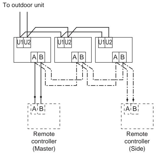
1-4-2 Two remote control
This control is that one or more indoor units are controlled by two remote controllers. (Max. two remote controller can be connected.)
One indoor unit operated by two remote controller
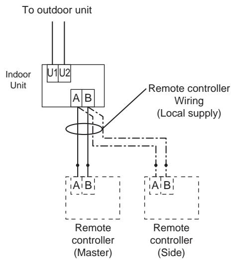
- Group control operated by two remote controller
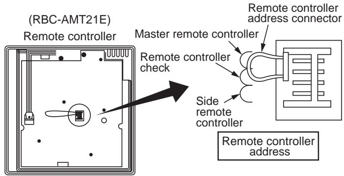
(Setting method for side remote controller)
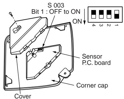
Change the remote controller address connector of the side remote controller on the P.C. board.
(In case of simple remote controller [RBC-AS21E], refer to "4-1-2 Simple remote controller")
Turn No.3 of DIP switch [S003] on sensor P.C. board from OFF to ON.
In case of 4-way cassette type (For others, refer to installation manual of wireless remote controller kit or "4-1-3 Wireless remote controller kit")
(Operation)
1) Operation mode can be changed by "last push priority".
2) In case of using a timer, connect the timer to either remote controller.
1-4-3 Group control
Max. 8 indoor units can be controlled by one remote controller on a group control.
Twin, triple control of 1 by 1 model (Toshiba Digital inverter, Super digital inverter) is one of group control.
Header indoor unit controls indoor air temperature based on setting temperature of the remote controller.
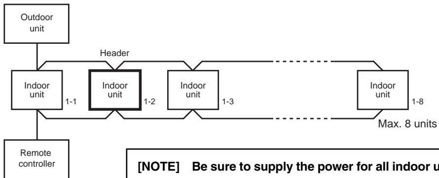
[NOTE] Be sure to supply the power for all indoor units on the group control. If the power isn't supplied to the header indoor unit, communication between indoor units and remote controller can't be performed.
[1] Display range of remote controller
Remote controller reflects the setting range of header indoor unit.
Setting range : Operation mode, Air Volume setting, Setting temperature
[NOTE] Don't set the concealed duct high pressure type (AID-P***H, MMD-P***1H) to the header indoor unit.
Set the other type indoor unit to the header indoor unit.
- In case concealed duct high static pressure type is the header indoor unit, display of remote controller is as follows.
Operation mode : [AUTO] [HEAT] [COOL] [FAN], no [DRY] mode
Air volume selection: [HIGH]
- In case of [DRY] mode, duct type keeps [FAN] mode.
[NOTE] Don't set cooling only model as header indoor unit.
Set heat pump model as header indoor unit.
- [AUTO] [HEAT] mode can't be operated.
[2] Remote location control (HA)
Both header and follower indoor unit can response by remote location control (HA) signals.
Master ON/OFF control can be conducted for all indoor units on the same group.
[NOTE] Don't input two or more HA signals to one group.
[3] Address setting
All indoor units on the same group must be turned on when automatic address setting is conducted.
If power supply is turned on three minutes later than automatic address setting, reboot will occur and automatic address setting starts again.
[NOTE.1] Be sure to do electrical work and control wiring certainly.
[NOTE.2] Reconfirm the line / indoor / group address one by one.
Especially confirm the identical line address both outdoor and indoor side.
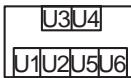
1-4-4 Application controls for central remote controller
| Basic function | System diagram | Model | Reference No. | |
| 1 | Central manage-ment controller for 64 units | U3, U4 Super MMS Outdoor unit Line-3 U1, U2 Super MMS Outdoor remote controller Line-2 U1, U2 Super MMS Outdoor remote controller Line-1 U1, U2 Super MMS Outdoor remote controller Line-2 U1, U2 Super MMS Outdoor remote controller Line-3 U1, U2 Super MMS Outdoor remote controller Line-4 U1, U2 Super MMS Outdoor remote controller Line-5 U1, U2 Super MMS Outdoor remote controller Line-6 U1, U2 Super MMS Outdoor remote controller Line-7 U1, U2 Super MMS Outdoor remote controller Line-8 U1, U2 Super MMS Outdoor remote controller Line-9 U1, U2 Super MMS Outdoor remote controller Line-10 U1, U2 Super MMS Outdoor remote controller Line-11 U1, U2 Super MMS Outdoor remote controller Line-12 U1, U2 Super MMS Outdoor remote controller Line-13 U1, U2 Super MMS Outdoor remote controller Line-14 U1, U2 Super MMS Outdoor remote controller Line-15 U1, U2 Super MMS Outdoor remote controller Line-16 U1, U2 Super MMS Outdoor remote controller Line-17 U1, U2 Super MMS Outdoor remote controller Line-18 U1, U2 Super MMS Outdoor remote controller Line-19 U1, U2 Super MMS Outdoor remote controller Line-20 U1, U2 Super MMS Outdoor remote controller Line-21 U1, U2 Super MMS Outdoor remote controller Line-22 U1, U2 Super MMS Outdoor remote controller Line-23 U1, U2 Super MMS Outdoor remote controller Line-24 U1, U2 Super MMS Outdoor remote controller Line-25 U1, U2 Super MMS Outdoor remote controller Line-26 U1, U2 Super MMS Outdoor remote controller Line-27 U1, U2 Super MMS Outdoor remote controller Line-28 U1, U2 Super MMS Outdoor remote controller Line-29 U1, U2 Super MMS Outdoor remote controller Line-30 U1, U2 Super MMS Outdoor remote controller Line-31 U1, U2 Super MMS Outdoor remote controller Line-32 U1, U2 Super MMS Outdoor remote controller Line-33 U1, U2 Super MMS Outdoor remote controller Line-34 U1, U2 Super MMS Outdoor remote controller Line-35 U1, U2 Super MMS Outdoor remote controller Line-36 U1, U2 Super MMS Outdoor remote controller Line-37 U1, U2 Super MMS Outdoor remote controller Line-38 U1, U2 Super MMS Outdoor remote controller Line-39 U1, U2 Super MMS Outdoor remote controller Line-40 U1, U2 Super MMS Outdoor remote controller Line-41 U1, U2 Super MMS Outdoor remote controller Line-42 U1, U2 Super MMS Outdoor remote controller Line-43 U1, U2 Super MMS Outdoor remote controller Line-44 U1, U2 Super MMS Outdoor remote controller Line-45 U1, U2 Super MMS Outdoor remote controller Line-46 U1, U2 Super MMS Outdoor remote controller Line-47 U1, U2 Super MMS Outdoor remote controller Line-48 U1, U2 Super MMS Outdoor remote controller Line-49 U1, U2 Super MMS Outdoor remote controller Line-50 U1, U2 Super MMS Outdoor remote controller Line-51 U1, U2 Super MMS Outdoor remote controller Line-52 U1, U2 Super MMS Outdoor remote controller Line-53 U1, U2 Super MMS Outdoor remote controller Line-54 U1, U2 Super MMS Outdoor remote controller Line-55 U1, U2 Super MMS Outdoor remote controller Line-56 U1, U2 Super MMS Outdoor remote controller Line-57 U1, U2 Super MMS Outdoor remote controller Line-58 U1, U2 Super MMS Outdoor remote controller Line-59 U1, U2 Super MMS Outdoor remote controller Line-60 U1, U2 Super MMS Outdoor remote controller Line-61 U1, U2 Super MMS Outdoor remote controller Line-62 U1, U2 Super MMS Outdoor remote controller Line-63 U1, U2 Super MMS Outdoor remote controller Line-64 U1, U2 Super MMS Outdoor remote controller Line-65 U1, U2 Super MMS Outdoor remote controller Line-66 U1, U2 Super MMS Outdoor remote controller Line-67 U1, U2 Super MMS Outdoor remote controller Line-68 U1, U2 Super MMS Outdoor remote controller Line-69 U1, U2 Super MMS Outdoor remote controller Line-70 U1, U2 Super MMS Outdoor remote controller Line-71 U1, U2 Super MMS Outdoor remote controller Line-72 U1, U2 Super MMS Outdoor remote controller Line-73 U1, U2 Super MMS Outdoor remote controller Line-74 U1, U2 Super MMS Outdoor remote controller Line-75 U1, U2 Super MMS Outdoor remote controller Line-76 U1, U2 Super MMS Outdoor remote controller Line-77 U1, U2 Super MMS Outdoor remote controller Line-78 U1, U2 Super MMS Outdoor remote controller Line-79 U1, U2 Super MMS Outdoor remote controller Line-80 U1, U2 Super MMS Outdoor remote controller Line-81 U1, U2 Super MMS Outdoor remote controller Line-82 U1, U2 Super MMS Outdoor remote controller Line-83 U1, U2 Super MMS Outdoor remote controller Line-84 U1, U2 Super MMS Outdoor remote controller Line-85 U1, U2 Super MMS Outdoor remote controller Line-86 U1, U2 Super MMS Outdoor remote controller Line-87 U1, U2 Super MMS Outdoor remote controller Line-88 U1, U2 Super MMS Outdoor remote controller Line-89 U1, U2 Super MMS Outdoor remote controller Line-90 U1, U2 Super MMS Outdoor remote controller Line-91 U1, U2 Super MMS Outdoor remote controller Line-92 U1, U2 Super MMS Outdoor remote controller Line-93 U1, U2 Super MMS Outdoor remote controller Line-94 U1, U2 Super MMS Outdoor remote controller Line-95 U1, U2 Super MMS Outdoor remote controller Line-96 U1, U2 Super MMS Outdoor remote controller Line-97 U1, U2 Super MMS Outdoor remote controller Line-98 U1, U2 Super MMS Outdoor remote controller Line-99 U1, U2 Super MMS Outdoor remote controller Line-100 U1, U2 Super MMS Outdoor remote controller Line-101 U1, U2 Super MMS Outdoor remote controller Line-102 U1, U2 Super MMS Outdoor remote controller Line-103 U1, U2 Super MMS Outdoor remote controller Line-104 U1, U2 Super MMS Outdoor remote controller Line-105 U1, U2 Super MMS Outdoor remote controller Line-106 U1, U2 Super MMS Outdoor remote controller Line-107 U1, U2 Super MMS Outdoor remote controller Line-108 U1, U2 Super MMS Outdoor remote controller Line-109 U1, U2 Super MMS Outdoor remote controller Line-110 U1, U2 Super MMS Outdoor remote controller Line-111 U1, U2 Super MMS Outdoor remote controller Line-112 U1, U2 Super MMS Outdoor remote controller Line-113 U1, U2 Super MMS Outdoor remote controller Line-114 U1, U2 Super MMS Outdoor remote controller Line-115 U1, U2 Super MMS Outdoor remote controller Line-116 U1, U2 Super MMS Outdoor remote controller Line-117 U1, U2 Super MMS Outdoor remote controller Line-118 U1, U2 Super MMS Outdoor remote controller Line-119 U1, U2 Super MMS Outdoor remote controller Line-120 U1, U2 Super MMS Outdoor remote controller Line-121 U1, U2 Super MMS Outdoor remote controller Line-122 U1, U2 Super MMS Outdoor remote controller Line-123 U1, U2 Super MMS Outdoor remote controller Line-124 U1, U2 Super MMS Outdoor remote controller Line-125 U1, U2 Super MMS Outdoor remote controller Line-126 U1, U2 Super MMS Outdoor remote controller Line-127 U1, U2 Super MMS Outdoor remote controller Line-128 U1, U2 Super MMS Outdoor remote controller Line-129 U1, U2 Super MMS Outdoor remote controller Line-130 U1, U2 Super MMS Outdoor remote controller Line-131 U1, U2 Super MMS Outdoor remote controller Line-132 U1, U2 Super MMS Outdoor remote controller Line-133 U1, U2 Super MMS Outdoor remote controller Line-134 U1, U2 Super MMS Outdoor remote controller Line-135 U1, U2 Super MMS Outdoor remote controller Line-136 U1, U2 Super MMS Outdoor remote controller Line-137 U1, U2 Super MMS Outdoor remote controller Line-138 U1, U2 Super MMS Outdoor remote controller Line-139 U1, U2 Super MMS Outdoor remote controller Line-140 U1, U2 Super MMS Outdoor remote controller Line-141 U1, U2 Super MMS Outdoor remote controller Line-142 U1, U2 Super MMS Outdoor remote controller Line-143 U1, U2 Super MMS Outdoor remote controller Line-144 U1, U2 Super MMS Outdoor remote controller Line-145 U1, U2 Super MMS Outdoor remote controller Line-146 U1, U2 Super MMS Outdoor remote controller Line-147 U1, U2 Super MMS Outdoor remote controller Line-148 U1, U2 Super MMS Outdoor remote controller Line-149 U1, U2 Super MMS Outdoor remote controller Line-150 U1, U2 Super MMS Outdoor remote controller Line-151 U1, U2 Super MMS Outdoor remote controller Line-152 U1, U2 Super MMS Outdoor remote controller Line-153 U1, U2 Super MMS Outdoor remote controller Line-154 U1, U2 Super MMS Outdoor remote controller Line-155 U1, U2 Super MMS Outdoor remote controller Line-156 U1, U2 Super MMS Outdoor remote controller Line-157 U1, U2 Super MMS Outdoor remote controller Line-158 U1, U2 Super MMS Outdoor remote controller Line-159 U1, U2 Super MMS Outdoor remote controller Line-160 U1, U2 Super MMS Outdoor remote controller Line-161 U1, U2 Super MMS Outdoor remote controller Line-162 U1, U2 Super MMS Outdoor remote controller Line-163 U1, U2 Super MMS Outdoor remote controller Line-164 U1, U2 Super MMS Outdoor remote controller Line-165 U1, U2 Super MMS Outdoor remote controller Line-166 U1, U2 Super MMS Outdoor remote controller Line-167 U1, U2 Super MMS Outdoor remote controller Line-168 U1, U2 Super MMS Outdoor remote controller Line-169 U1, U2 Super MMS Outdoor remote controller Line-170 U1, U2 Super MMS Outdoor remote controller Line-171 U1, U2 Super MMS Outdoor remote controller Line-172 U1, U2 Super MMS Outdoor remote controller Line-173 U1, U2 Super MMS Outdoor remote controller Line-174 U1, U2 Super MMS Outdoor remote controller Line-175 U1, U2 Super MMS Outdoor remote controller Line-176 U1, U2 Super MMS Outdoor remote controller Line-177 U1, U2 Super MMS Outdoor remote controller Line-178 U1, U2 Super MMS Outdoor remote controller Line-179 U1, U2 Super MMS Outdoor remote controller Line-180 U1, U2 Super MMS Outdoor remote controller Line-181 U1, U2 Super MMS Outdoor remote controller Line-182 U1, U2 Super MMS Outdoor remote controller Line-183 U1, U2 Super MMS Outdoor remote controller Line-184 U1, U2 Super MMS Outdoor remote controller Line-185 U1, U2 Super MMS Outdoor remote controller Line-186 U1, U2 Super MMS Outdoor remote controller Line-187 U1, U2 Super MMS Outdoor remote controller Line-188 U1, U2 Super MMS Outdoor remote controller Line-189 U1, U2 Super MMS Outdoor remote controller Line-190 U1, U2 Super MMS Outdoor remote controller Line-191 U1, U2 Super MMS Outdoor remote controller Line-192 U1, U2 Super MMS Outdoor remote controller Line-193 U1, U2 Super MMS Outdoor remote controller Line-194 U1, U2 Super MMS Outdoor remote controller Line-195 U1, U2 Super MMS Outdoor remote controller Line-196 U1, U2 Super MMS Outdoor remote controller Line-197 U1, U2 Super MMS Outdoor remote controller Line-198 U1, U2 Super MMS Outdoor remote controller Line-199 U1, U2 Super MMS Outdoor remote controller Line-200 U1, U2 Super MMS Outdoor remote controller Line-201 U1, U2 Super MMS Outdoor remote controller Line-202 U1, U2 Super MMS Outdoor remote controller Line-203 U1, U2 Super MMS Outdoor remote controller Line-204 U1, U2 Super MMS Outdoor remote controller Line-205 U1, U2 Super MMS Outdoor remote controller Line-206 U1, U2 Super MMS Outdoor remote controller Line-207 U1, U2 Super MMS Outdoor remote controller Line-208 U1, U2 Super MMS Outdoor remote controller Line-209 U1, U2 Super MMS Outdoor remote controller Line-210 U1, U2 Super MMS Outdoor remote controller Line-211 U1, U2 Super MMS Outdoor remote controller Line-212 U1, U2 Super MMS Outdoor remote controller Line-213 U1, U2 Super MMS Outdoor remote controller Line-214 U1, U2 Super MMS Outdoor remote controller Line-215 U1, U2 Super MMS Outdoor remote controller Line-216 U1, U2 Super MMS Outdoor remote controller Line-217 U1, U2 Super MMS Outdoor remote controller Line-218 U1, U2 Super MMS Outdoor remote controller Line-219 U1, U2 Super MMS Outdoor remote controller Line-220 U1, U2 Super MMS Outdoor remote controller Line-221 U1, U2 Super MMS Outdoor remote controller Line-222 U1, U2 Super MMS Outdoor remote controller Line-223 U1, U2 Super MMS Outdoor remote controller Line-224 U1, U2 Super MMS Outdoor remote controller Line-225 U1, U2 Super MMS Outdoor remote controller Line-226 U1, U2 Super MMS Outdoor remote controller Line-227 U1, U2 Super MMS Outdoor remote controller Line-228 U1, U2 Super MMS Outdoor remote controller Line-229 U1, U2 Super MMS Outdoor remote controller Line-230 U1, U2 Super MMS Outdoor remote controller Line-231 U1, U2 Super MMS Outdoor remote controller Line-232 U1, U2 Super MMS Outdoor remote controller Line-233 U1, U2 Super MMS Outdoor remote controller Line-234 U1, U2 Super MMS Outdoor remote controller Line-235 U1, U2 Super MMS Outdoor remote controller Line-236 U1, U2 Super MMS Outdoor remote controller Line-237 U1, U2 Super MMS Outdoor remote controller Line-238 U1, U2 Super MMS Outdoor remote controller Line-239 U1, U2 Super MMS Outdoor remote controller Line-240 U1, U2 Super MMS Outdoor remote controller Line-241 U1, U2 Super MMS Outdoor remote controller Line-242 U1, U2 Super MMS Outdoor remote controller Line-243 U1, U2 Super MMS Outdoor remote controller Line-244 U1, U2 Super MMS Outdoor remote controller Line-245 U1, U2 Super MMS Outdoor remote controller Line-246 U1, U2 Super MMS Outdoor remote controller Line-247 U1, U2 Super MMS Outdoor remote controller Line-248 U1, U2 Super MMS Outdoor remote controller Line-249 U1, U2 Super MMS Outdoor remote controller Line-250 U1, U2 Super MMS Outdoor remote controller Line-251 U1, U2 Super MMS Outdoor remote controller Line-252 U1, U2 Super MMS Outdoor remote controller Line-253 U1, U2 Super MMS Outdoor remote controller Line-254 U1, U2 Super MMS Outdoor remote controller Line-255 U1, U2 Super MMS Outdoor remote controller Line-256 U1, U2 Super MMS Outdoor remote controller Line-257 U1, U2 Super MMS Outdoor remote controller Line-258 U1, U2 Super MMS Outdoor remote controller Line-259 U1, U2 Super MMS Outdoor remote controller Line-260 U1, U2 Super MMS Outdoor remote controller Line-261 U1, U2 Super MMS Outdoor remote controller Line-262 U1, U2 Super MMS Outdoor remote controller Line-263 U1, U2 Super MMS Outdoor remote controller Line-264 U1, U2 Super MMS Outdoor remote controller Line-265 U1, U2 Super MMS Outdoor remote controller Line-266 U1, U2 Super MMS Outdoor remote controller Line-267 U1, U2 Super MMS Outdoor remote controller Line-268 U1, U2 Super MMS Outdoor remote controller Line-269 U1, U2 Super MMS Outdoor remote controller Line-270 U1, U2 Super MMS Outdoor remote controller Line-271 U1, U2 Super MMS Outdoor remote controller Line-272 U1, U2 Super MMS Outdoor remote controller Line-273 U1, U2 Super MMS Outdoor remote controller Line-274 U1, U2 Super MMS Outdoor remote controller Line-275 U1, U2 Super MMS Outdoor remote controller Line-276 U1, U2 Super MMS Outdoor remote controller Line-277 U1, U2 Super MMS Outdoor remote controller Line-278 U1, U2 Super MMS Outdoor remote controller Line-279 U1, U2 Super MMS Outdoor remote controller Line-280 U1, U2 Super MMS Outdoor remote controller Line-281 U1, U2 Super MMS Outdoor remote controller Line-282 U1, U2 Super MMS Outdoor remote controller Line-283 U1, U2 Super MMS Outdoor remote controller Line-284 U1, U2 Super MMS Outdoor remote controller Line-285 U1, U2 Super MMS Outdoor remote controller Line-286 U1, U2 Super MMS Outdoor remote controller Line-287 U1, U2 Super MMS Outdoor remote controller Line-288 U1, U2 Super MMS Outdoor remote controller Line-289 U1, U2 Super MMS Outdoor remote controller Line-290 U1, U2 Super MMS Outdoor remote controller Line-291 U1, U2 Super MMS Outdoor remote controller Line-292 U1, U2 Super MMS Outdoor remote controller Line-293 U1, U2 Super MMS Outdoor remote controller Line-294 U1, U2 Super MMS Outdoor remote controller Line-295 U1, U2 Super MMS Outdoor remote controller Line-296 U1, U2 Super MMS Outdoor remote controller Line-297 U1, U2 Super MMS Outdoor remote controller Line-298 U1, U2 Super MMS Outdoor remote controller Line-300 U1, U2 Super MMS Outdoor remote controller Line-301 U1, U2 Super MMS Outdoor remote controller | ||
| 3 | Remote central control without indoor remote controller | U3, U4 Power supply Single phase 220/230/240V Example of grouping operation U3, U4 Power supply Single phase 220/230/240V Power supply Single phase 220/230/240V U3, U4 Power supply Single phase 220/230/240V Power supply Single phase 220/230/240V * TOSHIBA Digital Inverter System and Super Digital Inverter System | ·Central remote controller TCB-SC642TLE ·Indoor remote controller ·Wired remote controller RBC-AMT21E | 4-2 |
| 4 | Central management with "1:1 model" | Power supply U3, U4 Header unit Super MMS *1 *1 *1 *1 *1 *1 *1 *1 *1 *1 *1 *1 *1 *1 *1 *1 *1 *1 *1 *1 *1 *1 *1 *1 *1 *1 *1 *1 *1 *1 *1 *1 *1 *1 | ·Central remote controller TCB-SC642TLE ·"1:1 model" connection interface TCB-PCNT30TLE (RAV-SM560KRT-E, SM800KRT-E are not available) | 4-2 |
1-5 Application controls of indoor unit
| No | Control name | Function | Reference No. | |
| 1 | Function change | Items necessary to perform the applied control at the local site can be selected. (Ex. Setup of TA sensor, body TA sensor / remote controller sensor) | Item code (DN) setting from wired remote controller | 4-3-1 |
| 2 | Ventilation fan control from remote controller | ON/OFF control can be operated from wired remote controller when the entire heat exchanger or ventilation fan is installed in the system. Relay (DC12V, procured locally) CN32 FAN DRIVE (2P WHI) Indoor control P.C board | Setting from wired remote controller + Relay wiring (local supply) | 4-3-2 |
| 3 | Leaving-ON prevention control | Using a card switch box, card lock etc, the leaving-ON of the indoor unit can be prevented by setting of remote controller and relay wiring. CN61 T10 (YEL) Indoor control P.C board | Setting from wired remote controller + Relay wiring (local supply) | 4-3-3 |
| 4 | Demand control | Thermostat-OFF operation by relay signal. •Wiring example CN73 1 1 2 2 EXCT (2P plug: RED) Indoor control P.C board | Relay wiring (local supply) | 4-3-4 |
| 5 | Remote sensor (TCB-TC21LE) | Air temperature sensing at a distance. Remote sensor (Sold separately) Terminal block for remote controller cable Earth [A B] Indoor unit [NOTE] Don't change TA sensor to remote controller sensor by item code (DN) setting. | Remote sensor (TCB-TC21LE) | 4-3-5 |
1-6 Application controls of outdoor unit
| No | Control name | Function | Setting method | Reference No. |
| 1 | Outdoor fan high static pressure shift | Increase outdoor fan speed so that a duct with the maximum outside static pressure 35Pa can be installed. | Switch setting on outdoor interface P.C. board | 4-4-1 |
| 2 | Cooling priority, heating priority control | Cooling priority or heating priority can be selected. (Setup at shipment: heating priority) | 4-4-2 | |
| 3 | Specific indoor unit priority control | Only one indoor unit can be set to priority for changeover operation mode. | Switch setting on outdoor interface P.C. board + Item code (DN) setting from wired remote controller | 4-4-3 |
1-7 Application controls by optional P.C. board of outdoor unit
| Model name | Appearance | Function | Reference No. | |||
| TCB-PCDM2E | Size:71x85(mm) | [1] Power peak-cut Control ●Feature The upper limit capacity of the outdoor unit is restricted based on the power peak cut request signal from outside. ●Function Two type control can be selected by setting SW07 on the interface P.C. board of the header outdoor unit. | 4-5-1 | |||
| TCB-PCDM2E ON COM OFF COM | Local Supply SW1 SW2 | |||||
| Application | [Standard function] SW07-2 OFF | |||||
| Input | SW07-1 | |||||
| SW01 | SW02 | OFF | ON | |||
| ON | OFF | 0% (stop) | Up to 60% | |||
| OFF | ON | 100% (Normal) | 100% (Normal) | |||
| *Place this optional P.C. board to inverter assembly of the header outdoor unit. | [Expansion function] SW07-2 ON | |||||
| Input | SW07-1 | |||||
| SW01 | SW02 | OFF | ON | |||
| OFF | OFF | 100% (Normal) | 100% (Normal) | |||
| ON | OFF | Up to 80% | Up to 85% | |||
| OFF | ON | Up to 60% | Up to 75% | |||
| ON | ON | 0% (stop) | Up to 60% | |||
| ●Be sure to prepare the point of contact for each terminal. ●Don't turn on both SW1 and SW2 terminal simultaneously. | ||||||
| Model name | Appearance | Function | Reference No. | |||
| TCB-PCMO2E | Size:55.5x60(mm) | [2] Snowfall fan control ●Feature Outdoor fan is operated with the snowfall signal from outside. ●Function TCB-PCMO2E COM Cooling Local Supply SMC | 4-5-2 | |||
| Application | Terminal | Input signal | Operation | |||
| SMC | ON OFF | Snowfall fan control (Operates outdoor fan.) | ||||
| ON OFF | Usual operation (Releases control) | |||||
| This control is conducted when input signal stand up and fall down. (Standing and falling status should be held for 100 mm.sec. or more.) | ||||||
| *Place this optional P.C. board to inverter assembly of the header outdoor unit. | [3] External master ON/OFF control ●Feature The outdoor unit starts or stops the system. ●Function TCB-PCMO2E COM Cooling Heating Local Supply SMC : Input signal for start SMH : Input signal for stop | 4-5-3 | ||||
| Terminal | Input signal | Operation | ||||
| SMC | ON OFF | Starts all indoor units. | ||||
| SMH | ON OFF | Stops all indoor units. | ||||
| ●Be sure to prepare non voltage continuous point of contact for each terminal. This control is conducted when input signal stand up or fall down. (Standing and falling status should be held for 100 mm.sec. or more.) | ||||||
| TCB-PCMO2E | Size:55.5x60(mm) | [4] Night operation (Sound reduction) control ●Feature Sound level can be reduced with connecting outdoor E-parts by restricting compressor and fan speed. ●Function TCB-PCMO2E COM Cooling Local Supply SMC | 4-5-4 | |||
| Application | ||||||
| *Place this optional P.C. board to inverter assembly of the header outdoor unit. | Terminal | Input signal | Operation | |||
| SMC | ON OFF | Night operation (sound reduction) control | ||||
| ON OFF | Usual Operation | |||||
| This control is conducted when input signal stand up or fall down. (Standing and falling status should be held for 100 mm.sec or more.) | ||||||
| [5] Operation mode selection control ●Feature This control can be operated with the operation mode which is permitted by SMC or SMH. ●Function TCB-PCMO1E COM Cooling Heating Local Supply SMC SMH | 4-5-5 | |||||
| SMC:Cooling mode designated input switch SMH:Heating mode designated input switch | ||||||
| SMC | SMH | Selected operation mode | ||||
| ON | OFF | Only cooling mode permitted | ||||
| OFF | ON | Only heating mode permitted | ||||
| Be sure to prepare non-voltage continuous point of contact for each terminal. | ||||||
1-8 Application controls by optional devices connected to indoor unit
[1] Remote location ON/OFF control box
| Model name | Appearance | Features | Reference No. |
| TCB-ICCB-4E | ● Start and stop of air conditioner is possible by the external signal, and also indication of operation/ alarm to outside is possible. | 4-6-1 | |
| Application | Function | ||
| Operation Display Remote Controller | ● Monitoring ON/OFF status (for indoor unit) Alarm status (system & indoor unit stop) ● ON/OFF command Air conditioner can be turned ON/OFF by the external signals. The external ON/OFF signals are output for the signals below. ON/OFF COM Non-voltage ON /OFF continuous signal |
[2] Network adapter
| Model name | Appearance | Features | Reference No. |
| TCB-PCNT20E | Place optional P.C. board in E-parts of indoor unit. | ● Indoor units of VRF system is controlled by AI-Network central remote controllerConnectable indoor units per group. | 4-6-2 |
| Connection of cables | |||
| Central remote controllerNon polarity cableCN0312131415161718191011121314151617181910112131415161718191011213141516171819101121314151617181910112131415161718191011213141516171819101121 | |||
| Application | Non polarity cableRemote controller | ||
| Power Supply Central Remote Controller TCB-SC641E Network Adapter Indoor unit Remote Controller | Wiring diagram of indoor P.C. board | ||
| Network connection terminal block |
[3] “1:1 model” connection interface
| Model name | Appearance | Features | Reference No. | |
| TCB-PCNT30TLE | Place optional P.C. board in E-parts of indoor unit. | ● Link adapter for "1:1 model" into VRF system network 1:1 model : Super digital inverter Digital inverter | 4-6-3 | |
| Connection of cables | ||||
| Central control devices U3U4 Adaptor Indoor control PC board A B Remote controller | 4-6-3 | |||
| Application | ||||
| 1:1 model connection interface Super MMS control wiring Digital Inverter Super Digital Inverter | Wiring diagram of indoor P.C. board | |||
| CN40 (BIU) CN51 (RED) adapter 1 1 2 2 3 3 4 4 5 5 CN50 (WHI) Indoor control P.C. board 1 1 2 2 3 3 4 4 5 5 6 6 7 7 8 8 9 9 10 10 11 11 12 12 13 13 14 14 15 15 16 16 17 17 18 18 19 19 20 20 21 21 22 22 23 23 24 24 25 25 26 26 27 27 28 28 29 29 30 30 31 31 32 32 33 33 34 34 35 35 36 36 37 37 38 38 39 39 40 40 41 41 42 42 43 43 44 44 45 45 46 46 47 47 48 48 49 49 50 50 51 51 52 52 53 53 54 54 55 55 56 56 57 57 58 58 59 59 60 60 61 61 62 62 63 63 64 64 65 65 66 66 67 67 68 68 69 69 70 70 71 71 72 72 73 73 74 74 75 75 76 76 77 77 78 78 79 79 80 80 81 81 82 82 83 83 84 84 85 85 86 86 87 87 88 88 89 89 90 90 91 91 92 92 93 93 94 94 95 95 96 96 97 97 98 98 99 99 | CN50 (WHI) Indoor control P.C. board 11 11 12 22 13 23 14 24 15 25 16 26 17 27 18 28 19 29 20 30 21 31 22 32 23 33 24 34 25 35 26 36 27 37 28 38 29 39 30 40 31 41 32 42 33 43 34 44 35 45 36 46 37 47 38 48 39 49 40 50 41 51 42 52 43 53 44 54 45 55 46 56 47 57 48 58 49 59 50 60 51 61 52 62 53 63 54 64 55 65 56 66 57 67 58 68 59 69 60 70 61 71 62 72 63 73 64 74 65 75 66 76 67 77 68 78 69 79 70 80 71 81 72 82 73 83 74 84 75 85 76 86 77 87 78 88 79 89 80 90 81 91 82 92 83 93 84 94 85 95 86 96 87 97 88 98 89 99 |
1-9 Application control for network (Tentative)
1-9-1 Touch screen controller system
| System Diagram | Reference No. | |||
| Intelligent Server Software Ethernet connection RS-485 Control wiring Intelligent Server TCS-Net Relay Interface Control Maximum 512 FCU Maximum 4 Intelligent server Maximum 8 Relay Interface Maximum 4 Energy Monitoring Relay Interface I/F RS-485 Local supply 1 pulse/ kWh 200-400 ms Energy Meter Relay Interface Maximum 8 Power Meter Maximum 3 Input & 1 Output More I/O Fire alarm Door Key Entry ON/OFF Error code output Digital I/O Relay Interface | 4-6-3 | |||
| Devices | Model Name | Model Name | Specification | |
| Touch Screen controller (English version) | BMS-TP0640ACE | Max 64 FCU, without electrical bill calculation | ||
| BMS-TP5120ACE | Max 512 FCU, without electrical bill calculation | |||
| BMS-TP0640PWE | Max 64 FCU, with electrical bill calculation | |||
| BMS-TP5120PWE | Max 512 FCU, with electrical bill calculation | |||
| Intelligent Server | BMS-LSV2E | Server in between Screen controller & control wiring | ||
| Intelligent Server Software | BMS-STCC01E | Installed to Intelligent Server | ||
| TCS-Net Relay Interface | BMS-IFLSV1E | I/F in between Intelligent server & control wiring | ||
| Energy Monitoring Relay Interface | BMS-IFWH3E | I/F for Power Meter | ||
| Digital I/O Relay Interface | BMS-IFDD01E | I/F for I/O signal | ||
| Function | (1) Monitoring air-conditioners | Operation status can be seen according to a unit. 【Unit】All building, All tenants, Each tenant, Each area, Each air-conditioning system 【Monitoring contents】Operation and alarm status, Setting status for each air-conditioning system | ||
| (2) Operating of air-conditioners | Master / individual control can be performed according to a unit. 【Operating contents】ON/OFF, Operation setting (operation mode, air volume, frap position, setting temp., inhibited setting from remote location) | |||
| (3) Schedule operation | Air-conditioners are operated according to set-up schedule / operation pattern. Schedule operation can be performed according to a unit. 【Operation pattern】Weekly pattern, special day pattern (4 pattern), No-work days pattern | |||
| (4) Alarm list display | The present alarm contents are list-displayed. 【Display contents】Alarm contents, Unit number, Generated time | |||
| (5) Alarm record display | The past alarm records are list-displayed. 【Display contents】Alarm contents, Unit number, Generated time | |||
| (6) Monthly report data extraction | Monthly report data is written in "Compact Flash". Monthly report can be created according to a unit using monthly report software. 【Monthly report contents】The number of ON/OFF, Operating time, Results of energy monitoring | |||
| (7) Energy monitoring data extraction | Power consumption data is written in "Compact Flash". Energy monitoring can be performed according to a unit using energy monitoring software. 【Energy monitoring data】Power consumption according to the power meter | |||
1-9-2 LONWORKS
| System diagram | Model | Reference No. |
| LON Center LON Interfaces Super MMS Remote controller "1:1 model" connection interface *1 TOSHIBA Digital Inverter System and Super Digital Inverter System The LONWORKS interface shall be connected between a building management computer and the Super HRM and Super MMS system. [LONWORKS Gateway] ■ Command ·Operation : ON/OFF ·Mode : Cool/Heat/Fan ·Temperature setting ·Center/Local ■ Monitor ·Operation : ON/OFF ·Mode : Cool/Heat/Fan/failure ·Temperature setting ·Room temperature ·Center/Local | ·LON Gateway TCB-IFLN**** ·"1:1 model" connection interface TCB-PCNT30TLE (RAV-SM560KRT-E, SM800KRT-E are not available) <Indoor remote controller> ·Wired remote controller RBC-AMT21E or ·Simple remote controller RBC-AS21E | 4-7-2 |
1-9-3 Windows based central controller
| System diagram | Model | Reference No. | |
| Personal computer on site Local server Relay Interface Remote controller *1 TOSHIBA Digital Inverter System and Super Digital Inverter System The local server shall be “Plug-in” into a customer's personal computer. | ·WINDOWS based central controller BMS-LSV** ·TCS-Net Relay Interface BMS-IFLSV1E ·Intelligent server BMS-LSV2E BMS-STC01E ·Energy Monitoring Relay Interface BMS-IFWH3E ·Digital I/O Relay Interface BMS-IFDD01E ·“1:1 model” connection interface TCB-PCNT30TLE (RAV-SM560KRT-E, SM800KRT-E are not available) | 4-7-3 | |
| ·“1:1 model” connection interface TCB-PCNT30TLE (RAV-SM560KRT-E, SM800KRT-E are not available) | |||
| ·“1:1 model” connection interface TCB-PCNT30TLE (RAV-SM560KRT-E, SM800KRT-E are not available) | |||
| ·“1:1 model” connection interface TCB-PCNT30TLE (RAV-SM560KRT-E, SM800KRT-E are not available) | |||
| ·"1:1 model" connection interface TCB-PCNT30TLE (RAV-SM560KRT-E, SM800KRT-E are not available) | |||
| ·"1:1 model" connection interface TCB-PCNT30TLE (RAV-SM560KRT-E, SM800KRT-E are not available) | |||
| ·"1:1 model" connection interface TCB-PAC-TL (RAV-SM560KRT-E, SM800KRT-E are not available) | |||
| ·"1:1 model" connection interface TCB-PCNT30TLE (RAV-SM560KRT-E, SM800KRT-E are not available) | |||
| ·"1:1 model" connection interface TCB-PCNT30TLE (RAV-SM800KRT-E, SM800KRT-E are not available) | |||
| ·"1:1 model" connection interface TCB-PCNT30TLE (RAV-SM800KRT-E, SM800KRT-E are not available) | |||
| ·"1:1 model" connection interface TCB-PCNT30TLE (RAV-SM800KRT-E,SM800KRT-E are not available) | |||
| ·"1:1 model" connection interface TCB-PCNT30TLE (RAV-SM800KRT-E,SM800KRT-E are not available) | |||
| ·"1:1 model" connection interface TCB-PCNT30TLE (RAV-SM800KRT-E,SM800KRT-I are not available) | |||
| ·"1:1 model" connection interface TCB-PCNT30TLE (RAV-SM800KRT-E,SM800KRT-I are not available) | |||
| ·"1:1 model" connection interface TCB-PCNT30TLE (RAV-SM800KRT-E,SM800KRT-I are not available) |
1-9-4 BACnet
| System diagram | Model | Reference No. |
| BAC net center Local server TCS-Net Relay Interface Remote controller *1 TOSHIBA Digital Inverter System and Super Digital Inverter System The local server shall be connected under the BACnet network, and shall be connected the Super HRM and Super MMS system through the interface. | ·BACnet local server BMS-LSV********** ·TCS-Net Relay Interface BMS-IFLSV1E ·"1:1 model" connection interface TCB-PCNT30TLE (RAV-SM560KRT-E, SM800KRT-E are not available) <Indoor remote controller> ·Wired remote controller RBC-AMT21E ·Simple remote controller RBC-AS21E | 4-7-4 |
(Note) For "1-9-1" to "1-9-4", details of specification were not available at the time of publication. For further information (set up, adjustment), consult the sales subsidiary.
SYSTEM WIRING DIAGRAM AND
CONTROL WIRING METHOD
2-1 Applicable model and connectable units
2-2 System wiring diagram
2-2-1 For VRF system only
2-2-2 For combined system with "1:1model"
2-3 Design of control wiring
2-4 Earth method of shield wiring
2-4-1 For VRF system only
2-4-2 For combined system with "1:1model"
2-5 General requirement for control wiring
2-1 Applicable model and connectable units
1) Applicable model
- VRF system ......... Super modular multi system (Super MMS) Super heat recovery multi system (Super HRM
- 1:1 model Super digital inverter, Digital inverter
2) The number of connectable units
[1] For only VRF system
| Connected unit | No. of units | Note | |
| 1 | Outdoor unit (Header unit) | Up to 16 units | |
| 2 | Outdoor unit (Follower unit) | Up to 3 units | In the same refrigerant system |
| 3 | Indoor unit | Up to 64 units | • Max 64 units in case of group control* • Max. 48 units for one refrigerant system |
| 4 | Group control for indoor units | Up to 8 units | |
| 5 | Central control device | Up to 10 units | • Central remote controller |
- Follower indoor unit in a group control must be counted as one indoor unit.
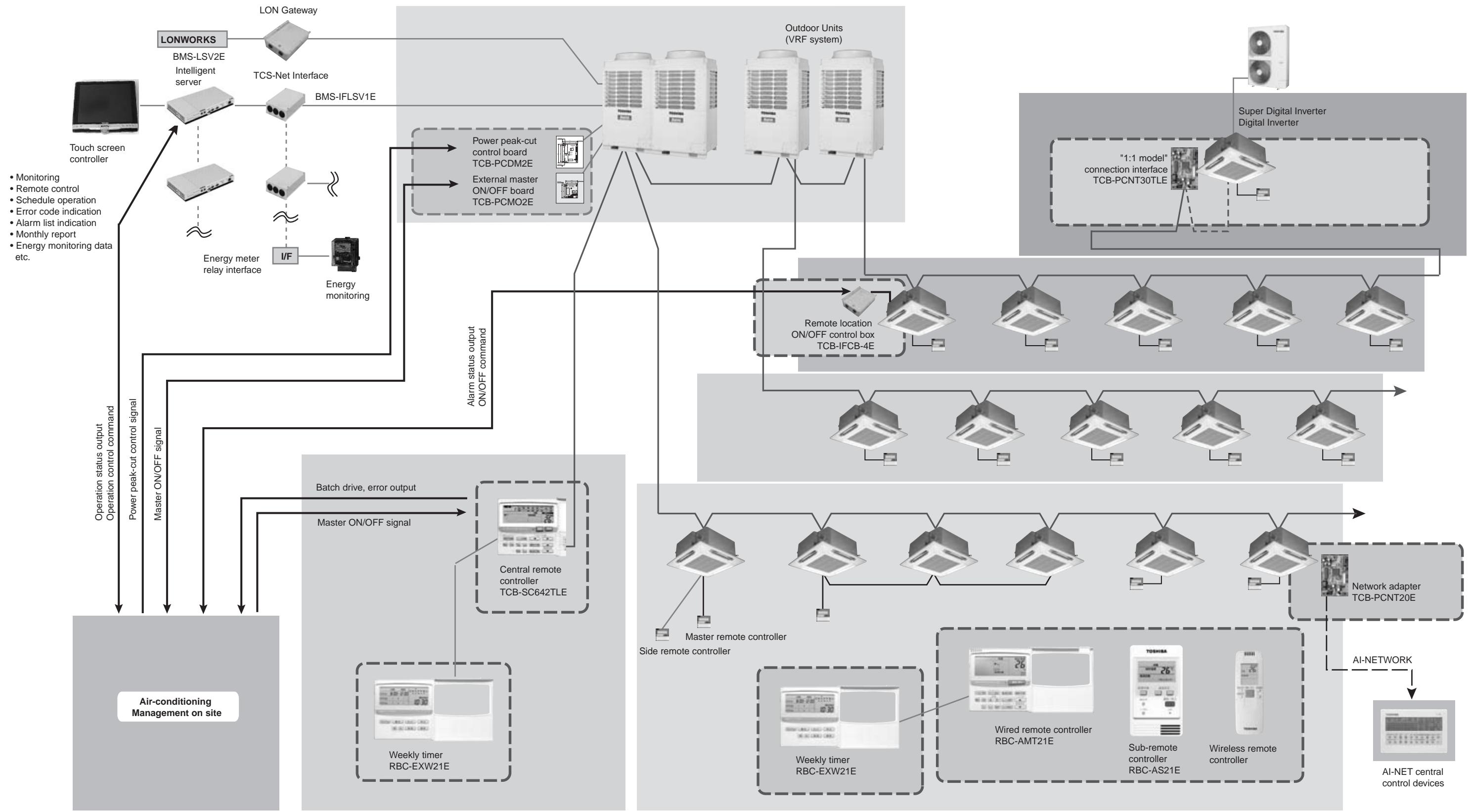
[2] For combined system with Digital Inverter / Super Digital Inverter
| Connected unit | No. of units | Note | |
| 1 | Outdoor unit (Header unit for VRF system) | Up to 16 units | |
| 2 | Outdoor unit (Follower unit for VRF system) | Up to 3 units | In the same refrigerant system |
| 3 | Indoor unit | Up to 64 units | • Max. 64 units for total number of indoor units for both system. * For 1:1 model, follower indoor units of twin control and group control must not be counted. * For VRF system, Max. 48 indoor units in one refrigerant system. |
| 4 | Group control for indoor units | Up to 8 units | |
| 5 | Central control device | Up to 10 units | • Central remote controller |
- Max. 64 refrigerant system can be controlled for total number of VRF system and 1:1 model.
(However, for VRF system, up to 16 refrigerant system can be connectable.) - "1:1 model" connection interface is connected to the indoor unit of 1:1 model.
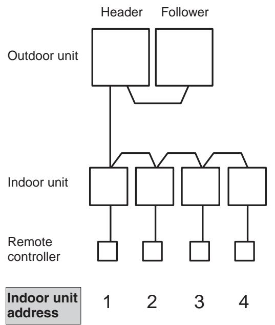
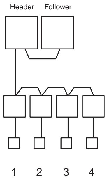
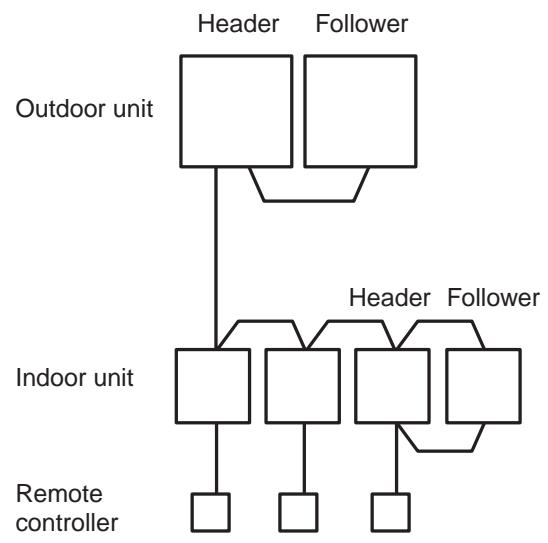
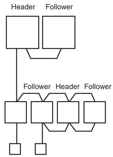
![TOSHIBA TCB-SC642TLE2 - [2] For combined system with Digital Inverter / Super Digital Inverter - 1](/content/2025/01/121691/images/5126d88bd89eab72f7a08143e12ee44d7a00bed75e7589af7144062f1b53b5e1.jpg)
![TOSHIBA TCB-SC642TLE2 - [2] For combined system with Digital Inverter / Super Digital Inverter - 2](/content/2025/01/121691/images/c42cd0997cb328b8b194a55a2c283e50f0cdb9259e688f21212c12a9d60531fd.jpg)
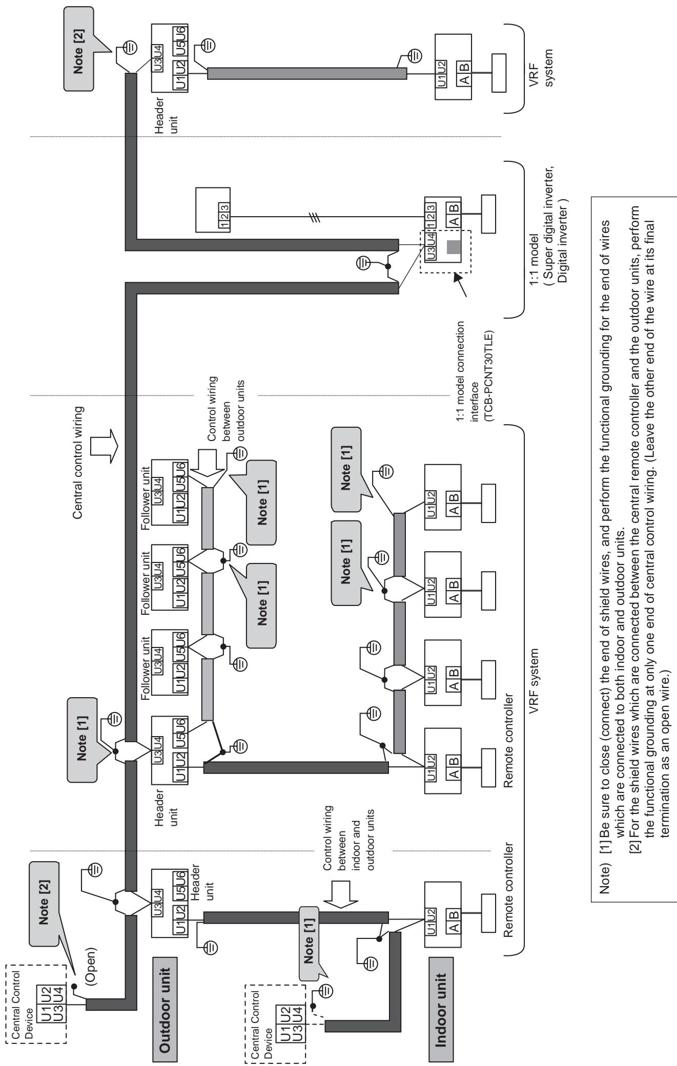
Max. 64 indoor units for all refrigerant systems (Don't count follower indoor units of group control and twin control of 1:1 model.)
Note) [1] Don't connect control wiring between indoor and outdoor units to several outdoor units.
(Outdoor unit to which control wiring between indoor and outdoor units is connected becomes the header outdoor unit
automatically.)
[2] Don't connect control wiring between indoor and outdoor units to other refrigerant system.
[3] Connect central control wiring to the header outdoor unit.
[4] When "1:1 model" is controlled by central control devices, "1:1 model" connection interface is necessary.
[5] In case of twin control on 1:1 model, connect "1:1 model"
[6] Connect central control devices to central control wiring.
[7] Central control devices can be also connected to control wiring between indoor and outdoor units.
2-3 Design of control wiring
-
All control wiring is 2-core and non-polarity wire.
-
Be sure to use shield wire for the following wiring to prevent noise trouble.
-
Outdoor-outdoor / indoor-indoor / outdoor-indoor control wiring, Central control wiring.
Control wiring between indoor and outdoor units (L1,L2,L3),
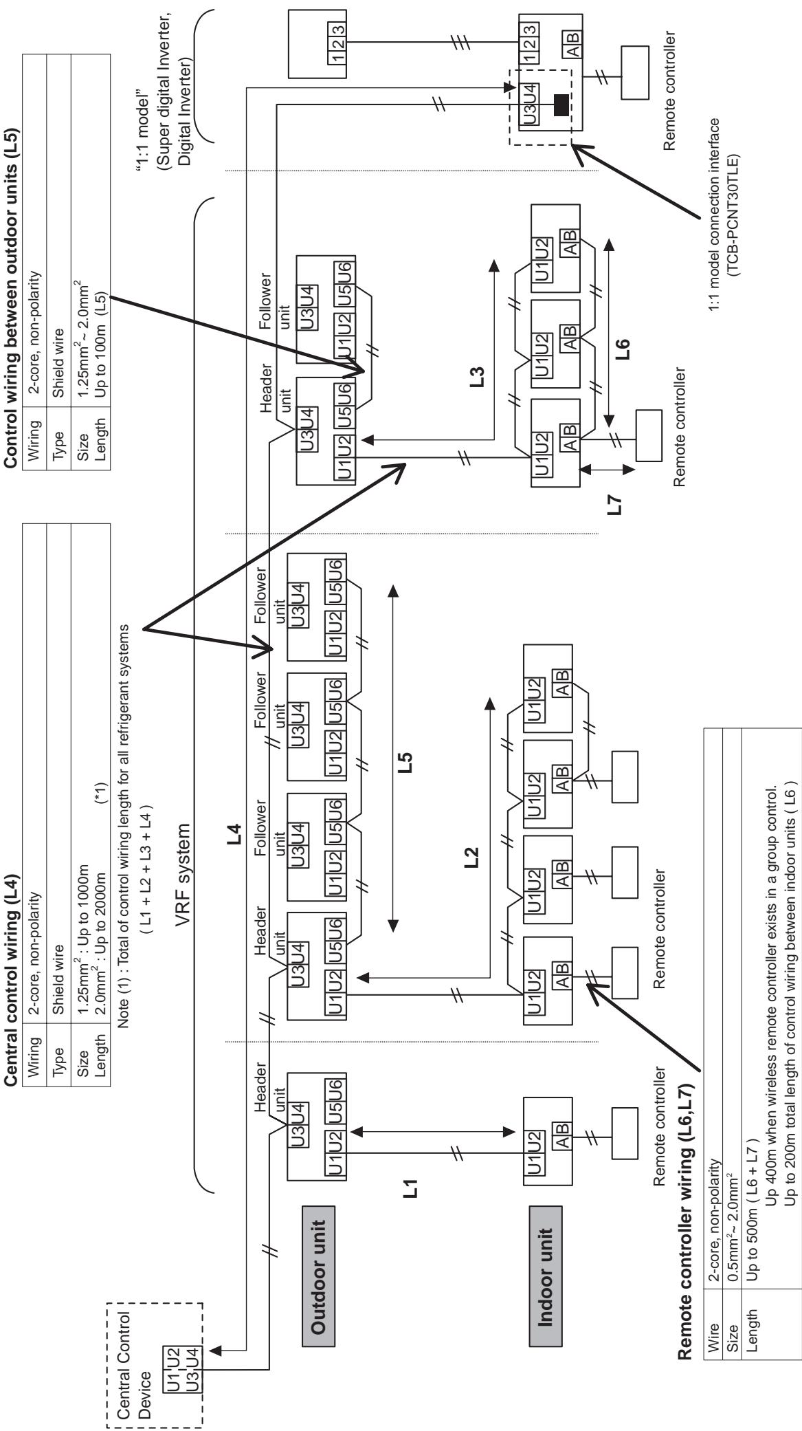
Note) [1] Be sure to close (connect) the end of shield wires, and perform the functional grounding for the end of wires
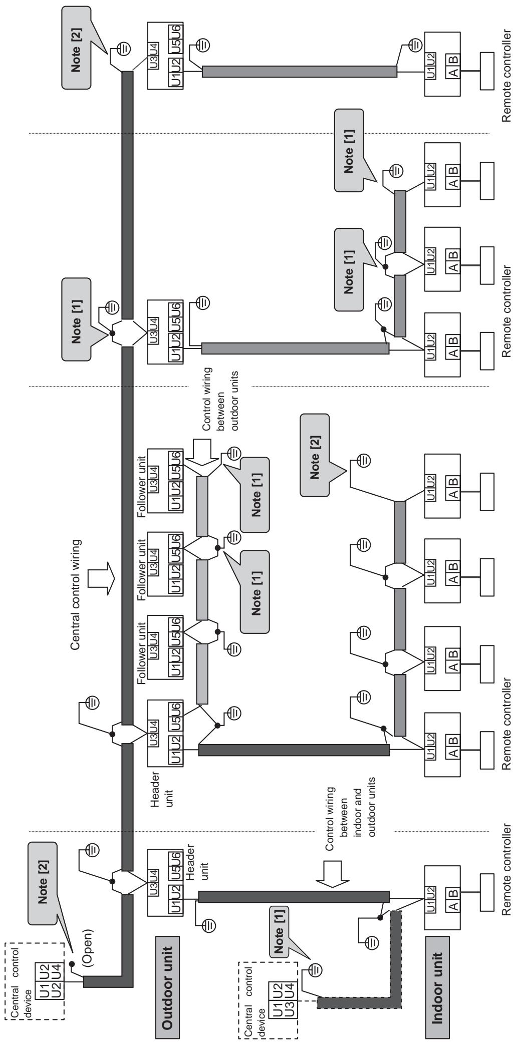
[2] For the shield wires which are connected between the central remote controller and the outdoor units, perform
the functional grounding at only one end of central control wiring. (Leave the other end of the wire at its final
termination as an open wire.)
2-4-2 For combined system with "1:1 model"
2-5 General requirement for control wiring
1) Separate control wiring from power source line to prevent malfunction.
2) 50mm or more must be needed from the power source line of air conditioner.
3) 300mm or more must be needed from other power source.
4) Be sure to perform the functional grounding for the end of the shield wires which are connected to both indoor and outdoor units.
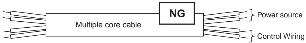
5) Control wiring and power source line should not be wired on the same multiple core cable.
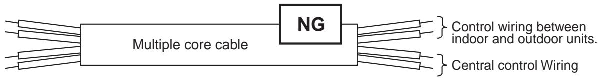
6) Don't wire two or more control wires on the same multiple core cable.
7) When the high harmonic devices exit near the air conditioner, place the air conditioner 3m or more far from these devices.
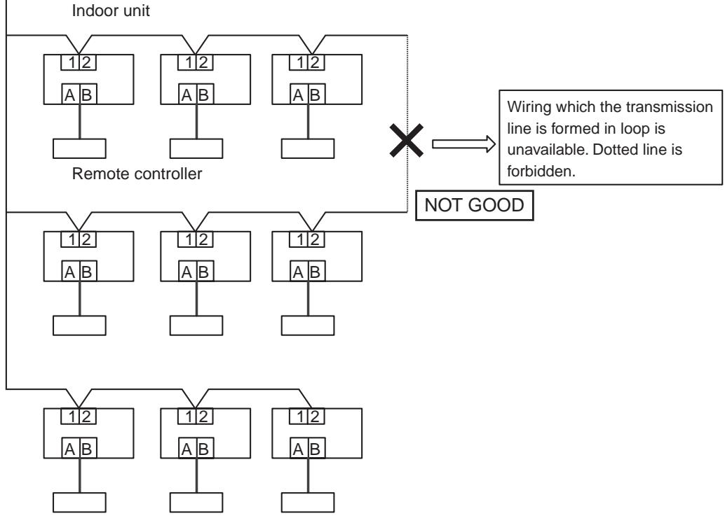
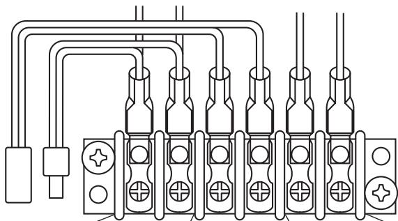
NOTE
4 or more control wires connected to one terminal is prohibited.
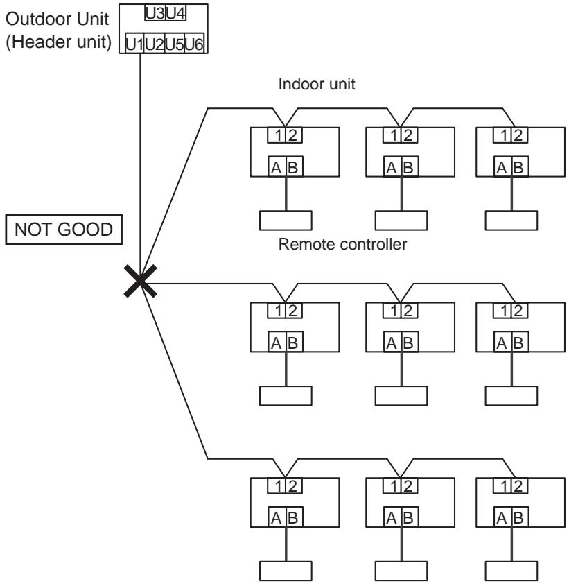
NOTE
Loop wiring of control wires is prohibited.
Outdoor Unit (Header unit)
ADDRESS SETUP
3-1 Definition of address
3-2 Address setup procedure
3-2-1 Check at main power-ON
3-2-2 Automatic address setup
3-2-3 Manual address setup from remote controller
3-2-4 Confirmation of indoor unit address and position by using the remote controller
3-2-5 Change of indoor address from remote controller
3-2-6 Address setup example (VRF system)
3-2-7 Clearance of address (Return to status (Address undecided) at shipment from factory)
3-2-8 In case of increase the address-undefined indoor units (Extension, etc.)
3-2-9 How to set central control address
3-2-10 Address re-setup for central control of the super-digital inverter and the digital inverter
3-2-11 Indoor address change example (Super-digital inverter and digital inverter)
3-1 Definition of address
Indoor unit address
- "Indoor unit address" is to make outdoor unit recognize an individual indoor unit.
This indoor unit address is allocated to every indoor unit one by one for every refrigerant system.
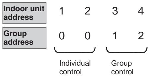
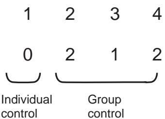
Group address
- "Group address" is the address to recognize group control and decide the header indoor unit and the follower indoor unit.
Group address and header indoor unit is decided automatically when automatic address setting is performed. (Which indoor unit becomes the header unit is indefinite when automatic address setting is performed.)
Indoor unit on individual control : Group address = 0 (at shipment)
Header indoor unit of group control : Group address = 1
Follower indoor unit of group control : Group address = 2
Line address (System address)
- "Line address" is the address with which line (refrigerant system) indoor units are connected.
This line address is set by switch setting on interface P.C. board of the header outdoor unit.
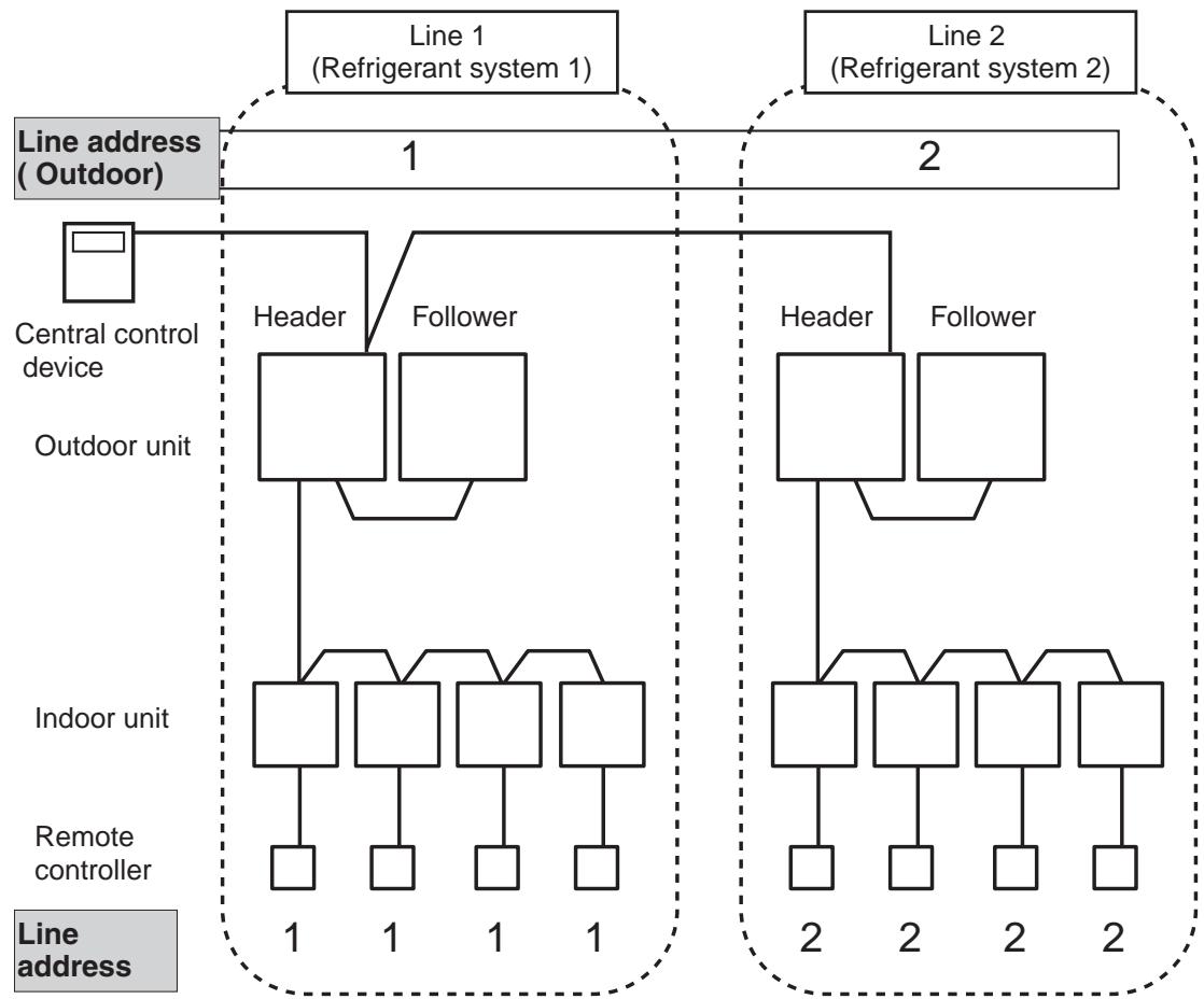
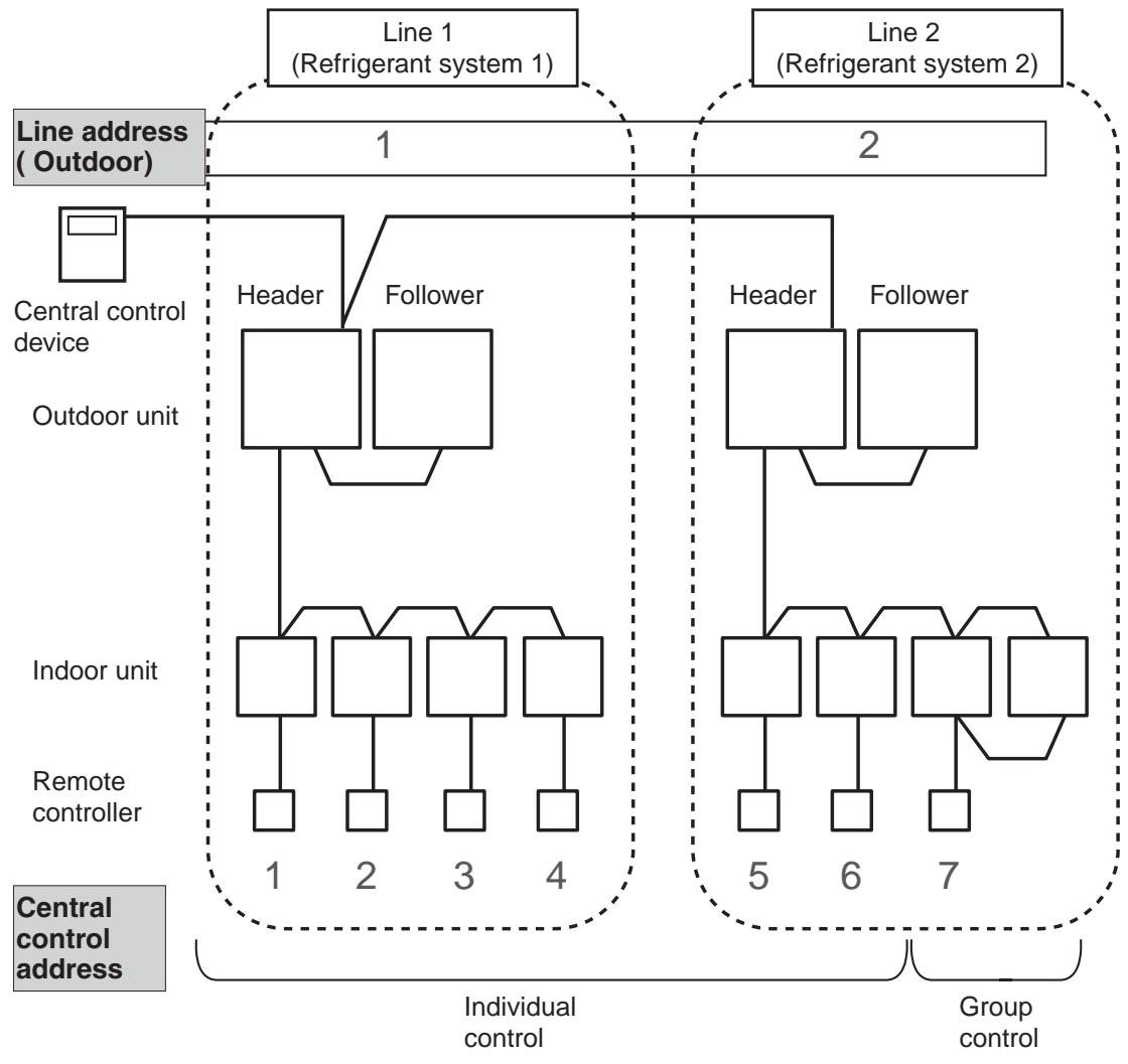
Central control address
- "Central control address" is to make central control devices recognize each indoor unit.
This address can be set from central control devices automatically or manually.
In case of group control on VRF system, one central control address is allocated to each indoor unit in a group control.
Zone address (Zone No.)
- "Zone address" is to be set when the central remote controller is used for each zone.
Zone address is set by switch setting on central remote controller.
Central remote controller can divide all indoor units into max. 4 zone.
The zone to which the indoor unit belongs is decided by its central control address.
| Central control address | Zone No. |
| 1 to 16 | Zone 1 |
| 17 to 32 | Zone 2 |
| 33 to 48 | Zone 3 |
| 49 to 64 | Zone 4 |
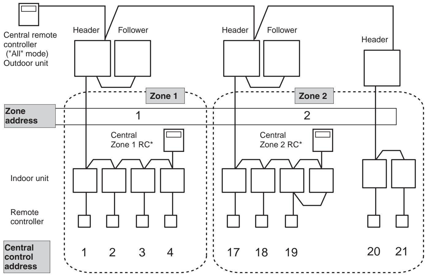
* RC: Remote controller
3-2 Address setup procedure
In this air conditioner, it is required to set up address to the indoor unit before starting operation. Set up the address according to the following setup procedure.
CAUTIONS
- Set up address after wiring work.
- Be sure to turn on the power in order of indoor unit outdoor unit. If turning on the power in the reverse order, a check code [E19] (Error of No. of header units) is output. When a check code is output, turn on the power again.
- It requires maximum 10 minutes (Usually, approx. 5 minutes) to set up automatically an address to 1 line.
- To set up an address automatically, the setup at outdoor side is necessary. (Address setup cannot be performed by power-ON only.)
- To set up an address, it is unnecessary to operate the air conditioner.
- Manual address setup is also available besides automatic setup.
Automatic address : Setup from SW15 on the interface P.C. board of the header unit
Manual address : Setup from the wired remote controller
- It is temporarily necessary to set the indoor unit and wired to 1 by 1.
(In group operation and in time without remote controller)
Address setting flow
Line address setting (Dip switch)
On the interface
P.C. board of outdoor unit
Power - ON
Automatic address setting
Manual address setting
Indoor / Group / Line address setting
For each refrigerant system
Trial operation
Setup of relay connector and SW30-2
On the interface P.C. board of outdoor unit
Central control address setting
3-2-1 Check at main power-ON
After turning on the main power of the indoor units and outdoor unit in the refrigerant system to be executed with a test operation, check the following items in each outdoor and indoor unit.
(After turning on the main power, be sure to check in order of indoor unit outdoor unit.)
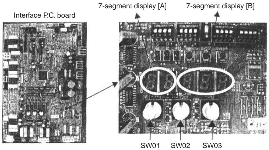
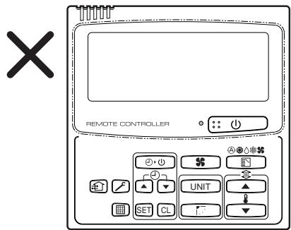
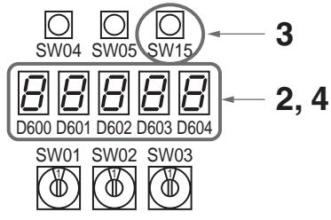
- Check that all the rotary switches, SW01, SW02, and SW03 on the interface P.C. board of the header outdoor unit are set up to "1".
- If other error code is displayed on 7-segment [B], remove the cause of trouble.
- Check that [L08] is displayed on 7-segment display [B] on the interface P.C. board of the header outdoor unit. (L08: Indoor address unset up)
(If the address setup operation has already finished in service time, etc, the above check code is not displayed, and only [U1] is displayed on 7-segment display [A].)
- Display check on remote controller (In case of wired remote controller)
Check that a frame as shown in the following left figure is displayed on LC display section of the remote controller.
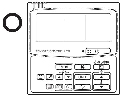
Normal status (Power and operation stop)
Abnormal status (Power is not normally turned on.)
If a frame is not displayed as shown in the above right figure, the power of the remote controller is not normally turned on. Therefore check the following items.
- Check power supply of indoor unit.
- Check wiring between indoor unit and remote controller.
- Check whether there is cutoff of cable around the indoor control P.C. board or not, and check connection failure of connectors.
- Check failure of transformer for the indoor microcomputer.
- Check indoor control P.C. board failure.
3-2-2 Automatic address setup
Without central control : To the address setup procedure 1
With central control : To the address setup procedure 2
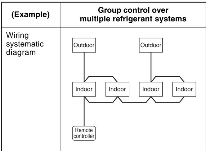
(However, go to the procedure 1 when the central control is performed in a single refrigerant system.)
| (Example) | In case of central control in a single refrigerant system | In case of central control over refrigerant systems | ||||||
| Address setup procedure | To procedure 1 | To procedure 2 | ||||||
| Cable systematic diagram | Outdoor | Central control remote controller | Outdoor | Central control remote controller | Outdoor | Outdoor | Central control remote controller | |
| Indoor | Indoor | Indoor | Indoor | Indoor | Indoor | Indoor | Indoor | |
| Remote controller | Remote controller | Remote controller | Remote controller | Remote controller | Remote controller | |||
Address setup procedure 1
- Turn on power of indoor/outdoor units. (In order of indoor Outdoor)
- After approx. 1 minute, check that U.1.L08 (U.1-flash) is displayed in 7-segment display section on the interface P.C. board of the header outdoor unit.
- Push SW15 and start setup the automatic address. (Max. 10 minutes for 1 refrigerant system (Usually, approx. 5 minutes))
- When the count Auto 1 Auto 2 Auto 3 is displayed in 7-segment display section, and it changes from U.1.--(U.1.flash) to U.1.--(U.1.light), the setup finished.
- When perform a central control, connect a relay connector between [U1, U2] and [U3, U4] terminals in the header unit.
Header unit interface P.C. board
REQUIREMENT
- When a group control is performed over the multiple refrigerant systems, be sure to turn on the power supplies of all the indoor units connected in a group in the time of address setup.
- If turning on the power for each refrigerant system to set up address, a header indoor unit is set for each line. Therefore, an alarm code "L03" (Duplicated indoor header units) is output in operation after address setup. In this case, change the group address from the wired remote controller so that only one header indoor unit is set up.
Address setup procedure 2
- Using SW13 and 14 on the interface P.C. board of the header outdoor unit in each system, set up the line (system) address for each system. (At shipment from factory: Set to Address 1)
Note) Be careful not to duplicate with other refrigerant system.
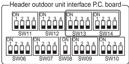
Line (system) address switch on outdoor interface P.C. board
(O: Switch ON, x : Switch OFF)
: Is not used for setup of line address. (Do not change setup.)
- Check that the relay connectors between [U1U2] and [U3U4] terminals are disconnected in all the header outdoor units to which the central control is connected. (At shipment from factory: No connection of connector)
- Turn on power of indoor/outdoor. (In order of indoor outdoor)
- After approx. 1 minute, check that 7-segment display is U.1.L08 (U.1 flash) on the interface P.C. board of the header outdoor unit.
- Push SW15 and start setup the automatic address. (Max. 10 minutes for 1 refrigerant system (Usually, approx. 5 minutes))
- When the count Auto 1 Auto 2 Auto 3 is displayed in 7-segment display section, and it changes from U.1.--(U.1.flash) to U.1.--(U.1.light), the setup finished.
- Procedure 4. to 6. are repeated in other refrigerant systems.
-
How to set up terminator resistor (SW30) When all the address setups have finished in the same refrigerant system, put the terminator resistor (SW30) in the same central control line into one.
-
Remain only SW30-2 of the header outdoor unit with the least line address number as it is ON. (With terminator resistor)
-
Set up SW30-2 of the other header outdoor units to OFF. (Without terminator resistor)
-
Connect the relay connector between [U1U2] and [U3U4] of the header outdoor unit for each refrigerant system.
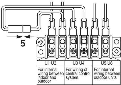
2
| U1 U2 | U3 U4 | U5 U6 |
| For internal wiring between indoor and outdoor | For wiring of central control system | For internal wiring between outdoor units |

- Then set up the central control address.
(For the central control address setup, refer to the installation manual of the central control devices.)
| 1 | 2 | 3 | ||||||
| Before address setup during setup of address | Header unit U3U4 U1U2 U5U6 Relay connector U1U2 A B Remote controller Individual | Header unit U3U4 U1U2 U5U6 Relay connector U1U2 A B Remote controller Group | Header unit U3U4 U1U2 U5U6 Relay connector U1U2 A B Remote controller Group | |||||
| After address setup | Header unit U3U4 U1U2 SW30 OFF U1U2 U5U6 Relay connector U1U2 A B Remote controller Individual | Header unit U3U4 U1U2 SW30 OFF U1U2 U5U6 Relay connector U1U2 A B Remote controller Group | Header unit U3U4 U1U2 SW30 OFF U1U2 A B Remote controller Group | |||||
| Outdoor interface P.C. board | Header unit | Follower unit | Header unit | Follower unit | Header unit | |||
| SW13, 14 (Line address) | 1 | (Setup is unnecessary.) | 2 | (Setup is unnecessary.) | 3 | |||
| SW30-2 Terminator resistor of indoor/outdoor communication line/central control communication line | ON | (Setup is unnecessary.) | OFF after address setup | (Setup is unnecessary.) | OFF after address setup | |||
| Relay connector | Connect short after address setup | Open | Connect short after address setup | Open | Connect short after address setup | |||
Indoor side (Automatic setup)
| Line address | 1 | 1 | 2 | 2 | 3 |
| Indoor unit address | 1 | 2 | 1 | 2 | 1 |
| Group address | 0 | 0 | 1 | 2 | 0 |
Relay connector -NOTE -
Never connect a relay connector until address setup for all the refrigerant systems finishes; otherwise address cannot be correctly set up.
3-2-3 Manual address setup from remote controller
In case to decide an address of the indoor unit prior to finish of indoor cabling work and unpracticed outdoor cabling work (Manual setup from remote controller)
Arrange one indoor unit and one remote controller set to 1 by 1.
Turn on the power.
(Wiring example in 2 systems)
In the above example, under condition of no inter-unit wire of the remote controller, set the address after individual connecting of the wired remote controller.
Group address
Individual : 0000
Header unit :0001 Follower unit:0002 In case of group control
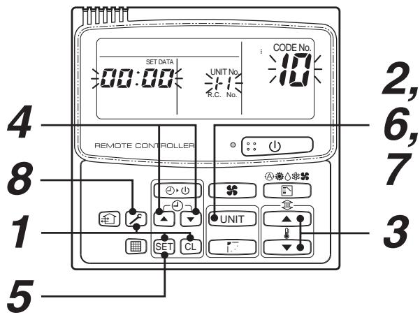
Operation procedure
$$ \begin{array}{l} 1 \rightarrow 2 \rightarrow 3 \rightarrow 4 \rightarrow 5 \rightarrow 6 \rightarrow \ 7 \rightarrow 8 \rightarrow 9 \rightarrow 1 0 \rightarrow 1 1 \text {E n d} \ \end{array} $$
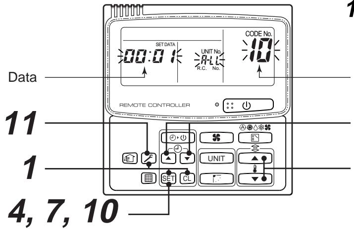
1 Push simultaneously SET + CL + f buttons for 4 seconds or more. LCD changes to flashing.
(Line address)
2 Using the setup temp. / buttons, set to the item code.
3 Using the timer time / buttons, set up the line address. (Match it with the line address on the interface P.C. board of the header unit in the identical refrigerant system.)
4 Push SET button. (OK when display goes on.)
(Indoor address)
5 Using the setup temp. / buttons, set to the item code.
6 Using the timer time / buttons, set up the indoor address.
7 Push SET button. (OK when display goes on.)
(Group address)
8 Using the setup temp. / buttons, set 14 to the item code.
9 Using the timer time / buttons, set Individual = 0000 , Header unit = 0001 , Follower unit = 0002 .
10 Push SET button.
(OK when display goes on.)
11 Push button.
Setup operation finished.
(Status returns to normal stop status.)
Item code
$$ 3, 6, 9 $$
$$ 2, 5, 8 $$
Note 1)
When setting the line address from the remote controller, do not use address 29 and 30.
The address 29 and 30 cannot be set up in the outdoor unit. Therefore if they are incorrectly set up, a check code [E04] (Indoor/outdoor communication circuit error) is output.
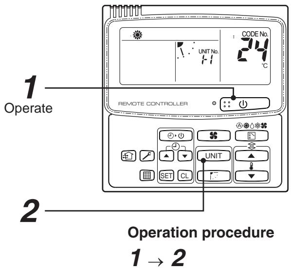
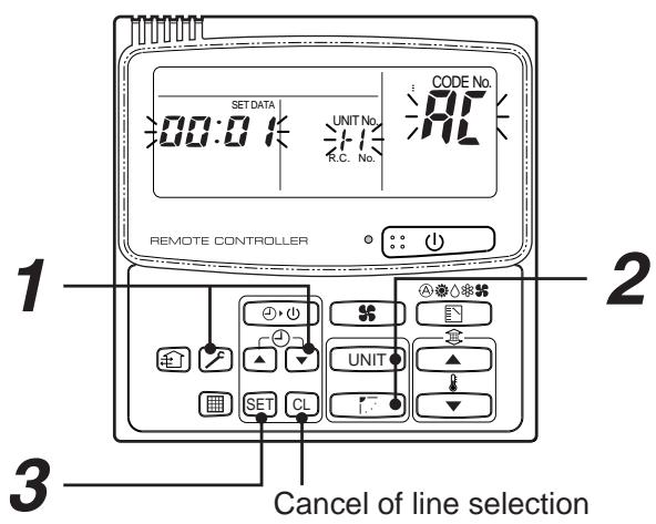
3-2-4 Confirmation of indoor unit address and position by using the remote controller
[Confirmation of indoor unit address and the position]
1. When you want to know the indoor address though position of the indoor unit itself can be recognized;
1 If it stops, push button.
2 Push UNIT button.
The unit NO f - f is displayed on the LCD. (Disappears after several seconds) The displayed unit No indicates the line address and indoor address. (If there is other indoor unit connected to the same remote controller (Group control unit), other unit No is displayed every pushing UNIT button.)
2. When you want to know position of the indoor unit using the address
- To confirm the unit numbers in a group control;
The indoor unit numbers in a group control are successively displayed, and the corresponding indoor fan is turned on. (Operation while the air conditioner stops)
1 Push = + buttons simultaneously for 4 seconds or more.
- Unit No R L L is displayed.
- The fans of all the indoor units in a group control are turned on.
2 Every pushing UNIT button, the indoor unit numbers in the group control are successively displayed.
- The firstly displayed unit No indicates the address of the header unit.
- Only fan of the selected indoor unit is turned on.
3 Push button to finish the procedure.
All the indoor units in group control stop.
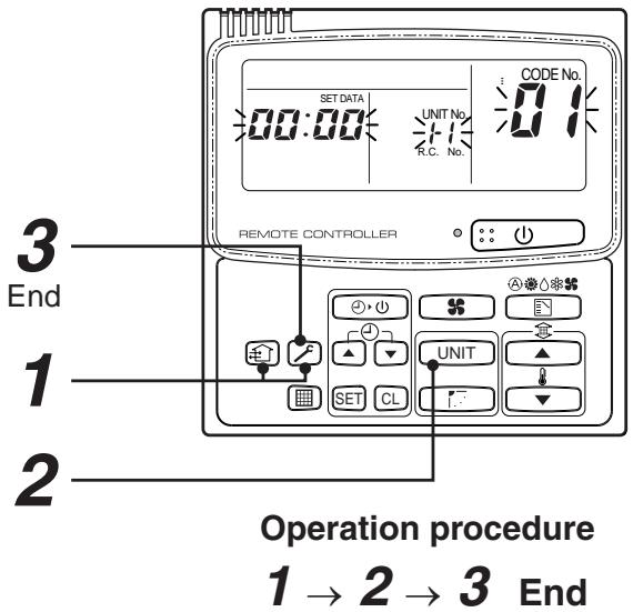
- To confirm all the unit numbers from an arbitrary wired remote controller;
The indoor unit No and position in the same refrigerant piping can be confirmed. An outdoor unit is selected, the indoor unit numbers in the same refrigerant piping are successively displayed, and then its indoor unit fan is turned on.
1 Push the timer time + buttons simultaneously for 4 seconds or more.
Firstly, the line 1, item code R (Address Change) is displayed. (Select outdoor unit.)
2 Using UNIT + buttons, select the line address.
3 Using SET button, determine the selected line address.
- The indoor unit address, which is connected to the refrigerant pipe of the selected outdoor unit is displayed and the fan is turned on.
4 Every pushing UNIT button, the indoor unit numbers in the identical pipe are successively displayed.
- Only fan of the selected indoor unit operates.
[To select another line address]
5 Push CL button to return to procedure 2.
- The indoor address of another line can be successively confirmed.
6 Push button to finish the procedure.
Operation procedure
$$ \begin{array}{l} 1 \rightarrow 2 \rightarrow 3 \rightarrow \ 4 \rightarrow 5 \rightarrow 6 E n d \ \end{array} $$
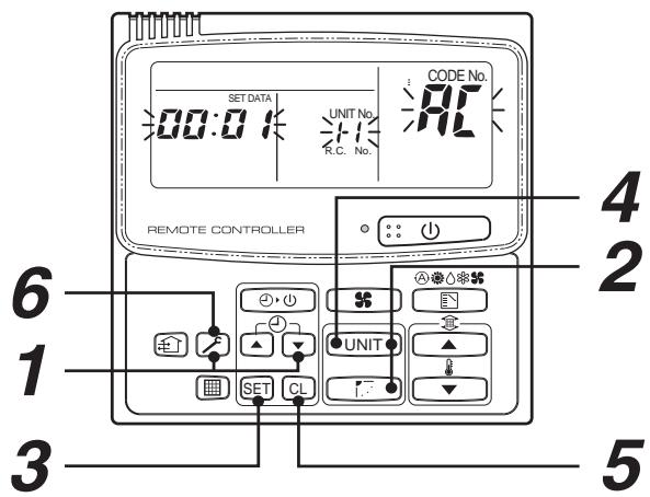
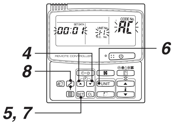
3-2-5 Change of indoor address from remote controller
Change of indoor address from wired remote controller
- To change the indoor address in individual operation (Wired remote controller : Indoor unit = 1 : 1) or group control (When the setup operation with automatic address has finished, this change is available.)
1 Push simultaneously SET + CL + buttons for 4 seconds or more.
(The firstly displayed unit No indicates the header unit in group control.)
2 In group control, select an indoor unit No to be changed by UNIT button.
(The fan of the selected indoor unit is turned on.)
3 Using the setup temp. / buttons, set 13 to the item code.
4 Using the timer time / buttons, change the displayed setup data to a data which you want to change.
5 Push SET button.
6 Using the UNIT button, select the unit No. to be changed at the next time. Repeat the procedure 4 to 6 and change the indoor address so that it is not duplicated.
7 After the above change, push UNIT button to confirm the changed contents.
8 If it is acceptable, push button to finish confirmation.
Operation procedure
$$ \begin{array}{l} 1 \rightarrow 2 \rightarrow 3 \rightarrow 4 \rightarrow \ \mathbf {5} \rightarrow \mathbf {6} \rightarrow \mathbf {7} \rightarrow \mathbf {8} E n d \ \end{array} $$
- To change all the indoor addresses from an arbitrary wired remote controller;
(When the setup operation with automatic address has finished, this change is available.)
Contents : Using an arbitrary wired remote controller, the indoor unit address can be changed for each same refrigerant system
* Change the address in the address check/change mode.
1 Push the timer time + buttons simultaneously for 4 seconds or more.
Firstly, the line 1, item code R (Address Change) is displayed.
2 Using UNIT + buttons, select the line address.
3 Push SET button.
- The indoor unit address, which is connected to the refrigerant system of the selected outdoor unit is displayed and the fan is turned on.
First the current indoor address is displayed on the setup data. (Line address is not displayed.)
4 The indoor address of the setup data moves up/down by the timer time / buttons.
Change the setup data to a new address.
5 Push SET button to determine the setup data.
6 Every pushing UNIT button, the indoor unit numbers in the identical pipe are successively displayed. Only fan of the selected indoor unit operates.
Repeat the procedure 4 to 6 and change all the indoor addresses so that they are not duplicated.
7 Push SET button.
(All the displays on LCD go on.)
8 Push button to finish the procedure.
To finish the setup
Here, if the unit No is not called up, the outdoor unit in this line does not exist.
Push CL button, and then select a line according to procedure 2.
Operation procedure
1 2 3 4
±b5 ±b6 ±b7 ±b8 End
3-2-6 Address setup example (VRF system)
[Automatic address / Manual address setup example]
Individual control
| Automatic address setting | Available | Available | ||||
| Outdoor | Line address | 1 | 1 | |||
| Configuration | Outdoor Indoor RC Master | Indoor RC Master | Outdoor Indoor RC 1 Master | Indoor RC 2 Side Master | RC 3 Side Master | |
| Indoor | Line address | 1 | 1 | 1 | 1 | |
| Indoor unit address | 1 | 2 | 1 | 2 | ||
| Group address | 0 | 0 | 0 | 0 | ||
- RC: Remote controller
| Automatic address setting | Available | Available | Available | ||||
| Outdoor | Line address | 1 | 1 | 1 | |||
| Configuration | Receiver unit Wireless RC. | Master | Receiver unit Wireless RC. | Master | Receiver unit Wireless RC. | Master | |
| Indoor | Line address | 1 | 1 | 1 | 1 | 1 | 1 |
| Indoor unit address | 1 | 2 | 1 | 2 | 1 | 2 | |
| Group address | 0 | 0 | 0 | 0 | 0 | 0 | |
Group control
| Automatic address setting | Available | Available | Available | ||||
| Outdoor | Line address | 1 | 1 | 1 | |||
| Configuration | Outdoor Indoor RC Master | Outdoor Indoor Receiver unit Wireless RC. | Outdoor Indoor RC Master | Receiver unit Side Wireless RC. | |||
| Indoor | Line address | 1 | 1 | 1 | 1 | 1 | 1 |
| Indoor unit address | 1 | 2 | 1 | 2 | 1 | 2 | |
| Group address | 1 | 2 | 1 | 2 | 1 | 2 | |
Central control (Multiple refrigerant systems)
| Automatic address setting | Available | Available | |||||||
| Outdoor | Line address | 1 | 2 | 1 | 2 | ||||
| Configuration | Central remote controller | Central remote controller | |||||||
| Outdoor | Outdoor | Outdoor | Outdoor | ||||||
| Individual control | Individual control | Group control | Group control | ||||||
| Indoor | Indoor | Indoor | Indoor | ||||||
| RC Master | RC Master | RC Master | RC Master | ||||||
| Indoor | Line address | 1 | 1 | 2 | 2 | 1 | 1 | 2 | 2 |
| Indoor unit address | 1 | 2 | 1 | 2 | 1 | 2 | 1 | 2 | |
| Group address | 0 | 0 | 0 | 0 | 1 | 2 | 1 | 2 | |
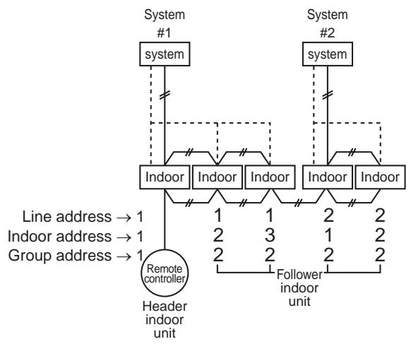
Group control over other refrigerant systems
| Automatic address setting | Available (*1) | |||||||
| Outdoor | Line address | 1 | 2 | 1 | ||||
| Configuration | Outdoor Indoor RC Master | |||||||
| Indoor | Line address | 1 | 1 | 2 | 2 | 2 | 3 | 3 |
| Indoor unit address | 1 | 2 | 1 | 2 | 3 | 1 | 2 | |
| Group address | 1 | 2 | 2 | 2 | 2 | 2 | 2 | |
| Group address | 1 | 2 | 1 → 2* | 2 | 2 | 1 → 2* | 2 |
^*1 In case of group control over refrigerant systems, automatic address setting is available only when all indoor units connected to a group control are turned on during address setting.
If an automatic address setting is conducted under condition of power-ON only in the refrigerant system in which address set up, it will cause the error code "L03" (Duplicated indoor header units) because indoor header units exit for each refrigerant system. In this case, change the group address by the wired remote controller so that only one indoor unit becomes the header unit in one group control.
It is necessary to change the group address as marked with * when an automatic address setting is conducted under condition of power-ON only in the refrigerant system in which address set up.
| Automatic address setting | Available (*1) | |||||||
| Outdoor | Line address | 1 | 2 | 1 | ||||
| Configuration | Outdoor Indoor RC Master Wireless RC. | |||||||
| Indoor | Line address | 1 | 1 | 2 | 2 | 2 | 3 | 3 |
| Indoor unit address | 1 | 2 | 1 | 2 | 3 | 1 | 2 | |
| Group address | 1 | 2 | 2 | 2 | 2 | 2 | 2 | |
| Group address | 1 | 2 | 1 → 2* | 2 | 2 | 1 → 2* | 2 |
^*1 In case of group control over refrigerant systems, automatic address setting is available only when all indoor units connected to a group control are turned on during address setting.
If an automatic address setting is conducted under condition of power-ON only in the refrigerant system in which address set up, it will cause the error code "L03" (Duplicated indoor header units) because indoor header units exit for each refrigerant system. In this case, change the group address by the wired remote controller so that only one indoor unit becomes the header unit in one group control.
It is necessary to change the group address as marked with * when an automatic address setting is conducted under condition of power-ON only in the refrigerant system in which address set up.
3-2-7 Clearance of address (Return to status (Address undecided) at shipment from factory)
Method 1
An address is individually cleared from a wired remote controller.
"0099" is set up to line address, indoor address, and group address data from the remote controller.
(For the setup procedure, refer to the abovementioned address setup from the remote controller.)
Method 2
Clear the indoor addresses in the same refrigerant line from the outdoor unit.
- Turn off the power of the refrigerant system to be returned to the status at shipment, and change the header outdoor unit to the following status.
1) Remove the relay connector between [U1U2] and [U3U4]. (If it has been already removed, leave it as it is.)
2) Turn on SW30-2 on the interface P.C. board of the header outdoor unit if it is ON. (If it has been already ON, leave it as it is.)
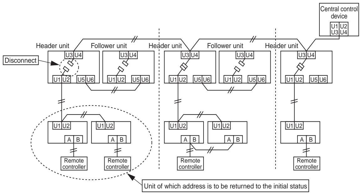
- Turn on the indoor/outdoor power of which address is to be cleared. After approx. 1 minute, check that "U.1. - - -" is displayed, and then execute the following operation on the interface P.C. board of the header outdoor unit of which address is to be cleared in the refrigerant system.
| SW01 | SW02 | SW03 | SW04 | Address which can be cleared |
| 2 | 1 | 2 | After checking that “A.d.buS” is displayed on 7-degment display, and then push SW04 for 5 seconds or more. | Line + Indoor + Group address |
| 2 | 2 | 2 | After checking that “A.d.nEt” is displayed on 7-degment display, and then push SW04 for 5 seconds or more. | Central control address |
- After "A.d. c.L." has been displayed on 7-degment display, return SW01/SW02/SW03 to 1/1/1.
- When the address clearing has correctly finished, "U.1.L08" is displayed on 7-degment display after a while. If "A.d. n.G." is displayed on 7-degment display, there is a possibility which is connected with the other refrigerant system. Check again the relay connector between [U1U2] and [U3U4] terminals.
NOTE) Be careful that the other line address may be also cleared if clearing operation is not correctly executed.
- After clearing of the address, set up an address again.
3-2-8 In case of increase the address-undefined indoor units (Extension, etc.)
If set up the indoor address of which address is undefined accompanied with extension of indoor units, replacement of P.C. board, etc, follow to the methods below.
Method 1
Set up an address individually from a wired remote controller.
(Line address, Indoor address, Group address, Central control address)
For the setup method, refer to the above "Manual address setup from remote controller".
Method 2
Set up an address from the outdoor unit.
- Leave the address of the unit of which address has been already set up as it is.
Set up an address only to the unit of which address is undefined.
The addresses are allocated from the low number.
Setup procedure
Arrange the outdoor header units in the refrigerant line to which indoor units are added. (Figure below)
- Remove the relay connector between [U1U2] and [U3U4].
-
Turn on SW30-2 on the interface P.C. board at outdoor header unit side if it is ON.
-
Turn off the power, and then execute the operation.

- Turn on the indoor/outdoor power of which address is to be set up. After approx. 1 minute, check that "U.1----" is displayed on 7-segment display.
- Execute the following operation on the interface P.C. board of the header outdoor unit.
| SW01 | SW02 | SW03 | SW04 |
| 2 | 14 | 2 | After checking that “In.At” is displayed on 7-segment display, and then push SW04 for 5 seconds or more. |
"AUTO1" "AUTO2" "AUTO3" ... is counted and displayed on 7-degment display.
- When "U.1.---" is displayed on 7-segment display, the setup operation finished.
Turn off the indoor/outdoor power.
- Return the following setup as before.
Relay connector
SW30-2
- SW01, 02, 03
3-2-9 How to set central control address
(Note)
1) Perform after the setting of indoor and outdoor unit address (Indoor/group/line address).
2) Three setting address method can be selected.
① Manual setting from wired main remote controller (RBC-AMT21E)
② Manual setting from central control remote controller (TCB-SC642TLE)
③ Automatic setting from central remote controller (TCB-SC642TLE)
REQUIREMENT
- Be sure to reconfirm the following status for all header outdoor units before the central control address setting.
[1] Check that the relay connectors between [U1,U2] and [U3,U4] terminals are disconnected in all header outdoor units to which the central control is connected.
(At the shipment from factory: No connection of connector)
[2] SW30-2 should be OFF in all header unit except the header unit with the least line address number. (At the shipment from factory : Set to ON) - Correct address setting can't be conducted without the setting status above mentioned.
- The procedure above mentioned should be conducted after address setting of all indoor and outdoor units.
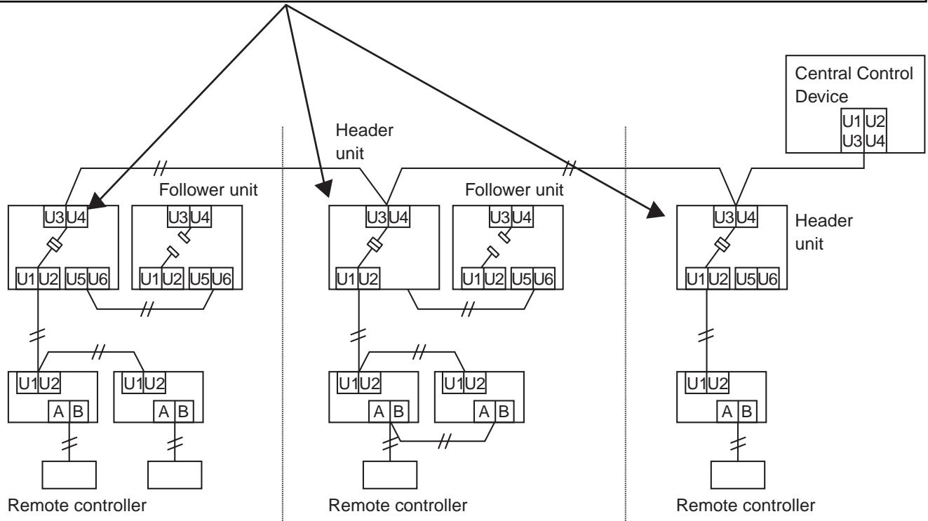
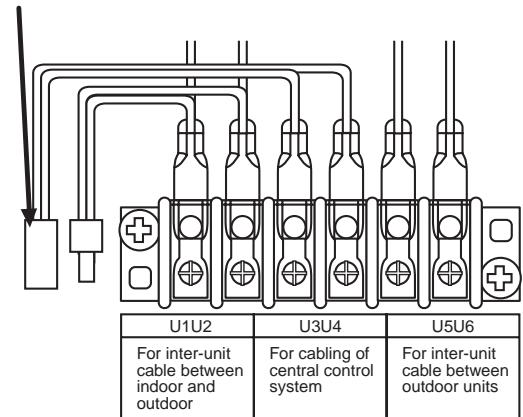
Relay connector
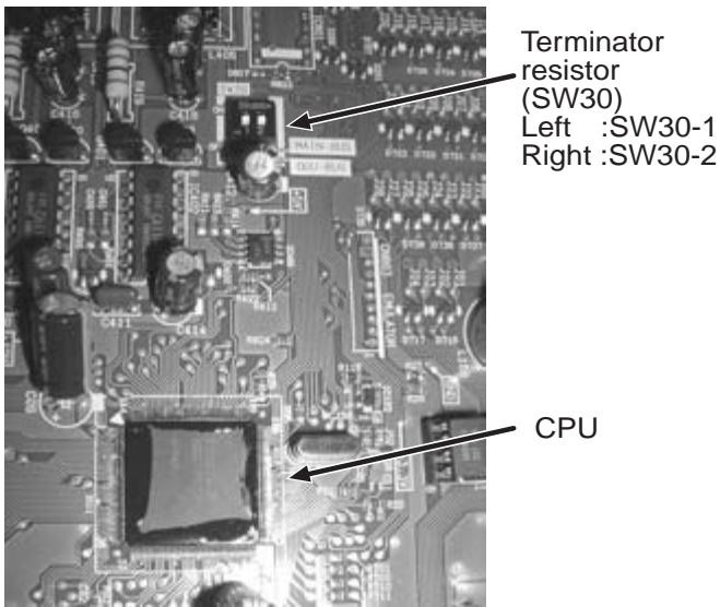
Interface P.C. board on the outdoor unit.
Flow chart of setting central control address
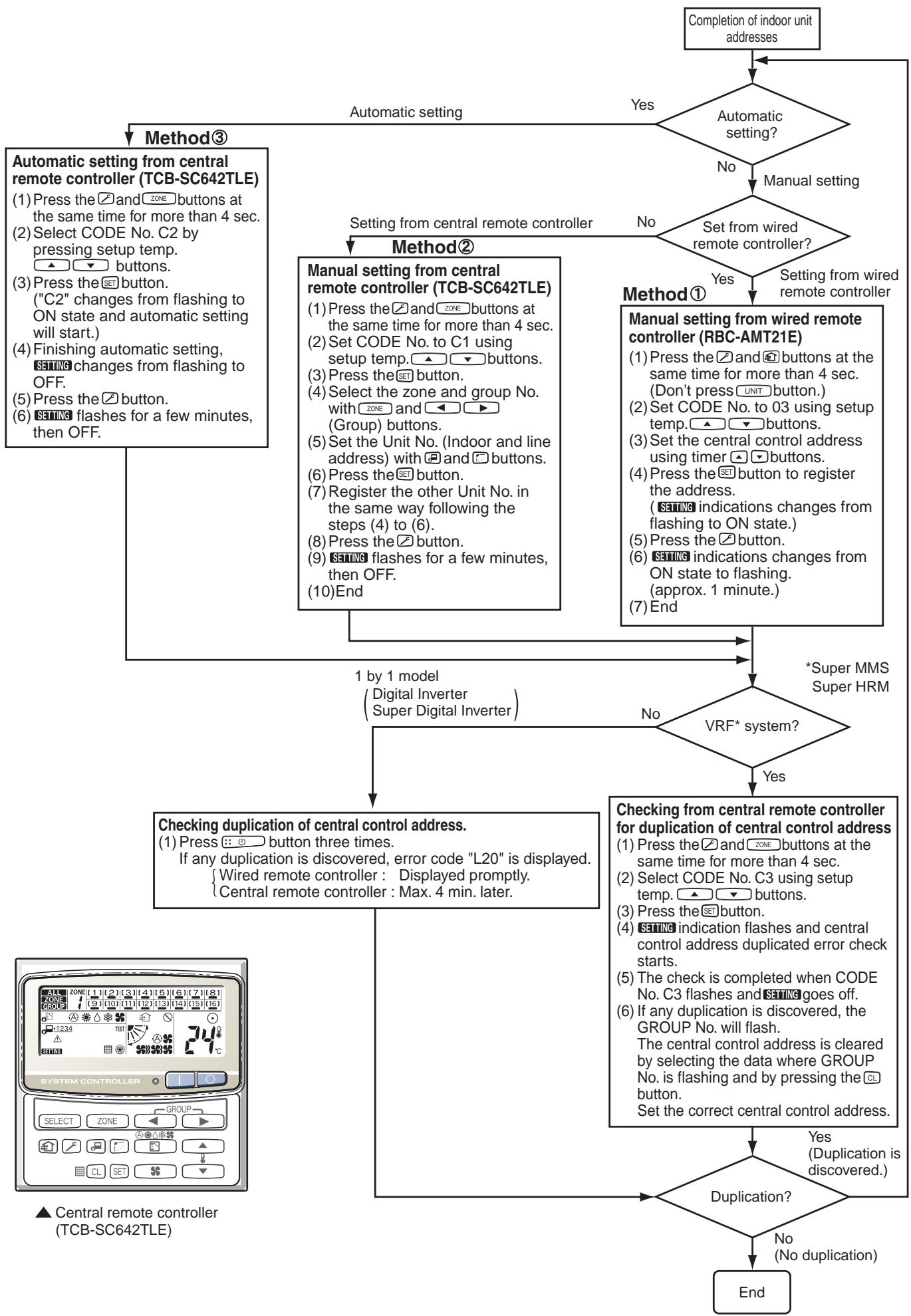
3-2-10 Address re-setup for central control of the super-digital inverter and the digital inverter
POINT1
When controlling the super-digital inverter and the digital inverter, the adaptor named "1:1 model" connection interface (TCB-PCNT30TLE) is necessary.
1. Cabling connection of control wiring
Attach an adaptor per 1 group in group control operation (including individual control).
Connect the adaptor to the header indoor unit in the group control. (For details, see POINT 3.)

2. Cabling connection diagram with indoor control P.C. board
- For details, refer to Installation Manual.

- Parts included in the single-point chain line are optional accessories.
- There is non-polarity on the cables connected to U3 and U4 terminals.
POINT 2
After automatic address setup, it is necessary to change the line address from the wired remote controller for each system. (Manual re-setup)
Reason :After automatic address setup, all the line addresses become “1” except a group control and then a duplicated address error “E08” is output.
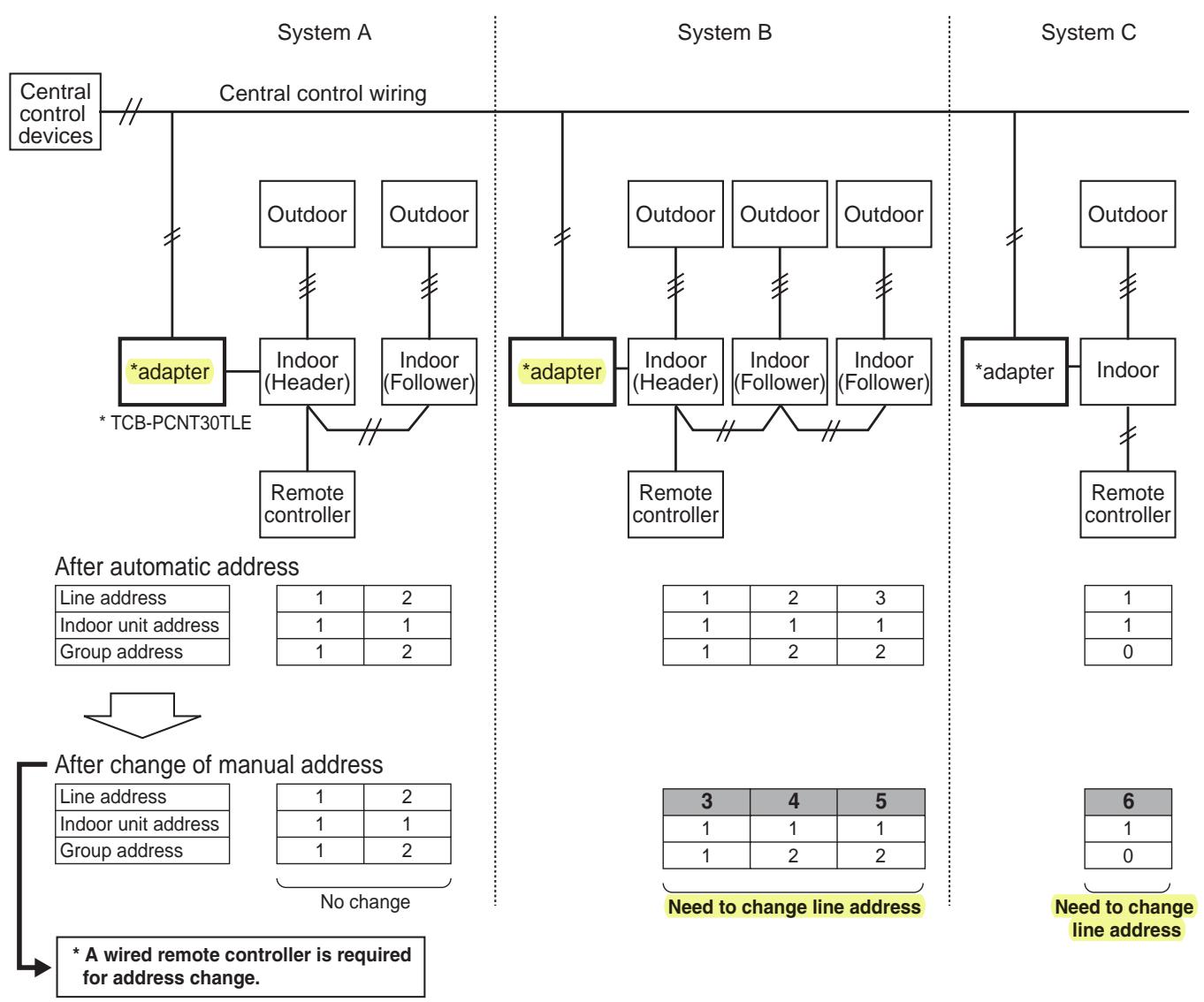
- Set up a line address for each refrigerant system.
- Set up a line address so that it is not duplicated with other systems.
(If the central control is conducted with VRF systems, set up a line address so that it is not also duplicated with line address of VRF systems.)
- When performing a central control over 30 systems, the address setup method is necessary to be changed. (including VRF system)
POINT 3
When the central control is performed for indoor units of twin control in a group control, it may be required to change the group address. (Adapter is attached to the header indoor unit.)
Reason : The central control device communicates with individual indoor unit, header indoor unit of the group control, and header indoor unit of twin control. However, as the address is automatically set up, which unit will become the header unit is indefinite. Therefore if the unit attached with adapter would not become the header indoor unit, a central control is unavailable.

How to check group address (Header/Follower indoor unit setup)
- Check the group address after confirming which unit is attached with the adapter.
1 Push SET + CL + f buttons simultaneously for 4 seconds or more.
2 The indoor unit in which the fan is turned on is the header indoor unit.

Indoor unit in which the fan is turned on = Indoor unit with the adapter : To Case 1
Indoor unit in which the fan is turned on Indoor unit with the adapter : To Case 2
Case 1
(In case that the indoor unit in which the fan is turned on and the unit with the adapter are same)
3 As the central control is available, push button. (Setup is determined.)
When pushing the button, the display disappears and the status returns to the normal stop status.
(The operation on the remote controller is not accepted for approx. 1 minute after the button has been pushed.)
If the operation on the remote controller is not accepted for 1 minute or more after button has been pushed, an incorrect address setup is considered.
In this case, automatic address is performed again. After approx. 5 minutes or more, and set up again the group address from
Case 2
(In case that the indoor unit in which the fan is turned on and the unit from
As the central control is unavailable, change the address in the following procedure.
3 Using the setup temp + buttons, select Item code 14.
4 Check the setup data is 0001 and change the setup data from 0001 to 0002 using the timer + buttons.
5 Push the SET button. In this time, the setup has finished if the display changes from flashing to lighting.
6 Push the UNIT button to turn on the fan of the indoor unit attached with the adaptor.
7 Using the setup temp + buttons, select Item code 14.
8 Check the setup data is 0002 and change the setup data from 0002 to 0001 using the timer + buttons.
9 Push the SET button.
In this time, the setup has finished if the display changes from flashing to lighting.
10 When the above setup operation has finished, push the UNIT button to select the indoor unit of which setup has been changed. Using the setup temp + buttons, specify the Item code 14 and check the changed contents.
Pushing the CL button enables to clear the setup contents until now.
(In this case, repeat the procedure from 1.)
11 Push button. (Setup is determined.)
When pushing the button, the display disappears and the status returns to the normal stop status.
(The operation on the remote controller is not accepted for approx. 1 minute after the button has been pushed.)
If the operation on the remote controller is not accepted for 1 minute or more after button has been pushed, an incorrect address setup is considered.
In this case, automatic address is performed again. After approx. 5 minutes or more set up again the group address from
3-2-11 Indoor address change example (Super-digital inverter and digital inverter)
1 In case of central control up to 29 refrigerant systems (including No. of VRF systems)
| ■: adapter ("1:1 model" connection interface TCB-PCNT30TLE) | POINT 1) Change the line address for each refrigerant system. | ||||||||||
| Central control device | |||||||||||
| 1 | 2 | 3 | 4 | 5 | 6 | 7 | 8 | ||||
| Outdoor | Outdoor | Outdoor | Outdoor | Outdoor | Outdoor | Outdoor | Outdoor | ||||
| Indoor | Indoor | Indoor | Indoor | Indoor | Indoor | Indoor | Indoor | ||||
| RC | RC | RC | RC | RC | RC | *RC: Remote controller | |||||
| Line address | 1 | ① 1→2 | ① 1→3 | ① 1→3 | ① 1→4 | ① 2→5 | ① 1→6 | ① 2→6 | ① 2→7 | ① 2→7 | ① 3→8 |
| Indoor unit address | 1 | 1 | 1 | 2 | 1 | 1 | 1 | 3→2 | 1 | 2 | 1→2 |
| Group address | 0 | 0 | 1 | 2 | 1 | 2 | 1 | 2 | 2 | 2 | 2 |
Change the line address on wired remote controller after automatic address setting.
Automatic address is impossible. Set up again an address manually on wired remote controller.
2 In case of central control over 30 refrigerant systems (including No. of VRF systems if any) * Change operation is same to the above 1 up to 29th refrigerant system.
| □: adapter ("1:1 model" connection interface TCB-PCNT30TLE) | POINT 1) Set all the line addresses to 30 for all indoor units attached with the adapter. POINT 2) Change the indoor address so that the indoor unit address numbers are not duplicated. POINT 3) When the indoor unit with adaptor is in twin or triple control, change also the line address of the follower indoor unit to 30. | ||||||||||
| Central control device | |||||||||||
| 1 | 2 | 3 | 4 | 5 | 6 | 7 | 8 | ||||
| Outdoor | Outdoor | Outdoor | Outdoor | Outdoor | Outdoor | Outdoor | Outdoor | ||||
| Indoor | Indoor | Indoor | Indoor | Indoor | Indoor | Indoor | Indoor | ||||
| RC | RC | RC | RC | RC | RC | *RC: Remote controller | |||||
| Line address | 1 1→30 | 1 1→30 | 1 1→30 | 3 1→30 | 1 1→30 | 2 | 1 1→30 | 1 2→30 | 2 | 2 | 3 |
| Indoor unit address | 1 | 2 1→2 | 2 1→3 | 2 1→4 | 2 1→5 | 1 | 2 1→6 | 2 3→7 | 1 | 2 | 1→2 |
| Group address | 0 | 0 | 1 | 2 | 1 | 2 | 1 | 2 | 2 | 2 | 2 |
Change the line address on wired remote controller after automatic address setting.
Automatic address is impossible. Set up again an address manually on wired remote controller.
DETAILS OF
APPLICATION CONTROL
AND DEVICES
4-1 Remote controller
4-1-1 Wired remote controller (RBC-AMT21E)
4-1-2 Simple remote controller (RBC-AS21E)
4-1-3 Wireless remote controller kit
4-1-4 Weekly timer (RBC-EXW21E)
4-2 Central remote controller (TCB-SC642TLE)
4-2-1 Outline
4-2-2 Installation procedure
4-2-3 Operation procedure
4-3 Application controls of indoor unit
4-3-1 Setup of selecting function in indoor unit
4-3-2 Ventilation fan control from remote controller
4-3-3 Leaving-ON prevention control
4-3-4 Power peak-cut from indoor unit
4-3-5 Remote sensor (TCB-TC21LE)
4-4 Application controls of outdoor unit
4-4-1 Outdoor fan high static pressure shift
4-4-2 Cooling priority, heating priority control
4-4-3 Indoor unit setup in “Specific indoor unit priority control” mode
4-5 Application controls by optional P.C. board of outdoor unit
4-5-1 Power peak-cut control
4-5-2 Snowfall fan control
4-5-3 External master ON/OFF control
4-5-4 Night operation control
4-5-5 Operation mode selection control
4-6 Application controls by optional devices connected to indoor unit
4-6-1 Remote control by "remote location ON/OFF control box"
4-6-2 Central control by AI-NETWORK (Network adapter)
4-6-3 Central control with "1:1 model" ("1:1 model" connection interface)
4-1 Remote controller
4-1-1 Wired remote controller (RBC-AMT21E)
Accessory parts
| Part Name | Q'ty | Part Name | Q'ty |
| Remote controller (200mm-cable attached) | 1 | Spacer | 2 |
| Screw M4 x 25 | 2 | Wire joint | 2 |
| Wood screw | 2 | Installation Manual | 1 |
Requirement to install the remote controller
Installation place
Install the remote controller at a position with height 1 to 1.5m from the floor, where the average temperature in the room can be felt.
Do not install the remote controller at a place exposed to direct sunlight or direct outside air, such as a side of window, etc.
Do not install the remote controller at a place behind something or rear side of something where air flow is poor in the room.
Do not install the remote controller in the freezing box or refrigerator because water proof or drop-proof is not applied to this remote controller.
Be sure to set the remote controller vertically on the wall surface, etc.
How to select the room temperature sensor
The room temperature sensors are equipped in the indoor unit and remote controller.
One of two sensors works. Usually, the room temperature sensor in the indoor unit is set to work. To select the sensor in the remote controller side, refer to the following procedure.
- Keep , , and buttons pushed for 4 seconds or more. NOTE) The UNIT No. displayed at the first time is the indoor unit address of the master unit in the group control. NOTE) Do not push (select) button.
- Using the temperature setup buttons / , specify the item code (0032).
- Using the timer buttons / , change the set data from 0000 to 0001 .
- Push SET button. (OK if the display changes from flashing to lighting)
- Push button. The status returns to the normal status. In this time, is displayed in LCD.
NOTE 1:
When using two remote controllers, the master remote controller is recognized as sensor though the temperature can be set from either master or sub remote controller.
NOTE 2 :
In a group control, the sensor does not work if the group address is not set to the indoor unit of the master unit.
NOTE 3 :
When using the remote sensor together with the remote controller, do not use the sensor of the remote controller.
How to install remote controller
NOTE 1: Avoid to twist the remote controller cable with power supply cable, etc. or to store them in the same metal pipe, otherwise it causes a malfunction.
NOTE 2: Install the remote controller apart from the generation source of noise.
NOTE 3: When noise is contained to the unit power supply, counter measures such as mounting the noise filter is necessary.
- When using the remote controller as exposed, install it at the wall surface where it can be fixed.
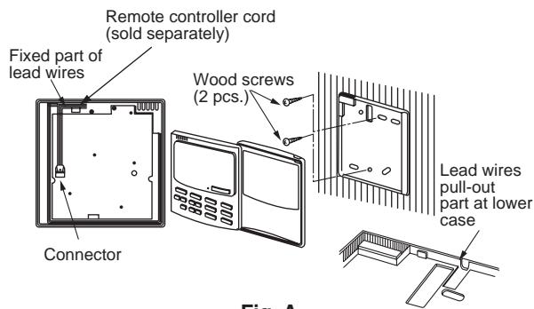
Fig. A
- For removal and mounting of the remote controller body and the rear case, refer to the item, "Using as concealed type".
- Remove the lead wires wound to the fixing part of lead wires of the remote controller body, remove the connectors, and then connect the remote controller cable (sold separately) to the connector section of the remote controller body. Insert the remote controller cable into the groove and form it, and wind it around the fixing part of lead wires.
Notching the lower case (thin part of the upper center part) with nipper, etc., pull out the remote controller cables from this part. (Fig. A) (Refer to the item, "How to perform cabling of the remote controller".)
Connect cables of the remote controller after check of terminal No. of the indoor unit so that there is no miswiring. (Do not apply AC 200/230/240V to the remote controller.)
- Fix the remote controller body by two wood screws.
- Using the cable clips (Accessory of remote controller cable sold separately), fix the remote controller cable to the wall surface.
How to perform cabling of the remote controller
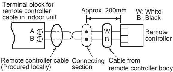
Connection diagram
Non polarity, 2 core cable is used. Use 0.5mm^2 to 2mm^2 cable.
| Attached wire joint (White, 2 pcs.) | Remote controller cable Cable from remote controller body Wire joint 1) Peel the sheath of the cable to be connected by approx. 14mm. 2) Twist two cables and pressure-connect them using a wire joint. 3) When an exclusive pressure-connecting tool is not used or soldering connection is used, apply insulation process with an insulation tape. |
For cabling of the remote controller, use the remote controller cable (sold separately).
- Remove the lead wires wound to the fixing part of lead wires of the remote controller body, remove the connectors, and then connect the remote controller cable (sold separately) to the connector section of the remote controller body. Insert the remote controller cable (sold separately) into the groove and form it, and wind it around the fixing part of lead wires.
- When using the remote controller cable (sold separately), refer to the Installation Manual attached to the remote controller cable.
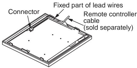
Requirement for installation of multiple remote controllers
"2 remote controllers" means that one or multiple units are operated by the multiple remote controllers.
(Max. 2 remote controllers can be set.)
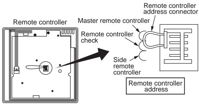
How to install
For 2 remote controllers, install the remote controllers in the following procedure.
- Set one of two remote controllers as the master remote controller. (At shipment from factory)
- For the other remote controller, exchange the remote controller address connector of the master to side remote controller on the P.C. board. Under this condition, the other remote controller functions as the side controller.
Basic wiring diagram
NOTE :
Connect cables without miswiring.
(Miswiring breaks the unit.)
In a case to operate an indoor unit from the remote controllers at two positions
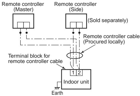
In a case to operate a group control of multiple indoor units from the remote controllers at two positions
*Master and Side remote controllers are operable even if they are installed to any indoor unit.
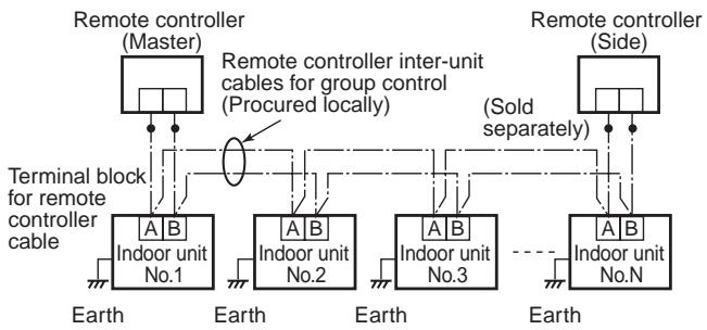
Remote controller test run setup
- When the remote controller is used at the first time, it accepts an operation approx. 5 minutes after the power supply has been turned on. It is not a trouble, but is because the setup of the remote controller is being checked.
- Push key after [TEST] has been displayed on LCD by keeping button on the remote controller for 4 seconds or more.
During the test run, [TEST] is displayed on LCD.
The temperature cannot be controlled if [TEST] is displayed.
Do not use [TEST] in a case other than a test run, otherwise an excessive load is applied on the machine.
- Use [TEST] in one of HEAT, COOL, and FAN operation modes.
NOTE : The outdoor unit does not operate for approx. 3 minutes after the power supply has been turned on or the operation has stopped.
- After the test run has finished, push button again to check [TEST] on LCD has gone off.
(For this remote controller, a release function of 60 minutes timer is provided to prevent continuous test runs.)
Wired remote controller (RBC-AMT21E)
Parts Name of Remote Controller
Display section
In the display example, all indicators are displayed for the explanation.
In reality only, the selected contents are indicated.
- When turning on the leak breaker at the first time, [SET DATA] flashes on the display part of the remote controller. While this display is flashing, the model is being automatically confirmed. Accordingly, wait for a while after [SET DATA] display has disappeared, and then use the remote controller.
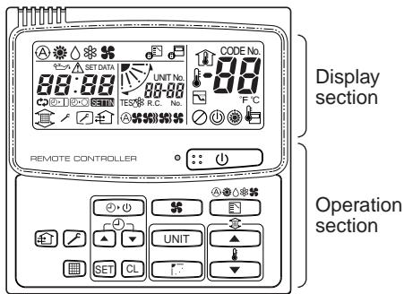
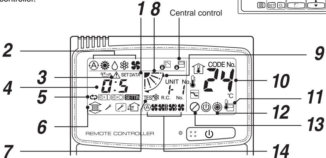
1 SET DATA display
Displayed during setup of the timer.
2 Operation mode select display
The selected operation mode is displayed.
[AUTO] mode is displayed on heat recovery type only.
3 CHECK display
Displayed while the protective device works or a trouble occurs.
4 Timer time display
Time of the timer is displayed. (When a trouble occurs, the check code is displayed.)
5 Timer SETIN setup display
When pushing the Timer SETIN button, the display of the timer is selected in order of [OFF]
→ [OFF] repeat OFF timer → [ON]
No display.
6 Filter display
If "FILTER" is displayed, clean the air filter.
7 TEST run display
Displayed during a test run.
8 Flap position display
(for 4-Way Air Discharge Cassette Type and Under Ceiling Type model only)
Displays flap position.
9 SWING display
Displayed during up/down movement of the flap.
10 Set up temperature display
The selected set up temp. is displayed.
11 Remote controller sensor display
Displayed while the sensor of the remote controller is used.
12 PRE-HEAT display
Displayed when the heating operation starts or defrost operation is carried out.
While this indication is displayed, the indoor fan stops or the mode enters in LOW.
13 Operation ready display
Displayed when cooling operation is unavailable because heating operation is performed.
14 No function display
Displayed if there is no function even if the button is pushed.
15 Air volume select display
The selected air volume mode is displayed.
(AUTO)

(HIGH)

(MED.) (LOW)

(LOW)

In the Concealed Duct High Static Pressure type models, [HIGH] only is displayed for the air speed.
Operation section
Push each button to select a desired operation.
This remote controller can operate the maximum 8 indoor units.
- The details of the operation needs to be set up once, afterward, the air conditioner can be used by pushing button only.
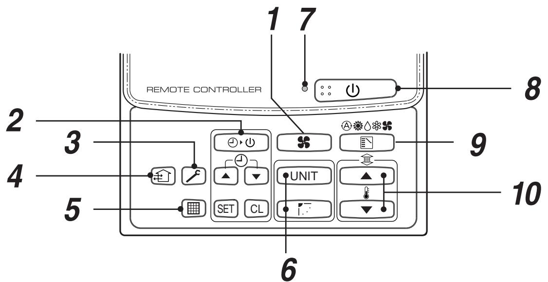
1 Air volume select button
Selects the desired air volume mode.
The Concealed Duct High Static Pressure type models cannot be operated.
2 Timer set button
TIMER SET button is used when the timer is set up.
3 Check button
The CHECK button is used for the check operation. During normal operation, do not use this button.
4 Fan button
FAN button is used when a fan which is sold on the market or etc. is connected.
- If is displayed on the remote controller when pushing the FAN button, a fan is not connected.
5 Filter reset button
Reset (Erases) "FILTER" display.
6 UNIT and AUTO flap button
UNIT
If the multiple indoor units are operated by only one remote controller, select the units when the air direction is adjusted.
:
Set up the auto swing and angle of the flap.
- This function is not provided to Concealed Duct Standard Type, High Static Pressure Type, Floor standing Cabinet Type, of Floor Standing Concealed Type.
7 Operation lamp
Lamp is lit during the operation. Lamp is off when stopped.
Although it flashes when operating the protection device or abnormal time.
8 button
When the button is pushed, the operation starts, and it stops by pushing the button again.
When the operation has stopped, the operation lamp and all the displays disappear.
9 Operation select button
Selects desired operation mode.
10 Set up temperature button
Adjusts the room temperature.
Set the desired set temperature by pushing
OPTION :
Remote controller sensor
Usually the TEMP. sensor of the indoor unit senses the temperature. The temperature on the surrounding of the remote controller can also be sensed.
For details, contact the dealer from which you have purchased the air conditioner.
- In case that one remote controller controls the multiple indoor units, the setup operation is unavailable in group control.
Correct Usage
When you use the air conditioner for the first time or when you change the SET DATA value, follow the procedure below. From the next time, the operation displayed on the remote controller will start by pushing the
button only.
Preparation
Turn on the main power switch and/or the leakage breaker.
- When the power supply is turned on, a partition line is displayed on the display part of the remote controller.
- After the power supply is turned on, the remote controller does not accept an operation for approx. 1 minute, but it is not a failure.
REQUIREMENT
- While using the air conditioner, operate it only with button without turning off the main power switch and the leak breaker.
- Do not turn off the leak breaker while the air conditioner is used.
- Turn on the leak breaker 12 hours or more before start of operation after the air conditioner has stopped for a long time.
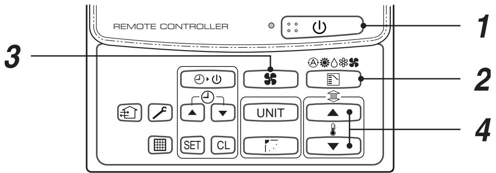
1 Push 山\ 山 button.
The operation lamp goes on, and the operation starts.
2 Select an operation mode with the "” button.
One push of the button, and the display changes in the order shown on the right.
- This function is not provided to Concealed Duct High Static Pressure Type.
3 Select air volume with "FAN" button.
One push of the button, and the display changes in the order shown on the right.
- When air volume is "AUTO A", air volume differs according to the room temperature.
- In DRY mode, "AUTO" is displayed and the air volume is LOW.
- In heating operation, if the room temperature is not heated sufficiently with VOLUME "LOW" operation, select "MED." or "HIGH" operation.
- The temperature which the temperature sensor detects is one near the air inlet of the indoor unit. Therefore it slightly differs from the room temperature according to the installation status. The setup value is a criterion of the room temperature. (Automatic air speed cannot be selected in FAN mode.)
- Air volume of function is not provided to "Concealed Duct High Static Pressure Type" but air speed "HIGH" only is displayed.
4 Determine the set up temperature by pushing the “TEMP. ” or “TEMP. ” button.
Stop
Push button.
The operation lamp goes off, and the operation stops.
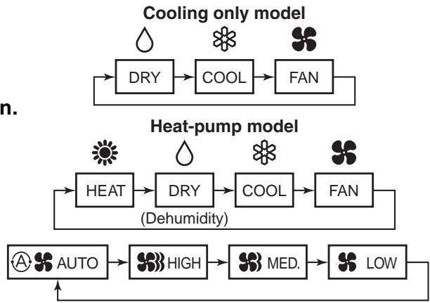
4-1-2 Simple remote controller (RBC-AS21E)
Accessory parts
| Part Name | Q'ty | Part Name | Q'ty |
| Remote controller (200mm-cable attached) | 1 | Spacer | 2 |
| Wire joint | 2 | ||
| Screw M4 x 25 | 2 | Clamper | 1 |
| Wood screw | 2 | Installation Manual | 1 |
Requirement to install the remote controller
Installation place
Install the remote controller at a position within 1 to 1.5m from the floor, where the average temperature in the room can be felt.
Do not install the remote controller at a place exposed to direct sunlight or direct outside air, such as a side of window, etc.
Do not install the remote controller at a place behind something or rear side of something, where air flow is poor in the room.
Do not install the remote controller in the freezing box or refrigerator because water proof or dropproof is not applied to this remote controller.
Be sure to set the remote controller vertically on the wall surface, etc.
How to select the room temp. sensor
The room temperature sensors are equipped in the indoor unit and the remote controller.
One of two sensors works. Usually, the room temperature sensor in the indoor unit is set to work. To select the sensor in the remote controller, turn the remote controller sensor from OFF to ON.
NOTE 1 :
Selecting the sensor in the remote controller is impossible on the side remote controller.
NOTE 2 :
Do not select the sensor in the remote controller when a remote controller sensor is used. (Because it causes a straying.)

How to install the remote controller switch
NOTE 1:
Avoid to twist the remote controller cable with the power supply cable, etc. or to store them in the same metal pipe, otherwise it causes a malfunction.
NOTE 2 :
Install the remote controller apart from the generation source of noise.
NOTE 3 :
When noise is contained to the power source of the indoor unit, counter measures such as mounting the noise filter is necessary.
In case of using the remote controller as a concealed type
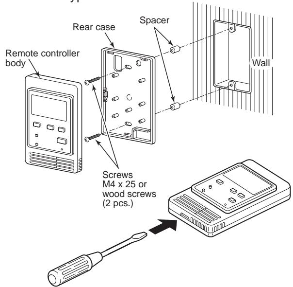
- Inserting a minus screwdriver, etc. into the groove at the lower side of the remote controller body, force open the rear case to remove it.
- Using the attached M4 screws (2 pcs.), fix the rear case of the remote controller. Before installation, press to open the screw hole with a screwdriver, etc.
Fix it with the spacer, but not so strongly. If the remote controller does not fit closely to the wall, adjust it by cutting off the spacer.
- Connect the remote controller cable (2 cores) to the cable from the remote controller body. Connect the remote controller cable without miswiring upon confirmation of the terminal numbers of the indoor unit. (If applied AC 220/230/240V, may damage the unit.)
- Install the remote controller body to hooks on the rear case and putting into the hooks.
How to perform cabling of the remote controller
Connection diagram
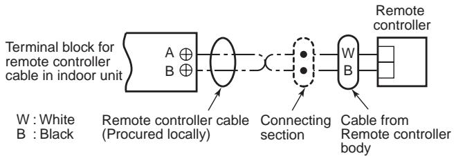
- Non polarity, 2 core cable is used.
Use 0.5mm^2 to 2mm^2 cable.
| Attached wire joint (White, 2 pcs.) | Remote controller cable Cable from remote controller body Wire joint |
| 1) Peel the sheath of cable to be connected by approx. 14mm. 2) Twist two cables and pressure-connect them using a wire joint. 3) When an exclusive pressure-connecting tool is not used or soldering connection is used, apply insulation process with an insulation tape. |
Requirement for installation of multiple remote controllers
"2 remote controller control" means that one or multiple units are operated by the multiple remote controllers.
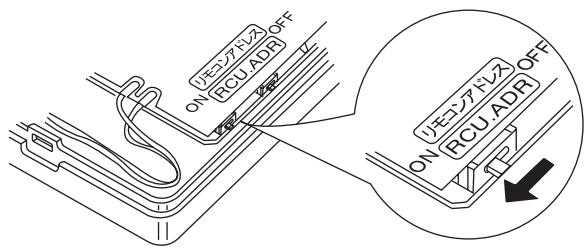
How to install
For 2 remote controller control, install the remote controllers in the following procedure.
- Set one of the set multiple remote controllers to the master remote controller. (At shipment from factory)
- For other remote controllers, turn the remote controller address switch on the remote controller P.C. board from OFF to ON. They function as side remote controllers under the above condition.
- Basic cabling diagram
NOTE :
Connect cables without miswiring. (Miswiring breaks the unit.)
In a case to operate an indoor unit from the remote controllers at two positions
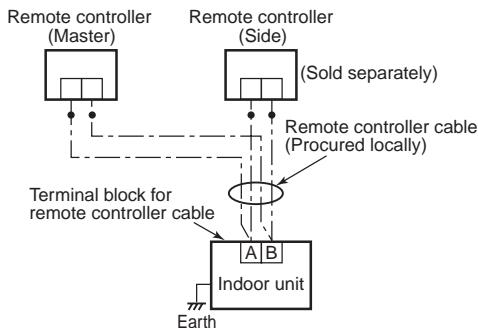
In a case to operate a group control of multiple indoor units from the remote controllers at two positions
- Master and side remote controllers are operable even if they are installed to any indoor unit.
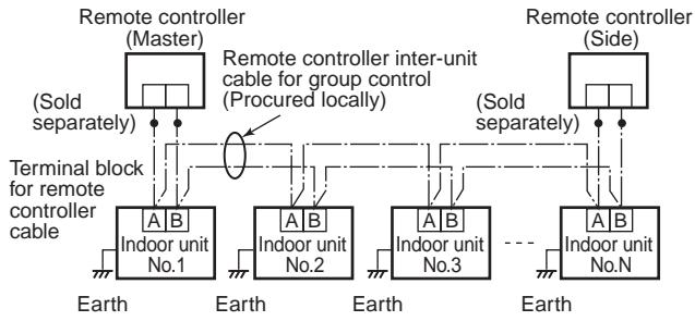
Remote controller test run setup
- Push key after keeping [CHECK] button pushed on the remote controller for 4 seconds or more.
During the test run, "TEST" is displayed on LCD.
The temperature cannot be controlled if [TEST] is displayed. Do not use [TEST] in a case other than a test run, otherwise an excessive load is applied on the machine.
- Use [TEST] in one of HEAT, COOL, and FAN operation modes.
NOTE :
The outdoor unit does not operate for approx. 3 minutes after the power supply has been turned on or the operation has stopped.
- After the test run has finished, push [CHECK] button again to check "TEST" on LCD has gone off. (For this remote controller, a release function of 60 minutes timer is provided to prevent consecutive test runs.)
NAME AND OPERATION
- For Cooling Only type, , and are not displayed on LCD.
- Max. 8 indoor units can be operated by a remote controller.
- Once setting the operation items, you can operate the previous condition by pushing button only.
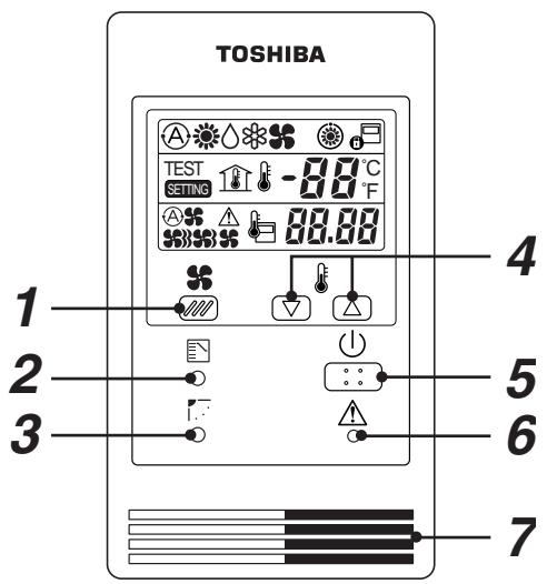
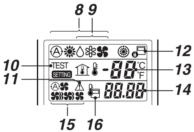
1 Fan Speed button
2 Operation mode button
3 Swing/Air direction button The flap angle is changed.
4 Temperature Setup button Every pushing button, temperature rises by 1^ Every pushing button, temperature decrease by 1^
5 (1) [Start/Stop] button
6 Check button (Used in servicing) - Do not use this button usually.
7 Remote control temperature sensor Usually controlled by the indoor unit sensor, it can be changed to the remote controller. For details, contact the shop which you purchased the air conditioner. (When using a group control method, do not use the remote controller sensor.)
8 Selected mode displays (Heat pump type) Any one of , or displayed. While is displayed, the indoor fan stops or the mode is Low speed mode. [AUTO] mode is displayed on heat recovery type only.
9 Selected mode displays (Cooling only type)
Any one of , 或 is displayed.
10 TEST is displayed during Test Run.
11 (CHECK) is displayed when the protective device worked or trouble occurred.
12 is displayed during the operation.
If the remote controller setting is prohibited by the central remote controller, e flashes when [Start/Stop], [Operation Select] or [Temp. Setup] button is pushed and change is not accepted.
13 The setup temperature is displayed.
14 Warning code is displayed when a trouble occurred.
15 Selected fan speed, (\text{串串串串串串串串串串串串串串串串串串串串串串串串串串串串串串串串串串串串串串串串串串串串串串串串串串串串串串串串串串串串串串串串串串串串串串串串串串串串串串串串串串串串串串串串串串串串串串串串串串串串
16 is displayed when the remote controller sensor is used.
COOL/HEAT AUTO, HEAT, DRY, COOL, FAN
1 Power supply
Turn on the power supply of the air conditioner 12 hours before starting the operation.
2 Push button.
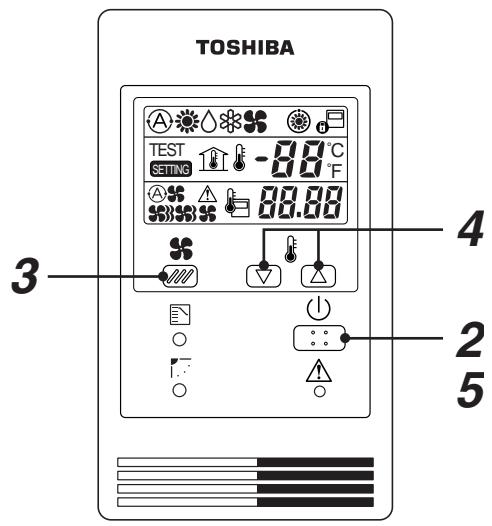
3 Push button (M) to select fan speed.
When selecting AUTO, fan speed is automatically changed.
(During FAN mode, the air speed is not.)
4 Push either or set to Auto.
- During FAN mode, the temperature cannot be set up.
5 Stop
Push () button.
When stopping the unit by the remote controller, the fan of the outdoor unit, the fan or the outdoor unit may keep operating for a while even if the compressor of the outdoor unit has stopped.
- When the unit cannot be stopped by the remote controller.
Turn off the main power switch or the leakage breaker, and then contact the shop which you purchased the unit.
- In heating, if the room is not enough heated with FAN , select FAN or .
- As the temperature sensed by the temp. sensor periphery of the suction port of the indoor unit, it differs from in the room according to the installation state. Set the temperature considering the setup value as the standard temperature in the room.
Automatic Cool/Heat
When all indoor units in the identical refrigerant system are controlled as a group and when all indoor units are installed in the same room, the cooling or heating operation is automatically performed with the difference between the setup temperature and the room temperature.
4-1-3 Wireless remote controller kit (1) TCB-AX21U (W)-E
Accessory parts
| Part Name | Q'ty | Part Name | Q'ty |
| Sensor unit | 1 | Battery | 2 |
| Owner's Manual | 1 | ||
| Tapping screw M4 x 16mm | 2 | ||
| Remote controller | 1 | Clamper | 1 |
| Remote controller holder | 1 | Fixing screw M4 x 12mm | 1 |
How to set the fan motor speed refer to the OWNER'S MANUAL
How to install the sensors
- The positions where the sensors can be installed are limited to the corners (A) in Fig. 1. Therefore, for installation of the sensor units, consider the direction when a panel is installed to the indoor unit.
- Remove the suction grille.
- Take off the screw fixing the corner cap and remove the corner cap sliding it side-ward. (Fig. 2)
Fig. 1
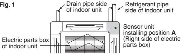
Ceiling panel
Fig. 2
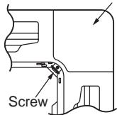
Corner cap
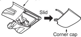
- The thermal insulation material is stuffed in the square hole provided to pass through cables of the panel, so take off it once and pass the cable out of the sensor of wireless remote controller through the grille. Using a clamp, fix the cable with screws and then be sure to stuff again the removed thermal insulation material as original. (Fig. 3)
If the thermal insulation material is not stuffed, dewing may happen.
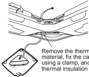
Fig. 3
Remove the thermal insulation material, fix the cable with screws using a clamp, and put in the thermal insulation material again.
- After cabling according to "How to perform cabling of sensor units", remain the cable length enough to remove the sensor unit and fix it with screws using a clamp. (Fig. 3)
- Install the sensor units to the panel. In this time, slide the panel so that the hooks are fit in completely at 3 positions. And also be careful not to pinch the cable. (Fig. 4)
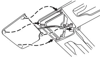
Fig. 4
NOTES :
- Avoid to twist the cables of the operation section with cables of the power supply, etc. It causes a malfunction.
- When noise is contained to the power supply of the indoor unit, counter measures such as mounting the noise filter is necessary.
How to perform cabling of sensor units
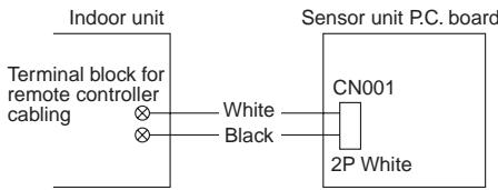
Connection diagram
Connection
Connect the cables out of the sensor unit to the terminal block for remote controller cabling of the indoor unit. (There is no polarity.)
Requirement
The control by two remote controllers is enabled by installing the wireless remote controller with the wired remote controller for an indoor unit.
(Max. 2 remote controllers of wireless or wired are installable.) "2-remote controllers" controlling means that one or multiple units are operated by the multiple remote controllers.
NOTES :
- Upon confirmation of the terminal numbers of the indoor unit, connect the remote controller cables without miscabling. (If applied AC 220/230/240 Volt, damage the unit.)
- The multiple wireless remote controller kits cannot concurrently be used for an indoor unit.
- When installing simultaneously the wireless remote controller with the wired remote controller, set one of them as the side remote controller.
- When setting the wired remote controller as the side, exchange the address connector at the rear of P.C. board of wired remote controller from master to side remote controller.
- When setting the wireless remote controller as the side, turn No.3 of DIP switch [S003] on P.C. board of wireless remote controller sensor unit from OFF to ON.
To operate an indoor unit by 2 remote controllers
- The indoor unit is operated if either wireless or wired remote controller is set as master or side remote controller. (Total cable length: Within 400m)
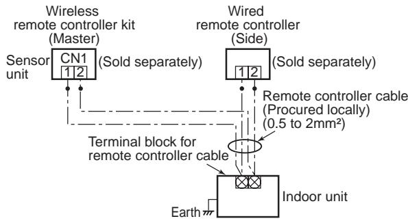
To operate a group control of multiple indoor units by 2 remote controllers
- Master and Sub remote controllers are operable even if they are installed to any indoor unit. (Total cable length: Within 200m)

How to set the room temperature sensor
The room temperature sensors are equipped in the indoor unit and the wireless remote controller. One of two sensors works.
The room temperature sensor is set to the indoor unit side at the shipment from the factory. To select the sensor in the remote controller, push the SENSOR button (Right figure) inside of the remote controller cover and check "Main sensor" disappears from
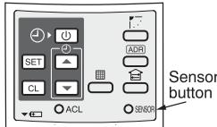
LCD.
NOTE :
If the room temperature data from the remote controller is not transmitted to the unit for 10 minutes or more, the sensor at indoor unit side is automatically selected even if the sensor at the remote controller side is selected. Fix the remote controller toward the unit as possible.
How to set the address switch
When the multiple sensors are installed in the same room, an address can be set to prevent cross communication.
When replacing the battery and pushing SET button, the address of the remote controller becomes [ALL] and the sensor is enabled to receive signal regardless of setting of address switch of the operation section.
For selecting of the remote controller address, refer to Owner's Manual.
Change the address of the sensor by removing screws of P.C. board cover of the sensor unit. After then, fix the cover with screws using a clamp.
| Display of remote controller address | Address ALL | Address I | Address 2 | …… | Address 6 |
| Address switch position of sensor | * Address switch of sensor unit can be set any position. | S001 S002 | 4-6 1-3 Address Select Address | 4-6 1-3 Address Select Address | …… |
| S001 S002 | 4-6 1-3 Address Select Address | S001 S002 |
Slide switch
Check the slide switch in the battery box of the remote controller is set to [S] / [A] at shipment from the factory.
Do not change the setting.
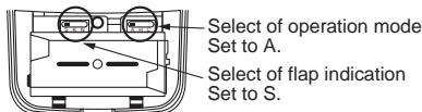
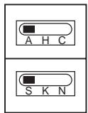
Self-diagnosis table and measures
| Lamp indication | Cause | Measures |
| No indication even if the remote controller is operated. | Power supply is not turned on. Miscabling between sensor unit and indoor unit | Check cable connection and correct it. |
| Defective connection between sensor unit and indoor unit | Lamp indication of sensor : Goes off Flash (0.5-sec. interval) | |
| Miscabling or defective connection between indoor and outdoor units | ||
| Flashes alternatively | Protective device of outdoor unit works. | Check outdoor unit. |
| Protective device of indoor unit works. | Check indoor unit. |
Test run
How to use [TEST]
-
Turn No.1 of DIP switch [S003] on sensor P.C. board from OFF to ON.
-
During the test run, all the indication lamps on LCD flash.
-
During the test run, the temperature cannot be controlled.
![TOSHIBA TCB-SC642TLE2 - How to use [TEST] - 1](/content/2025/01/121691/images/2501cd97cac75e658a7ce055a259b653007ca0edb15a34d590ccd62f5610a497.jpg)
How to handle the remote controller
In case using remote controller mounting to the wall, etc.
Check a signal is received correctly by pushing button at the position to be fixed.
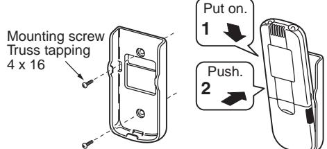
- To take off remote controller, pull it toward you.
Replacement of battery
- Holding the both ends of the cover and remove it by sliding downward.
- Correctly insert 2 AAA alkali batteries matching + and - polarities with indications.
- Push SET button with something tipped and attach the cover.
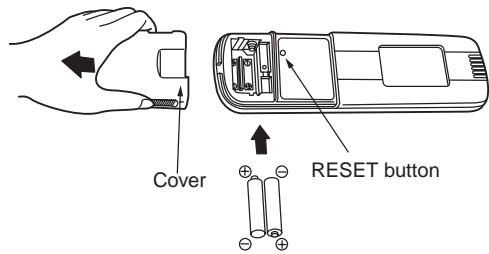
Cautions for installation of the remote controller
To operate the remote controller by fixing it to the wall, etc. with a remote controller holder, turn on the fluorescent lamp, operate the remote controller at the position to be fixed, check the air conditioner normally operates, and then mount it.
When the room temperature is sensed by the remote controller, mount the remote controller paying attention to the following items.
Place not exposed directly to cold or hot wind.
Place not exposed directly to the sunlight.
Other places where the remote controller is not influenced.
Explanation to customers
Hand over the "Owner's Manual" and "Installation Manuals" to the customer after installation works.
Explain usage and maintenance of the remote controller according to "Owner's Manual".
4-1-3 Wireless remote controller kit (2) (RBC-AX22CE)
Accessory parts
| No. | Accessory | Q'ty | No. | Accessory | Q'ty |
| 1 | Sensor unit | 1 | 4 | Battery | 2 |
| 2 | Remote controller | 1 | 5 | Owner's Manual | 1 |
| 3 | Remote controller holder | 1 | 6 | Truss tapping screw, 4 x16 | 2 |
Installation of sensor unit
- Open the suction grille, remove a screw, move the side panel toward you (direction of arrow), and then remove the side panel. (Fig. A)
- Lap the end of flat head screw driver with vinyl tape, and forcedly insert it into the groove at the side under circle mark on the cover. (Be careful not to damage the panel.) (Fig. B)
- Pass the lead wire through the panel, and install the sensor unit to the panel hole. (Projection of the sensor unit is fixed by the panel hole.)
- Fix the lead wire of the sensor to the cord clamp which fixes the cables of the louver motor. (Fig. C)
- Install the side panels.
-
Put the lead wire from the sensor unit along cables of the louver motor and others, and then fix it with the cord clamp. (Fig. D)
-
D raw in it using a hole at the upper side of the electric box.
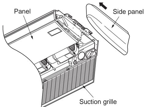
Fig. A
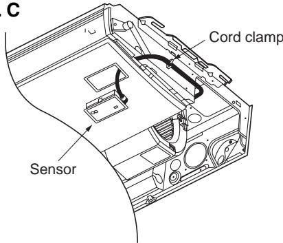
Fig. C
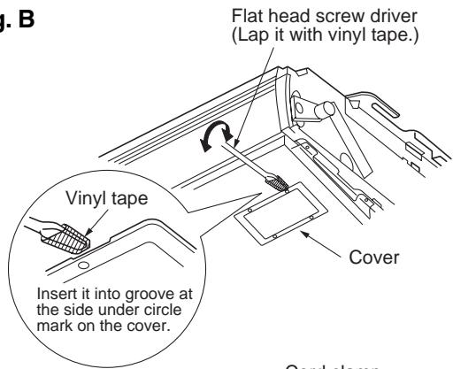
Fig. B
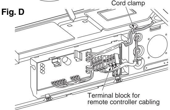
[NOTE 1]
Avoid to twist cables of the sensor with the power cables, otherwise a malfunction is caused.
*For cabling and test run, refer to "Cabling of sensor unit" of these sheets and "Test run" of the Installation Manual attached to the indoor unit.
How to perform cabling of sensor units
Connection diagram
Connection
- Connect the cables out of the sensor unit to the terminal block for remote controller cabling of the indoor unit. (There is no polarity.)
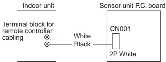
Requirement
The control by two remote controllers is enabled by installing the wireless remote controller with the wired remote controller for an indoor unit.
(Max. 2 remote controllers of wireless or wired are installable.)
"2-remote controllers" controlling means that one or multiple units are operated by the multiple remote controllers.
NOTES :
- Upon confirmation of the terminal numbers of the indoor unit, connect the remote controller cables without miscabling. (If applied AC 220-240 Volt, damage the unit.)
- The multiple wireless remote controller kits cannot concurrently be used for an indoor unit.
-
When installing simultaneously the wireless remote controller with the wired remote controller, set one of them as the side remote controller.
-
When setting the wired remote controller as the sub, exchange the address connector at the rear of P.C. board of wired remote controller from master to side remote controller.
- When setting the wireless remote controller as the side, turn No.3 of DIP switch [S003] on P.C. board of wireless remote controller sensor unit from OFF to ON.
To operate an indoor unit by 2 remote controllers
- The indoor unit is operated if either wireless or wired remote controller is set as master or sub remote controller. (Total cable length: Within 400m)
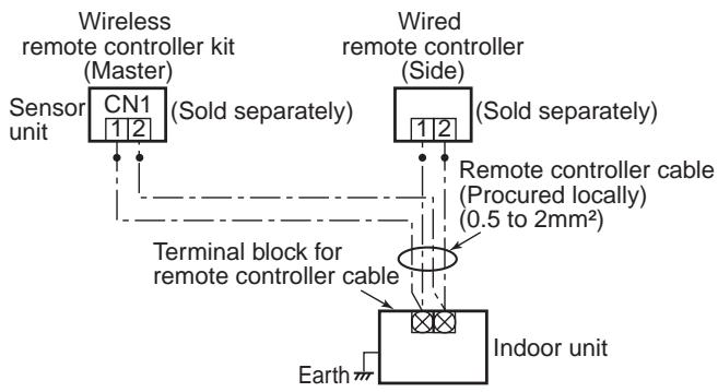
To operate a group control of multiple indoor units by 2 remote controllers
- Master and side remote controllers are operable even if they are installed to any indoor unit. (Total cable length: Within 200m)
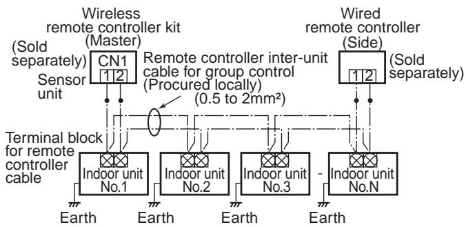
How to set the room temperature sensor
- The room temperature sensors are equipped in the indoor unit and the wireless remote controller. One of two sensors works.
- The room temperature sensor is set to the indoor unit side at the shipment from the factory. To select the sensor in the remote controller, push the SENSOR button (Right figure) inside of the remote controller cover and check "Main sensor" disappears from LCD.
NOTE:
If the room temperature data from the remote controller is not transmitted to the unit for 10 minutes or more, the sensor at indoor unit side is automatically selected even if the sensor at the remote controller side is selected.
Fix the remote controller toward the unit as possible.
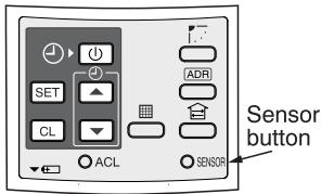
How to set the address switch
- When the multiple sensors are installed in the same room, an address can be set to prevent cross communication.
- When replacing the battery and pushing SET button, the address of the remote controller becomes [ALL] and the sensor is enabled to receive signal regardless of setting of address switch of the operation section.
- For selecting of the remote controller address, refer to Owner's Manual.
- Change the address of the sensor by removing screws of P.C. board cover of the sensor unit. After then, fix the cover with screws using a clamp.
| Display of remote controller address | Address ALL | Address 1 | Address 2 | ...... | Address 6 |
| Address switch position of sensor | * Address switch of sensor unit can be set any position. | S001 4-6 1-3 Address select | S001 4-6 1-3 Address select | ...... | 4-6 1-3 Address select |
| S002 3/6 5/4 Address | S002 3/6 5/4 Address | S001 3/6 5/4 Address |
Slide switch
- Check the slide switch in the battery box of the remote controller is set to [S] / [A] at shipment from the factory. Do not change the setting.
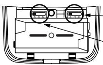
- Select of operation mode set to A.
Select of flap indication set to S.
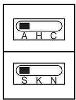
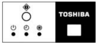
Lamp indication of sensor
: Goes off
:Flash
(0.5-sec. interval)
Self-diagnosis table and measures
| Lamp indication | Cause | Measures |
| No indication even if the remote controller is operated. | Power supply is not turned on. Miscabling between sensor unit and indoor unit | Check cable connection and correct it. |
| Defective con- nection between sensor unit and indoor unit | ||
| Miscabling or defective connec- tion between indoor and outdoor units | ||
| Flashes alternatively | Protective device of outdoor unit works. | Check outdoor unit. |
| Flashes alternatively | Protective device of indoor unit works. | Check indoor unit. |
How to set up filter sold separately of the high ceiling
- When the height of ceiling to be installed with a filter exceeds 3.5m or when installing a filter sold separately, tap-up of DC fan is required. Tap-up of DC fan can be set at No.2 (Tap 1) and No.4 (Tap 2) of DIP switch [S003] on the wireless sensor P.C. board. The wireless sensor P.C. board appears by removing screws at the rear side of the wireless sensor unit and the rear cover.
Setup for high ceiling
| [S003] No.2 (Tap 1) | [S003] No.4 (Tap 2) | Installable height of ceiling | |
| Standard (At shipment) | OFF | OFF | 3.5m |
| Type 1 | OFF | ON | 4.0m |
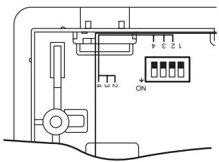
[S003] No.2 (Tap 1) and [S003] No.4 (Tap 2) are
| [S003] No.2 (Tap 1) | [S003] No.4 (Tap 2) | Filter sold separately | |
| Standard (At shipment) | OFF | OFF | Standard filter |
| Type 1 | OFF | ON | Optical regeneration deodorant filter |
| Type 3 | ON | OFF | High-performance filter |
| Type 6 | ON | ON | Deodorant filter / Ammonia deodorant filter |
[NOTE]
If the setup has been once performed, the set contents of Type 1, 3, and 6 can be arbitrarily changed. However, it is required to turn off [S003] No.2 (Tap 1) and No.4 (Tap 2) of DIP switch and also required to rewrite by the wired remote controller sold separately to return the set content to the standard one (at shipment). (For rewriting by a wired remote controller sold separately, refer to the Installation Manual attached to the indoor unit.)
Never set ON to DIP switch [S003] No.1 (Test run). (A test run is carried out on the remote controller.) (For the test run, refer to the Installation Manual attached to the indoor unit.)
Cautions for installation of the remote controller
- To operate the remote controller by fixing it to the wall, etc. with a remote controller holder, turn on the fluorescent lamp, operate the remote controller at the position to be fixed, check the air conditioner normally operates, and then mount it.
- When the room temperature is sensed by the remote controller, mount the remote controller paying attention to the following items.
- Place not exposed directly to cold or hot wind.
- Place not exposed directly to the sunlight.
- Other places where the remote controller is not influenced.
Explanation to customers
- Hand over the "Owner's Manual" and "Installation Manuals" to the customer after installation works.
- Explain usage and maintenance of the remote controller according to "Owner's Manual".
How to handle the remote controller
- In case using remote controller mounting to the wall, etc.
Check a signal is received correctly by pushing (1) button at the position to be fixed.
-
Replacement of battery
-
Holding the both ends of the cover and remove it by sliding downward.
- Correctly insert 2 AAA alkali batteries matching + and - polarities with indications.
- Push SET button with something tipped and attach the cover.
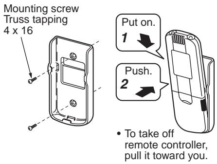
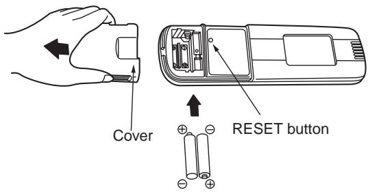
4-1-3 Wireless remote controller kit (3) (TCB-AX21E)
Accessory parts
| No. | Parts | Quantity | No. | Parts | Quantity |
| 1 | Separate receiver unit (provided 200mm power cable) | 1 | 6 | Spacer | 4 |
| 2 | Plate mounting | 1 | 7 | Wire joints | 2 |
| 3 | Screws M4 x 25 | 2 | 8 | Clamp | 1 |
| 4 | Screws M4 x 40 | 2 | 9 | Pattern template 95 x 51 | 1 |
| 5 | Wood screws | 2 |
Switch location of receiver unit
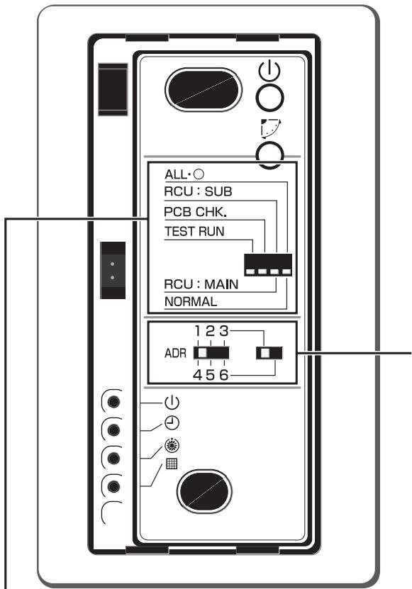
Address selector switch
This switch is used to address one of a maximum of six air conditioners that can be controlled by the remote controller.
All·O/NORMAL selector switch
Set this switch to the "NORMAL" position for the normal operation of the air conditioner. When this switch is set to the "ALL·○" position, the indoor unit of the air conditioner is turned off.
RCU:SUB/RCU:MAIN selector switch
Set this switch to the "RCU:MAIN" position for normal operation. Refer to page 7 for setting to the "RCU:SUB" position.
PCB CHK switch
This switch is not used and should be set in the position shown in the figure.
TEST RUN switch
This switch is used for test running.
Installation location of receiver unit
- Do not install in a location where the air contains oil mist, such as in a kitchen or factory.
- Do not install next to a window, or in any other location directly exposed to sunlight and outside air.
- Do not install nearby devices which can be expected to produce electrical noise, such as elevators, automatic doors, and industrial sewing machines.
- If the receiver unit is installed near a rapid-start type or inverter-type fluorescent lamp (a lamp which does not include a glow lamp), it may not be possible to receive the wireless remote controller signal in some cases. In order to prevent interference from fluorescent lamps, leave a minimum of 2 meters between the receiver unit and the fluorescent lamps, and install the receiver unit in a location where it can receive the wireless remote controller signal when the fluorescent lamps are lit.
How to install the receiver unit
NOTES :
- To avoid malfunction of the remote controller, do not assemble or run remote control wiring together with the power cables, and do not enclose them in the same metal conduit.
- When the power unit induces electrical noise, it is recommended that a noise filter or the like be installed.
For flush mounting into a wall, install the separate receiver unit in a metal switch box (field supply) that has been recessed into the wall in advance.
- Insert a flathead screwdriver or similar tool into the notch, and remove the face plate.
- Fix the receiver unit with 2 M4 screws provided. Do not overly tighten, and use the provided spacers. If the receiver unit does not fit in the wall, cut spacers to adjust the clearance.
- Connect the receiver unit wiring (2-core cable) with the cables extended from the indoor unit. (Refer to the section on receiver unit wiring.) Be sure to determine the correct terminal numbers on the indoor unit when wiring the receiver unit. The remote controller will be damaged if high voltage (such as 200 VAC) is applied.
- Reinstall the face plate.
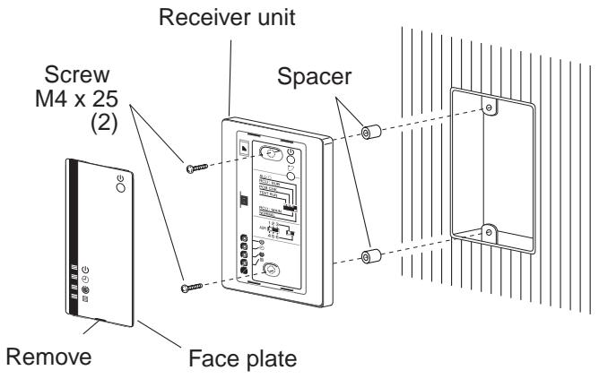
When using exposed mounting for the receiver unit, install onto a wall where the receiver unit can be attached.
- Insert a flathead screwdriver or similar tool into the groove on the bottom of the receiver unit. Pry open with the screwdriver and remove the lower case. (Fig. A).
- In order to later pass the receiver wiring out through the upper case (thin part at the top center), use nippers or a similar tool to cut a notch in the same size as the remote controller cord (optional). (Fig. B)
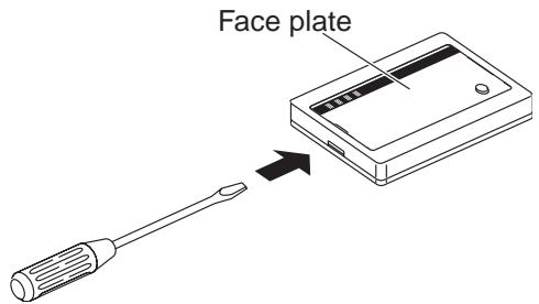
Fig.A
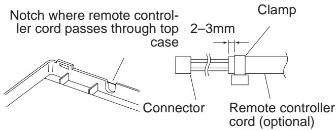
Fig.B
- Disconnect the wires that were connected to the connector at the time of shipment.
- Fasten the remote controller cord (optional) at the position shown in Fig. C, using the provided clampers. Then connect the cord to the receiver connector.
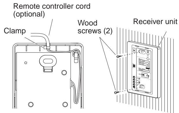
Fig.C
- Shape the remote controller cord as shown in Fig. C so that it fits at the top inside the receiver unit, above the PCB. Then attach the lower case. At this time, bend the head of the clamp so that it faces sideways.
- Remove the nameplate and use 2 wood screws to attach the receiver unit.
- Use the provided cord clips to fasten the remote controller cord to the wall.
- Reattach the nameplate.
If the separate receiver unit is installed on the ceiling, use the provided ceiling mounting bracket for installation.
- Insert a screwdriver or similar tool into the notch at the bottom to remove the receiver nameplate.
- Cut a section out of the ceiling along the provided paper pattern (95 x 51 mm).
- Pass the wire through the provided mounting bracket and insert the bracket into the installation hole. (Fig. D)
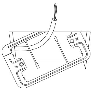
Fig.D
- Use bracket parts (A) and (B) to securely grip the ceiling material. (Fig. E)
- Connect the receiver wire (2-core) to the wire from the indoor unit. (Refer to "Wiring the Receiver Unit.") Check the terminal number on the indoor unit before wiring the receiver unit and be sure not to wire incorrectly. (The unit will be damaged if high voltage, such as 200 VAC, is applied.)
- Adjust the provided spacers so that they are several millimeters larger than the thickness of the ceiling material. Pass the 2 supplied screws (M4 x 40) through the spacers and tighten them enough to hold the receiver unit in place.
- Return parts (A) and (B) through the gap between the ceiling and receiver unit so that they are contained in the openings. Then tighten the screws. Do not tighten the screws excessively. This may result in damage or deformation of the case. Tighten to the point where the receiver unit can be moved slightly by hand. (Fig. F)

Fig.E
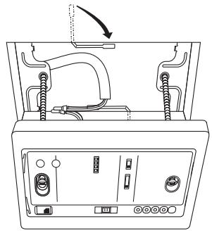
Fig.F
- Reattach the nameplate.
How to perform cabling of sensor unit
Flush Mounting
- Connection diagram
Indoor unit remote controller terminal board
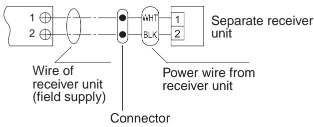
-
Provided wire joint (WHT 2)
-
Strip the insulation to approximately 14mm from the ends of the wires to be connected.
- Twist together the 2 wires and create a crimp connection at the wire joint.
- If a special crimping tool is not used, or if the connection is soldered, insulate the wires using insulation tape.
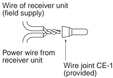
Exposed Mounting
Connection diagram
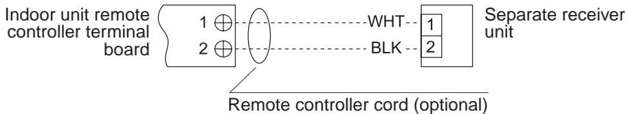
Requirement
The control by two remote controllers is enabled by installing the wireless remote controller with the wired remote controller for an indoor unit.
(Max. 2 remote controllers of wireless or wired are insatiable.)
"2-remote controllers" controlling means that one or multiple units are operated by the multiple remote controllers.
NOTES :
- Upon confirmation of the terminal numbers of the indoor unit, connect the remote controller cables without miscabling. (If applied AC 220-240 Volt, damage the unit.)
- The multiple wireless remote controller kits cannot concurrently be used for an indoor unit.
-
When installing simultaneously the wireless remote controller with the wired remote controller, set one of them as the side remote controller.
-
When setting the wired remote controller as the side, exchange the address connector at the rear of P.C. board of wired remote controller from master to side remote controller.
- When setting the wireless remote controller as the side, turn the switch of wireless remote controller receiver unit from RCU: MAIN to RCU:SUB.
To operate an indoor unit by 2 remote controllers
The indoor unit is operated if either wireless or wired remote controller is set as master or side remote controller.
(Total cable length: Within 400m)
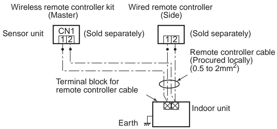
To operate a group control of multiple indoor units by 2 remote controllers
Master and Side remote controllers are open able even if they are installed to any indoor unit. (Total cable length: Within 200m)
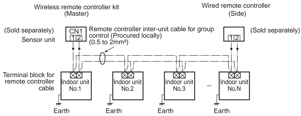
How to set the room temperature sensor
- The room temperature sensors are equipped in the indoor unit and the wireless remote controller. One of two sensors works.
- The room temperature sensor is set to the indoor unit side at the shipment from the factory. To select the sensor in the remote controller, push the SENSOR button (Right figure) inside of the remote controller cover and check "Main sensor" disappears from LCD.
NOTE :
If the room temperature data from the remote controller is not transmitted to the unit for 10 minutes or more, the sensor at indoor unit side is automatically selected even if the sensor at the remote controller side is selected.
Fix the remote controller toward the unit as possible.
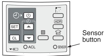
How to set the address switch
- When the multiple sensors are installed in the same room, an address can be set to prevent cross communication.
- When replacing the battery and pushing SET button, the address of the remote controller becomes [ALL] and the sensor is enabled to receive signal regardless of setting of address switch of the operation section.
- For selecting of the remote controller address, refer to Owner's Manual.
- Change the address of the sensor by removing screws of P.C. board cover of the sensor unit. After then, fix the cover with screws using a clamp.
| Display of remote controller address | Address ALL | Address 1 | Address 2 | Address 6 | |
| Address switch position of sensor | Address switch of sensor unit can be set any position. | 1 2 3 ADR 4 5 6 | 1 2 3 ADR 4 5 6 | 1 2 3 ADR 4 5 6 |
Wireless remote controller
Display Section
All indicators are shown in the right and the lower figures for the explanation.
Only selected contents are display in actual operation.
- When turning on the leakage breaker at the first time 3 minutes later, [SET DATA] flashes about for 1 minute on the display part of the remote controller. While this display is flashing, the model is being automatically confirmed.
Accordingly, wait for 1 minute after [SET DATA] display has disappeared, and then use the remote controller.
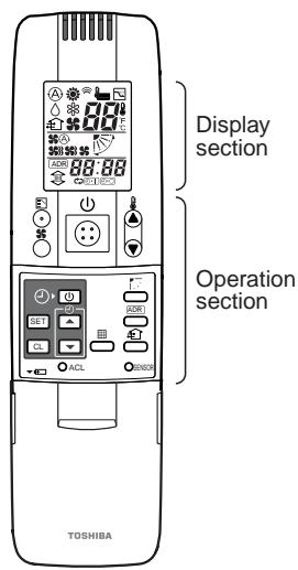
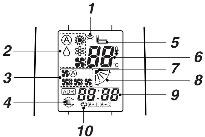
1 Transmitting indication
Displayed while operating the switches of the remote controller.
2 Mode display
The selected operation mode is displayed.
[A] [AUTO] mode is displayed on heat recovery type only.
3 Fan mode select display
The selected fan mode is displayed.
(AUTO)
(HIGH)
(MED.) $3
(LOW)
4 Filter display
If "FILTER" is displayed, clean the air filter.
5 CHECK display
Displayed while the protective device works or a trouble occurs.
6 Set up temperature display
The selected set up temp. is displayed.
7 Flap position display
8 SWING display
Displayed during up/down movement of the flap.
9 Timer time display
Time of the timer is displayed.
(When a trouble occurs, the check code is displayed.)
10 Timer SETIN setup display
When pushing the Timer SET button, the display of the timer is selected in order of [OFF] (, 1) [OFF] repeat OFF timer () [ON]
No display.
Operation Section
Push each button to select a desired operation.
- The details of the operation needs to be set up once, afterward, the air conditioner can be used by pushing (1) button only.
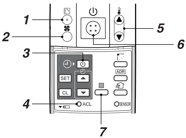
1 Operation select button
Selects desired operation mode.
2 Fan mode select button
Selects a fan mode.
3 Timer set button
TIMER SET button is used when the timer is set up.
4 Check button
CHECK button is used for check operation. During normal operation, do not use this button.
5 Temperature set button
Adjusts required room temperature.
Set required set temperature by pushing or .
6 Start/Stop button
When the button is pushed, operation starts, and it stops by pushing the button again.
When the operation stops, the operation lamp and all displays disappear.
7 Filter reset button
Resetss(Erases)“FILTER display.
OPTION :
Remote controller sensor
Usually the TEMP. sensor of the indoor unit measured a temperature. A temperature around the remote controller can also be measured.
For details, contact the dealer from which you have purchased the air conditioner.
Signal Receiving Part (TCB-AX21U(W)-E)
- The signal receiving part is mounted to the ceiling panel.
Signal Receiving Part
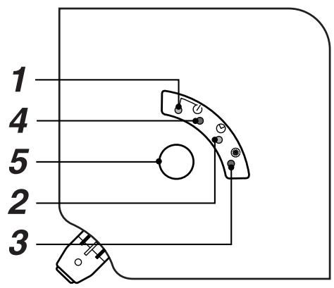
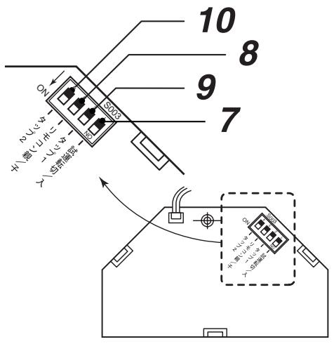
1 Emergency operation button
2 Signal receiving part
The signal sent from the remote controller is received.
3 Display lamp
One of displays flashed while a trouble occurs.
When the display lamp flashes, refer to "Before asking of repair".
4 lamp
This lamp goes on during operation.
5 lamp
This lamp goes on while the timer is reserved.
6 lamp
- In heating operation this lamp in the following cases;
The operation has started.
The temp. controller has worked.
The unit is under defrost operation.
- This lamp flashes while a trouble occurs.
7 Trial ON switch (S003-1)
This switch is not used in normal time, but used in trial operation time.
8 Master/Side remote controller switch (S003-3)
Use this switch at the position of [fSf, fRf" o(e (PRIORITY)]. This switch can be used together with the wired remote controller.
9 Fan speed change tap 1 (S003-2)
10 Fan speed change tap 2 (S003-4)
These switches are used to select DC motor speed of a 4-way cassette type indoor unit by the taps.
When installing an indoor unit to a high ceiling surface or when changing the number of discharge ports, perform setting referring to the next page.
11 Address switch
This switch distinguishes the signal, send or receive.
The following switches are provided to the rear side of the receiving part. For setup, contact the shop which you purchased the unit.
- If "pi, pi" sound is heard, the MODE lamp of the display lamp goes on, and the ① lamp and ⑧ lamp flash alternately, the operation is not performed with the desired mode.
Signal Receiving Part (RBC-AX22CE)
- The signal receiving part is mounted to the ceiling panel.
Signal Receiving Part
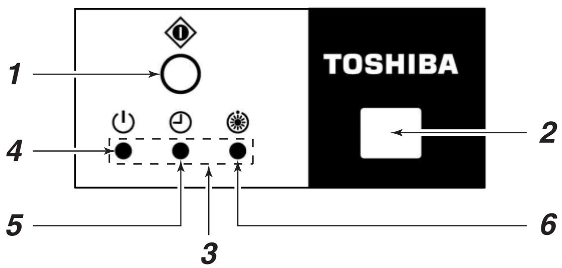
1 Temporary operation button
2 Signal receiving part
The signal sent from the remote controller is received.
3 Display lamp
One of displays flashed while a trouble occurs. When the display lamp flashes, refer to "Before asking of repair" in 13 page.
4 lamp
This lamp goes on during operation.
5 lamp
This lamp goes on while the timer is reserved.
6 lamp
- In heating operation this lamp in the following cases;
The operation has started.
The temp. controller has worked.
The unit is under defrost operation. -
This lamp flashes while a trouble occurs.
-
If "pi, pi" sound is heard, the MODE lamp of the display lamp goes on, and the lamp and lamp flash alternately, the operation is not performed with the desired mode.
Signal Receiving Part (TCB-AX21E)
- The signal receiving part is mounted to the ceiling panel.
Signal Receiving Part
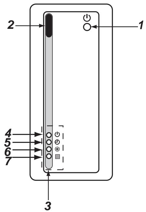
1 Temporary operation button
2 Signal receiving part
The signal sent from the remote controller is received.
3 Display lamp
One of displays flashed while a trouble occurs. When the display lamp flashes, refer to "Before asking of repair" in 95 page.
4 lamp This lamp goes on during operation.
5 lamp This lamp goes on while the timer is reserved.
6 lamp In heating operation this lamp in the following cases; The operation has started. The temp. controller has worked. The unit is under defrost operation.
- This lamp flashes while a trouble occurs.
7 lamp This lamp lights to indicate that it is time to clean the filter.
- If "pi, pi" sound is heard, the MODE lamp of the display lamp goes on, and the lamp and lamp flash alternately, the operation is not performed with the desired mode.
Cool/Heat AUTO, Heat, Dry, Cool, Fan
Power supply
Turn on the power of the wireless remote controller 12 hours before starting the operation.
- After the power supply has been turned on, the operation of the remote controller is not accepted for approx. 1 minute. It is not a failure.
(The sensor receives the signal once, but the received contents are cleared.)
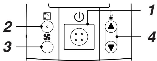
1 Push Start/Stop button.
2 Push (Operation Select button) operation to select one of 心 , 心 , 心 , and
3 Push (Fan Mode Select button) to select one of fan speed modes.
When selecting , the fan speed is automatically changed.
(During FAN mode, the air speed is not automatically changed.)
4 Push either or to select the desired temperature.
- During FAN mode, the temperature cannot be set up.
5 Stop
Push Start/Stop button.
When using the remote controller to stop the unit, the outdoor unit fan may keep operating for a while even if the compressor of the outdoor unit has stopped.
- In heating operation, if the room is not comfortably heated with FAN , select FAN or .
Although they are displayed, the function may not be provided according to the used indoor unit. (Fan speed is constant.)
- When the unit cannot be stopped by the normal operation
Turn off the power switch or leakage breaker, and then contact the shop which you purchased the unit.
Automatic cool/heat
When all indoor units in the identical refrigerant system are controlled as a group, the cooling/heating operation is automatically performed with the difference between the setup temperature and the room temperature.
Dry operation
- There is no dry function according to the used indoor unit even if DRY is displayed on the display section of the remote controller. (Same to Cooling operation)
- When the room temperature approaches the setup temperature, running/stop operations are automatically repeated.
- In order not to return humidity to the room as possible, the mode of indoor fan enters LOW mode when the operation has stopped.
- The fan speed cannot be adjusted according to the used indoor unit or status of the room temperature.
- The DRY mode cannot be used according to the used indoor unit when the outdoor temperature is 15^ or lower.
- After setting of the timer, set the remote controller at a position where the signal can reach the sensors (indoor unit body).
(The signal of the timer operation is sent from the remote controller.) - Set up the timer during display of the operation mode.
| Use in the following cases | During display |
| To stop the air conditioner after the previously set time has passed | ◇→◇ |
| To stop the air conditioner every time after the previously set time has passed | →◇→◇ |
| To operate the air conditioner after the previously set time has passed | ◇→◇ |
How to use OFF timer
(Ex.)To stop the unit 30 minutes after
1 When pushing the timer SET once, · and the time flash on the remote controller.
2 Push TIME or to set the time to 0.5.
3 Push SET and the go on timer.
How to use the repeat timer
(Ex.)To stop the air conditioner every time after 2.5 hours has passed
1 When pushing the timer SET twice, C3, ② and the time flash on the remote controller.
2 Push TIME or to set the time to 2.5.
3 Push SET and the 心 _ 1 go on timer.
The works, and the operation stops after 2.5 hours. When pushing (Start/Stop) button again to operate the unit, the operation stops after 2.5 hours.
How to use ON timer
(Ex.)To operate the unit 8 hours after
1 When pushing the timer SET three times, 4 and the timer flash on the remote controller.
2 Push TIME or to set the time to 8.0.
3 Push SET
The operation mode displays disappears, and then time and the go on.
To stop the timer operation
To stop the timer operation
Push CL button. Then the timer display disappears.
HOW TO ADJUST AIR DIRECTION
- Never move the flap (Air direction up/down adjusting plate) which is operated on the remote controller with hands except a case of cleaning of the flap.
- While the unit stops, the flap (Air direction up/down adjusting plate) directs downward automatically.
- During preparation of heating, the flap (Air direction up/down adjusting plate) directs upward. The swinging operation starts after heating preparation status has been cleared. However, swinging is displayed on the AUTO flap display of the remote controller even if the heating operation is being prepared.
How to set up the air direction
Every pushing button during operation, the air direction changes.
How to start swinging
When pushing button, set the direction of the flap (Air direction up/down adjusting plate) to the lowest position, and then push button again, the swinging is displayed and the air direction automatically changes upward/ downward.
How to stop swinging
Pushing ^- button once again during swinging of the flap stops the flap at the desired position.
Then, when pushing ^- button, the air direction can be set to position from the uppermost position.
- In cooling or dry operation, the flap does not stop when the flap directs downward.
If doing so, the flap stops at the 3^rd position from the uppermost position.
In heating operation
Direct the flap (Air direction up/down adjusting plate) downward, otherwise the hot air may not reach at the foot.
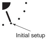
In cooling/dry operation
Direct the flap (Air direction up/down adjusting plate) upward, otherwise dewdrops may adhere or drip down to near of the discharge grille.
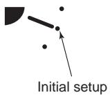
In air blowing operation
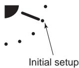
In all operation modes

Display when swinging stopped


Fan/Heat operation
Cool/Dry operation
SLIDE SWITCH
- Do not change setting of the slide switch because a malfunction occurs by other settings.
- Before usage, check the slide switch is set to the position as follows;
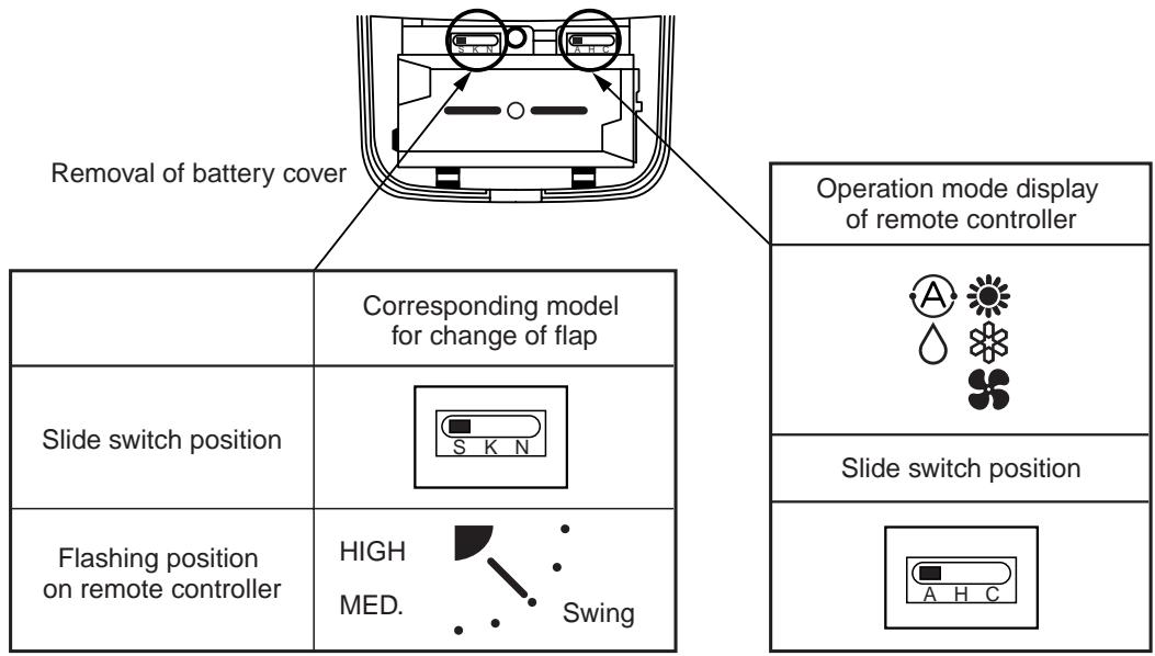
HOW TO INSERT THE BATTERIES
- Holding the both sides of the cover and remove it by sliding downward.
- Correctly insert 2 AAA alkali batteries matching + and - polarities with indications.
-
Push RESET button with something tipped and attach the cover.
-
Replace the batteries when the display section of the remote controller is difficult to be read, or when the signal cannot be sent if you are not close to the sensor.
(The standard replacement time of the alkali batteries is approx. one year.) - Use the same type of new batteries for replacing two batteries.
- In case when you do not the remote controller for a long time, remove the batteries.
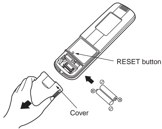
ADDRESS
When the multiple indoor units corresponding to the wireless remote controller are installed in the same room, an address can be set up to prevent an interference.
Matching the address switch of the sensor with number of the remote controller address, Max. 6 indoor units can be controlled by the corresponding remote controller individually.
The address switch for receiving the signal is prepared to the sensor (inside of panel or indoor unit) and the address switch for sending the signal is prepared to the remote controller. For details, contact the shop which you purchased the air conditioner.
How to Check the Address
When pushing ADR button on the remote controller, the present address is displayed on the display section of the remote controller. If this address matches with the address of the sensor (inside of panel or indoor unit), a buzzer sounds.
(When ALL is displayed, buzzer sound is necessarily heard.)
When ALL is displayed, the air conditioner can be operated regardless of any address of the sensor (inside of the indoor unit). Send the signal by directing the remote controller toward the sensor (panel or indoor unit body) to be handled.
How to Match the Address
Setup to remote controller address
- When keeping pushed for 4 seconds or more, lamp goes on at the display section of the remote controller and the present address is displayed with flashing.
- Every pushing , the address is exchanged as ALL 1 2 3 6 ALL. Match one of them with the address switch of the indoor unit sensor to be handled.
- When pushing _L , the address display goes on and is displayed for 5 seconds. If the address matches with the address switch of the operation part, the buzzer sounds.
| Display of remote controller address | Address ALL | Address 1 | Address 2 | …… | Address 6 |
| Address switch position of sensor | * Address switch of sensor unit can be set any position. | S001 4-6 1-3 S002 6 5 2 4 Address | S001 4-6 1-3 S002 6 5 2 4 Address | …… | S001 4-6 1-3 S002 6 5 2 4 Address |
Turn the knob to the right side for 1 to 3 while to the left side for 4 to 6 of Address select switch S001.
Emergency Operation (TCB-AX21U(W)-E)
HOW TO PERFORM EMERGENCY OPERATION
In the following cases, operate the air conditioner in emergency by emergency operation of the operation part (inside of panel or indoor unit).
- The battery in the remote controller expired.
- A trouble occurred on the remote controller.
- The remote controller have disappeared.
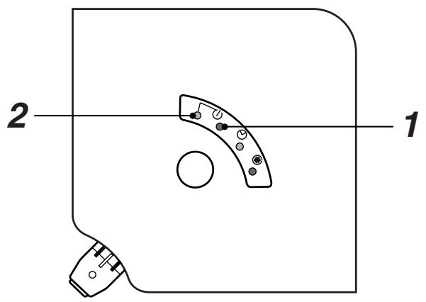
1 Start
Push emergency operation.
(If starting the operation when the room temperature is 24^ or higher, the mode enters COOL mode. If starting the operation when the room temperature is 24^ or lower, the mode enters HEAT mode.)
2 Stop
Push emergency operation once more.
CAUTION
- The ON switch of the test run and the ON switch of the test are used for the test run mode in the installation time. Do not use them in the normal time.
- If the "all stop" is selected in the normal/all stop switches, a signal from the remote controller is not accepted.
Emergency Operation (RBC-AX22CE)
HOW TO PERFORM TEMPORARY OPERATION
In the following cases, operate the air conditioner in emergency by emergency operation of the operation part (inside of panel or indoor unit).
- The battery in the remote controller expired.
- A trouble occurred on the remote controller.
- The remote controller have disappeared.
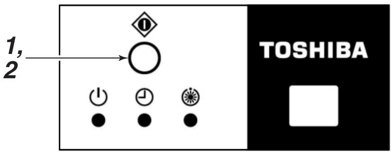
1 Start
Push temporary operation.
(If starting the operation when the room temperature is 24^ or higher, the mode enters COOL mode. If starting the operation when the room temperature is 24^ or lower, the mode enters HEAT mode.)
2 Stop
Push emergency operation once more.
CAUTION
- The ON switch of the test run and the ON switch of the test are used for the test run mode in the installation time. Do not use them in the normal time.
- If the "all stop" is selected in the normal/all stop switches, a signal from the remote controller is not accepted.
Emergency Operation (TCB-AX21E)
HOW TO PERFORM EMERGENCY OPERATION
In the following cases, operate the air conditioner in temporary by temporary operation of the operation part (inside of panel or indoor unit).
- The battery in the remote controller expired.
- A trouble occurred on the remote controller.
- The remote controller have disappeared.
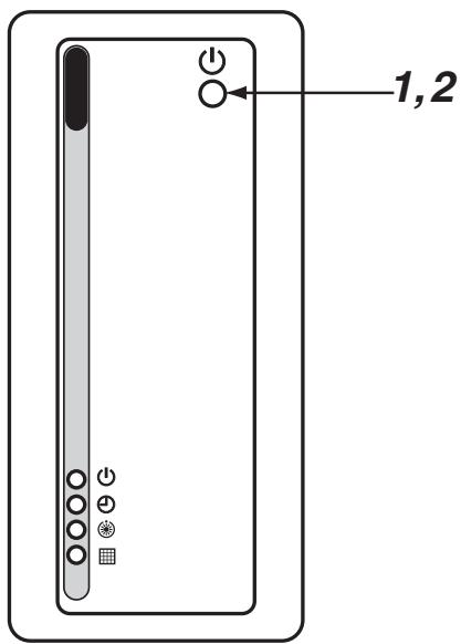
1 Start
Push temporary operation.
(If starting the operation when the room temperature is 24^ or higher, the mode enters COOL mode. If starting the operation when the room temperature is 24^ or lower, the mode enters HEAT mode.)
2 Stop
Push temporary operation once more.
CAUTION
- The ON switch of the test run and the ON switch of the test are used for the test run mode in the installation time. Do not use them in the normal time.
- If the "all stop" is selected in the normal/all stop switches, a signal from the remote controller is not accepted.
BEFORE ASKING REPAIR WORK
Before asking a repair work, check the following items.
| Phenomenon | Cause | Measures | |
| Check again | Operation does not start even if the switch is turned on. | Stopped? or after power failure? | Push Start/Stop of the remote controller. |
| Is the power supply of the power switch? | Turn on the power supply switch if not. | ||
| Fuse? | Contact the shop which you purchased the air conditioner. | ||
| Is not the mode ON timer? | Delete the timer operation. | ||
| Is not [ALL OFF] of [Signal Receiving Part] selected? | Set the switch to [Normal position], and stop the operation. | ||
| Is not the battery of the remote controller expired? | Replace the battery. | ||
| Is not the state of the display lamp “Disagreement of (cool) and (heat)” or “No A”? | Change the operation mode. | ||
| Phenomenon | Cause | |
| Contact the shop which you purchased the air conditioner | <Display lamp flashes.> | • It is a communication error between the sensor and the indoor unit, or setup error of the address when the wired remote controller is used. |
| 1 2 3 | • A communication error between the indoor unit and the outdoor unit. | |
| 1 2 3 4 | • A protective device of the indoor unit works. | |
| 1 2 3 4 | • A protective device of the outdoor unit works. | |
| 1 2 3 4 | • A trouble occurred on the temperature sensor. | |
| 1 2 3 4 | • The compressor of the outdoor unit is protected. | |
| 1 2 3 4 | • The test run is performed. Turn off the Trial ON switch. | |
Please check the above items. If the trouble yet remains, stop the operation, turn off the power switch, and then notify the shop which you purchased the air conditioner of the part No. and phenomenon. Never repair any part by yourself because it is very dangerous. If the display lamp is flashing, also tell of its contents.
4-1-4 Weekly timer (RBC-EXW21E)
Accessory parts
| Part Name | Q'ty |
| Program weekly timer | 1 |
| Connecting cable (Length: 1.2m) | 1 |
| Screws M4 x 25 | 2 |
| Wood screws | 2 |
| Spacer | 2 |
| Owner's Manual | 1 |
| Installation Manual | 1 |
Requirement to install the program weekly timer
Installing dimension for serial installation
When installing the program weekly timer (remote controller/system controller, etc.) to the wall surface, follow the installation procedure in (Fig. 1) and (Fig. 2).
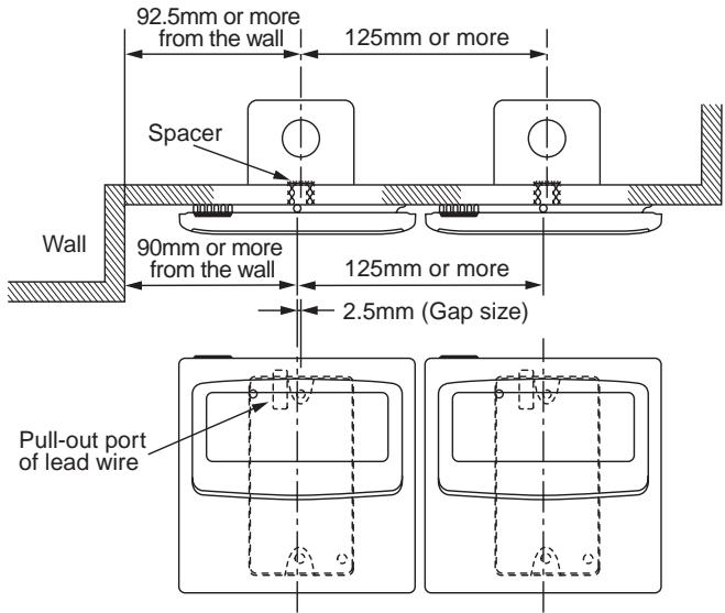
Fig. 1
*When installing the remote controller and the program weekly timer which are set in parallel at upper side and lower side, in consideration of maintenance, keep a clearance with 25mm or more.
How to install the program weekly timer
NOTE 1 :
Avoid to twist the program weekly timer cable with the power supply cable, etc. or to store them in the same metal pipe, otherwise it causes a malfunction.
NOTE 2 :
Install the program weekly timer apart from the generation source of noise.
NOTE 3 :
When noise is induced to the power source of the indoor unit, measures such as mounting the noise filter is necessary.
Install the program weekly timer to the box (Procured locally) which has previously inserted in the wall.
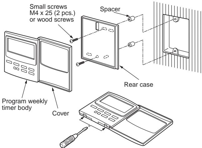
Fig. 2
- Inserting a minus screwdriver, etc. into the groove at the lower side of the program weekly timer, which appears when opening lid of the program weekly timer body, force open the rear case to remove it.
- Using the attached M4 screws or wood screws (2 pcs.), fix the rear case of the program weekly timer. Before installation, press to open the screw hole with a screwdriver, etc.
Fix it with the spacer, but not so strongly. If the program weekly timer does not fit closely to the wall, adjust it by cutting off the spacer.
- Connect the attached connecting cable (4 cores) to the program weekly timer body.
- Install the program weekly timer body by matching to hooks on the rear case and putting into the hooks.
Cabling
Connection diagram
(Be sure to use the attached connecting cable.)
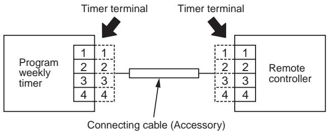
Arrangement
The program weekly timer and the remote controller can be arranged to either right or left side.
Cabling procedure
Perform cabling in the following procedure.
- Connect the attached connecting cable to the timer terminal (4P connector) of the program weekly timer. (Fig. 3)
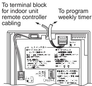
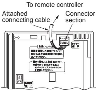
Fig. 3
- Pull the attached cable out of lead wire pullout port on the rear case of the program weekly timer and connect the cable to the timer terminal (4P connector) of the remote controller via inside of the wall. (Fig. 4)
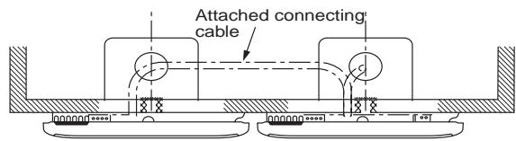
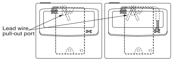
Fig. 4
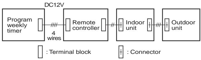
System diagram
Program weekly timer test run setup
After installation, check (OFF to ON) output status using the forced ON switch on the rear side of the program weekly timer P.C. board. Then check the normal operation and certainly turn OFF the forced ON switch.
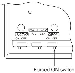
Memory backup function for power failure compensation
This program weekly timer stores in memory the contents set by the operation button during a power failure. Pushing (PROGRAM) button resumes the operation with the contents before the power failure when the power failure has been reset.
How to use [BACKUP]
After the installation work, check [BACKUP] switch on the rear side of the program weekly timer P.C. board is turned to ON side.
![TOSHIBA TCB-SC642TLE2 - How to use [BACKUP] - 1](/content/2025/01/121691/images/6e5927905663aa434dea977301303a5352e97db1e889ccfa29ea7db4ad11292d.jpg)
Explanation to customers
After the installation work, hand "Owner's Manual" and "Installation Manual" to the customers.
Explain use and maintenance methods to the customers according to "Owner's Manual".
Weekly timer (RBC-EXW21E)
NAME AND OPERATION OF EACH PART
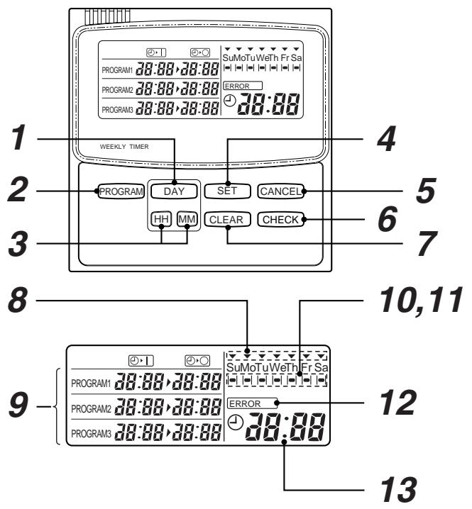
1 Day select button
The day of the week is selected.
Each pushing, mark moves in order of Sunday Monday Tuesday Wednesday Thursday Friday Saturday.
2 Program button
This button is used to set up the contents of the program operation.
3 Hour/Minute button
This button is used to set the present time and ON/OFF time.
4 Timer set button
This button is used to set the day of the week, hour, minute, holiday, and ON/OFF time.
5 Cancel button
This button is used to cancel as the holiday.
6 Check button
This button is used to confirm the contents of the setting items.
7 Cancel button
This button is used to cancel the setting items.
8 Display of the present day of the week (mark)
9 ON/OFF time display
ON/OFF time of the timer operation is displays.
10 Operation reserve indication (mark)
The day of the week when the program operation has been set is displayed.
11 Holiday setting indication ( | | mark)
The holiday is displayed (Cancel as holiday)
12 Setting error display
13 Present time display
Displays the present time displayed with 24-hours notation.
HOW TO USE THE TIMER CORRECTLY
1. Operation procedure
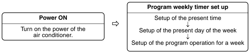
2. Turn on the power supply of the air conditioner
- Turn on the power supply of the air conditioner connected with a program weekly timer. (For cooling and heating, do not turn off the power supply for compressor heating.)
3. Setup of the present time
- Set the present time
(Example: Case that the present time is 11:45.)
1 While push SET button push HH button to select "hour" of the present time.
- While push SET button each pushing HH button, change sequentially.
$$ 0 \rightarrow 1 \rightarrow \dots \rightarrow 1 0 \rightarrow \dots \rightarrow 2 3 \rightarrow 0 $$
- While keep SET button pushed, continuous pushing HH button makes fast forward.
(Example: Leave the finger at display of 11, you can set 11 o'clock.)
- When release SET button, the hour is set, and mark changes flashing to light.
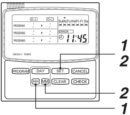
2 While push SET button push MM button to select "minutes" of the present time.
- While push SET button, each pushing MM button change sequentially.
$$ 0 0 \rightarrow 0 1 \rightarrow \dots \rightarrow 5 8 \rightarrow 5 9 \rightarrow 6 0 $$
- While keep SET button pushed continuous, pushing MM button makes fast forward.
(Example: Leave the finger at display of 45 you can set 45 minutes.)
- When release SET button, the minutes are set, and make changes flashing to light.
CAUTION
- The time cannot be changed only when button or button pushed.
- If 30 seconds have passed while the button is flashing without pushing DAY or HH / MM buttons, the display returns automatically to the original display (Normal display).
In this case, repeat the procedure from the 1st step.
4. Setup of the day of the week
- Set the today of the week. (Example: Case of Wednesday)
1 While push SET button push DAY button to select "today" of the week.
- While pushing SET button, each push DAY button, the display of the present day of the week flashes, and the display moves in order.
SuMoTu WeTh Fr Sa
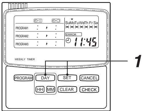
CAUTION
- The day of the week cannot be changed only when DAY button is pushed.
- If 30 seconds have passed while the button is flashing without pushing DAY or HH / MM buttons, the display returns automatically to the original display (Normal display). In this case, repeat the procedure from the 1st step.
5. How to set program timer operation
Set the present time and the present day of the week surely, otherwise the program operation is not correctly performed.
This timer can control up to 3 cycle program per day.
(1 cycle or 2 cycles can be also set up.)
The following items can be set to the program operation.
- Setup of [ON] [OFF] time ([ON] or [OFF] only cannot be set up singly.
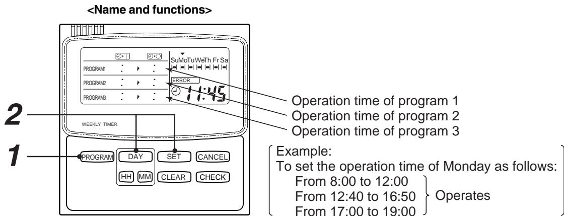
1 First push PROGRAM button.
- When pushing PROGRAM button, the reserve mark - flashes.
2 Push DAY button, select the day for operation and then push SET button.
When pushing SET button, the flashed reserve mark changes, and ON time of the program 1 flashes at the same time.

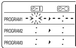
3 Set ON time by HH, MM) buttons, and then push SET button.
When push SET button, the flashed ON time (8:00 in example) change, and OFF time of the program 1 flashes at the same time.
| PROGRAM1 | 8.00 | → | 3.5 | ← |
| PROGRAM2 | : | ↑ | : | |
| PROGRAM3 | : | ↑ | : |
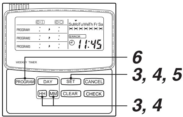
4 Set OFF time by HH/MM buttons, and then push SET button.
When pushing SET button, the flashed ON time (12:00 in example) changes, and ON time of the program 2 flashes.
5 Next set up the operation time to the program 2 and 3.
When pushing SET button after OFF time of the program 3 has been set, the flashed OFF time (19:00 in example) changes and ON time of the program 1 flashes.
6 Finally, push PROGRAM button.
Push (PROGRAM) button within 30 seconds after No. 5 step.
Then, one day timer (Monday in example) is set completely.
ON/OFF is displayed when the present time is included in the range of the set time.
(In the above status, the contents of the program 1 are displayed as the present time is included in the range from ON time to OFF time of the program 1.)
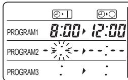
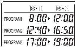
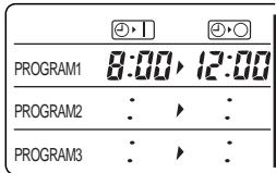
7 Setting to other day, repeat above procedure from 1 to 6.
If you need to set the same time as previous setting. Refer to "7. How to copy the program operation time".
CAUTION
- Setup of the program time: 0:00 is treated as 24:00. (Example) In the following cases, setup are available.
ON time
OFF time
0:00
2:00
22:00
0:00
- If 30 seconds have passed while the button is flashing without pushing DAY or HH / MM buttons, the display returns automatically to the original display (Normal display). In this case, repeat the procedure from the 1st step.
6. Set error
If flashing is displayed when the program operation has been set up, correct the time following the procedure below.
- When flashing ERROR is displayed, ON time of the failed program flashes.
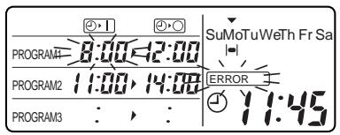
- Push SET button to flash the time to be corrected.
3.Using / buttons, correct ON/OFF time. - Push SET button. When the setup is correctly performed, ERROR display disappears.
- The correction has completed by pushing PROGRAM button.
CAUTION
- When ON/OFF time is set as follows, is displayed.
1) When a part of the operation time makes inroads into a part of another operation time
Example: ON time OFF time
$$ 8: 0 0 \quad 1 2: 0 0 $$
$$ 1 1: 0 0 \quad 1 4: 0 0 $$
2) When OFF time is ahead of ON time
Example: ON time OFF time
$$ 1 2: 0 0 \quad 8: 0 0 $$
3) When ON time is same as OFF time
Example: ON time OFF time
$$ 8: 0 0 \quad 8: 0 0 $$
4) ON time or OFF time is singly set up
Example: ON time OFF time
$$ B: \mathbb {O} [ \text {I s n o t s e t} ] $$
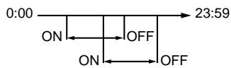
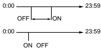
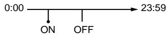
- The following cases are not set error.
1) OFF time of the previous cycle is same as ON time of the next cycle.
Example: ON time OFF time
$$ 8: 0 0 \quad 1 2: 0 0 $$
$$ 1 2: 0 0 \quad 1 9: 0 0 $$
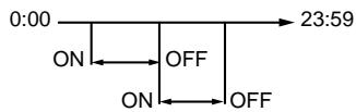
2) When the next cycle is set to the time before the set time of the previous cycle
Example: ON time OFF time ON time OFF time
$$ 1 2: 4 0 1 6: 5 0 \quad 1 2: 4 0 \quad 1 6: 5 0 $$
$$ 8: 0 0 1 2: 0 0 \quad 1 2: 4 0 \quad 1 6: 5 0 $$
Pushing the PROGRAM button changes the order in order of time.
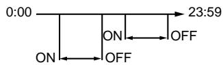
3) When both ON and OFF times are same 0:00
Example: ON time OFF time
$$ \begin{array}{c c} \mathbf {0}: \mathbf {0 0} & \mathbf {0}: \mathbf {0 0} \end{array} $$
Continuous operation for 24 hours
7. How to copy the program operation time
When setting the program operation, already set program can be copied and set to the other day of the week.
1 Push CHECK button in normal display.
2 Push DAY button and put the operation reserve indication on the day of the week of which the program operation is already set. (Monday in the example)
3 Push PROGRAM button.
Present day of the week indication and Operation reserve indication flash.
4 Push DAY button and put the present day of the week indication on the day of the week to be copied. (Tuesday in the example) (For continuous copying, push SET button, and then push DAY button.)
5 Push (PROGRAM) button. The operation reserve indication goes on under the copied day of the week.
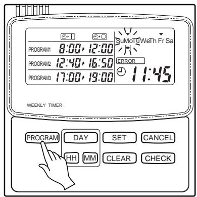
8. How to check the program operation time
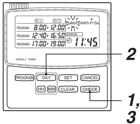
CAUTION
- While reserve indication is flashing, the display does not change even if other buttons are pushed than DAY, CHECK, and PROGRAM button.
- If 30 seconds have passed while the reserve indication is flashing without pushing DAY, CHECK or PROGRAM button, the display returns automatically to the original display. (Normal display)
1 Push CHECK button.
- The operation reserve indication - flashes in the normal display status.
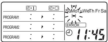
2 Push DAY button and put the operation reserve indication on the day of the week to be checked.
- Every pushing DAY button, the operation reserve indication - flashes and the contents of program operation time of the day of the week on which the operation reserve indication - has been put on is displayed.
| 20×1 | 20×2 |
| PROGRAM1 8:00, 12:00 | SuMaTuWerHFr Sa |
| PROGRAM2 12:40, 16:50 | ERROR |
| PROGRAM3 17:00, 19:00 | 11:45 |
3 Push CHECK button.
- It turns to be normal indication.
9. How to change the program operation time
1 Push (PROGRAM) button in the normal display status.
2 Select the required day reserve mark by pushing DAY button.
3 Push SET button.
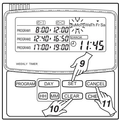
10. How to clear the program operation
- Clear of the day of the week
1) Push PROGRAM button.
2) Push DAY button and select the reserve mark to be cancelled.
3) Push CLEAR button. The program time disappears.
4) Push PROGRAM button. The operation reserve indication disappears.
- Clear of a part of the program
1) Push PROGRAM button.
2) Push DAY button and select the reserve mark on a to be cancelled.
3) Push SET button.
4) Push SET button again to flash ON or OFF time of the program to be cancelled.
5) Push CLEAR button. Then, a part of the program has been cancelled. At the same time, the remained programs are automatically arranged.
6) Push PROGRAM button.
4 Each push SET button, the flashing part changes in the following figure. Put the indication on the time to be changed.
5 Using /MM buttons, change the time.
6 Push SET button.
7 Push PROGRAM button. Then the change operation has completed.
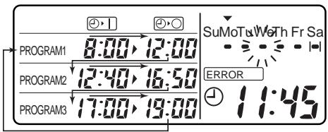
11. How to set up the holiday
- The operation reserve day can be cancelled by setting up the holiday.
1) Push CANCEL button. The holiday setup mark | | flashes.
2) Push DAY button and select the holiday setup mark | on the day which the holiday is set.
3) Push SET button. The flashing holiday setup indication | changes on. (I-)
- Clearance of [HOLIDAY] setup
1)Push CANCEL button.
2) Push DAY button and select the holiday setup mark | on the day to which the holiday is cancelled.
3) Push SET button. The holiday setup mark disappears and the operation reserve mark appears.
- Explanation of operation
The cancel setting day is temporarily canceled, and from the next day, the cancel setup mark || disappears and the operation reserve mark appears.
CAUTION
- For the day which does not set timer, the cancellation cannot be set.
12. Matters to be memorized
1. Power failure
When a power failure occurred and the power supply has been reset, the display of the right figure appears.
(A colon " : " flashes.)
- Resuming of operation
1) Turn on the power (breaker) of the air conditioner.
2) Start operation by the remote controller.
3) Push PROGRAM button of the program weekly timer. The flashing colon “:” changes to the clock display in the normal status. In this case, the program is memorized by the backup function. Therefore, it is unnecessary to set the program again.
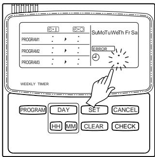
2. Operation of program weekly timer and air conditioner
An air conditioner mounted with a program weekly timer is operated on a remote controller and on the program weekly timer.
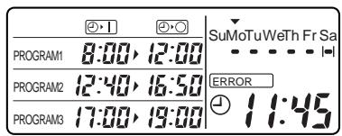
(Example)
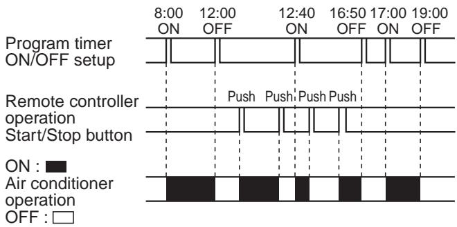
1) Operation pattern in a day
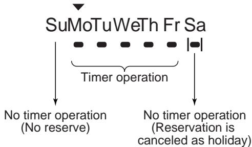
2) Operation pattern in a week
4-2 Central remote controller (TCB-SC642TLE)
4-2-1 Outline
1. Feature
Connectable units
- Max.64 of indoor units or groups can be connected and controlled in one central remote controller
- All indoor units can be divided to 1,2,3, or 4 zones.
- ALL / ZONE / GROUP (individual) control mode is selectable.
Up to 16 indoor units or groups for each zone.
Mode setting
(1) Central control / Remote control mode
Central control mode
Central controller is used as central control equipment.
Individual setting by remote controller can be inhibited by central remote controller.
Remote control mode
Central controller is used as remote controller.
Setting by central controller is inhibited by other central control equipments.
(2) ALL / ZONE mode
- ALL mode
All indoor units can be controlled by central controller.
ZONE mode
Indoor units in one of ZONE 1,2,3,or 4 can be controlled by central remote controller.
(3) Function of central controller is 10 types according to combination of central control / remote control mode and ALL / ZONE mode setting as the table below.
| Central control | Central control | |
| ALL | ALL / Central | ALL / Remote |
| ZONE 1 | ZONE1 / Central | ZONE1 / Remote |
| ZONE 2 | ZONE2 / Central | ZONE2 / Remote |
| ZONE 3 | ZONE3 / Central | ZONE3 / Remote |
| ZONE 4 | ZONE4 / Central | ZONE4 / Remote |
Operation function
Start / stop, Operation Mode select, Setting temperature, Air volume setting, Frap position select, Central 1,2,3,4 / individual select, Ventilation, etc.
Maximum number of connected central controller
Up to 10 units in one control wiring circuit.(including other central control devices.)
Display
LCD
Timer
Weekly timer (RBC-EXW21E) .... Sold separately
2. System configuration
- "ALL": All indoor units can be controlled by central remote controller.
- “ZONE” : Indoor units in one of ZONE 1, 2, 3 or 4 can be controlled by central remote controller.
- "GROUP": Indoor units of each group can be controlled individually.
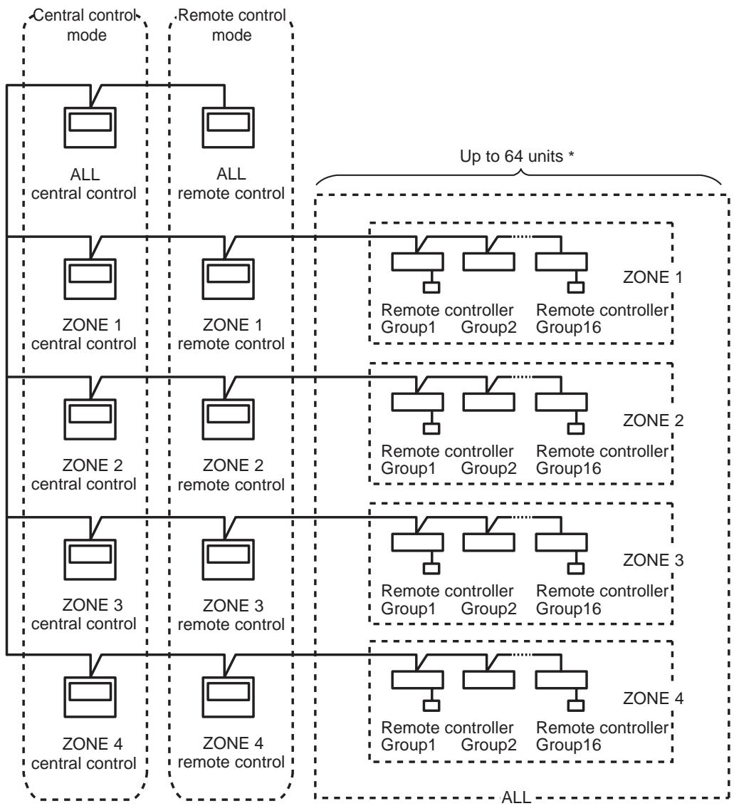
- In case of "1:1 model", follower indoor units in a group control and twin control must not be counted as "one unit". In case of VRF system, follower indoor units in a group control must be counted as "one unit".
3. Function matrix of central remote controller
| Central control mode | Remote control mode | |||||||||
| ALL Central control | ZONE 1 Central control | ZONE 2 Central control | ZONE 3 Central control | ZONE 4 Central control | ALL Remote control | ZONE 1 Remote control | ZONE 2 Remote control | ZONE 3 Remote control | ZONE 4 Remote control | |
| Controllable units | 64 group (zone 1 to 4) | 16 group (zone 1) | 16 group (zone 2) | 16 group (zone 3) | 16 group (zone 4) | 64 group (zone 1 to 4) | 16 group (zone 1) | 16 group (zone 2) | 16 group (zone 3) | 16 group (zone 4) |
| Operation units | ALL ZONE GROUP | ZONE GROUP | ZONE GROUP | ZONE GROUP | ZONE GROUP | ALL ZONE GROUP | ZONE GROUP | ZONE GROUP | ZONE GROUP | ZONE GROUP |
| ON | OK | OK | OK | OK | OK | OK *1 | OK *1 | OK *1 | OK *1 | OK *1 |
| OFF | OK | OK | OK | OK | OK | OK *1 | OK *1 | OK *1 | OK *1 | OK *1 |
| Operation mode change | OK | OK | OK | OK | OK | OK *1 | OK *1 | OK *1 | OK *1 | OK *1 |
| Setting temperature | OK | OK | OK | OK | OK | OK *1 | OK *1 | OK *1 | OK *1 | OK *1 |
| Setting air volume | OK | OK | OK | OK | OK | OK | OK | OK | OK | OK |
| Setting frap position | OK | OK | OK | OK | OK | OK | OK | OK | OK | OK |
| Central / Remote | OK *2 | OK *2 | OK *2 | OK *2 | OK *2 | X | X | X | X | X |
| Ventilation ON/OFF | OK | OK | OK | OK | OK | OK | OK | OK | OK | OK |
| Weekly timer connection | OK *3 | OK *4 | OK *4 | OK *4 | OK *4 | OK *5 | OK *6 | OK *6 | OK *6 | OK *6 |
| Batch operation display (LCD) | OK *7 | OK *8 | OK *8 | OK *8 | OK *8 | OK *7 | OK *8 | OK *8 | OK *8 | OK *8 |
| Batch alarm display (LCD) | OK *7 | OK *8 | OK *8 | OK *8 | OK *8 | OK *7 | OK *8 | OK *8 | OK *8 | OK *8 |
x...Disable
1 Individual ON/OFF operation with the remote controller is inhibited under the "central 1" mode.
Individual ON/OFF operation, MODE, and Temp. setting operations with the remote controller are inhibited under the "central 2" mode. Individual MODE and Temp. setting operations with the remote controller are inhibited under the "central 3" mode. Individual MODE operation with the remote controller is inhibited under the "central 4" mode.
2 "central 1" "central 2" "central 3" "central 4" "individual" can be set.
3 ON, OFF, remote control permitted / inhibited per ALL can be selected. (6 type)
4 ON, OFF, remote control permitted / inhibited per ZONE can be selected. (6 type)
5 ON, OFF per ALL can be selected. (2 type)
6 ON, OFF per ZONE can be selected. (2 type)
7 Per ALL
8 Per ZONE
- Function items of central remote controller (TCB-SC642TLE)
| No | Items | Function | Remarks | |
| 1 | Power Supply | AC220/230/240V | ||
| 2 | Connectable indoor units | Max. 64 units | ||
| 3 | Max. zone control units | Max. 4 zones | ||
| 4 | Controllable indoor units per zone | Max.16 units | ||
| 5 | Zone setting | Zone.1: Central control address 1 to 16Zone.2: Central control address 17 to 32Zone.3: Central control address 33 to 48Zone.4: Central control address 49 to 64 | ||
| 6 | Monitoring | ON/OFF | Available | |
| Operation mode | Available | |||
| Set up temperature | Available | |||
| Air volume select | Available | |||
| Frap position | Available * | * Remote controller less system only | ||
| Error contents | Available | |||
| Filter sign | Available | |||
| 7 | Setting | ON/OFF | Available | |
| Operation select | Available | |||
| Setting temperature | Available | |||
| Setting air volume | Available | |||
| Setting frap position | Available * | * Remote controller less system only | ||
| Reset filter sign | Available | |||
| Individual operation | Available | |||
| Master zone control | Available | |||
| Individual control in the zone | Available | |||
| Master operation | Available | |||
| Control with ventilation fan | Available | |||
| 8 | Restriction of local remote controller | Available1) Operation disable2) ON/OFF, mode select and setting temp. disable3) Mode select and setting temp. disable4) Mode select disable | ||
| 9 | Weekly schedule | Available(by connecting weekly timer) | ||
| 10 | Forced stop command(Fire alarm) | Available | ||
| 11 | Master ON/OFF command | Available | ||
| 12 | Stop command | Available | ||
| 13 | External operation output | Available | ||
| 14 | Error output | Available | ||
| 15 | Connectable central control devices | Up to 2 devices (Master / Sub) | In case of "zone fix mode", Up to 5 units(Master, zone 1,2,3,4) | |
| 16 | Display | Operation status display for each zone | ||
5. Zone control
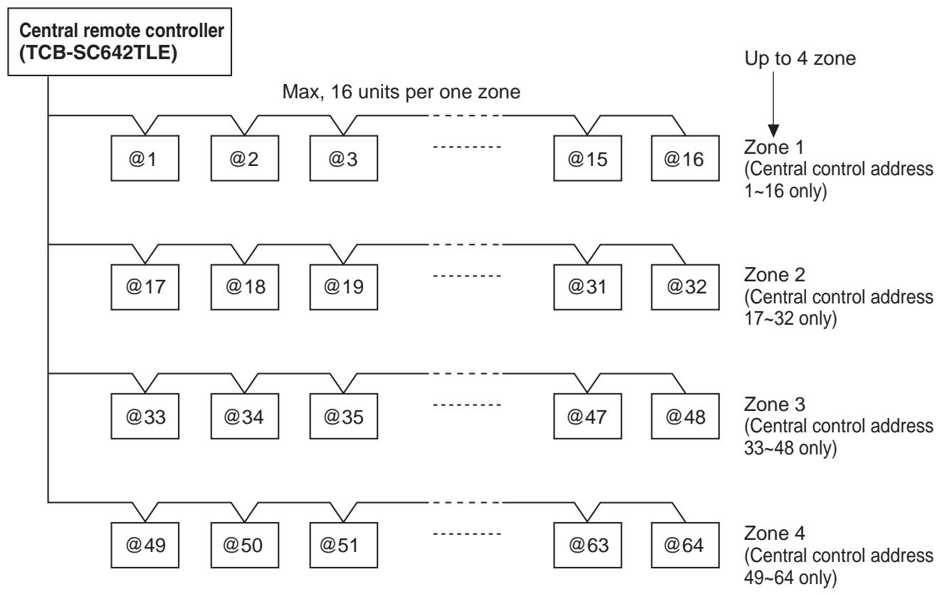
4-2-2 Installation procedure
1. General
This booklet briefly outlines where and how to install the central controller. Please read over the entire set of instructions for the indoor and outdoor units and make sure all accessory parts listed are with the controller before beginning.
NOTE
Give these instructions to the customer after finishing the installation.
| Part Name | Figure | Q'ty | Remarks |
| Central controller | 1 | ||
| Tapping screw | Truss-head Phillips 4 x 16 mm | 4 | For securing the central controller |
| Rawl plug | 4 | For securing the central controller | |
| Manual | 1 | For installation | |
| 1 | For operation |
2. Installation site selection
Install the central controller at a height of between 1 and 1.5 meters above the floor.
Do not install the central controller in a place where it will be exposed to direct sunlight or near a window or other place where it will be exposed to the outside air.
Be sure to install the central controller vertically, such as on a wall.
3. How to install the central controller

CAUTION

WARNING
Do not twist the control wiring together with the power wiring or run it through the same metal conduit, because this may cause a malfunction.
Install the central controller away from sources of electrical noise. Install a noise filter or take other appropriate action if electrical noise affects the power supply circuit of the unit.
Do not supply power to the unit or try to operate it until the tubing and wiring to the outdoor unit is completed.
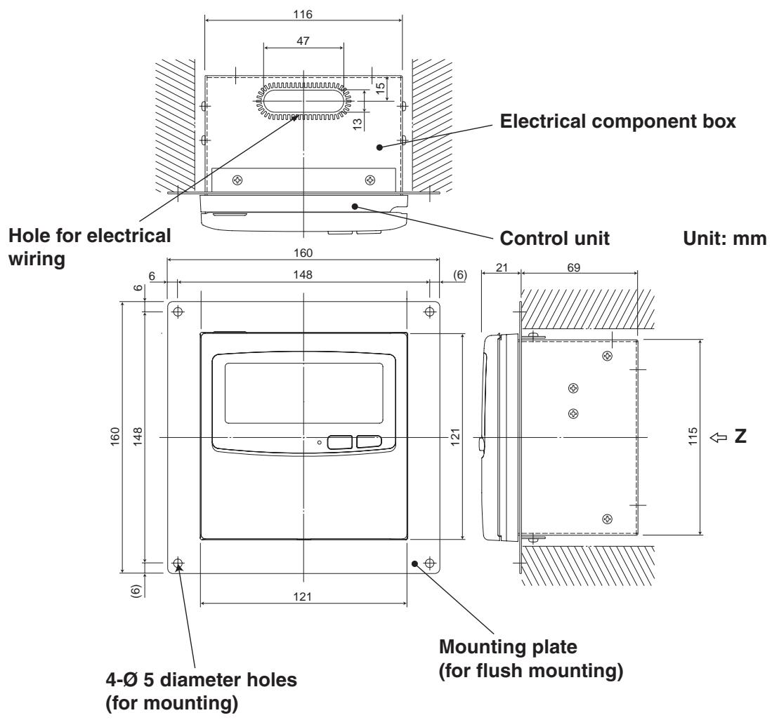
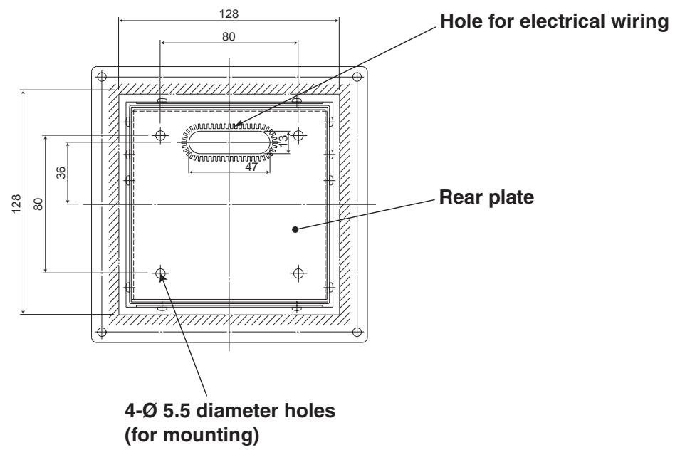
Fig. 1
Z-view (back side)
- In order to mount the central controller flush with the wall, an opening measuring 128mm× 128mm is necessary.
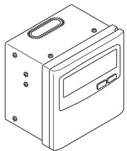
a): Normal mounting
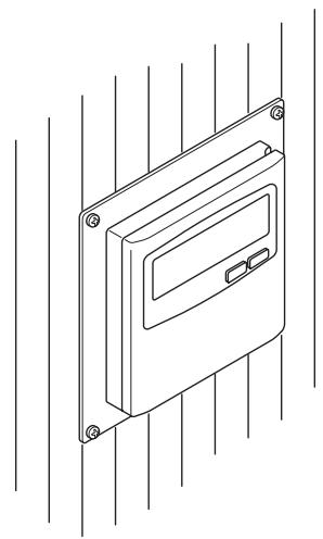
b): Flush mounting
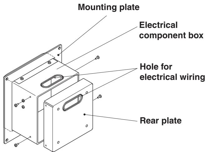
Fig. 2
- Decide how the central controller will be mounted: in the normal manner or flush with the wall.
a) To mount the central controller in the normal manner, remove the mounting plate. Then reattach the four screws to the electrical component box.
b) To mount the central controller flush with the wall, make an opening in the wall measuring 128mm× 128mm . The opening must be at least 85mm deep as measured from the outside surface of the wall.
- Remove the rear plate and connect the electrical wiring.
1) Remove the four screws located on both sides of the rear plate.
2) Either the hole in the top of the electrical component box or the hole in the rear plate may be used to feed the electrical wiring.
3) If the hole on top is used, the rear plate should be turned upside down.
- Secure the central controller in place.
a) If the central controller is being mounted in the normal manner, first attach the rear plate to the wall using the screws and Rawl plugs provided. Next, place the body of the central controller over the rear plate and secure it in place using four screws.
b) If the central controller is being mounted flush with the wall, fit it through the mounting plate on the wall and secure it in place using the screws and Rawl plugs provided.
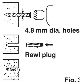

To mount the central controller on a wall made of cinder block, brick, concrete, or a similar material, drill 4.8 ~mm diameter holes in the wall and insert Rawl plugs to anchor the mounting screws.
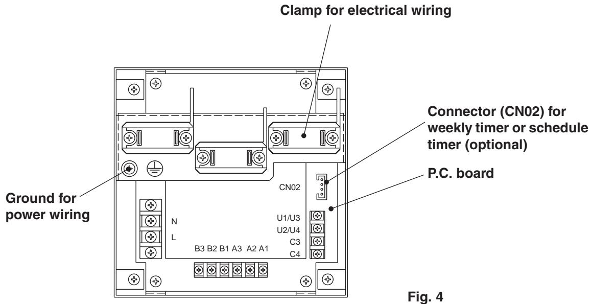
How to connect electrical wiring
1) Basic wiring
L: Power supply ( 50 Hz/60 Hz, 220-240 V)
N:
U1/U3: Indoor unit control wiring. (Low voltage) U2/U4:
C3: Auxiliary
C4: Ground for inter-unit control wiring
Ground for power wiring
2) Terminals for remote monitoring
A1: Input for turning on air conditioners concurrently.
A2: Input for turning off air conditioners concurrently.
A3: Common input for turning air conditioners on or off.
B1: On operation state indicator output.
B2: Alarm indicator output.
B3: Common indicator output.

CAUTION
Ensure that wiring connections are correct. (Incorrect wiring will damage the equipment.)
How to wire the central controller
In order to ensure safety, turn off the air conditioner power before mounting or removing the central controller.
Connect the communication wires to the indoor/outdoor unit connecting wires or central control system wires.
Use the following as the communication wires.
Total wire length of less than 1,000 meters: MVVS1.25mm²
Total wire length of less than 2,000 meters: MVVS2.0mm²
The total wire length is obtained by adding the lengths of the indoor/outdoor unit connecting wires to the lengths of the central control system wires.
Do not run the communication wires inside the same electrical wire conduits as the power cables, connect them using similar wires or allow them to be routed near other wires.
For the communication wires, use signal wires that visually identify them as being different from either the remote controller wires or the power cables.
Connect the power cable of the central controller to the AC220-240V power source. (Incorrect wiring will damage the equipment.)
Connect the wires in such a way that none of the wires will be connected incorrectly. (Incorrect wiring will damage the equipment.)
Connect the communication wires of the air conditioners shown which is the wiring employed when using central control is used.
The maximum number of air conditioners which can be connected in one central control system is 64 indoor units and 16 outdoor units (header outdoor units). (With VRF system)
Up to ten central controllers including other central control units can be connected.
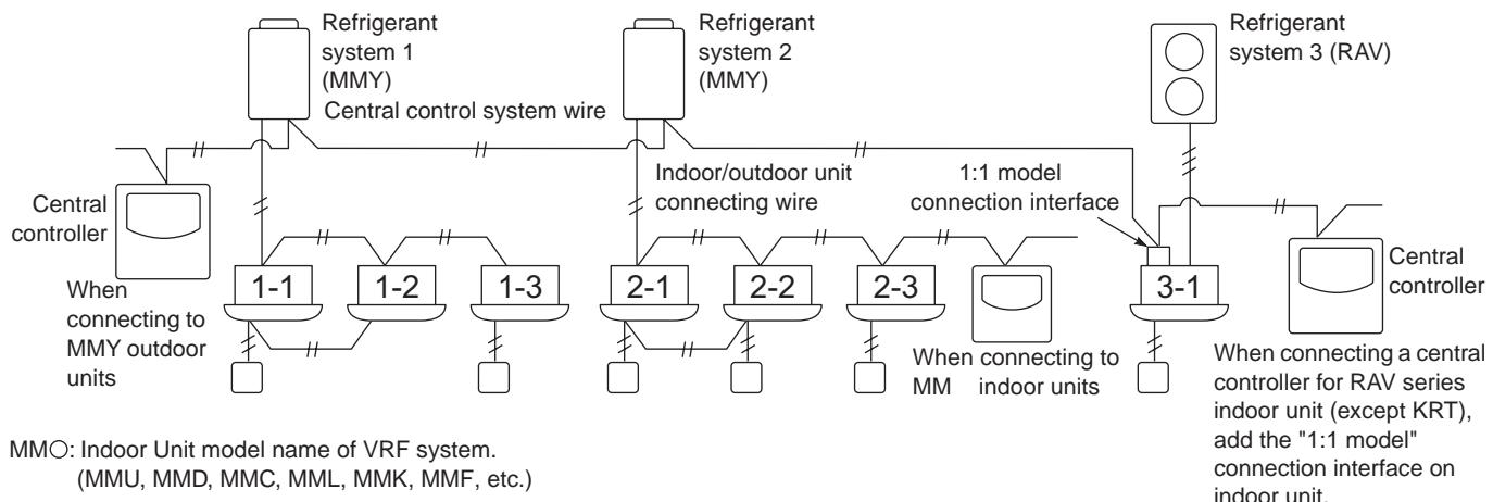
Fig. 5
NOTE
When connecting to MMY outdoor units, make the connection to the central control system wires (U3 and U4 terminals).
When connecting to MM indoor units, make the connection to the indoor/outdoor unit connecting wire (U1 and U2 terminals).
When connecting to a RAV air conditioner, make the connection to the U3 and U4 terminals.
The 1:1 model connection interface is required for the RAV air conditioner. (except KRT series.)
As shown in the figure below, connect the terminal block (U1/U3, U2/U4) of the central controller with the terminals (U3, U4) of the outdoor unit (central unit).
It is also possible to connect to the indoor/outdoor unit connecting wire terminals (U1, U2) of the indoor or outdoor unit (no matter which refrigerant system is used).
Since the terminals do not have polarities, U1/U2 or U3/U4 can be reversed.
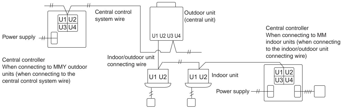
Fig. 6
NOTE
The fuse will blow to protect the equipment if an AC voltage of 220 - 240V is applied by mistake to U1/U3 or U2/U4. If this should happen, first re-connect the terminals properly, and then connect the communication wire to the U1/U3 and spare terminals. Check the fuse on the indoor/outdoor control board since this fuse may have blown as well.
Terminate the connection of the shielded wires for all the central control wires, and provide single-point grounding.
Even when connecting the centrally controlled unit to the indoor/outdoor unit connecting wires, terminate the connection of the shielded wires, and provide single-point grounding for all the indoor/outdoor unit connecting wires.
Leave the final termination open (insulate it).
Fig. 7
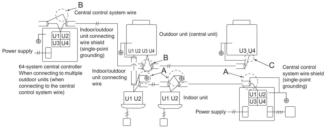
Area A: Ground both ends of the shielded cable used for the indoor/outdoor unit connection.
Area B: Connect a shielded cable for the central control system wiring.
Area C: Ground only one end of the central control system wiring at its final termination. (Leave the other end of the wire at its final termination as an open wire (i.e. insulate it).)
64-system central controller
When connecting to multiple indoor units (when connecting to the
indoor/outdoor unit connecting wire)
4. Address switch setting
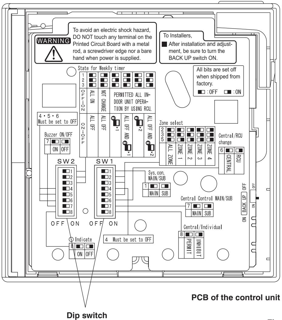
Fig. 8

Fig. 9
How to reach the P.C. board
Remove the flat-top screw on the bottom of the back case. When you open up the decorative cover, you will see two notches under the control unit. Inset a coin or other flat object into these notches and pry off the back case. The P.C. board on the back of the control unit is now visible.
SW1
Main/sub selection switch
OFF: Central controller operates as main controller.
ON: Central controller operates as sub-controller.
ALL/ZONE mode selection switch
ALL mode:
All indoor units can be controlled by central controller.
ZONE 1, 2, 3, 4 mode:
Indoor units in one of zone 1, 2, 3, or 4 can be controlled by central controller. All indoor units cannot be set.
| 2 | 3 | 4 | 5 | |
| ALL mode | OFF | OFF | OFF | OFF |
| ZONE 1 mode | OFF | OFF | ON | |
| ZONE 2 mode | ON | OFF | ON | |
| ZONE 3 mode | OFF | ON | ON | |
| ZONE 4 mode | ON | ON | ON |
Central control/Remote control mode selection switch
OFF: Central control mode.
Individual setting by remote controller can be inhibited by central controller.
ON: Remote control mode.
Setting by central controller is inhibited by other central control equipments.
Central control Main/Sub selection switch
(OFF: Main, ON: Sub)
① When AMY adaptor etc. is used with central controller, set the switch to ON position.
② When only one central controller is used, set the switch to OFF position.
③ Except ①, when multiple central controllers are used, set only one central controller to OFF position and others to ON position.
ALL mode central controller to be OFF position.
(recommended)
(Central control) button operation switch
OFF: (Central control) button operation is permitted.
ON: button operation is inhibited.
*All switches are OFF position at shipment.
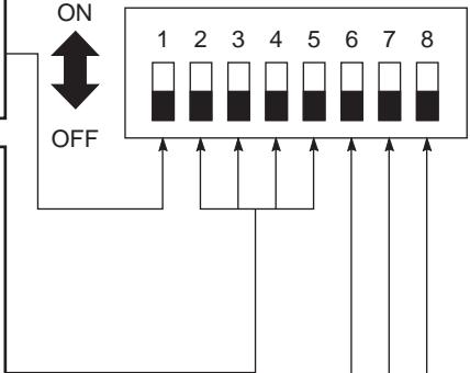
SW1
Fig. 10
SW2
Weekly timer input switches
Central controller operation can be set when weekly timer activates (ON/OFF).
| Switch No. Central controller operation | 1 | 2 | 3 | ||
| Timer OFF ON | Timer ON OFF | ||||
| ① | ALL ON | ALL OFF | OFF | OFF | OFF |
| ② | No change | ALL OFF | ON | OFF | OFF |
| ③ | Individual control of all indoor units to be permitted | All indoor units to be 1*1 | OFF | ON | OFF |
| ④ | Ditto | ALL OFF and all indoor units to be 1*1 | ON | ON | OFF |
| ⑤ | Ditto | All indoor units to be 2*2 | OFF | OFF | ON |
| ⑥ | Ditto | All OFF and all indoor units to be 2*2 | ON | OFF | ON |
In case of Remote control mode, use ① or ②.
In case of ZONE 1, 2, 3, 4 mode, ALL, all indoor units means one of ZONE 1, 2, 3, 4.
1: 1 (Central control 1) means ON/OFF operation cannot execute by remote controller.
^2 : 2 (Central control 2) means ON/OFF, MODE change. Temp. setting cannot be executed by remote controller.
Auxiliary switch
Must be set to OFF position.
Beep tone switch
OFF: Beep tone when each button is pushed.
ON: No tone when each button is pushed.
Indication switch
Normally set to OFF position.
When set to ON position, indication is not displayed on LCD of central controller.
*All switches are OFF position at shipment.
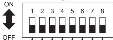
2
Fig. 11
5. Mode setting
According to function of each central controller, set SW1 as Fig. 12.
(1) Central control/Remote control mode
Central control mode
Central controller is used as central control equipment.
Individual setting by remote controller can be inhibited by central controller.
Remote control mode
Central controller is used as remote controller. Setting by central controller is inhibited by other central control equipments.
(2) ALL/ZONE mode
ALL mode
All indoor units can be controlled by central controller.
ZONE mode
Indoor units in one of ZONE 1, 2, 3 or 4 can be controlled by central controller.
(3) Function of central controller is 10 types according to combination of central control/remote control mode and ALL/ZONE mode setting as the table 1.
(4) Stick the central controller unit label in a conspicuous position.
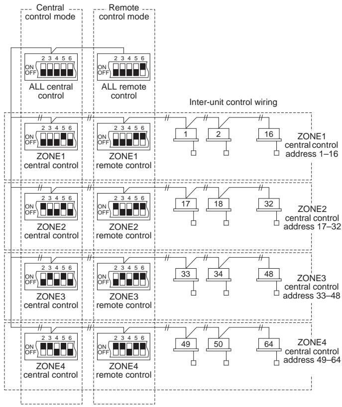
Fig. 12
Table 1
| Central control | Remote control | |
| ALL | 1. ALL/Central | 6. ALL/Remote |
| ZONE1 | 2. ZONE1/Central | 7. ZONE1/Remote |
| ZONE2 | 3. ZONE2/Central | 8. ZONE2/Remote |
| ZONE3 | 4. ZONE3/Central | 9. ZONE3/Remote |
| ZONE4 | 5. ZONE4/Central | 10. ZONE4/Remote |
6. How to perform zone registration
To operate the central controller properly, zone registration is required after finishing the test run (and after setting all indoor unit addresses) using one of the following methods.
Procedures common to all units
- Connect the U1/U2 terminals to the relay connectors of the U3/U4 terminals inside the outdoor unit (central unit).
- Leave the SW30-2 switch on the outdoor unit (central unit) interface board at the ON position for one system only, and set all the other switches to OFF. (For details on the SW-30 position, refer to the wiring diagram provided with the outdoor unit.)
(a) Zone registration using the remote controller (RBC-AMT21E) Refer to page 16
(b) Zone registration using the central controller (TCB-SC642TLE) Refer to page 17
(c) Automatic zone registration using the central controller (TCB-SC642TLE) Refer to page 18
For methods (a) and (b), you should make a zone registration table manually before performing the registration as shown on the page 15.
For method (c), zone registration is executed automatically, proceeding from small indoor unit address and small central addresses to larger numbers in numerical order. For example:
For methods (b) and (c)
These methods are not supported by the RAV models.
For RAV models, initiate the zone registration described in (a).
Wait at least 10 minutes after the power has been turned on before starting to set the addresses.
It may take up to 10 minutes (although it usually takes 3 minutes) to establish initial communication between the indoor and outdoor units. If the addresses are set before this communication is completed, the central address may fail to be set in some of the indoor units.
| Central adress | 1 | 2 | 3 | 4 | 5 | 6 | |
| ZONE-group | 1-1 | 1-2 | 1-3 | 1-4 | 1-5 | 1-6 | |
| Indoor unit address | 1-1 | 1-2 | 2-1 | 2-2 | 2-3 | 3-1 |
NOTE
- An indoor unit address is assigned to each indoor unit during automatic address operation. Each indoor unit address combines an R.C. address and indoor unit number as follows:
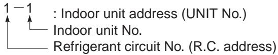
This address is displayed on remote controller for UNIT No. when the UNIT button is pressed.
- The central address represents the zone and group number. These addressed are assigned in ascending numerical order.
- For details on how to set the addresses when the TCC-LINK adapter is connected for central control, refer to these instructions and to the installation instructions of the TCC-LINK adapter.
| ZONE | GROUP | Central address | Indoor unit address (UNIT No.) | Unit location | ZONE | GROUP | Central address | Indoor unit address (UNIT No.) | Unit location |
| 1 | 1 | 1 | 3 | 1 | 33 | ||||
| 2 | 2 | 2 | 34 | ||||||
| 3 | 3 | 3 | 35 | ||||||
| 4 | 4 | 4 | 36 | ||||||
| 5 | 5 | 5 | 37 | ||||||
| 6 | 6 | 6 | 38 | ||||||
| 7 | 7 | 7 | 39 | ||||||
| 8 | 8 | 8 | 40 | ||||||
| 9 | 9 | 9 | 41 | ||||||
| 10 | 10 | 10 | 42 | ||||||
| 11 | 11 | 11 | 43 | ||||||
| 12 | 12 | 12 | 44 | ||||||
| 13 | 13 | 13 | 45 | ||||||
| 14 | 14 | 14 | 46 | ||||||
| 15 | 15 | 15 | 47 | ||||||
| 16 | 16 | 16 | 48 | ||||||
| 2 | 1 | 17 | 4 | 1 | 49 | ||||
| 2 | 18 | 2 | 50 | ||||||
| 3 | 19 | 3 | 51 | ||||||
| 4 | 20 | 4 | 52 | ||||||
| 5 | 21 | 5 | 53 | ||||||
| 6 | 22 | 6 | 54 | ||||||
| 7 | 23 | 7 | 55 | ||||||
| 8 | 24 | 8 | 56 | ||||||
| 9 | 25 | 9 | 57 | ||||||
| 10 | 26 | 10 | 58 | ||||||
| 11 | 27 | 11 | 59 | ||||||
| 12 | 28 | 12 | 60 | ||||||
| 13 | 29 | 13 | 61 | ||||||
| 14 | 30 | 14 | 62 | ||||||
| 15 | 31 | 15 | 63 | ||||||
| 16 | 32 | 16 | 64 |

-
Assign indoor unit addresses to the desired positions (central addresses) manually.
-
For group control, only the main indoor unit should be assigned. Sub indoor units cannot be assigned.
(a) Zone registration using the remote controller (RBC-AMT21E)
(Determination of central address)
This method is not supported by the RAV models. For RAV models, initiate the zone registration described in (a).
In this case, after confirming which indoor unit is connected to the remote controller and that the air conditioner in the OFF state, you set the central addresses one at a time.
If the system has no remote controller, connect a remote controller to the system temporarily. Then follow this procedure.
NOTE
The indoor unit address must already have been set before performing zone registration. If necessary, refer to the Installation Manual supplied with the outdoor unit.
(1) Press the l and 电 buttons at the same time of the remote controller for more than 4 seconds.
(2) Do not press UNIT button.
(3) Once in this mode, the UNIT No., CODE No., No. of SET DATA and SETTING indications will flash on the display as shown Fig. 13.
NOTE
In case of group control "ALL" instead of "UNIT No." will flash on the display. Select the main indoor unit address by pressing the UNIT button once.
(4) Set CODE No. to 03 using the and ( 出 ) buttons.
NOTE
The CODE No. 03 must be selected to perform zone registration using the remote controller.
(5) Set the Central address which you want to assign to the indoor unit address using the and ( 4 ) buttons according to the zone registration table.
(6) Press the SET button. The CODE No. and Central address changes from flashing to ON state. If you make mistake, then press the CL button and reset the central address.
(7) Press the button to finish zone registration.
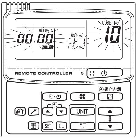
Fig. 13
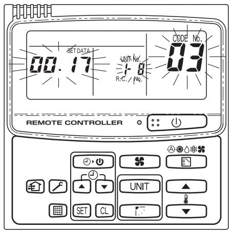
Fig. 14
For example, in this case
Indoor unit address: 1-8
Central address: 17 (ZONE 2, GROUP 1)
(b) Zone registration using the central controller (TCB-SC642TLE)
This method is not supported by the RAV models.
For RAV models, initiate the zone registration described in (a).
In this case, you set all Central addresses by central controller at once manually.
(1) Press the and buttons at the same time for more than 4 seconds.
SETTING and CODE No. C1 will flash.
(2) After confirming that CODE No. C1 is displayed, press the SET button. Once in this mode, a change takes place as Fig. 15.
(3) Select the zone and group No. which you want to set with ZONE and (GROUP) buttons. If already set, press the CL buttons.
(4) Set the unit No. (Indoor unit address) with and buttons, according to the zone registration table.
R.C. No. button
Indoor unit No. ① button
(5) Press the SET button.
GROUP No. turns ON and UNIT No. (Indoor unit address) changes from flashing to ON state. UNIT No. is registered to selected ZONE No. and GROUP No.
If you make mistake, then press the CL button and reselect the ZONE, GROUP and UNIT No.
(6) Register the other UNIT No. in the same way by following the steps (3) to (5).
(7) Finally, complete the registration by pressing the button.
SETTING flashes for a few minutes, then OFF.
If data is registered the unit No. is displayed.
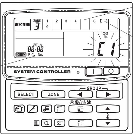
If no data is registered no number is displayed. Selected group No.if no data is registered.
Fig. 15
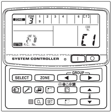
Fig. 16
For example, in the case at left
Zone 3, group No. 7
Unit No. (indoor unit address) 2-8
Unit No. 2-8 is registered to zone 3-group 7.
(c) Automatic zone registration using the central controller (TCB-SC642TLE)
(1) Press the and ZONE buttons at the same time for more than 4 seconds. SETTING and CODE No. C1 will flash.
(2) Select CODE. No. C2 by pressing and ( ) button and press the SET button. C2 changes from flashing to ON state and automatic zone registration will start.
(3) Registered GROUP No. will be disappeared all.
(4) Central address will be assigned from small indoor unit address to large one in numerical order automatically. Finishing automatic zone registration, SETTING changes from flashing to OFF.
(5) If the error is happened, the "CHECK" starts flashing and zone registration finishes at this time. Press the button.
(6) Finally, complete automatic zone registration mode by pressing the button. SETTING flashes for a few minutes, then OFF.
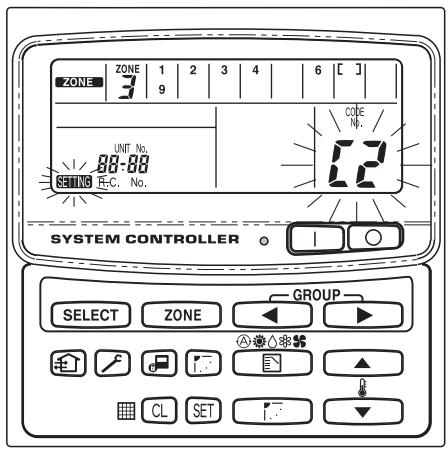
Fig. 17
7. Checking from the central controller for duplication of the central address
Central address duplication error check: C3
- This cannot be used with RAV air conditioners. For further details, refer to the instructions of the TCC-LINK adapter.
(1) Hold down the and buttons together for at least four seconds. (CODE No. C1 starts flashing.)
(2) Press the or ( ) button to select CODE No. C3.
(3) When the SET button is now pressed, CODE No. C3 lights and SETTING flashes. The central address duplicated error check now starts.
(4) The addresses of all the indoor units is checked in sequence starting with outdoor unit system 1. The check is completed when CODE No. C3 flashes and SETTING goes off.
(5) If any duplication is discovered among the central addresses, the GROUP No. will flash.
Press the or ( 业 ) button to select CODE No. C1, and press the button.
The central address is cleared by selecting the area where the GROUP No. is flashing and by pressing the button. Set the correct central address using the wired remote controller or the central controller.
(6) Press the button to complete the procedure.
Setting flashes for several minutes, the initial setting is automatically established, and the procedure is completed.
8. Connections with external equipment
| Designation | Input/output item | Central controller side | Equipment side | |||
| Input/output conditions | Terminal name | Demarcation terminals | Circuitry example | Input/output conditions | ||
| Digital input/output terminals | Status output | Operate outputAlarm output“A” (normally open) contact without voltageStatic (relay output)Allowable contact voltage, current:DC 30 V, 0.5 A | OperateAlarmOutput common | CPEV0.9 to 1.2 | Digital input | Wiring length:Max. 100 meters |
| Control input | All operate inputAll stop input“A” (normally open) contact with voltagePulse(photocoupler input)Allowable contact voltage, current:DC 24 V, 10 mA | All operate (+)All stop (+)All stop (+)Input common (-) | CPEV0.9 to1.2 | +24V | Pulse width:300 ms or moreWiring length:Less than 100 meters | |
9. Memory back up switch
Check the back up switch is ON for back side of central controller PCB.
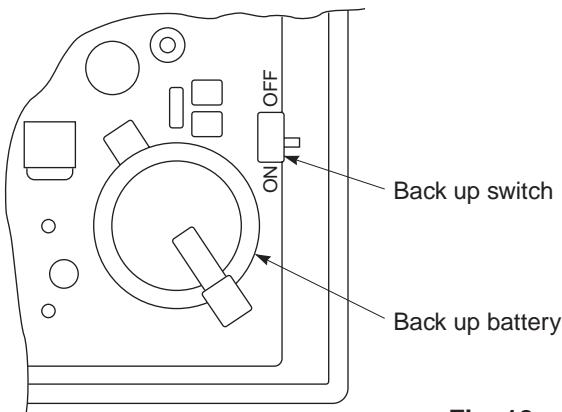
Fig. 18
10. Test run of the central controller
(1) Power on for all indoor units. Next, power on for central controller.
SETTING will flash, checking the indoor unit address automatically.
(2) If group No. displayed on central controller is not same as indoor unit No.* which is connected, see Fig. 7 and setting again.
*In case of group control, main unit No. only.
11. How to perform an air conditioner test run
(1) Hold down the button of the central controller for at least four seconds. During the test run, "TEST" appears on the LCD display.
(2) Press the and 1 buttons.
The temperature cannot be adjusted at the "TEST" position.
Do not use this procedure except when performing a test run since it will strain the equipment.
(3) Upon completion of the operation, press the button, and check that "TEST" on the LCD display has gone off.
4-2-3 Operation procedure
How to Use the Central Controller
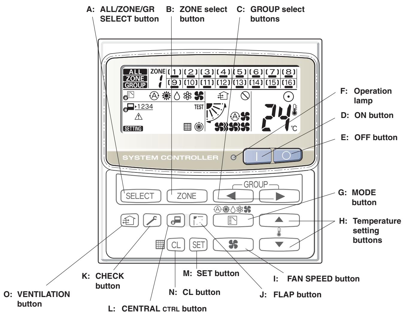
Functions of buttons
| A: ALL/ZONE/GR SELECT button ALL SELECT | Use this button to select one of the following: ALL: Used for turning all the air conditioners on and off. ZONE: Used for turning all the air conditioners of each zone on and off. GR: Used for turning all the air conditioners of each group on and off. A maximum of four zones and 16 groups (units) in a zone can be set. | |
| B: ZONE select button ZONE | Use this button to select a zone (1 to 4) to operate individually. | |
| C: GROUP select buttons < > | Use these buttons to select a group (1 to 16) to operate individually. | |
Functions of buttons (Continued)
| D: ON button | This button is for turning the selected air conditioner on. |
| E: OFF button | This button is for turning the selected air conditioner off. |
| F: Operation lamp | This lamp lights when the unit is turned on. |
| G: MODE button | Use this button to select one of the following five operations: ▲: Used to automatically set cooling or heating operation. Some models are not provided with a mode for automatically setting the cooling or heating operation. (temperature range: 18 to 29 °C) |
| ▲: Used for normal heating operation. Only for heat pump type (temperature range: 18 to 29 °C) | |
| △: Used for dehumidifying without changing the room temperature. (temperature range: 18 to 29 °C) | |
| ▲: Used for normal cooling operation. (temperature range: 18 to 29 °C) | |
| ■: Used to run the fan only, without heating or cooling operation. When the ▽ indication is displayed, you cannot change the mode from ▽ and ▽ or ▽ to ▽ and ▽. To change the mode, turn off all units once then select the mode again. | |
| H: Temperature setting buttons | ▲: Press this button to increase the temperature setting. ▼: Press this button to decrease the temperature setting. |
| I: FAN SPEED button | ▲: The air conditioner automatically decides the fan speed. ▲: High fan speed. ▲: Medium fan speed. ▲: Low fan speed. |
| 1. Use this button to set the airflow direction to a specific angle. The airflow direction is displayed on the remote control unit. Operation mode Number of airflow direction settings ★ (COOL) or △ (DRY) 3 ★ (HEAT) or ★ (FAN) 5 ★ (AUTO) Cooling mode: 3 Heating mode: 5 In the cool mode and dry mode, when the flaps are set in a downward position, condensation may form and drip around the vent. Do not move the flap with your hands. | |
| This function is available only for 4-Way air discharge cassette type and Under ceiling type. | |
| 2. Use this button to make the airflow direction sweep up and down automatically. Press this button several times until the (▼) symbol appears on the display. | |
| 1) The flap setting can be performed only for units that have no remote controllers. 2) In the ALL or ZONE mode, no flap setting can be performed. If necessary, you should select the GR mode and use the FLAP button. | |
| Note | |
| K: CHECK button CAUTION | This button is used only when servicing the air conditioner. Do not use the CHECK button for normal operation. |
| L: CENTRAL CTRL button | Use this button to inhibit individual operation by remote controller as follows: 1: Individual ON/OFF operation is inhibited. 2: Individual ON/OFF, MODE and Temperature setting operation is inhibited. 3: Individual MODE and Temperature setting operation is inhibited. 4: Individual MODE operation is inhibited. No indication: Central control is cleared. (Individual operation) |
| M: SET button SET NOTE | This button is used for setting indoor unit's address when installing the air conditioner. Do not use the SET button for normal operation. |
| N: CL button CL | Use this button to reset the filter sign ⌒. The air conditioner has the timer for the filter and informs you when the filter needs cleaning. |
| O: VENTILATION button | Use this button when you installed a fan available in the market. Pressing this button turns on and off the fan. When turning off the air conditioner, the fan will also turned off. While the fan is operating, ⌒ will appear in the display. If ⌒ is displayed when pressing the ventilation button, no fans are installed. |
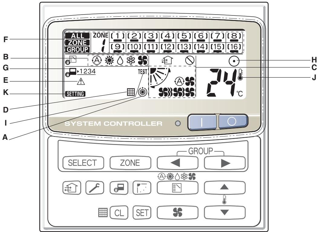
Description
A: When the unit is in the heating standby mode, the indicator appears.
B: The currently selected operation mode is displayed.
C: The currently selected FAN SPEED, Airflow Direction and SWEEP settings are displayed.
D: This indication appears when the filter needs cleaning.
E: This indication appears only when an abnormality occurs within a unit.
F: The currently selected mode (ALL, ZONE or GROUP), ZONE number and GROUP number are displayed.
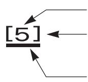
GROUP number display (no figure: no number registered)
GROUP state display ([ ] : registered group, [ ] : currently selected group)
Operation state display ( — : on, no sign: off, ≧ = : alarm)
G: The currently selected central control mode (1, 2, 3 or 4) is displayed.
H: Lights when any of the air conditioners under the central control is operating; turns off when none of the air conditioners under the central control is operating. Blinks when any conditioner is operating under abnormal conditions and its protection functionality is working.
I: This indication appears while a test run is underway.
J: This indication appears when the temperature is set.
K: When turning on the power switch of the central controller, setting sign blinks for a few minutes. While blinking, any controls using the central controller are inhibited. This is because the central controller is verifying connected groups.
How to start group operation
To start group operation
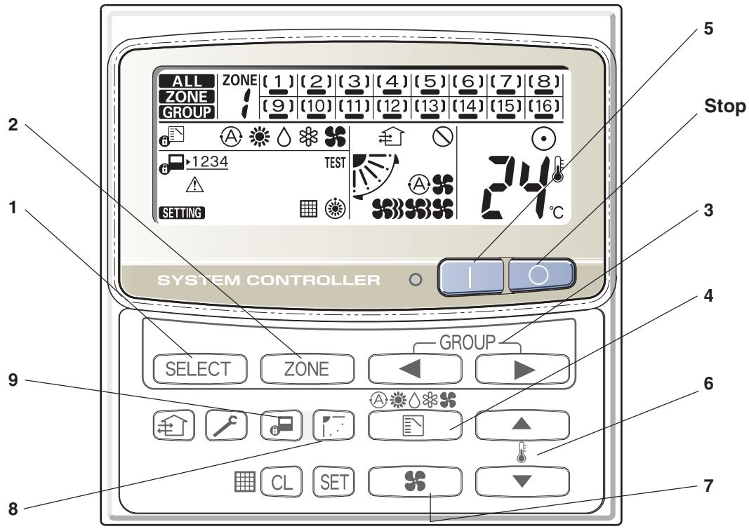
| Power | Turn the power supply switch on more than 12 hours before starting operation. |
| 1 SELECT | Press the SELECT button and select GROUP. |
| 2 ZONE | Select the ZONE No. including the group to be operated by pressing ZONE button. |
| 3 ←▶ | Select the GROUP No. to be operated by pressing GROUP select buttons ←▶. |
| 4 | Set the operation mode by pressing the MODE button. |
| 5 | Press the ON button. |
| 6 | Set the desired temperature by pressing one of the temperature setting buttons ▲▼. |
| 7 | Set the desired fan speed by pressing the FAN SPEED button. |
| 8 | Set the airflow direction to a specific angle or sweep mode. |
| 9 | By pressing ☑, select your desired setting. Individual: Controls with the remote controller are possible. Central 1: Individual ON/OFF operation with the remote controller is inhibited. Central 2: Individual ON/OFF, MODE, and Temp. setting operations with the remote controller are inhibited. Central 3: Individual MODE and Temp. setting operations with the remote controller are inhibited. Central 4: Individual MODE operation with the remote controller is inhibited. Under Central/Individual settings other than listed above, “CENTRAL” is displayed. |
| AUTO Operation | Depending on the difference between the temperature setting and the room temperature, heating and cooling alternate automatically so that a uniform room temperature is maintained. Some models are not provided with a mode for automatically setting the cooling or heating operation. |
| Stop | Confirming the GROUP No. to be selected, press the OFF button. |
NOTE
The flap setting can be performed only for units that have no remote controllers.
How to start collective operation
To start collective operation (ALL or ZONE)
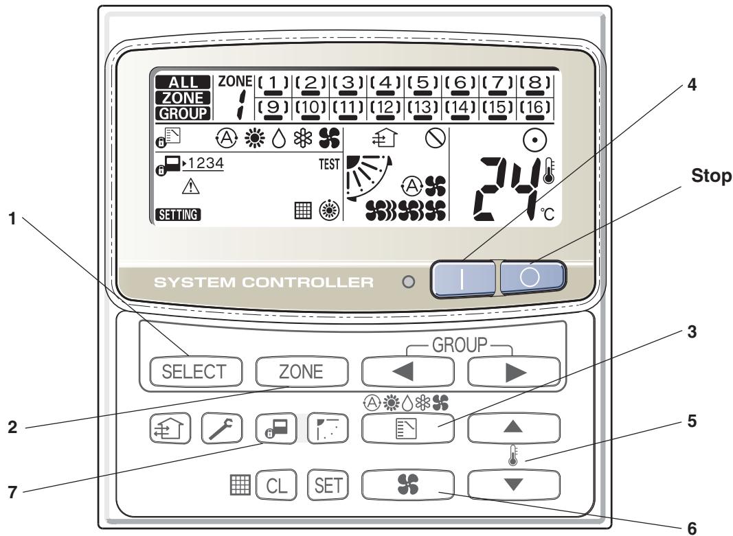
| Power | Turn the power supply switch on 12 hours or more before starting operation. |
| 1 SELECT | Press the SELECT button and select ALL or ZONE. In case of ZONE collective operation. |
| 2 ZONE | Select the ZONE No. to be operated by pressing ZONE button. |
| 3 | Set the operation mode by pressing the MODE button. |
| 4 1 | Press the ON button. |
| 5 ▲ ▼ | Set the desired temperature by pressing one of the temperature setting buttons ▲ ▼. |
| 6 ¥ | Set the desired fan speed by pressing the FAN SPEED button. |
| 7 | Select the control mode. |
| Stop | Confirming the ZONE No. to be selected or ALL indication, press the OFF button. |
NOTE
In the ALL or ZONE mode, no flap setting can be performed. If necessary, you should select the GR mode and use the FLAP button.
4-3 Application controls of indoor unit
4-3-1 Setup of selecting function in indoor unit (Be sure to Execute Setup by a Wired Remote Controller)
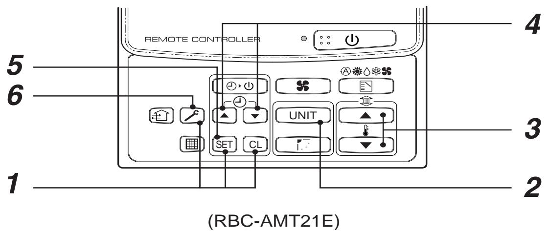
1 Push SET, CL, and f buttons simultaneously for 4 seconds or more. The firstly displayed unit No. indicates the header indoor unit address in the group control. In this time, the fan of the selected indoor unit is turned on.
2 Every pushing UNIT button, the indoor unit numbers in the group control are successively displayed. In this time, the fan of the selected indoor unit only is turned on.
3 Specify the item code (DN) using the setup temperature and buttons.
4 Select the setup data using the timer time and buttons. (When selecting the DN code to "33", change the temperature indication of the unit from "°C" to "°F" on the remote controller.)
5 Push SET button. (OK if display goes on.) To change the selected indoor unit, return to procedure 2. To change the item to be set up, return to procedure 3.
Pushing button returns the status to normal stop status.
CAUTION
Be sure to perform the item code (DN) setting as the "Cooling Only" for the cooling only indoor unit in case of heat recovery type (Super HRM). If this setting is not performed, error code [L18] may occur.
Table: Function selecting item numbers (DN)
(Items necessary to perform the applied control at the local site are described.)
| DN | Item | Description | At shipment | |
| 01 | Filter sign lighting time | 0000: None | 0001: 150H | According to type |
| 0002: 2500H | 0003: 5000H | |||
| 0004: 10000H | ||||
| 02 | Dirty state of filter | 0000: Standard | 0001: High degree of dirt (Half of standard time) | 0000: Standard |
| 03 | Central control address | 0001: No.1 unit to 0099: Unfixed | 0064: No.64 unit | 0099: Unfixed |
| 04 | Specific indoor unit priority | 0000: No priority | 0001: Priority | 0000: No priority |
| 06 | Heating temp shift | 0000: No shift | 0001: +1°C | 0002: +2°C (Floor type 0000: 0°C) |
| 0002: +2°C to | 0010: +10°C (Up to +6 recommended) | |||
| 0d | Existence of automatic cool/heat mode | 0000: Provided | 0001: Not provided (Automatic selection from connected outdoor unit) | 0001: Not provided |
| 0F | Cooling only | 0000: Heat pump | 0001: Cooling only (No display of [AUTO] [HEAT]) | 0000: Heat pump |
| 12 | Line address | 0001: No.1 unit to | 0030: No.30 unit | 0099: Unfixed |
| 13 | Indoor unit address | 0001: No.1 unit to | 0064: No.64 unit | 0099: Unfixed |
| 14 | Group address | 0000: Individual | 0001: Header unit of group | 0099: Unfixed |
| 0002: Follower unit of group | ||||
| 19 | Flap type (Adjustment of air direction) | 0000: Not provided | 0001: Swing only | According to type |
| 0004: [4-way Air Discharge Cassette type] and [Under Ceiling type] | ||||
| 1E | Temp difference of automatic cooling/heating mode selection COOL → HEAT, HEAT →COOL | 0000: 0 deg to | 0010: 10 deg (For setup temperature, reversal of COOL/HEAT by ± (Data value)/2) | 0003: 3 deg (Ts±1.5) |
| 28 | Automatic restart of power failure | 0000: None | 0001: Restart | 0000: None |
| 29 | Operation condition of humidifier | 0000: Usual | 0001: Condition ignored | 0000: Usual |
| (Detection control for heat exchanger temperature) | ||||
| 2A | Selection of option/ error input (CN70) | 0000: Filter input | 0001: Alarm input (Air washer, etc.) | 0002: Humidifier |
| 0002: Humidifier input | ||||
| 2E | HA terminal (CN61) select | 0000: Usual | 0001: Leaving-ON prevention control | 0000: Usual (HA terminal) |
| 30 | Automatic elevating grille | 0000: Unavailable | 0001: Available (Auto grille, Oil guard, Auto grille panel) | 0000: Unavailable |
| 31 | Ventilating fan control | 0000: Unavailable | 0001: Available | 0000: Unavailable |
| 32 | TA sensor selection | 0000: Body TA sensor | 0001: Remote controller sensor | 0000: Body TA sensor |
| 33 | Temperature unit select | 0000: °C (at factory shipment) | 0001: °F | 0000: °C |
| 40 | Control for humidifier (+ drain pump control) | 0000: None | 0001: Humidifier + Vaporizing system (Pump ON) | 0003: Humidifier ON, Pump OFF |
| 0002: Humidifier + Ultrasonic system (Pump ON after specified time passed) (Unused) | ||||
| 0003: Humidifier + Natural drain system (Pump OFF) | ||||
| 5d | High ceiling selection (Air volume selection) | [4-way Air Discharge Cassette type] and [Under Ceiling type] | 0000: Standard | |
| 0000: Standard filter | ||||
| 0001: Super-long life | ||||
| [Concealed Duct Standard type] | ||||
| 0000: Standard static pressure (40Pa) | 0001: High static pressure 1 (70Pa) | |||
| 0003: High static pressure 2 (100Pa) | 0005: Correspond to quiet sound 0006: Low static pressure (20Pa) | |||
| 60 | Timer set (Wired remote controller) | 0000: Available (Operable) | 0001: Unavailable (Operation prohibited) | 0000: Available |
| 62 | Smudging-proof control clear | 0000: Clear | 4- way Air Discharge Cassette type only | |
| 92 | Outside interlock release condition | 0000: Operation stop | 0001: Release communication signal receive | 0000: Operation stop |
Selection of indoor air temperature sensor
(How to select "body TA sensor" or "remote controller sensor")
Wired remote controller (RBC-AMT21E) has the sensor to detect air temperature.
Whether body TA sensor or remote controller sensor you use can be selected by item code (DN) setting from wired remote controller.
| DN | 32 | 0000 | Body TA sensor | At shipment |
| 0001 | Remote controller sensor |
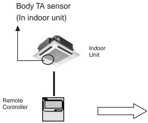
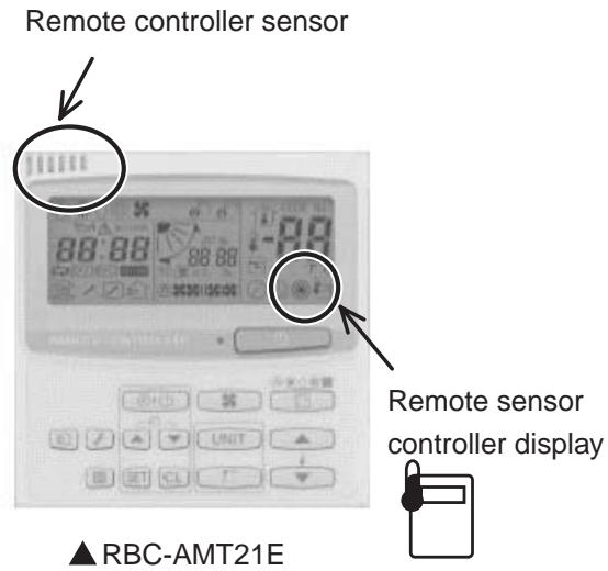
[Note]
In case of using remote sensor "TCB-TC21LE", don't select "remote controller senor" by item code (DN) setting.
![TOSHIBA TCB-SC642TLE2 - [Note] - 1](/content/2025/01/121691/images/5f81b12f9499836c28e572c453a82399833164632f5649139644bd93dc529848.jpg)
4-3-2 Ventilation fan control from remote controller
[Function]
- The start/stop operation can be operated from the wired remote controller when air to air heat exchanger or ventilating fan is installed in the system.
- The fan can be operated even if the indoor unit is not operating.
- Use a fan which can receive the no-voltage A contact as an outside input signal.
- In a group control, the units are collectively operated and they can not be individually operated.
(1) Operation
Handle a wired remote controller in the following procedure.
- Use the wired remote controller during stop of the system.
- Be sure to set up the wired remote controller to the header indoor unit. (Same in group control)
- In a group control, if the wired remote controller is set up to the header indoor unit, both header and follower units are simultaneously operable.
1 Push concurrently SET + CL + f buttons for 4 seconds or more.
The unit No. displayed firstly indicates the header indoor unit address in the group control.
In this time, the fan of the selected indoor unit turns on.
2 Every pushing UNIT button, the indoor unit numbers in group control are displayed successively.
In this time, the fan of the selected indoor unit only turns on.
3 Using the setup temp or button, specify the item code 31.
4 Using the timer time or button, select the setup data. (At shipment: 0000)
The setup data are as follows:
| Setup data | Handling of operation of air to air heat exchanger or ventilating fan |
| 0000 | Unavailable (At shipment) |
| 0001 | Available |
5 Push SET button. (OK if display goes on.)
To change the selected indoor unit, go to the procedure 2).
- To change the item to be set up, go to the procedure 3).
6 Pushing l returns the status to the usual stop status.
(2) Wiring
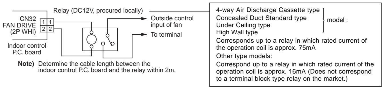
4-3-3 Leaving-ON prevention control
[Function]
- This function controls the indoor units individually. It is connected with cable to the control P.C. board of the indoor unit.
- In a group control, it is connected with cable to the indoor unit (Control P.C. board), and the item code is set to the connected indoor unit.
- It is used when the start operation from outside if unnecessary but the stop operation is necessary.
-
Using a card switch box, card lock, etc, the leaving-ON of the indoor unit can be protected.
-
When inserting a card, start/stop operation from the remote controller is allowed.
- When taking out a card, the system stops if the indoor unit is operating and start/stop operation from the remote controller is forbidden.
(1) Control items
1) Outside contact ON : The start/stop operation from the remote controller is allowed. (Status that card is inserted in the card switch box)
2) Outside contact OFF : If the indoor unit is operating, it is stopped forcibly. (Start/Stop prohibited to remote controller) (Status that card is taken out from the card switch box)
- When the card switch box does not perform the above contact operation, convert it using a relay with b contact.
(2) Operation
Handle the wired remote controller switch in the following procedure.
- Use the wired remote controller switch during stop of the system.
1 Push concurrently SET + CL + f buttons for 4 seconds or more.
2 Using the setup temp or button, specify the item code ^ .
3 Using the timer time or button, set to the setup data.
4 Push SET button.
5 Push button. (The status returns to the usual stop status.)
(3) Wiring
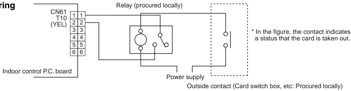
Note) Determine the cable length between the indoor control P.C. board and the relay within 2m .
4-3-4 Power peak-cut from indoor unit
When the relay is turned on, a forced thermostat-OFF operation starts.
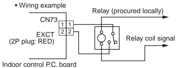
Note) Determine the cable length between the indoor or outdoor control P.C. board and the relay within 2m .
4-3-5 Remote sensor (TCB-TC21LE)
[Installation work and service]
Accessory parts
| Part Name | Q'ty | Part Name | Q'ty |
| Remote sensor (200mm-cable attached) | 1 | Spacer | 2 |
| Wire joint | 2 | ||
| Small screw M4 x 25 | 2 | Cable clampper | 1 |
| Wood screw | 2 | Installation Manual | 1 |
Requirement to install the remote sensor
Installation place
- Install the remote sensor at a position with height 1 to 1.5m from the floor, where the average temperature in the room can be felt.
- Do not install the remote sensor at a place exposed to the direct sunlight or direct outside air, such as a side of window, etc.
- Do not install the remote sensor at a place behind something or rear side of something, where air flow is poor in the room.
- Do not install the remote controller near the freezing box or refrigerator because water proof or drop-proof is not applied to this remote controller.
- Be sure to set the remote sensor vertically on the wall surface, etc.
How to install the remote sensor
NOTE 1: Avoid to twist the remote sensor cable with the power supply cable, etc. or to store them in the same metal pipe, otherwise it causes a malfunction.
NOTE 2 : Install the remote sensor apart from the generation source of noise.
NOTE 3: When noise is induced to the power source of the indoor unit, some measures such as mounting the noise filter is necessary.
- In case of using the remote sensor as a concealed type
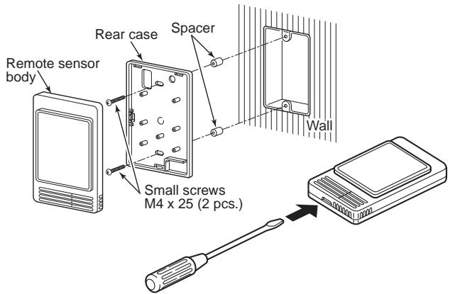
- Inserting a minus screwdriver, etc. into the groove at the lower side of the remote sensor body, force open the rear case to remove it.
- Using the attached M4 screws (2 pcs.), fix the rear case of the remote sensor. Before installation, press to open the screw hole with a screwdriver, etc.
Fix it with the spacer, but not so strongly. If the remote sensor does not fit closely to the wall, adjust it by cutting off the spacer.
- Connect the remote sensor cable (2 cores) to the terminal numbers of the indoor unit. (Applying AC 220/230/240V breaks the unit.)
- Install the remote sensor body by matching to hooks on the rear case and putting into the hooks.
How to perform cabling of the remote sensor
In case of using the remote sensor as a concealed type
- Connection diagram
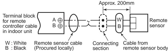
- Non polarity, 2 core cable is used..
- Use 0.5 mm^2 to 2 mm^2 cable.
| Attached wire joint (White, 2 pcs.) | Remote sensor cable Cable from remote sensor body Wire joint, CE-1 (Nichiatsu) |
| 1) Peel the sheath of the cable to be connected by approx. 14mm. 2) Twist two cables and pressure-connect them using a wire joint. 3) When an exclusive pressure-connecting tool is not used or soldering connection is used, apply insulation process with an insulation tape. |
Requirement for using the remote sensor together with the remote controller
How to install
For the above control, install the remote sensor in the following procedure.
- Set the remote controller as the master remote controller.
- Do not change the remote sensor switch in the master remote controller for correct temperature control by remote sensor.
Basic cabling diagram
- Connect cables without miswiring. (Miswiring breaks the unit.)
- In a case to operate an indoor unit from the remote sensors and the remote controller.
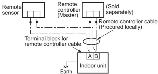
4-4 Application controls of outdoor unit
The following functions become available by setting the switches on the outdoor interface P.C. board.
| No. | Function | Switch No. | Bit |
| 1 | Outdoor fan high static pressure shift | SW10 | 2 |
| 2 | Cooling priority, Heating priority control | SW11 | 1, 2 |
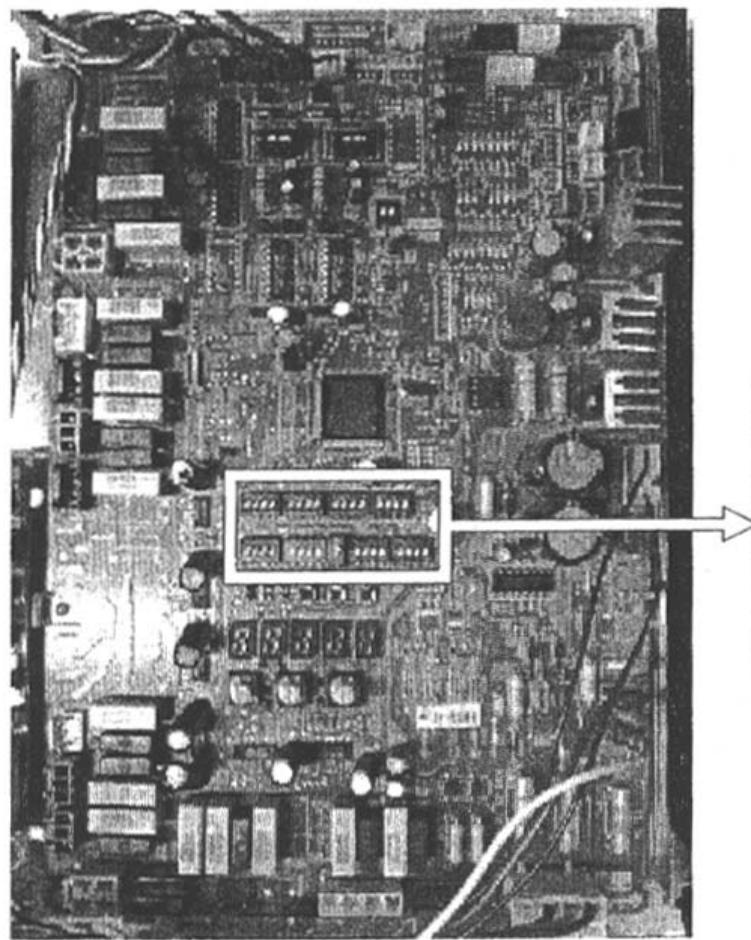
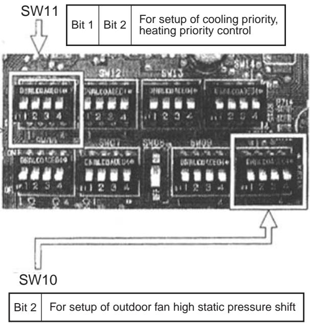
4-4-1 Outdoor fan high static pressure shift
Usage/Features
This function is set when connecting a duct to discharge port of the outdoor unit.
Setup
Turn "Bit 2" of the Dip switch [SW10] on the interface P.C. board of the outdoor unit to ON side. For the outdoor units which are connected with the ducts, set this function regardless of the header unit or follower unit.
Specifications
Increase No. of rotations of the propeller fan of the outdoor fan so that a duct with the maximum outside static pressure 35Pa (3.5mmAq) can be installed. If installing a discharge duct (Below 35Pa (3.5mmAq)) exceeding the duct resistance 15Pa (1.5mmAq), execute this setup.
Discharge air volume in each outdoor unit is described in the following table.
| Capacity rank (MMY-MAP) | 0501, 0601 type | 0801 type | 1001, 1201 type |
| Standard air volume of outdoor unit (m3/min.) | 150 | 165 | 175 |
■ Options
35Pa or more as the external static pressure is also available (Ex. 45Pa).
For details of adjustment, consult the sales subsidiary.
4-4-2 Cooling priority, heating priority control
Usage/Features
Cooling priority or heating priority can be selected.
There are the following four patterns in selecting setup of the priority mode. Select a priority mode based upon the demand of the destination to be installed.
*For Super HRM system, don't set SW11 (Leave as it is at shipment.)
Setup
(Note) In "Specific indoor unit priority" mode only, it is necessary to set up an indoor unit only which you desire to give priority. (Refer to "4-4-3".)
Outdoor unit (Header unit only) setup
| SW11 | Operation | |
| Bit 1 | Bit 2 | |
| OFF | OFF | Heating priority (Setup at shipment) |
| ON | OFF | Cooling priority |
| OFF | ON | No. of operating units (Priority is given to operation mode with which much more units operate.) |
| ON | ON | Specific indoor unit priority (Priority is given to operation mode of the indoor unit to which the operation mode priority has been set up.) |
4-4-3 Indoor unit setup in "Specific indoor unit priority" mode
① Setup switch (sw11) on interface P.C. board of header outdoor unit. (SW11 bit1=ON, bit2=ON)
(2) The setup can be changed during stop of operation. (Be sure to stop the system.)
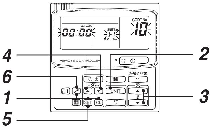
| Procedure | Operation contents |
| 1 | When pushing SET + CL + F buttons at the same time for 4 seconds or more, as shown in the figure, the display section flashes after a while confirm the displayed item code is [ 10 ]. · When the item code is one other than [ 10 ], push F button to eliminate the display and then repeat the procedure from the first step. (The remote controller operation is not accepted approx. 1 minute after pushing F button.) (In a group control, the indoor unit with number displayed firstly is set to the header unit.) |
| 2 | Every pushing UNIT, the indoor unit numbers in the group control are successively displayed. Select the indoor unit of which setup is to be changed. In this time, as the fan and louver of the selected indoor unit operate, the position of the indoor unit of which setup is to be changed can be confirmed. |
| 3 | Using the setup temperature ▲ and ▼ buttons, specify the item code [04]. |
| 4 | Using the timer time ▲ and ▼ buttons, select the setup data [0001]. Priority: 0001, No priority: 0000 |
| 5 | Push SET button. In this time, the setup operation finishes when the display changes from flashing to lighting. |
| 6 | After setup operation has finished, push F button. (Setup is determined.) When pushing F button, the display disappears and the status returns to the usual stop status. (The remote controller operation is not accepted for approx. 1 minute.) |
(NOTE)
Only one indoor unit can be set to "Priority". If the multiple indoor units are accidentally set to "Priority", an error code (L05 or L06: Duplicated indoor unit priority) is displayed.
To the unit displaying "L05", [0001 (Priority)] is setup. Separate a unit which you will give priority from the other indoor units, and return the setup data of the other indoor units to [0000 (No priority)].
| Error code | Error contents |
| L05 | Indoor unit priority duplication ([0001] is set up.) |
| L06 | Indoor unit priority duplication ([0000] is set up.) |
4-5 Application controls by optional P.C. board of outdoor unit
The following functions become available by using a control P.C. board sold separately.
Set up the switches or the header outdoor unit (U1).
| No. | Function | Switch No. | Bit | Connector No. | Used control P.C. board |
| 1 | Power peak-cut control (Standard) | SW07 | 1 | CN513 | TCB-PCDM2E |
| 2 | Power peak-cut control (Expansion) | SW07 | 1,2 | CN513 | TCB-PCDM2E |
| 3 | Snowfall fan control | — | — | CN509 | TCB-PCMO2E |
| 4 | External master ON/OFF control | — | — | CN512 | TCB-PCMO2E |
| 5 | Night operation control | — | — | CN508 | TCB-PCMO2E |
| 6 | Operation mode selection control | — | — | CN510 | TCB-PCMO2E |
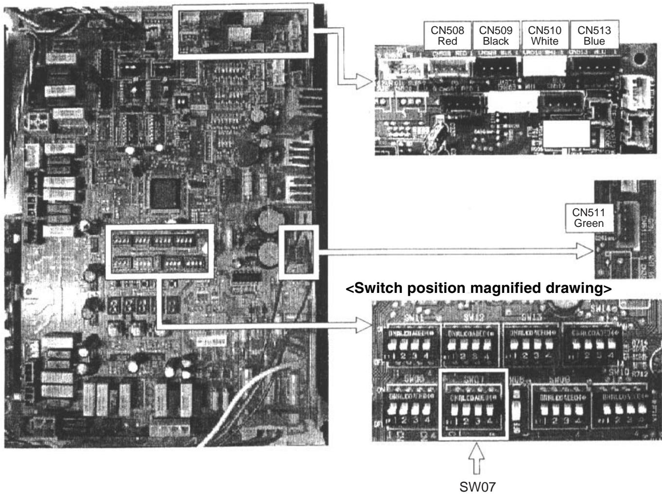
| Bit 1 | For power peak-cut control selection |
| Bit 2 | For power peak-cut control (expansion) selection |
Dimension
TCB-PCDM2E
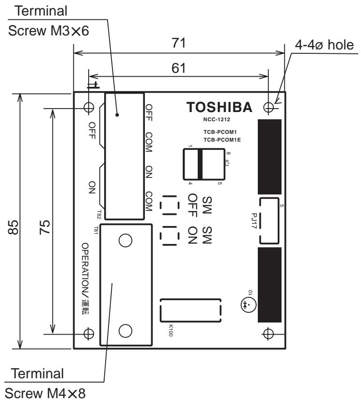
TCB-PCMO2E
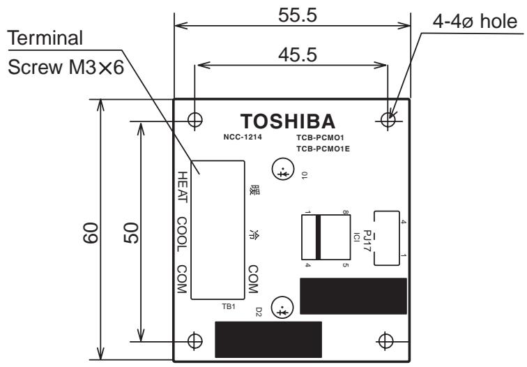
Installation procedure of power peak cut control board (TCB-PCDM2E)
1. Accessory parts
| No | Parts name | Q'ty | No | Parts name | Q'ty |
| 1 | Power peak-cut control board | 1 | 5 | Installation manual | 1 |
| 2 | Connection cable | 1 | 6 | Cable-clamp | 1 |
| 3 | Support to fix the board | 4 | 7 | Screw for cable-clamp | 1 |
| 4 | Installation manual | 1 | 8 | Banding band | 2 |
2. Placing Position
Install this P.C. board to the upper side of the inverter assembly on outdoor unit.
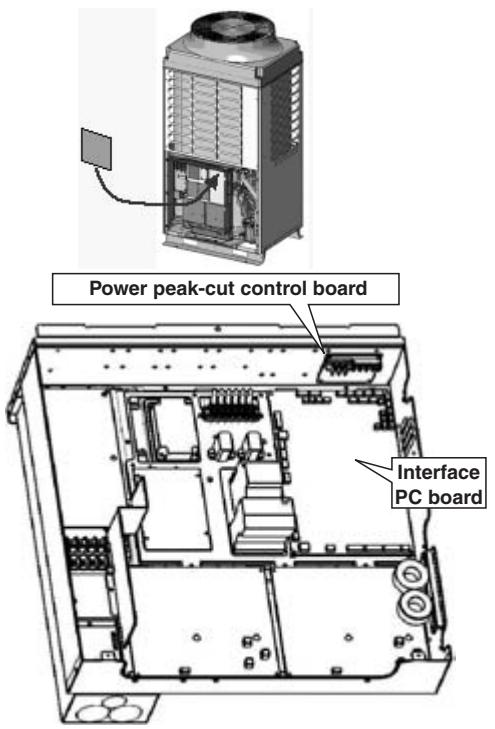
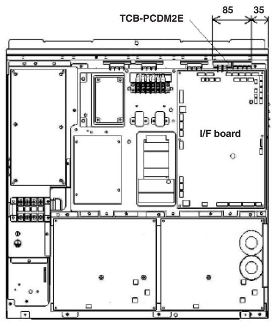
3. How to install
(1) Be sure to turn off the power when installing.
(2) Place this P.C. board by using the support to fix the board.
There are four installation holes to place the support on the upper side of the inverter assembly.
(3) Connect the P.C. board (TCB-PCDM2E) PJ17 and outdoor unit interface CN513 with connection cable.
(4) Bind the remaining cable with the attached banding band.
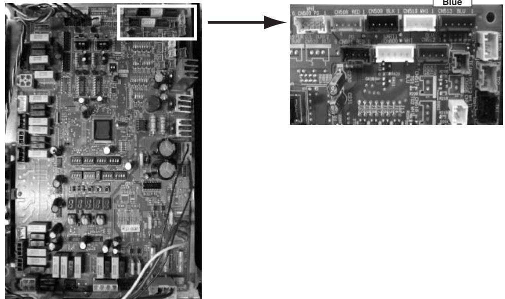
Interface P.C. board
4. wiring
| Length | Size | Type | |
| Input wiring | Up to 500m | 2-core or 3-core, 0.75mm² | Shield wire |
| Output wiring | Up to 200m | 2-core, 0.75mm²* | Shield wire |
| Up to 400m | 2-core, : 1.5mm²* |
- In conformity with design 60245 IEC 57
(1) Refer to the "Electric wiring diagram" when wiring.
(2) Be sure to use the shield wire to prevent noise trouble, and perform the grounding at both sides of shield wires.
(3) Fix the output wiring with the code clamp and banding band.
Let the output wiring into the banding band and band it together with the other wiring.
Fix the code clamp using the screw hole on the "B" position.
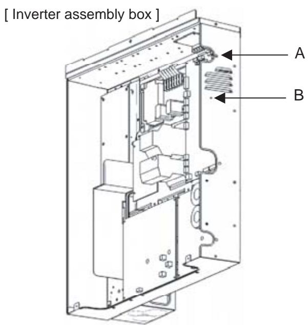
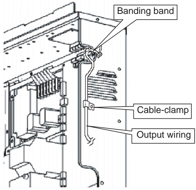
Installation procedure of external master ON/FF control board (TCB-PCMO2E)
1. Accessory Parts
| No | Parts name | Q'ty | No | Parts name | Q'ty |
| 1 | External master ON/OFF control board | 1 | 5 | Installation manual | 1 |
| 2 | Connection cable | 1 | 6 | Banding band | 1 |
| 3 | Support to fix the board | 4 | 7 | Screw for cable clamp | 1 |
| 4 | Instruction Manual | 1 |
2. Placing position
Install this P.C. board to the upper position of the inverter assembly on outdoor unit.
Up to 4 TCB-PCMO2E can be installed simultaneously in one inverter assembly.
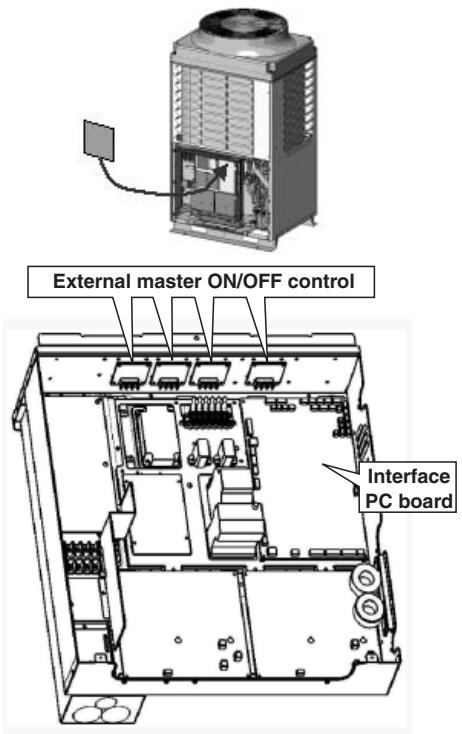
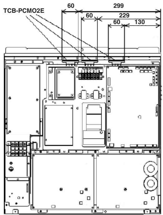
3. How to install
(1) Be sure to turn off the power when installing.
(2) Place this P.C. board by using the support to fix the board.
There are four installation holes to place the support on the upper side of the inverter assembly.
(3) Connect the PC board (TCB-PCMO2E) PJ17 and outdoor unit interface CN508 to CN512 with connection cable.
Connector on interface P.C/board is different according to the purpose.
(4) Install the P.C. board so that the terminal block becomes the interior side.
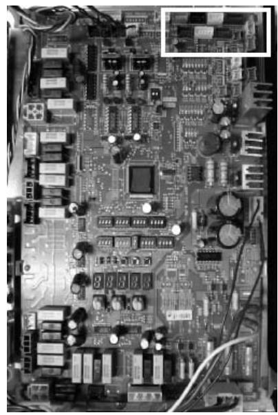
Interface P.C. board
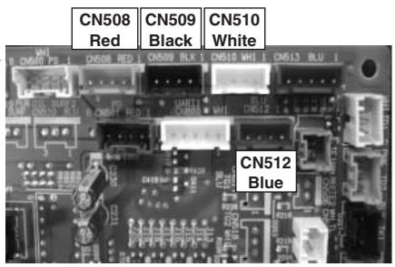
| CN508 | Night operation (sound reduction) control |
| CN509 | Snowfall fan control |
| CN510 | Operation mode selection control |
| CN512 | External master ON/OFF control |
4-5-1 Power peak-cut control (standard)
Function / Electric wiring diagram
Two type control can be selected by setting SW07 on the interface P.C. board of the header unit.
[Standard function]
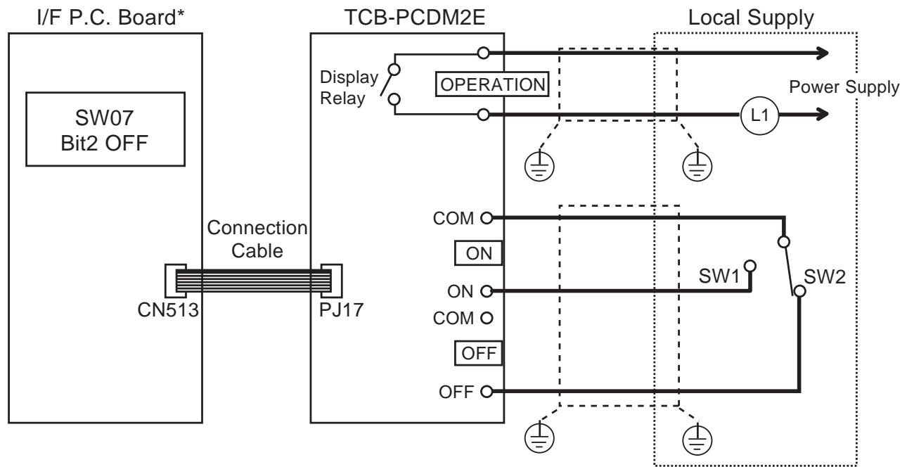
*Place this option P.C. board to header outdoor unit.
In case of pulse signal
Be sure to prepare the point of contact for each terminal.
The time of the pulse signal is more than 100msec.
Don't switch on both SW1 and SW2 terminal
simultaneously.

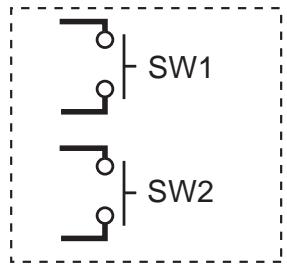
SW07-Bit2 OFF
| Input | SW07-Bit1 | Display Relay (L1) | ||
| SW1 | SW2 | Bit1 OFF | Bit1 ON | |
| OFF | ON | 100% (Normal) | 100% (Normal) | OFF |
| ON | OFF | 0% (Stop) | Up to 60% | ON |

CAUTION
Display Relay capacity of "OPERATION"
Below AC240V 0.5A (COS = 100%
When connecting load such as relay coil to "L1" load, insert the noise surge absorber.
Below DC24V 1A (Non-inductive load)
When connecting load such as relay coil to "L1" load, insert the bypass circuit.
Power peak-cut control (expansion)
[Expansion function]
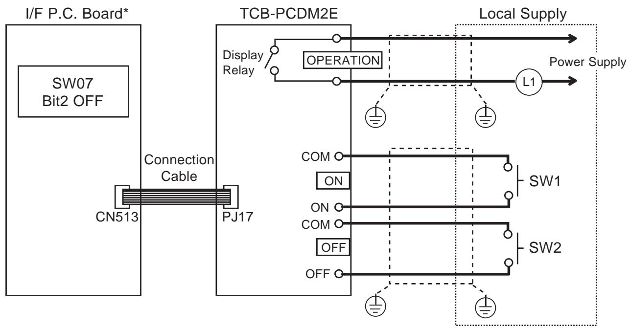
*Place this option P.C. board to header outdoor unit.
SW07-Bit2 OFF
| Input | SW07-Bit1 | Display Relay (L1) | ||
| SW1 | SW2 | Bit1 OFF | Bit1 ON | |
| OFF | OFF | 100% (Normal) | 100% (Normal) | OFF |
| ON | OFF | Up to 80% | Up to 85% | ON |
| OFF | ON | Up to 60% | Up to 75% | ON |
| ON | ON | 0% (stop) | Up to 60% | ON |

CAUTION
Display Relay capacity of "OPERATION"
Below AC240V 0.5A (COS = 100%
When connecting load such as relay coil to "L1" load, insert the noise surge absorber.
Below DC24V 1A (Non-inductive load)
When connecting load such as relay coil to "L1" load, insert the bypass circuit.
4-5-2 Snowfall fan control
Feature
Outdoor fan is operated with the snowfall signal from outside.
Function
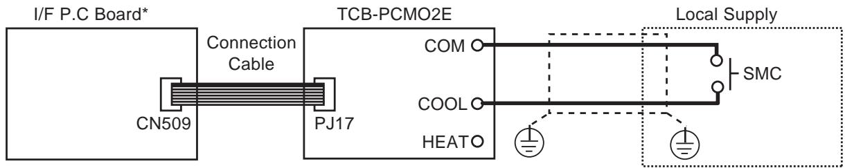
*Place this option P.C. board to header outdoor unit.
SMC: Snowfall detection switch
| Terminal | Input signal | Operation |
| COOL (SMC) | ON OFF | Snowfall fan control (Operates outdoor fan) |
| ON OFF | Normal operation |

CAUTION
Be sure to prepare a non-voltage continuation point of contact for each terminal.
4-5-3 External master ON/OFF control
Feature
The outdoor unit starts or stops the system.
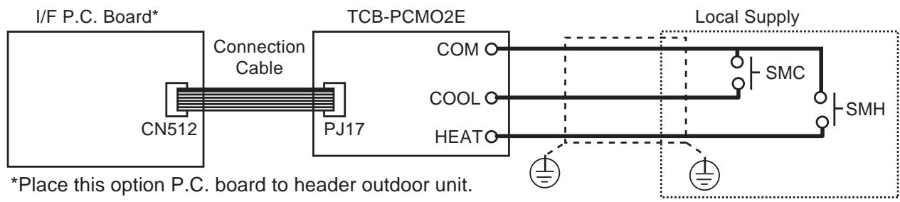
Function
SMC : Input signal for start
SMH : Input signal for stop
| Terminal | Input signal | Operation |
| COOL (SMC) | ON OFF | Starts all indoor units. |
| HEAT (SMH) | ON OFF | Stops all indoor units. |

CAUTION
Be sure to prepare non voltage pulse point of contact for each terminal.
This control is conducted when input signal stand up or fall down.
(Standing and falling status should be held for 100 m.sec. or more.)
4-5-4 Night operation control
Feature
Sound level can be reduced with connecting outdoor Interface P.C. Board by restricting compressor and fan speed.
Function
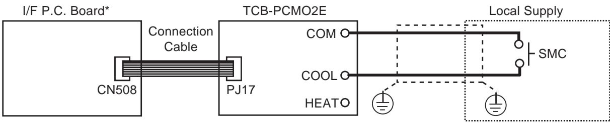
*Place this option P.C. board to header outdoor unit.
SMC : Input signal for night operation
| Terminal | Input signal | Operation |
| COOL (SMC) | ON OFF | Night operation control |
| ON OFF | Normal Operation |

CAUTION
Be sure to prepare a non-voltage continuation point of contact for each terminal.
4-5-5 Operation mode selection control
Feature
This control can be operated with the operation mode which is permitted by SMC or SMH.
Function
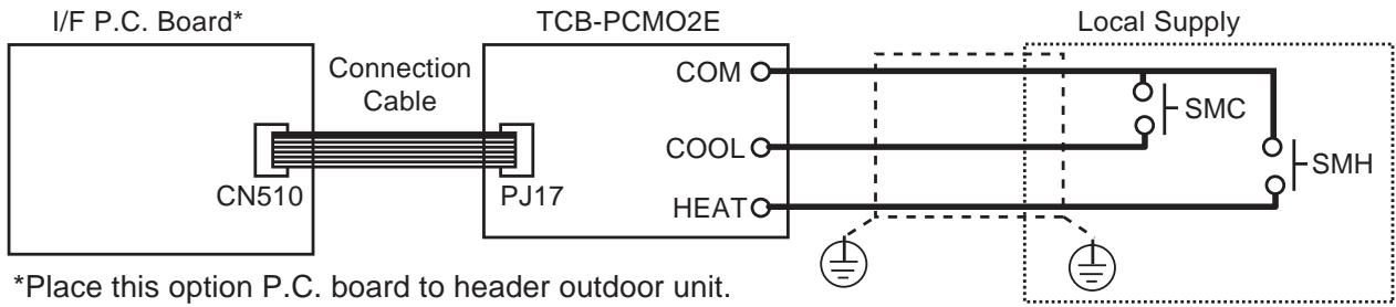
SMC : Cooling mode designated input switch
SMH : Heating mode designated input switch
| Terminal | Selected operation mode | Note | |
| COOL (SMC) | HEAT (SMH) | ||
| ON | OFF | Only cooling mode permitted | *1 |
| OFF | ON | Only heating mode permitted | *1 |
| OFF | OFF | Normal Operation | |
Note
*1 “ ” mark is indicated on the RC display.

CAUTION
Be sure to prepare non voltage continuous point of contact for each terminal.
4-6 Application controls by optional devices connected to indoor unit
4-6-1 Remote control by "remote location ON/OFF control box"
Remote location ON/OFF control box (TCB-IFCB-4E)
[Wiring and setup]
- Use the exclusive connector for connection with the indoor control P.C. board.
- In a group control, the system can operate when connecting with any indoor unit (Control P.C. board) in the group. However when taking out the operation/errorsignal from the other unit, it is necessary to take out from each unit individually.
(1) Control items
1) Start/Stop input signal : Operation start/stop in unit
2) Operation signal : Output during normal operation
3) Error signal : Output during alarm (Serial communication error or indoor/outdoor protective device) operation
(2) Wiring diagram using remote control interface (TCB-IFCB-4E)
Input IFCB-4E: No voltage ON/OFF serial signal
Output No voltage contact for operation, error display
Contact capacity: Below Max. AC240V 0.5A
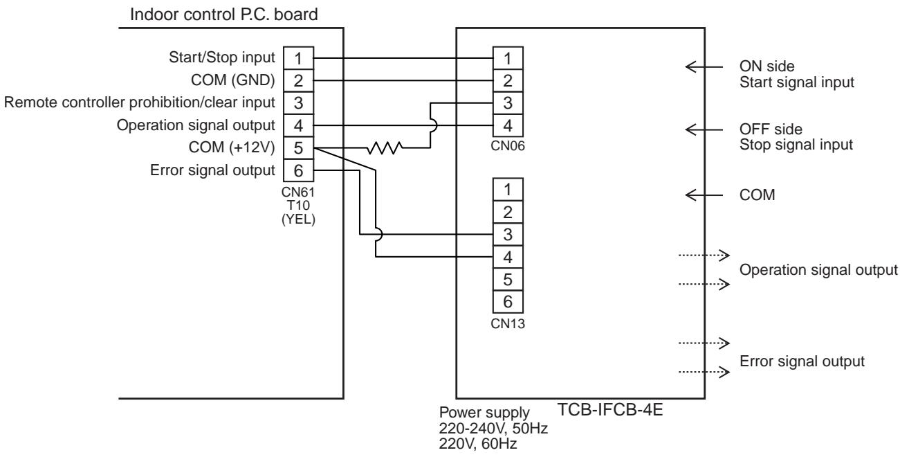
NAME :Remote location ON/OFF Control box
Model Name:TCB-IFCB-4E
Usage/Function/Characteristics
Start and Stop of the air conditioner is possible by the external signal, and also indication of operation/alarm to outside is possible.
Monitoring
The following monitoring are corresponded to output by non-voltage contact.
1) ON/OFF status (for indoor unit)
2) Alarm status (System & indoor unit stop)
ON/OFF command
Air conditioner can be turned ON/OFF by the external signals.
The external ON/OFF signals are output for the signals on the right.
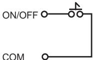
TCB-IFCB-4E Non-voltage ON/OFF continuous signal (Dry contact)
Specifications
- Central priority mode and Last-push priority modes
A select switch to select central priority mode (CENTRAL) or last-push priority mode (LAST-PUSH) is provided to this interface. Select one according to the purpose.
Central priority mode :
- Air conditioner starts operation when the external signal is ON, and then ON/OFF of air conditioner by local remote controller are possible.
- Air conditioner stops operation when the external signal is OFF, and then ON/OFF of air conditioner by local remote controller are not possible.
Last-push priority mode :
- ON/OFF of the air conditioner are possible by the external signals or the latest command from the local remote controller. (Mode enabled to turn on/off the air conditioner by the local remote controller even if the external signal is OFF)
| Name | Remote location ON/OFF control box | Status output signal | Non-voltage contact (For indication of ON/OFF status, and alarm) Contact capacity: Max. AC 240V 0.5A or less |
| Model name | TCB-ICCB-4E | ||
| Power supply | Single phase, 220-240V, 50 Hz 220V, 60Hz | Cabinet material | Galvanized steel |
| Size/Weight | 66 (height) x 170 (width) x 200 (depth) (mm)/1050g | ||
| No. of connected indoor units | 1 to 16 units for 1 interface (Group connection for 2 or more connected units) | ||
| Installation method | Exposed installation on specified position of indoor unit, appropriate position on wall surface or ceiling | ||
| Ambient temperature/humidity | 0℃ to 40℃ DB, 30% to 90% RH | ||
| Receive signal type of central ON/OFF command | Non-voltage ON/OFF continuous signal | Accessory | Shield wire cable with both-end connectors for CN06 and CN13 connector: 1.5m x 2 |
Outside view
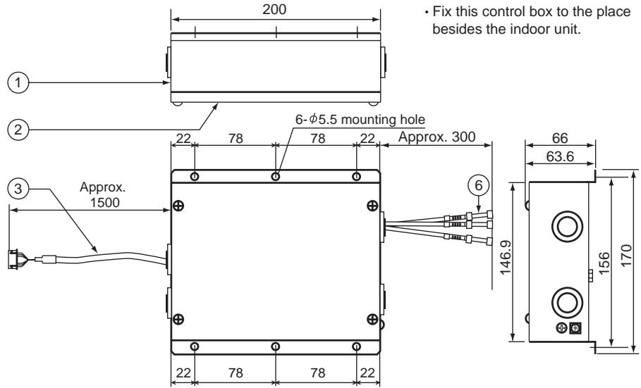
Inside view
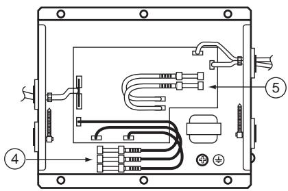
(NOTE) Do not install the accessory parts at the following locations.
- Location where combustible gas may leak
- Location where direct sunlight shines
- Location with much humidity such as bathroom, kitchen, etc.
- Location with much dust
- Location where rain or dew drops such as outdoors or under the eaves
- Location in 1m-range of TV or radio
| No. | Name | Specification |
| 1 | Case unit | Galvanized steel 0.8t |
| 2 | Case cover | Galvanized steel 0.8t |
| 3 | Harness to connect indoor unit P.C. board | CN61 connector |
| 4 | Harness for indication cable | UL1015 AWG18 tip-insulation type butt connector |
| 5 | Harness for power supply | 3-core, 0.75mm² |
| 6 | Harness for ON/OFF command | UL1015 AWG18 tip-insulation type butt connector |
Accesory parts
- Accessory No.1 connecting cables are already built in.
| No. | Name | Q'ty | Remarks |
| 1 | Cable (For CN61 connector, with 6P connectors to both ends, L=1.5m) | 1 pcs. | Connected to connector CN61 on P.C. board of indoor unit |
| 2 | M4 tapping screw | 4 pcs. | For installation of this control box |
Performance/Electric cabling diagram
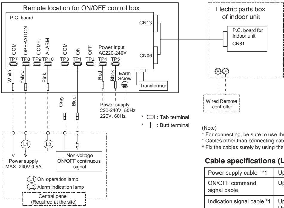
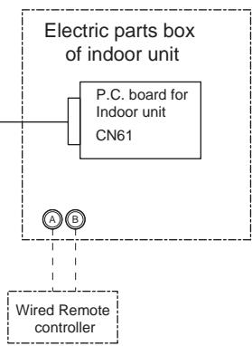
(Note)
For connecting, be sure to use the attached cables.
Cables other than connecting cables should be required at the site.
* Fix the cables surely by using the holes for fixation.
Cable specifications (Local supply)
| Power supply cable *1 | Up to 80m : 3-core, 0.75mm2 |
| ON/OFF command signal cable | Up to 500m : 2-core or 3-core, 0.75mm2 |
| Indication signal cable *1 | Up to 200m : 3-core, 0.75mm2 Up to 400m : 3-core, 1.5mm2 |
*1) In conformity with design 60245 IEC 57
- Selecting of Central priority/Last-push priority
The select switch has been previously set to LAST-PUSH side on shipment from the factory.
When using the air conditioner with central priority, remove the cover of interface adapter, and select "CENTRAL" side of the select switch (SW 1) at near the center of P.C. board.
(CAUTION)
Be sure to turn off the power supply of interface adapter before selecting one side on the select switch.
- Wiring method
(1) Power supply cable, earth, and indication signal cable must be connected in this control box. Detach the lid of the control box, and connect the cables with the terminal according to the purpose.
(2) Be sure to fix the cable with the cable clamp.
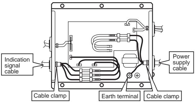
Notes on connecting relays
(Relays are used for central indication in order to prevent malfunction by surge absorber.)
a. To drive induction load with DC power
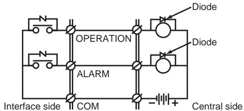
(Note)
Mount diodes to the both ends of the relay coil.
Select a diode of which back voltage tightness is 10 times or more of the use voltage, and forward current is more than the load current.
b. To drive induction load with AC power
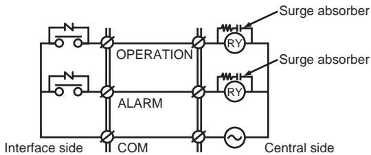
(Note)
Mount surge absorbers to both ends of the relay coil. Use a surge absorber of which voltage tightness is 350V AC/500V DC or more.
4-6-2 Central control by AI-NETWORK (Network adapter)
[Installation Manual]
1. Components
| Part name | Q'ty | Description |
| P.C. board | 1 | P.C. board corresponded to the network |
| Relay terminal block | 1 | 2P (X, Y) terminal block for relay |
| Relay cable (A) | 1 | For connection of adapter board with X, Y relay terminal block (Red connector) |
| Relay cable (B) | 1 | For connection of adapter board with remote controller terminal block (Blue connector) |
| Installation Manual | 1 | This manual |
| Spacer (A) | 2 | For fixing the adapter P.C. board (Used for other types than 4-way cassette type) |
| Spacer (B) | 1 | For fixing the adapter P.C. board (Used for other types than 4-way cassette type) |
| Spacer (C) | 3 | For fixing the adapter P.C. board (Used for 4-way cassette type) |
| Screws to fix terminal block | 2 | For fixing the relay terminal block (M4 x 14 ) |
| Transformer cover | 1 | Used to store transformer (For 4-way cassette type) |
| Transformer base | 1 | Used to store transformer (For 4-way cassette type) |
| Transformer | 1 | For supplying power to adapter |
| Screws to fix transformer | 2 | For fixing transformer (M3 x 6 ) |
| Screws to assemble transformer cover | 2 | For assembling transformer cover (M4 x 6 for 4-way) |
| Screws to fix transformer base | 2 | For fixing transformer base (M4 x 10 for 4-way) |
| Bundling band | 3 | Used to process cables so that they are not caught in. |
2. Combination List of Adapter Parts
| Parts | For 4-way air discharge cassette type | For Concealed duct standard type | |
| 1 | Adapter P.C. board | 3 spacers (C) for installing P.C. board | 2 spacers (A) for installing P.C. board 1 spacer (B) for installing P.C. board |
| 2 | Transformer | M3 x 6 B tight screw (2 pcs.) | M3 x 6 B tight screw (2 pcs.) |
| 3 | For assembling transformer cover | M4 x 6 tapping screws (2 pcs.) | —— |
| 4 | For fixing transformer base | M4 x 10 plus tight screws (2 pcs.) | —— |
| 5 | XY terminal block | M4 x 14 tapping tight screws (2 pcs.) | M4 x 14 tapping tight screws (2 pcs.) |
| 6 | Adapter P.C. board to XY terminal block | Connector, red color, lead length : 600L | Connector, red color, lead length : 600L |
| 7 | Adapter P.C. board to AB terminal block | Connector, blue color, lead length : 600L | Connector, blue color, lead length : 600L |
- Spacer (A) for installing P.C. board : Spacer to be mounted by using the hole on the P.C. board. (For other types than 4-way cassette type)
Spacer (B) for installing P.C. board : Spacer to be mounted by pinching it in the P.C. board.
(For other types than 4-way cassette type)
Spacer (C) for installing P.C. board : Spacer to be mounted by using the hole on the P.C. board for 4-way cassette type. - For other indoor unit type, refer to the installation manual attached this adapter.
3. Connection of Cables
[1] Connection of network cables
- Attach one network adapter to a group of one group controlling (including one unit).
Connect the network adapter to any one of the indoor units in the group control.
![TOSHIBA TCB-SC642TLE2 - [1] Connection of network cables - 1](/content/2025/01/121691/images/71503aabc8b460a1c96a3ccfebe670312ecbf70c0bec145f58acbcc18f2a0b0d.jpg)
Connectable indoor units per group : Up to 8 units (In case of 1-remote controller system*)
- In case of 2-remote controllers system, up to 7 indoor units are allowable to be connected.
[2] Cabling diagram of indoor control P.C. board
For details, see the installation procedure for individual model.
![TOSHIBA TCB-SC642TLE2 - [2] Cabling diagram of indoor control P.C. board - 1](/content/2025/01/121691/images/26c5eeae1f9128620dddad3cb88984f0505ae2dbc248ce70c3f4594624dfa36f.jpg)
- The enclosed section with the chain line includes the attached parts.
- There is no polarity for cabling to the terminal blocks, A, B and X, Y.
- Arrange the total cable length of the remote controller cable and the inter-unit cable of the remote controller within 400m.
4. Installation Procedure
- For installation of the adapter P.C. board and removal of the relay cable, be sure to wait for a while (approx. 1 minute) after turning off the power supplies of the air conditioner and the collective control remote controller. If not doing so, the adapter P.C. board may be damaged.
In case of 4-way Air Discharge Cassette type*
| No. | Procedure |
| 1 | Using the spacer (C), install the adapter P.C. board to the position of the electric parts box of the indoor unit. |
| 2 | Using the 2 pcs. Ø4 x 14 tapping tight screws, install X, Y relay terminal block to the position of the electric parts box. · When tightening the screws, be sure not to damage the cable. |
| 3 | Using 2 pcs. Ø4 x 6 tapping screws, install the transformer box storing the transformer to the position at side of the bell mouth. |
| 4 | Using the relay cable (A), connect the X, Y relay terminal block with CN03 (Red) of the adapter P.C. board, and remote controller terminal block (A, B) with CN02 (Blue) of the adapter P.C. board using the relay cable (B), respectively. Perform cabling between the yellow connector of the transformer and CN309 of the adapter P.C. board, and between white connector to CN01 of the adapter P.C. board, respectively. |
| Details | |
| Adapter TCB-PCNT20E sold separately | |
| Adapter TCB-PCNT20E sold separately | |
| Network adapter P.C. board CN02 (Blue) CN03 (Red) CN309 (Yellow) Spacer (C) Relay cable (B) A, B terminal block for remote controller Transformer box * To install the adapter P.C. board to the electric parts box, put 3 pcs. spacer (C) into the hole of the P.C. board. * After connection of the relay cables (A) and (B), fix them along the neighboring cables with bundling band so that cables are not caught. | |
- For other indoor unit type, refer to installation manual attached this adapter.
5. Setup of the Address No.
To connect the indoor unit to the central remote controller using the adapter, it is necessary to set up the network address No.
-
It is required to agree the network address No. with the central remote controller system No.
-
The network address No. is set to 1 at the shipment from the factory.
The following two methods are used for setup.
1. Setup from the remote controller at the indoor unit side (RBC-AMT21E)
- This method is available only when [7] of the setup switch SW01 on the adapter P.C. board is OFF.
Set up the address No. while the air conditioner stops.
1 Push and buttons for 4 seconds or more.
In case of the group control, the unit No. RLL is displayed, and then all the indoor units in the group control are selected. (Fig. 1)
In this time, the fans of all the selected indoor units start and the swing operation also starts in the models with flaps.
(Keep the display status of RLL without pushing UNIT button.)
In case of individual remote controller with no group control, the system address and the indoor unit address are displayed.
2 Using / buttons, specify the item code 13.
3 Using 一 buttons, select the setup data.
The following table shows the setup data. (Table 1)
4 Push SET button.
(When the display goes on, the setup data is accepted.)
To change the setup item, return to the step 2.
5 Push button. The status returns to the normal stop status.
(Table 1)
| Setup data | Network address No. |
| 0001 | 1 |
| 0002 | 2 |
| 0003 | 3 |
| · | · |
| · | · |
| 0064 | 64 |
| 0099 | No setting (Shipment from the factory.) |
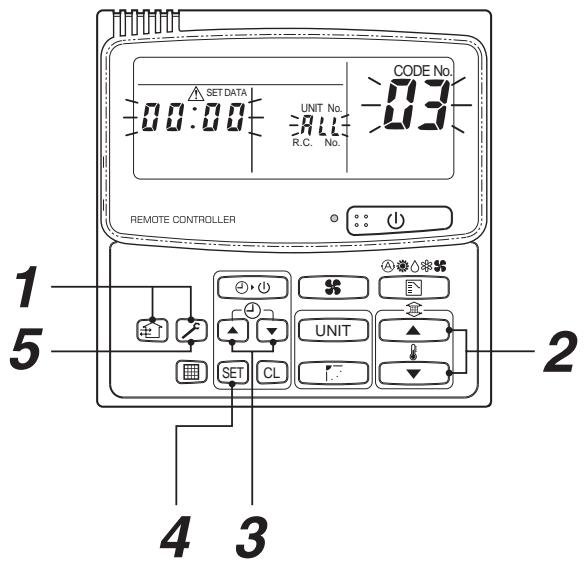
(Fig. 1)
2. Setup by the switch on the adapter P.C. board
When the remote controller is not found, or when you do not want to change the setup of network address No. on the remote controller, set up the address No. by using the setup switch SW01 (Network address No. setup switch) on the adapter P.C. board.
1 Turn off the power supply.
2 Set [7] of the address No. setup switch SW01 to ON side.
Accordingly, the setup of the address No. from the remote controller is invalidated. (Fig. 2)
3 The network address No. is set up by combining ON/OFF of the address No. setup switch, from SW01 [6] to [1].
For the relation between ON/OFF combination and the address No., see (Table 2).
A case when the address No. is set to 16 is shown in (Fig. 3).
![TOSHIBA TCB-SC642TLE2 - The network address No. is set up by combining ON/OFF of the address No. setup switch, from SW01 [6] to [1]. - 1](/content/2025/01/121691/images/f7adc73dee4816e17c7c7fabc344a9dc2f4f4d613edc5e7244b019ff4bafd735.jpg)
Address No. setup on the remote controller is invalid.
(Fig. 2)
![TOSHIBA TCB-SC642TLE2 - The network address No. is set up by combining ON/OFF of the address No. setup switch, from SW01 [6] to [1]. - 2](/content/2025/01/121691/images/ba548bb34dd75530838707aeb07c8a24f056fa7961426e8a9daa4bc4de183911.jpg)
(Fig. 3)
When the network address No. has been changed, turn on the power of the central remote controller again or reset the central remote controller from the reset hole on the control panel of the central remote controller.
(Table 2)
ON side, × OFF side
Requirement in Service Time
When using this product as the service part for change of the adapter P.C. board, be sure to set the setup switch SW01 (Network address No. setup switch) on the adapter P.C. board so that it is same as one before change.
6. To Customers
Cautions in using the remote controller
- After all the power supplies of the air conditioner have been turned on, turn on the power supply of the central remote controller. (16-systems : RBC-CR1-PE, 64-systems : RBC-CR64-PE)
If the power supplies of the air conditioner and the remote controller are turned on at the same time, or if they are turned on in reverse order, the check code [97] may be temporarily displayed on the central remote controller. When the connection cabling and setup of the central address are correct, the connected air conditioner is displayed on the central remote controller.
- As described below, there are differences of the display on LCD and the individual restrictions for the operation in the main wired remote controller (RBC-AMT21E) and the central remote controller.
| Item | Contents | Cautions | ||
| Main remote controller | Central remote controller | |||
| 1 | Fan speed select | A#B### | A### | Display of air speed selection differs. |
| 2 | Fan speed select in FAN mode | ### | A### | When operating the main remote controller, A### is not displayed. If selecting A### at the central side, A### is displayed on the main remote controller. In this time, the air speed is ###. |
| 3 | Fan speed select in DRY mode | A### | A### | A### only is displayed on the central remote controller. A### is displayed on the main remote controller even by change of the setup temperature/lover, and the air speed changes automatically. |
| 4 | Air direction adjustment | ### and air direction adjustment | [LOUVER] | [LOUVER] only is displayed on the central remote controller. [LOUVER] is displayed when the flap is swinging, and ON and OFF of the swing operation set to the louver are exchanged. |
| (No display) | [LOUVER] Manual | Set the air direction on the main remote controller. | ||
| 5 | Check button | Test run (4 seconds) | Display of check code and Check reset (3 seconds) | In case of type without function of air direction adjustment The function differs when the button is pushed for a long time. If the central remote controller-ON is reset during operation of the air conditioner, the operation stops temporarily, and then the operation is resumed. (Trouble of the air conditioner is cleared.) |
| 6 | Check code | Display with 3 digits (Alphabet + 2 digits numerals) | Display with 2 digits (Alphabet or numerals) | The display of the check code differs. Ex.) Float switch operation Main side : [P10], Collective side : [0b] |
- When using the remote controller with the former remote controller (RBC-AM1E, AT1E), if Last-push priority/Center/Locked is selected on the central remote controller, the display differs on the main remote controller.
| Item | Contents | Remarks | ||
| New remote controller (RBC-AMT21E) | Former remote controller (RBC-AM1E, AT1E) | |||
| 1 | Last-push priority | (No display) | (No display) | All the setups and Start/Stop operation are available. |
| 2 | Center | CENTER goes on. | CENTER goes on. | The setup contents of the central remote controller are fixed, and the Start/Stop operation and timer operation are available on the main remote controller. |
| 3 | Locked | CENTER flashes. | The setup contents of the central remote controller are fixed, and the air conditioner stops. The operation on the main remote controller is unavailable. | |
- Before using the remote controller, read the Owner's Manual thoroughly to use it correctly.
4-6-3 Central control with "1:1 model" ("1:1 model" connection interface)
- When controlling the super-digital inverter and the digital inverter, the adapter named "1:1 model" connection interface (TCB-PCNT30TLE) is necessary.
- Central control device must be connected to central control wiring.
- In case of central control among 1:1 models, be sure to set SW01-1 to ON in the system with the least line address number. (At shipment : SW01-1=OFF)
1. Cabling connection of control wiring
Attach an adapter per 1 group in group control operation (including individual control). Connect the adapter to the header indoor unit in the group control.
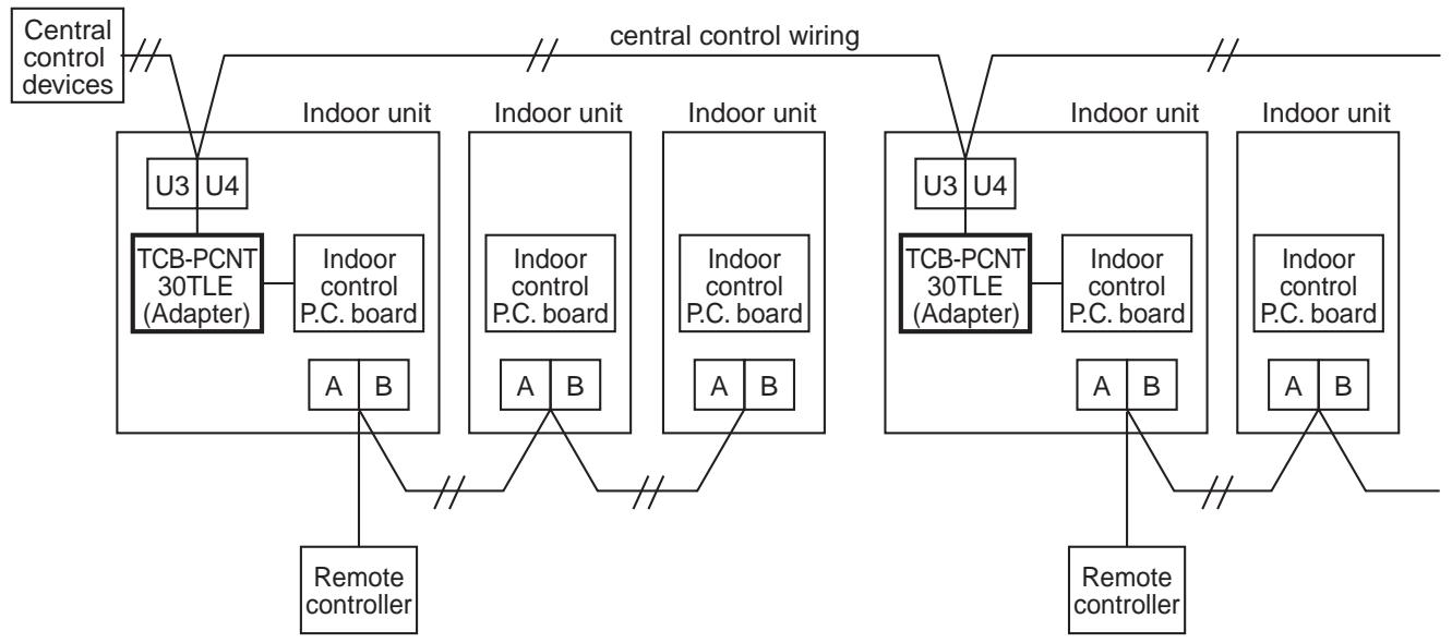
2. Cabling connection diagram with indoor control P.C board
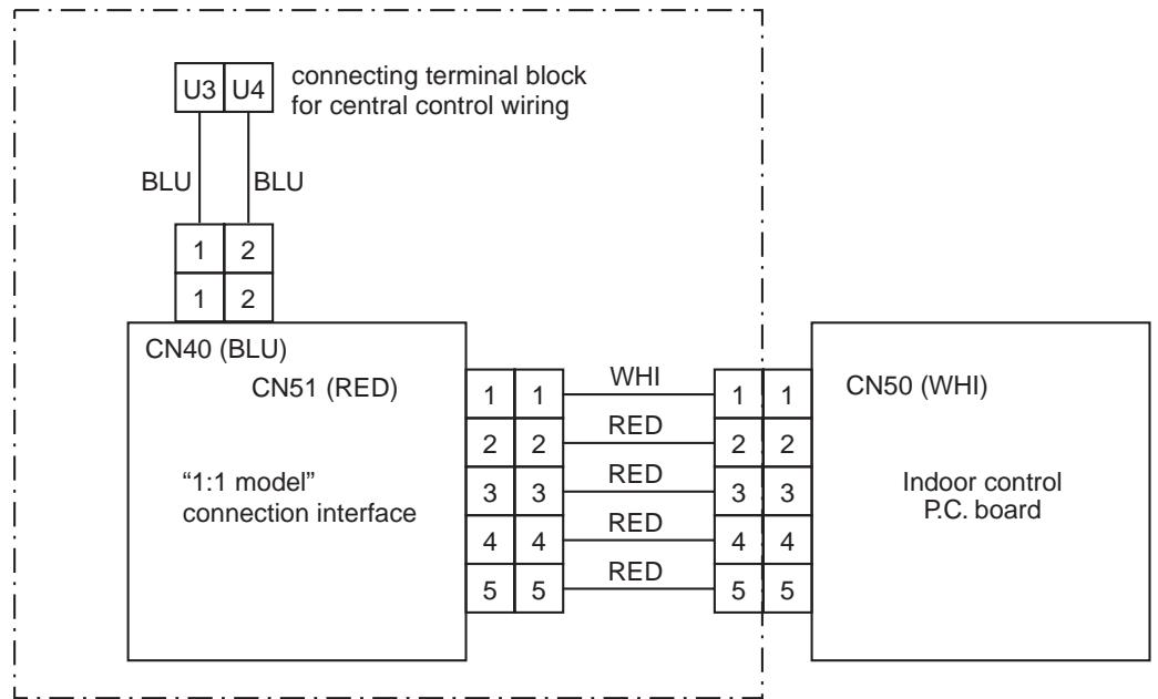
- Parts included in the single-point chain line are optional accessories.
- There is non-polarity on the cables connected to U3 and U4 terminals.
3. Switch Setting on the P.C. board
In case of central control among 1:1 models, setting of the terminator resistor.*
Terminator resistor is set by SW01.
- Be sure to set the terminal resistor on the P.C. board connected the indoor unit with the least line address.
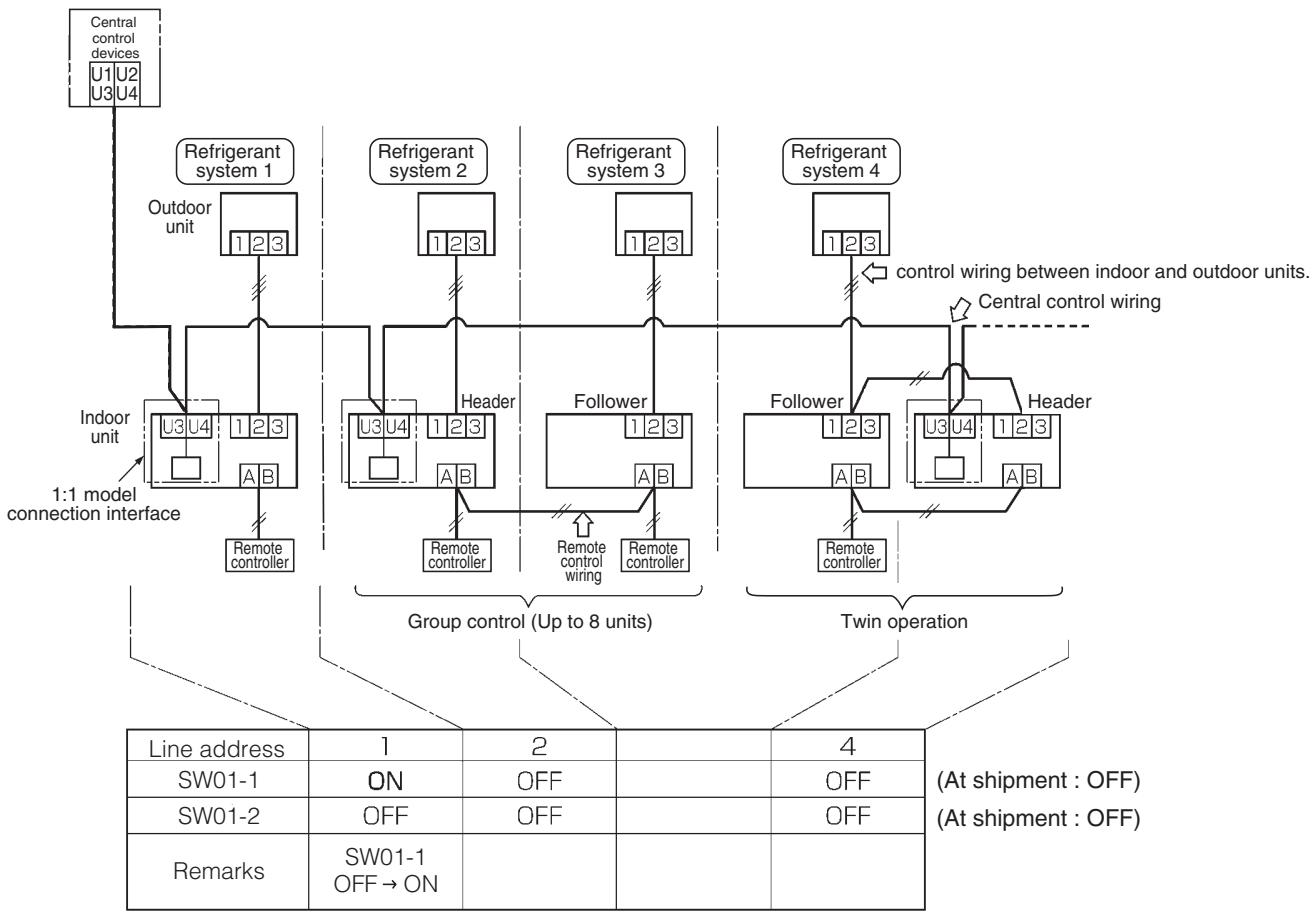
(Reference) Setting contents of the switch (SW01)
| SW01 | Terminator resistor | Remarks | |
| bit 1 | bit 2 | ||
| OFF | OFF | no terminator | At shipment, combined system with VRF system. |
| ON | OFF | 100Ω | Central control among 1:1 models |
*) If the central control is conducted with VRF systems, set the terminator resister (SW30-2) on the header outdoor unit with the least line address number to ON on VRF system, and set up SW30-2 of the other header units to OFF. (Refer to the section of "3-2-2".)
In this case, setting of the terminator resister on 1:1 models is unnecessary. (Remain SW01 as it is at shipment.)
4. Installation Procedure
- For installation of the adapter P.C. board and removal of the relay cable, be sure to wait a while (approx. 1 minute) after turning off the power supplies of the air conditioner and the collective control remote controller. If not doing so, the adapter P.C. board may be damaged.
In case of 4-way Air Discharge Cassette Type
| No. | Procedure |
| 1 | Using the spacer (A), install the adapter P.C. board to the position of the electric parts box. |
| 2 | Install U3, U4 relay terminal block to the position of the electric parts box. ·When tightening the screws, be sure not to damage the cable. |
| 3 | Using the relay cable (A), connect the U3, U4 relay terminal block with CN40 (BLU) on the adapter P.C. board. Using the relay cable (B), connect CN50 (WHI) on the indoor P.C. board with CN51 (RED) on the adapter P.C. board. |
| Details | |
TCB-PCNT30TL
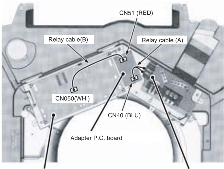
Indoor P.C. board
U3,U4 relay terminal block
- Relay cable (A)
Connection between U3, U4 relay terminal block and CN40 (BLU) on the adapter P.C. board.
Connection cables in no polar. - Relay cable (B)
Connection between CN50 (WHI) on the indoor P.C. board and CN51 (RED) on the adapter P.C. board. -
To install the adapter P.C. board to the electric parts box, put 3 pcs. Spacer (A) into the hole of the P.C. board.
-
After connection of the relay cables (A) and (B), fix them along the neighboring cables with bundling band so that cables are not caught.
-
For other indoor unit type, refer to the installation manual attached this adapter.
5. Address set up
Outline
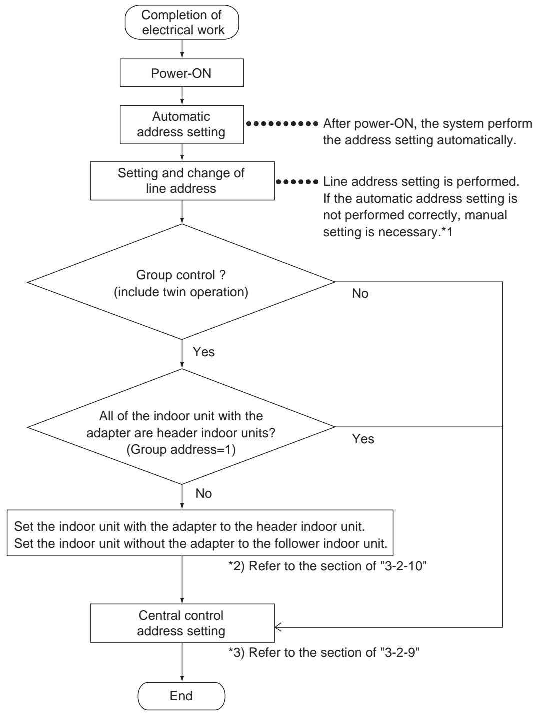
*1) After automatic address setup, all the line address become "1" except a group control and then a duplicated address error "E08" is output. It is necessary to change the line address from the wired remote controller for each system. (Refer to the section of "3-2-10".)
For detailed procedure, refer to the installation manual attached this adapter.
DIMENSIONAL DRAWING
Wired remote controller
RBC-AMT21E
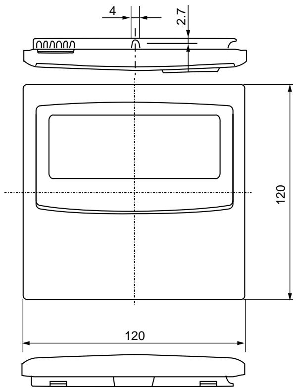
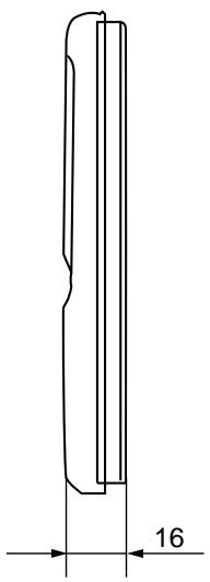
Simple remote controller
RBC-AS21E
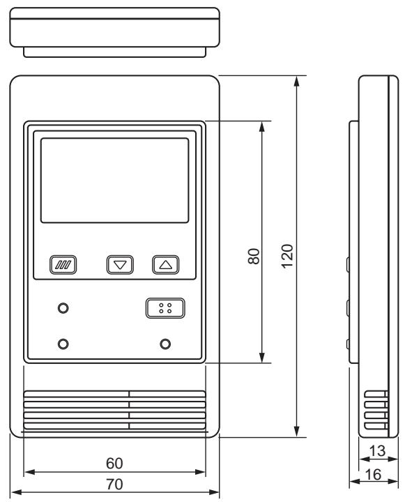
Wireless remote controller kit
TCB-AX21U(W)-E
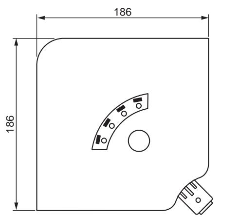
32
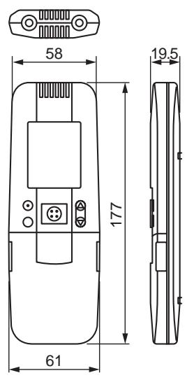
Wireless remote controller kit
RBC-AX22CE
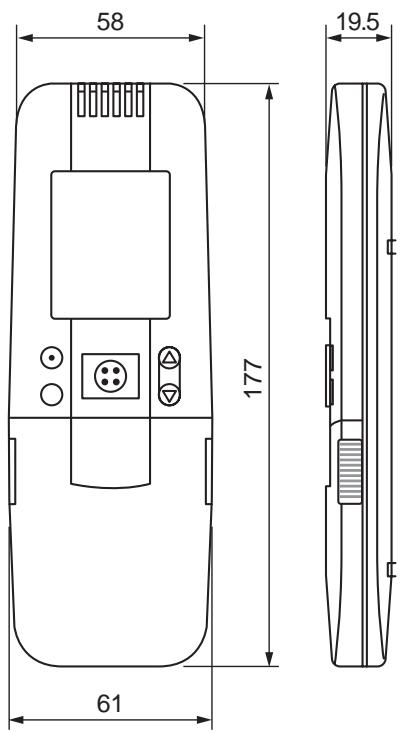
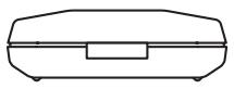
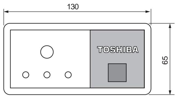
Wireless remote controller kit
TCB-AX21E
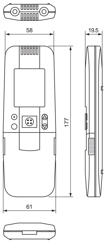
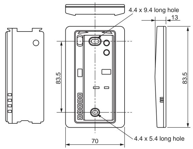
Weekly timer
RBC-EXW21E
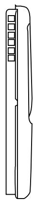
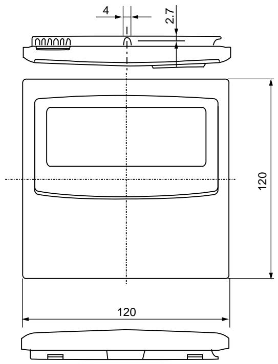
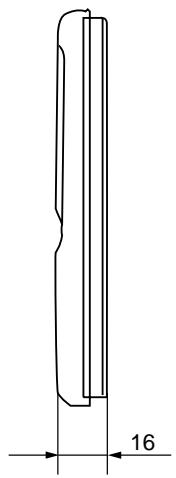
Central remote controller
TCB-SC642TLE
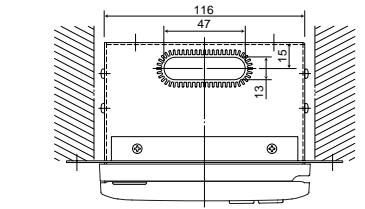
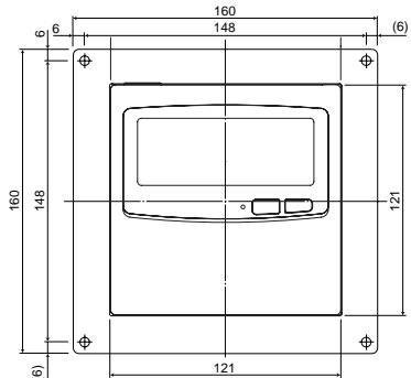
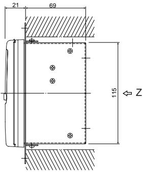
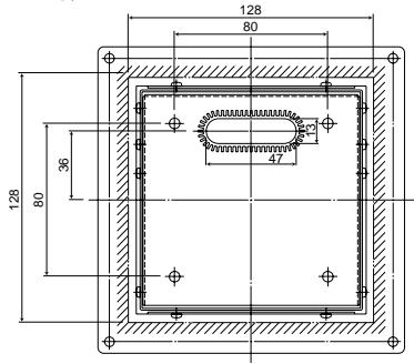
Z-view
LON Gateway
TCB-IFLN**
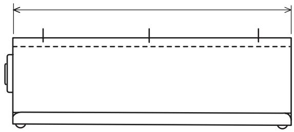
- Detailed dimensions were not available at the time of publication.
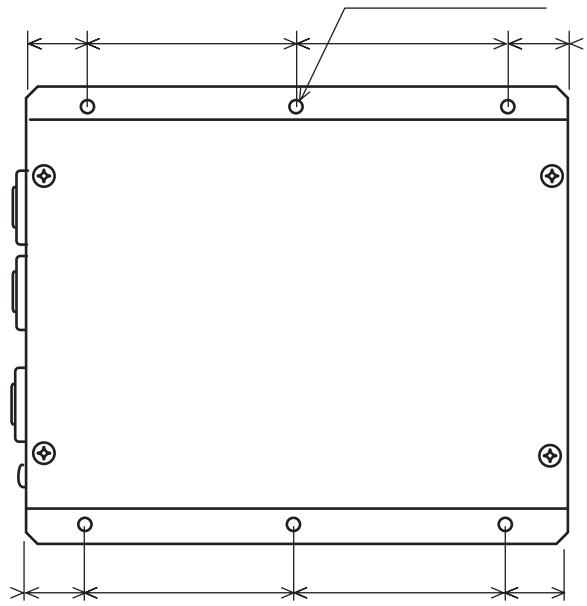
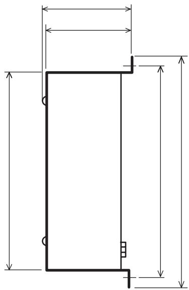
TCS-Net Relay Interface
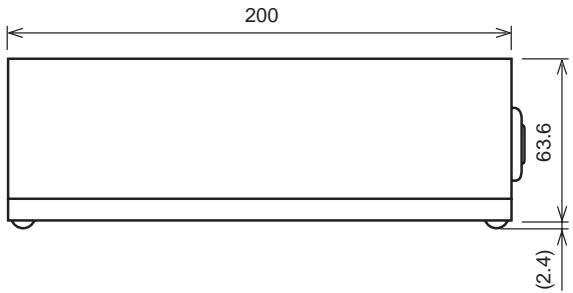
BMS-IFLSV1E
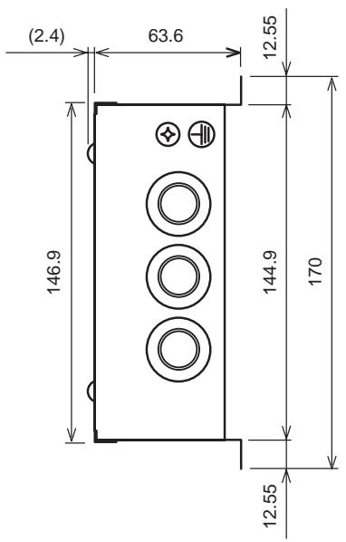
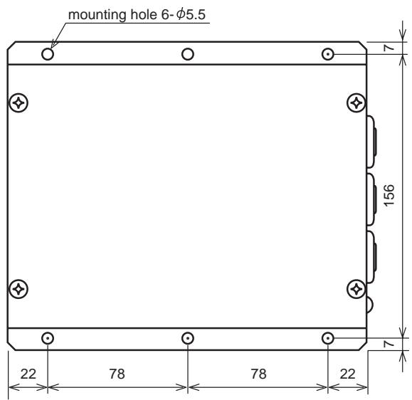
Touch Screen Controller
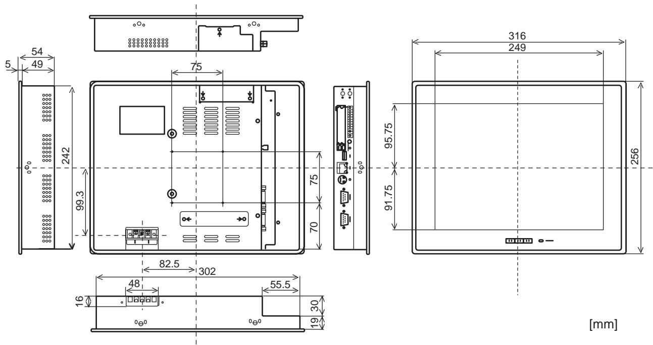
BMS-TP5120ACE
Intelligent Server
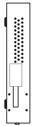
BMS-LSV2E
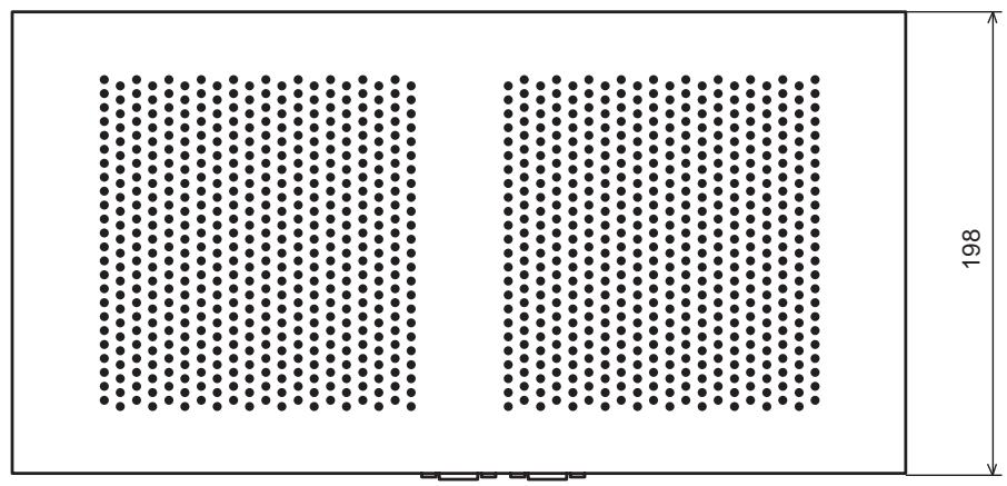
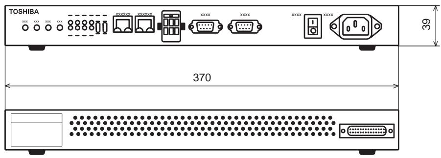
Energy Monitoring Relay Interface

BMS-IFWH3E
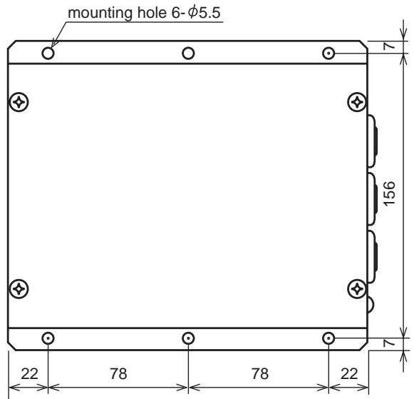
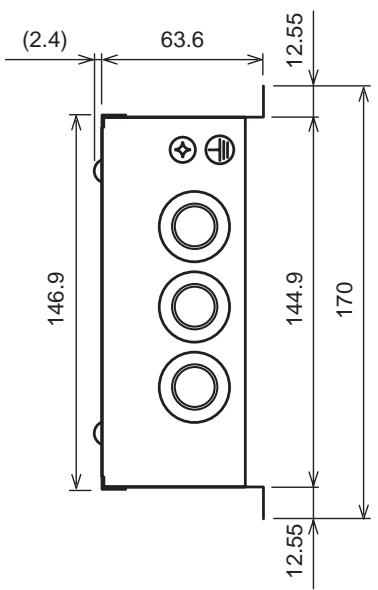
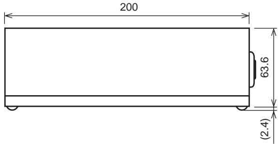
Digital I/O Relay Interface
BMS-IFDD01E
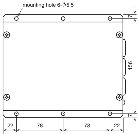
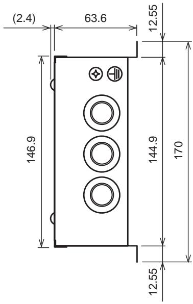
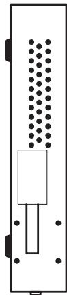
WINDOWS based central controller
BMS-LSV**