
RAV-SP1604AT8-E - Air-conditioner TOSHIBA - Free user manual and instructions
Find the device manual for free RAV-SP1604AT8-E TOSHIBA in PDF.

User questions about RAV-SP1604AT8-E TOSHIBA
0 question about this device. Answer the ones you know or ask your own.
Ask a new question about this device
Download the instructions for your Air-conditioner in PDF format for free! Find your manual RAV-SP1604AT8-E - TOSHIBA and take your electronic device back in hand. On this page are published all the documents necessary for the use of your device. RAV-SP1604AT8-E by TOSHIBA.
USER MANUAL RAV-SP1604AT8-E TOSHIBA
AIR-CONDITIONER SPLIT TYPE
OUTDOOR UNIT
RAV-SP1104AT8-E
RAV-SP1104AT8Z-E
RAV-SP1104AT8ZG-E
RAV-SP1404AT8-E
RAV-SP1404AT8Z-E
RAV-SP1404AT8ZG-E
RAV-SP1604AT8-E
RAV-SP1604AT8Z-E
RAV-SP1604AT8ZG-E
RAV-SP1104AT8-TR
RAV-SP1104AT8Z-TR
RAV-SP1104AT8ZG-TR
RAV-SP1404AT8-TR
RAV-SP1404AT8Z-TR
RAV-SP1404AT8ZG-TR
RAV-SP1104AT7
RAV-SP1104AT7Z
RAV-SP1104AT7ZG
RAV-SP1404AT7
RAV-SP1404AT7Z
RAV-SP1404AT7ZG
RAV-SP1604AT7
RAV-SP1604AT7Z
RAV-SP1604AT7ZG
CONTENTS
ORIGINAL INSTRUCTION 3
WARNING INDICATIONS ON THE AIR CONDITIONER UNIT 5
PRECAUTION FOR SAFETY 6
NEW REFRIGERANT (R410A) 11
1. SPECIFICATIONS 13
1-1. Indoor Unit 13
1-2. Outdoor Unit 29
1-3. Operation Characteristic Curve 30
2. CONSTRUCTION VIEWS (EXTERNAL VIEWS) 32
2-1. Outdoor Unit 32
3. OUTDOOR UNIT REFRIGERATING CYCLE DIAGRAM 35
4. WIRING DIAGRAM 36
4-1. Outdoor Unit 36
5. SPECIFICATIONS OF ELECTRICAL PARTS 37
5-1. Outdoor Unit 37
6. REFRIGERANT R410A 38
6-1. Safety During Installation/Servicing 38
6-2. Refrigerant Piping Installation 38
6-3. Tools 42
6-4. Recharging of Refrigerant 42
6-5. Brazing of Pipes 43
6-6. Instructions for Re-use Piping of R22 or R407C 45
7. CIRCUIT CONFIGURATION AND CONTROL SPECIFICATIONS 48
7-1. Outdoor Unit Control 48
7-2. Outline of Main Controls 52
8. TROUBLESHOOTING 57
8-1. Summary of Troubleshooting 57
8-2. Troubleshooting 59
9. SETUP AT LOCAL SITE AND OTHERS 82
9-1. Calling of Error History 82
9-2. Group Control Operation 82
9-3. Outdoor Unit 84
10. ADDRESS SETUP 91
10-1. Address Setup Procedure 91
10-2. Address Setup & Group Control 92
10-3. Remote Controller Wiring 95
10-4. Address Setup (Manual setting from remote controller) 96
10-5. Confirmation of Indoor Unit No. Position 97
11. REPLACEMENT OF THE SERVICE P.C. BOARD (4316V392) MCC-1599 99
12. HOW TO EXCHANGE COMPRESSOR 100
12-1. Exchanging Procedure of Compressor (Outline) 100
12-2. Exchange of Compressor 100
13. INSTALLATION MANUAL 101
14. DETACHMENTS 118
14-1. Outdoor Unit 118
15. EXPLODED VIEWS AND PARTS LIST 130
15-1. Outdoor Unit 130
Original instruction
Please read carefully through these instructions that contain important information which complies with the "Machinery" Directive (Directive 2006/42/EC), and ensure that you understand them.
Some of the details provided in these instructions differ from the service manual, and the instructions provided here take precedence.
Generic Denomination: Air Conditioner
Definition of Qualified Installer or Qualified Service Person
The air conditioner must be installed, maintained, repaired and removed by a qualified installer or qualified service person.
When any of these jobs is to be done, ask a qualified installer or qualified service person to do them for you.
A qualified installer or qualified service person is an agent who has the qualifications and knowledge described in the table below.
| Agent | Qualifications and knowledge which the agent must have |
| Qualified installer (*1) | ·The qualified installer is a person who installs, maintains, relocates and removes the air conditioners made by Toshiba Carrier Corporation. He or she has been trained to install, maintain, relocate and remove the air conditioners made by Toshiba Carrier Corporation or, alternatively, he or she has been instructed in such operations by an individual or individuals who have been trained and is thus thoroughly acquainted with the knowledge related to these operations. ·The qualified installer who is allowed to do the electrical work involved in installation, relocation and removal has the qualifications pertaining to this electrical work as stipulated by the local laws and regulations, and he or she is a person who has been trained in matters relating to electrical work on the air conditioners made by Toshiba Carrier Corporation or, alternatively, he or she has been instructed in such matters by an individual or individuals who have been trained and is thus thoroughly acquainted with the knowledge related to this work. ·The qualified installer who is allowed to do the refrigerant handling and piping work involved in installation, relocation and removal has the qualifications pertaining to this refrigerant handling and piping work as stipulated by the local laws and regulations, and he or she is a person who has been trained in matters relating to refrigerant handling and piping work on the air conditioners made by Toshiba Carrier Corporation or, alternatively, he or she has been instructed in such matters by an individual or individuals who have been trained and is thus thoroughly acquainted with the knowledge related to this work. ·The qualified installer who is allowed to work at heights has been trained in matters relating to working at heights with the air conditioners made by Toshiba Carrier Corporation or, alternatively, he or she has been instructed in such matters by an individual or individuals who have been trained and is thus thoroughly acquainted with the knowledge related to this work. |
| Qualified service person (*1) | ·The qualified service person is a person who installs, repairs, maintains, relocates and removes the air conditioners made by Toshiba Carrier Corporation. He or she has been trained to install, repair, maintain, relocate and remove the air conditioners made by Toshiba Carrier Corporation or, alternatively, he or she has been instructed in such operations by an individual or individuals who have been trained and is thus thoroughly acquainted with the knowledge related to these operations. ·The qualified service person who is allowed to do the electrical work involved in installation, repair, relocation and removal has the qualifications pertaining to this electrical work as stipulated by the local laws and regulations, and he or she is a person who has been trained in matters relating to electrical work on the air conditioners made by Toshiba Carrier Corporation or, alternatively, he or she has been instructed in such matters by an individual or individuals who have been trained and is thus thoroughly acquainted with the knowledge related to this work. ·The qualified service person who is allowed to do the refrigerant handling and piping work involved in installation, repair, relocation and removal has the qualifications pertaining to this refrigerant handling and piping work as stipulated by the local laws and regulations, and he or she is a person who has been trained in matters relating to refrigerant handling and piping work on the air conditioners made by Toshiba Carrier Corporation or, alternatively, he or she has been instructed in such matters by an individual or individuals who have been trained and is thus thoroughly acquainted with the knowledge related to this work. ·The qualified service person who is allowed to work at heights has been trained in matters relating to working at heights with the air conditioners made by Toshiba Carrier Corporation or, alternatively, he or she has been instructed in such matters by an individual or individuals who have been trained and is thus thoroughly acquainted with the knowledge related to this work. |
Definition of Protective Gear
When the air conditioner is to be transported, installed, maintained, repaired or removed, wear protective gloves and 'safety' work clothing.
In addition to such normal protective gear, wear the protective gear described below when undertaking the special work detailed in the table below.
Failure to wear the proper protective gear is dangerous because you will be more susceptible to injury, burns, electric shocks and other injuries.
| Work undertaken | Protective gear worn |
| All types of work | Protective gloves “Safety” working clothing |
| Electrical-related work | Gloves to provide protection for electricians and from heat Insulating shoes Clothing to provide protection from electric shock |
| Work done at heights (50 cm or more) | Helmets for use in industry |
| Transportation of heavy objects | Shoes with additional protective toe cap |
| Repair of outdoor unit | Gloves to provide protection for electricians and from heat |
The important contents concerned to the safety are described on the product itself and on this Service Manual. Please read this Service Manual after understanding the described items thoroughly in the following contents (Indications/llustrated marks), and keep them.
[Explanation of indications]
| Indication | Explanation |
| DANGER | Indicates contents assumed that an imminent danger causing a death or serious injury of the repair engineers and the third parties when an incorrect work has been executed. |
| WARNING | Indicates possibilities assumed that a danger causing a death or serious injury of the repair engineers, the third parties, and the users due to troubles of the product after work when an incorrect work has been executed. |
| CAUTION | Indicates contents assumed that an injury or property damage (*) may be caused on the repair engineers, the third parties, and the users due to troubles of the product after work when an incorrect work has been executed. |
- Property damage : Enlarged damage concerned to property, furniture, and domestic animal/pet
[Explanation of illustrated marks]
| Mark | Explanation |
| ⊗ | Indicates prohibited items (Forbidden items to do) The sentences near an illustrated mark describe the concrete prohibited contents. |
| ! | Indicates mandatory items (Compulsory items to do) The sentences near an illustrated mark describe the concrete mandatory contents. |
| △ | Indicates cautions (Including danger/warning) The sentences or illustration near or in an illustrated mark describe the concrete cautious contents. |
Warning Indications on the Air Conditioner Unit
[Confirmation of warning label on the main unit]
Confirm that labels are indicated on the specified positions
If removing the label during parts replace, stick it as the original.
| Warning indication | Description | |
| 警告 | WARNING | WARNING ELECTRICAL SHOCK HAZARD Disconnect all remote electric power supplies before servicing. |
| ELECTRICAL SHOCK HAZARD Disconnect all remote electric power supplies before servicing. | ||
| 警告 | WARNING | WARNING Moving parts. Do not operate unit with grille removed. Stop the unit before the servicing. |
| Moving parts. Do not operate unit with grille removed. Stop the unit before the servicing. | ||
| 警告 | CAUTION | CAUTION High temperature parts. You might get burned when removing this panel. |
| High temperature parts. You might get burned when removing this panel. | ||
| 警告 | CAUTION | CAUTION Do not touch the aluminum fins of the unit. Doing so may result in injury. |
| Do not touch the aluminum fins of the unit. Doing so may result in injury. | ||
| 警告 | CAUTION | CAUTION BURST HAZARD BURST HAZARD Open the service valves before the operation, otherwise there might be the burst. |
| BURST HAZARD Open the service valves before the operation, otherwise there might be the burst. | ||
Precaution for Safety

WARNING
| General | Before starting to repair the air conditioner, read carefully through the Service Manual, and repair the air conditioner by following its instructions. |
| Only qualified service person (*1) is allowed to repair the air conditioner. Repair of the air conditioner by unqualified person may give rise to a fire, electric shocks, injury, water leaks and/or other problems. | |
| Only a qualified installer (*1) or qualified service person (*1) is allowed to carry out the electrical work of the air conditioner. Under no circumstances must this work be done by an unqualified individual since failure to carry out the work properly may result in electric shocks and/or electrical leaks. | |
| Wear protective gloves and safety work clothing during installation, servicing and removal. | |
| When connecting the electrical wires, repairing the electrical parts or undertaking other electrical jobs, wear gloves to provide protection for electricians and from heat, insulating shoes and clothing to provide protection from electric shocks. Failure to wear this protective gear may result in electric shocks. | |
| Use wiring that meets the specifications in the Installation Manual and the stipulations in the local regulations and laws. Use of wiring which does not meet the specifications may give rise to electric shocks, electrical leakage, smoking and/or a fire. | |
| Only a qualified installer (*1) or qualified service person (*1) is allowed to undertake work at heights using a stand of 50 cm or more or to remove the intake grille of the indoor unit to undertake work. | |
| When working at heights, use a ladder which complies with the ISO 14122 standard, and follow the procedure in the ladder's instructions. Also wear a helmet for use in industry as protective gear to undertake the work. | |
| When working at heights, put a sign in place so that no-one will approach the work location, before proceeding with the work. Parts and other objects may fall from above, possibly injuring a person below. | |
| Do not touch the aluminum fin of the outdoor unit. You may injure yourself if you do so. If the fin must be touched for some reason, first put on protective gloves and safety work clothing, and then proceed. | |
| Do not climb onto or place objects on top of the outdoor unit. You may fall or the objects may fall off of the outdoor unit and result in injury. | |
| When transporting the air conditioner, wear shoes with additional protective toe caps. | |
| When transporting the air conditioner, do not take hold of the bands around the packing carton. You may injure yourself if the bands should break. | |
| This air conditioner has passed the pressure test as specified in IEC 60335-2-40 Annex EE. |

DENGER
| Turn off breaker. | Before carrying out the installation, maintenance, repair or removal work, be sure to set the circuit breaker to the OFF position. Otherwise, electric shocks may result. |
| Before opening the intake grille of the indoor unit or service panel of the outdoor unit, set the circuit breaker to the OFF position. Failure to set the circuit breaker to the OFF position may result in electric shocks through contact with the interior parts. Only a qualified installer (*1) or qualified service person (*1) is allowed to remove the intake grille of the indoor unit or service panel of the outdoor unit and do the work required. | |
| Before starting to repair the outdoor unit fan or fan guard, be absolutely sure to set the circuit breaker to the OFF position, and place a “Work in progress” sign on the circuit breaker. | |
| When cleaning the filter or other parts of the indoor unit, set the circuit breaker to OFF without fail, and place a “Work in progress” sign near the circuit breaker before proceeding with the work. | |
| Execute discharge between terminals. | Even if the circuit breaker has been set to the OFF position before the service panel is removed and the electrical parts are repaired, you will still risk receiving an electric shock. For this reason, short-circuit the high-voltage capacitor terminals to discharge the voltage before proceeding with the repair work. For details on the short-circuiting procedure, refer to the Service Manual. You may receive an electric shock if the voltage stored in the capacitors has not been sufficiently discharged. |
| Prohibition | Place a “Work in progress” sign near the circuit breaker while the installation, maintenance, repair or removal work is being carried out. There is a danger of electric shocks if the circuit breaker is set to ON by mistake. |
| Stay on protection | If, in the course of carrying out repairs, it becomes absolutely necessary to check out the electrical parts with the electrical parts box cover of one or more of the indoor units and the service panel of the outdoor unit removed in order to find out exactly where the trouble lies, wear insulated heat-resistant gloves, insulated boots and insulated work overalls, and take care to avoid touching any live parts. You may receive an electric shock if you fail to heed this warning. Only qualified service person (*1) is allowed to do this kind of work. |

WARNING
| Check earth wires. | Before troubleshooting or repair work, check the earth wire is connected to the earth terminals of the main unit, otherwise an electric shock is caused when a leak occurs.If the earth wire is not correctly connected, contact an electric engineer for rework. |
| After completing the repair or relocation work, check that the ground wires are connected properly. | |
| Be sure to connect earth wire. (Grounding work) Incomplete grounding causes an electric shock. Do not connect ground wires to gas pipes, water pipes, and lightning rods or ground wires for telephone wires. | |
| Prohibition of modification. | Do not modify the products.Do not also disassemble or modify the parts. It may cause a fire, electric shock or injury. |
| Use specified parts. | When any of the electrical parts are to be replaced, ensure that the replacement parts satisfy the specifications given in the Service Manual (or use the parts contained on the parts list in the Service Manual). Use of any parts which do not satisfy the required specifications may give rise to electric shocks, smoking and/or a fire. |
| Do not bring a child close to the equipment. | If, in the course of carrying out repairs, it becomes absolutely necessary to check out the electrical parts with the electrical parts box cover of one or more of the indoor units and the service panel of the outdoor unit removed in order to find out exactly where the trouble lies, place "Keep out" signs around the work site before proceeding. Third-party individuals may enter the work site and receive electric shocks if this warning is not heeded. |
| Insulating measures | Connect the cut-off lead wires with crimp contact, etc, put the closed end side upward and then apply a water-cut method, otherwise a leak or production of fire is caused at the users' side. |
| No fire | When performing repairs using a gas burner, replace the refrigerant with nitrogen gas because the oil that coats the pipes may otherwise burn. When repairing the refrigerating cycle, take the following measures. 1) Be attentive to fire around the cycle. When using a gas stove, etc, be sure to put out fire before work; otherwise the oil mixed with refrigerant gas may catch fire. 2) Do not use a welder in the closed room. When using it without ventilation, carbon monoxide poisoning may be caused. 3) Do not bring inflammables close to the refrigerant cycle, otherwise fire of the welder may catch the inflammables. |
| Refrigerant | The refrigerant used by this air conditioner is the R410A. Check the used refrigerant name and use tools and materials of the parts which match with it. For the products which use R410A refrigerant, the refrigerant name is indicated at a position on the outdoor unit where is easy to see. To prevent miss-charging, the route of the service port is changed from one of the former R22. For an air conditioner which uses R410A, never use other refrigerant than R410A. For an air conditioner which uses other refrigerant (R22, etc.), never use R410A. If different types of refrigerant are mixed, abnormal high pressure generates in the refrigerating cycle and an injury due to breakage may be caused. Do not charge refrigerant additionally. If charging refrigerant additionally when refrigerant gas leaks, the refrigerant composition in the refrigerating cycle changes resulted in change of air conditioner characteristics or refrigerant over the specified standard amount is charged and an abnormal high pressure is applied to the inside of the refrigerating cycle resulted in cause of breakage or injury. Therefore if the refrigerant gas leaks, recover the refrigerant in the air conditioner, execute vacuuming, and then newly recharge the specified amount of liquid refrigerant. In this time, never charge the refrigerant over the specified amount. When recharging the refrigerant in the refrigerating cycle, do not mix the refrigerant or air other than R410A into the specified refrigerant. If air or others is mixed with the refrigerant, abnormal high pressure generates in the refrigerating cycle resulted in cause of injury due to breakage. After installation work, check the refrigerant gas does not leak. If the refrigerant gas leaks in the room, poisonous gas generates when gas touches to fire such as fan heater, stove or cocking stove though the refrigerant gas itself is innocuous. Never recover the refrigerant into the outdoor unit. When the equipment is moved or repaired, be sure to recover the refrigerant with recovering device. The refrigerant cannot be recovered in the outdoor unit; otherwise a serious accident such as breakage or injury is caused. |
| Assembly/Cabling | After repair work, surely assemble the disassembled parts, and connect and lead the removed wires as before. Perform the work so that the cabinet or panel does not catch the inner wires. If incorrect assembly or incorrect wire connection was done, a disaster such as a leak or fire is caused at user's side. |
| Insulator check | After the work has finished, be sure to use an insulation tester set (500V Megger) to check the resistance is 2MΩ or more between the charge section and the non-charge metal section (Earth position). If the resistance value is low, a disaster such as a leak or electric shock is caused at user's side. |
| Ventilation | When the refrigerant gas leaks during work, execute ventilation. If the refrigerant gas touches to a fire, poisonous gas generates. A case of leakage of the refrigerant and the closed room full with gas is dangerous because a shortage of oxygen occurs. Be sure to execute ventilation. |
| Compulsion | When the refrigerant gas leaks, find up the leaked position and repair it surely. If the leaked position cannot be found up and the repair work is interrupted, pump-down and tighten the service valve, otherwise the refrigerant gas may leak into the room. The poisonous gas generates when gas touches to fire such as fan heater, stove or cocking stove though the refrigerant gas itself is innocuous. When installing equipment which includes a large amount of charged refrigerant such as a multi air conditioner in a sub-room, it is necessary that the density does not the limit even if the refrigerant leaks. If the refrigerant leaks and exceeds the limit density, an accident of shortage of oxygen is caused. |
| Tighten the flare nut with a torque wrench in the specified manner. Excessive tighten of the flare nut may cause a crack in the flare nut after a long period, which may result in refrigerant leakage. | |
| Nitrogen gas must be used for the airtight test. | |
| The charge hose must be connected in such a way that it is not slack. | |
| For the installation/moving/reinstallation work, follow to the Installation Manual. If an incorrect installation is done, a trouble of the refrigerating cycle, water leak, electric shock or fire is caused. | |
| Check after repair | Once the repair work has been completed, check for refrigerant leaks, and check the insulation resistance and water drainage. Then perform a trial run to check that the air conditioner is running properly. |
| After repair work has finished, check there is no trouble. If check is not executed, a fire, electric shock or injury may be caused. For a check, turn off the power breaker. | |
| After repair work (installation of front panel and cabinet) has finished, execute a test run to check there is no generation of smoke or abnormal sound. If check is not executed, a fire or an electric shock is caused. Before test run, install the front panel and cabinet. | |
| Do not operate the unit with the valve closed. | Check the following matters before a test run after repairing piping. ·Connect the pipes surely and there is no leak of refrigerant. ·The valve is opened. Running the compressor under condition that the valve closes causes an abnormal high pressure resulted in damage of the parts of the compressor and etc. and moreover if there is leak of refrigerant at connecting section of pipes, the air is suctioned and causes further abnormal high pressure resulted in burst or injury. |
| Check after reinstallation | Only a qualified installer (*1) or qualified service person (*1) is allowed to relocate the air conditioner. It is dangerous for the air conditioner to be relocated by an unqualified individual since a fire, electric shocks, injury, water leakage, noise and/or vibration may result. |
| Check the following items after reinstallation. 1) The earth wire is correctly connected. 2) The power cord is not caught in the product. 3) There is no inclination or unsteadiness and the installation is stable. If check is not executed, a fire, an electric shock or an injury is caused. | |
| When carrying out the pump-down work shut down the compressor before disconnecting the refrigerant pipe. Disconnecting the refrigerant pipe with the service valve left open and the compressor still operating will cause air, etc. to be sucked in, raising the pressure inside the refrigeration cycle to an abnormally high level, and possibly resulting in reputed, injury, etc. | |
| Cooling check | When the service panel of the outdoor unit is to be opened in order for the compressor or the area around this part to be repaired immediately after the air conditioner has been shut down, set the circuit breaker to the OFF position, and then wait at least 10 minutes before opening the service panel. If you fail to heed this warning, you will run the risk of burning yourself because the compressor pipes and other parts will be very hot to the touch. In addition, before proceeding with the repair work, wear the kind of insulated heat-resistant gloves designed to protect electricians. |
| When the service panel of the outdoor unit is to be opened in order for the fan motor, reactor, inverter or the areas around these parts to be repaired immediately after the air conditioner has been shut down, set the circuit breaker to the OFF position, and then wait at least 10 minutes before opening the service panel. If you fail to heed this warning, you will run the risk of burning yourself because the fan motor, reactor, inverter heat sink and other parts will be very hot to the touch. In addition, before proceeding with the repair work, wear the kind of insulated heat-resistant gloves designed to protect electricians. | |
| Installation | Only a qualified installer (*1) or qualified service person (*1) is allowed to install the air conditioner. If the air conditioner is installed by an unqualified individual, a fire, electric shocks, injury, water leakage, noise and/or vibration may result. |
| Before starting to install the air conditioner, read carefully through the Installation Manual, and follow its instructions to install the air conditioner. | |
| Do not install the air conditioner in a location that may be subject to a risk of expire to a combustible gas. If a combustible gas leaks and becomes concentrated around the unit, a fire may occur. | |
| Install the indoor unit at least 2.5 m above the floor level since otherwise the users may injure themselves or receive electric shocks if they poke their fingers or other objects into the indoor unit while the air conditioner is running. | |
| Install a circuit breaker that meets the specifications in the installation manual and the stipulations in the local regulations and laws. | |
| Install the circuit breaker where it can be easily accessed by the qualified service person (*1). | |
| Do not place any combustion appliance in a place where it is directly exposed to the wind of air conditioner, otherwise it may cause imperfect combustion. |
Explanations given to user
- If you have discovered that the fan grille is damaged, do not approach the outdoor unit but set the circuit breaker to the OFF position, and contact a qualified service person to have the repairs done.
Do not set the circuit breaker to the ON position until the repairs are completed.
Relocation
- Only a qualified installer (^1) or qualified service person (^1) is allowed to relocate the air conditioner. It is dangerous for the air conditioner to be relocated by an unqualified individual since a fire, electric shocks, injury, water leakage, noise and/or vibration may result.
- When carrying out the pump-down work shut down the compressor before disconnecting the refrigerant pipe. Disconnecting the refrigerant pipe with the service valve left open and the compressor still operating will cause air, etc. to be sucked in, raising the pressure inside the refrigeration cycle to an abnormally high level, and possibly resulting in reputing, injury, etc.
(*1) Refer to the "Definition of Qualified Installer or Qualified Service Person."
Declaration of Conformity
| Manufacturer: | Toshiba Carrier Corporation 336 Tadehara, Fuji-shi, Shizuoka-ken 416-8521 JAPAN | ||
| Authorized | Nick Ball | ||
| Representative/TCF holder: | Toshiba EMEA Engineering Director Toshiba Carrier UK Ltd. Porsham Close, Belliver Industrial Estate, PLYMOUTH, Devon, PL6 7DB. United Kingdom | ||
| Hereby declares that the machinery described below: | |||
| Generic Denomination: | Air Conditioner | ||
| Model/type: | RAV-SP1104AT8-E | RAV-SP1404AT8-E | RAV-SP1604AT8-E |
| RAV-SP1104AT8Z-E | RAV-SP1404AT8Z-E | RAV-SP1604AT8Z-E | |
| RAV-SP1104AT8ZG-E | RAV-SP1404AT8ZG-E | RAV-SP1604AT8ZG-E | |
| RAV-SP1104AT8-TR | RAV-SP1404AT8-TR | RAV-SP1604AT8-TR | |
| RAV-SP1104AT8Z-TR | RAV-SP1404AT8Z-TR | RAV-SP1604AT8Z-TR | |
| RAV-SP1104AT8ZG-TR | RAV-SP1404AT8ZG-TR | RAV-SP1604AT8ZG-TR | |
| Commercial name: | Super Digital Inverter Series Air Conditioner | ||
Complies with the provisions of the "Machinery" Directive (Directive 2006/42/EC) and the regulations transposing into national law.
Complies with the provisions of the following harmonized standard:
EN 378-2: 2008
Note: This declaration becomes invalid if technical or operational modifications are introduced without the manufacturer's consent.
Disposal
How to dispose of air conditioners with a rating of 12kW and below in accordance with the 2002/96/EC Directive WEEE (Waste Electrical and Electronic Equipment) is provided in the Installation Manual supplied with your product. For disposal of the product above 12kW in rating you should use a registered company in accordance with any national or EU legislation.
DI series
| RAV-SM563AT-E | RAV-SM803AT-E | RAV-SM1103AT-E |
| SDI series | ||
| RAV-SP404AT-E | RAV-SP404ATZ-E | RAV-SP404ATZG-E |
| RAV-SP454AT-E | RAV-SP454ATZ-E | RAV-SP454ATZG-E |
| RAV-SP564AT-E | RAV-SP564ATZ-E | RAV-SP564ATZG-E |
| RAV-SP804AT-E | RAV-SP804ATZ-E | RAV-SP804ATZG-E |
| RAV-SP1104AT-E | RAV-SP1104ATZ-E | RAV-SP1104ATZG-E |
| RAV-SP1104AT8-E | RAV-SP1104AT8Z-E | RAV-SP1104AT8ZG-E |
| RAV-SP1104AT8-TR | RAV-SP1104AT8Z-TR | RAV-SP1104AT8ZG-T |
New Refrigerant (R410A)
This air conditioner adopts a new HFC type refrigerant (R410A) which does not deplete the ozone layer.
1. Safety Caution Concerned to New Refrigerant
The pressure of R410A is high 1.6 times of that of the former refrigerant (R22).
Accompanied with change of refrigerant, the refrigerating oil has been also changed.
Therefore, be sure that water, dust, the former refrigerant or the former refrigerating oil is not mixed into the refrigerating cycle of the air conditioner with new refrigerant during installation work or service work.
If an incorrect work or incorrect service is performed, there is a possibility to cause a serious accident.
Use the tools and materials exclusive to R410A to purpose a safe work.
2. Cautions on Installation/Service
1) Do not mix the other refrigerant or refrigerating oil.
For the tools exclusive to R410A, shapes of all the joints including the service port differ from those of the former refrigerant in order to prevent mixture of them.
2) As the use pressure of the new refrigerant is high, use material thickness of the pipe and tools which are specified for R410A.
3) In the installation time, use clean pipe materials and work with great attention so that water and others do not mix in because pipes are affected by impurities such as water, oxide scales, oil, etc.
Use the clean pipes.
Be sure to brazing with flowing nitrogen gas. (Never use gas other than nitrogen gas.)
4) For the earth protection, use a vacuum pump for air purge.
5) R410A refrigerant is azeotropic mixture type refrigerant.
Therefore use liquid type to charge the refrigerant. (If using gas for charging, composition of the refrigerant changes and then characteristics of the air conditioner change.)
3. Pipe Materials
For the refrigerant pipes, copper pipe and joints are mainly used.
It is necessary to select the most appropriate pipes to conform to the standard.
Use clean material in which impurities adhere inside of pipe or joint to a minimum.
1) Copper pipe
The pipe thickness, flare finishing size, flare nut and others differ according to a refrigerant type.
When using a long copper pipe for R410A, it is recommended to select "Copper or copper-base pipe without seam" and one with bonded oil amount 40mg / 10m or less.
Also do not use crushed, deformed, discolored (especially inside) pipes.
(Impurities cause clogging of expansion valves and capillary tubes.)
Use the flare nuts which are attached to the air conditioner unit.
2) Joint
The flare joint and socket joint are used for joints of the copper pipe.
The joints are rarely used for installation of the air conditioner.
However clear impurities when using them.
4. Tools
1. Required Tools for R410A
Mixing of different types of oil may cause a trouble such as generation of sludge, clogging of capillary, etc. Accordingly, the tools to be used are classified into the following three types.
1) Tools exclusive for R410A (Those which cannot be used for conventional refrigerant (R22))
2) Tools exclusive for R410A, but can be also used for conventional refrigerant (R22)
3) Tools commonly used for R410A and for conventional refrigerant (R22)
The table below shows the tools exclusive for R410A and their interchangeability.
Tools exclusive for R410A (The following tools for R410A are required.)
Tools whose specifications are changed for R410A and their interchangeability
| No. | Used tool | Usage | R410A air conditioner installation | Conventional air conditioner installation | |
| Existence of new equipment for R410A | Whether conventional equipment can be used | Whether conventional equipment can be used | |||
| ① | Flare tool | Pipe flaring | Yes | * (Note) | Yes |
| ② | Copper pipe gauge for adjusting projection margin | Flaring by conventional flare tool | Yes | * (Note) | * (Note) |
| ③ | Torque wrench | Tightening of flare nut | Yes | No | No |
| ④ | Gauge manifold | Evacuating, refrigerant charge, run check, etc. | Yes | No | No |
| ⑤ | Charge hose | ||||
| ⑥ | Vacuum pump adapter | Vacuum evacuating | Yes | No | Yes |
| ⑦ | Electronic balance for refrigerant charging | Refrigerant charge | Yes | Yes | Yes |
| ⑧ | Refrigerant cylinder | Refrigerant charge | Yes | No | No |
| ⑨ | Leakage detector | Gas leakage check | Yes | No | Yes |
(Note) When flaring is carried out for R410A using the conventional flare tools, adjustment of projection margin is necessary. For this adjustment, a copper pipe gauge, etc. are necessary.
General tools (Conventional tools can be used.)
In addition to the above exclusive tools, the following equipments which serve also for R22 are necessary as the general tools.
1) Vacuum pump. Use vacuum pump by attaching vacuum pump adapter.
7) Screwdriver (+, -)
2) Torque wrench
8) Spanner or Monkey wrench
3) Pipe cutter
9) Hole core drill
4) Reamer
10) Hexagon wrench (Opposite side 4mm)
5) Pipe bender
11) Tape measure
6) Level vial
12) Metal saw
Also prepare the following equipments for other installation method and run check.
1) Clamp meter
3) Insulation resistance tester (Megger)
2) Thermometer
4) Electroscope
1. SPECIFICATIONS
1-1. Indoor Unit
1-1-1. 4-Way Air Discharge Cassette Type
| Model | Indoor unit RAV-SM | 1104UT-E | 1404UT-E | 1604UT-E | 1104UT-E | 1404UT-E | 1604UT-E | ||
| Outdoor unit RAV-SP | 1104AT8-E 1104AT8-TR | 1404AT8-E 1404AT8-TR | 1604AT8-E 1604AT8-TR | 1104AT7 | 1404AT7 | 1604AT7 | |||
| Cooling capacity (kW) | 10.0 (2.6-12.0) | 12.5 (2.6-14.0) | 14.0 (2.6-16.0) | 10.0 (2.6-12.0) | 12.5 (2.6-14.0) | 14.0 (2.6-16.0) | |||
| Heating capacity (kW) | 11.2 (2.4-15.6) | 14.0 (2.4-18.0) | 16.0 (2.4-19.0) | 11.2 (2.4-15.6) | 14.0 (2.4-18.0) | 16.0 (2.4-19.0) | |||
| Power supply | 3 phase 4wired (3N-4pole) 380V - 415V 50Hz | 3 phase 4wired (3N-4pole) 380V 60Hz | |||||||
| Electrical characteristics | Cooling | Running current (A) | 4.45 - 4.07 | 6.03 - 5.52 | 7.55 - 6.91 | 4.45 | 6.03 | 7.55 | |
| Power consumption (kW) | 2.37 | 3.46 | 4.49 | 2.37 | 3.46 | 4.49 | |||
| Power factor (%) | 81 | 87 | 90 | 81 | 87 | 90 | |||
| EER | 4.22 | 3.61 | 3.12 | 4.22 | 3.61 | 3.12 | |||
| Energy efficiency class * | A | A | B | — | — | — | |||
| Heating | Running current (A) | 4.52 - 4.14 | 5.97 - 5.47 | 7.26 - 6.65 | 4.52 | 5.97 | 7.26 | ||
| Power consumption (kW) | 2.42 | 3.42 | 4.30 | 2.42 | 3.42 | 4.30 | |||
| Power factor (%) | 81 | 87 | 90 | 81 | 87 | 90 | |||
| COP | 4.63 | 4.09 | 3.72 | 4.63 | 4.09 | 3.72 | |||
| Energy efficiency class * | A | A | A | — | — | — | |||
| Maximum current (A) | 14.7 | 14.7 | 14.7 | 14.7 | 14.7 | 14.7 | |||
| Indoor unit | |||||||||
| Appearance | Main unit | Zinc hot dipping steel plate | |||||||
| Ceiling panel (Sold separately) | Model | RBC-U31PG(W,WS)-E, RBC-U31PGS(W,WS)-E | |||||||
| Panel color | W:Moon-white(2.5GY 9.0/0.5), WS:Stripe-white(2.5GY 9.0/0.5,(Gray:8B 3/0.3)) | ||||||||
| Outer dimension | Main unit | Height (mm) | 319 | 319 | 319 | 319 | 319 | 319 | |
| Width (mm) | 840 | 840 | 840 | 840 | 840 | 840 | |||
| Depth (mm) | 840 | 840 | 840 | 840 | 840 | 840 | |||
| Ceiling panel (Sold separately) | Height (mm) | 30 | 30 | 30 | 30 | 30 | 30 | ||
| Width (mm) | 950 | 950 | 950 | 950 | 950 | 950 | |||
| Depth (mm) | 950 | 950 | 950 | 950 | 950 | 950 | |||
| Total weight | Main unit (kg) | 24 | 24 | 24 | 24 | 24 | 24 | ||
| Ceiling panel (Sold separately) (kg) | 4.2 | 4.2 | 4.2 | 4.2 | 4.2 | 4.2 | |||
| Heat exchanger | Finned tube | ||||||||
| Fan unit | Fan | Turbo fan | |||||||
| Standard air flow | H/M/L (m³/min) | 33.5/24.0/19.5 | 35.0/24.0/20.5 | 35.5/25.0/21.0 | 33.5/24.0/19.5 | 35.0/24.0/20.5 | 35.5/25.0/21.0 | ||
| Motor (W) | 68 | 72 | 72 | 68 | 72 | 72 | |||
| Sound pressure level | H/M/L (dB·A) | 43/38/33 | 44/38/34 | 45/40/36 | 43/38/33 | 44/38/34 | 45/40/36 | ||
| Sound power level | H/M/L (dB·A) | 58/53/48 | 59/53/49 | 60/55/51 | 58/53/48 | 59/53/49 | 60/55/51 | ||
| Connecting pipe | Drain port | VP25 | |||||||
| Outdoor unit | |||||||||
| Outer dimension | Standard length (m) | 7.5 | 7.5 | 7.5 | 7.5 | 7.5 | 7.5 | ||
| Min. length (m) | 3 | 3 | 3 | 3 | 3 | 3 | |||
| Max. total length (m) | 75 | 75 | 75 | 75 | 75 | 75 | |||
| Over 30m | 40g/m (31m to 75m) | ||||||||
| Hight difference | Outdoor lower (m) | 30 | 30 | 30 | 30 | 30 | 30 | ||
| Outdoor high (m) | 30 | 30 | 30 | 30 | 30 | 30 | |||
| Connecting pipe | Gas side (mm) | 15.9 | 15.9 | 15.9 | 15.9 | 15.9 | 15.9 | ||
| Liquid side (mm) | 9.5 | 9.5 | 9.5 | 9.5 | 9.5 | 9.5 | |||
| Fan unit | Fan | Propeller fan | |||||||
| Standard air flow high (m³/min) | 101 | 103 | 103 | 101 | 103 | 103 | |||
| Motor (W) | 100 + 100 | 100 + 100 | 100 + 100 | 100 + 100 | 100 + 100 | 100 + 100 | |||
| Sound pressure level | Cooling/Heating (dB·A) | 49/50 | 51/52 | 51/53 | 49/50 | 51/52 | 51/53 | ||
| Sound power level | Cooling/Heating (dB·A) | 66/67 | 68/69 | 68/70 | 66/67 | 68/69 | 68/70 | ||
*: IEC standard
| Model | Indoor unit 1 RAV-SM | 564UT-E | 804UT-E | 804UT-E | 564UT-E | 804UT-E | 804UT-E | ||
| Indoor unit 2 RAV-SM | 564UT-E | 804UT-E | 804UT-E | 564UT-E | 804UT-E | 804UT-E | |||
| Outdoor unit RAV-SP | 1104AT8-E 1104AT8-TR | 1404AT8-E 1404AT8-TR | 1604AT8-E 1604AT8-TR | 1104AT7 | 1404AT7 | 1604AT7 | |||
| Cooling capacity (kW) | 10.0 (2.6-12.0) | 12.5 (2.6-14.0) | 14.0 (2.6-16.0) | 10.0 (2.6-12.0) | 12.5 (2.6-14.0) | 14.0 (2.6-16.0) | |||
| Heating capacity (kW) | 11.2 (2.4-15.6) | 14.0 (2.4-18.0) | 16.0 (2.4-19.0) | 11.2 (2.4-15.6) | 14.0 (2.4-18.0) | 16.0 (2.4-19.0) | |||
| Power supply | 3 phase 4wired (3N-4pole) 380V - 415V 50Hz | 3 phase 4wired (3N-4pole) 380V 60Hz | |||||||
| Electrical characteristics | Cooling | Running current (A) | 4.45 - 4.07 | 6.03 - 5.52 | 7.55 - 6.91 | 4.45 | 6.03 | 7.55 | |
| Power consumption (kW) | 2.37 | 3.46 | 4.49 | 2.37 | 3.46 | 4.49 | |||
| Power factor (%) | 81 | 87 | 90 | 81 | 87 | 90 | |||
| EER | 4.22 | 3.61 | 3.12 | 4.22 | 3.61 | 3.12 | |||
| Energy efficiency class * | A | A | B | — | — | — | |||
| Heating | Running current (A) | 4.52 - 4.14 | 5.97 - 5.47 | 7.26 - 6.65 | 4.52 | 5.97 | 7.26 | ||
| Power consumption (kW) | 2.42 | 3.42 | 4.30 | 2.42 | 3.42 | 4.30 | |||
| Power factor (%) | 81 | 87 | 90 | 81 | 87 | 90 | |||
| COP | 4.63 | 4.09 | 3.72 | 4.63 | 4.09 | 3.72 | |||
| Energy efficiency class * | A | A | A | — | — | — | |||
| Maximum current (A) | 14.5 | 14.5 | 14.5 | 14.5 | 14.5 | 14.5 | |||
| Indoor unit | |||||||||
| Appearance | Main unit | Zinc hot dipping steel plate | |||||||
| Ceiling panel (Sold separately) | Model | RBC-U31PG(W,WS)-E , RBC-U31PGS(W,WS)-E | |||||||
| Panel color | W:Moon-white(2.5GY 9.0/0.5), WS:Stripe-white(2.5GY 9.0/0.5,(Gray:8B 3/0.3)) | ||||||||
| Outer dimension | Main unit | Height (mm) | 256 | 256 | 256 | 256 | 256 | 256 | |
| Width (mm) | 840 | 840 | 840 | 840 | 840 | 840 | |||
| Depth (mm) | 840 | 840 | 840 | 840 | 840 | 840 | |||
| Ceiling panel (Sold separately) | Height (mm) | 30 | 30 | 30 | 30 | 30 | 30 | ||
| Width (mm) | 950 | 950 | 950 | 950 | 950 | 950 | |||
| Depth (mm) | 950 | 950 | 950 | 950 | 950 | 950 | |||
| Total weight | Main unit (kg) | 20 | 20 | 20 | 20 | 20 | 20 | ||
| Ceiling panel (Sold separately) (kg) | 4.2 | 4.2 | 4.2 | 4.2 | 4.2 | 4.2 | |||
| Heat exchanger | Finned tube | ||||||||
| Fan unit | Fan | Turbo fan | |||||||
| Standard air flow (m³/min) | 17.5/14.5/13.0 | 20.5/16.0/13.5 | 20.5/16.0/13.5 | 17.5/14.5/13.0 | 20.5/16.0/13.5 | 20.5/16.0/13.5 | |||
| Motor (W) | 14 | 20 | 20 | 14 | 20 | 20 | |||
| Sound pressure level | H/M/L (dB·A) | 32/29/28 | 35/31/28 | 35/31/28 | 32/29/28 | 35/31/28 | 35/31/28 | ||
| Sound power level | H/M/L (dB·A) | 47/44/43 | 50/46/43 | 50/46/43 | 47/44/43 | 50/46/43 | 50/46/43 | ||
| Connecting pipe | Drain port | VP25 | |||||||
| Outdoor unit | |||||||||
| Outer dimension | Standard length (m) | 7.5 | 7.5 | 7.5 | 7.5 | 7.5 | 7.5 | ||
| Min. length (m) | 3 | 3 | 3 | 3 | 3 | 3 | |||
| Max. total length (m) | 50 | 50 | 50 | 50 | 50 | 50 | |||
| Over 30m | 40g/m (31 m to 50m) | ||||||||
| Hight difference | Outdoor lower (m) | 30 | 30 | 30 | 30 | 30 | 30 | ||
| Outdoor high (m) | 30 | 30 | 30 | 30 | 30 | 30 | |||
| Connecting pipe | Gas side | Main (mm) | 15.9 | 15.9 | 15.9 | 15.9 | 15.9 | 15.9 | |
| Sub (mm) | 12.7 | 15.9 | 15.9 | 12.7 | 15.9 | 15.9 | |||
| Liquid side | Main (mm) | 9.5 | 9.5 | 9.5 | 9.5 | 9.5 | 9.5 | ||
| Sub (mm) | 6.4 | 9.5 | 9.5 | 6.4 | 9.5 | 9.5 | |||
| Fan unit | Fan | Propeller fan | |||||||
| Standard air flow high (m³/min) | 101 | 103 | 103 | 101 | 103 | 103 | |||
| Motor (W) | 100 + 100 | 100 + 100 | 100 + 100 | 100 + 100 | 100 + 100 | 100 + 100 | |||
| Sound pressure level | Cooling/Heating (dB·A) | 49/50 | 51/52 | 51/53 | 49/50 | 51/52 | 51/53 | ||
| Sound power level | Cooling/Heating (dB·A) | 66/67 | 68/69 | 68/70 | 66/67 | 68/69 | 68/70 | ||
*: IEC standard
| Model | Indoor unit 1 RAV-SM | 564UT-E | 564UT-E | ||
| Indoor unit 2 RAV-SM | 564UT-E | 564UT-E | |||
| Indoor unit 3 RAV-SM | 564UT-E | 564UT-E | |||
| Outdoor unit RAV-SP | 1604AT8-E 1604AT8-TR | 1604AT7 | |||
| Cooling capacity (kW) | 14.0 (2.6-16.0) | 14.0 (2.6-16.0) | |||
| Heating capacity (kW) | 16.0 (2.4-19.0) | 16.0 (2.4-19.0) | |||
| Power supply | 3 phase 4wired (3N-4pole) 380V-415V, 50Hz | 3 phase 4wired (3N-4pole) 380V, 60Hz | |||
| Electrical characteristics | Cooling | Running current (A) | 7.55 - 6.91 | 7.55 | |
| Power consumption (kW) | 4.49 | 4.49 | |||
| Power factor (%) | 90 | 90 | |||
| EER | 3.12 | 3.12 | |||
| Energy efficiency class * | B | — | |||
| Heating | Running current (A) | 7.26 - 6.65 | 7.26 | ||
| Power consumption (kW) | 4.30 | 4.30 | |||
| Power factor (%) | 90 | 90 | |||
| COP | 3.72 | 3.72 | |||
| Energy efficiency class * | A | — | |||
| Maximum current (A) | 14.8 | 14.8 | |||
| Indoor unit | |||||
| Appearance | Main unit | Zinc hot dipping steel plate | |||
| Ceiling panel (Sold separately) | Model | RBC-U31PG(W,WS)-E , RBC-U31PGS(W,WS)-E | |||
| Panel color | W:Moon-white(2.5GY 9.0/0.5), WS:Stripe-white(2.5GY 9.0/0.5, (Gray:8B 3/0.3)) | ||||
| Outer dimension | Main unit | Height (mm) | 256 | 256 | |
| Width (mm) | 840 | 840 | |||
| Depth (mm) | 840 | 840 | |||
| Ceiling panel (Sold separately) | Height (mm) | 30 | 30 | ||
| Width (mm) | 950 | 950 | |||
| Depth (mm) | 950 | 950 | |||
| Total weight | Main unit (kg) | 20 | 20 | ||
| Ceiling panel (Sold separately) (kg) | 4.2 | 4.2 | |||
| Heat exchanger | Finned tube | ||||
| Fan unit | Fan | Turbo fan | |||
| Standard air flow | H/M/L (m³/min) | 17.5/14.5/13.0 | 17.5/14.5/13.0 | ||
| Motor (W) | 14 | 14 | |||
| Sound pressure level | H/M/L (dB·A) | 32/29/28 | 32/29/28 | ||
| Sound power level | H/M/L (dB·A) | 47/44/43 | 47/44/43 | ||
| Connecting pipe | Drain port | VP25 | |||
| Outdoor unit | |||||
| Outer dimension | Standard length (m) | 7.5 | 7.5 | ||
| Min. length (m) | 3 | 3 | |||
| Max. total length (m) | 50 | 50 | |||
| Over 30m | 40g/m (31m to 50m) | ||||
| Hight difference | Outdoor lower (m) | 30 | 30 | ||
| Outdoor high (m) | 30 | 30 | |||
| Connecting pipe | Gas side | Main (mm) | 15.9 | 15.9 | |
| Sub (mm) | 12.7 | 12.7 | |||
| Liquid side | Main (mm) | 9.5 | 9.5 | ||
| Sub (mm) | 6.4 | 6.4 | |||
| Fan unit | Fan | Propeller fan | |||
| Standard air flow high (m³/min) | 103 | 103 | |||
| Motor (W) | 100 + 100 | 100 + 100 | |||
| Sound pressure level | Cooling/Heating (dB·A) | 51/53 | 51/53 | ||
| Sound power level | Cooling/Heating (dB·A) | 68/70 | 68/70 | ||
*: IEC standard
1-1-2. Concealed Duct Type
| Model | Indoor unit RAV-SM | 1102BT-E | 1402BT-E | 1102BT-E | 1402BT-E | ||
| Outdoor unit RAV-SP | 1104AT8-E 1104AT8-TR | 1404AT8-E 1404AT8-TR | 1104AT7 | 1404AT7 | |||
| Cooling capacity (kW) | 10.0 (2.6-12.0) | 12.5 (2.6-14.0) | 10.0 (2.6-12.0) | 12.5 (2.6-14.0) | |||
| Heating capacity (kW) | 11.2 (2.4-14.0) | 14.0 (2.4-18.0) | 11.2 (2.4-14.0) | 14.0 (2.4-18.0) | |||
| Power supply | 3 phase 4wired (3N-4pole) 380V - 415V 50Hz | 3 phase 4wired (3N-4pole) 380V 60Hz | |||||
| Electrical characteristics | Cooling | Running current (A) | 5.51 - 5.05 | 6.73 - 6.16 | 5.51 | 6.73 | |
| Power consumption (kW) | 2.94 | 3.86 | 2.94 | 3.86 | |||
| Power factor (%) | 81 | 87 | 81 | 87 | |||
| EER | 3.40 | 3.24 | 3.40 | 3.24 | |||
| Energy efficiency class * | A | A | — | — | |||
| Heating | Running current (A) | 5.18 - 4.74 | 6.20 - 5.68 | 5.18 | 6.20 | ||
| Power consumption (kW) | 2.77 | 3.55 | 2.77 | 3.55 | |||
| Power factor (%) | 81 | 87 | 81 | 87 | |||
| COP | 4.04 | 3.94 | 4.04 | 3.94 | |||
| Energy efficiency class * | A | A | — | — | |||
| Maximum current (A) | 15.6 | 16.0 | 15.6 | 16.0 | |||
| Indoor unit | |||||||
| Appearance | Main unit | Zinc hot dipping steel plate | |||||
| Outer dimension | Main unit | Height (mm) | 320 | 320 | 320 | 320 | |
| Width (mm) | 1350 | 1350 | 1350 | 1350 | |||
| Depth (mm) | 800 | 800 | 800 | 800 | |||
| Total weight | Main unit (kg) | 54 | 54 | 54 | 54 | ||
| Heat exchanger | Finned tube | ||||||
| Fan unit | Fan | Centrifugal fan | |||||
| Standard air flow | H/M/L (m³/min) | 27.0/23.0/18.9 | 33.0/28.0/23.1 | 27.0/23.0/18.9 | 33.0/28.0/23.1 | ||
| Motor (W) | 120 | 120 | 120 | 120 | |||
| External static pressure | Standard (at shipment) (Pa) | 40 | |||||
| Set up for tap exchange (Pa) | 20/40/70/100 | 20/40/65/90 | 20/40/70/100 | 20/40/65/90 | |||
| Sound pressure level | H/M/L (dB·A) | 42 / 39 / 36 | 44 / 41 / 38 | 42 / 39 / 36 | 44 / 41 / 38 | ||
| Sound power level | H/M/L (dB·A) | 57 / 54 / 51 | 59 / 56 / 53 | 57 / 54 / 51 | 59 / 56 / 53 | ||
| Connecting pipe | Drain port | VP25 | |||||
| Outdoor unit | |||||||
| Outer dimension | Standard length (m) | 7.5 | 7.5 | 7.5 | 7.5 | ||
| Min. length (m) | 3 | 3 | 3 | 3 | |||
| Max. total length (m) | 75 | 75 | 75 | 75 | |||
| Over 30m | 40g/m (31m to 75m) | ||||||
| Hight difference | Outdoor lower (m) | 30 | 30 | 30 | 30 | ||
| Outdoor high (m) | 30 | 30 | 30 | 30 | |||
| Connecting pipe | Gas side (mm) | 15.9 | 15.9 | 15.9 | 15.9 | ||
| Liquid side (mm) | 9.5 | 9.5 | 9.5 | 9.5 | |||
| Fan unit | Fan | Propeller fan | |||||
| Standard air flow high (m³/min) | 101 | 103 | 101 | 103 | |||
| Motor (W) | 100 + 100 | 100 + 100 | 100 + 100 | 100 + 100 | |||
| Sound pressure level | Cooling/Heating (dB·A) | 49/50 | 51/52 | 49/50 | 51/52 | ||
| Sound power level | Cooling/Heating (dB·A) | 66/67 | 68/69 | 66/67 | 68/69 | ||
*: IEC standard
| Model | Indoor unit 1 RAV-SM | 562BT-E | 802BT-E | 802BT-E | 562BT-E | 802BT-E | 802BT-E | ||
| Indoor unit 2 RAV-SM | 562BT-E | 802BT-E | 802BT-E | 562BT-E | 802BT-E | 802BT-E | |||
| Outdoor unit RAV-SP | 1104AT8-E 1104AT8-TR | 1404AT8-E 1404AT8-TR | 1604AT8-E 1604AT8-TR | 1104AT7 | 1404AT7 | 1604AT7 | |||
| Cooling capacity (kW) | 10.0 (2.6-12.0) | 12.5 (2.6-14.0) | 14.0 (2.6-16.0) | 10.0 (2.6-12.0) | 12.5 (2.6-14.0) | 14.0 (2.6-16.0) | |||
| Heating capacity (kW) | 11.2 (2.4-14.0) | 14.0 (2.4-18.0) | 16.0 (2.4-19.0) | 11.2 (2.4-14.0) | 14.0 (2.4-18.0) | 16.0 (2.4-19.0) | |||
| Power supply | 3 phase 4wired (3N-4pole) 380V - 415V 50Hz | 3 phase 4wired (3N-4pole) 380V 60Hz | |||||||
| Electrical characteristics | Cooling | Running current (A) | 5.51 - 5.05 | 6.73 - 6.16 | 8.61 - 7.88 | 5.51 | 6.73 | 8.61 | |
| Power consumption (kW) | 2.94 | 3.86 | 5.12 | 2.94 | 3.86 | 5.12 | |||
| Power factor (%) | 81 | 87 | 90 | 81 | 87 | 90 | |||
| EER | 3.40 | 3.24 | 2.73 | 3.40 | 3.24 | 2.73 | |||
| Energy efficiency class * | A | A | D | — | — | — | |||
| Heating | Running current (A) | 5.18 - 4.74 | 6.20 - 5.68 | 7.77 - 7.11 | 5.18 | 6.20 | 7.77 | ||
| Power consumption (kW) | 2.77 | 3.55 | 4.60 | 2.77 | 3.55 | 4.60 | |||
| Power factor (%) | 81 | 87 | 90 | 81 | 87 | 90 | |||
| COP | 4.04 | 3.94 | 3.48 | 4.04 | 3.94 | 3.48 | |||
| Energy efficiency class * | A | A | B | — | — | — | |||
| Maximum current (A) | 16.4 | 16.4 | 16.4 | 16.4 | 16.4 | 16.4 | |||
| Indoor unit | |||||||||
| Appearance | Main unit | Zinc hot dipping steel plate | |||||||
| Outer dimension | Main unit | Height (mm) | 320 | 320 | 320 | 320 | 320 | 320 | |
| Width (mm) | 700 | 1000 | 1000 | 700 | 1000 | 1000 | |||
| Depth (mm) | 800 | 800 | 800 | 800 | 800 | 800 | |||
| Total weight | Main unit (kg) | 30 | 39 | 39 | 30 | 39 | 39 | ||
| Heat exchanger | Finned tube | ||||||||
| Fan unit | Fan | Centrifugal fan | |||||||
| Standard air flow H/M/L (m3/min) | 13.0/11.9/9.8 | 19.0/16.2/13.3 | 19.0/16.2/13.3 | 13.0/11.9/9.8 | 19.0/16.2/13.3 | 19.0/16.2/13.3 | |||
| Motor (W) | 120 | 120 | 120 | 120 | 120 | 120 | |||
| External static pressure | Standard (at shipment) (Pa) | 40 | |||||||
| Set up for tap exchange (Pa) | 20/40/70/100 | ||||||||
| Sound pressure level | H/M/L (dB·A) | 40/37/33 | 40/37/34 | 40/37/34 | 40/37/33 | 40/37/34 | 40/37/34 | ||
| Sound power level | H/M/L (dB·A) | 55/52/48 | 55/52/49 | 55/52/49 | 55/52/48 | 55/52/49 | 55/52/49 | ||
| Connecting pipe | Drain port | VP25 | |||||||
| Outdoor unit | |||||||||
| Outer dimension | Standard length (m) | 7.5 | 7.5 | 7.5 | 7.5 | 7.5 | 7.5 | ||
| Min. length (m) | 3 | 3 | 3 | 3 | 3 | 3 | |||
| Max. total length (m) | 50 | 50 | 50 | 50 | 50 | 50 | |||
| Over 30m | 40g/m (31m to 50m) | ||||||||
| Hight difference | Outdoor lower (m) | 30 | 30 | 30 | 30 | 30 | 30 | ||
| Outdoor high (m) | 30 | 30 | 30 | 30 | 30 | 30 | |||
| Connecting pipe | Gas side | Main (mm) | 15.9 | 15.9 | 15.9 | 15.9 | 15.9 | 15.9 | |
| Sub (mm) | 12.7 | 15.9 | 15.9 | 12.7 | 15.9 | 15.9 | |||
| Liquid side | Main (mm) | 9.5 | 9.5 | 9.5 | 9.5 | 9.5 | 9.5 | ||
| Sub (mm) | 6.4 | 9.5 | 9.5 | 6.4 | 9.5 | 9.5 | |||
| Fan unit | Fan | Propeller fan | |||||||
| Standard air flow high (m3/min) | 101 | 103 | 103 | 101 | 103 | 103 | |||
| Motor (W) | 100 + 100 | 100 + 100 | 100 + 100 | 100 + 100 | 100 + 100 | 100 + 100 | |||
| Sound pressure level | Cooling/Heating (dB·A) | 49/50 | 51/52 | 51/53 | 49/50 | 51/52 | 51/53 | ||
| Sound power level | Cooling/Heating (dB·A) | 66/67 | 68/69 | 68/70 | 66/67 | 68/69 | 68/70 | ||
*: IEC standard
| Model | Indoor unit 1 RAV-SM | 562BT-E | 562BT-E | ||
| Indoor unit 2 RAV-SM | 562BT-E | 562BT-E | |||
| Indoor unit 3 RAV-SM | 562BT-E | 562BT-E | |||
| Outdoor unit RAV-SP | 1604AT8-E 1604AT8-TR | 1604AT7 | |||
| Cooling capacity (kW) | 14.0 (2.6-16.0) | 14.0 (2.6-16.0) | |||
| Heating capacity (kW) | 16.0 (2.4-19.0) | 16.0 (2.4-19.0) | |||
| Power supply | 3 phase 4wired (3N-4pole) 380V - 415V 50Hz | 3 phase 4wired (3N-4pole) 380V 60Hz | |||
| Electrical characteristics | Cooling | Running current (A) | 8.61 - 7.88 | 8.61 | |
| Power consumption (kW) | 5.12 | 5.12 | |||
| Power factor (%) | 90 | 90 | |||
| EER | 2.73 | 2.73 | |||
| Energy efficiency class * | D | — | |||
| Heating | Running current (A) | 7.77 - 7.11 | 7.77 | ||
| Power consumption (kW) | 4.60 | 4.60 | |||
| Power factor (%) | 90 | 90 | |||
| COP | 3.48 | 3.48 | |||
| Energy efficiency class * | B | — | |||
| Maximum current (A) | 16.4 | 16.4 | |||
| Indoor unit | |||||
| Appearance | Main unit | Zinc hot dipping steel plate | |||
| Outer dimension | Main unit | Height (mm) | 320 | 320 | |
| Width (mm) | 700 | 700 | |||
| Depth (mm) | 800 | 800 | |||
| Total weight | Main unit (kg) | 30 | 30 | ||
| Heat exchanger | Finned tube | ||||
| Fan unit | Fan | Centrifugal fan | |||
| Standard air flow | H/M/L (m³/min) | 13.0 / 11.9 / 9.8 | 13.0 / 11.9 / 9.8 | ||
| Motor (W) | 120 | 120 | |||
| External static pressure | Standard (at shipment) (Pa) | 40 | |||
| Set up for tap exchange (Pa) | 20/40/70/100 | ||||
| Sound pressure level | H/M/L (dB·A) | 40 / 37 / 33 | 40 / 37 / 33 | ||
| Sound power level | H/M/L (dB·A) | 55 / 52 / 48 | 55 / 52 / 48 | ||
| Connecting pipe | Drain port | VP25 | |||
| Outdoor unit | |||||
| Outer dimension | Standard length (m) | 7.5 | 7.5 | ||
| Min. length (m) | 3 | 3 | |||
| Max. total length (m) | 50 | 50 | |||
| Over 30m | 40g/m (31m to 50m) | ||||
| Hight difference | Outdoor lower (m) | 30 | 30 | ||
| Outdoor high (m) | 30 | 30 | |||
| Connecting pipe | Gas side | Main (mm) | 15.9 | 15.9 | |
| Sub (mm) | 12.7 | 12.7 | |||
| Liquid side | Main (mm) | 9.5 | 9.5 | ||
| Sub (mm) | 6.4 | 6.4 | |||
| Fan unit | Fan | Propeller fan | |||
| Standard air flow high (m³/min) | 103 | 103 | |||
| Motor (W) | 100 + 100 | 100 + 100 | |||
| Sound pressure level | Cooling/Heating (dB·A) | 51/53 | 51/53 | ||
| Sound power level | Cooling/Heating (dB·A) | 68/70 | 68/70 | ||
*: IEC standard
1-1-3. Under Ceiling Type
| Model | Indoor unit RAV-SM | 1102CT-E | 1402CT-E | 1102CT-E | 1402CT-E | ||
| Outdoor unit RAV-SP | 1104AT8-E 1104AT8-TR | 1404AT8-E 1404AT8-TR | 1104AT7 | 1404AT7 | |||
| Cooling capacity | (kW) | 10.0 (2.6-12.0) | 12.5 (2.6-14.0) | 10.0 (2.6-12.0) | 12.5 (2.6-14.0) | ||
| Heating capacity | (kW) | 11.2 (2.4-14.0) | 14.0 (2.4-18.0) | 11.2 (2.4-14.0) | 14.0 (2.4-18.0) | ||
| Power supply | 3 phase 4wired (3N-4pole) 380V - 415V 50Hz | 3 phase 4wired (3N-4pole) 380V 60Hz | |||||
| Electrical characteristics | Cooling | Running current (A) | 5.23 - 4.79 | 6.67 - 6.11 | 5.23 | 6.67 | |
| Power consumption (kW) | 2.79 | 3.83 | 2.79 | 3.83 | |||
| Power factor (%) | 81 | 87 | 81 | 87 | |||
| EER (W/W) | 3.58 | 3.26 | 3.58 | 3.26 | |||
| Energy efficiency class * | A | A | — | — | |||
| Heating | Running current (A) | 4.99 - 4.57 | 6.46 - 5.92 | 4.99 | 6.46 | ||
| Power consumption (kW) | 2.67 | 3.70 | 2.67 | 3.70 | |||
| Power factor (%) | 81 | 87 | 81 | 87 | |||
| COP (W/W) | 4.19 | 3.78 | 4.19 | 3.78 | |||
| Energy efficiency class * | A | A | — | — | |||
| Maximum current (A) | 15.2 | 15.2 | 15.2 | 15.2 | |||
| Indoor unit | |||||||
| Appearance | Main unit | Shine white | |||||
| Outer dimension | Main unit | Height (mm) | 210 | 210 | 210 | 210 | |
| Width (mm) | 1595 | 1595 | 1595 | 1595 | |||
| Depth (mm) | 680 | 680 | 680 | 680 | |||
| Total weight | Main unit (kg) | 33 | 33 | 33 | 33 | ||
| Heat exchanger | Finned tube | ||||||
| Fan unit | Fan | Centrifugal fan | |||||
| Standard air flow H/M/L (m³/min) | 27.5/24.0/21.2 | 30.0/26.0/23.1 | 27.5/24.0/21.2 | 30.0/26.0/23.1 | |||
| Motor (W) | 120 | 120 | 120 | 120 | |||
| Sound pressure level | H/M/L (dB·A) | 41 / 38 / 35 | 43 / 40 / 37 | 41 / 38 / 35 | 43 / 40 / 37 | ||
| Sound power level | H/M/L (dB·A) | 56 / 53 / 50 | 58 / 55 / 52 | 56 / 53 / 50 | 58 / 55 / 52 | ||
| Connecting pipe | Drain port | VP20 | |||||
| Outdoor unit | |||||||
| Outer dimension | Standard length (m) | 7.5 | 7.5 | 7.5 | 7.5 | ||
| Min. length (m) | 3 | 3 | 3 | 3 | |||
| Max. total length (m) | 75 | 75 | 75 | 75 | |||
| Over 30m | 40g/m (31m to 75m) | ||||||
| Hight difference | Outdoor lower (m) | 30 | 30 | 30 | 30 | ||
| Outdoor high (m) | 30 | 30 | 30 | 30 | |||
| Connecting pipe | Gas side (mm) | 15.9 | 15.9 | 15.9 | 15.9 | ||
| Liquid side (mm) | 9.5 | 9.5 | 9.5 | 9.5 | |||
| Fan unit | Fan | Propeller fan | |||||
| Standard air flow high (m³/min) | 101 | 103 | 101 | 103 | |||
| Motor (W) | 100 + 100 | 100 + 100 | 100 + 100 | 100 + 100 | |||
| Sound pressure level | Cooling/Heating (dB·A) | 49/50 | 51/52 | 49/50 | 51/52 | ||
| Sound power level | Cooling/Heating (dB·A) | 66/67 | 68/69 | 66/67 | 68/69 | ||
*: IEC standard
| Model | Indoor unit 1 RAV-SM | 562CT-E | 802CT-E | 802CT-E | 562CT-E | 802CT-E | 802CT-E | ||
| Indoor unit 2 RAV-SM | 562CT-E | 802CT-E | 802CT-E | 562CT-E | 802CT-E | 802CT-E | |||
| Outdoor unit RAV-SP | 1104AT8-E 1104AT8-TR | 1404AT8-E 1404AT8-TR | 1604AT8-E 1604AT8-TR | 1104AT7 | 1404AT7 | 1604AT7 | |||
| Cooling capacity (kW) | 10.0 (2.6-12.0) | 12.5 (2.6-14.0) | 14.0 (2.6-16.0) | 10.0 (2.6-12.0) | 12.5 (2.6-14.0) | 14.0 (2.6-16.0) | |||
| Heating capacity (kW) | 11.2 (2.4-14.0) | 14.0 (2.4-18.0) | 16.0 (2.4-19.0) | 11.2 (2.4-14.0) | 14.0 (2.4-18.0) | 16.0 (2.4-19.0) | |||
| Power supply | 3 phase 4wired (3N-4pole) 380V - 415V 50Hz | 3 phase 4wired (3N-4pole) 380V 60Hz | |||||||
| Electrical characteristics | Cooling | Running current (A) | 5.23 - 4.79 | 6.67 - 6.11 | 8.39 - 7.68 | 5.23 | 6.67 | 8.39 | |
| Power consumption (kW) | 2.79 | 3.83 | 4.99 | 2.79 | 3.83 | 4.99 | |||
| Power factor (%) | 81 | 87 | 90 | 81 | 87 | 90 | |||
| EER | 3.58 | 3.26 | 2.81 | 3.58 | 3.26 | 2.81 | |||
| Energy efficiency class * | A | A | C | — | — | — | |||
| Heating | Running current (A) | 4.99 - 4.57 | 6.46 - 5.92 | 7.77 - 7.11 | 4.99 | 6.46 | 7.77 | ||
| Power consumption (kW) | 2.67 | 3.70 | 4.60 | 2.67 | 3.70 | 4.60 | |||
| Power factor (%) | 81 | 87 | 90 | 81 | 87 | 90 | |||
| COP | 4.19 | 3.78 | 3.48 | 4.19 | 3.78 | 3.48 | |||
| Energy efficiency class * | A | A | B | — | — | — | |||
| Maximum current (A) | 14.8 | 15.6 | 15.6 | 14.8 | 15.6 | 15.6 | |||
| Indoor unit | |||||||||
| Appearance | Main unit | Shine white | |||||||
| Outer dimension | Main unit | Height (mm) | 210 | 210 | 210 | 210 | 210 | 210 | |
| Width (mm) | 910 | 1180 | 1180 | 910 | 1180 | 1180 | |||
| Depth (mm) | 680 | 680 | 680 | 680 | 680 | 680 | |||
| Total weight | Main unit (kg) | 21 | 25 | 25 | 21 | 25 | 25 | ||
| Heat exchanger | Finned tube | ||||||||
| Fan unit | Fan | Centrifugal fan | |||||||
| Standard air flow H/M/L (m³/min) | 13.0/11.2/10.0 | 18.5/16.7/14.6 | 18.5/16.7/14.6 | 13.0/11.2/10.0 | 18.5/16.7/14.6 | 18.5/16.7/14.6 | |||
| Motor (W) | 60 | 60 | 60 | 60 | 60 | 60 | |||
| Sound pressure level | H/M/L (dB·A) | 36/33/30 | 38/36/33 | 38/36/33 | 36/33/30 | 38/36/33 | 38/36/33 | ||
| Sound power level | H/M/L (dB·A) | 51/48/45 | 53/51/48 | 53/51/48 | 51/48/45 | 53/51/48 | 53/51/48 | ||
| Connecting pipe | Drain port | VP20 | |||||||
| Outdoor unit | |||||||||
| Outer dimension | Standard length (m) | 7.5 | 7.5 | 7.5 | 7.5 | 7.5 | 7.5 | ||
| Min. length (m) | 3 | 3 | 3 | 3 | 3 | 3 | |||
| Max. total length (m) | 50 | 50 | 50 | 50 | 50 | 50 | |||
| Over 30m | 40g/m (31m to 50m) | ||||||||
| Hight difference | Outdoor lower (m) | 30 | 30 | 30 | 30 | 30 | 30 | ||
| Outdoor high (m) | 30 | 30 | 30 | 30 | 30 | 30 | |||
| Connecting pipe | Gas side | Main (mm) | 15.9 | 15.9 | 15.9 | 15.9 | 15.9 | 15.9 | |
| Sub (mm) | 12.7 | 15.9 | 15.9 | 12.7 | 15.9 | 15.9 | |||
| Liquid side | Main (mm) | 9.5 | 9.5 | 9.5 | 9.5 | 9.5 | 9.5 | ||
| Sub (mm) | 6.4 | 9.5 | 9.5 | 6.4 | 9.5 | 9.5 | |||
| Fan unit | Fan | Propeller fan | |||||||
| Standard air flow high (m³/min) | 101 | 103 | 103 | 101 | 103 | 103 | |||
| Motor (W) | 100 + 100 | 100 + 100 | 100 + 100 | 100 + 100 | 100 + 100 | 100 + 100 | |||
| Sound pressure level | Cooling/Heating (dB·A) | 49/50 | 51/52 | 51/53 | 49/50 | 51/52 | 51/53 | ||
| Sound power level | Cooling/Heating (dB·A) | 66/67 | 68/69 | 68/70 | 66/67 | 68/69 | 68/70 | ||
*: IEC standard
| Model | Indoor unit 1 | RAV-SM | 562CT-E | 562CT-E | |
| Indoor unit 2 | RAV-SM | 562CT-E | 562CT-E | ||
| Indoor unit 3 | RAV-SM | 562CT-E | 562CT-E | ||
| Outdoor unit | RAV-SP | 1604AT8-E | 1604AT7 | ||
| 1604AT8-TR | |||||
| Cooling capacity | (kW) | 14.0 (2.6-16.0) | 14.0 (2.6-16.0) | ||
| Heating capacity | (kW) | 16.0 (2.4-19.0) | 16.0 (2.4-19.0) | ||
| Power supply | 3 phase 4wired (3N-4pole)380V - 415V 50Hz | 3 phase 4wired (3N-4pole)380V 60Hz | |||
| Electrical characteristics | Cooling | Running current(A) | 8.39 - 7.68 | 8.39 | |
| Power consumption(kW) | 4.99 | 4.99 | |||
| Power factor(%) | 90 | 90 | |||
| EER | 2.81 | 2.81 | |||
| Energy efficiency class* | C | — | |||
| Heating | Running current(A) | 7.77 -7.11 | 7.77 | ||
| Power consumption(kW) | 4.60 | 4.60 | |||
| Power factor(%) | 90 | 90 | |||
| COP | 3.48 | 3.48 | |||
| Energy efficiency class* | B | — | |||
| Maximum current(A) | 15.3 | 15.3 | |||
| Indoor unit | |||||
| Appearance | Main unit | Shine white | |||
| Outer dimension | Main unit | Height(mm) | 210 | 210 | |
| Width(mm) | 910 | 910 | |||
| Depth(mm) | 680 | 680 | |||
| Total weight | Main unit(kg) | 21 | 21 | ||
| Heat exchanger | Finned tube | ||||
| Fan unit | Fan | Centrifugal fan | |||
| Standard air flow | H/M/L(m3/min) | 13.0 / 11.2 / 10.0 | 13.0 / 11.2 / 10.0 | ||
| Motor | (W) | 60 | 60 | ||
| Sound pressure level | H/M/L(dB·A) | 36 / 33 / 30 | 36 / 33 / 30 | ||
| Sound power level | H/M/L(dB·A) | 51 / 48 / 45 | 51 / 48 / 45 | ||
| Connecting pipe | Drain port | VP20 | |||
| Outdoor unit | |||||
| Outer dimension | Standard length(m) | 7.5 | 7.5 | ||
| Min. length(m) | 3 | 3 | |||
| Max. total length(m) | 50 | 50 | |||
| Over 30m | 40g/m (31m to 50m) | ||||
| Hight difference | Outdoor lower(m) | 30 | 30 | ||
| Outdoor high(m) | 30 | 30 | |||
| Connecting pipe | Gas side | Main(mm) | 15.9 | 15.9 | |
| Sub(mm) | 12.7 | 12.7 | |||
| Liquid side | Main(mm) | 9.5 | 9.5 | ||
| Sub(mm) | 6.4 | 6.4 | |||
| Fan unit | Fan | Propeller fan | |||
| Standard air flow high(m3/min) | 103 | 103 | |||
| Motor(W) | 100 + 100 | 100 + 100 | |||
| Sound pressure level | Cooling/Heating(dB·A) | 51/53 | 51/53 | ||
| Sound power level | Cooling/Heating(dB·A) | 68/70 | 68/70 | ||
*: IEC standard
1-1-4. High Wall Type
| Model | Indoor unit 1 | RAV-SM | 562KRT-E | 802KRT-E | 802KRT-E | 562KRT-E | 802KRT-E | 802KRT-E | |
| Indoor unit 2 | RAV-SM | 562KRT-E | 802KRT-E | 802KRT-E | 562KRT-E | 802KRT-E | 802KRT-E | ||
| Outdoor unit | RAV-SP | 1104AT8-E | 1404AT8-E | 1604AT8-E | 1104AT7 | 1404AT7 | 1604AT7 | ||
| Cooling capacity | (kW) | 10.0 | 12.3 | 14.0 | 10.0 | 12.3 | 14.0 | ||
| Heating capacity | (kW) | 11.2 | 14.0 | 16.0 | 11.2 | 14.0 | 16.0 | ||
| Power supply | 3 phase 4wired (3N-4pole)380V - 415V 50Hz | 3 phase 4wired (3N-4pole)380V 60Hz | |||||||
| Electrical characteristics | Cooling | Running current(A) | 5.48 - 5.02 | 6.97 - 6.38 | 8.57 - 7.85 | 5.48 | 6.97 | 8.57 | |
| Power consumption(kW) | 2.92 | 4.00 | 5.10 | 2.92 | 4.00 | 5.10 | |||
| Power factor(%) | 81 | 87 | 90 | 81 | 87 | 90 | |||
| EER | 3.42 | 3.08 | 2.75 | 3.42 | 3.08 | 2.75 | |||
| Energy efficiency class* | A | B | D | — | — | — | |||
| Heating | Running current(A) | 5.33 - 4.88 | 6.78 - 6.20 | 8.24 - 7.54 | 5.33 | 6.78 | 8.24 | ||
| Power consumption(kW) | 2.85 | 3.88 | 4.88 | 2.85 | 3.88 | 4.88 | |||
| Power factor(%) | 81 | 87 | 90 | 81 | 87 | 90 | |||
| COP | 3.93 | 3.61 | 3.28 | 3.93 | 3.61 | 3.28 | |||
| Energy efficiency class* | A | A | C | — | — | — | |||
| Maximum current(A) | 14.5 | 14.8 | 14.8 | 14.5 | 14.8 | 14.8 | |||
| Indoor unit | |||||||||
| Appearance | Main unit | Pure white | |||||||
| Outer dimension | Main unit | Height(mm) | 298 | 298 | 298 | 298 | 298 | 298 | |
| Width(mm) | 998 | 998 | 998 | 998 | 998 | 998 | |||
| Depth(mm) | 221 | 221 | 221 | 221 | 221 | 221 | |||
| Total weight | Main unit(kg) | 12 | 12 | 12 | 12 | 12 | 12 | ||
| Heat exchanger | Finned tube | ||||||||
| Fan unit | Fan | Cross flow fan | |||||||
| Standard air flow | H/M/L(m3/min) | 14.0/12.5/10.7 | 18.5/14.6/12.2 | 18.5/14.6/12.2 | 14.0/12.5/10.7 | 18.5/14.6/12.2 | 18.5/14.6/12.2 | ||
| Motor(W) | 30 | 30 | 30 | 30 | 30 | 30 | |||
| Sound pressure level | H/M/L(dB·A) | 39/36/33 | 45/41/36 | 45/41/36 | 39/36/33 | 45/41/36 | 45/41/36 | ||
| Sound power level | H/M/L(dB·A) | 54/51/48 | 60/56/51 | 60/56/51 | 54/51/48 | 60/56/51 | 60/56/51 | ||
| Connecting pipe | Drain port | VP16 | |||||||
| Outdoor unit | |||||||||
| Outer dimension | Standard length(m) | 7.5 | 7.5 | 7.5 | 7.5 | 7.5 | 7.5 | ||
| Min. length(m) | 3 | 3 | 3 | 3 | 3 | 3 | |||
| Max. total length(m) | 50 | 50 | 50 | 50 | 50 | 50 | |||
| Over 30m | 40g/m (31m to 50m) | ||||||||
| Hight difference | Outdoor lower(m) | 30 | 30 | 30 | 30 | 30 | 30 | ||
| Outdoor high(m) | 30 | 30 | 30 | 30 | 30 | 30 | |||
| Connecting pipe | Gas side | Main(mm) | 15.9 | 15.9 | 15.9 | 15.9 | 15.9 | 15.9 | |
| Sub(mm) | 12.7 | 15.9 | 15.9 | 12.7 | 15.9 | 15.9 | |||
| Liquid side | Main(mm) | 9.5 | 9.5 | 9.5 | 9.5 | 9.5 | 9.5 | ||
| Sub(mm) | 6.4 | 9.5 | 9.5 | 6.4 | 9.5 | 9.5 | |||
| Fan unit | Fan | Propeller fan | |||||||
| Standard air flow high(m3/min) | 101 | 103 | 103 | 101 | 103 | 103 | |||
| Motor(W) | 100 + 100 | 100 + 100 | 100 + 100 | 100 + 100 | 100 + 100 | 100 + 100 | |||
| Sound pressure level | Cooling/Heating(dB·A) | 49/50 | 51/52 | 51/53 | 49/50 | 51/52 | 51/53 | ||
| Sound power level | Cooling/Heating(dB·A) | 66/67 | 68/69 | 68/70 | 66/67 | 68/69 | 68/70 | ||
*: IEC standard
| Model | Indoor unit 1 RAV-SM | 562KRT-E | 562KRT-E | ||
| Indoor unit 2 RAV-SM | 562KRT-E | 562KRT-E | |||
| Indoor unit 3 RAV-SM | 562KRT-E | 562KRT-E | |||
| Outdoor unit RAV-SP | 1604AT8-E 1604AT8-TR | 1604AT7 | |||
| Cooling capacity (kW) | 14.0 (2.6-16.0) | 14.0 (2.6-16.0) | |||
| Heating capacity (kW) | 16.0 (2.4-19.0) | 16.0 (2.4-19.0) | |||
| Power supply | 3 phase 4wired (3N-4pole) 380V - 415V 50Hz | 3 phase 4wired (3N-4pole) 380V 60Hz | |||
| Electrical characteristics | Cooling | Running current (A) | 8.57 - 7.85 | 8.57 | |
| Power consumption (kW) | 5.10 | 5.10 | |||
| Power factor (%) | 90 | 90 | |||
| EER | 2.75 | 2.75 | |||
| Energy efficiency class * | D | — | |||
| Heating | Running current (A) | 8.24 - 7.54 | 8.24 | ||
| Power consumption (kW) | 4.88 | 4.88 | |||
| Power factor (%) | 90 | 90 | |||
| COP | 3.28 | 3.28 | |||
| Energy efficiency class * | C | — | |||
| Maximum current (A) | 14.9 | 14.9 | |||
| Indoor unit | |||||
| Appearance | Main unit | Pure white | |||
| Outer dimension | Main unit | Height (mm) | 298 | 298 | |
| Width (mm) | 998 | 998 | |||
| Depth (mm) | 221 | 221 | |||
| Total weight | Main unit (kg) | 12 | 12 | ||
| Heat exchanger | Finned tube | ||||
| Fan unit | Fan | Cross flow fan | |||
| Standard air flow | H/M/L (m³/min) | 14.0 / 12.5 / 10.7 | 14.0 / 12.5 / 10.7 | ||
| Motor (W) | 30 | 30 | |||
| Sound pressure level | H/M/L (dB·A) | 39 / 36 / 33 | 39 / 36 / 33 | ||
| Sound power level | H/M/L (dB·A) | 54 / 51 / 48 | 54 / 51 / 48 | ||
| Connecting pipe | Drain port | VP16 | |||
| Outdoor unit | |||||
| Outer dimension | Standard length (m) | 7.5 | 7.5 | ||
| Min. length (m) | 3 | 3 | |||
| Max. total length (m) | 50 | 50 | |||
| Over 30m | 40g/m (31m to 50m) | ||||
| Hight difference | Outdoor lower (m) | 30 | 30 | ||
| Outdoor high (m) | 30 | 30 | |||
| Connecting pipe | Gas side | Main (mm) | 15.9 | 15.9 | |
| Sub (mm) | 12.7 | 12.7 | |||
| Liquid side | Main (mm) | 9.5 | 9.5 | ||
| Sub (mm) | 6.4 | 6.4 | |||
| Fan unit | Fan | Propeller fan | |||
| Standard air flow high (m³/min) | 103 | 103 | |||
| Motor (W) | 100 + 100 | 100 + 100 | |||
| Sound pressure level | Cooling/Heating (dB·A) | 51/53 | 51/53 | ||
| Sound power level | Cooling/Heating (dB·A) | 68/70 | 68/70 | ||
*: IEC standard
1-1-5. Compact 4-Way Cassette (600 × 600) Type
| Model | Indoor unit 1 RAV-SM | 562MUT-E | 562MUT-E | ||
| Indoor unit 2 RAV-SM | 562MUT-E | 562MUT-E | |||
| Outdoor unit RAV-SP | 1104AT8-E 1104AT8-TR | 1104AT7 | |||
| Cooling capacity (kW) | 10.0 (2.6-12.0) | 10.0 (2.6-12.0) | |||
| Heating capacity (kW) | 11.2 (2.4-14.0) | 11.2 (2.4-14.0) | |||
| Power supply | 3 phase 4wired (3N-4pole) 380V - 415V 50Hz | 3 phase 4wired (3N-4pole) 380V 60Hz | |||
| Electrical characteristics | Cooling | Running current (A) | 5.23 - 4.79 | 5.23 | |
| Power consumption (kW) | 2.79 | 2.79 | |||
| Power factor (%) | 81 | 81 | |||
| EER | 3.58 | 3.58 | |||
| Energy efficiency class * | A | — | |||
| Heating | Running current (A) | 4.99 - 4.57 | 4.99 | ||
| Power consumption (kW) | 2.67 | 2.67 | |||
| Power factor (%) | 81 | 81 | |||
| COP | 4.19 | 4.19 | |||
| Energy efficiency class * | A | — | |||
| Maximum current (A) | 14.9 | 14.9 | |||
| Indoor unit | |||||
| Appearance | Main unit | Zinc hot dipping steel plate | |||
| Ceiling panel (Sold separately) | Model | RBC-UM11PG(W)-E | |||
| Panel color | Moon-white ( Muncel 2.5GY 9.0/0.5 ) | ||||
| Outer dimension | Main unit | Height (mm) | 268 | 268 | |
| Width (mm) | 575 | 575 | |||
| Depth (mm) | 575 | 575 | |||
| Ceiling panel (Sold separately) | Height (mm) | 27 | 27 | ||
| Width (mm) | 700 | 700 | |||
| Depth (mm) | 700 | 700 | |||
| Total weight | Main unit (kg) | 16 | 16 | ||
| Ceiling panel (Sold separately) (kg) | 3 | 3 | |||
| Heat exchanger | Finned tube | ||||
| Fan unit | Fan | Turbo fan | |||
| Standard air flow H/M/L (m3/min) | 13.3 / 11.2 / 9.1 | 13.3 / 11.2 / 9.1 | |||
| Motor (W) | 60 | 60 | |||
| Sound pressure level | H/M/L (dB·A) | 43 / 39 / 34 | 43 / 39 / 34 | ||
| Sound power level | H/M/L (dB·A) | 58 / 54 / 49 | 58 / 54 / 49 | ||
| Connecting pipe | Drain port VP16 | ||||
| Outdoor unit | |||||
| Outer dimension | Standard length (m) | 7.5 | 7.5 | ||
| Min. length (m) | 3 | 3 | |||
| Max. total length (m) | 50 | 50 | |||
| Over 30m | 40g/m (31m to 50m) | ||||
| Hight difference | Outdoor lower (m) | 30 | 30 | ||
| Outdoor high (m) | 30 | 30 | |||
| Connecting pipe | Gas side | Main (mm) | 15.9 | 15.9 | |
| Sub (mm) | 12.7 | 12.7 | |||
| Liquid side | Main (mm) | 9.5 | 9.5 | ||
| Sub (mm) | 6.4 | 6.4 | |||
| Fan unit | Fan | Propeller fan | |||
| Standard air flow high (m3/min) | 101 | 101 | |||
| Motor (W) | 100 + 100 | 100 + 100 | |||
| Sound pressure level | Cooling/Heating (dB·A) | 49/50 | 49/50 | ||
| Sound power level | Cooling/Heating (dB·A) | 66/67 | 66/67 | ||
*: IEC standard
| Model | Indoor unit 1 RAV-SM | 562MUT-E | 562MUT-E | ||
| Indoor unit 2 RAV-SM | 562MUT-E | 562MUT-E | |||
| Indoor unit 3 RAV-SM | 562MUT-E | 562MUT-E | |||
| Outdoor unit RAV-SP | 1604AT8-E 1604AT8-TR | 1604AT7 | |||
| Cooling capacity (kW) | 14.0 (2.6-16.0) | 14.0 (2.6-16.0) | |||
| Heating capacity (kW) | 16.0 (2.4-19.0) | 16.0 (2.4-19.0) | |||
| Power supply | 3 phase 4wired (3N-4pole) 380V - 415V 50Hz | 3 phase 4wired (3N-4pole) 380V 60Hz | |||
| Electrical characteristics | Cooling | Running current (A) | 8.39 - 7.68 | 8.39 | |
| Power consumption (kW) | 4.99 | 4.99 | |||
| Power factor (%) | 90 | 90 | |||
| EER | 2.81 | 2.81 | |||
| Energy efficiency class * | C | — | |||
| Heating | Running current (A) | 7.77 - 7.11 | 7.77 | ||
| Power consumption (kW) | 4.60 | 4.60 | |||
| Power factor (%) | 90 | 90 | |||
| COP | 3.48 | 3.48 | |||
| Energy efficiency class * | B | — | |||
| Maximum current (A) | 15.4 | 15.4 | |||
| Indoor unit | |||||
| Appearance | Main unit | Zinc hot dipping steel plate | |||
| Ceiling panel (Sold separately) | Model | RBC-UM11PG(W)-E | |||
| Panel color | Moon-white ( Muncel 2.5GY 9.0/0.5 ) | ||||
| Outer dimension | Main unit | Height (mm) | 268 | 268 | |
| Width (mm) | 575 | 575 | |||
| Depth (mm) | 575 | 575 | |||
| Ceiling panel (Sold separately) | Height (mm) | 27 | 27 | ||
| Width (mm) | 700 | 700 | |||
| Depth (mm) | 700 | 700 | |||
| Total weight | Main unit (kg) | 16 | 16 | ||
| Ceiling panel (Sold separately) (kg) | 3 | 3 | |||
| Heat exchanger | Finned tube | ||||
| Fan unit | Fan | Turbo fan | |||
| Standard air flow | H/M/L (m3/min) | 13.3 / 11.2 / 9.1 | 13.3 / 11.2 / 9.1 | ||
| Motor (W) | 60 | 60 | |||
| Sound pressure level | H/M/L (dB·A) | 43 / 39 / 34 | 43 / 39 / 34 | ||
| Sound power level | H/M/L (dB·A) | 58 / 54 / 49 | 58 / 54 / 49 | ||
| Connecting pipe | Drain port | VP25 | |||
| Outdoor unit | |||||
| Outer dimension | Standard length (m) | 7.5 | 7.5 | ||
| Min. length (m) | 3 | 3 | |||
| Max. total length (m) | 50 | 50 | |||
| Over 30m | 40g/m (31m to 50m) | ||||
| Hight difference | Outdoor lower (m) | 30 | 30 | ||
| Outdoor high (m) | 30 | 30 | |||
| Connecting pipe | Gas side | Main (mm) | 15.9 | 15.9 | |
| Sub (mm) | 12.7 | 12.7 | |||
| Liquid side | Main (mm) | 9.5 | 9.5 | ||
| Sub (mm) | 6.4 | 6.4 | |||
| Fan unit | Fan | Propeller fan | |||
| Standard air flow high (m3/min) | 103 | 103 | |||
| Motor (W) | 100 + 100 | 100 + 100 | |||
| Sound pressure level | Cooling/Heating (dB·A) | 51/53 | 51/53 | ||
| Sound power level | Cooling/Heating (dB·A) | 68/70 | 68/70 | ||
*: IEC standard
1-1-6. Slim Duct Type
| Model | Indoor unit 1 RAV-SM | 564SDT-E | 564SDT-E | ||
| Indoor unit 2 RAV-SM | 564SDT-E | 564SDT-E | |||
| Outdoor unit RAV-SP | 1104AT8-E 1104AT8-TR | 1104AT7 | |||
| Cooling capacity (kW) | 10.0 (2.6-12.0) | 10.0 (2.6-12.0) | |||
| Heating capacity (kW) | 11.2 (2.4-14.0) | 11.2 (2.4-14.0) | |||
| Power supply | 3 phase 4wired (3N-4pole) 380V - 415V 50Hz | 3 phase 4wired (3N-4pole) 380V 60Hz | |||
| Electrical characteristics | Cooling | Running current (A) | 5.23 - 4.79 | 5.23 | |
| Power consumption (kW) | 2.79 | 2.79 | |||
| Power factor (%) | 81 | 81 | |||
| EER | 3.58 | 3.58 | |||
| Energy efficiency class * | A | — | |||
| Heating | Running current (A) | 4.99 - 4.57 | 4.99 | ||
| Power consumption (kW) | 2.67 | 2.67 | |||
| Power factor (%) | 81 | 81 | |||
| COP | 4.19 | 4.19 | |||
| Energy efficiency class * | A | — | |||
| Maximum current (A) | 15.1 | 15.1 | |||
| Indoor unit | |||||
| Appearance | Main unit | Zinc hot dipping steel plate | |||
| Outer dimension | Main unit | Height (mm) | 210 | 210 | |
| Width (mm) | 845 | 845 | |||
| Depth (mm) | 645 | 645 | |||
| Total weight | Main unit (kg) | 22 | 22 | ||
| Heat exchanger | Finned tube | ||||
| Fan unit | Fan | Centrifugal fan | |||
| Standard air flow | H/M/L (m³/min) | 13.0 / 11.3 / 9.7 | 13.0 / 11.3 / 9.7 | ||
| Motor (W) | 60 | 60 | |||
| Sound pressure level | Under air inlet | H/M/L (dB·A) | 45 / 40 / 36 | 45 / 40 / 36 | |
| Back air inlet | H/M/L (dB·A) | 33 / 31 / 28 | 33 / 31 / 28 | ||
| Sound power level | Under air inlet | H/M/L (dB·A) | 60 / 55 / 51 | 60 / 55 / 51 | |
| Back air inlet | H/M/L (dB·A) | 48 / 46 / 43 | 48 / 46 / 43 | ||
| Connecting pipe | Drain port | VP25 | |||
| Outdoor unit | |||||
| Outer dimension | Standard length (m) | 7.5 | 7.5 | ||
| Min. length (m) | 3 | 3 | |||
| Max. total length (m) | 50 | 50 | |||
| Over 30m | 40g/m (31m to 50m) | ||||
| Hight difference | Outdoor lower (m) | 30 | 30 | ||
| Outdoor high (m) | 30 | 30 | |||
| Connecting pipe | Gas side | Main (mm) | 15.9 | 15.9 | |
| Sub (mm) | 12.7 | 12.7 | |||
| Liquid side | Main (mm) | 9.5 | 9.5 | ||
| Sub (mm) | 6.4 | 6.4 | |||
| Fan unit | Fan | Propeller fan | |||
| Standard air flow high (m³/min) | 101 | 101 | |||
| Motor (W) | 100 + 100 | 100 + 100 | |||
| Sound pressure level | Cooling/Heating (dB·A) | 49/50 | 49/50 | ||
| Sound power level | Cooling/Heating (dB·A) | 66/67 | 66/67 | ||
*: IEC standard
| Model | Indoor unit 1 RAV-SM | 564SDT-E | 564SDT-E | ||
| Indoor unit 2 RAV-SM | 564SDT-E | 564SDT-E | |||
| Indoor unit 3 RAV-SM | 564SDT-E | 564SDT-E | |||
| Outdoor unit RAV-SP | 1604AT8-E 1604AT8-TR | 1604AT7 | |||
| Cooling capacity (kW) | 14.0 (2.6-16.0) | 14.0 (2.6-16.0) | |||
| Heating capacity (kW) | 16.0 (2.4-19.0) | 16.0 (2.4-19.0) | |||
| Power supply | 3 phase 4wired (3N-4pole) 380V - 415V 50Hz | 3 phase 4wired (3N-4pole) 380V 60Hz | |||
| Electrical characteristics | Cooling | Running current (A) | 8.39 - 7.68 | 8.39 | |
| Power consumption (kW) | 4.99 | 4.99 | |||
| Power factor (%) | 90 | 90 | |||
| EER | 2.81 | 2.81 | |||
| Energy efficiency class * | C | — | |||
| Heating | Running current (A) | 7.77 - 7.11 | 7.77 | ||
| Power consumption (kW) | 4.60 | 4.60 | |||
| Power factor (%) | 90 | 90 | |||
| COP | 3.48 | 3.48 | |||
| Energy efficiency class * | B | — | |||
| Maximum current (A) | 15.8 | 15.8 | |||
| Indoor unit | |||||
| Appearance | Main unit | Zinc hot dipping steel plate | |||
| Outer dimension | Main unit | Height (mm) | 210 | 210 | |
| Width (mm) | 845 | 845 | |||
| Depth (mm) | 645 | 645 | |||
| Total weight | Main unit (kg) | 22 | 22 | ||
| Heat exchanger | Finned tube | ||||
| Fan unit | Fan | Centrifugal fan | |||
| Standard air flow | H/M/L (m³/min) | 13.0 / 11.3 / 9.7 | 13.0 / 11.3 / 9.7 | ||
| Motor (W) | 60 | 60 | |||
| Sound pressure level | Under air inlet | H/M/L (dB·A) | 45 / 40 / 36 | 45 / 40 / 36 | |
| Back air inlet | H/M/L (dB·A) | 33 / 31 / 28 | 33 / 31 / 28 | ||
| Sound power level | Under air inlet | H/M/L (dB·A) | 60 / 55 / 51 | 60 / 55 / 51 | |
| Back air inlet | H/M/L (dB·A) | 48 / 46 / 43 | 48 / 46 / 43 | ||
| Connecting pipe | Drain port | VP25 | |||
| Outdoor unit | |||||
| Outer dimension | Standard length (m) | 7.5 | 7.5 | ||
| Min. length (m) | 3 | 3 | |||
| Max. total length (m) | 50 | 50 | |||
| Over 30m | 40g/m (31m to 50m) | ||||
| Hight difference | Outdoor lower (m) | 30 | 30 | ||
| Outdoor high (m) | 30 | 30 | |||
| Connecting pipe | Gas side | Main (mm) | 15.9 | 15.9 | |
| Sub (mm) | 12.7 | 12.7 | |||
| Liquid side | Main (mm) | 9.5 | 9.5 | ||
| Sub (mm) | 6.4 | 6.4 | |||
| Fan unit | Fan | Propeller fan | |||
| Standard air flow high (m³/min) | 103 | 103 | |||
| Motor (W) | 100 + 100 | 100 + 100 | |||
| Sound pressure level | Cooling/Heating (dB·A) | 51/53 | 51/53 | ||
| Sound power level | Cooling/Heating (dB·A) | 68/70 | 68/70 | ||
*: IEC standard
1-1-7. High Static Duct Type
| Model | Indoor unit | RAV-SM | 1403DT-A | 1603DT-A | |
| Outdoor unit | RAV-SP | 1404AT8-E | 1604AT8-E | ||
| Cooling capacity | (kW) | 13.0 (3.3-14.1) | 14.3 (3.3-16.0) | ||
| Heating capacity | (kW) | 14.0 (4.2-18.0) | 16.0 (4.2-19.0) | ||
| Power supply | 3 phase 4wired (3N-4pole) 415V 50Hz | ||||
| Electrical characteristics | Cooling | Running current | (A) | 6.89 | 7.71 |
| Power consumption | (kW) | 4.32 | 5.01 | ||
| Power factor | (%) | 87 | 90 | ||
| EER | 3.01 | 2.85 | |||
| Energy efficiency class * | (B) | (C) | |||
| Heating | Running current | (A) | 5.48 | 6.85 | |
| Power consumption | (kW) | 3.43 | 4.43 | ||
| Power factor | (%) | 87 | 90 | ||
| COP | 4.08 | 3.61 | |||
| Energy efficiency class * | (A) | (A) | |||
| Maximum current | (A) | 16.3 | 16.3 | ||
| Indoor unit | |||||
| Appearance | Main unit | Zinc hot dipping steel plate | |||
| Outer dimension | Main unit | Height (mm) | 380 | ||
| Width (mm) | 1050 | ||||
| Depth (mm) | 600 | ||||
| Total weight | Main unit | (kg) | 57 | ||
| Heat exchanger | Finned tube | ||||
| Fan unit | Fan | Centrifugal fan | |||
| Standard air flow | at 100pa/HH tap (m³/min) | 55.0 | 58.0 | ||
| Motor | (W) | 600 | |||
| External static pressure | Standard (at HH tap) (Pa) | 100 | |||
| Range at HH tap (Pa) | 50-250 | ||||
| Sound pressure level | H (dB·A) | 49 | 50 | ||
| Sound power level | H (dB·A) | 64 | 65 | ||
| Connecting pipe | Drain port | VP25 | |||
| Outdoor unit | |||||
| Outer dimension | Standard length (m) | 7.5 | 7.5 | ||
| Min. length (m) | 3 | 3 | |||
| Max. total length (m) | 75 | 75 | |||
| Over 30m | 40g/m (31m to 75m) | ||||
| Hight difference | Outdoor lower (m) | 30 | 30 | ||
| Outdoor high (m) | 30 | 30 | |||
| Connecting pipe | Gas side (mm) | 15.9 | 15.9 | ||
| Liquid side (mm) | 9.5 | 9.5 | |||
| Fan unit | Fan | Propeller fan | |||
| Standard air flow high (m³/min) | 103 | 103 | |||
| Motor (W) | 100 + 100 | 100 + 100 | |||
| Sound pressure level | Cooling/Heating (dB·A) | 51/52 | 51/53 | ||
| Sound power level | Cooling/Heating (dB·A) | 68/69 | 68/70 | ||
*: IEC standard
1-2. Outdoor Unit
| Model | Outdoor unit RAV-SPRAV-SP | 1104AT8-E1104AT8-TR | 1404AT8-E1404AT8-TR | 1604AT8-E1604AT8-TR | 1104AT7 | 1404AT7 | 1604AT7 | |
| Power supply | 3 phase 4wired (3N-4pole)380V - 415V 50Hz(Power exclusive to outdoor required.) | 3 phase 4wired (3N-4pole)380V 60Hz(Power exclusive to outdoor required.) | ||||||
| Compressor | Type | Hermetic compressor | ||||||
| Motor (kW) | 3.75 | 3.75 | 3.75 | 3.75 | 3.75 | 3.75 | ||
| Pole | 4 | 4 | 4 | 4 | 4 | 4 | ||
| Refrigerant charged (kg) | 3.1 | 3.1 | 3.1 | 3.1 | 3.1 | 3.1 | ||
| Refrigerant control | Pulse motor valve | |||||||
| Pipe | Standard length (m) | 7.5 | 7.5 | 7.5 | 7.5 | 7.5 | 7.5 | |
| Minmum length (m) | 3 | 3 | 3 | 3 | 3 | 3 | ||
| Max. total length (m) | 75 | 75 | 75 | 75 | 75 | 75 | ||
| Additional refrigerant charge under long piping connection | 40g/m (31m to 75m) | |||||||
| Height difference | Outdoor lower (m) | 30 | 30 | 30 | 30 | 30 | 30 | |
| Outdoor higher (m) | 30 | 30 | 30 | 30 | 30 | 30 | ||
| Outer dimension | Height (mm) | 1340 | 1340 | 1340 | 1340 | 1340 | 1340 | |
| Width (mm) | 900 | 900 | 900 | 900 | 900 | 900 | ||
| Depth (mm) | 320 | 320 | 320 | 320 | 320 | 320 | ||
| Appearance | Silky shade (Muncel 1Y8.5-0.5) | |||||||
| Total weight (kg) | 95 | 95 | 95 | 95 | 95 | 95 | ||
| Heat exchanger | Finned tube | |||||||
| Connecting pipe | Gas side (mm) | 15.9 | 15.9 | 15.9 | 15.9 | 15.9 | 15.9 | |
| Liquid side (mm) | 9.5 | 9.5 | 9.5 | 9.5 | 9.5 | 9.5 | ||
| Fan unit | Fan | Propeller fan | ||||||
| Standard air flow (m³/min) | 101 | 103 | 103 | 101 | 103 | 103 | ||
| Motor (W) | 100 + 100 | 100 + 100 | 100 + 100 | 100 + 100 | 100 + 100 | 100 + 100 | ||
| Sound pressure level | Cooling/Heating(dB·A) | 49/50 | 51/52 | 51/53 | 49/50 | 51/52 | 51/53 | |
| Sound power level | Cooling/Heating(dB·A) | 66/67 | 68/69 | 68/70 | 66/67 | 68/69 | 68/70 | |
| Outside air temperature, cooling (°C) | 46 to -15°C | |||||||
| Outside air temperature, Heating (°C) | 15 to -20°C | |||||||
1-3. Operation Characteristic Curve
Operation characteristic curve, 50Hz
RAV-SP1104AT8 (Z) (ZG)-E, -TR
RAV-SP1404AT8 (Z) (ZG)-E, -TR
RAV-SP1604AT8 (Z) (ZG)-E, -TR
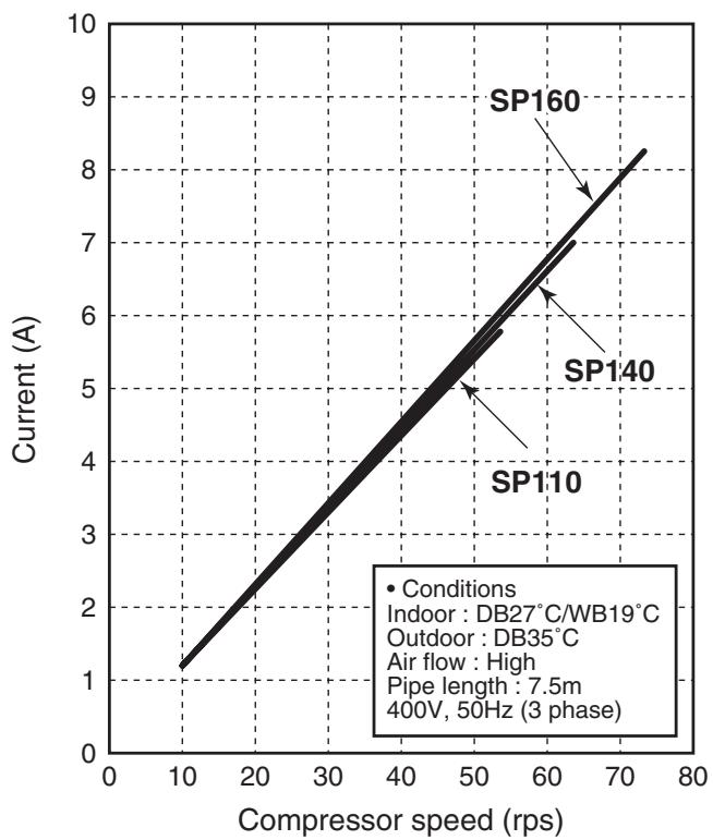
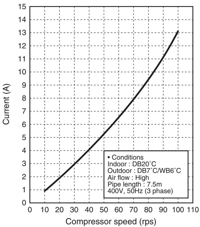
Operation characteristic curve, 60Hz
RAV-SP1104AT7 (Z) (ZG)
RAV-SP1404AT7 (Z) (ZG)
RAV-SP1604AT7 (Z) (ZG)
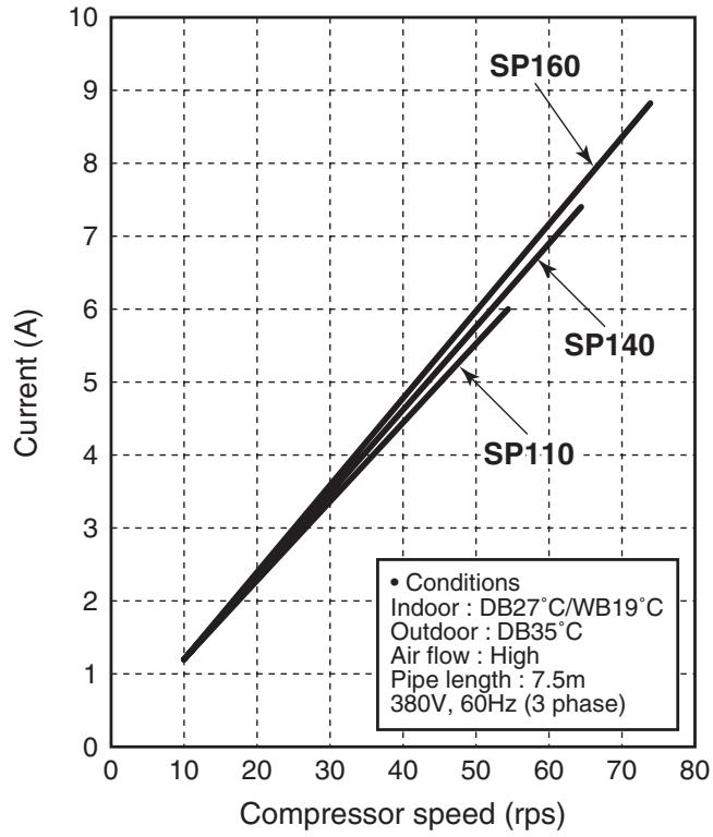
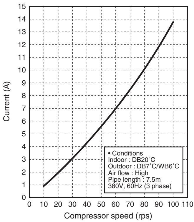
- Capacity variation ratio according to temperature
RAV-SP1104AT8 (Z) (ZG)-E, -TR
RAV-SP1404AT8 (Z) (ZG)-E, -TR
RAV-SP1604AT8 (Z) (ZG)-E, -TR
RAV-SP1104AT7 (Z) (ZG)
RAV-SP1404AT7 (Z) (ZG)
RAV-SP1604AT7 (Z) (ZG)
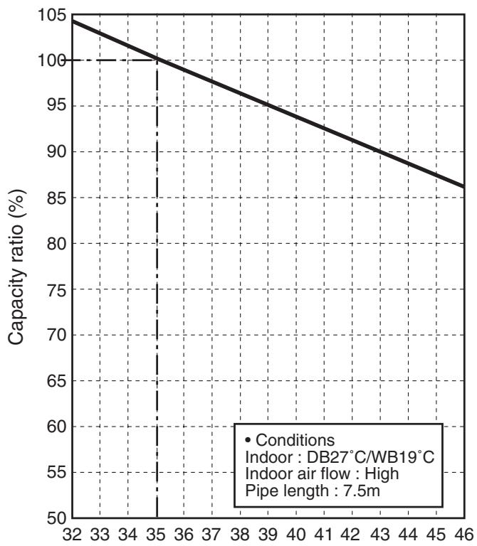
Outdoor temp. (^)
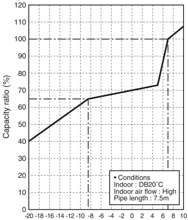
Outdoor temp. (^)
2. CONSTRUCTION VIEWS (EXTERNAL VIEWS)
2-1. Outdoor Unit
RAV-SP1104AT8 (Z) (ZG)-E, -TR, RAV-SP1404AT8 (Z) (ZG)-E, -TR, RAV-SP1604AT8 (Z) (ZG)-E, -TR
RAV-SP1104AT7 (Z) (ZG), RAV-SP1404AT7 (Z) (ZG), RAV-SP1604AT7 (Z) (ZG)
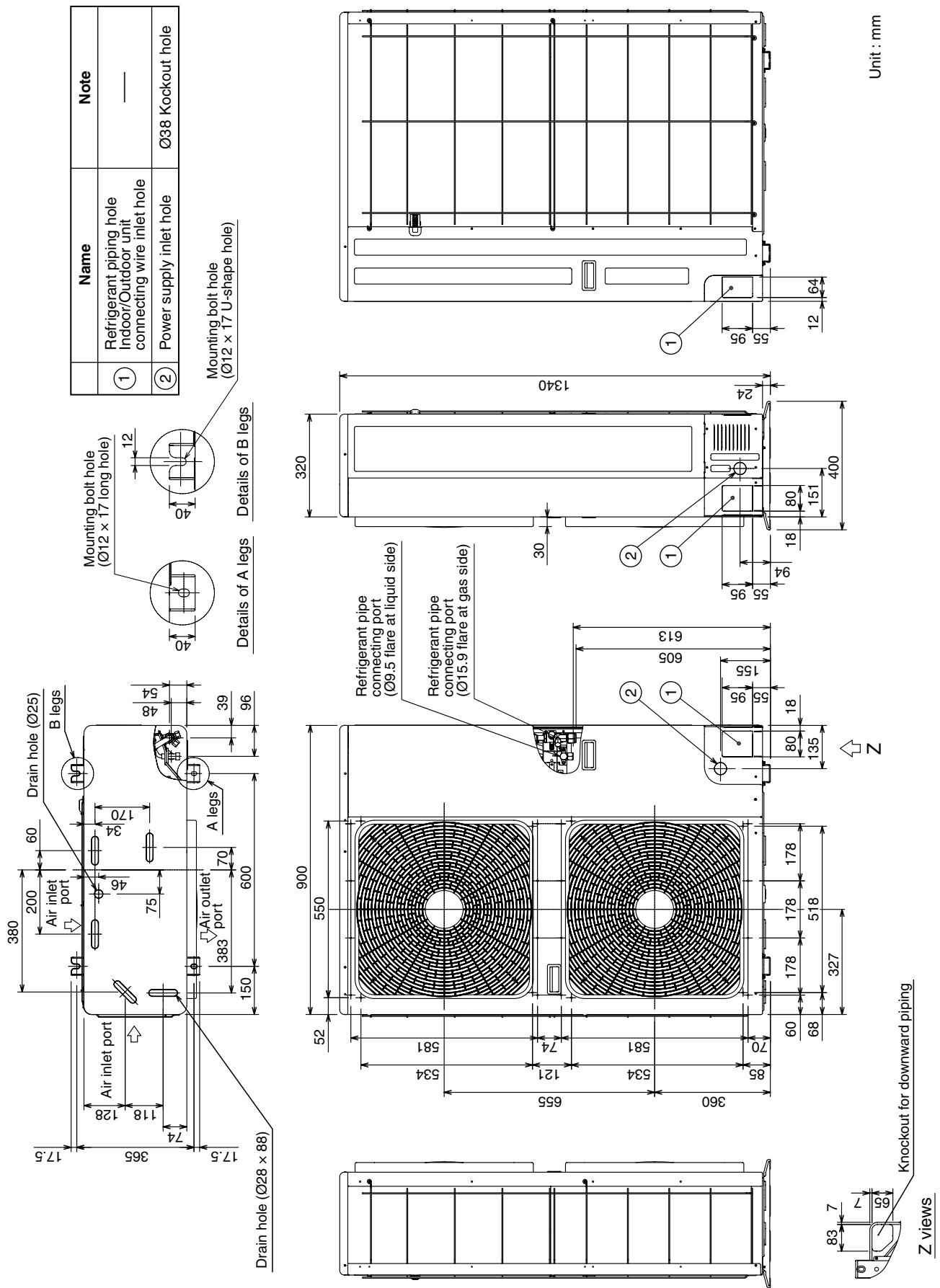
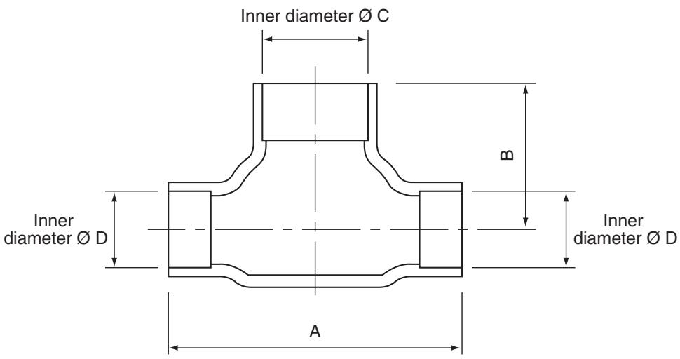
| Model (RBC-) | A | B | C | D | |
| TWP30E2 | Liquid side | 36 | 14 | Ø9.5 | Ø6.4 |
| Gas side | 43 | 23 | Ø15.9 | Ø12.7 | |
| TWP50E2 | Liquid side | 34 | 14 | Ø9.5 | Ø9.5 |
| Gas side | 44 | 21 | Ø15.9 | Ø15.9 | |
RBC-TRP100E (Simultaneous Triple)
Header assembly
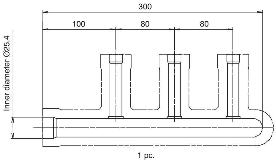
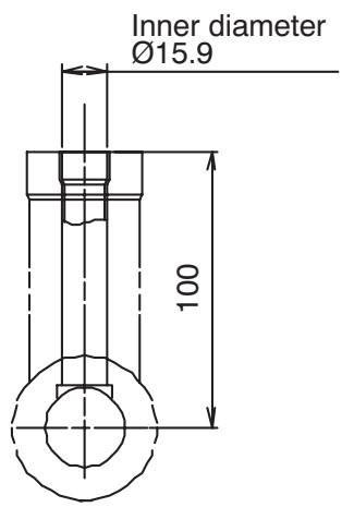
Branch pipe assembly
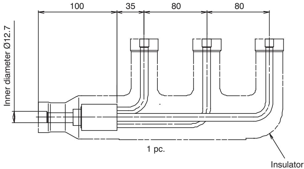
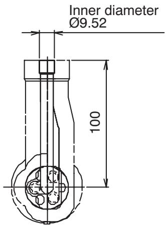
Gas side socket
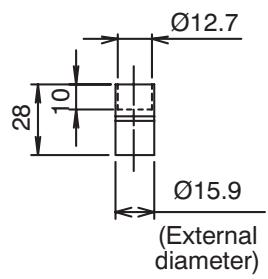
3 pcs.
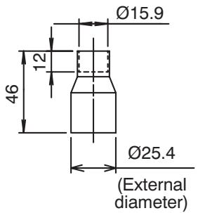
1 pc.
Liquid side socket
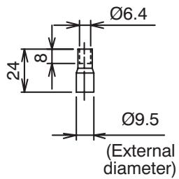
3 pcs.
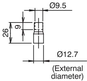
1 pc.
3. OUTDOOR UNIT REFRIGERATING CYCLE DIAGRAM
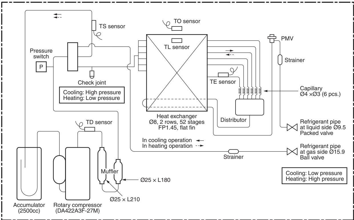
RAV-SP110 type
| Pressure | Pipe surface temperature (°C) | Compressor drive revolution frequency (rps) | Indoor fan | Indoor/Outdoor temp. conditions (DB/WB) (°C) | |||||||||
| (MPa) | (kg/cm2g) | Discharge | Suction | Indoor heat exchanger | Outdoor heat exchanger | ||||||||
| Pd | Ps | Pd | Ps | (TD) | (TS) | (TC) | (TL) | (TE) | Indoor | Outdoor | |||
| Cooling | Standard | 2.59 | 0.98 | 26.4 | 10.0 | 66 | 13 | 13 | 44 | 42 | 40 | HIGH | 27/19 |
| Overload | 3.30 | 1.09 | 33.7 | 11.1 | 78 | 9 | 13 | 49 | 43 | 53 | HIGH | 32/24 | |
| Low load | 1.74 | 0.75 | 17.8 | 7.7 | 46 | 7 | 5 | 32 | 25 | 21 | LOW | 18/15.5 | |
| Heating | Standard | 2.35 | 0.71 | 24.0 | 7.2 | 65 | 3 | 39 | 7 | 3 | 43 | HIGH | 20/- |
| Overload | 3.22 | 1.17 | 32.9 | 11.9 | 73 | 19 | 54 | 14 | 15 | 26 | LOW | 30/- | |
| Low load | 2.55 | 0.20 | 26.0 | 2.0 | 99 | -23 | 45 | -19 | -19 | 96 | HIGH | 15/- | |
RAV-SP140 type
| Pressure | Pipe surface temperature (°C) | Compressor drive revolution frequency (rps) | Indoor fan | Indoor/Outdoor temp. conditions (DB/WB) (°C) | |||||||||
| (MPa) | (kg/cm2g) | Discharge | Suction | Indoor heat exchanger | Outdoor heat exchanger | ||||||||
| Pd | Ps | Pd | Ps | (TD) | (TS) | (TC) | (TL) | (TE) | Indoor | Outdoor | |||
| Cooling | Standard | 2.77 | 0.87 | 28.3 | 8.9 | 74 | 12 | 10 | 46 | 42 | 54 | HIGH | 27/19 |
| Overload | 3.50 | 0.98 | 35.7 | 10.0 | 84 | 10 | 14 | 54 | 46 | 64 | HIGH | 32/24 | |
| Low load | 1.75 | 0.76 | 17.9 | 7.8 | 47 | 8 | 6 | 33 | 25 | 21 | LOW | 18/15.5 | |
| Heating | Standard | 2.66 | 0.67 | 27.1 | 6.8 | 75 | 2 | 44 | 7 | 3 | 55 | HIGH | 20/- |
| Overload | 3.13 | 1.05 | 31.9 | 10.7 | 72 | 16 | 53 | 12 | 13 | 26 | LOW | 30/- | |
| Low load | 2.48 | 0.20 | 25.3 | 2.0 | 98 | -23 | 44 | -19 | -19 | 96 | HIGH | 15/- | |
RAV-SP160 type
| Pressure | Pipe surface temperature (°C) | Compressor drive revolution frequency (rps) | Indoor fan | Indoor/Outdoor temp. conditions (DB/WB) (°C) | |||||||||
| (MPa) | (kg/cm2g) | Discharge | Suction | Indoor heat exchanger | Outdoor heat exchanger | ||||||||
| Pd | Ps | Pd | Ps | (TD) | (TS) | (TC) | (TL) | (TE) | Indoor | Outdoor | |||
| Cooling | Standard | 2.89 | 0.78 | 29.5 | 8.0 | 81 | 10 | 9 | 48 | 43 | 65 | HIGH | 27/19 |
| Overload | 3.61 | 0.90 | 36.8 | 9.2 | 88 | 11 | 15 | 57 | 49 | 74 | HIGH | 32/24 | |
| Low load | 1.75 | 0.77 | 17.9 | 7.9 | 48 | 9 | 7 | 33 | 26 | 21 | LOW | 18/15.5 | |
| Heating | Standard | 2.88 | 0.65 | 29.4 | 6.6 | 82 | 2 | 47 | 7 | 3 | 63 | HIGH | 20/- |
| Overload | 3.04 | 1.05 | 31.0 | 10.7 | 71 | 16 | 52 | 12 | 13 | 26 | LOW | 30/- | |
| Low load | 2.48 | 0.20 | 25.3 | 2.0 | 98 | -23 | 44 | -19 | -19 | 96 | HIGH | 15/- | |
- This compressor has 4-pole motor. The value when compressor frequency (Hz) is measured by a clamp meter becomes 2 times of No. of compressor revolutions (rps).
4. WIRING DIAGRAM
4-1. Outdoor Unit
RAV-SP1104AT8 (Z) (ZG)-E, -TR, RAV-SP1404AT8 (Z) (ZG)-E, -TR, RAV-SP1604AT8 (Z) (ZG)-E, -TR
RAV-SP1104AT7 (Z) (ZG), RAV-SP1404AT7 (Z) (ZG), RAV-SP1604AT7 (Z) (ZG)
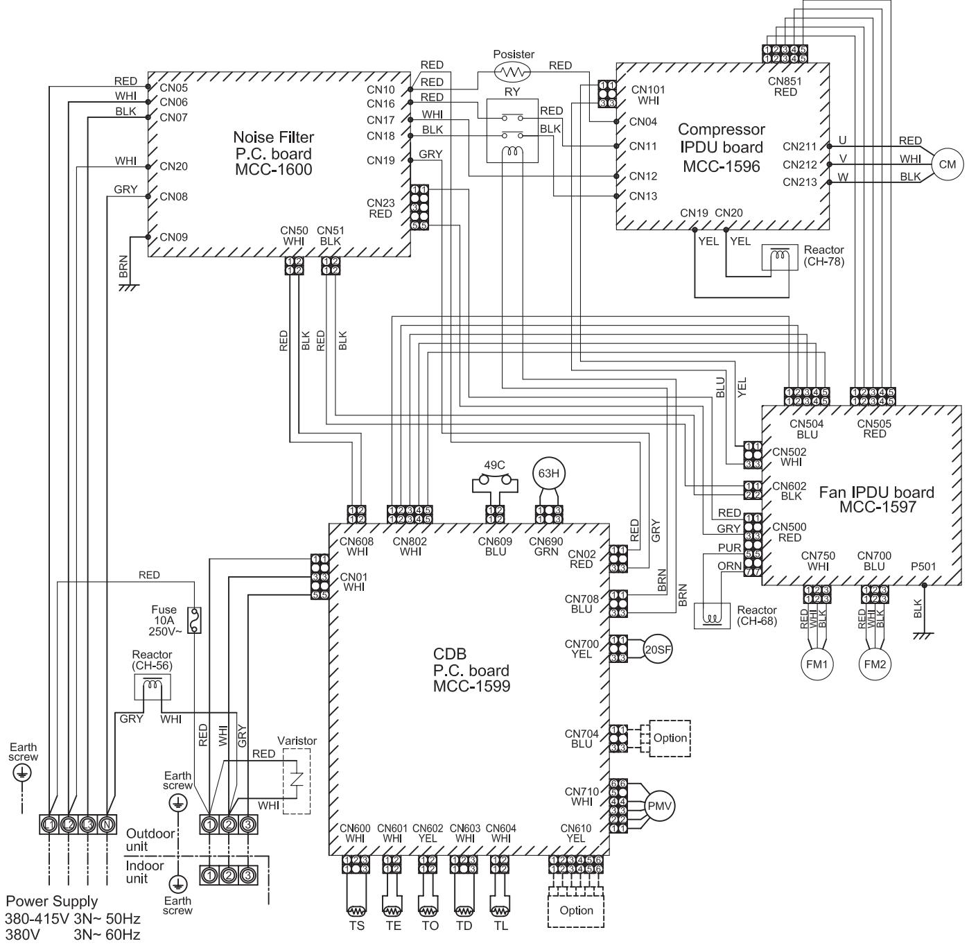
| Symbol | Part name |
| CM | Compressor |
| FM1,2 | Fan motor |
| PMV | Pulse motor valve |
| TD | Pipe temperature sensor (Discharge) |
| TS | Pipe temperature sensor (Suction) |
| TE | Heat exchanger sensor 1 |
| TL | Heat exchanger sensor 2 |
| TO | Outside temperature sensor |
| 20SF | 4-way valve coil |
| 49C | Compressor case thermostat |
| 63H | High-pressure switch |
| RY | Relay |
| Color Identification | |
| BLK : BLACK | WHI : WHITE |
| BLU : BLUE | BRN : BROWN |
| RED : RED | ORN : ORANGE |
| GRY : GRAY | YEL : YELLOW |
| GRN : GREEN | PUR : PURPLE |
- indicates the terminal block. Alphanumeric characters in the cycle indicate the terminal No.
- The two-dot chain line indicates the wiring procured locally.
- indicates the P.C. board.
4.For the indoor unit circuit, refer to the wiring diagram of the indoor unit.
5. SPECIFICATIONS OF ELECTRICAL PARTS
5-1. Outdoor Unit
| No. | Parts name | Type | Specifications |
| 1 | Compressor | DA422A3F-27M | — |
| 2 | Outdoor fan motor | ICF-280-A100-1 | DC 280 V, 100 W |
| 3 | 4-way valve coil | STF-01AJ502E1 | AC 220 – 240 V, 50/60 Hz |
| 4 | PMV coil | UKV-A038 | DC 12 V |
| 5 | High pressure switch | ACB-4UB83W | OFF: 4.15 MPa |
| 6 | Reactor | CH-78 | 4.2 mH, 16 A |
| 7 | Reactor | CH-68 | 18 mH, 5 A |
| 8 | Reactor | CH-56 | 5.8 mH, 18.5 A |
| 9 | P.C. board (Compressor drive) | MCC-1596 | — |
| 10 | P.C. board (Fan motor drive) | MCC-1597 | — |
| 11 | P.C. board (Control) | MCC-1599 | — |
| 12 | P.C. board (Noise filter) | MCC-1600 | — |
| 13 | Outdoor temp. sensor (TO sensor) | — | 10 kΩ at 25°C |
| 14 | Discharge temp. sensor (TD sensor) | — | 50 kΩ at 25°C |
| 15 | Suction temp. sensor (TS sensor) | — | 10 kΩ at 25°C |
| 16 | Heat exchanger sensor (TE sensor) | — | 10 kΩ at 25°C |
| 17 | Heat exchanger mid. temp. sensor (TL sensor) | — | 50 kΩ at 25°C |
| 18 | Fuse | TLC 10A | 10 A, 250 V |
| 19 | Fuse (Mounted on P.C. board, MCC-1596) | GAC1 31.5A | 31.5 A, 500 V |
| 20 | Fuse (Mounted on P.C. board, MCC-1596) | SCT 3.15A | T3.15 A, AC 250 V |
| 21 | Fuse (Mounted on P.C. board, MCC-1597) | GDM 250V 15A | 15 A, 250 V |
| 22 | Fuse (Mounted on P.C. board, MCC-1597) | SCT 3.15A | T3.15 A, AC 250 V |
| 23 | Fuse (Mounted on P.C. board, MCC-1599) | FJL 250V 3.15A | T3.15 A, AC 250 V |
| 24 | Fuse (Mounted on P.C. board, MCC-1600) | ET 6.3A | T6.3 A, AC 250 V |
| 25 | Relay | EL200/240A2-F(M) | Contact : AC 480 V, 20A |
| 26 | Posistor | ZPROYCE 101A 500 | 100 Ω, 500 V |
| 27 | Compressor thermo. | US-622 | OFF: 125 ± 4 °C, ON: 60 ± 5 °C |
6. REFRIGERANT R410A
This air conditioner adopts the new refrigerant HFC (R410A) which does not damage the ozone layer.
The working pressure of the new refrigerant R410A is 1.6 times higher than conventional refrigerant (R22). The refrigerating oil is also changed in accordance with change of refrigerant, so be careful that water, dust, and existing refrigerant or refrigerating oil are not entered in the refrigerant cycle of the air conditioner using the new refrigerant during installation work or servicing time.
The next section describes the precautions for air conditioner using the new refrigerant.
Conforming to contents of the next section together with the general cautions included in this manual, perform the correct and safe work.
6-1. Safety During Installation/Servicing
As R410A's pressure is about 1.6 times higher than that of R22, improper installation/servicing may cause a serious trouble. By using tools and materials exclusive for R410A, it is necessary to carry out installation/servicing safely while taking the following precautions into consideration.
- Never use refrigerant other than R410A in an air conditioner which is designed to operate with R410A.
If other refrigerant than R410A is mixed, pressure in the refrigeration cycle becomes abnormally high, and it may cause personal injury, etc. by a rupture.
- Confirm the used refrigerant name, and use tools and materials exclusive for the refrigerant R410A.
The refrigerant name R410A is indicated on the visible place of the outdoor unit of the air conditioner using R410A as refrigerant.
To prevent mischarging, the diameter of the service port differs from that of R22.
-
If a refrigeration gas leakage occurs during installation/servicing, be sure to ventilate fully. If the refrigerant gas comes into contact with fire, a poisonous gas may occur.
-
When installing or removing an air conditioner, do not allow air or moisture to remain in the refrigeration cycle.
Otherwise, pressure in the refrigeration cycle may become abnormally high so that a rupture or personal injury may be caused.
- After completion of installation work, check to make sure that there is no refrigeration gas leakage.
If the refrigerant gas leaks into the room, coming into contact with fire in the fan-driven heater, space heater, etc., a poisonous gas may occur.
- When an air conditioning system charged with a large volume of refrigerant is installed in a small room, it is necessary to exercise care so that, even when refrigerant leaks, its concentration does not exceed the marginal level.
If the refrigerant gas leakage occurs and its concentration exceeds the marginal level, an oxygen starvation accident may result.
- Be sure to carry out installation or removal according to the installation manual.
Improper installation may cause refrigeration trouble, water leakage, electric shock, fire, etc.
- Unauthorized modifications to the air conditioner may be dangerous. If a breakdown occurs please call a qualified air conditioner technician or electrician.
Improper repair may result in water leakage, electric shock and fire, etc.
6-2. Refrigerant Piping Installation
6-2-1. Piping Materials and Joints Used
For the refrigerant piping installation, copper pipes and joints are mainly used.
Copper pipes and joints suitable for the refrigerant must be chosen and installed.
Furthermore, it is necessary to use clean copper pipes and joints whose interior surfaces are less affected by contaminants.
1. Copper Pipes
It is necessary to use seamless copper pipes which are made of either copper or copper alloy and it is desirable that the amount of residual oil is less than 40mg / 10m
Do not use copper pipes having a collapsed, deformed or discolored portion (especially on the interior surface).
Otherwise, the expansion valve or capillary tube may become blocked with contaminants.
As an air conditioner using R410A incurs pressure higher than when using R22, it is necessary to choose adequate materials.
Thickities of copper pipes used with R410A are as shown in Table 6-2-1. Never use copper pipes thinner than 0.8mm even when it is available on the market.
NOTE
Refer to the "6-6. Instructions for Re-use Piping of R22 or R407C".
Table 6-2-1 Thicknesses of annealed copper pipes
| Thickness (mm) | |||
| Nominal diameter | Outer diameter (mm) | R410A | R22 |
| 1/4 | 6.4 | 0.80 | 0.80 |
| 3/8 | 9.5 | 0.80 | 0.80 |
| 1/2 | 12.7 | 0.80 | 0.80 |
| 5/8 | 15.9 | 1.00 | 1.00 |
1. Joints
For copper pipes, flare joints or socket joints are used. Prior to use, be sure to remove all contaminants.
a) Flare Joints
Flare joints used to connect the copper pipes cannot be used for pipings whose outer diameter exceeds 20mm . In such a case, socket joints can be used.
Sizes of flare pipe ends, flare joint ends and flare nuts are as shown in Tables 6-2-3 to 6-2-5 below.
b) Socket Joints
Socket joints are such that they are brazed for connections, and used mainly for thick pipings whose diameter is larger than 20~mm . Thicknesses of socket joints are as shown in Table 6-2-2.
Table 6-2-2 Minimum thicknesses of socket joints
| Nominal diameter | Reference outer diameter of copper pipe jointed (mm) | Minimum joint thickness (mm) |
| 1/4 | 6.4 | 0.50 |
| 3/8 | 9.5 | 0.60 |
| 1/2 | 12.7 | 0.70 |
| 5/8 | 15.9 | 0.80 |
6-2-2. Processing of Piping Materials
When performing the refrigerant piping installation, care should be taken to ensure that water or dust does not enter the pipe interior, that no other oil other than lubricating oils used in the installed air conditioner is used, and that refrigerant does not leak.
When using lubricating oils in the piping processing, use such lubricating oils whose water content has been removed. When stored, be sure to seal the container with an airtight cap or any other cover.
1. Flare Processing Procedures and Precautions
a) Cutting the Pipe
By means of a pipe cutter, slowly cut the pipe so that it is not deformed.
b) Removing Burrs and Chips
If the flared section has chips or burrs, refrigerant leakage may occur.
Carefully remove all burrs and clean the cut surface before installation.
c) Insertion of Flare Nut
d) Flare Processing
Make certain that a clamp bar and copper pipe have been cleaned.
By means of the clamp bar, perform the flare processing correctly.
Use either a flare tool for R410A or conventional flare tool.
Flare processing dimensions differ according to the type of flare tool.
When using a conventional flare tool, be sure to secure "dimension A" by using a gauge for size adjustment.
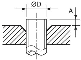
Fig. 6-2-1 Flare processing dimensions
Table 6-2-3 Dimensions related to flare processing for R410A / R22
| Nominal diameter | Outer diameter (mm) | Thickness (mm) | A (mm) | ||||
| Flare tool for R410A, R22 clutch type | Conventional flare tool (R410A) | Conventional flare tool (R22) | |||||
| Clutch type | Wing nut type | Clutch type | Wing nut type | ||||
| 1/4 | 6.4 | 0.8 | 0 to 0.5 | 1.0 to 1.5 | 1.5 to 2.0 | 0.5 to 1.0 | 1.0 to 1.5 |
| 3/8 | 9.5 | 0.8 | 0 to 0.5 | 1.0 to 1.5 | 1.5 to 2.0 | 0.5 to 1.0 | 1.0 to 1.5 |
| 1/2 | 12.7 | 0.8 | 0 to 0.5 | 1.0 to 1.5 | 2.0 to 2.5 | 0.5 to 1.0 | 1.5 to 2.0 |
| 5/8 | 15.9 | 1.0 | 0 to 0.5 | 1.0 to 1.5 | 2.0 to 2.5 | 0.5 to 1.0 | 1.5 to 2.0 |
| 3/4 | 19.1 | 1.2 | 0 to 0.5 | 1.0 to 1.5 | 2.0 to 2.5 | — | — |
Table 6-2-4 Flare and flare nut dimensions for R410A
| Nominal diameter | Outer diameter (mm) | Thickness (mm) | Dimension (mm) | Flare nut width (mm) | |||
| A | B | C | D | ||||
| 1/4 | 6.4 | 0.8 | 9.1 | 9.2 | 6.5 | 13 | 17 |
| 3/8 | 9.5 | 0.8 | 13.2 | 13.5 | 9.7 | 20 | 22 |
| 1/2 | 12.7 | 0.8 | 16.6 | 16.0 | 12.9 | 23 | 26 |
| 5/8 | 15.9 | 1.0 | 19.7 | 19.0 | 16.0 | 25 | 29 |
| 3/4 | 19.1 | 1.2 | 24.0 | — | 19.2 | 28 | 36 |
Table 6-2-5 Flare and flare nut dimensions for R22
| Nominal diameter | Outer diameter (mm) | Thickness (mm) | Dimension (mm) | Flare nut width (mm) | |||
| A | B | C | D | ||||
| 1/4 | 6.4 | 0.8 | 9.1 | 9.2 | 6.5 | 13 | 17 |
| 3/8 | 9.5 | 0.8 | 13.0 | 13.5 | 9.7 | 20 | 22 |
| 1/2 | 12.7 | 0.8 | 16.2 | 16.0 | 12.9 | 20 | 24 |
| 5/8 | 15.9 | 1.0 | 19.4 | 19.0 | 16.0 | 23 | 27 |
| 3/4 | 19.1 | 1.0 | 23.3 | 24.0 | 19.2 | 34 | 36 |
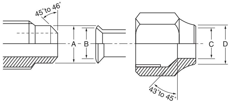
Fig. 6-2-2 Relations between flare nut and flare seal surface
2. Flare Connecting Procedures and Precautions
a) Make sure that the flare and union portions do not have any scar or dust, etc.
b) Correctly align the processed flare surface with the union axis.
c) Tighten the flare with designated torque by means of a torque wrench.
The tightening torque for R410A is the same as that for conventional R22.
Incidentally, when the torque is weak, the gas leakage may occur.
When it is strong, the flare nut may crack and may be made non-removable.
When choosing the tightening torque, comply with values designated by manufacturers.
Table 6-2-6 shows reference values.
NOTE
When applying oil to the flare surface, be sure to use oil designated by the manufacturer.
If any other oil is used, the lubricating oils may deteriorate and cause the compressor to burn out.
Table 6-2-6 Tightening torque of flare for R410A [Reference values]
| Nominal diameter | Outer diameter (mm) | Tightening torque N·m (kgf·m) | Tightening torque of torque wrenches available on the market N·m (kgf·m) |
| 1/4 | 6.4 | 14 to 18 (1.4 to 1.8) | 16 (1.6), 18 (1.8) |
| 3/8 | 9.5 | 33 to 42 (3.3 to 4.2) | 42 (4.2) |
| 1/2 | 12.7 | 50 to 62 (5.0 to 6.2) | 55 (5.5) |
| 5/8 | 15.9 | 63 to 77 (6.3 to 7.7) | 65 (6.5) |
| 3/4 | 19.1 | 100 to 120 (10.0 to 12.0) | — |
6-3. Tools
6-3-1. Required Tools
Refer to the "4. Tools"
6-4. Recharging of Refrigerant
When it is necessary to recharge refrigerant, charge the specified amount of new refrigerant according to the following steps.
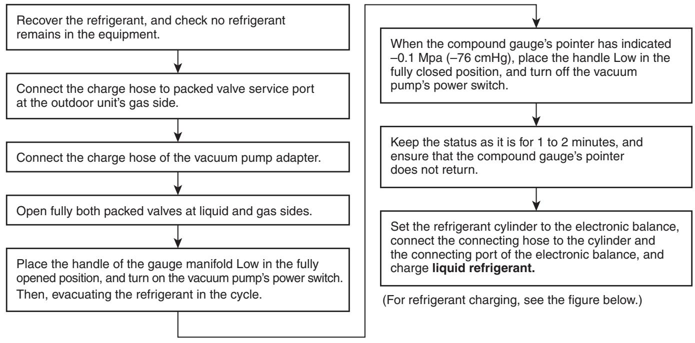
1) Never charge refrigerant exceeding the specified amount.
2) If the specified amount of refrigerant cannot be charged, charge refrigerant bit by bit in COOL mode.
3) Do not carry out additional charging.
When additional charging is carried out if refrigerant leaks, the refrigerant composition changes in the refrigeration cycle, that is characteristics of the air conditioner changes, refrigerant exceeding the specified amount is charged, and working pressure in the refrigeration cycle becomes abnormally high pressure, and may cause a rupture or personal injury.
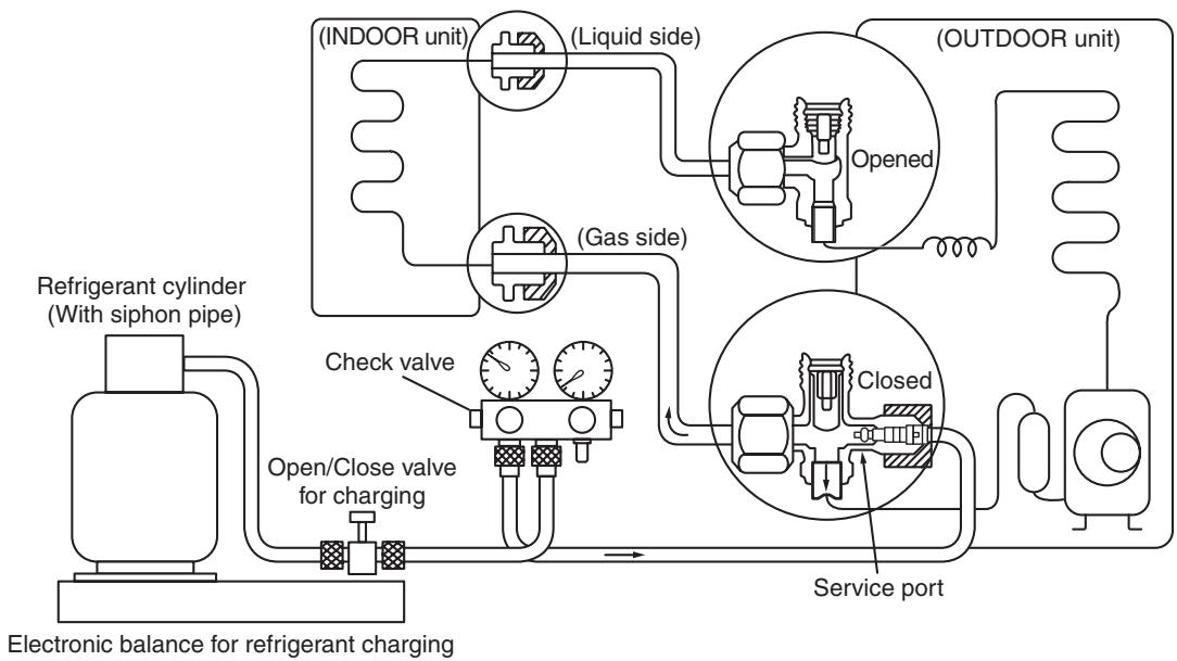
Fig. 6-4-1 Configuration of refrigerant charging
1) Be sure to make setting so that liquid can be charged.
2) When using a cylinder equipped with a siphon, liquid can be charged without turning it upside down.
It is necessary for charging refrigerant under condition of liquid because R410A is mixed type of refrigerant.
Accordingly, when charging refrigerant from the refrigerant cylinder to the equipment, charge it turning the cylinder upside down if cylinder is not equipped with siphon.
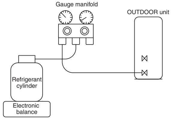
[ Cylinder with siphon ]
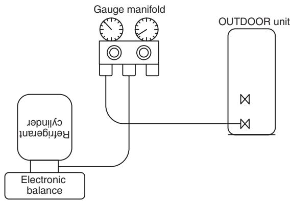
[ Cylinder without siphon ]
R410A refrigerant is HFC mixed refrigerant.
Therefore, if it is charged with gas, the composition of the charged refrigerant changes and the characteristics of the equipment varies.
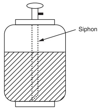
Fig. 6-4-2
6-5. Brazing of Pipes
6-5-1. Materials for Brazing
1. Silver brazing filler
Silver brazing filler is an alloy mainly composed of silver and copper.
It is used to join iron, copper or copper alloy, and is relatively expensive though it excels in solderability.
2. Phosphor bronze brazing filler
Phosphor bronze brazing filler is generally used to join copper or copper alloy.
3. Low temperature brazing filler
Low temperature brazing filler is generally called solder, and is an alloy of tin and lead.
Since it is weak in adhesive strength, do not use it for refrigerant pipes.
1) Phosphor bronze brazing filler tends to react with sulfur and produce a fragile compound water solution, which may cause a gas leakage. Therefore, use any other type of brazing filler at a hot spring resort, etc., and coat the surface with a paint.
2) When performing brazing again at time of servicing, use the same type of brazing filler.
6-5-2. Flux
1. Reason why flux is necessary
- By removing the oxide film and any foreign matter on the metal surface, it assists the flow of brazing filler.
- In the brazing process, it prevents the metal surface from being oxidized.
- By reducing the brazing filler's surface tension, the brazing filler adheres better to the treated metal.
2. Characteristics required for flux
- Activated temperature of flux coincides with the brazing temperature.
- Due to a wide effective temperature range, flux is hard to carbonize.
- It is easy to remove slag after brazing.
- The corrosive action to the treated metal and brazing filler is minimum.
- It excels in coating performance and is harmless to the human body.
As the flux works in a complicated manner as described above, it is necessary to select an adequate type of flux according to the type and shape of treated metal, type of brazing filler and brazing method, etc.
3. Types of flux
Noncorrosive flux
Generally, it is a compound of borax and boric acid.
It is effective in case where the brazing temperature is higher than 800^ .
- Activated flux
Most of fluxes generally used for silver brazing are this type.
It features an increased oxide film removing capability due to the addition of compounds such as potassium fluoride, potassium chloride and sodium fluoride to the borax-boric acid compound.
4. Piping materials for brazing and used brazing filler/flux
| Piping material | Used brazing filler | Used flux |
| Copper - Copper | Phosphor copper | Do not use |
| Copper - Iron | Silver | Paste flux |
| Iron - Iron | Silver | Vapor flux |
1) Do not enter flux into the refrigeration cycle.
2) When chlorine contained in the flux remains within the pipe, the lubricating oil deteriorates. Therefore, use a flux which does not contain chlorine.
3) When adding water to the flux, use water which does not contain chlorine (e.g. distilled water or ion-exchange water).
4) Remove the flux after brazing.
6-5-3. Brazing
As brazing work requires sophisticated techniques, experiences based upon a theoretical knowledge, it must be performed by a person qualified.
In order to prevent the oxide film from occurring in the pipe interior during brazing, it is effective to proceed with brazing while letting dry Nitrogen gas flow.
Never use gas other than Nitrogen gas.
1. Brazing method to prevent oxidation
1) Attach a reducing valve and a flow-meter to the Nitrogen gas cylinder.
2) Use a copper pipe to direct the piping material, and attach a flow-meter to the cylinder.
3) Apply a seal onto the clearance between the piping material and inserted copper pipe for Nitrogen in order to prevent backflow of the Nitrogen gas.
4) When the Nitrogen gas is flowing, be sure to keep the piping end open.
5) Adjust the flow rate of Nitrogen gas so that it is lower than 0.05 m^3/Hr or 0.02 MPa (0.2 kgf/cm^2) by means of the reducing valve.
6) After performing the steps above, keep the Nitrogen gas flowing until the pipe cools down to a certain extent (temperature at which pipes are touchable with hands).
7) Remove the flux completely after brazing.
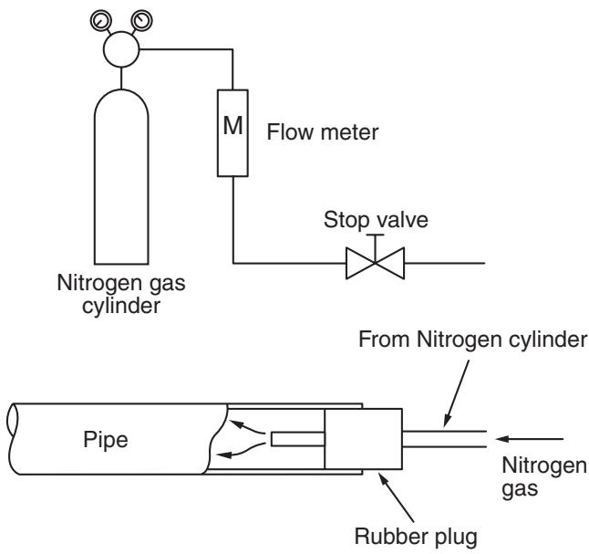
Fig. 6-5-1 Prevention of oxidation during brazing
6-6. Instructions for Re-use Piping of R22 or R407C
Instruction of Works:
The existing R22 and R407C piping can be reused for our digital inverter R410A products installations.
NOTE)
Confirmation of existence of scratch or dent of the former pipes to be applied and also confirmation of reliability of the pipe strength are conventionally referred to the local site.
If the definite conditions can be cleared, it is possible to update the existing R22 and R407C pipes to those for R410A models.
6-6-1. Basic Conditions Needed to Reuse the Existing Pipe
Check and observe three conditions of the refrigerant piping works.
- Dry (There is no moisture inside of the pipes.)
- Clean (There is no dust inside of the pipes.)
- Tight (There is no refrigerant leak.)
6-6-2. Restricted Items to Use the Existing Pipes
In the following cases, the existing pipes cannot be reused as they are. Clean the existing pipes or exchange them with new pipes.
- When a scratch or dent is heavy, be sure to use the new pipes for the works.
-
When the thickness of the existing pipe is thinner than the specified "Pipe diameter and thickness" be sure to use the new pipes for the works.
-
The operating pressure of R410A is high (1.6 times of R22 and R407C). If there is a scratch or dent on the pipe or thinner pipe is used, the pressure strength is poor and may cause breakage of the pipe at the worst.
-
Pipe diameter and thickness (mm)
| Pipe outer diameter | Ø6.4 | Ø9.5 | Ø12.7 | Ø15.9 | Ø19.0 | |
| Thickness | R410A | 0.8 | 0.8 | 0.8 | 1.0 | 1.0 |
| R22 (R407C) | ||||||
-
In case that the pipe diameter is 0.12.7 ~mm or less and the thickness is less than 0.7 ~mm , be sure to use the new pipes for works.
-
The pipes are left as coming out or gas leaks. (Poor refrigerant)
- There is possibility that rain water or air including moisture enters in the pipe.
- Refrigerant recovery is impossible. (Refrigerant recovery by the pump-down operation on the existing air conditioner)
- There is possibility that a large quantity of poor oil or moisture remains inside of the pipe.
- A dryer on the market is attached to the existing pipes.
-
There is possibility that copper green rust generated.
-
Check the oil when the existing air conditioner was removed after refrigerant had been recovered. In this case, if the oil is judged as clearly different compared with normal oil
-
The refrigerator oil is copper rust green : There is possibility that moisture is mixed with the oil and rust generates inside of the pipe.
- There is discolored oil, a large quantity of the remains, or bad smell.
-
A large quantity of sparkle remained wear-out powder is observed in the refrigerator oil.
-
The air conditioner which compressor was exchanged due to a faulty compressor. When the discolored oil, a large quantity of the remains, mixture of foreign matter, or a large quantity of sparkle remained wear-out powder is observed, the cause of trouble will occur.
- Installation and removal of the air conditioner are repeated with temporary installation by lease and etc.
-
In case that type of the refrigerator oil of the existing air conditioner is other than the following oil (Mineral oil), Suniso, Freol-S, MS (Synthetic oil), alkyl benzene (HAB, Barrel-freeze), ester series, PVE only of ether series.
-
Winding-insulation of the compressor may become inferior.
NOTE)
The above descriptions are results of confirmation by our company and they are views on our air conditioners, but they do not guarantee the use of the existing pipes of the air conditioner that adopted R410A in other companies.
6-6-3. Branching Pipe for Simultaneous Operation System
- In the concurrent twin system, when TOSHIBA-specified branching pipe is used, it can be reused. Branching pipe model name: RBC-TWP30E2, RBC-TWP50E2, RBC-TRP100E. On the existing air conditioner for simultaneous operation system (twin system), there is a case of using branch pipe that has insufficient compressive strength. In this case please change it to the branch pipe for R410A.
6-6-4. Curing of Pipes
When removing and opening the indoor unit or outdoor unit for a long time, cure the pipes as follows:
- Otherwise rust may generate when moisture or foreign matter due to dewing enters in the pipes.
- The rust cannot be removed by cleaning, and a new piping work is necessary.
| Place position | Term | Curing manner |
| Outdoors | 1 month or more | Pinching |
| Less than 1 month | Pinching or taping | |
| Indoors | Every time |
6-6-5. Final Installation Checks
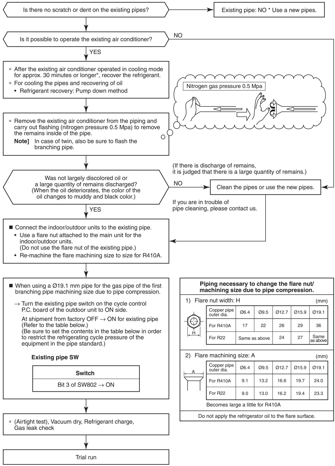
6-6-6. Handling of Existing Pipe
When using the existing pipe, carefully check it for the following:
- Wall thickness (within the specified range)
- Scratches and dents
Water, oil, dirt, or dust in the pipe - Flare looseness and leakage from welds
- Deterioration of copper pipe and heat insulator
Cautions for using existing pipe
- Do not reuse the flare to prevent gas leak.
Replace it with the supplied flare nut and then process it to a flare. - Blow nitrogen gas or use an appropriate means to keep the inside of the pipe clean.
If discolored oil or much residue is discharged, wash the pipe. - Check welds, if any, on the pipe for gas leak.
When the pipe corresponds to any of the following, do not use it. Install a new pipe instead. - The pipe has been open (disconnected from indoor unit or outdoor unit) for a long period.
- The pipe has been connected to an outdoor unit that does not use refrigerant R22, R410A or R407C.
- The existing pipe must have a wall thickness equal to or larger than the following thickness.
| Reference outside diameter (mm) | Wall thickness (mm) |
| Ø9.5 | 0.8 |
| Ø15.9 | 1.0 |
| Ø19.1 | 1.0 |
- Never use any pipe with a wall thickness less than these thicknesses due to insufficient pressure capacity.
- To use an existing Ø19.1 mm pipe, set bit 3 of SW802 (switch for existing pipe) on the P.C. board of the outdoor unit to ON.
In this case, the heating performance may be reduced depending on the outside air temperature and room temperature.
| SW802 | |
| When shipped from factory | When using existing pipe |
| ON 1 2 3 4 | ON 1 2 3 4 |
6-6-7. Recovery Method of Refrigerant
- Use the refrigerant recovery switch SW801 on the P.C. board of the outdoor unit to recover refrigerant when the indoor unit or outdoor unit is moved.
Procedure
- Turn on the power of the air conditioner.
- Select the FAN mode for indoor unit operation with the remote controller.
- Set SW804 on the P.C. board of the outdoor unit to all OFF, and then push SW801 for one second or more.
The air conditioner enters the forced cooling mode for up to 10 minutes.
Operation or handling the valve to recover refrigerant during this time period.
- Upon completion of refrigerant recovery, close the valve and push SW801 for at least one second to stop operation.
- Turn off the power.
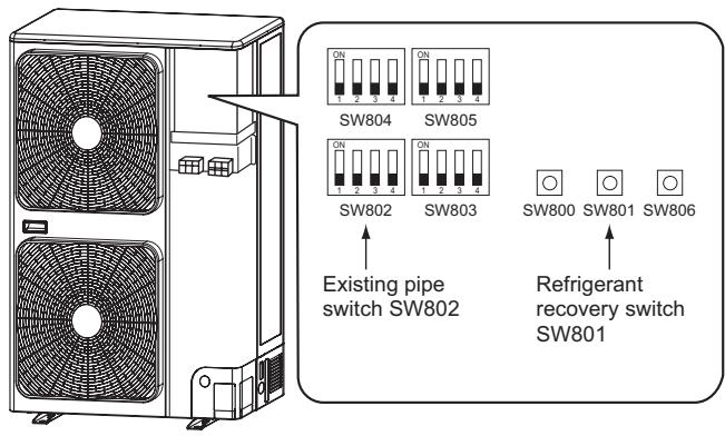

DANGER
Take care for an electric shock because the P.C. board is electrified.
7. CIRCUIT CONFIGURATION AND CONTROL SPECIFICATIONS
7-1. Outdoor Unit Control
7-1-1. Print Circuit Board, MCC-1596 (Compressor IPDU)
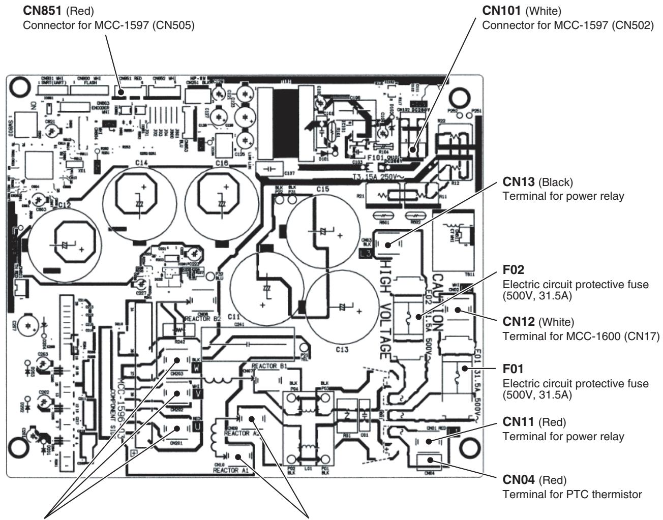
CN211 (Red), CN212 (White), CN213 (Black) Compressor output terminal
CN19 (Yellow), CN20 (Yellow) Terminal for reactor CH78
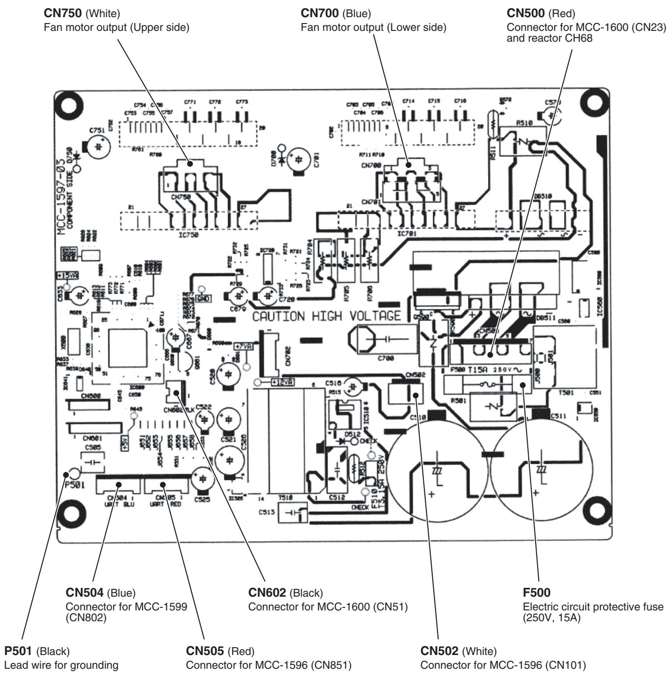
7-1-3. Print Circuit Board, MCC-1599 (Interface (CDB))
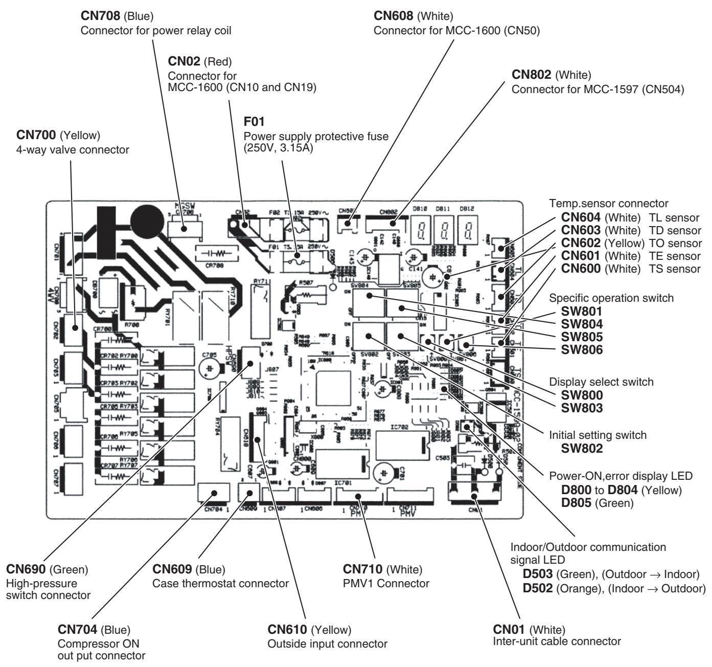
7-1-4. Print Circuit Board, MCC-1600 (Noise Filter)
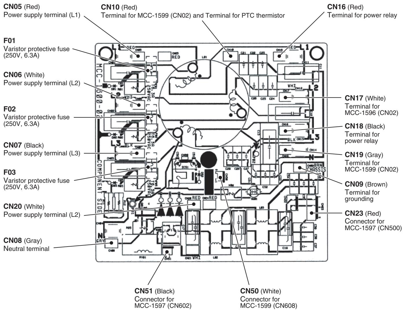
7-2. Outline of Main Controls
1. PMV (Pulse Motor Valve) control
1) PMV is controlled between 30 and 500 pulses during operation.
2) In cooling operation, PMV is usually controlled with the temperature difference between TS sensor and TC sensor aiming 1 to 4K as the target value.
3) In heating operation, PMV is usually controlled with the temperature difference between TS sensor and TE sensor aiming -1 to 4K as the target value.
4) When the cycle excessively heated in both cooling and heating operation, PMV is controlled by TD sensor. The target value is usually 91^ in cooling operation and 96^ in heating operation.
REQUIREMENT
A sensor trouble may cause a liquid back-flow or abnormal overheat resulting in excessive shortening of the compressor life. In a case of trouble on the compressor, be sure to check there is no error in the resistance value or the refrigerating cycle of each sensor after repair and then start the operation.
2. Discharge temperature release control
1) When the discharge temperature did not fall or the discharge temperature rapidly went up by PMV control, this control lowers the operation frequency. It subdivides the frequency control up to 0.6Hz to stabilize the cycle.
2) When the discharge temperature detected an abnormal stop zone, the compressor stops and then restarts after 2 minutes 30 seconds.
The error counting is cleared when the operation continued for 10 minutes. If the error is detected by 4 times without clearing, the error is determined and restarting is not performed.
- The cause is considered as excessively little amount of refrigerant, PMV error or clogging of the cycle.
3) For displayed contents of error, confirm on the check code list.
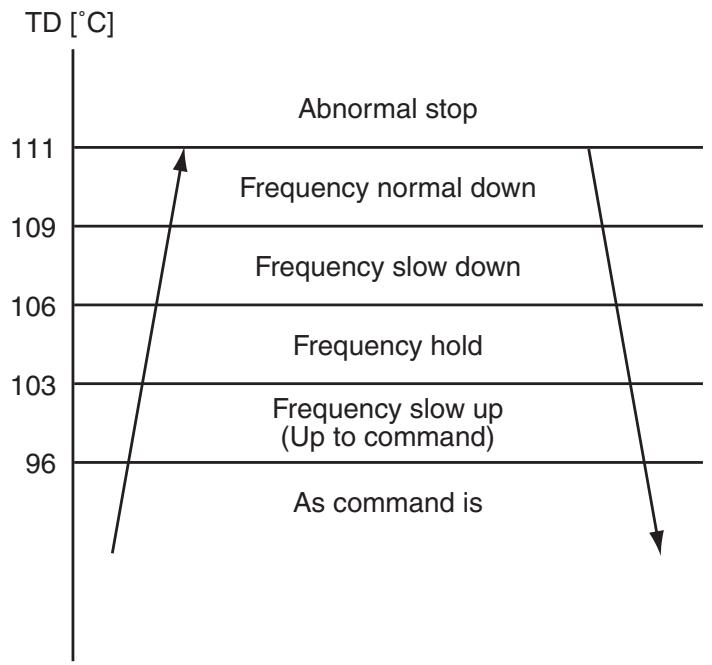
Revolution frequency allocation of fan taps [rpm]
| W1 | W2 | W3 | W4 | W5 | W6 | W7 | W8 | W9 | WA | WB | WC | WD | WE | ||
| SP110 to SP160 | Up | 200 | 240 | 240 | 260 | 320 | 380 | 480 | 500 | 530 | 610 | 640 | 660 | 720 | 780 |
| Down | — | — | 200 | 280 | 360 | 400 | 500 | 520 | 550 | 630 | 660 | 700 | 740 | 820 | |
① The outdoor fan is controlled by TL sensor, TO sensor and the operation frequency. The outdoor fan is controlled by every 1 tap of DC fan control (14 taps).
(2) Only for 60 seconds after the operation has started, the maximum fan tap corresponding to the zone in the following table is fixed and then the fan is controlled by temperature of TL sensor.
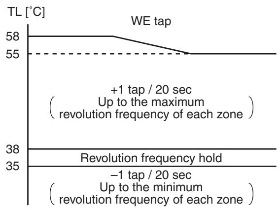
| Temp. range | 20 Hz or lower | 20Hz to 45Hz | 45Hz or higher | |||
| Min. | Max. | Min. | Max. | Min. | Max. | |
| 38°C ≤ TO | W6 | WC | W8 | WD | WA | WD |
| 29°C ≤ TO < 38°C | W5 | WB | W7 | WC* | W9 | WC |
| 15°C ≤ TO < 29°C | W4 | W8 | W6 | WA | W8 | WC |
| 5°C ≤ TO < 15°C | W3 | W6 | W5 | W8 | W7 | WA |
| 0°C ≤ TO < 5°C | W2 | W4 | W4 | W6 | W5 | W8 |
| -4°C ≤ TO < 0°C | W2 | W3 | W3 | W5 | W4 | W6 |
| TO < -4°C | W1 | W2 | W1 | W4 | W2 | W6 |
| TO error | W1 | WC | W1 | WD | W2 | WD |
*:WB for SP110
3-2) Heating fan control
(1) The outdoor fan is controlled by TE sensor, TO sensor and the operation frequency. (Control from minimum W1 to maximum (according to the following table))
② For 3 minutes after the operation has started, the maximum fan tap corresponding to the zone in the following table is fixed and then the fan is controlled by temperature of TE sensor.
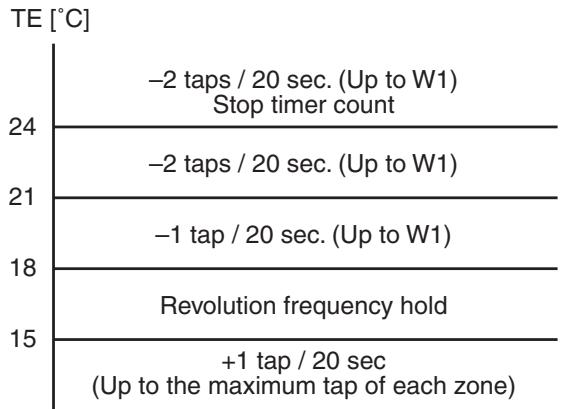
(3) When T E ≥ 24^ C continues for 5 minutes, the compressor stops.
It is the same status as the normal thermostat-OFF without error display.
The compressor restarts after approx. 2 minutes 30 seconds and this intermittent operation is not abnormal.
(4) In case that the status in item (3) generates frequently, stain on filter of the suction part of the indoor unit is considered.
Clean the filter and then restart the operation.
Object: SP140 (SP160)
| Temp. range | 20 Hz or lower | 20Hz to 45Hz | 45Hz or higher |
| Max. | Max. | Max. | |
| 10°C ≤ TO | W7 | W8 | W9 |
| 5°C ≤ TO < 10°C | W9 | WA | WB (WC) |
| -3°C ≤ TO < 5°C | WB (WC) | WB (WC) | WC |
| -10°C ≤ TO < -3°C | WC | WC | WC |
| TO < -10°C | WD | WD | WD |
| TO error | WD | WD | WD |
Object: SP110
| Temp. range | 20 Hz or lower | 20Hz to 45Hz | 45Hz or higher |
| Max. | Max. | Max. | |
| 10°C ≤ TO | W7 | W8 | W9 |
| 5°C ≤ TO < 10°C | W9 | WA | WA |
| -3°C ≤ TO < 5°C | WA | WA | WC |
| -10°C ≤ TO < -3°C | WC | WC | WC |
| TO < -10°C | WD | WD | WD |
| TO error | WD | WD | WD |
4. Coil heating control
1) This control function heats the compressor by turning on the stopped compressor instead of a case heater. It purposes to prevent stagnation of the refrigerant inside of the compressor.
2) As usual, turn on power of the compressor for the specified time before a test run after installation; otherwise a trouble of the compressor may be caused.
As same as a test run, it is recommended to turn on power of the compressor beforehand when starting operation after power of the compressor has been interrupted and left as it is for a long time.
3) A judgment for electricity is performed by TD and TO sensors.
If TO sensor is defective, a backup control is automatically performed by TE sensor.
For a case of defective TO sensor, judge it with outdoor LED display.
4) For every model, the power is turned off when TD is 30^ or more.
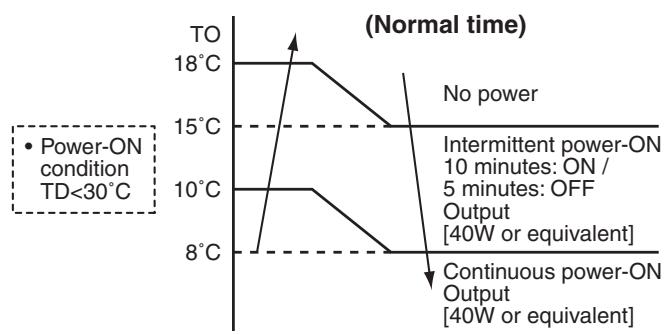
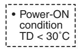
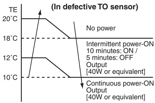
REQUIREMENT
While heating the coil, the power sound may be heard. However it is not a trouble.
5. Short intermittent operation preventive control
1) For 3 to 10 minutes after operation start, in some cases, the compressor does not stop to protect the compressor even if receiving the thermostat-OFF signal from indoor.
However it is not abnormal status. (The operation continuance differs according to the operation status.)
2) When the operation stops by the remote controller, the operation does not continue.
6. Current release control
No. of revolutions of the compressor is controlled by AC current value detected by T611 on the outdoor P.C. board so that the input current of the inverter does not exceed the specified value.
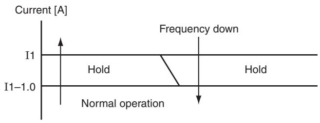
| Objective model | SP110 | SP140 | SP160 | |||
| COOL | HEAT | COOL | HEAT | COOL | HEAT | |
| I1 value [A] | 9.6 | 15.2 | 9.6 | 15.2 | 9.6 | 15.2 |
7. Current release value shift control
1) This control purposes to prevent troubles of the electronic parts such as the compressor driving elements and the compressor during cooling operation.
2) The current release control value (I1) is selected from the following table according to TO sensor value.
[A]
Current release control value (I1)
| Temperature range | SP110 | SP140 | SP160 |
| 47°C ≤ To | 7.5 | 7.5 | 7.5 |
| 39°C ≤ To < 47°C | 7.5 | 8.7 | 9.6 |
| To < 39°C | 9.6 | 9.6 | 9.6 |
| To < -5°C | 7.5 | 8.7 | 9.6 |
| TO error | 7.5 | 7.5 | 7.5 |
8. Over-current protective control
1) When the over-current protective circuit detected an abnormal current, stop the compressor.
2) The compressor restarts after 2 minutes 30 seconds setting [1] as an error count.
3) When the error count [8] was found, determine an error and restart operation is not performed.
4) For the error display contents, confirm on the check code list.
9. High-pressure release control
1) The operation frequency is controlled to restrain abnormal rising of high pressure by TL sensor in cooling operation and TC sensor in heating operation.
2) When TL sensor in cooling operation or TC sensor in heating operation detects abnormal temperature of the stop zone, stop the compressor and the error count becomes +1.
3) When the compressor stopped with 2), the operation restarts from the point of the normal operation zone (e point or lower) where it returned after 2 minutes 30 seconds.
4) The error count when the compressor stopped with 2) is cleared after the operation continued for 10 minutes. If the error count becomes [10] without clearing, the error is determined and reactivation is not performed.
5) For the error display contents, confirm on the check code list.
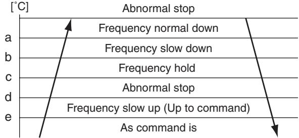
HEAT TC / COOL TL
| HEAT | COOL | |
| TC | TL | |
| a | 62°C | 63°C |
| b | 57°C | 62°C |
| c | 55°C | 60°C |
| d | 53°C | 58°C |
| e | 49°C | 54°C |
10. Defrost control
1) In heating operation, defrost operation is performed when TE sensor satisfies any condition in A zone to D zone.
2) During defrosting operation, it finishes if TE sensor continued 12^ or higher for 3 seconds or continued 7^ ≤ TE < 12^ for 1 minute.
The defrost operation also finishes when it continued for 10 minutes even if TE sensor temperature was 7^ or lower.
3) After defrost operation was reset, the compressor stopped for approx. 40 seconds and then the heating operation starts.
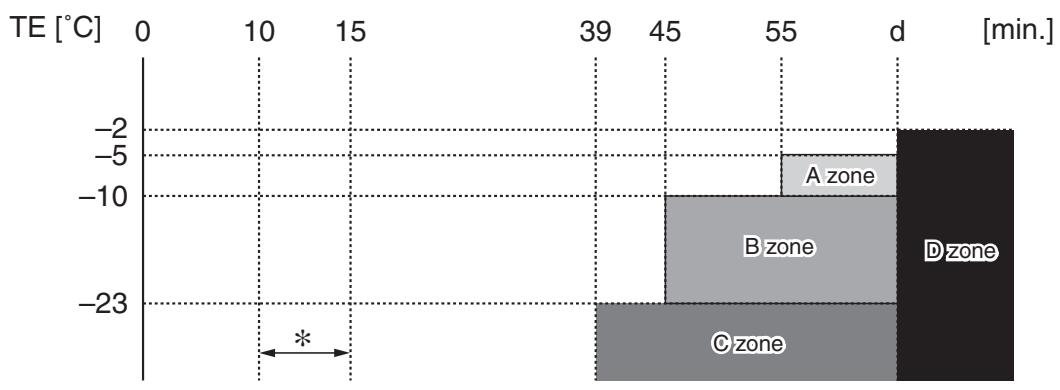
Start of heating operation
- The minimum TE value and To value between 10 and 15 minutes after heating operation has started are stored in memory as TEO and ToO, respectively.
| In normal To | In abnormal To | |
| A zone | When status (TEO- TE) - (ToO - To) ≥ 3°C continued for 20 seconds | When status (TEO - TE) ≥ 3°C continued for 20 seconds |
| B zone | When status (TEO - TE) - (ToO - To) ≥ 2°C continued for 20 seconds | When status (TEO - TE) ≥ 2°C continued for 20 seconds |
| C zone | When status (TE ≤ -23°C) continued for 20 seconds | |
| D zone | When compressor operation status of TE < -2°C is calculated by d portion | |
4) The time of above d can be changed by exchanging jumper [J805] with [J806] of the outdoor control P.C. board. (Setting at shipment: 150 minutes)
| J805 | J806 | d |
| ○ | ○ | 150 minutes Setting at shipment |
| ○ | × | 90 minutes |
| × | ○ | 60 minutes |
| × | × | 30 minutes |
:Short circuit, × :Open
11. High-pressure switch/Compressor case thermostat control
1) When the high-pressure switch or the compressor case thermostat operates, the operation of the compressor is terminated.
2) The compressor restarts after 5 minutes using [1] as an error count. After restart, the error count is cleared when operation continues for 10 minutes or more.
3) An error is confirmed with the error count [10].
4) For the indicated contents of error, confirm using the check code table.
8. TROUBLESHOOTING
8-1. Summary of Troubleshooting
< Wired remote controller type>
1. Before troubleshooting
1) Required tools/instruments
- and screwdrivers, spanners, radio cutting pliers, nippers, push pins for reset switch
- Tester, thermometer, pressure gauge, etc.
2) Confirmation points before check
a) The following operations are normal.
1. Compressor does not operate.
- Is not 3-minutes delay (3 minutes after compressor OFF)?
- Is not the outdoor unit in standby status though the remote controller reached the setup temperature?
- Does not timer operate during fan operation?
- Is not an overflow error detected on the indoor unit?
- Is not outside high-temperature operation controlled in heating operation?
2. Indoor fan does not rotate.
- Does not cool air discharge preventive control work in heating operation?
3. Outdoor fan does not rotate or air volume changes.
- Does not high-temperature release operation control work in heating operation?
- Does not outside low-temperature operation control work in cooling operation?
- Is not defrost operation performed?
4. ON/OFF operation cannot be performed from remote controller.
- Is not the control operation performed from outside/remote side?
- Is not automatic address being set up?
(When the power is turned on at the first time or when indoor unit address setting is changed, the operation cannot be performed for maximum approx. 5 minutes after power-ON.)
- Is not being carried out a test run by operation of the outdoor controller?
b) Did you return the cabling to the initial positions?
c) Are connecting cables of indoor unit and remote controller correct?
2. Troubleshooting procedure
When a trouble occurred, check the parts along with the following procedure.

NOTE
For cause of a trouble, power conditions or malfunction/erroneous diagnosis of microcomputer due to outer noise is considered except the items to be checked.
If there is any noise source, change the cables of the remote controller to shield cables.
1. Before troubleshooting
1) Required tools/instruments
- and screwdrivers, spanners, radio cutting pliers, nippers, etc.
- Tester, thermometer, pressure gauge, etc.
2) Confirmation points before check
a) The following operations are normal.
-
Compressor does not operate.
-
Is not 3-minutes delay (3 minutes after compressor OFF)?
- Is not the outdoor unit in standby status though the remote controller reached the setup temperature?
- Does not timer operate during fan operation?
- Is not an overflow error detected on the indoor unit?
-
Is not outside high-temperature operation controlled in heating operation?
-
Indoor fan does not rotate.
-
Does not cool air discharge preventive control work in heating operation?
3) Outdoor fan does not rotate or air volume changes.
- Does not high-temperature release operation control work in heating operation?
- Does not outside low-temperature operation control work in cooling operation?
- Is not defrost operation performed?
4) ON/OFF operation cannot be performed from remote controller.
- Is not forced operation performed?
- Is not the control operation performed from outside/remote side?
- Is not automatic address being set up?
- Is not being carried out a test run by operation of the outdoor controller?
a) Did you return the cabling to the initial positions?
b) Are connecting cables between indoor unit and receiving unit correct?
2. Troubleshooting procedure
(When the power is turned on at the first time or when indoor unit address setting is changed, the operation cannot be performed for maximum approx. 5 minutes after power-ON.)
When a trouble occurred, check the parts along with the following procedure.
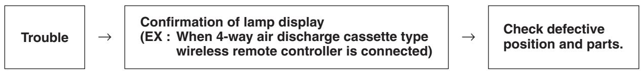
1) Outline of judgment
The primary judgment to check where a trouble occurred in indoor unit or outdoor unit is performed with the following method.
Method to judge the erroneous position by flashing indication on the display part of indoor unit (sensors of the receiving unit)
The indoor unit monitors operating status of the air conditioner, and the blocked contents of self-diagnosis are displayed restricted to the following cases if a protective circuit works.
8-2. Troubleshooting
8-2-1. Outline of judgment
The primary judgment to check whether a trouble occurred in the indoor unit or outdoor unit is carried out with the following method.
Method to judge the erroneous position by flashing indication on the display part of the indoor unit (sensors of the receiving part)
The indoor unit monitors the operating status of the air conditioner, and the blocked contents of self-diagnosis are displayed restricted to the following cases if a protective circuit works.

| Lamp indication | Check code | Cause of trouble occurrence |
| Operation Timer Ready ●●●No indication at all | — | Power supply OFF or miswiring between receiving unit and indoor unit |
| Operation Timer Ready ●●●Flash | E01 | Receiving error {Receiving unit Sending error} Miswiring or wire connection error between receiving unit and indoor unit |
| E02 | ||
| E03 | Communication stop | |
| E08 | Duplicated indoor unit No. Setup error | |
| E09 | Duplicated header units of remote controller | |
| E10 | Communication error between CPUs on indoor unit P.C. board | |
| E18 | Wire connection error between indoor units, Indoor power OFF (Communication stop between indoor master and follower or between main and sub indoor twin) | |
| Operation Timer Ready ●●●Flash | E04 | Miswiring between indoor unit and outdoor unit or connection errorr (Communication stop between indoor and outdoor units) |
| Operation Timer Ready ●●●Alternate flash | P01 | Overflow was detected. Protective device of indoor unit worked. |
| P10 | ||
| P12 | ||
| Operation Timer Ready ●●●Alternate flash | P03 | Outdoor unit discharge temp. error Protective device of *1 Outdoor high pressure system error outdoor unit worked. |
| P04 | ||
| P05 | Negative phase detection error Outdoor unit error | |
| P07 | ||
| P15 | ||
| P19 | 4-way valve system error (Indoor or outdoor unit judged.) | |
| P20 | Outdoor unit high pressure protection | |
| P22 | Outdoor unit: Outdoor unit error Protective device of *1 Outdoor unit: Inverter Idc operation outdoor unit worked. | |
| P26 | ||
| P29 | ||
| P31 | Stopped because of error of other indoor unit in a group (Check codes of E03/L03/L07/L08) |
*1: These are representative examples and the check code differs according to the outdoor unit to be combined.
| Lamp indication | Check code | Cause of trouble occurrence | |
| Operation Timer Ready | F01 | Heat exchanger sensor (TCJ) error | |
| F02 | Heat exchanger sensor (TC) error | ||
| P10 | Heat exchanger sensor (TA) error | ||
| Alternate flash | F04 | Discharge temp. sensor (TD) error | |
| F06 | Temp. sensor (TE) error | ||
| F07 | Temp. sensor (TL) error | ||
| F08 | Temp. sensor (TO) error | ||
| F12 | Temp. sensor (TS) error | ||
| F13 | Temp. sensor (TH) error | ||
| F15 | Temp. Sensor miswiring (TE, TS) | ||
| Operation Timer Ready | F29 | Indoor EEPROM error | |
| Simultaneous flash | |||
| Operation Timer Ready | F31 | Outdoor EEPROM error | |
| Simultaneous flash | |||
| Operation Timer Ready | H01 | Compressor break down\} Outdoor compressor system error *1 | |
| H02 | Compressor lock\} | ||
| H03 | Current detection circuit error\} Power supply, outdoor P.C. board error | ||
| H04 | Case thermostat worked.\} Compressor overheat, outdoor wiring error | ||
| H06 | PS pressure sensor error, low pressure protective operation\} Outdoor unit low pressure system error | ||
| Simultaneous flash | L03 | Duplicated header indoor units\}→AUTO address | |
| L07 | There is indoor unit of group connection in individual indoor unit.\* If group construction and address are not normal power supply turned on, automatically goes to address setup mode. | ||
| L08 | Unsetting of group address | ||
| L09 | Missed setting (Unset indoor capacity) | ||
| Operation Timer Ready | L10 | Unset model type (Service board) | |
| L20 | Duplicated indoor central addresses | ||
| L29 | Outdoor unit and other error | ||
| L30 | Outside interlock error | ||
| L31 | Negative phase error | ||
*1: These are representative examples and the check code differs according to the outdoor unit to be combined.
8-2-2. Others (Other than Check Code)
| Lamp indication | Check code | Cause of trouble occurrence |
| Operation Timer Ready Simultaneous flash | — | During test run |
| Operation Timer Ready Alternate flash | — | Disagreement of cool/heat (Automatic cool/heat setting to automatic cool/heat prohibited model, or setting of heating to cooling-only model) |
8-2-3. Monitor Function of Remote Controller Switch
- Calling of sensor temperature display
Each data of the remote controller, indoor unit and outdoor unit can be understood by calling the service monitor mode from the remote controller.
1 Push TEST + CL buttons simultaneously for 4 seconds to call the service monitor mode.
The service monitor goes on, the master indoor unit No. is displayed at first and then the temperature of CODE No. 00 is displayed.

2 Push temperature set TEMP. ② buttons and then change the CODE No. of data to be monitored.
The CODE No. list is shown below.
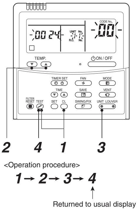
| Indoor unit data | CODE No. | Data name | Unit |
| 01 | Room temperature (Remote controller) | °C | |
| 02 | Indoor suction temperature (TA) | °C | |
| 03 | Indoor heat exchanger (Coil) temperature (TCJ) | °C | |
| 04 | Indoor heat exchanger (Coil) temperature (TC) | °C | |
| * 07 | Indoor fan revolution frequency | rpm | |
| * F2 | Indoor fan calculated operation time | ×100h | |
| F3 | Filter sign time | ×1h | |
| * F8 | Indoor discharge temperature*1 | °C |
| Outdoor unit data | CODE No. | Data name | Unit |
| 60 | Outdoor heat exchanger (Coil) temperature (TE) | °C | |
| 61 | Outside temperature (TO) | °C | |
| 62 | Compressor discharge temperature (TD) | °C | |
| 63 | Compressor suction temperature (TS) | °C | |
| 65 | Heat sink temperature (THS) | °C | |
| 6A | Operation current (× 1/10) | A | |
| * 6D | Outdoor heat exchanger (Coil) temperature (TL) | °C | |
| * 70 | Compressor operation frequency | rps | |
| * 72 | Outdoor fan revolution frequency (Lower) | rpm | |
| * 73 | Outdoor fan revolution frequency (Upper) | rpm | |
| F1 | Compressor calculated operation time | ×100h |
The CODE No. with * marks in the above table are displayed only on the indoor units of 4 series models and after.
(4 series indoor units mean RAV-SM1404UT-E for example.).

3 Push UNIT LOVER button to select the indoor unit to be monitored. Each data of the indoor unit and its outdoor units can be monitored.

4 Pushing TEST button returns the status to the usual display.
*1 The indoor discharge temperature of CODE No. [F8] is the estimated value from TC or TCJ sensor.
Use this value to check discharge temperature at test run.
(A discharge temperature sensor is not provided to this model.)
- The data value of each item is not the real time, but value delayed by a few seconds to ten-odd seconds.
8-2-4. Check Code List (Outdoor)
O: Go on, @: Flash, ●: Go off ALT (Alternate): Alternate flashing when there are two flashing LED SIM (Simultaneous): Simultaneous flashing when there are two flashing LED
| Remote controller indication | Sensor lamp part | Representative defective position | Detection | Explanation of error contents | Automatic reset | Operation continuation | |||
| Block indication | |||||||||
| Operation Timer Ready Flash | |||||||||
| F04 | Og | Og | ALT | Outdoor unit Discharge temp. sensor (TD) error | Outdoor | Open/Short of discharge temp. sensor was detected. | ✘ | ✘ | |
| F06 | Og | Og | ALT | Outdoor unit Temp. sensor (TE, TS, TL) error | Outdoor | Open/Short of heat exchanger temp. sensor was detected.Miswiring between TE sensor and TS sensor | ✘ | ✘ | |
| F08 | Og | Og | ALT | Outdoor unit Outside temp. sensor (TO) error | Outdoor | Open/Short of outside temp. sensor was detected. | ○ | ○ | |
| F07 | Og | Og | ALT | Outdoor unit Temp. sensor (TL) error | Outdoor | Open/Short of heat exchanger temp. sensor was detected. | ✘ | ✘ | |
| F12 | Og | Og | ALT | Outdoor unit Temp. sensor (TS) error | Outdoor | Open/Short of suction temp. sensor was detected. | ✘ | ✘ | |
| F13 | Og | Og | ALT | Outdoor unit Temp. sensor (TH) error | Outdoor | Open/Short of heat sink temp. sensor (Board installed) was detected. | ✘ | ✘ | |
| F15 | Og | Og | ALT | Outdoor unit Misconnection of temp. sensor (TE, TS) | Outdoor | Misconnection of outdoor heat exchanger temp. sensor and suction temp. sensor was detected. | ✘ | ✘ | |
| F31 | Og | Og | SIM | Outdoor unit EEPROM error | Outdoor | Outdoor PC. board part (EEPROM) error was detected. | ✘ | ✘ | |
| H01 | ● | ● | ● | Outdoor unit Compressor break down | Outdoor | When reached min-Hz by current release control, short-circuited current (Idc) after DC excitation was detected. | ✘ | ✘ | |
| H02 | ● | ● | ● | Outdoor unit Compressor lock | Outdoor | Compressor lock was detected. | ✘ | ✘ | |
| H03 | ● | ● | ● | Outdoor unit Current detection circuit error | Outdoor | Current detection circuit error | ✘ | ✘ | |
| H04 | ● | ● | ● | Outdoor unit Case thermostat operation | Outdoor | Case thermostat operation was detected. | ✘ | ✘ | |
| L10 | Og | Og | SIM | Outdoor unit Setting error of service P.C. board type | Outdoor | When outdoor service P.C. board was used, model type select jumper setting was inappropriate. | ✘ | ✘ | |
| L29 | Og | Og | SIM | Outdoor unit Other outdoor unit error | Outdoor | 1) Defective parts on outdoor P.C. board (MCU communication, EEPROM, TH sensor error)2) When outdoor service P.C. board was used, model type selection was inappropriate.3) Other error (Heat sink abnormal overheat, gas leak, 4-way valve inverse error) was detected. | ✘ | ✘ | |
| P03 | Og | ● | Og | Outdoor unit Discharge temp. error | Outdoor | Error was detected by discharge temp. release control. | ✘ | ✘ | |
| P04 | Og | ● | Og | Outdoor unit High pressure system error, Power supply voltage error | Outdoor | When case thermostat worked, error was detected by high release control from indoor/outdoor heat exchanger temp. sensor. Power supply voltage error | ✘ | ✘ | |
| P05 | Og | ● | Og | Alt Power supply error | Outdoor | Power supply voltage error | ✘ | ✘ | |
| P07 | Og | ● | Og | Alt Outdoor unit Heat sink overheat | Outdoor | Abnormal overheat was detected by outdoor heat sink temp. sensor. | ✘ | ✘ | |
| P15 | Og | ● | Og | Alt Gas leak detection | Outdoor | Abnormal overheat of discharge temp. or suction temp. was detected. | ✘ | ✘ | |
| P20 | Og | ● | Og | Alt Outdoor unit High pressure system error | Outdoor | Error was detected by high release control from indoor/outdoor heat exchanger temp. sensor. | ✘ | ✘ | |
| P22 | Og | ● | Og | Alt Outdoor unit Inverter Idc operation | Outdoor | Error (Over-current, lock, etc.) was detected on outdoor fan drive circuit. | ✘ | ✘ | |
| P26 | Og | ● | Og | Alt Outdoor unit Inverter Idc operation | Outdoor | Short-circuited protective operation of compressor drive circuit element (G-Tr /IGBT) worked. | ✘ | ✘ | |
| P29 | Og | ● | Og | Alt Outdoor unit Position detection error | Outdoor | Position detection error of compressor motor was detected. | ✘ | ✘ | |
| E01 | Og | ● | ● | No remote controller master unitRemote controller communication error | Remote controller | Signal was not received from indoor unit.Main remote controller was not set. (including 2 remote controllers) | — | — | |
| E02 | Og | ● | ● | Remote controller send error | Remote controller | Signal cannot be sent to indoor unit. | — | — | |
| E03 | Og | ● | ● | Regular communication error between indoor and remote controller | Indoor | No communication from remote controller and network adapter | ○ | ✘ | |
| E04 | ● | ● | Og | Indoor/Outdoor serial error | Indoor | Serial communication error between indoor and outdoor | ○ | ✘ | |
| E08 | Og | ● | ● | Duplicated indoor addresses | ◇ | Same address as yours was detected. | ○ | ✘ | |
| E09 | Og | ● | ● | Duplicated main remote controllers | Remote controller | In 2-remote controller control, both were set as master.(Indoor master unit stops warning and follower unit continues operation.) | ✘ | ✘ | |
| E10 | Og | ● | ● | Communication error between CPU | Indoor | MCU communication error between main motor and micro computer | ○ | △ | |
| E18 | Og | ● | ● | Regular communication error between master and follower indoor units | Indoor | Regular communication was impossible between master and follower indoor units.Communication between twin master (Main unit) and follower (sub unit) was impossible. | ○ | ✘ | |
| L03 | Og | ● | Og | Duplicated indoor master units | ◇ | Indoor There are multiple master units in a group. | ✘ | ✘ | |
| L07 | Og | ● | Og | There is group cable in individual indoor unit. | ◇ | Indoor When even one group connection indoor unit exists in individual indoor unit | ✘ | ✘ | |
| L08 | Og | ● | Og | Sim Unset indoor group address | ◇ | Indoor Indoor address group was unset. | ✘ | ✘ | |
| L09 | Og | ● | Og | Sim Unset indoor capacity | Indoor | Capacity of indoor unit was unset. | ✘ | ✘ | |
| L30 | Og | ○ | Og | Sim Outside error input to indoor unit (Interlock) | Indoor | Abnormal stop by CN80 outside error input | ✘ | ✘ | |
| P19 | Og | ● | Og | 4-way valve inverse error | Indoor Outdoor | In heating operation, error was detected by temp. down of indoor heat exchanger or temp. up of TE, TS. | ○ | ✘ | |
When this warning was detected before group construction/address check finish at power supply was turned on, the mode shifts automatically to AUTO address setup mode.
O: Go on, @: Flash, ●: Go off ALT (Alternate): Alternate flashing when there are two flashing LED SIM (Simultaneous): Simultaneous flashing when there are two flashing LED
| Remote controller indication | Sensor lamp part | Representative defective position | Detection | Explanation of error contents | Automatic reset | Operation continuation | |||
| Block indication | |||||||||
| Operation Timer Ready Flash | |||||||||
| F01 | ◎ | ◎ | ● | ALT | Indoor unit Heat exchanger sensor (TCJ) error | Indoor | Open/Short of heat exchanger (TCJ) was detected. | ○ | × |
| F02 | ◎ | ◎ | ● | ALT | Indoor unit Heat exchanger sensor (TC) error | Indoor | Open/Short of heat exchanger (TC) was detected. | ○ | × |
| F10 | ◎ | ◎ | ● | ALT | Indoor unit Room temp. sensor (TA) error | Indoor | Open/Short of room temp. (TA) was detected. | ○ | × |
| F29 | ◎ | ◎ | ● | SIM | Indoor unit Other indoor P.C. board error | Indoor | EEPROM error (Other error may be detected. If no error, automatic address is repeated. | × | × |
| P01 | ● | ◎ | ◎ | ALT | Indoor unit Indoor fan error | Indoor | Indoor AC fan error was detected. (Fan thermal relay worked.) | × | × |
| P10 | ● | ◎ | ◎ | ALT | Indoor unit Overflow detection | Indoor | Float switch worked. | × | × |
| P12 | ● | ◎ | ◎ | ALT | Indoor unit Indoor fan error | Indoor | Indoor fan error (Over-current / Lock, etc.) was detected. | × | × |
| P31 | ◎ | ● | ◎ | ALT | Other indoor unit error | Indoor | Other indoor under condition of warning in group. E03/L07/L03/L08 warning | ○ | × |
| — | By unit with warning No. | ALT | Error in indoor group | Network adapter | Sub remote controller error in a group (Details of remote controller are displayed with unit No. Only central control side is displayed.) | — | — | ||
| — | — | LAN system communication error | Network adapter/Center | Communication error of central control system signal * Is not displayed on the remote controller | ○ | ○ | |||
| L20 | ◎ | ○ | ◎ | SIM | LAN system communication error | Network adapter/Center | Duplicated indoor address of central control system communication | ○ | × |
| — | — | There are multiple communication adapters. | Network adapter | There are multiple communication adapters on remote controller communication line. | ○ | ○ | |||
Error mode detected by indoor unit
| Operation of diagnostic function | Judgment and measures | |||
| Check code | Cause of operation | Status of air conditioner | Condition | |
| E03 | No communication from remote controller (including wireless) and communication adapter | Stop (Automatic reset) | Displayed when error is detected | 1. Check cables of remote controller and communication adapters. • Remote controller LCD display OFF (Disconnection) • Central remote controller [97] check code |
| E04 | The serial signal is not output from outdoor unit to indoor unit. • Miswiring of inter-unit wire • Defective serial sending circuit on outdoor P.C. board • Defective serial receiving circuit on indoor P.C. board | Stop (Automatic reset) | Displayed when error is detected | 1. Outdoor unit does not completely operate. • Inter-unit wire check, correction of miswiring • Check outdoor P.C. board. Correct wiring of P.C. board. 2. When outdoor unit normally operates Check P.C. board (Indoor receiving / Outdoor sending). |
| E08 | Duplicated indoor unit address | Stop | Displayed when error is detected | 1. Check whether remote controller connection (Group/Individual) was changed or not after power supply turned on (Finish of group construction/Address check). * If group construction and address are not normal when the power has been turned on, the mode automatically shifts to address setup mode. (Resetting of address) |
| L03 | Duplicated indoor master unit | |||
| L07 | There is group wire in individual indoor unit. | |||
| L08 | Unset indoor group address | |||
| L09 | Unset indoor capacity | Stop | Displayed when error is detected | 1. Set indoor capacity (CODE No. (DN) = 11) |
| L30 | Abnormal input of outside interlock | Stop | Displayed when error is detected | 1. Check outside devices. 2. Check indoor P.C. board. |
| P10 | Float switch operation • Float circuit, Disconnection, Coming-off, Float switch contact error | Stop | Displayed when error is detected | 1. Trouble of drain pump 2. Clogging of drain pump 3. Check float switch. 4. Check indoor P.C. board. |
| P12 | Indoor DC fan error | Stop | Displayed when error is detected | 1. Position detection error 2. Over-current protective circuit of indoor fan driving unit operated. 3. Indoor fan locked. 4. Check indoor P.C. board. |
| P19 | 4-way valve system error • After heating operation has started, indoor heat exchangers temp. is down. | Stop (Automatic reset) | Displayed when error is detected | 1. Check 4-way valve. 2. Check 2-way valve and check valve. 3. Check indoor heat exchanger (TC/TCJ). 4. Check indoor P.C. board. |
| P31 | Own unit stops while warning is output to other indoor units. | Stop (Follower unit) (Automatic reset) | Displayed when error is detected | 1. Judge follower unit while header unit is [E03], [L03], [L07] or [L08]. 2. Check indoor P.C. board. |
| F01 | Coming-off, disconnection or short of indoor heat exchanger temp. sensor (TCJ) | Stop (Automatic reset) | Displayed when error is detected | 1. Check indoor heat exchanger temp. sensor (TCJ). 2. Check indoor P.C. board. |
| F02 | Coming-off, disconnection or short of indoor heat exchanger temp. sensor (TC) | Stop (Automatic reset) | Displayed when error is detected | 1. Check indoor heat exchanger temp. sensor (TC). 2. Check indoor P.C. board. |
| F10 | Coming-off, disconnection or short of indoor heat exchanger temp. sensor (TA) | Stop (Automatic reset) | Displayed when error is detected | 1. Check indoor heat exchanger temp. sensor (TA). 2. Check indoor P.C. board. |
| F29 | Indoor EEPROM error • EEPROM access error | Stop (Automatic reset) | Displayed when error is detected | 1. Check indoor EEPROM. (including socket insertion) 2. Check indoor P.C. board. |
| E10 | Communication error between indoor MCU • Communication error between fan driving MCU and main MCU | Stop (Automatic reset) | Displayed when error is detected | 1. Check indoor P.C. board. |
| E18 | Regular communication error between indoor aster and follower units and between main and sub units | Stop (Automatic reset) | Displayed when error is detected | 1. Check remote controller wiring. 2. Check indoor power supply wiring. 3. Check indoor P.C. board. |
The check code has been ramified from 4 series and after.
The ramified check code is displayed only when both the indoor unit and the outdoor unit are 4 series and after. (Ex. Combination of RAV-SM1404UT-E with RAV-SP1404AT8-E)
When the indoor unit is 3 series and before, the conventional check code is displayed.
(Ex. Combination of RAV-SM1402CT-E and RAV-SP1404AT8-E: Outdoor unit only is 4 series.)
| Operation of diagnostic function | Judgment and measures | ||||
| Check code | Cause of operation | Status of air conditioner | Condition | ||
| Indoor unit | |||||
| before 3 series | after 4 series | ||||
| F04 | F04 | Disconnection, short of discharge temp. sensor (TD) | Stop | Displayed when error is detected | 1. Check discharge temp. sensor (TD).2. Check outdoor P.C. board (MCC-1599). |
| F06 | F06 | Disconnection, short of outdoor temp. sensor (TE) | Stop | Displayed when error is detected | 1. Check temp. sensor (TE).2. Check outdoor P.C. board (MCC-1599). |
| F07 | Disconnection, short of outdoor temp. sensor (TL) | Stop | Displayed when error is detected | 1. Check temp. sensor (TL).2. Check outdoor P.C. board (MCC-1599). | |
| F12 | Disconnection, short of suction temp. sensor (TS) | Stop | Displayed when error is detected | 1. Check suction temp. sensor (TS).2. Check outdoor P.C. board (MCC-1599). | |
| F15 | Miss-mounting of outdoor temp. sensor (TE, TS) | Stop | Displayed when error is detected | 1. Check temp. sensor (TE, TS).2. Check outdoor P.C. board (MCC-1599). | |
| F08 | F08 | Disconnection, short of outside temp. sensor (TO) | Continue | Displayed when error is detected | 1. Check outside temp. sensor (TO).2. Check outdoor P.C. board (MCC-1599). |
| L29 | F13 | Disconnection, short of heat sink temp. sensor (TH) | Stop | Displayed when error is detected | 1. Check outdoor P.C. board (MCC-1599). (Q201 is incorporated in TH sensor.) |
| F31 | Outdoor P.C. EEPROM error | Stop | Displayed when error is detected | 1. Check outdoor P.C. board (MCC-1599). | |
| L10 | Unset jumper of service P.C. board | Stop | Displayed when error is detected | 1. Outdoor service P.C. boardCheck model type setting jumper wire. | |
| L29 | Communication error between outdoor P.C. board MCU | Stop | Displayed when error is detected | 1. Check outdoor P.C. board(MCC-1596,MCC-1597,MCC-1599).2. Connection check between CN802 of MCC-1599 and CN504 of MCC-1597, and also connection check between CN505 of MCC-1597 and CN851 of MCC-1596. | |
| P07 | Heat sink overheat error* Heat sink temp. sensor detected over specified temperature. | Stop | Displayed when error is detected | 1. Check screw tightening between PC. Board and heat sink and check radiator grease (MCC-1596).2. Check heat sink blast path. | |
| P15 | Detection of gas leak* Discharge temp. sensor (TD), Suction temp. sensor (TS) detected temperature over specified temp. | Stop | Displayed when error is detected | 1. Check gas leak, recharge2. Check full open of service valve.3. Check PMV (Pulse Motor Valve).4. Check broken pipe.5. Check discharge temp. sensor (TD), suction temp. sensor (TS). | |
| P19 | 4-way valve inverse error* After heating operation has started, indoor heat exchanger temp. lowers under the specified temp.* After heating operation has started, outdoor heat exchanger / suction temp. rises over the specified temp. | Stop | Displayed when error is detected | 1. Check operation of 4-way valve.2. Check outdoor heat exchanger (TE), suction temp. sensor (TS).3. Check indoor heat exchanger sensor (TC).4. Check 4-way valve coil.5. Check PMV (Pulse Motor Valve). | |
| H01 | H01 | Compressor break down* Although operation has started, operation frequency decreases and operation stops. | Stop | Displayed when error is detected | 1. Check power supply voltage. (AC342 to 457V)2. Overload operation of refrigerating cycle |
| H02 | H02 | Compressor lock* Over-current detection after compressor start-up | Stop | Displayed when error is detected | 1. Trouble of compressor (Lock, etc.): Replace compressor.2. Wiring error of compressor (Open phase) |
| H03 | H03 | Current detection circuit error | Stop | Displayed when error is detected | 1. Check outdoor P.C. board (MCC-1596). (AC current detection circuit) |
| P05 | Open phase of 3-phase power supply | Stop | Displayed when error is detected | 1. Check open phase of 3-phase power supply. 2. Black lead wire to be connected to CN03 of MCC-1596 does not pass through T611. | |
| P03 | P03 | Discharge temp. error * Discharge temp. (TD) over specified value was detected. | Stop | Displayed when error is detected | 1. Check refrigerating cycle (Gas leak) 2. Trouble of electronic expansion valve 3. Check discharge temp. sensor (TD). |
| P04 | H04 | Case thermostat operation * Abnormal overheat of compressor | Stop | Displayed when error is detected | 1. Check case thermostat and connector. 2. Check gas leak, recharge 3. Check full open of service valve. 4. Check PMV (Pulse Motor Valve). 5. Check broken pipe. |
| P04 | High pressure SW system error | Stop | Displayed when error is detected | 1. Check service valves are fully opened. (Gas side, Liquid side) 2. Check of outdoor fan operation. 3. Check motor error of outdoor fan. 4. Check clogging of outdoor PMV. 5. Check clogging of heat exchanger in indoor/outdoor units. 6. Short-circuit status of suction/discharge air in outdoor unit. 7. Check outdoor P.C. board error. 8. Check fan system error (Cause of air volume drop) at indoor side. 9. Check PMV opening status in indoor unit. | |
| P05 | Power supply voltage error | Stop | Displayed when error is detected | 1. Check power supply voltage. AC342 to 457V | |
| P20 | High pressure protective operation • During cooling operation, outdoor temp. sensor (TL) detected temperature over specified temp. • During heating operation, indoor temp. sensor (TC, TCJ) detected temperature over specified temp. | Stop | Displayed when error is detected | 1. Check outdoor heat exchanger sensor (TL). 2. Check indoor heat exchanger sensor (TC, TCJ). 3. Check full open of service valve. 4. Check indoor/outdoor fan. 5. Check PMV (Pulse Motor Valve). 6. Check clogging and short circuit of indoor/outdoor heat exchanger. 7. Overcharge of refrigerant. Recharge | |
| P22 | P22 | Outdoor fan system error | Stop | Displayed when error is detected | 1. Check lock of fan motor. 2. Check power supply voltage between L2 and N. AC198 to 264V 3. Check outdoor P.C. board. |
| P26 | P26 | Short-circuit error of compressor driving element | Stop | Displayed when error is detected | 1. When performing operation while taking-off compressor wire, P26 error occurs. Check control P.C. board (MCC-1596). 2. When performing operation while taking-off compressor wire, an error does not occur. (Compressor rare short) |
| P29 | P29 | Position detection circuit error | Stop | Displayed when error is detected | 1. Check control P.C. board (MCC-1596). |
Error mode detected by remote controller or central controller (TCC-LINK)
| Operation of diagnostic function | Judgment and measures | |||
| Check code | Cause of operation | Status of air conditioner | Condition | |
| Not displayed at all (Operation on remote controller is impossible.) | No communication with master indoor unit • Remote controller wiring is not correct. • Power of indoor unit is not turned on. • Automatic address cannot be completed. | Stop | — | Power supply error of remote controller, Indoor EEPROM error 1. Check remote controller inter-unit wiring. 2. Check remote controller. 3. Check indoor power wiring. 4. Check indoor P.C. board. 5. Check indoor EEPROM. (including socket insertion) → Automatic address repeating phenomenon generates. |
| E01 *2 | No communication with master indoor unit • Disconnection of inter-unit wire between remote controller and master indoor unit (Detected by remote controller side) | Stop (Automatic reset) * If center exists, operation continues. | Displayed when error is detected | Receiving error from remote controller 1. Check remote controller inter-unit wiring. 2. Check remote controller. 3. Check indoor power wiring. 4. Check indoor P.C. board. |
| E02 | Signal send error to indoor unit (Detected by remote controller side) | Stop (Automatic reset) * If center exists, operation continues. | Displayed when error is detected | Sending error of remote controller 1. Check sending circuit inside of remote controller. → Replace remote controller. |
| E09 | There are multiple main remote controllers. (Detected by remote controller side) | Stop (Sub unit continues operation.) | Displayed when error is detected | 1. In 2-remote controllers (including wireless), there are multiple main units. Check that there are 1 main remote controller and other sub remote controllers. |
| L20 Central controller L20 | Duplicated indoor central addresses on communication of central control system (Detected by indoor/central controller side) | Stop (Automatic reset) | Displayed when error is detected | 1. Check setting of central control system network address. (Network adapter SW01) 2. Check network adapter P.C. board. |
| * *3 Central controller (Send) C05 (Receive) C06 | Communication circuit error of central control system (Detected by central controller side) | Continues (By remote controller) | Displayed when error is detected | 1. Check communication wire / miswiring 2. Check communication (U3, U4 terminals) 3. Check network adapter P.C. board. 4. Check central controller (such as central control remote controller, etc.) 5. Check terminal resistance. (TCC-LINK) |
| Central controller P30 | Indoor Gr sub unit error (Detected by central controller side) | Continuation/Stop (According to each case) | Displayed when error is detected | Check the check code of the corresponding unit from remote controller. |
*2 The check code cannot be displayed by the wired remote controller.
(Usual operation of air conditioner becomes unavailable.)
For the wireless models, an error is notified with indication lamp.
*3 This trouble is related to communication of remote controller (A, B), central system (TCC-LINK U3, U4), and [E01], [E02], [E03], [E09] or [E18] is displayed or no check display on the remote controller according to the contents.
8-2-5. Diagnostic Procedure for Each Check Code (Outdoor Unit)
1) This section describes the diagnostic method for each check code displayed on the remote controller.
2) In some cases, a check code indicates multiple symptoms.
In this case, confirm LED display on the outdoor P.C. board to narrow the contents to be confirmed.
3) The check code on the remote controller is displayed only when the same error occurred continuously by multiple times while LED of the outdoor P.C. board displays even an error which occurred once.
Therefore the display on the remote controller may differ from that of LED.
LED display on outdoor P.C. board
Dip switch setup
- When turning on 1) only of SW803, the latest error is displayed. As the memory is stored, it can be confirmed even if the power supply is turned off once. (excluding outside temp. sensor (TO) error)
- When the work finished or the outdoor temp. sensor (TO) error was found, turn off all of SW803. (The error which occurs at present is displayed.)
Only 1) of SW803 is ON.
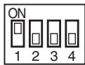
All SW803 are OFF. (Initial status)
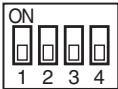
Display selection
- When even a LED of D800 to D804 (Yellow) goes on, error occurrence is indicated.
- If pushing the button switch SW800 for 1 second under the above condition, the yellow LED is displayed with flashing.
- When pushing SW800 for 1 second again, the status returns to
. - The error contents can be confirmed by combining
and .
⇌
(No error) (Error occurred) (Push SW800)
D805 (Green)
D804 (Yellow)
D803 (Yellow)
D802 (Yellow)
D801 (Yellow)
D800 (Yellow)
O
O
O
O
O
O
(Example of discharge temp. sensor error)
| Check code | Outdoor LED display | Check and troubleshooting (Item without special mention indicates part of outdoor unit.) | |
| [E04] | — | [Indoor/Outdoor communication error] | |
| Is setting of group address of remote controller correct? NO Check CODE No. [14]. | |||
| YES Are inner wiring and inter-unit cables (1, 2, 3) normal? NO Correct wiring and inter-unit cable. | |||
| YES Are connection of CN01 of MCC-1599 and wiring of terminal blocks (1, 2, 3) normal? NO Correct wiring of connectors and terminal blocks. | |||
| YES Does D502 (Orange LED) flash after power supply is turned on again? NO Check indoor P.C. board. Defect → Replace | |||
| YES Check outdoor P.C. board (MCC-1599). Defect → Replace | |||
| [F04] | <Display 1> <Display 2> | [Discharge temp. sensor (TD) error] | |
| ○ ○ | Is CN603 connection normal? Is resistance value of TD sensor normal? NO Sensor error → Replace | ||
| ○ ● | Yes | ||
| ● ● | Correct connector. Sensor error → Replace | ||
| ● ● | Check outdoor P.C. board (MCC-1599). Defect → Replace | ||
| [F06] | · There is a possibility that it is one of the following errors. Confirm LED on outdoor P.C. board to judge which error it is. Heat exchanger temp. sensor (TE) error, Heat exchanger temp. sensor (TL) error, Suction temp. sensor (TS) error, Miswiring of heat exchanger sensor (TE, TS) | ||
| <Display 1> <Display 2> | Heat exchanger temp. sensor (TE) error] | ||
| ○ ○ | Is CN601 connection normal? Is resistance value of TE sensor normal? NO Sensor error → Replace | ||
| ○ ● | Correct connector. Sensor error → Replace | ||
| ● ● | Check outdoor P.C. board (MCC-1599). Defect → Replace | ||
| ● ● | Check outdoor P.C. board (MCC-1599). Defect → Replace | ||
| ○ ○ | [Heat exchanger temp. sensor (TL) error] → Refer to [F07] column. | ||
| ○ ○ | [Heat exchanger temp. sensor (TL) error] → Refer to [F07] column. | ||
| ○ ● | Correct connector. Sensor error → Replace | ||
| ● ● | Check outdoor P.C. board (MCC-1599). Defect → Replace | ||
| ● ● | Check outdoor P.C. board (MCC-1599). Defect → Replace | ||
| [F07] | <Display 1> <Display 2> | [Heat exchanger temp. sensor (TL) error] | |
| ○ ○ | Is CN604 connection normal? Is resistance value of TL sensor normal? NO Sensor error → Replace | ||
| ○ ● | Correct connector. Sensor error → Replace | ||
| ● ● | Check outdoor P.C. board (MCC-1599). Defect → Replace | ||
| ○ ○ | Check outdoor P.C. board (MCC-1599). Defect → Replace | ||
| [F08] | <Display 1> <Display 2> | [Outside air temp. sensor (TO) error] | |
| ○ ○ | Is CN602 connection normal? Is resistance value of TO sensor normal? NO Correct connector. Sensor error → Replace | ||
| ○ | Yes Check outdoor P.C. board (MCC-1599). Defect → Replace | ||
| [F12] | <Display 1> <Display 2> | [Suction temp. sensor (TS) error] | |
| ○ ○ | Is CN600 connection normal? Is resistance value of TS sensor normal? NO Correct connector. Sensor error → Replace | ||
| ○ | Yes Check outdoor P.C. board (MCC-1599). Defect → Replace | ||
| [F13] | <Display 1> <Display 2> | [Heat sink temp. sensor (TH) error] | |
| ○ ○ | Check outdoor P.C. board (MCC-1599). Defect → Replace | ||
| [F15] | <Display 1> <Display 2> | [Miswiring of heat exchanger sensor (TE, TS)] | |
| ○ ○ | Is mounting status of TE and TS sensors normal? NO Correct sensor mounting. | ||
| ○ | Yes Correct connector. Sensor error → Replace | ||
| ○ | Yes No Correct connector. Sensor error → Replace | ||
| ○ | Yes Check outdoor P.C. board (MCC-1599). Defect → Replace | ||
| [F31] | <Display 1> <Display 2> | [EEPROM error] Check outdoor P.C. board (MCC-1599). Defect → Replace | |
| [H01] | <Display 1> <Display 2> | [Compressor break down] Is power supply voltage normal? AC342 to 457V NO Correct power supply line. YES Is wire connection normal? Compressor lead (Board side, Compressor side), Reactor lead, Power supply lead NO Check wire connection and correct it. YES Yes Is it not abnormal overload? YES Correct and clear the cause. NO Check outdoor P.C. board (MCC-1596). Defect → Replace | |
| [H02] | <Display 1> <Display 2> | [Compressor lock] Is power supply voltage normal? AC342 to 457V NO Correct power supply line. YES Is wire connection normal? Compressor lead (Board side, Compressor side), Reactor lead, Power supply lead NO Check wire connection and correct it. YES Yes Check outdoor P.C. board. Defect → Replace NO Is there no refrigerant stagnation? NO Compressor lock → Replace YES Does PMV normally operate? NO Check TE, TS sensors and PMV. Defect → Replace Yes Check outdoor P.C. board (MCC-1596). Defect → Replace | |
| [H03] | <Display 1> <Display 2> | [Current detection circuit error] Check outdoor P.C. board (MCC-1596). Defect → Replace | |
| <Display 1> <Display 2> | [Power supply error (Vdc)] → Refer to [P05] column. | ||
| [H04] | <Display 1> <Display 2> | [Case thermostat operation] Are CN609 connection and case thermostat normal? NO Correct connector. Case thermostat error → Replace Is cooling/heating operation available when short-circuiting case thermostat? No Check outdoor P.C. board (MCC-1599). Defect → Replace Is there no gas leak? Repair defectives position. Recharge refrigerant. Yes Open valve fully. Is PMV normal? No Correct defective position. Replace defective part. Check crushed or broken pipe. Defect → Correct and Replace | |
| [L10] | <Display 1> <Display 2> | [Unset model type] : Only when service P.C. board is used Cut jumper line according to the explanation sheet packaged with the service P.C. board. | |
| [L29] | * There is a possibility that it is one of the following errors. Confirm LED on outdoor PC. board to judge which error it is. Communication error between MCU, Heat sing temp. sensor (TH) error, EEPROM error, Unset model type, Heat sink overheat error, Gas leak detection, 4-way valve inverse error | ||
| <Display 1> <Display 2> | [Communication error between MCU]1. Connection check between CN802 of MCC-1599 and CN504 of MCC-1597 and also connection check between CN505 of MCC-1597 and CN851 of MCC-1596.2. Check outdoor P.C. board (MCC-1596, MCC-1597, MCC-1599). Defect → Replace | ||
| <Display 1> <Display 2> | [Heat sink temp. sensor (TH) error] → Refer to [F13] column. | ||
| <Display 1> <Display 2> | [EEPROM error] → Refer to [F31] column. | ||
| <Display 1> <Display 2> | [Unset model type] → Refer to [L10] column. | ||
| <Display 1> <Display 2> | [Heat sink overheat error] → Refer to [P07] column. | ||
| <Display 1> <Display 2> | [Gas leak detection] → Refer to [P15] column. | ||
| <Display 1> <Display 2> | [4-way valve inverse error] → Refer to [P19] column. | ||
| [P03] | <Display 1> <Display 2> | [Discharge temp. error] | |
| ○ ○ ● | Is there no gas leak? Is refrigerant charge amount adequate? YES No Repair defective position. Recharge refrigerant. | ||
| ○ ○ ● | Is PMV normal? NO Repair defective position. Replace defective part. | ||
| ○ ○ ● | Is it not abnormal overload? YES Correct and clear the cause. Sensor error → Replace | ||
| ○ ○ ● | Is CN603 connection normal? NO Correct connector. Sensor error → Replace | ||
| ○ ○ ● | Check outdoor PC. board (MCC-1599). Defect → Replace | ||
| [P04] | * There is a possibility that it is one of the following errors. Confirm LED on outdoor PC. board to judge which error it is. (1) high-pressure SW system error, (2) power supply error (Vdc), (3) high-pressure protective operation, (4) case thermo operation. | ||
| <Display 1> <Display 2> | [High pressure SW system error] Power supply error (Vdc), High pressure protective operation, Case thermostat operation. | ||
| ○ ○ ● | Doesn't high pressure switch operate? NO Wiring check, Correct. | ||
| ○ ○ ● | Are parts of high pressure switch normal? NO Parts check Defective → Replace | ||
| ○ ○ ● | Is service valve fully opened? NO Open service valve fully. | ||
| ○ ○ ● | Reset the power supply and then do a trial operation according to the season. B) ← Cooling operation C) ← Heating operation | ||
| ○ ○ ● | Check Comp. IPDU PC board Defective → Replace | ||
| ○ ○ ● | Does cooling outdoor fan normally operate? NO Is there no fan breakage or coming-off? NO Repair defective position. Fan IPDU, Fan motor, Wiring. | ||
| ○ ○ ● | Is there any element which blocks heat exchanger of the outdoor unit? YES Elimination of blocking element | ||
| ○ ○ ● | Overcharge of refrigerant/ Clogging/Pipe breakage/ Abnormal overload | ||
| [P04] | Heating operation Does the heating indoor fan normally operate? NO YES Is there any element which blocks indoor heat exchanger? ① Filter clogging ② Clogging of heat exchanger ③ Short circuit NO Clogging by refrigerant overcharge/pipe breakage/Abnormal overload Clogging by refrigerant overcharge/pipe breakage/ Abnormal overload Replace indoor P.C. board Defective → Replace Case thermostat operation] → Refer to [H04] column. | ||
| <Display 1> <Display 2> | ○ ○ ○ ● ○ ○ ○ ○ ○ ○ ○ ○ ○ ○ ○ ○ ○ ○ ○ ○ ○ ○ ○ ○ ○ ○ ○ ○ ○ ○ ○ ○ ○ ○ ○ ○ ○ ○ ○ ○ ○ ○ ○ ○ ○ ○ ○ ○ ○ ○ ○ ○ ○ ○ O ○ ○ ○ ○ ○ ○ ○ ○ ○ ○ ○ ○ ○ ○ ○ ○ ○ ○ ○ ○ ○ ○ ○ ○ ○ ○ ○ ○ ○ ○ ○ ○ ○ ○ ○ ○ ○ ○ ○ ○ ○ ○ ○ ○ ○ ○ ○ ○ ○ × ○ ○ ○ ○ ○ ○ ○ ○ ○ ○ ○ ○ ○ ○ ○ ○ ○ ○ ○ ○ ○ ○ ○ ○ ○ ○ ○ ○ ○ ○ ○ ○ ○ ○ ○ ○ ○ ○ ○ ○ ○ ○ ○ ○ ○ ○ ○ ○ ○ ± ± ± ± ± ± ± ± ± ± ± ± ± ± ± ± ± ± ± ± ± ± ± ± ± ± ± ± ± ± ± ± ± ± ± ± ± ± ± ± ± ± ± ± ± ± ± ± ± ± ○ ○ ○ ○ ○ ○ ○ ○ ○ ○ ○ ○ ○ ○ ○ ○ ○ ○ ○ ○ ○ ○ ○ ○ ○ ○ ○ ○ ○ ○ ○ ○ ○ ○ ○ ○ ○ ○ ○ ○ ○ ○ ○ ○ ○ ○ ○ ○ ○ √ ○ ○ ○ ○ ○ ○ ○ ○ ○ ○ ○ ○ ○ ○ ○ ○ ○ ○ ○ ○ ○ ○ ○ ○ ○ ○ ○ ○ ○ ○ ○ ○ ○ ○ ○ ○ ○ ○ ○ ○ ○ ○ ○ ○ ○ ○ ○ ○ ○ ★ ○ ○ ○ ○ ○ ○ ○ ○ ○ ○ ○ ○ ○ ○ ○ ○ ○ ○ ○ ○ ○ ○ ○ ○ ○ ○ ○ ○ ○ ○ ○ ○ ○ ○ ○ ○ ○ ○ ○ ○ ○ ○ ○ ○ ○ ○ ○ ○ ○ 0 0 0 0 0 0 0 0 0 0 0 0 0 0 0 0 0 0 0 0 0 0 0 0 0 0 0 0 0 0 0 0 0 0 0 0 0 0 0 0 0 0 0 0 0 0 0 0 0 0 ○ ○ ○ ○ ○ ○ ○ ○ ○ ○ ○ ○ ○ ○ ○ ○ ○ ○ ○ ○ ○ ○ ○ ○ ○ ○ ○ ○ ○ ○ ○ ○ ○ ○ ○ ○ ○ ○ ○ ○ ○ ○ ○ ○ ○ ○ ○ ○ ○ ∞ ○ ○ ○ ○ ○ ○ ○ ○ ○ ○ ○ ○ ○ ○ ○ ○ ○ ○ ○ ○ ○ ○ ○ ○ ○ ○ ○ ○ ○ ○ ○ ○ ○ ○ ○ ○ ○ ○ ○ ○ ○ ○ ○ ○ ○ ○ ○ ○ ○ ← ← ← ← ← ← ← ← ← ← ← ← ← ← ← ← ← ← ← ← ← ← ← ← ← ← ← ← ← ← ← ← ← ← ← ← ← ← ← ← ← ← ← ← ← ← ← ← ← ← → → → → → → → → → → → → → → → → → → → → → → → → → → → → → → → → → → → → → → → → → → → → → → → → → → ← ← ← ← ← ← ← ← ← ← ← ← ← ← ← ← ← ← ← ← ← ← ← ← ← ← ← ← ← ← ← ← ← ← ← ← ← ← ← ← ← ← ← ← ← ← ← ← ← × × × × × × × × × × × × × × × × × × × × × × × × × × × × × × × × × × × × × × × × × × × × × × × × × × ○ ○ ○ ○ ○ ○ ○ ○ ○ ○ ○ ○ ○ ○ ○ ○ ○ ○ ○ ○ ○ ○ ○ ○ ○ ○ ○ ○ ○ ○ ○ ○ ○ ○ ○ ○ ○ ○ ○ ○ ○ ○ ○ ○ ○ ○ ○ ○ × × × × × × × × × × × × × × × × × × × × × × × × × × × × × × × × × × × × × × × × × × × × × × × × × √ √ √ √ √ √ √ √ √ √ √ √ √ √ √ √ √ √ √ √ √ √ √ √ √ √ √ √ √ √ √ √ √ √ √ √ √ √ √ √ √ √ √ √ √ √ √ √ √ √ × × × × × × × × × × × × × × × × × × × × × × × × × × × × × × × × × × × × × × × × × × × × × × × × × ← ← ← ← ← ← ← ← ← ← ← ← ← ← ← ← ← ← ← ← ← ← ← ← ← ← ← ← ← ← ← ← ← ← ← ← ← ← ← ← ← ← ← ← ← ← ← ← ← √ | ||
| [P05] | <Display 1> <Display 2> | [Power supply error (Voltage error)] | |
| ○ | Is there no open phase of the power supply? YES Correct wiring. | ||
| ○ | NO | ||
| ○ | Is there no down or up of power supply voltage? YES Confirm electric construction, etc. | ||
| ○ | NO Check outdoor P.C. board (MCC-1600). Defect → Replace | ||
| [P07] | <Display 1> <Display 2> | [Heat sink overheat error] | |
| ○ | Is there no loosening of screws of motor drive element of outdoor P.C. board (MCC-1596) Q201? Apply radiation grease to objective part. Retightening of screws. | ||
| ○ | Did not forget to apply radiation grease to rear side of Q201? No NO Remove blocking matter. Correct short-circuit. | ||
| ○ | Is not the ventilation flue of the heat sink blocked? Yes Check outdoor P.C. board (MCC-1596). Defect → Replace | ||
| ○ | Gas leak detection | ||
| [P15] | <Display 1> <Display 2> | [Gas leak detection] | |
| ○ | Is there no gas leak? NO Repair defective position. Recharge refrigerant. | ||
| ○ | Yes NO Correct defective position. Replace defective part. | ||
| ○ | Is PMV normal? NO Open valve fully. | ||
| ○ | Is valve fully opened? YES Open valve fully. | ||
| ○ | Is there no crushed pipe? YES Correct and replace piping. | ||
| ○ | No OK Check connector. Sensor error → Replace Check outdoor P.C. board (MCC-1599). Defect → Replace | ||
| [P19] | <Display 1> <Display 2> | [4-way valve inverse error] | |
| ○ | Is operation of 4-way valve normal? YES Temperature sensor check TE sensor CN601 TS sensor CN600 Indoor TC sensor Defect → Correct and repair | ||
| ○ | NO Replace coil of 4-way valve. | ||
| ○ | Is power supplied to 4-way valve coil? NO Replace coil of 4-way valve. | ||
| ○ | Check operation of outdoor I/F (CDB) P.C. board. Check outdoor P.C. board. Defect → replace OK Check 4-way valve. Defect → Replace | ||
| [P20] | <Display 1> <Display 2> | [High pressure protective operation] | |
| ○ ○◎●●●○○○○○○○○○○○○○○○○○○○○○○○○○○○○○○○○○○○○○○○○○○○○○○○○○○○○○○○○○○○○○○○○○○○○○○○○○○○○○○○○○○○○○○○○○○○○○○○○○○○○ | |||
| Heating season Heating operation | |||
| Is there no problem on outdoor TL sensor? (Measurement of resistance value) NO Replace sensor. | |||
| Is there no crack or loosening of outdoor fan? NO Replace sensor. | |||
| Does not the outdoor fan perform abnormal operation? NO Replace sensor as [P22] error. | |||
| Is there no element which interfere heat exchange of outdoor unit? Clogging of heat exchanger YES Short circuit Eliminate interfering element. | |||
| Check overcharge of refrigerant, clogging of cycle, broken pipe, abnormal overload, etc. Defect → Correct defective position. | |||
| Does indoor fan normally operate? NO Are indoor fan motor and connector normal? NO Replace defective position. | |||
| Yes Yes Repair defective position. | |||
| Are resistance values of indoor TC and TCJ sensors normal? NO Replace sensor. | |||
| Yes Check indoor P.C. board. Defect → Replace | |||
| Is there no element which interfere heat exchange of indoor unit? Clogging of filter Clogging of heat exchanger Eliminate interfering element. | |||
| NO Check overcharge of refrigerant, clogging of cycle, broken pipe, abnormal overload, etc. Defect → Correct defective position. | |||
| [P22] | <Display 1> <Display 2> ○ ○ ● ○ ○ ○ | [Fan system error] Is there no problem on power supply voltage? (342 to 457V) NO Check wiring construction. Ask repair of power supply. YES Does the fan rotate without trouble when rotating shaft of fan motor with hands during power-OFF? Is there no problem on coil resistance of fan motor? Between red and white lead wire :12 to 20Ω Between white and black lead wire :12 to 20Ω Between black and red lead wire :12 to 20Ω NO Replace fan motor. Check outdoor PC. board (MCC-1597). Defect → Replace | |
| Single operation check for outdoor fan 1) Set SW804 of Dip switch as the following figure and then push SW801 for approx. 1 second to check single operation of outdoor fan. Use this method to check which fan, upper or lower fan, has a trouble. · When pushing SW801 for 1 second again or 2 minutes passed, the fan stops. 2) After check, turn off all Dip switch SW804. Outdoor fan single operation SW804 ON 1 2 3 4 Push | |||
| [P26] | <Display 1> <Display 2> ○ ○ ● ○ ○ ○ | [Short-circuit of compressor drive element] Is there no problem on connection of compressor lead or reactor? (Check referring to Wiring diagram.) NO Correct wiring. YES The same error does not occur in operation without compressor lead. NO Replace outdoor P.C. board. YES Check compressor. (Rear short, etc.) Defect → Replace | |
| [P29] | <Display 1> <Display 2> ○ ○ ● ○ ○ ○ | [Position detection circuit error] Check outdoor P.C. board (MCC-1596). Defect → Replace | |
| — No code | <Display 1> <Display 2> ○ ○ ● ○ ○ ○ | [Other error] Compressor disorder due to sudden change of load, etc. * Although the display of outdoor LED outputs, the unit automatically restarts and error is not determined. * LED display also may output due to negative phase of compressor or wire coming-off. | |
TA, TC, TCJ, TE, TS, TO sensors
Representative value
| Temperature (°C) | Resistance value (kΩ) | ||
| (Minimum value) | (Standard value) | (Maximum value) | |
| 0 | 32.33 | 33.80 | 35.30 |
| 10 | 19.63 | 20.35 | 21.09 |
| 20 | 12.23 | 12.59 | 12.95 |
| 25 | 9.75 | 10.00 | 10.25 |
| 30 | 7.764 | 7.990 | 8.218 |
| 40 | 5.013 | 5.192 | 5.375 |
| 50 | 3.312 | 3.451 | 3.594 |
| 60 | 2.236 | 2.343 | 2.454 |
| 70 | 1.540 | 1.623 | 1.709 |
| 80 | 1.082 | 1.146 | 1.213 |
| 90 | 0.7740 | 0.8237 | 0.8761 |
| 100 | 0.5634 | 0.6023 | 0.6434 |
TD,TL sensors
Representative value
| Temperature (°C) | Resistance value (kΩ) | ||
| (Minimum value) | (Standard value) | (Maximum value) | |
| 0 | 150.5 | 161.3 | 172.7 |
| 10 | 92.76 | 99.05 | 105.6 |
| 20 | 58.61 | 62.36 | 66.26 |
| 25 | 47.01 | 49.93 | 52.97 |
| 30 | 37.93 | 40.22 | 42.59 |
| 40 | 25.12 | 26.55 | 28.03 |
| 50 | 17.00 | 17.92 | 18.86 |
| 60 | 11.74 | 12.34 | 12.95 |
| 70 | 8.269 | 8.668 | 9.074 |
| 80 | 5.925 | 6.195 | 6.470 |
| 90 | 4.321 | 4.507 | 4.696 |
| 100 | 3.205 | 3.336 | 3.468 |
TA, TC, TCJ, TE, TS, TO sensors
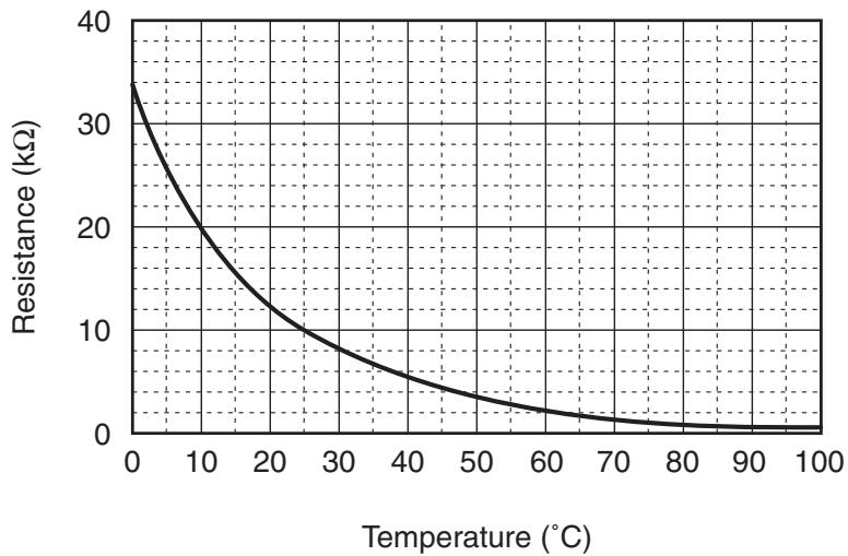
aannnne aennnnnne
TD,TL sensors
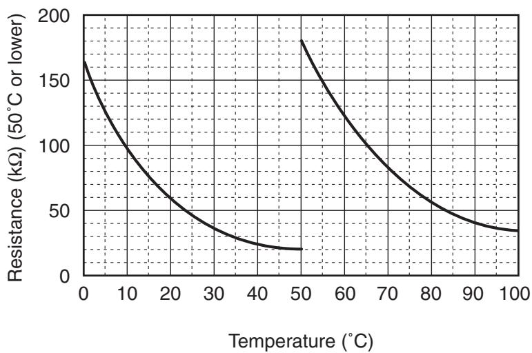
0 5 0 5 0 20
* As TH sensor (Outdoor unit heat sink temp. sensor) is incorporated in the outdoor control P.C. board, the resistance value cannot be measured.
Table Inspection of outdoor unit main parts
| No. | Parts name | Checking procedure | |
| 1 | Compressor (Model:DA422A3F-27M) | Measure the resistance value of each winding by using the tester. | |
| Position | Resistance value | ||
| Red-White | 0.79 ± 0.04 Ω | ||
| White-Black | |||
| Black-Red | |||
| Under 20°C | |||
| 2 | Outdoor fan motor (Model:ICF-280-A100-1) | Measure the resistance value of each winding by using the tester. | |
| Position | Resistance value | ||
| Red-White | 14.8 ± 1.5 Ω | ||
| White-Black | |||
| Black-Red | |||
| Under 20°C | |||
| 3 | 4-way valve coil (Cooling/heating switching) (Model:STF-01AJ502E1) | Measure the resistance value of each winding by using the tester. | |
| Resistance value | |||
| 1435 ± 144 Ω | |||
| Under 20°C | |||
9. SETUP AT LOCAL SITE AND OTHERS
9-1. Calling of Error History
The error contents in the past can be called.
1 Push SET + TEST buttons simultaneously for 4 seconds or more to call the service check mode.
Service Check goes on, the CODE No. 01 is displayed, and then the content of the latest alarm is displayed. The number and error contents of the indoor unit in which an error occurred are displayed.
2 In order to monitor another error history, push the set temperature / buttons to change the error history No. (CODE No.).
CODE No. (Latest) CODE No. (Old)
NOTE : 4 error histories are stored in memory.
3 Pushing TEST button returns the display to usual display.
REQUIREMENT
Do not push button, otherwise all the error histories of the indoor unit are deleted.
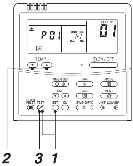
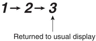
9-2. Group Control Operation
In a group control, operation of maximum 8 indoor units can be controlled by a remote controller.
The indoor unit connected with outdoor unit (Individual/Master of twin) controls room temperature according to setting on the remote controller.
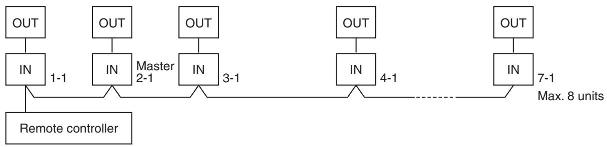
1. Display range on remote controller
The setup range (Operation mode/Air volume select/Setup temp) of the indoor unit which was set to the master unit is reflected on the remote controller.
2. Address setup
Turn on power of the indoor unit to be controlled in a group within 3 minutes after setting of automatic address. If power of the indoor unit is not turned on within 3 minutes (completion of automatic address setting), the system is rebooted and the automatic address setting will be judged again.
1) Connect 3 In/Out cables surely.
2) Check line address/indoor address/group address of the unit one by one.
3) The unit No. (line/indoor gout address) which have been set once keep the present status as a rule if the unit No. is not duplicated with one of another unit.
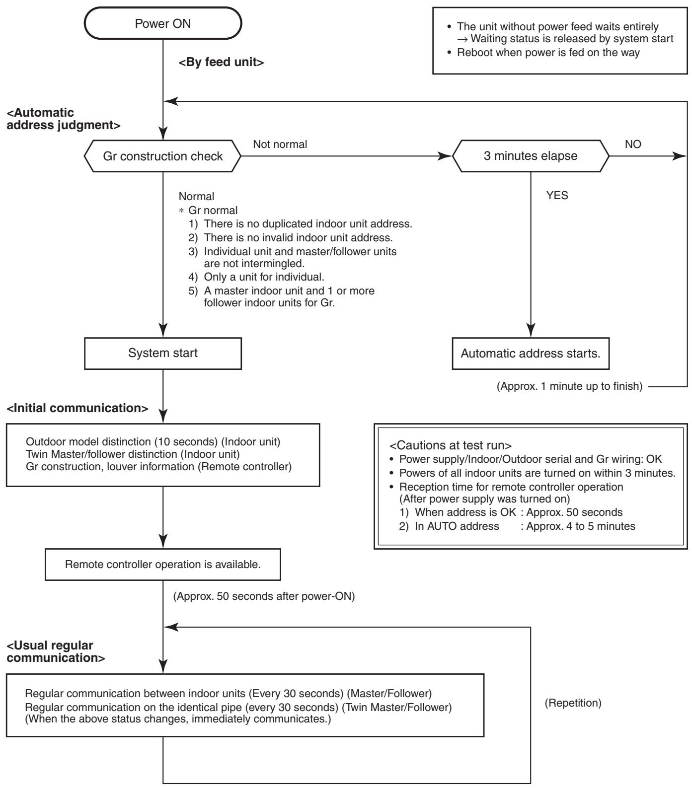
- In a group operation, if the indoor unit which was fed power after judgment of automatic address cannot receive regular communication from the master unit and regular communication on identical pipe within 120 seconds after power was turned on, it reboots (system reset).
The operation starts from judgment of automatic address (Gr construction check) again. (If the address of the master unit was determined in the previous time, the power fed to the master unit and reboot works, the master unit may change though the indoor unit line address is not changed.)
9-3. Outdoor Unit
9-3-1. Various Setting on Outdoor Unit (Existing piping, Power save, Cooling-only, etc.)
The following settings are available by DIP switch setup and jumper line setup.
| Function | Set position | Control contents | |||||
| High static pressure setup | SW802 ON 1 2 3 4 | Turn the switch to ON when mounting a duct to the discharge port of the outdoor unit. Add 3 taps to the upper limit value of the outdoor fan tap. The operation is performed with (Max: Upper fan: 890 rpm / Lower fan: 910 rpm (WF)). In this case, the upper limit value of static pressure for duct is 5Pa or less on 25°C degrees and please use straight duct. In this case, the outdoor noise level may increase. | |||||
| Existing piping setup | High static pressure setup Existing piping setup Power save setup Snow-proof fan control * all are OFF at shipment. | Turn the switch to ON when ∅19.1 is used for the existing pipe. In this case, the heating capacity may lower according to outside temp. and indoor temp. in heating operation. | |||||
| Power save setup | Turn the switch to ON when using the power save function. The control to lower the compressor frequency (Approx. -10%) is performed by indoor heat exchanger temp. in heating operation. | ||||||
| Snow-proof fan control | When snow enters from clearance of the fan guard or heat exchanger into blast path and it is accumulated, the control to prevent generation of motor lock is validated. When outside temp. is below 4°C though the compressor stops, the outdoor fan operates with W5. | ||||||
| Defrost time change | J805, J806 | The defrost interval is cut to shorten it than the standard status. For contents of control and cutting method, refer to Section 7-10. Defrost control. | |||||
| Max. frequency change | J807 | When it is needed to lower the maximum value of the compressor frequency, cut the jumper line. Max. frequency at heating is lowered. In this case the Max. capacity decreases. Max. frequency of compressor | |||||
| Model | SP110 | SP140 | SP160 | ||||
| COOL | HEAT | COOL | HEAT | COOL | |||
| Standard status | 53.4 | 100.2 | 64.2 | 100.2 | 74.4 | ||
| When J807 is cut | 53.4 | 69.6 | 64.2 | 75.0 | 74.4 | ||
| Cooling-only setup | J808 | When using the air conditioner as a cooling-only conditioner, cut the jumper line. (An air conditioner can be changed to cooling-only conditioner by “0F” of DN code on the remote controller.) | |||||
9-3-2. Service Support Function (LED Display, Switch Operation)
1. Outline
A various setup and operation check can be performed by DIP switches at 3 positions
(SW802, SW803, SW804) and the pushdown button switches (SW800, SW801) at 2 positions.
Operation part
| Part No. | Specifications | Operation contents |
| SW800 | Pushdown button switch | Exchanges the displayed contents of LED (D800 to D804) on the outdoor control P.C. board. |
| SW803 | DIP switch | |
| SW801 | Pushdown button switch | Performs the specific operation to check maintenance. |
| SW804 | DIP switch | |
| SW802 | DIP switch | Performs various initial settings. (Refer to 9-3-1.) |
Display part
| Part No. | Specifications | Operation contents |
| D502 | Orange LED | Indoor/Outdoor communication (Serial communication) signal display(Receive signal from indoor signal) |
| D503 | Green LED | Indoor/Outdoor communication (Serial communication) signal display(Send signal from outdoor signal) |
| D800 to D804 | Yellow LED | Error displayWhen all SW803 are OFF, or when any of D800 to D804 goes on, LED displays that the outdoor controller detects an error.When status of SW803 is other than OFF, various indications are displayed. |
| D805 | Green LED | Power-ON displayWhen the power of the outdoor unit is turned on, LED goes on.When SW801 and SW804 operate the specific operation, LED flashes. |
- All LED are colorless when it goes off.
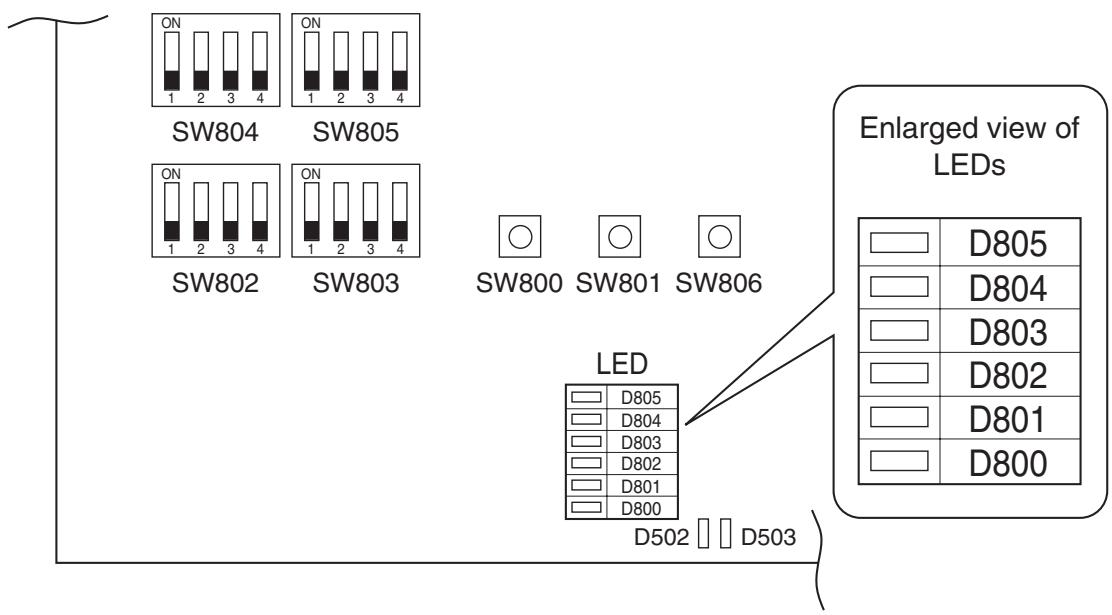
9-3-3. Others
1. Selection of LED display (SW800, SW803 operation)
1) Display selection list
The displayed contents of LED D800 to D804 on the outdoor control P.C. board can be exchanged by operation of SW803.
| Switch | Function / Contents | Refer |
| SW803 ON 1 2 3 4 | Error display (Error generating at present) Error generating at present is displayed. This switch goes off when an error does not generate. | Refer to 2) |
| SW803 ON 1 2 3 4 | Error display (The latest error: Latest error including present) After error status was cleared, the error which generated before can be confirmed by this setting. (Reconfirmation is available even if power supply was turned off once.) • If an error generates at present, the same contents as those of error which is generating at present are displayed. • Only error of TO sensor is not displayed by this setting. (Confirm it by setting of error which is generating at present.) | Refer to 2) |
| TD SW803 ON 1 2 3 4 TO SW803 ON 1 2 3 4 TA SW803 ON 1 2 3 4 TC SW803 ON 1 2 3 4 TCJ SW803 | Temperature sensor display The detected value of temperature sensor is displayed. | Refer to 3) |
| SW803 ON 1 2 3 4 | Current display The current value which flows in the outdoor unit is displayed. | Refer to 3) |
| SW803 ON 1 2 3 4 | Compressor operation frequency display The operation frequency of the compressor is displayed. | Refer to 3) |
| SW803 ON 1 2 3 4 | PMV opening display The opening of PMV (Pulse Motor Valve) is displayed. | Refer to 3) |
| SW803 ON 1 2 3 4 | Ps sensor display Detected Ps sensor is displayed. | Refer to 3) |
2) Error display
The error which is generating at present and the latest error (Latest error information including present) can be confirmed by lighting LED D800 toD804 on the outdoor control P.C. board.
a) When all DIP switch SW803 are OFF, the status of error which is generating at present is displayed.
b) < 1> only of DIP switch SW803 is turned on, the error which generated before
(Latest error information including present) is displayed.a)
c) If there is an error, any of LED D800 to D804 goes on. (Display 1)
d) When pushing the pushdown button switch SW800 for approx. 1 second, the display is exchanged. (Display 2)
e) When pushing SW800 again or after 2 minutes, the status returns to that of Display ①
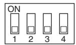
Present error SW803
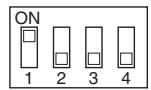
Latest error SW803
(Legend)
0800
(Yellow)

D801
(Yellow)

D802
(Yellow)

D803
Yellow)

D804
Yellow)

D805
(Green)
:Go off,

: Go on, : Flash
| Display 1)(Initial display) | Display 2)(SW800 operation) | Error contents | Wired remote controller Error code |
| ●●●●●○ | ●●●●●○ | Normal | — |
| ○○●●○○ | ●●●●●○ | Discharge temp. sensor (TD) error | F04 |
| ●●●●●○ | Heat exchanger temp. sensor (TE) error | F06 | |
| ●●●●●○ | Heat exchanger temp. sensor (TL) error | F06, F07 | |
| ●●●●●○ | Outside temp. sensor (TO) error | F08 | |
| ●●●●●○ | Suction temp. sensor (TS) error | F06, F12 | |
| ●●●●●○ | Heat sink temp. sensor (TH) error | F13, L29 | |
| ●●●●●○ | Heat exchanger sensor (TE, TS) miswiring | F06, F15 | |
| ●●●●●○ | EEPROM error | F31, L29 | |
| ●●○●○○ | ●●●●●○ | Compressor break down | H01 |
| ●●●●●○ | Compressor lock | H02 | |
| ●●●●●○ | Current detection circuit error | H03 | |
| ●●●●●○ | Case thermostat operation | H04, P04 | |
| ●○○●○○ | ●●●●●○ | Model unset | L10, L29 |
| ●●●●●○ | Communication error between MCU | L29 | |
| ●●●●●○ | Other error (Compressor disorder, etc.) | Error is not determined. | |
| ○○○●○○ | ●●●●●○ | Discharge temp. error | P03 |
| ●●●●●○ | High pressure SW system error | P04 | |
| ●●●●●○ | Power supply error | P04, P05 | |
| ●●●●●○ | Heat sink overheat error | P07, L29 | |
| ●●●●●○ | Gas leak detection | P15, L29 | |
| ●●●●●○ | 4-way valve reverse error | P19, L29 | |
| ●●●●●○ | High pressure protective operation | P04, P20 | |
| ●●●●●○ | Fan system error | P22 | |
| ●●●●●○ | Driving element short-circuit | P26 | |
| ●●●●●○ | Position detection circuit erro | P29 |
- As the error code displayed on the wired remote controller may differ according to type of indoor model, multiple codes are described.
3) Sensor, current, compressor operation frequency, PMV opening display
The values detected by the controller, such as temperature sensor or current value are simply confirmed.
(Legend)

D800
(Yellow)

D801
(Yellow)

D802
(Yellow)

D803
(Yellow)

D804
(Yellow)

D805
(Green)
:Go off, :Go on
| Item setup LED display | Temperature sensor (°C) | Current (A) | Compressor operation frequency (rpm) | PMV opening (Pulse) | ||
| TD SW803 ON 1 2 3 4 | TE SW803 ON 1 2 3 4 | TS SW803 ON 1 2 3 4 | ||||
| TO SW803 ON 1 2 3 4 | TL SW803 ON 1 2 3 4 | TH SW803 ON 1 2 3 4 | SW803 ON 1 2 3 4 | SW803 ON 1 2 3 4 | SW803 ON 1 2 3 4 | |
| TA SW803 ON 1 2 3 4 | TC SW803 ON 1 2 3 4 | TCJ SW803 ON 1 2 3 4 | ||||
| ●●●●●●○ | Below -25 | 0 to 0.9 | 0 to 4 | 0 to 19 | ||
| ○●●●●●○ | -25 to -21 | 1 to 1.9 | 5 to 9 | 20 to 39 | ||
| ●○●●●●○ | -20 to -16 | 2 to 2.9 | 10 to 14 | 40 to 59 | ||
| ○○●●●○ | -15 to -11 | 3 to 3.9 | 15 to 19 | 60 to 79 | ||
| ●●○●●○ | -10 to -5 | 4 to 4.9 | 20 to 24 | 80 to 99 | ||
| ○●○●●○ | -5 to -1 | 5 to 5.9 | 25 to 29 | 100 to 119 | ||
| ●○○●●○ | 0 to 4 | 6 to 6.9 | 30 to 34 | 120 to 139 | ||
| ○○○●●○ | 5 to 9 | 7 to 7.9 | 35 to 39 | 140 to 159 | ||
| ●●●○●○ | 10 to 14 | 8 to 8.9 | 40 to 44 | 160 to 179 | ||
| ○●●○●○ | 15 to 19 | 9 to 9.9 | 45 to 49 | 180 to 199 | ||
| ●○●○●○ | 20 to 24 | 10 to 10.9 | 50 to 54 | 200 to 219 | ||
| ○○●○●○ | 25 to 29 | 11 to 11.9 | 55 to 59 | 220 to 239 | ||
| ●●○○●○ | 30 to 34 | 12 to 12.9 | 60 to 64 | 240 to 259 | ||
| ○●○○●○ | 35 to 39 | 13 to 13.9 | 65 to 69 | 260 to 279 | ||
| ●○○○●○ | 40 to 44 | 14 to 14.9 | 70 to 74 | 280 to 299 | ||
| ○○○○●○ | 45 to 49 | 15 to 15.9 | 75 to 79 | 300 to 319 | ||
| ●●●●○○ | 50 to 54 | 16 to 16.9 | 80 to 84 | 320 to 339 | ||
| ○●●●○○ | 55 to 59 | 17 to 17.9 | 85 to 89 | 340 to 359 | ||
| ●○●●○○ | 60 to 64 | 18 to 18.9 | 80 to 84 | 360 to 379 | ||
| ○○●●○○ | 65 to 69 | 19 to 19.9 | 95 to 99 | 380 to 399 | ||
| ●●○●○○ | 70 to 74 | 20 to 20.9 | 100 to 104 | 400 to 419 | ||
| ○●○●○○ | 75 to 79 | 21 to 21.9 | 105 to 109 | 420 to 439 | ||
| ●○○●○○ | 80 to 84 | 22 to 22.9 | 110 to 114 | 440 to 459 | ||
| ○○○●○○ | 85 to 89 | 23 to 23.9 | 115 to 119 | 460 to 479 | ||
| ●●○○○○ | 90 to 94 | 24 to 24.9 | 120 to 124 | 480 to 499 | ||
| ○●●○○○ | 95 to 99 | 25 to 25.9 | 125 to 129 | 500 | ||
| ●○●○○○ | 100 to 104 | 26 to 26.9 | 130 to 134 | — | ||
| ○○●○○○ | 105 to 109 | 27 to 27.9 | 135 to 139 | — | ||
| ●●○○○○ | 110 to 114 | 28 to 28.9 | 140 to 144 | — | ||
| ○●○○○○ | 115 to 119 | 29 to 29.9 | 145 to 149 | — | ||
| ●○○○○○ | Over 120 | 30 to 30.9 | 150 to 154 | — | ||
| ○○○○○○ | Sensor error, unconnected | Over 31 | Over 155 | — | ||
- As TD, TL and TH are sensors for high temperature, there is error at normal temperature or below position.
- For current value, the current for the outdoor unit only is displayed.
4) Specific operation for maintenance check (SW801, SW804)
The following specific operations for the maintenance check are performed by operation of SW801 or SW804.
a) Select DIP switch SW804. (See table below)
b) Push the pushdown button switch SW801 for approx. 1 second.
c) The following functions start. While each function starts, LED D805 (Green) flashes.
d) When pushing the pushdown button switch SW801 again for approx. 1 second, when selecting DIP switch SW804 or when the specified time of each function elapsed, each function stops and LED D805 (Green) returns to the continuous lighting.
| SW804 | Operation when pushdown button switch SW801 is pushed | |
| SW804 ON 1 2 3 4 | Refrigerant recovery operation The outdoor unit performs cooling operation. The indoor unit does not work by this operation alone. Therefore operate the fan beforehand. | |
| SW804 ON 1 2 3 4 | Indoor cooling test run demand The cooling test run is performed. (→ Note 1) | |
| SW804 ON 1 2 3 4 | Indoor heating test run demand The heating test run is performed. (→ Note 1) | |
| SW804 ON 1 2 3 4 | Fan motor forced operation Drive the fan motor forcibly. When pushing SW801 again or when 2 minutes elapsed, the operation returns to the normal control. | [NOTE] Although these operations can be performed even during operation, basically perform operation while the unit stops. If performing this operation during driving the unit, it is dangerous because the pressure may change suddenly. |
| SW804 ON 1 2 3 4 | PMV full open operation Open PMV (Pulse Motor Valve) fully. When pushing SW801 again or when 2 minutes elapsed, the operation returns to the normal control. | |
| SW804 ON 1 2 3 4 | PMV full close operation Close PMV (Pulse Motor Valve) fully. When pushing SW801 again or when 2 minutes elapsed, the operation returns to the normal control. | |
| SW804 ON 1 2 3 4 | PMV middle opening operation Set PMV (Pulse Motor Valve) to middle opening. When pushing SW801 again or when 2 minutes elapsed, the operation returns to the normal control. | |
Note 1) Indoor cooling test run demand / Indoor heating test run demand
Only when combining with the following indoor unit, cooling/heating operation can be performed from the outdoor unit.
Test run is available: Indoor unit of 4 series and after (RAV-SM***4UT-E etc.)
Test run is unavailable: Indoor units other than the above-mentioned indoor units, or indoor units other than above-mentioned indoor units are included in the twin, triple, double twin connection.
Note 2) The forced test run by this setting cannot be cleared on the indoor remote controller.
Be sure to clear the test run by operation of the outdoor unit. (Push SW801 again for 1 second.)
| SW804 | Operation when pushdown button switch SW801 is pushed | |
| SW804 ON 1 2 3 4 | 4-way valve relay operation (For RY700, CN70 check) Turn on 4-way valve power relay (RY700). When pushing SW801 again or when 2 minutes elapsed, the operation returns to the normal control. | [CAUTION] Although these operations can be performed even during operation, basically perform operation while the unit stops. If performing this operation during driving the unit, it is dangerous because the pressure may change suddenly. |
| SW804 ON 1 2 3 4 | Heater output relay operation (For check RY703, CN703 check) Turn on relay for option heater (RY703). When pushing SW801 again or when 2 minutes elapsed, the operation returns to the normal control. | |
| SW804 ON 1 2 3 4 | Outside output relay operation (RY704, CN704) Turn on relay for outside output (RY704). When pushing SW801 again or when 2 minutes elapsed, the operation returns to the normal control. | |
| SW804 ON 1 2 3 4 | Forced start command The indoor unit connected to the system is forcedly started. (The indoor unit starts operation by setting of the operation mode on the remote controller.) | |
| SW804 ON 1 2 3 4 | Forced stop command The indoor unit connected to the system is forcedly stopped. | |
| SW804 ON 1 2 3 4 | Relay operation change for outside output [CAUTION] Do not use this setting. | |
10. ADDRESS SETUP
10-1. Address Setup Procedure
When an outdoor unit and an indoor unit are connected, or when an outdoor unit is connected to each indoor unit respectively in the group operation even if multiple refrigerant lines are provided, the automatic address setup completes with power-ON of the outdoor unit. The operation of the remote controller is not accepted while automatic address works. (Approx. 4 to 5 minutes)
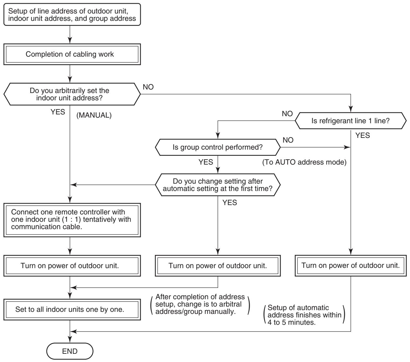
- When the following addresses are not stored in the neutral memory (IC503) on the indoor P.C. board, a test run operation cannot be performed. (Unfixed data at shipment from factory)
| Item code | Data at shipment | Setup data range | |
| Line address | 12 | 0099 | 0001 (No. 1 unit) to 0064 (No. 64 unit) |
| Indoor unit address | 13 | 0099 | 0001 (No. 1 unit) to 0064 (No. 64 unit) Max. value of indoor units in the identical refrigerant line |
| Group address | 14 | 0099 | 0000 : Individual (Indoor units which are not controlled in a group) 0001 : Master unit (1 indoor unit in group control) 0002 : Sub unit (Indoor units other than master unit in group control) |
10-2. Address Setup & Group Control
Indoor unit No. : N - n = Outdoor unit line address N (Max. 30) - Indoor unit address n (Max. 64)
Group address : 0 = Single (Not group control) 1 = Master unit in group control 2 = Sub unit in group control
Master unit (= 1) : The representative of multiple indoor units in group operation sends/receives signals to/from the remote controllers and sub indoor units.
(*) It has no relation with an indoor unit which communicates serially with the outdoor units.)
The operation mode and setup temperature range are displayed on the remote controller LCD. (Except air direction adjustment of louver)
Sub unit (= 2) : Indoor units other than master unit in group operation
Basically, sub units do not send/receive signals to/from the remote controllers.
(Except errors and response to demand of service data)
Header unit (Representative unit) (Master Twin)
: This unit communicates with the indoor unit (follower) which serial-communicates with the outdoor units and sends/receives signal (Command from compressor) to/from the outdoor units as the representative of the cycle control in the indoor units of the identical line address within the minimum unit which configures one of the refrigerating cycles of Twin.
Follower unit (Subordinate unit) (Sub Twin)
: Indoor units excluding the header unit in Twin
This unit communicates with (Header) indoor unit in the identical line address and performs control synchronized with (Header) indoor unit.
This unit does not perform the signal send/receive operation with the outdoor units. :
No judgment for serial signal error.
10-2-1. System Configuration
1. Single
2. Twin
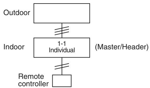
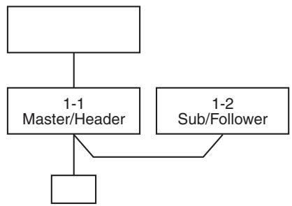
3. Single group operation
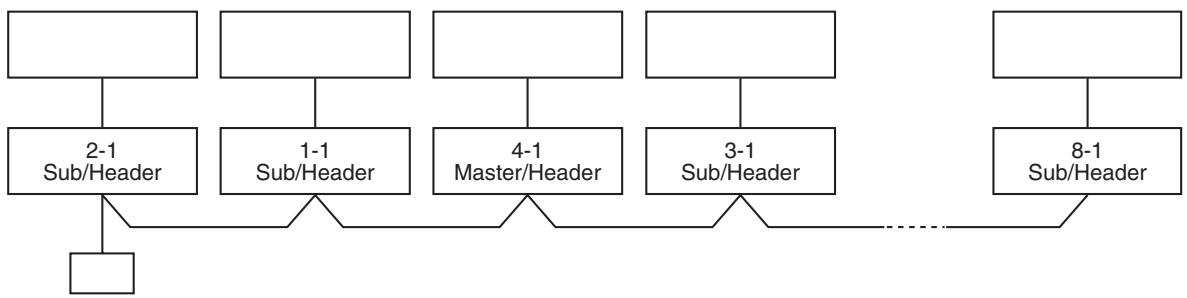
10-2-2. Automatic Address Example from Unset Address (No miswiring)
1. Standard (One outdoor unit)
1) Single
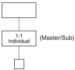
2) Group operation (Twin, Triple operation)
(Multiple outdoor units = Molecule indoor units only with serial communication)
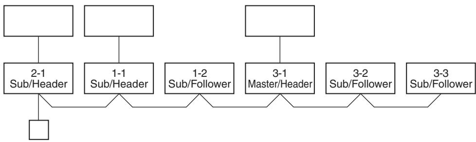
Only turning on source power supply (Automatic completion)
- Header unit: The header unit receives the indoor unit data (thermo status) of the follower (Without identical line address & indoor/outdoor serial) and then finally controls the outdoor compressor matching with its own thermo status.
The header unit sends this command information to the follower unit.
- Follower unit: The follower unit receives the indoor unit data from the header (With identical line address & indoor/outdoor serial) and then performs the thermo operation synchronized with the header unit.
The follower unit sends own thermo ON/OFF demand to the header unit.
(Example)
No. 1-1 header unit sends/receives signal to/from No. 1-2 and No. 1-3 follower units. (It is not influenced by the line 2 or 3 address indoor unit.)
10-2-3. Automatic Address Example from Unset Address (No miswiring)
1. Standard (One outdoor unit)
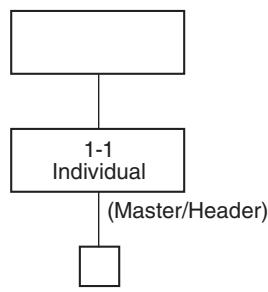
1) Single
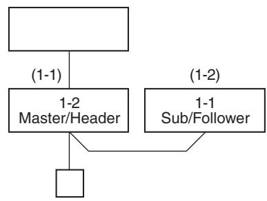
2) Twin
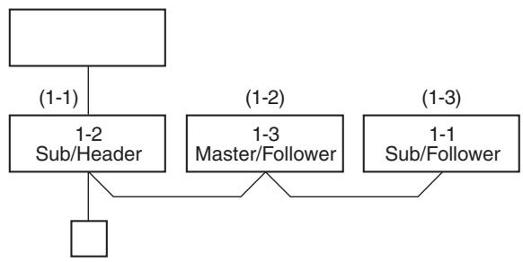
3) Triple (SP160 only)
Only turning on source power supply (Automatic completion)
2. Group operation
(Multiple outdoor units = Multiple indoor units with serial communication only, without twin)
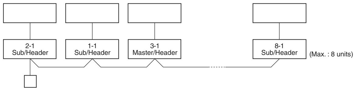
Only turning on source power supply (Automatic completion)
3. Multiple groups operation
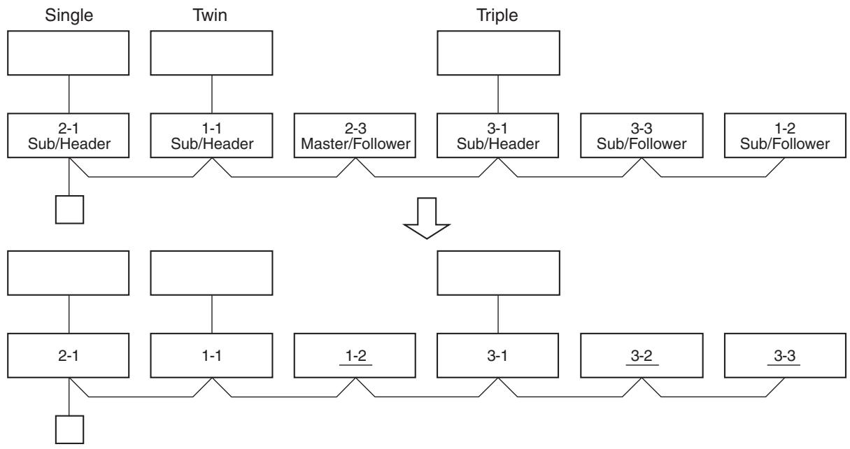
Change is necessary
Manually change addresses of the multiple follower units simultaneously from the remote controller.
10-3. Remote Controller Wiring
- Strip off approx. 9mm the wire to be connected.
- For single system, use non polarity, 2 core wire is used for wiring of the remote controller. (0.5 mm² to 2.0 mm² wires)
- For the synchronous twin, triple system, use 2-conre shield wire (Vinyl cord for microphone 0.5 to 2.0mm^2 ) to conform to the EMC standard.
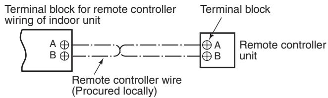
Wiring diagram
- For details of wiring/installation of the remote controller, refer to the Installation Manual enclosed with the remote controller.
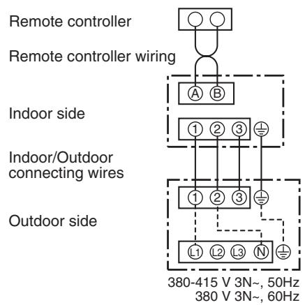
Single system
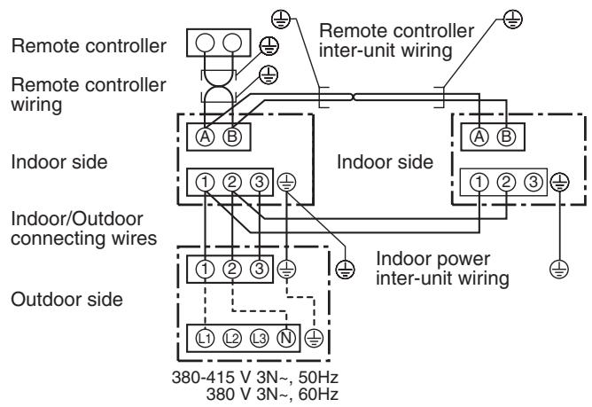
Simultaneous twin system
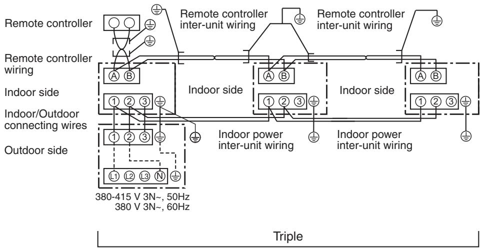
Simultaneous triple system (SP160 only)
10-4. Address Setup (Manual setting from remote controller)
In case that addresses of the indoor units will be determined prior to piping work after cabling work
- Set an indoor unit per a remote controller.
- Turn on power supply.
(Example of 2-lines cabling)
(Real line: Cabling, Broken line: Refrigerant pipe)
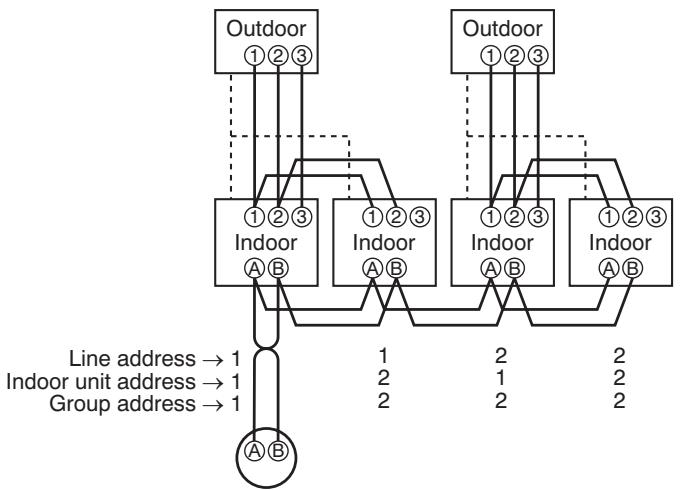
Remote controller
1 Push SET + CL TEST buttons simultaneously for 4 seconds or more.
2 (← Line address) Using the temperature setup / buttons, set /2 to the CODE No.
3 Using timer time / buttons, set the line address.
4 Push SET button. (OK when display goes on.)
5 ( Indoor unit address) Using the temperature setup / buttons, set /3 to the CODE No.
6 Using timer time / buttons, set 1 to the line address.
7 Push SET button. (OK when display goes on.)
8 (← Group address) Using the temperature setup / buttons, set /4 to the CODE No.
9 Using timer time / buttons, set 000 to Individual, 001 to Master unit, and 002 to sub unit.
10 Push SET button. (OK when display goes on.)
11 Push TEST button. Setup completes. (The status returns to the usual stop status.)
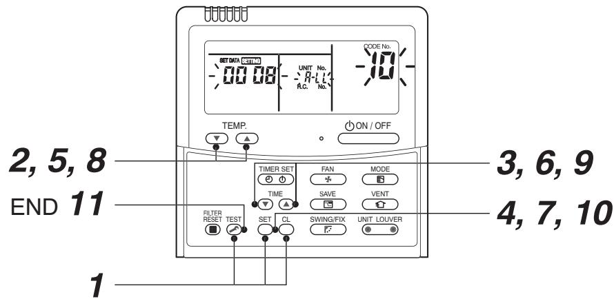
10-5. Confirmation of Indoor Unit No. Position
1. To know the indoor unit addresses though position of the indoor unit body is recognized
- In case of individual operation (Wired remote controller : indoor unit = 1 : 1) (Follow to the procedure during operation)
1 Push ON/OFF button if the unit stops.
2 Push UNIT LOUVER button.
Unit No. 1 - 1 is displayed on LCD.
(It disappears after several seconds.)
The displayed unit No. indicate line address and indoor unit address.
(When other indoor units are connected to the identical remote controller (Group control unit), other unit numbers are also displayed every pushing button.
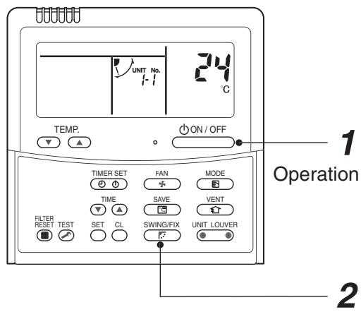
1→2END
2. To know the position of indoor unit body by address
- To confirm the unit No. in the group control
(Follow to the procedure during operation) (in this procedure, the indoor units in group control stop.)
The indoor unit numbers in the group control are successively displayed, and fan, louver, and drain pump of the corresponding indoor unit are turned on. (Follow to the procedure during operation)
1 Push VENT and TEST buttons simultaneously for 4 seconds or more.
- Unit No. ALL is displayed.
- Fans and louvers of all the indoor units in the group control operate.
2 Every pushing button, the unit numbers in the group control are successively displayed.
- The unit No. displayed at the first time indicates the master unit address.
- Fan and louver of the selected indoor unit only operate.
3 Push TEST button to finish the procedure.
All the indoor units in the group control stop.
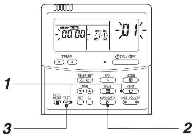
1→2→3END
Aiming in environmental preservation, it is strictly recommended to clean and maintain the indoor/outdoor units of the operating air conditioning system regularly to secure effective operation of the air conditioner.
It is also recommended to maintain the units once a year regularly when operating the air conditioner for a long time.
Check periodically signs of rust or scratches, etc. on coating of the outdoor units.
Repair the defective position or apply the rust resisting paint if necessary.
If an indoor unit operates for approx. 8 hours or more per day, usually it is necessary to clean the indoor/outdoor units once three months at least.
These cleaning and maintenance should be carried out by a qualified dealer.
Although the customer has to pay the charge for the maintenance, the life of the unit can be prolonged.
Failure to clean the indoor/outdoor units regularly will cause shortage of capacity, freezing, water leakage or trouble on the compressor.
| Part name | Object | Contents of check | Contents of maintenance | |
| Indoor | Outdoor | |||
| Heat exchanger | ○ | ○ | • Blocking with dust, damage check | • Clean it when blocking is found. |
| Fan motor | ○ | ○ | • Audibility for sound | • When abnormal sound is heard |
| Filter | ○ | — | • Visual check for dirt and breakage | • Clean with water if dirty • Replace if any breakage |
| Fan | ○ | ○ | • Visual check for swing and balance • Check adhesion of dust and external appearance. | • Replace fan when swinging or balance is remarkably poor. • If a large dust adheres, clean it with brush or water. |
| Suction/Discharge grille | ○ | — | • Visual check for dirt and scratch | • Repair or replace it if deformation or damage is found. |
| Drain pan | ○ | — | • Check blocking by dust and dirt of drain water. | • Clean drain pan, Inclination check |
| Face panel, Louver | ○ | — | • Check dirt and scratch. | • Cleaning/Coating with repair painting |
| External appearance | — | ○ | • Check rust and pealing of insulator • Check sealing and floating of coating film | • Coating with repair painting |
11. REPLACEMENT OF THE SERVICE P.C. BOARD (4316V417) MCC-1599
1. Setting the jumper wires and DIP switches
| Part name | Function | Setting | |
| Jumper wire | J800 to J803 | Model switching | Cut these jumper wires according to the following table. |
| J804 to J811 | Settings | Set these jumper wires to the settings of the P.C. board before replacement | |
| DIP switch | SW802 | Settings | Set SW802 to the setting of the P.C. board before replacement |
| SW803 | LED indication switching | Set SW803 to all OFF. | |
| SW804 | Special operations for service | Set SW804 to all OFF | |
| SW805 | Special operations for service | Set SW805 to all OFF | |
Model switching (J800 to J803)
Since this service P.C. board is available for several models, cut the jumper wires according to the following table. If they are not cut correctly, an error code "L10" or "L29" appears on the wired remote controller and the operation of the air conditioner is disabled.
| Model name | J 800 | J 801 | J 802 | J 803 |
| Factory setting (default) | ○ | ○ | ○ | ○ |
| RAV-SM2244AT8*-E, AT7* | × | ○ | ○ | ○ |
| RAV-SM2804AT8*-E, AT7* | ○ | × | ○ | ○ |
| RAV-SP1104AT8*-E, AT7* | × | × | ○ | ○ |
| RAV-SP1404AT8*-E, AT7* | ○ | ○ | × | ○ |
| RAV-SP1604AT8*-E, AT7* | × | ○ | × | ○ |
| *: Characters that indicate the followingNo. character : Standard modelsZ : For salt-affected areasZG : For heavily salt-affected areas | ○ : Connected,X : Cut | |||
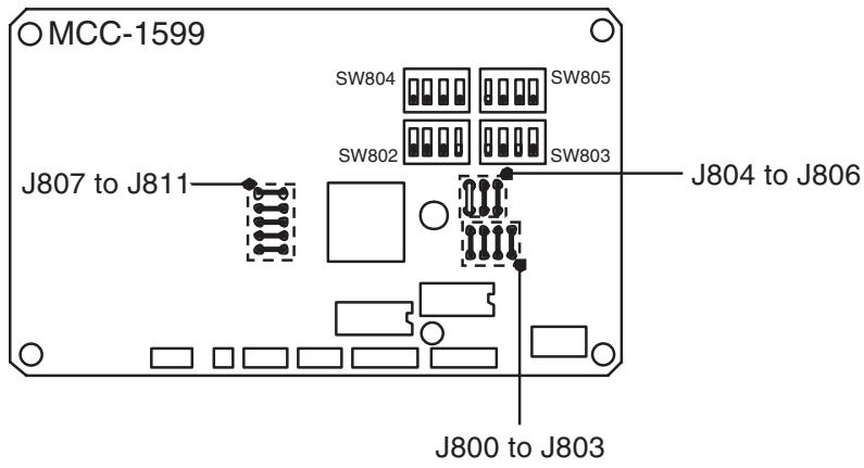
12. HOW TO EXCHANGE COMPRESSOR
12-1. Exchanging Procedure of Compressor (Outline)
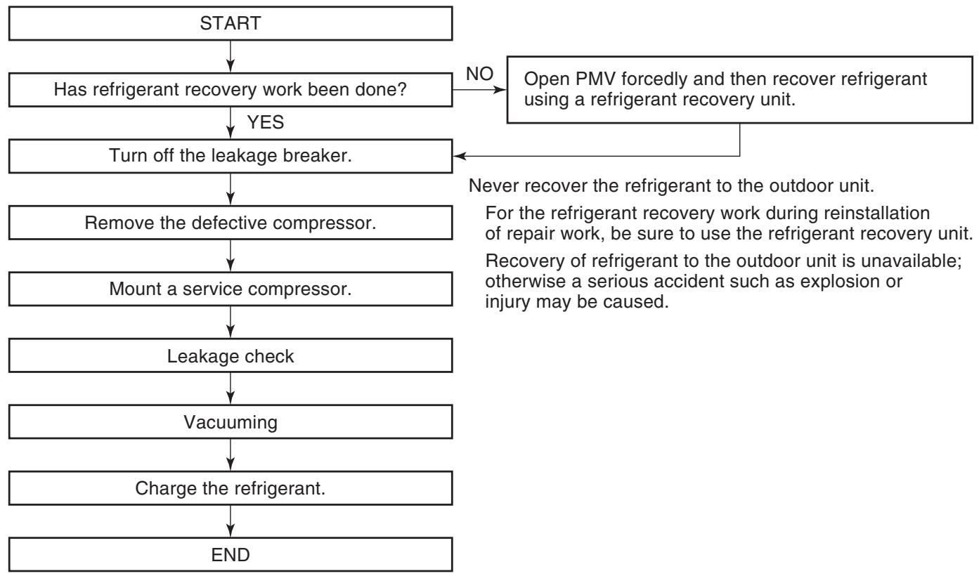
12-2. Exchange of Compressor
For exchange of compressors, refer to (11) Compressor in Section 14. Detachments.
13. INSTALLATION MANUAL
Original instruction
ADOPTION OF NEW REFRIGERANT
This Air Conditioner is a new type that has adopted a new refrigerant HFC (R410A) instead of the conventional refrigerant R22 in order to prevent destruction of the ozone layer.
The air conditioner must be installed, maintained, repaired and removed by a qualified installer or qualified service person. When any of these jobs is to be done, ask a qualified installer or qualified service person to do them for you. A qualified Installer or qualified service person is an agent who has the qualifications and knowledge described in the table below.
short-circuit power Ssc greater than or equal to Ssc (^*1)
Ssc (^*1)
| Model | Ssc (MVA) |
| RAV-SP1104AT8(Z)(ZG)-E | 1.35 |
| RAV-SP1404AT8(Z)(ZG)-E | 1.35 |
| RAV-SP1604AT8(Z)(ZG)-E | 1.35 |
Contents
1 PRECAUTIONS FOR SAFETY
2 ACCESSORY PARTS AND REFRIGERANT 3 INSTALLATION OF NEW REFRIGERANT AIR CONDITIONER
4 INSTALLATION CONDITIONS
5 REFRIGERANT PILING.
6 AIR PURGING
7 ELECTRICAL WORK.
8 EARTHING.
9 FINISHING
10 TEST RUN
11 ANNUAL MAINTENANCE. 12 AND CONSTITUTIONAL OPERATING CONDITIONS
12 AIR CONDITIONER OPEN 10. THEORYTICAL TEST
13 FUNCTIONS TO BE IMPED
14 TROUBLESHOOTING...
15 APPENDIX
| Agent | Qualifications and knowledge which the agent must have |
| Qualified installer | ·The qualified installer is a person who installs, maintains, relocates and removes the air conditioners made by Toshiba Carrier Corporation. He or she has been trained to install, maintain, relocate and remove the air conditioners made by Toshiba Carrier Corporation or, alternatively, he or she has been instructed in such operations by an individual or individuals who have been trained and is thus thoroughly acquainted with the knowledge related to these operations. ·The qualified installer who is allowed to do the electrical work involved in installation, relocation and removal has the qualifications pertaining to this electrical work as stipulated by the local laws and regulations, and he or she is a person who has been trained in matters relating to electrical work on the air conditioners made by Toshiba Carrier Corporation or, alternatively, he or she has been instructed in such matters by an individual or individuals who have been trained and is thus thoroughly acquainted with the knowledge related to this work. ·The qualified installer who is allowed to do the refrigerant handling and piping work involved in installation, relocation and removal has the qualifications pertaining to this refrigerant handling and piping work as stipulated by the local laws and regulations, and he or she is a person who has been trained in matters relating to refrigerant handling and piping work on the air conditioners made by Toshiba Carrier Corporation or, alternatively, he or she has been instructed in such matters by an individual or individuals who have been trained and is thus thoroughly acquainted with the knowledge related to this work. ·The qualified installer who is allowed to work at heights has been trained in matters relating to working at heights with the air conditioners made by Toshiba Carrier Corporation or, alternatively, he or she has been instructed in such matters by an individual or individuals who have been trained and is thus thoroughly acquainted with the knowledge related to this work. |
| Qualified service person | ·The qualified service person is a person who installs, repairs, maintains, relocates and removes the air conditioners made by Toshiba Carrier Corporation. He or she has been trained to install, repair, maintain, relocate and remove the air conditioners made by Toshiba Carrier Corporation or, alternatively, he or she has been instructed in such operations by an individual or individuals who have been trained and is thus thoroughly acquainted with the knowledge related to these operations. ·The qualified service person who is allowed to do the electrical work involved in installation, repair, relocation and removal has the qualifications pertaining to this electrical work as stipulated by the local laws and regulations, and he or she is a person who has been trained in matters relating to electrical work on the air conditioners made by Toshiba Carrier Corporation or, alternatively, he or she has been instructed in such matters by an individual or individuals who have been trained and is thus thoroughly acquainted with the knowledge related to this work. ·The qualified service person who is allowed to do the refrigerant handling and piping work involved in installation, repair, relocation and removal has the qualifications pertaining to this refrigerant handling and piping work as stipulated by the local laws and regulations, and he or she is a person who has been trained in matters relating to refrigerant handling and piping work on the air conditioners made by Toshiba Carrier Corporation or, alternatively, he or she has been instructed in such matters by an individual or individuals who have been trained and is thus thoroughly acquainted with the knowledge related to this work. ·The qualified service person who is allowed to work at heights has been trained in matters relating to working at heights with the air conditioners made by Toshiba Carrier Corporation or, alternatively, he or she has been instructed in such matters by an individual or individuals who have been trained and is thus thoroughly acquainted with the knowledge related to this work. |
Definition of Protective Gear
When the air conditioner is to be transported, installed, maintained, repaired or removed, wear protective gloves and "safety" work clothing. In addition to such normal protective gear, wear the protective gear described below when undertaking the special work detailed
Failure to wear the proper protective gear is dangerous because you will be more susceptible to injury, burns, electric shocks and other injuries.
Warning Indications on the Air Conditioner Unit
| Warning indication | Description | |
| 警告 | WARNING | WARNING |
| ELECTRICAL SHOCK HAZARD Disconnect all remote electric power supplies before servicing. | ELECTRICAL SHOCK HAZARD Disconnect all remote electric power supplies before servicing. | |
| 警告 | WARNING | WARNING |
| Moving parts. Do not operate unit with grille removed. Stop the unit before the servicing. | Moving parts. Do not operate unit with grille removed. Stop the unit before the servicing. | |
| 警告 | CAUTION | CAUTION |
| High temperature parts. You might get burned when removing this panel. | High temperature parts. You might get burned when removing this panel. | |
| 警告 | CAUTION | CAUTION |
| Do not touch the aluminum fins of the unit. Doing so may result in injury. | Do not touch the aluminum fins of the unit. Doing so may result in injury. | |
| 警告 | CAUTION | CAUTION |
| BURST HAZARD Open the service valves before the operation, otherwise there might be the burst. | BURST HAZARD Open the service valves before the operation, otherwise there might be the burst. | |
PRECAUTIONS FOR SAFETY
WARNING
General
- Before starting to install the air conditioner, read carefully through the Installation Manual, and follow its instructions to install the air conditioner.
- Only a qualified installer (^1) or qualified service person (^1) is allowed to install the air conditioner. If the air conditioner is installed by an unqualified individual, a fire, electric shocks, injury, water leakage, noise and/or vibration may result.
-
Before opening the intake grille of the indoor unit or service panel of the outdoor unit, set the circuit breaker to the OFF position. Failure to set the circuit breaker to the OFF position may result in electric shocks through contact with the interior parts. Only a qualified installer (^1) or qualified service person (^1) is allowed to remove the intake grille of the indoor unit or service panel of the outdoor unit and do the work required.
-
Before carrying out the installation, maintenance, repair or removal work, be sure to set the circuit breaker to the OFF position. Otherwise, electric shocks may result.
- Place a "Work in progress" sign near the circuit breaker while the installation, maintenance, repair or removal work is being carried out. There is a danger of electric shocks if the circuit breaker is set to ON by mistake.
-
Only a qualified installer ^(1) or qualified service person ^(1) is allowed to undertake work at heights using a stand of 50~cm or more or to remove the intake grille of the indoor unit to undertake work.
-
Wear protective gloves and safety work clothing during installation, servicing and removal.
- Do not touch the aluminum fin of the outdoor unit. You may injure yourself if you do so. If the fin must be touched for some reason, first put on protective gloves and safety work clothing, and then proceed.
- Do not climb onto or place objects on top of the outdoor unit. You may fall or the objects may fall off of the outdoor unit and result in injury.
- When working at heights, use a ladder which complies with the ISO 14122 standard, and follow the procedure in the ladder's instructions. Also wear a helmet for use in industry as protective gear to undertake the work.
-
When cleaning the filter or other parts of the outdoor unit, set the circuit breaker to OFF without fail, and place a "Work in progress" sign near the circuit breaker before proceeding with the work.
-
When working at heights, put a sign in place so that no-one will approach the work location, before proceeding with the work. Parts and other objects may fall from above, possibly injuring a person below.
- The refrigerant used by this air conditioner is the R410A.
-
You shall ensure that the air conditioner is transported in stable condition.
-
Do not install the air conditioner in a location that may be subject to a risk of expire to a combustible gas. If a combustible gas leaks and becomes concentrated around the unit, a fire may occur.
- When transporting the air conditioner, wear shoes with additional protective toe caps.
- When transporting the air conditioner, do not take hold of the bands around the packing carton. You may injure yourself if the bands should break.
- Install the indoor unit at least 2.5m above the floor level since otherwise the users may injure themselves or receive electric shocks if they poke their fingers or other objects into the indoor unit while the air conditioner is running.
- Do not place any combustion appliance in a place where it is directly exposed to the wind of air conditioner, otherwise it may cause imperfect combustion.
Installation
- When the indoor unit is to be suspended, the designated hanging bolts (M10 or W3/8) and nuts (M10 or W3/8) must be used.
- Install the air conditioner at enough strong places to withstand the weight of the unit. If the strength is not enough, the unit may fall down resulting in injury.
- Follow the instructions in the Installation Manual to install the air conditioner. Failure to follow these instructions may cause the product to fall down or topple over or give rise to noise, vibration, water leakage, etc.
- The designated bolts (M10, M12) and nuts (M10, M12) for securing the outdoor unit must be used when installing the unit.
- Install the outdoor unit property in a location that is durable enough to support the weight of the outdoor unit. Insufficient durability may cause the outdoor unit to fall, which may result in injury.
Explanations given to user
Relocation
(^*1) Refer to the "Definition of Qualified Installer or Qualified Service Person."
- Upon completion of the installation work, tell the user where the circuit breaker is located. If the user does not know where the circuit breaker is, he or she will not be able to turn it off in the event that trouble has occurred in the air conditioner.
- If you have discovered that the fan grille is damaged, do not approach the outdoor unit but set the circuit breaker to the OFF position, and contact a qualified service person to have the repairs done. Do not set the circuit breaker to the ON position until the repairs are completed.
- After the installation work, follow the Owner's Manual to explain to the customer how to use and maintain the unit.
- Only a qualified installer ^() or qualified service person ^() is allowed to relocate the air conditioner. It is dangerous for the air conditioner to be relocated by an unqualified individual since a fire, electric shocks, injury, water leakage, noise and/or vibration may result.
- When carrying out the pump-down work shut down the compressor before disconnecting the refrigerant pipe. Disconnecting the refrigerant pipe with the service valve left open and the compressor still operating will cause air, etc. to be sucked in, raising the pressure inside the refrigeration cycle to an abnormally high level, and possibly resulting in reputing, injury, etc.
This appliance must be connected to the main power supply by means of a switch with a contact separation of at least 3 mm. A 20 A installation fuse (all fuse types can be used) must be used for the power supply line of this conditioner.
ACCESSORY PARTS AND REFRIGERANT
INSTALLATION OF NEW REFRIGERANT AIR CONDITIONER
| Part name | Q'ty | Shape | Usage |
| Outdoor unit installation manual | 1 | Hand this directly to the customer. (For other languages that do not appear in this Installation Manual, please refer to the enclosed CD-R.) | |
| Drain nipple | 1 | ||
| Waterproof rubber cap | 5 | ||
| Protective bush | 1 | For protecting wires (pipe cover) | |
| Guard material for passage part | 1 | For protecting passage part (pipe cover) | |
| Clamp filter | 1 | For conforming to EMC standards (Used for power wire) |
The R410A refrigerant is more susceptible to impurities such as water, oxide membranes, oils, and fats. With the adoption of the new refrigerant, the refrigerant oil has also been changed.
Be careful not to let water, dust, conventional refrigerant, and/or conventional refrigerating oil enter the refrigerating cycle of the new refrigerant air conditioner.
To prevent different refrigerant or refrigerating oil from becoming mixed, the sizes of the charging port of the unit and the installation tool connection sections are different from those of the conventional refrigerant. Accordingly, the following exclusive tools are required for the new refrigerant R410A:
Required Tools/Equipment and Precautions for Use
Prepare the tools and equipment listed in the following table before starting the installation work. Newly prepared tools and equipment must be used exclusively.
Legend : Prepared newly (Use for R410A only. Do not : Conventional tools/equipment are available
| Tools/equipment | Use | How to use tools/equipment |
| Gauge manifold | Vacuuming/charging refrigerant and operation check | △ Prepared newly for R410A only |
| Charging hose | △ Prepared newly for R410A only | |
| Charging cylinder | Can not be used | Unusable (Use the refrigerant charging measure instead.) |
| Gas leak detector | Gas leak check | △ Prepared newly |
| Vacuum pump | Vacuum drying | Unusable |
| Vacuum pump with backflow prevention function | Vacuum drying | ◎ R22 (Conventional tools) |
| Flare tool | Flare machining of pipes | ◎ Usable if dimensions are adjusted. |
| Bender | Bending pipes | ◎ R22 (Conventional tools) |
| Refrigerant recovery equipment | Refrigerant recovery | △ For R410A only |
| Torque wrench | Tightening flare nuts | △ Exclusive for Ø12.7 mm and Ø15.9 mm |
| Pipe cutter | Cutting pipes | ◎ R22 (Conventional tools) |
| Welding machine and nitrogen cylinder | Welding pipes | ◎ R22 (Conventional tools) |
| Refrigerant charging measure | Charging refrigerant | ◎ R22 (Conventional tools) |
Refrigerant Piping
New refrigerant (R410A)
When using the conventional piping kit
- When using the conventional piping kit, thickness of 0.8mm for 6.4mm , 9.5mm .
the conventional piping kit with a wall th
When using general copper pins,
- Use general copper pipes with a wall th
of 1.0mm for 15.9mm
Do not use any copper pipes with a wall
Flare nuts and flare machining
- The flare nuts and flare machining are used to use the flare nuts supplied with the air.
- Use the flare hats supplied with the air cap
- Before performing flare machining, care
When using the conventional piping kit
When using the conventional piping kit
thickness of 0.8mm for 6.4mm -99.5
the conventional piping kit with a wall th
When using general copper pipes
- Use general copper pipes with a wall thickness of 1.9mm for 15.9mm
Do not use any copper pipes with a wall
( xt^2 + x) a + bt^2 = 7| 8y|
Flare nuts and flare machining The flare nuts and flare machining are of
Use the flare nuts supplied with the air of
Before performing flare machining, care
Before installation
Be sure to prepare to the following:
Length of refrigerant pipe
| Length of refrigerant pipe connected to indoor/outdoor unit | Item |
| 3 to 30 m | Addition of refrigerant is unnecessary at the local site. |
| *31 to 75 m | <Addition of refrigerant> Add 40 g of refrigerant for every 1 m of piping that exceeds 30 m. |
connecting wires with clamps so that they do not come
into contact with the cabinet, etc.
Earthing
Air purge
connecting wires with clamps so that they do not come
into contact with the cabinet, etc.
Before installation
- Caution during addition of refrigerant When the total length of refrigerant air
When the total length of refrigerant piping exceeds 30m add 40~g / m of refrigerant up to a maximum total length of
piping at 75m . (Max. amount of additional refrigerant is
1,800 g.)
Change the refrigerant accurately. Overheating may
Change the reverberant accurately. Overcharging may cause serious trouble with the compressor. - Do not connect a refrigerant pipe that is shorter than 3m .
This may cause a malfunction of the compressor or other device.
Airtight test
1. Before starting an airtight test, further tighten the spindle unless the tape and linid pads
2. Pressurize the pipe with nitrogen gas charged from the
service port to the design pressure (4.15 MPa) to
conduct an airtight test. 3. After the airtight test is completed, evaluate the nitrogen
3. After the antright test is completed, evacuate the nitrogen gas.
Air purge
- To purge air, use a vacuum pump.
Do not use refrigerant charged in the outdoor unit to
purge air. (The air purge refrigerant is not contained in the outdoor unit.)
Electrical wiring
- Be sure to fix the power wires and indoor/outdoor
* Caution during addition of refrigerant When the total length of refrigerant air
When the total length of refrigerant piping exceeds 30m add 40~g / m of refrigerant up to a maximum total length of
piping at 75m . (Max. amount of additional refrigerant is
1,800 g.)
Charge the reagent accurately. Overcharging may cause serious trouble with the compressor.
- Do not connect a refrigerant pipe that is shorter than 3m .
This may cause a malfunction of the compressor or other device.
Airtight test
- To purge air, use a vacuum pump.
- Do not use refrigerant charged in the
purge air. (The air purge refrigerant is not contained in the outdoor unit.)
(1)
Electrical wiring
Be sure to fix the
Installation Location
CAUTION
Install the outdoor
2) Consider the wind direction during the operational season of the air conditioner, and install the unit so that the discharge port is set at a right angle relative to the wind direction.
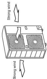
- When using an air conditioner under low outside temperature conditions (Outside temp: -5^ or lower) in COOL mode, prepare a duct or wind shield so that it is not affected by the wind.
-
When installing the unit in an area where snowfalls may be heavy, take steps to prevent the unit from being adversely affected by the fallen or accumulated snow.
-
Either make the foundation higher or install a stand (which is high enough to ensure that the unit will be above the fallen or accumulated snow) and place the unit on it.
- Attach a snow shield (locally procured).
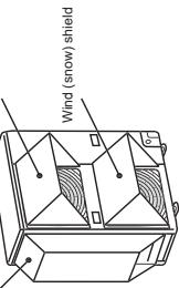
Wind (snow) shield Wind (snow) shield
1) Install the unit so that its discharge port faces the wall of the building.
Keep a distance 500mm or more between the unit and wall surface.
Install the outdoor unit in a location that meets the
obtained.
A well-ventilated location free from obstacles near the air inlets and air outlet
A location that is not exposed to rain or direct sunlight
-
A location that does not increase the operating noise or vibration of the outdoor unit
-
A location that does not produce any drainage problems from discharge water.
from discharged water
Do not install the outdoor unit in the following locations.
- A location with a saline atmosphere (coastal area) or one that is full of sulfide gas (hot-spring area) (Special
maintenance is required.)
-
A location subject to oil, vapor, oily smoke, or corrosive gases.
-
A location in which organic solvent is used
-
A location where high-frequency equipment (including inverter equipment, private power generator, medical
inverter equipment, private power generator, medical equipment, and communication equipment) is used
(Installation in such a location may cause malfunction of the system).
the air conditioner, abnormal control of problems due to noise from such equipment.)
A location in which the discharged air of the outdoor unit is not available for use by the user.
blows against the window of a neighboring house A location where the operating noise of the outdoor unit is
transmitted
-
When the outdoor unit is installed in an elevated position, be sure to secure its feet.
-
A location in which drain water poses any problems.
-
Install the outdoor unit in a location where the discharge
-
Install the outdoor unit in a location where the discharge air is not blocked.
-
When an outdoor unit is installed in a location that is
always exposed to strong winds like a coast or on thehigh stories of a building , secure normal fan operation by
using a duct or wind shield.
When installing the outdoor unit in a location that isconstantly expressed to strong winds such as on the up
Constantly exposed to strong winds such as on the up stairs or rooftop of a building, apply the windproofing
measures referred to in the following examples.
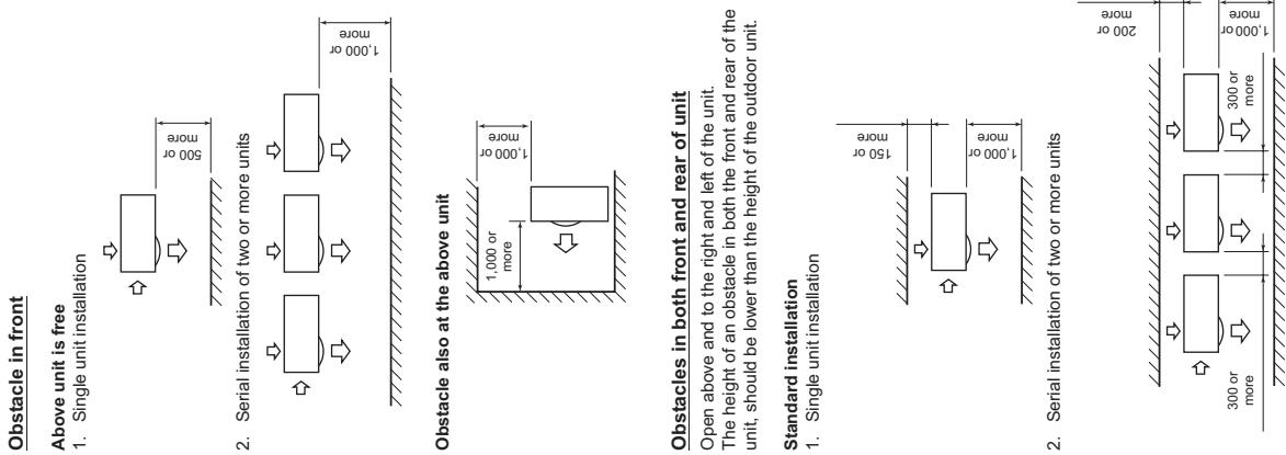
Serial installation in front and rear
Open above and to the right and left of the unit. The height of an obstacle in both the front and rear of the unit should be lower than the height of the outdoor unit.
Standard installation
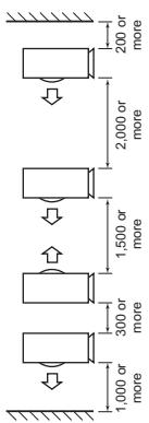
Installation of Outdoor Unit
Before installation, check the strength and horizontalness of the base so that abnormal sounds do not emanate. According to the following base diagram, fix the base firmly with the anchor bolts. (Anchor bolt, nut: M10 x 4 pairs)
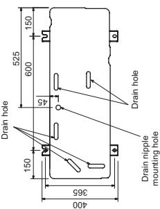
Set the out margin of the anchor bolt to 15mm or less.
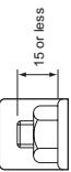
Knockout of Pipe Cover
hole can easily be punched.
After punching out the knockout hole, remove burrs from the hole and then install the supplied protective bush and guard material around the passage hole to protect wires and pipes.
Be sure to attach the pipe covers after pipes have been connected. Cut the slits under the pipe covers to facilitate the installation.
After connecting the pipes, be sure to mount the pipe cover. The pipe cover is easily mounted by cutting off the slit at the lower part of the pipe cover.
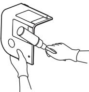
Be sure to wear heavy work gloves while working.
Take off the knockout part of the pipe cover through which pipes or wires will pass through the base plate.
■ Optional Installation Parts (Locally procured)
| Parts name | Q'ty | |
| A | Refrigerant piping Liquid side: Ø9.5 mm Gas side: Ø15.9 mm | One each |
| B | Pipe insulating material (polyethylene foam, 10 mm thick) | 1 |
| C | Putty, PVC tape | One each |
Refrigerant Piping Connection
CAUTION
TAKE NOTE OF THESE 4 IMPORTANT POINTS BELOW FOR PIPING WORK 1. Keep dust and moisture away from inside the connecting
pipes.
2. Tightly connect the connection between pipes and the unit.
-
Evacuate the air in the connecting pipes using a
-
Check for gas leaks at connection points.
a_3^ * = -b - 12b
Piping connection
Liquid side
Outer diameter Thickness Ø9.5 mm 0.8 mm
Gas side Outer diameter Thickness 015.9 mm 1.0 mm
Flaring
- Cut the pipe with a pipe cutter. Be sure to remove burrs that may cause a gas leak.
Insert a flare nut into the pipe, and then flare the pipe. Use the flare nuts supplied with the air conditioner or
those for R410A.
Insert a flare nut into the pipe, and flare the pipe. As the flaring sizes of R410A differ from those of
refrigerant R22, the flare tools newly manufactured for R410A are recommended.
However, the conventional tools can be used by adjusting the projection margin of the copper pipe.
Projection margin in flaring: B (Unit: mm)
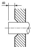
Rigid (Clutch type)
| Outer diam. of copper pipe | R410A tool used | Conventional tool used |
| R410A | 1.0 to 1.5 | |
| 9.5 | 0 to 0.5 | |
| 15.9 |
Flaring diameter size: A (Unit: mm)

| Outer diam. of copper pipe | A+0-0.4 |
| 9.5 | 13.2 |
| 15.9 | 19.7 |
In case of flaring for R410A with the conventional flare
tool, pull the tool out approx. 0.5 mm more than that for R22 to adjust it to the specified flare size.
The copper pipe gauge is useful for adjusting the
projection margin size.
Refrigerant Pipe Length
#
#
| Allowable pipe length (m) | Height difference (Indoor-outdoor H) (m) | |
| Total length L | Indoor unit: Upper | Outdoor unit: Lower |
| 75 | 30 | 30 |
| Pipe diameter (mm) | Number of bent portions | |
| Gas side | Liquid side | 10 or less |
| Ø15.9 | Ø9.5 | |
Simultaneous twin, triple
| System | Model | Allowable pipe length (m) | Height difference (m) | ||||
| Total length • 11 + 12 • 11 + 13 • 11 + 14 Maximum | Distributed pipes • 12 • 13 • 14 Maximum | Distributed pipes • 13 - 12 • 14 - 13 Maximum | Indoor-outdoor H | Indoor-indoor (h) | |||
| Indoor unit: Upper | Outdoor unit: Upper | ||||||
| TWIN | SP110 | 50 | 15 | 10 | 30 | 30 | 0.5 |
| SP140, SP160 | 50 | 15 | 10 | 30 | 30 | 0.5 | |
| TRIPLE | SP160 only | 50 | 15 | 10 | 30 | 30 | 0.5 |
| System | Model | Pipe diameter (mm) | Number of bent portions | |||
| Main pipe | Branching pipe | |||||
| Gas side | Liquid side | Gas side | Liquid side | |||
| TWIN | SP110 | Ø15.9 | Ø9.5 | Ø12.7 | Ø6.4 | 10 or less |
| SP140, SP160 | Ø15.9 | Ø9.5 | Ø15.9 | Ø9.5 | 10 or less | |
| TRIPLE | SP160 only | Ø15.9 | Ø9.5 | Ø12.7 | Ø6.4 | 10 or less |
Figure of Simultaneous twin
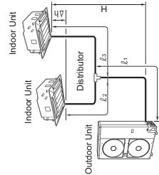
Figure of Single
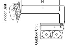
Vacuum pump
Before starting an airtight test, further tighten the spindle valves on the gas side and liquid side. Pressurize the pipe with nitrogen gas charged from the service port to the design pressure (4.15 MPa) to conduc
the airtight test. After the airtight test is completed, evacuate the nitrogen gas.
Air Purge
With respect to the preservation of the terrestrial
environment, adopt ' vacuum pump ' to purge air ( Eair in the connecting pipes) when installing the unit
- Do not discharge the refrigerant gas to the atmosphere to
preserve the terrestrial environment.
- Use a vacuum pump to discharge the air (nitrogen, etc.) that remains in the jet. If air remains, the viscosity may
that remains in the set. If all remains, the capacity may decrease
For the vacuum pump, be sure to use one with a backflow
preventer so that the oil in the pump does not backflow into
the pipe of the air conditioner when the pump stops. (2) If oil in the vacuum pump is put in an air conditioner,
If on in the vacuum pump is put in an air conditioner, including R410A, it may cause trouble with the refrigeration
cycle.)
Compound pressure gauge Pressure gauge -101kPa Gauge manifold valve
(-76 cmHg)
Handle Low Handle High
Charge hose (Keep fully closed)
(For R410A only) Charge hose
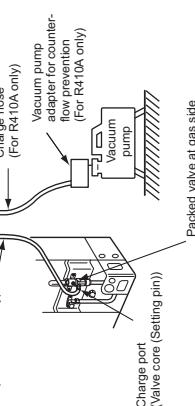
Tighten the valve and caps of the charge port securely.
Use the vacuum pump, vacuum pump adapter, and gauge
manifold correctly referring to the manuals supplied with each tool before using them.
Check that the vacuum pump oil is filled up to the specified line
of the oil gauge. When air is not charged, check again whether the connecting
mechanism is discharged, which again initiates the connecting port of the discharge hose, which has a projection to push the
valve core, is firmly connected to the charge port.
How to open the valve
Open or close the valve.
Liquid side
Open the valve with a 4mm hexagon wrench.
ELECTRICAL WORK
WARNING
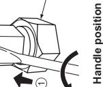
Handle position
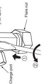
Handle position
Requirement for replenishing refrigerant
Replenish liquid refrigerant.
When gaseous refrigerant is replenished, the refrigera
composition varies, which disables normal operation.
tional with capacity short
installation may cause an elec
m - 1 0 ;
National writing regulations. Capacity shortages of the power circuit or an incomplete installation may cause an electric shock or fire.
CAUTION
Wiring between Indoor Unit and Outdoor Unit
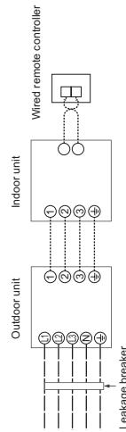
| Valve size | Ø9.5 mm | 33 to 42 N·m (3.3 to 4.2 kgf·m) |
| Ø15.9 mm | 20 to 25 N·m (2.0 to 2.5 kgf·m) | |
| Charge port | 14 to 18 N·m (1.4 to 1.8 kgf·m) | |
| Model (RAV-SP Type) | 110AT8 | 140AT8 | 160AT8 |
| Power supply | 380-415 V 3N~50 Hz | ||
| Maximum running current | 16.4 A | ||
| Recommended field fuse | 20 A | ||
| Power wire* | 5 × 2.5 mm² or more (H07 RN-F or 60245 IEC 66) | ||
| Indoor/outdoor connecting wires* | 4 × 1.5 mm² or more (H07 RN-F or 60245 IEC 66) | ||
Number of wire wire size
Using the specified wires, ensure that the wires are connected, and fix wires securely so that the external
tension to the wires does not affect the connecting part of the terminals.
Incomplete connection or fixation may cause a fire, etc. Be sure to connect the earth wire. (grounding work) Incomplete grounding may lead to electric shock.
Incomplete grounding may lead to electric shock. Do not connect ground wires to gas pipes, water pipes, or other sources.
valve fixing plate and cord clamps stored in the electric parts box.
m - 1 0 ;
- A metal pipe can be installed through the hole for wiring. If the hole size does not fit the wiring pipe to be used, drill the hole again to an appropriate size.
- Be sure to clamp the power wires and indoor/outdoor connecting wires with a banding band along the connecting pipe so that the wires do not touch the compressor or discharge pipe. (The compressor and the discharge pipe become hot.) Furthermore, be sure to secure these wires with the pipe valve fixing plate and cord clamps stored in the electric parts box.
Wrong wiring may cause a burn-out of some electrical
parts.
Be sure to use the cord clamps attached to the product.
Do not damage or scratch the conductive core or inner insulator of the power and inter connecting wires when
Insulator of the power and inter-connecting wires when sealing them.
peeling arelem: Use the power and Inter-connecting wires with specified properties.
The dashed lines show on-site wiring.
- Connect the indoor/outdoor connecting wires to the identical terminal number. Incorrect connection may cause a failure.
For the air conditioner, connect a power wire with the following specifications.
How to wire
- Connect the connecting wire to the terminal as identified with their respective numbers on the terminal block of the indoor and outdoor units. H07 RN-F or 60245 IEC 66 (1.5 mm² or more)
- When connecting the connecting wire to the outdoor unit
180^
For details on the remote controller wiring/installation, refer to the Installation Manual enclosed with the remote controller.
Single system
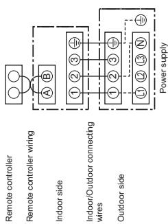
An installation line of this air
An installation fuse must be used for the power supply
line of this air conditioner. Incorrect/incomplete wiring may lead to an electrical fire.
or smoke.
Prepare an exclusive power supply for the air conditioner.
This product can be connected to the mains power. Fixed-line connections:
A switch that disconnects all poles and has a contact
separation of at least 3mm must be incorporated in the
fixed wiring.
Simultaneous triple system (SP160 only)
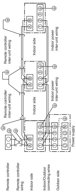
- Use 2-core shield wire (MVVS 0.5 to 2.0 mm^2 or more) for the remote controller wiring in the simultaneous twin and
simultaneous triple systems to prevent noise problems. Be sure to connect both ends of the shield
EARTHING
Connect the earth line properly following applicable technical standards.
Connecting the earth line is essential to preventing electric shock and to reducing noise and electrical charges on the outdoor unit surface due to the high-frequency wave generated by the frequency converter (inverter) in the outdoor unit. If you touch the charged outdoor unit without an earth line, you may experience an electric shock.
FINISHING
After the refrigerant pipe, inter-unit wires, and drain pipe have been connected, cover them with finishing tape and clamp them to the wall with off-the-shelf support brackets or their equivalent. Keep the power wires and indoor/outdoor connecting wires off the valve on the gas side or pipes that have no heat insulator.
10 TEST RUN
-
Turn on the leakage breaker at least 12 hours before starting a test run to protect the compressor during startup. To protect the compressor, power is supplied from the 380-415 VAC input to the unit to preheat the compressor.
-
Check the following before starting a test run:
-
That all pipes are connected securely without leaks.
-
That the valve is open.
If the compressor is operated with the valve closed, the outdoor unit will become overpressurized, which may damage the compressor or other components.
If there is a leak at a connection, air can be sucked in and the internal pressure further increases, which may cause a burst or injury. -
Operate the air conditioner in the correct procedure as specified in the Owner's Manual.
ANNUAL MAINTENANCE
ANNUAL MAINTENANCE For an air conditioning system that is operated on a regular basis, cleaning and maintenance of the indoor/outdoor units are strongly recommended.
As a general rule, if an indoor unit is operated for about 8 hours daily, the indoor/outdoor units will need to be cleaned at least once every 3 months. This cleaning and maintenance should be carried out by a qualified service person. Failure to clean the indoor/outdoor units regularly will result in poor performance, icing, water leaking and even compressor failure.
AIR CONDITIONER OPERATING CONDITIONS
| For proper performance, operate the air conditioner under the following temperature co | ||
| Cooling operation | Dry bulb temp. | -15°C to 46°C |
| Heating operation | Wet bulb temp. | -20°C to 15°C |
If air conditioner is used outside of the above conditions, safety protection may work.
| Reference outside diameter (mm) | Wall thickness (mm) |
| ∅9.5 | 0.8 |
| ∅15.9 | 1.0 |
| ∅19.0 | 1.0 |
14 TROUBLESHOOTING
You can perform fault diagnosis of the outdoor unit with the LEDs on the P.C. board of the outdoor unit in addition to using the check codes displayed on the wired remote controller of the indoor unit. Use the LEDs and check codes for various checks. Details of the check codes displayed on the wired remote controller of the indoor unit are described in the Installation Manual of the indoor unit.
Verifying current abnormal status
- Check that DIP switch SW803 is set to OFF.
-
Let down the status of LF5900 to LF5901 (F
-
Press SW800 for at least 1 second. The LED status changes
-
Check the code whose display mode 1 equals the LED states jotted down and display mode 2 equals the current flashing status of LED800 to LED804 from the following table to identify the cause.
verifying an abnormal state in the past although the abnormal state no longer occurs 1.2.3.1.1 (BIPolar, 5000 s, ON)
- Set bit 1 of DIP switch SW003 to ON.
-
Jog down the states of LED800 to LED804. (Display mode 1)
-
Press SW800 for at least 1 second. The LED status changes to display mode 2.
-
Find a row/row shows display mode 1, and the LED status is turned down and display mode 2 equals the current flashing
-
Find an error whose display mode 1 equals the LED state, just down and states of LED800 to LED804 from the following table to identify the error.
-
An outside air temperature (TO) sensor error can be checked only while it occurs.
| No. | Cause | Display mode 1 | Display mode 2 | ||||||||
| D800 | D801 | D802 | D803 | D804 | D800 | D801 | D802 | D803 | D804 | ||
| 1 | Normal | ● | ● | ● | ● | ● | ● | ● | ● | ● | ● |
| 2 | Discharge (TD) sensor error | ○ | ○ | ● | ● | ○ | ● | ● | ◎ | ● | ● |
| 3 | Heat exchanger (TE) sensor error | ○ | ○ | ● | ● | ○ | ● | ◎ | ◎ | ● | ● |
| 4 | Heat exchanger (TL) sensor error | ○ | ○ | ● | ● | ○ | ◎ | ◎ | ◎ | ● | ● |
| 5 | Outside air temperature (TO) sensor error | ○ | ○ | ● | ● | ○ | ● | ● | ● | ◎ | ● |
| 6 | Suction (TS) sensor error | ○ | ○ | ● | ● | ○ | ● | ● | ◎ | ◎ | ● |
| 7 | Heat sink (TH) sensor error | ○ | ○ | ● | ● | ○ | ◎ | ● | ◎ | ◎ | ● |
| 8 | Outdoor temperature sensor (TE/TS) connection error | ○ | ○ | ● | ● | ○ | ◎ | ◎ | ◎ | ◎ | ● |
| 9 | Outdoor EEPROM error | ○ | ○ | ● | ● | ○ | ◎ | ◎ | ◎ | ◎ | ◎ |
| 10 | Compressor breakdown | ● | ● | ○ | ● | ○ | ◎ | ● | ● | ● | ● |
| 11 | Compressor lock | ● | ● | ○ | ● | ○ | ● | ◎ | ● | ● | ● |
| 12 | Current detection circuit error | ● | ● | ○ | ● | ○ | ◎ | ◎ | ● | ● | ● |
| 13 | Thermostat for compressor activated | ● | ● | ○ | ● | ○ | ● | ● | ◎ | ● | ● |
| 14 | Model data not set (on the service P.C. board) | ● | ○ | ○ | ● | ○ | ● | ◎ | ● | ◎ | ● |
| 15 | MCU-MCU communication error | ● | ○ | ○ | ● | ○ | ◎ | ● | ◎ | ◎ | ◎ |
| 16 | Discharge temperature error | ○ | ○ | ○ | ● | ○ | ◎ | ◎ | ● | ● | ● |
| 17 | Abnormal power (open phase detected or abnormal voltage) | ○ | ○ | ○ | ● | ○ | ◎ | ● | ◎ | ● | ● |
| 18 | Heat sink overheat | ○ | ○ | ○ | ● | ○ | ◎ | ◎ | ◎ | ● | ● |
| 19 | Gas leak detected | ○ | ○ | ○ | ● | ○ | ◎ | ◎ | ◎ | ◎ | ● |
| 20 | 4-way valve reverse error | ○ | ○ | ○ | ● | ○ | ◎ | ◎ | ● | ● | ◎ |
| 21 | High pressure release operation | ○ | ○ | ○ | ● | ○ | ● | ● | ◎ | ● | ◎ |
| 22 | Outdoor fan motor error | ○ | ○ | ○ | ● | ○ | ● | ◎ | ◎ | ● | ◎ |
| 23 | Compressor driver short-circuit protection | ○ | ○ | ○ | ● | ○ | ● | ◎ | ● | ◎ | ◎ |
| 24 | Position detection circuit error in one-line display | ○ | ○ | ○ | ● | ○ | ◎ | ● | ◎ | ◎ | ◎ |
| 25 | High pressure SW error | ○ | ○ | ○ | ● | ○ | ● | ● | ◎ | ● | ● |
(●: OFF ○: ON ©: Flashing)
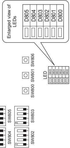
* The LEDs and DIP switches are
located on the lower left board of the outdoor unit.
15 APPENDIX
Work instructions
The existing R22 and R407C piping can be reused for our digital inverter R410A product installations. Check if the oil is judged to be clearly different from
WARNING - The refrigerator oil is copper rust green in color:
There is the possibility that moisture has mixed with oil and rust has been generated inside the pin.
existing pipes and confirming the reliability of the pipe There is discolored oil, a large quantity of residue
strength are conventionally referred to the local site. bad smell. If the specified conditions can be cleared, it is possible A large quantity of shiny metal dust or other wear
to update existing R22 and R407C pipes to those for residue can be seen in the refrigerant oil. D140A model. 7. When the air conditioner has a history of the comp
When added on, a large quantity of residue, or metal dust, or other wear residue or mixture of for
Basic conditions needed to reuse existing pipes matter is observed, trouble will occur. Check and choose the presence of three conditions in the
Refrigerant piping works. conditoner are repeated such as when leased etc.
-
Dry (There is no moisture inside of the pipes.) 3. If this type of flonger oil of the existing air compressor is not available, it is other than the following oil (Mineral oil), Suniso, R
-
Tight (There are no refrigerant leaks.) S, MS (Synthetic oil), alkyl benzene (HAB, Barrel-free ester series, B/F) only of other series.
Restrictions for use of existing pipes The winding-insulation of the compressor may
NOTE
The above descriptions are results have been confirm
our company and represent our views on our airconditioners , but do not guarantee the use of the existing
pipes of air conditioners that have adopted R410A in other
Company Name:
Branching pipe for simultaneous operation system
In the concomitant twin system, when TCGMBA has specified that branching pipe is to be used, it can be
reused.
RBC-TWP30E2, RBC-TWP50E2, RBC-TRP100E
On the existing air conditioner for simultaneous operation system (twin, triple system), there are cases of branch
pipes being used that have insufficient compressive
In such case, please change the piping to a branch pipe.
for R410A.
Curing of pipes
When removing and opening the indoor or outdoor unit
long time, cure the pipes as follows: Otherwise, gut may be generated when moisture or
foreign matter due to condensation enters the pipes The extent of heat transfer by heating and gas
The fact cannot be removed by cleaning, and how this are necessary.
| Placement location | Term | Curing manner |
| Outdoors | 1 month or more | Pinching |
| Less than 1 month | Pinching or taping | |
| Indoors | Every time |
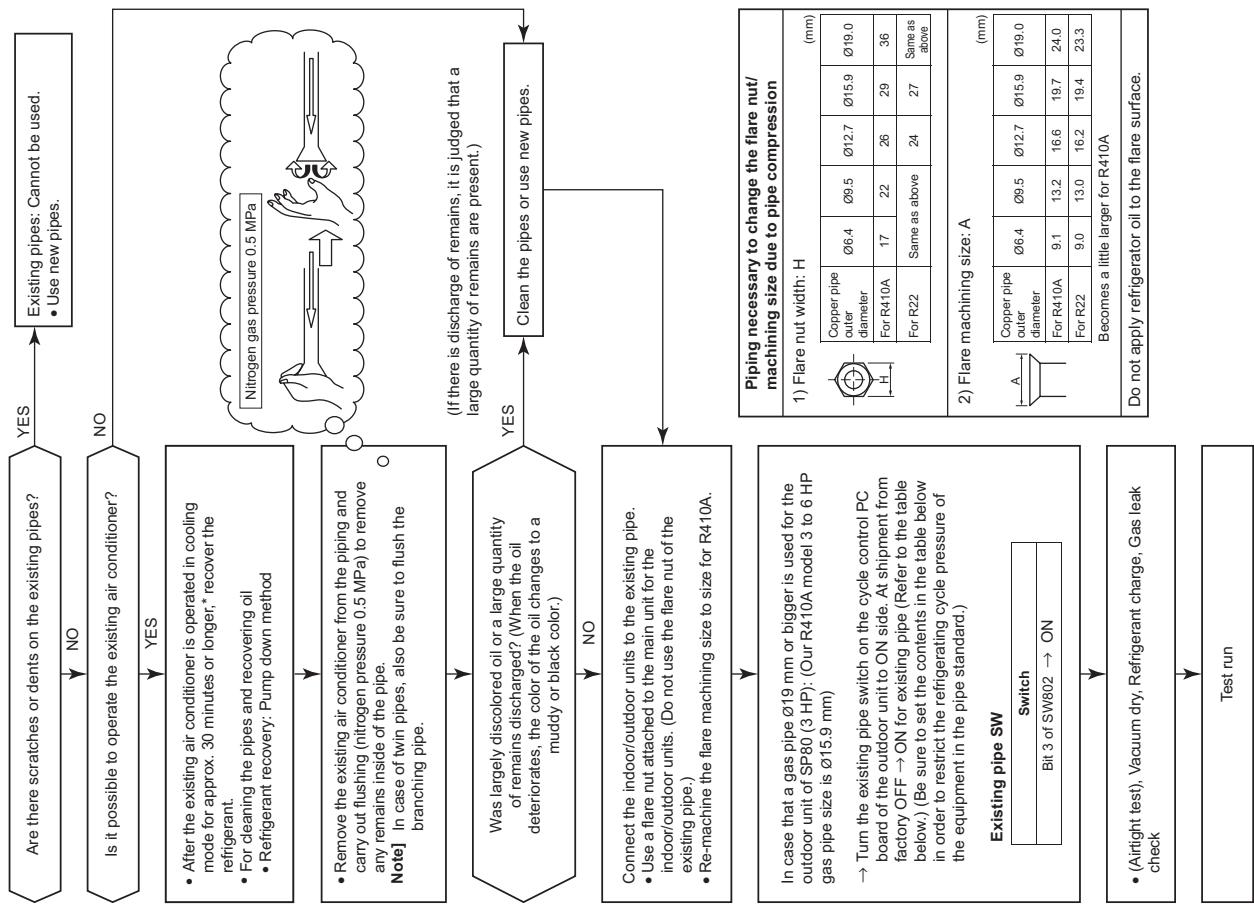
| This product contains fluorinated greenhouse gases covered by the Kyoto Protocol | |
| Chemical Name of Gas | R410A |
| Global Warming Potential (GWP) of Gas | 1975 |

IMPORTANT INFORMATION AND WARNING:
READ BEFORE INSTALLING THE UNIT. KEEP IN A SAFE PLACE. THE INFORMATION IN THIS BOOKLET IS NEEDED FOR END OF LIFE, DISPOSAL OR REUSE OF THE UNIT. We are very sensitive to environment and welcome the 2002/96/EC Directive WEEE (Waste Electrical and Electronic Equipment). This product is compliant with EU directive 2002/96/EC. It must be collected separately after its use is completed, and cannot be disposed of as unsorted municipal waste.
The objectives of EU directive 2002/96/EC are to tackle the fast increasing waste stream of electrical and electronic equipment, increase recycling of electric & electronic equipment ("EEE"), and to limit the total quantity of waste EEE ("WEEE") going to final disposal. The crossed-out wheeled bin symbol that is affixed to the product means that this product falls under the Directive. The user is responsible for returning the product to the appropriate collection facility, as specified by your municipality or the distributor. In case of a new product installation, it may be possible to have the distributor pick up old WEEE directly. The producer, importer and distributor of the product are responsible for collection and treatment of waste, either directly or through a
collective system. The list of our distributor in each country is shown below. In case of a violation of the Directive, sanctions are set in each country. We are in general following the "CECED interpretation," and consider the WEEE applicable to Portable units, Dehumidifiers, WRACs (Window Room Air Conditioners), Split Systems up to 12kW plug in refrigerators and freezers. Nevertheless, there may be differences among member state laws. In case country laws exclude some products from WEEE scope, country law must be followed, and WEEE obligations do not have to be followed for products that fall out of country low scope. This directive does not apply to products sold outside European Community. In case the product is sold outside the EU, WEEE obligations do not have to be followed, while compliance with local regulations must be ensured. For additional information, please contact the municipal facility, the shop/dealer/installer that sold the product, or the producer.
| Country Name of Company responsible for WEEE. | ||||
| Austria | AIRCOND, Klimaanlagen Handelsgesellschaft m.b.H Petegsgasse 45, A-8010 Graz Austria | Ireland | GT Phelan Unit 30 Southern Cross Business Park Bray Co Wicklow, Ireland | UK Toshiba Carrier UK Ltd Porsham Close, Belliver Ind. Est. Plymouth, Devon, PL6 7DB |
| Italy | Carrier SpA Via R. Sanzio, 9 20058 Villasanta (Milano), Italy | |||
| Belgium | DOLPHIN NV, Fotogra fil aan 12, B-2610, Antwerpen Belgium | Latvia | Carrier OY Linnavuoretie 28A 00950 Helsinki, Finland | Czech AIRCOND, Klimaanlagen Republic Handelsgesellschaft m.b.H Petersgasse 45, A-8010 Graz Austria |
| Cyprus | Carrier Hellas Airconditioning S.A.-4g Andersen street- 11525 Athens, Greece | Lithuania | Carrier OY Linnavuoretie 28A 00950 Helsinki, Finland | Slovakia AIRCOND, Klimaanlagen Handelsgesellschaft m.b.H Petersgasse 45, A-8010 Graz Austria |
| Denmark | GIDEX A/S, Korshøj 10, 3600 Frederikssund, Denmark | Luxembourg | DOLPHIN NV Fotogra fil aan 12, B-2610, Antwerpen Belgium | |
| Estonia | Carrier OY Linnauvouretnie 28A 00950 Helsinki, Finland | Malta | CUTRICO Services Ltd, Cutrico Building Psala Street, Sta Venea HMR 16, Malta | Slovenia AIRCOND, Klimaanlagen Handelsgesellschaft m.b.H, Petersgasse 45, A-8010 Graz Austria |
| Finland | Carrier OY Linnauvouuretnie 28A 00950 Helsinki, Finland | Norway | Carrier AB - P.O.BOX 8946- Arods Industrivag 32. S-402 73 Gothenburg, Sweden | Spain Carrier Espana S.L. - Paseo Castellana 36-38, 28046 Madrid |
| France | Carrier S.A. Route de Thil BP 49 01122 Montiujel Cedex France | Poland | Carrier Polska Sp. Z.o.o. Postepu 14 02-676 Warsaw Poland | Sweden Carrier AB - P.O.BOX 8946- Arods Industrivag 32. S-402 73 Gothenburg |
| Germany | Carrier GmbH & Co. KG Edisonstrasse 2 85716 Unterschleissheim | Portugal | Carrier Portugal - AR Condicionado LDA Avenida do Forte, Nr. 3 Edito cio Suecia I,Piso 1 Camaxide 2794-043 Portugal | Hungary AIRCOND, Klimaanlagen Handelsgesellschaft m.b.H Petersgasse 45, A-8010 Graz Austria |
| Greece | Carrier Hellas Airconditioning S.A.-4g Andersen street- 11525 Athens, Greece | |||
| Holland | INTERCOOL Technologies BV Nikkelstraat 39, Postbus 76 2980 AB Ridderkerk Netherlands | |||
The manufacturer reserves the right to change any product specifications without notice.
Declaration of Conformity
Toshiba Carrier Corporation 336 Tadehara, Fuji-shi, Shizuoka-ken 416-8521 JAPAN
Nick Ball
Toshiba EMEA Engineering Director
Techbi Coerier UK Ltd.
Toshiba Carrier Borsham Close
FOMNCHGSE,BOVIER Industrial Estate, PLYMOUTHDevon,PL6ZDB
United Kingdom
Hereby declares that the machinery described below:
Generic Denomination: Air Conditioner
RAV-SP1104AT8-E, RAV-SP1104AT8Z-E, RAV-SP1104AT8ZG-E,
RAV-SP1404AT8-E, RAV-SP1404AT8Z-E, RAV-SP1404AT8ZG-E,
RAV-SP1604AT8-E, RAV-SP1604AT8Z-E, RAV-SP1604AT8ZG-E,
RAV-SP1104AT8-TR RAV-SP1104AT8Z-TR RAV-SP1104AT8ZG-TR
RAV-SP1404AT8-TR, RAV-SP1404AT8Z-TR, RAV-SP1404AT8ZG-TR.
RAV-SP1604AT8-TR, RAV-SP1604AT8Z-TR Commercial name: Super Digital Inverter Series Air Conditioner
Complies with the provisions of the "Machinery" Directive (Directive 2006/42/EC) and the regulations transposing
into national law
Complies with the provisions of the following harmonized standard:
EN 378-2: 2008
Note: This declaration becomes manufacturer's consent.
14. DETACHMENTS
14-1. Outdoor Unit
RAV-SP1104AT8 (7), RAV-SP1404AT8 (7), RAV-SP1604AT8 (7) series
| No. | Part name | Procedure | Remarks |
| ① | Common procedure | WARNING Stop operation of the air conditioner and turn off breaker switch. | Service panel Top plate |
| CAUTION Ensure wearing of gloves when performing any work in order to avoid injury from parts, etc. | |||
| 1. Detachment 1) Remove the service panel. (Hexagonal screws Ø4 x 10, 2 pcs.) • Remove the screws and then pull service panel downward to remove. 2) Remove the power supply cable and the indoor/outdoor connecting wire from the cord clamp and the terminal. 3) Remove the top plate. (Hexagonal screws Ø4 x 10, 5 pcs.) | |||
| 2. Attachment 1) Attach the top plate. (Hexagonal screws Ø4 x 10, 5 pcs.) 2) Connect the power supply cable and the indoor/outdoor connecting wire to the terminal and then fix with the cord clamp. | |||
| CAUTION The power supply cable and the indoor/outdoor connecting wire must be affixed along the crossover pipe using a commercially available bundling band so that they do not make contact with the compressor, gas valve, gas pipe and discharge pipe. 3) Attach the front panel. (Hexagonal screws Ø4 x10, 2 pcs.) | |||
| ② | Discharge port cabinet | 1. Detachment 1) Carry out the operation in 1. of ① above. 2) Remove the screws fixing the inverter assembly, the discharge port cabinet and the partition board. (ST1T Ø4 × 8, 4 pcs.) 3) Remove the screws for the discharge port cabinet and the bottom plate. (Hexagonal screw Ø4 × 10, 2 pcs.) 4) Remove screw for the discharge port cabinet and heat exchanger. (ST1T Ø4 × 8, 1 pc.) 5) Remove screw for the discharge port cabinet and the motor base. (ST1T Ø4 × 8, 2 pcs.) 6) Remove screws for the discharge port cabinet and the fin guard. (Hexagonal screw Ø4 × 10, 2 pcs.) | Heat exchanger Motor base Discharge portcabinet Bottom plate |
| 2. Attachment 1) Attach the discharge port cabinet and end board of heat exchanger and fix with a screw. (ST1T Ø4 × 8, 1 pc.) 2) Mount other removed screws into original positions. | |||
| ③ | Side cabinet | 1. Detachment 1) Carry out the operation in 1. of ① above. 2) Remove the screws fixing the inverter assembly and the side cabinet. (ST1T Ø4 × 10, 3 pcs.) 3) Remove the screws for the side cabinet and the valve fixing plate. (ST1T Ø4 × 10, 2 pcs.) 4) Remove screw for the side cabinet and piping panel (rear). (Hexagonal screw Ø4 × 10, 2 pcs.) 5) Remove screw for the side cabinet and the bottom plate. (Hexagonal screw Ø4 × 10, 1 pc.) 6) Remove screws for the side cabinet, heat exchanger and the fin guard. (Hexagonal screw Ø4 × 10, 5 pcs.) | Discharge port cabinet Inverter ass'y Valve fixing plate Valve fixing plate Valve fixing plate Valve fixing plate Valve fixing plate |
| ④ | Inverter assembly | 1. Detachment 1) Carry out the operation in 1. of ①, 1. of ③ above. 2) Remove the connectors connected to the Fan IPDU board, the connector connected to other components from the control board (Interface board). CN600: TS sensor (3P: White, tube: Gray) CN601: TE sensor (2P: White, tube: Blue) CN602: TO sensor (2P: Yellow, tube: Black) CN603: TD sensor (3P: White, tube: Red) CN604: TL sensor (2P: White, tube: White) CN609: Case thermo. (2P: Blue) CN690: High poressure switch (3P: Green) CN700: 4-way coil (3P: Yellow) CN710: PMV coil (6P: White) ·Fan IPDU board CN700: Outdoors lower fan motor (3P: Blue) CN750: Outdoors upper fan motor (3P: White) Cut the banding band and remove connector connected from fan motor to fan motor relay board. *Remove connectors after unlocking housing section 3) Remove the screw (1 position) fixing the discharge port cabinet. 4) Cut bundling band fixing various lead lines to inverter assembly. 5) Remove sound-insulation plate (upper). 6) Remove terminal cover of compressor and remove compressor lead. 7) Pull up the inverter assembly at upper side to remove hook of partition plate (rear left part). 2. Attachment 1) Mount the inverter assembly on the partition plate. CAUTION When mounting the inverter assembly on the partitioning plate, ensure proper mounting of the hook (rear left part) with partitioning plate. 2) Mount the individual components in the opposite procedure to that during detachment. | Cut the banding band Fan-IPDU board Remove the fan motor lead wire from the cord clamp. Discharge port cabinet Outthe banding band Remove the fan motor lead wire from the cord clamp. Sound-insulation plate (upper) Sound-insulation plate (rolling out) Partition plate |
| Compressor lead Case thermostat | Inverter assembly Hook | ||
| ⑤ | Interface board (Control board) MCC-1599 | 1. Detachment 1) Carry out the operation in 1. of ①, and 1. of ③ above. 2) Remove lead wires and connectors to other components from the interface board (control board). CN01: Indoor/Outdoor connection terminal (5P: White) CN02: Power relay (3P: Red) CN600: TS sensor (3P: White, tube: Gray) CN601: TE sensor (2P: Green, tube: Blue) CN602: TO sensor (2P: Yellow, tube: Black) CN603: TD sensor (3P: White, tube: Red) CN604: TL sensor (2P: White, tube: White) CN608: Connection with noise filter board (2P: White) CN609: Case thermo. (2P:Blue) CN690: High pressure switch (3P: Green) CN700: 4-way coil (3P: Yellow) CN708: Magnet switch (3P: Blue) CN710: PMV coil (6P: White) CN802: Connection with Fan IPDU board (5P: white) * Remove connectors after unlocking housing section 3) Remove the claws of the supports (4 positions) fixing the board and remove the interface board (Control board). 2. Attachment 1) Mount the interface board (Control board). 2) Mount the individual components in the opposite procedure to that during detachment. | Interface board (Control board) Support (4 positions) Statue of control board when removed |
| ⑥ | Fan-IPDU board MCC-1597 | 1. Detachment 1) Carry out the operation in 1. of ①, and 1. of ③ above. 2) Remove lead wires and connectors to other components from the Fan-IPDU board. CN500: Connection between reactor and noise filter board (7P, Red) CN502: Compressor IPDU board (3P, White) CN504: Interface board (5P, Blue) CN505: Compressor IPDU board (5P, Red) CN602: Noise filter board (2P, Black) CN700: Outdoors lower fan motor (3P, Blue) CN750: Outdoors upper fan motor (3P, White) * Connectors should be removed after unlocking the housing section. 3) Remove screw fixing the earth wire. 4) Remove the claw of the support (4 positions) fixing the board and the screw (5 positions) fixing the heat sink and then remove the Fan- IPDU board. 2. Attachment 1) Mount Fan-IPDU board 2) Mount components in the opposite method to that when removing. | FAN-IPDU board Screw Earth wire Support (2 positions) Heat sink State of Fan-IPDU board when removed |
| ⑦ | Noise filter boardMCC-1600 | 1. Detachment1) Perform the operation in 1. of ①,1. of ④,1.-2 of ⑤ and 1.-2 of ⑥.2) Remove the screws (3 positions) fixing the inverter assembly (front). Then slide the inverter assembly (front) upwardly and remove.3) Remove the lead wires connector to other components from the noise filter board.CN05: Power supply terminal block (red)CN06: Power supply terminal block (White)CN07: Power supply terminal block (Black)CN08: Power supply terminal block (Gray)CN09: Connection to earth (Brown)CN10: Posister (Red)CN16: Relay (Red)CN17: Compressor IPDU board (White)CN18: Relay (Black)CN19: Relay (Gray)CN20: Power supply terminal block (White)CN23: Fan-IPDU board (5P, Red)CN50: Interface board (2P, White)CN51: Fan-IPDU board (2P, Back)* Connectors should be removed after unlocking the housing section.4) Remove the claw of the support (2 positions) and the screw (2 positions) fixing the base and then remove the noise filter base. | Fan-IPDU board Interface board Inverter assembly (front) Inverter assembly (front) Support (2 positions) Screws (2 positions) State of noize filter board when removed |
| Using the hook, it is possible to temporarily suspend the inverter assembly (front). | |||
| ⑧ | Compressor IPDU board MCC-1596 | 1. Detachment 1) Carry out the operation in 1. of ①, 1. of ④, 1. of ⑤, 1. of ⑥ and 1. of ⑦. 2) Remove the screw (4 positions) fixing the inverter assembly (IPDU). 3) Remove the lead wire and connector to other components from the compressor IPDU board. CN04: Posister (Red) CN09: Power supply terminal block (Yellow) CN10: Power supply terminal block (Yellow) CN11: Relay (Red) CN12: Noise filter board (White) CN13: Relay (Black) CN101: FAN-IPDU board (3P, White) CN211: Compressor (Red) CN212: Compressor (White) CN213: Compressor (Black) CN851: FAN-IPDU board (5P, Red) * Connectors should be removed after unlocking the housing section. 4) Slide and remove the inverter assembly (IPDU). 5) Remove the screws (4 positions) fixing the heat sink and the screws (3 positions) fixing the compressor IPDU board and then remove the compressor IPDU board. 2. Attachment 1) Mount compressor IPDU board. 2) Mount components in the opposite method to that when removing. | Inverter assembly (front) Screws (4 positions) Compressor IPDU board Screws (3 positions) State of compressor IPDU board when removed |
| No | Part name | Procedure | Part name |
| ⑨. | Fan motor | 1) Carry out works of item 1 of ① and work of ②. 2) Remove the flange nut fixing the fan motor and the propeller fan. • The flange nut is loosened by turning it clockwise. (When tightening it, turn it counterclockwise.) 3) Remove the propeller fan. 4) Remove the connector for the fan motor from the inverter. (Remove the ferrite core of the lower fan motor because it is used.) 5) Remove the fan motor lead from the fan motor lead fixed rubber of the penetrated part of the partition board. 6) Remove the fixing screws (4 pieces each) while supporting the fan motor so that it does not fall down. * Cautions for assembling of fan motor • Tighten the flange nut with 4.95N·m (50kgf·cm). • Adjust length of the fan motor lead wire at the fan motor lead fixed rubber so that the fan motor lead is not slack-ened; otherwise the fan motor lead may come to contact with the propeller fan. Attach the fan motor lead fixed rubber to the partition board so that the projection is set at the refrigerating cycle side. • Be sure so that the rector body does not contact with the fan motor lead. • Be sure to bundle the removed bundling band with the bundling band on the market. • Necessarily attach the ferrite core of the lower fan motor again. (Fix it with bundling band on the market.) | Propeller fan Loosened by turning clockwise Flange nut Propeller fan Fan motor Connector of upper fan motor Projection/Refrigerating cycle side Fan motor lead fixed rubber Ferrite core Connector of lower fan motor Fan motor lead fixed rubber Projection/Refrigerating cycle side |
| REQUIREMENT Be sure to fix the fan motor lead to the motor base using the metal band of the motor base so that the fan motor lead does not come to contact with the propeller fan. | |||
| Fan motor Fan motor Fan motor lead Ferrite core Connector of lower, fan motor Fan motor lead fixed rubber Projection/Refrigerating cycle side | |||
| No. | Part name | Procedure | Remarks |
| 10 | Compressor Compressor lead | 1. Removal of defective compressor 1) Recover the refrigerant gas. 2) Carry out work of item 1 of ①, 1 of ③ and 1 of ⑦. 3) Remove the piping panel (Front). Remove the piping panel (Front) and screws of the bottom plate. (Hexagonal screw Φ4 × 10, 2 pcs.) Remove screw of the piping panel (Front) and the piping panel (Rear). (Hexagonal screw Φ4 × 10, 1 pc.) 4) Remove the piping panel (Rear). Remove the piping panel (Rear) and screws of the bottom plate. (Hexagonal screw Φ4 × 10, 2 pcs.) 5) Remove the sound-insulation plate. (Upper, rolling in, rolling out) 6) Remove the terminal cover of the compressor and then remove the compressor lead and the compressor case thermo. 7) Remove TD sensor which is fixed to the discharge pipe. 8) Remove the compressor lead. Control P.C. board U:CN211 Red V:CN212 White W:CN213 Black 9) Remove ferrite core from compressor lead. 10) Using a burner, remove the discharge pipe and the suction pipe which are connected to the compressor. | Piping panel (Front) Piping panel (Rear) Pipe cover Bundling band (For thermal proof) TD sensor Compressor lead Ferrite core Remove (Discharge pipe) Remove (Suction pipe) Compressor nuts (3 pcs.) |
| 警告 In case of removing the piping by broiling the welded part with a burner, if there is oil in the pipe, it may burst into flames at the moment that wax melted, so take sufficient care. | |||
| CAUTION Note so that the flame does not catch the 4-way valve and PMV. (A malfunction may be caused.) 11) Pull off the discharge pipe and the suction pipe of the refrigerating cycle upward. 12) Remove the compressor nuts which fix the compressor to the bottom plate. (3 pcs.) 13) Pull out the compressor toward you. | |||
| CAUTION As weight of the compressor is 20kg or more, handle it by 2 workers. | |||
| 10 | Compressor Compressor lead (Continued) | 2. Mounting of compressor 1) Mount the compressor in the reverse procedure for removal. | Wrap the ferrite core with the compressor lead wire for 1 time. Compressor lead Ferrite core 0 to 50 (Compressor lead positioning standard) Put the end of sound-insulation plate (rolling out) on the other end at this position. Suction pipe Header, pipe Discharge pipe Pass through sound-insulation plate (rolling in) between compressor and discharge pipe, suction pipe and then put the end of sound-insulation plate on the other end at this position. There should be no clearance between sound-insulation plate (upper) and sound-insulation plate (lower) Sound-insulation plate (upper) Cultural rivet Sound-insulation plate (rolling out) Insert one side under cultural rivet. |
| 3. Vacuuming 1) Connect the vacuum pump to the charge port and the check joint of the gas pipe valve and then drive the vacuum pump. 2) Carry out vacuuming until the vacuum low pressure gauge indicates 1 (mmHg). | |||
| NOTE Before vacuuming, open PMV fully. If PMV is closed, vacuum may be impossible between liquid pipe valve and PMV of the outdoor unit. | |||
| Forced full-opening method of PMV • Turn on the leakage breaker. • Turn on 1 and 3 of Dip switch SW804 on the control P.C. board of the outdoor unit. • Keep pushing SW801 on the control P.C. board of the outdoor unit for 1 second or more. • After pushing SW801 for 1 second or more, turn off the leakage breaker within 2 minutes. | |||
| 4. Refrigerant charge 1) Add the refrigerant amount determined by the pipe length from the charge port of the valve. | |||
| 11 | PMV coil | 1. Detachment 1) Carry out work of item 1 of ①. 2) Turn the coil while pulling upward and then remove the coil from the PMV main unit. 2. Attachment 1) Surely match the positioning projection of the coil with the concave part of PMV main unit and then fix it. | Concave part PMV main unit Positioning projection PMV coil |
| 12 | Fan guard | 1. Detachment 1) Carry out works of item 1 of ① and 1 of ②. REQUIREMENT To prevent scratch on the product, carry out the work on cardboard, cloth, etc. 2) Remove the discharge port cabinet and then put on it so that the fan guard side directs downward. 3) Remove the hooking claws (8 positions) of the fan guard. 2. Attachment 1) Push the hooking claws (8 positions) with hands from the front side to fix the claws. REQUIREMENT Check that all the hooking claws are fixed at the specified positions. | Fan guard Bell mouth Discharge port cabinet Hooking claw |
15. EXPLODED VIEWS AND PARTS LIST
Outdoor Unit
RAV-SP1104AT8-E, RAV-SP1104AT8Z-E, RAV-SP1104AT8ZG-E
RAV-SP1104AT8-TR, RAV-SP1104AT8Z-TR, RAV-SP1104AT8ZG-TR
RAV-SP1104AT7, RAV-SP1104AT7Z, RAV-SP1104AT7ZG

| Location No. | Part No. | Description | Model name RAV-SP | ||
| 1104AT8-E 1104AT8-TR 1104AT7 | 1104AT8Z-E 1104AT8Z-TR 1104AT7Z | 1104AT8ZG-E 1104AT8ZG-TR 1104AT7ZG | |||
| 1 | 43019904 | Holder, Sensor | 3 | 3 | 3 |
| 2 | 43032441 | Nipple, Drain | 1 | 1 | 1 |
| 3 | 43047246 | Bonnet, 3/8 IN | 1 | 1 | 1 |
| 4 | 43047669 | Nut, Flange | 2 | ||
| 5 | 43049739 | Cushion, Rubber | 3 | 3 | 3 |
| 6 | 4304C703 | Compressor, DA422A3F-27M | 1 | 1 | 1 |
| 7 | 43050407 | Thermostat, Bimetal | 1 | 1 | 1 |
| 8 | 43060029 | Filter, Noise | 1 | 1 | 1 |
| 9 | 43063317 | Holder, Thermostat | 1 | 1 | 1 |
| 10 | 43197164 | Nut, Flange | 2 | 2 | |
| 11 | 43197174 | Nut, Comp. | 3 | 3 | |
| 12 | 43097212 | Nut, Comp. | 3 | ||
| 13 | 43100437 | Panel, Front, Piping | 1 | 1 | 1 |
| 14 | 43100438 | Panel, Back, Piping | 1 | 1 | 1 |
| 15 | 43100439 | Panel, Front | 1 | 1 | 1 |
| 16 | 43100440 | Plate, Roof | 1 | 1 | 1 |
| 17 | 43100470 | Panel, Side | 1 | 1 | 1 |
| 18 | 43100442 | Panel, Air Outlet | 1 | 1 | 1 |
| 19 | 43100443 | Base Ass'y | 1 | 1 | 1 |
| 20 | 43107274 | Guard, Fin, Side | 1 | 1 | 1 |
| 21 | 43107275 | Guard, Fin, Back | 1 | 1 | 1 |
| 22 | 43107276 | Hanger | 3 | 3 | 3 |
| 23 | 43109422 | Guard, Fan | 2 | 2 | 2 |
| 24 | 43120244 | Fan, Propeller, PB521 | 2 | 2 | 2 |
| 25 | 43122113 | Bell Mouth | 2 | 2 | 2 |
| 26 | 4312C037 | Motor, Fan, ICF-280-A100-1 | 2 | 2 | 2 |
| 27 | 43146676 | Joint, Check | 1 | 1 | 1 |
| 28 | 43146686 | Valve, Packed, 9.52 | 1 | 1 | 1 |
| 29 | 43146687 | Valve, 4-Way, STF-0401G | 1 | 1 | 1 |
| 30 | 43146722 | Coil, Solenoid, STF-01AJ502E1 | 1 | 1 | 1 |
| 31 | 43146724 | Valve, Ball, SBV-JA5GTC-1, RoHs | 1 | 1 | 1 |
| 32 | 43148170 | Accumulator, 2.5L | 1 | 1 | |
| 33 | 43148188 | Accumulator, 2.5L | 1 | ||
| 34 | 43151301 | Switch, Pressure | 1 | 1 | 1 |
| 35 | 43160612 | Lead Ass'y, Compressor | 1 | 1 | 1 |
| 36 | 43194029 | Bonnet | 1 | 1 | 1 |
| 37 | 4311M659 | Mark, TOSHIBA | 1 | 1 | 1 |
| 38 | 4314G266 | Condenser Ass'y, Down | 1 | ||
| 39 | 4314G267 | Condenser Ass'y, Down | 1 | ||
| 40 | 4314G268 | Condenser Ass'y, Down | 1 | ||
| 41 | 4314G269 | Condenser Ass'y, Up | 1 | ||
| 42 | 4314G270 | Condenser Ass'y, Up | 1 | ||
| 43 | 4314G271 | Condenser Ass'y, Up | 1 | ||
| 44 | 4314N023 | Valve, Plus, Moduling, UKV-25D100 | 1 | 1 | 1 |
| 45 | 4314N025 | Coil, PMV, UKV-A038 | 1 | 1 | 1 |
| 46 | 4314Q031 | Strainer, 9.52 | 1 | 1 | 1 |
| 47 | 4314Q032 | Strainer | 1 | 1 | 1 |
| 48 | 43158227 | Reactor, CH-78-FC | 1 | 1 | 1 |
Inverter Assembly
RAV-SP1104AT8-E, RAV-SP1104AT8Z-E, RAV-SP1104AT8ZG-E
RAV-SP1104AT8-TR, RAV-SP1104AT8Z-TR, RAV-SP1104AT8ZG-TR
RAV-SP1104AT7, RAV-SP1104AT7Z, RAV-SP1104AT7ZG
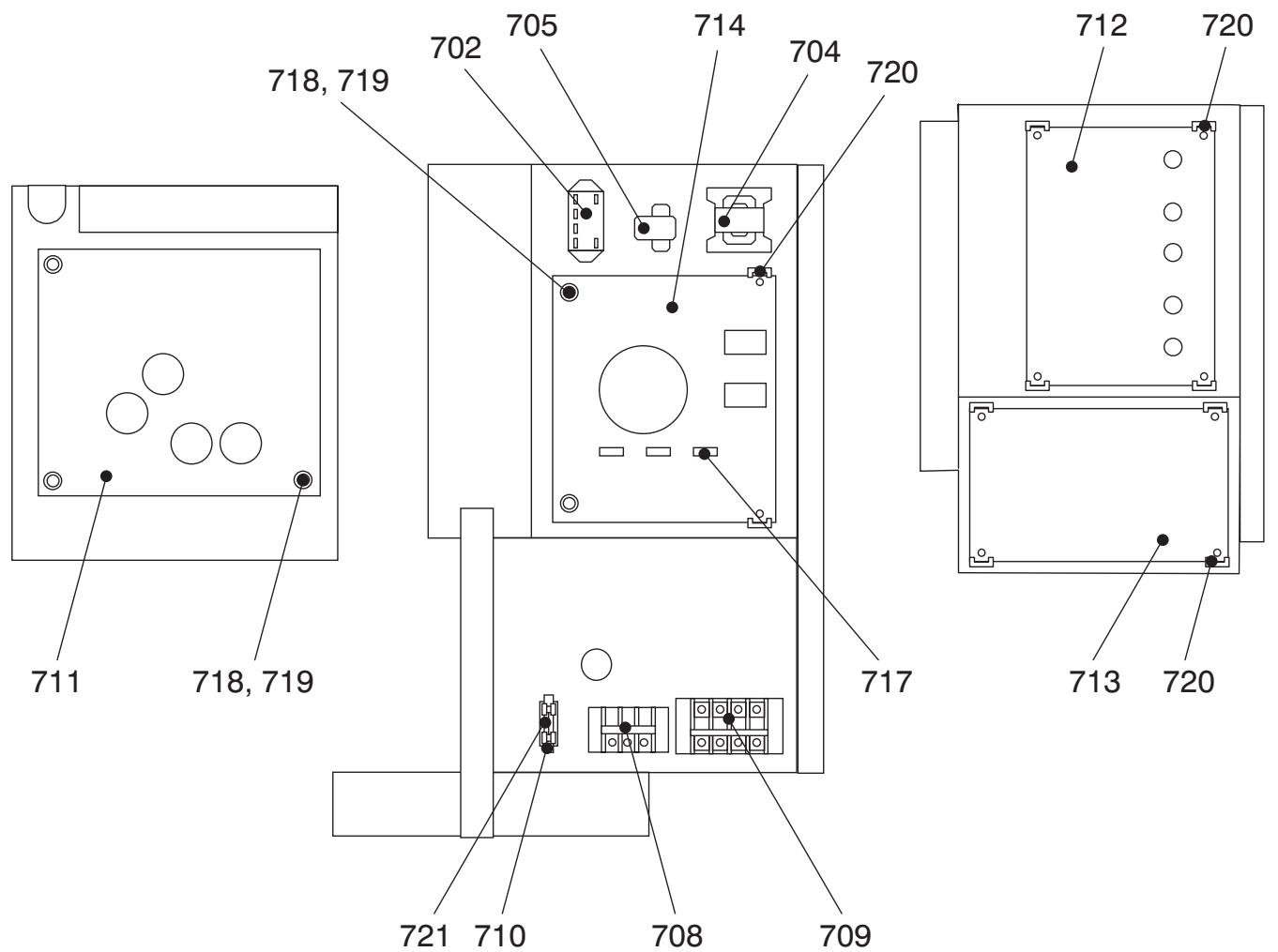
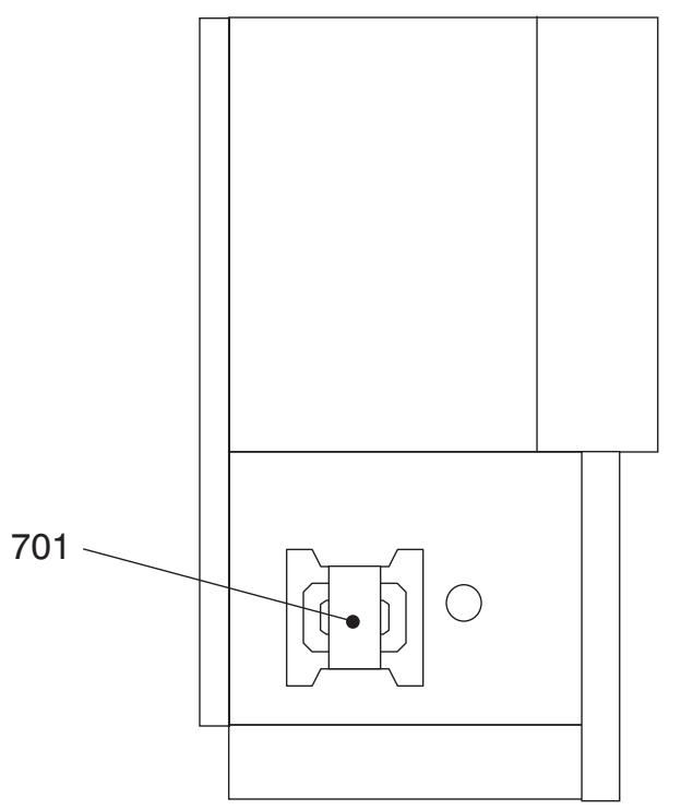

| Location No. | Part No. | Description | Model name RAV-SP | ||
| 1104AT8-E 1104AT8-TR 1104AT7 | 1104AT8Z-E 1104AT8Z-TR 1104AT7Z | 1104AT8ZG-E 1104AT8ZG-TR 1104AT7ZG | |||
| 701 | 43058288 | Reactor, CH-56-4Z | 1 | 1 | 1 |
| 702 | 43154177 | Relay, 480V, 20A | 1 | 1 | 1 |
| 704 | 43158207 | Reactor, CH-68 | 1 | 1 | 1 |
| 705 | 43153006 | PTC-Thermistor, ZPROYCE101A500 | 1 | 1 | 1 |
| 706 | 43050425 | Sensor Ass'y, TC (F6) | 3 | 3 | 3 |
| 707 | 43150319 | Sensor Ass'y, TD (F4) | 2 | 2 | 2 |
| 708 | 43160565 | Terminal Block, 3P, 20A, AC250A | 1 | 1 | 1 |
| 709 | 43160579 | Terminal, 30A, 4P | 1 | 1 | 1 |
| 710 | 43060859 | Fuse Block, 30A, 250V, FH153-PB | 1 | 1 | 1 |
| 711 | 4316V416 | P.C. Board Ass'y, MCC-1596, Comp.-IPDU | 1 | 1 | 1 |
| 712 | 4316V391 | P.C. Board Ass'y, MCC-1597, Fan-IPDU | 1 | 1 | 1 |
| 713 | 4316V417 | P.C. Board Ass'y, MCC-1599, CDB | 1 | 1 | 1 |
| 714 | 4316V398 | P.C. Board Ass'y, MCC-1600, N/F | 1 | 1 | 1 |
| 715 | 43063325 | Holder, Sensor | 1 | 1 | 1 |
| 717 | 43160590 | Fuse, 6.3A, AC250V | 3 | 3 | 3 |
| 718 | 43282001 | Bushing | 5 | 5 | 5 |
| 719 | 43183020 | Collar | 5 | 5 | 5 |
| 720 | 43063248 | Supporter Ass'y | 2 | 2 | 2 |
| 721 | 43060700 | Fuse, 10A, 250V | 1 | 1 | 1 |
Outdoor Unit
RAV-SP1404AT8-E, RAV-SP1404AT8Z-E, RAV-SP1404AT8ZG-E
RAV-SP1404AT8-TR, RAV-SP1404AT8Z-TR, RAV-SP1404AT8ZG-TR
RAV-SP1404AT7, RAV-SP1404AT7Z, RAV-SP1404AT7ZG
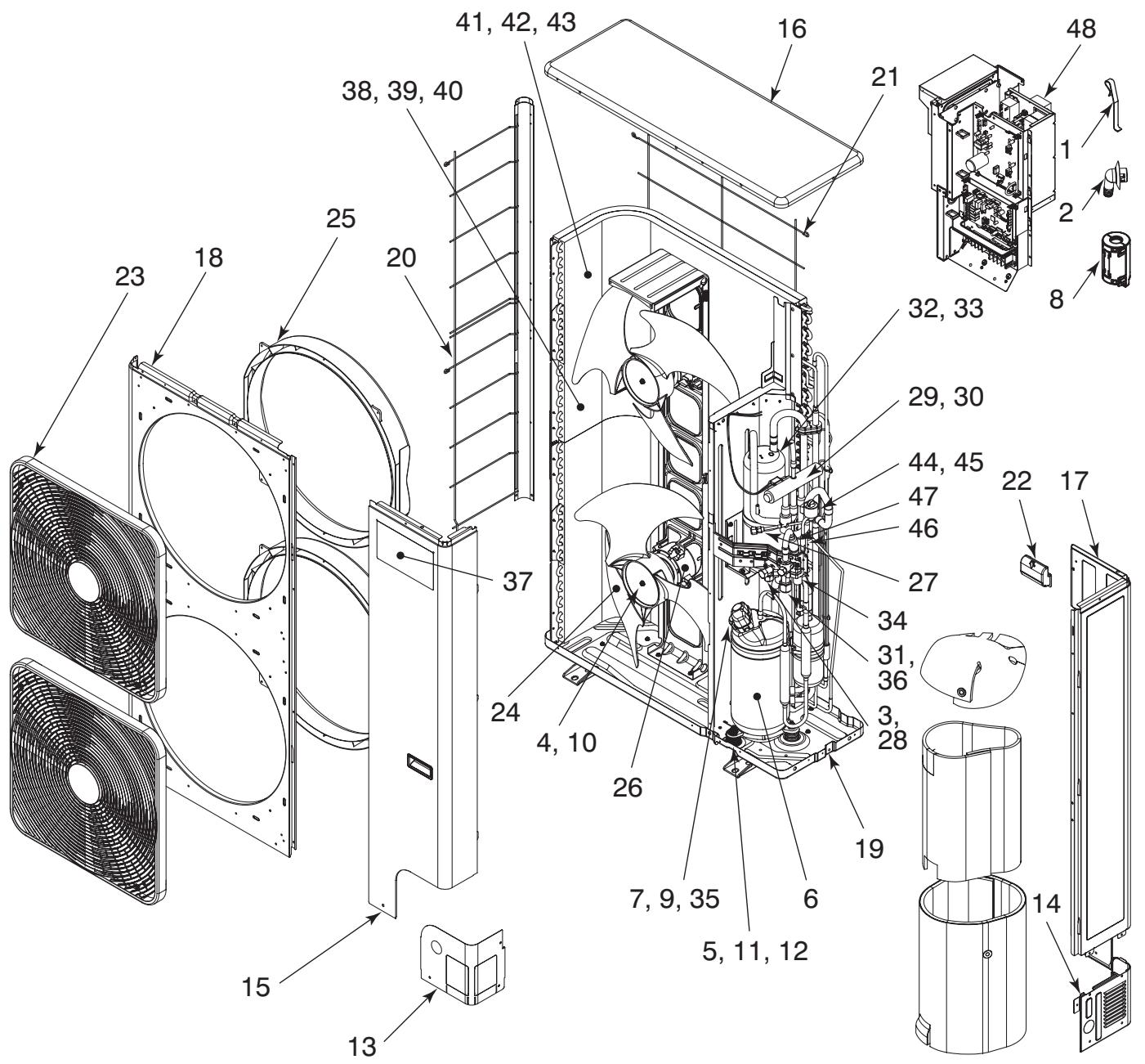
| Location No. | Part No. | Description | Model name RAV-SP | ||
| 1404AT8-E 1404AT8-TR 1404AT7 | 1404AT8Z-E 1404AT8Z-TR 1404AT7Z | 1404AT8ZG-E 1404AT8ZG-TR 1404AT7ZG | |||
| 1 | 43019904 | Holder, Sensor | 3 | 3 | 3 |
| 2 | 43032441 | Nipple, Drain | 1 | 1 | 1 |
| 3 | 43047246 | Bonnet, 3/8 IN | 1 | 1 | 1 |
| 4 | 43047669 | Nut, Flange | 2 | ||
| 5 | 43049739 | Cushion, Rubber | 3 | 3 | 3 |
| 6 | 4304C703 | Compressor, DA422A3F-27M | 1 | 1 | 1 |
| 7 | 43050407 | Thermostat, Bimetal | 1 | 1 | 1 |
| 8 | 43060029 | Filter, Noise | 1 | 1 | 1 |
| 9 | 43063317 | Holder, Thermostat | 1 | 1 | 1 |
| 10 | 43197164 | Nut, Flange | 2 | 2 | |
| 11 | 43197174 | Nut, Comp. | 3 | 3 | |
| 12 | 43097212 | Nut, Comp. | 3 | ||
| 13 | 43100437 | Panel, Front, Piping | 1 | 1 | 1 |
| 14 | 43100438 | Panel, Back, Piping | 1 | 1 | 1 |
| 15 | 43100439 | Panel, Front | 1 | 1 | 1 |
| 16 | 43100440 | Plate, Roof | 1 | 1 | 1 |
| 17 | 43100470 | Panel, Side | 1 | 1 | 1 |
| 18 | 43100442 | Panel, Air Outlet | 1 | 1 | 1 |
| 19 | 43100443 | Base Ass'y | 1 | 1 | 1 |
| 20 | 43107274 | Guard, Fin, Side | 1 | 1 | 1 |
| 21 | 43107275 | Guard, Fin, Back | 1 | 1 | 1 |
| 22 | 43107276 | Hanger | 3 | 3 | 3 |
| 23 | 43109422 | Guard, Fan | 2 | 2 | 2 |
| 24 | 43120244 | Fan, Propeller, PB521 | 2 | 2 | 2 |
| 25 | 43122113 | Bell Mouth | 2 | 2 | 2 |
| 26 | 4312C037 | Motor, Fan, ICF-280-A100-1 | 2 | 2 | 2 |
| 27 | 43146676 | Joint, Check | 1 | 1 | 1 |
| 28 | 43146686 | Valve, Packed, 9.52 | 1 | 1 | 1 |
| 29 | 43146687 | Valve, 4-Way, STF-0401G | 1 | 1 | 1 |
| 30 | 43146722 | Coil, Solenoid, STF-01AJ502E1 | 1 | 1 | 1 |
| 31 | 43146724 | Valve, Ball, SBV-JA5GTC-1, RoHs | 1 | 1 | 1 |
| 32 | 43148170 | Accumulator, 2.5L | 1 | 1 | |
| 33 | 43148188 | Accumulator, 2.5L | 1 | ||
| 34 | 43151301 | Switch, Pressure | 1 | 1 | 1 |
| 35 | 43160612 | Lead Ass'y, Compressor | 1 | 1 | 1 |
| 36 | 43194029 | Bonnet | 1 | 1 | 1 |
| 37 | 4311M659 | Mark, TOSHIBA | 1 | 1 | 1 |
| 38 | 4314G266 | Condenser Ass'y, Down | 1 | ||
| 39 | 4314G267 | Condenser Ass'y, Down | 1 | ||
| 40 | 4314G268 | Condenser Ass'y, Down | 1 | ||
| 41 | 4314G269 | Condenser Ass'y, Up | 1 | ||
| 42 | 4314G270 | Condenser Ass'y, Up | 1 | ||
| 43 | 4314G271 | Condenser Ass'y, Up | 1 | ||
| 44 | 4314N023 | Valve, Plus, Moduling, UKV-25D100 | 1 | 1 | 1 |
| 45 | 4314N025 | Coil, PMV, UKV-A038 | 1 | 1 | 1 |
| 46 | 4314Q031 | Strainer, 9.52 | 1 | 1 | 1 |
| 47 | 4314Q032 | Strainer | 1 | 1 | 1 |
| 48 | 43158227 | Reactor, CH-78-FC | 1 | 1 | 1 |
Inverter Unit
RAV-SP1404AT8-E, RAV-SP1404AT8Z-E, RAV-SP1404AT8ZG-E
RAV-SP1404AT8-TR, RAV-SP1404AT8Z-TR, RAV-SP1404AT8ZG-TR
RAV-SP1404AT7, RAV-SP1404AT7Z, RAV-SP1404AT7ZG


| Location No. | Part No. | Description | Model name RAV-SP | ||
| 1404AT8-E 1404AT8-TR 1404AT7 | 1404AT8Z-E 1404AT8Z-TR 1404AT7Z | 1404AT8ZG-E 1404AT8ZG-TR 1404AT7ZG | |||
| 701 | 43058288 | Reactor, CH-56-4Z | 1 | 1 | 1 |
| 702 | 43154177 | Relay, 480V, 20A | 1 | 1 | 1 |
| 704 | 43158207 | Reactor, CH-68 | 1 | 1 | 1 |
| 705 | 43153006 | PTC-Thermistor, ZPROYCE101A500 | 1 | 1 | 1 |
| 706 | 43050425 | Sensor Ass'y, TC (F6) | 3 | 3 | 3 |
| 707 | 43150319 | Sensor Ass'y, TD (F4) | 2 | 2 | 2 |
| 708 | 43160565 | Terminal Block, 3P, 20A, AC250A | 1 | 1 | 1 |
| 709 | 43160579 | Terminal, 30A, 4P | 1 | 1 | 1 |
| 710 | 43060859 | Fuse Block, 30A, 250V, FH153-PB | 1 | 1 | 1 |
| 711 | 4316V416 | P.C. Board Ass'y, MCC-1596, Comp.-IPDU | 1 | 1 | 1 |
| 712 | 4316V391 | P.C. Board Ass'y, MCC-1597, Fan-IPDU | 1 | 1 | 1 |
| 713 | 4316V417 | P.C. Board Ass'y, MCC-1599, CDB | 1 | 1 | 1 |
| 714 | 4316V398 | P.C. Board Ass'y, MCC-1600, N/F | 1 | 1 | 1 |
| 715 | 43063325 | Holder, Sensor | 1 | 1 | 1 |
| 717 | 43160590 | Fuse, 6.3A, AC250V | 3 | 3 | 3 |
| 718 | 43282001 | Bushing | 5 | 5 | 5 |
| 719 | 43183020 | Collar | 5 | 5 | 5 |
| 720 | 43063248 | Supporter Ass'y | 2 | 2 | 2 |
| 721 | 43060700 | Fuse, 10A, 250V | 1 | 1 | 1 |
Outdoor Unit
RAV-SP1604AT8-E, RAV-SP1604AT8Z-E, RAV-SP1604AT8ZG-E
RAV-SP1604AT8-TR, RAV-SP1604AT8Z-TR, RAV-SP1604AT8ZG-TR
RAV-SP1604AT7, RAV-SP1604AT7Z, RAV-SP1604AT7ZG
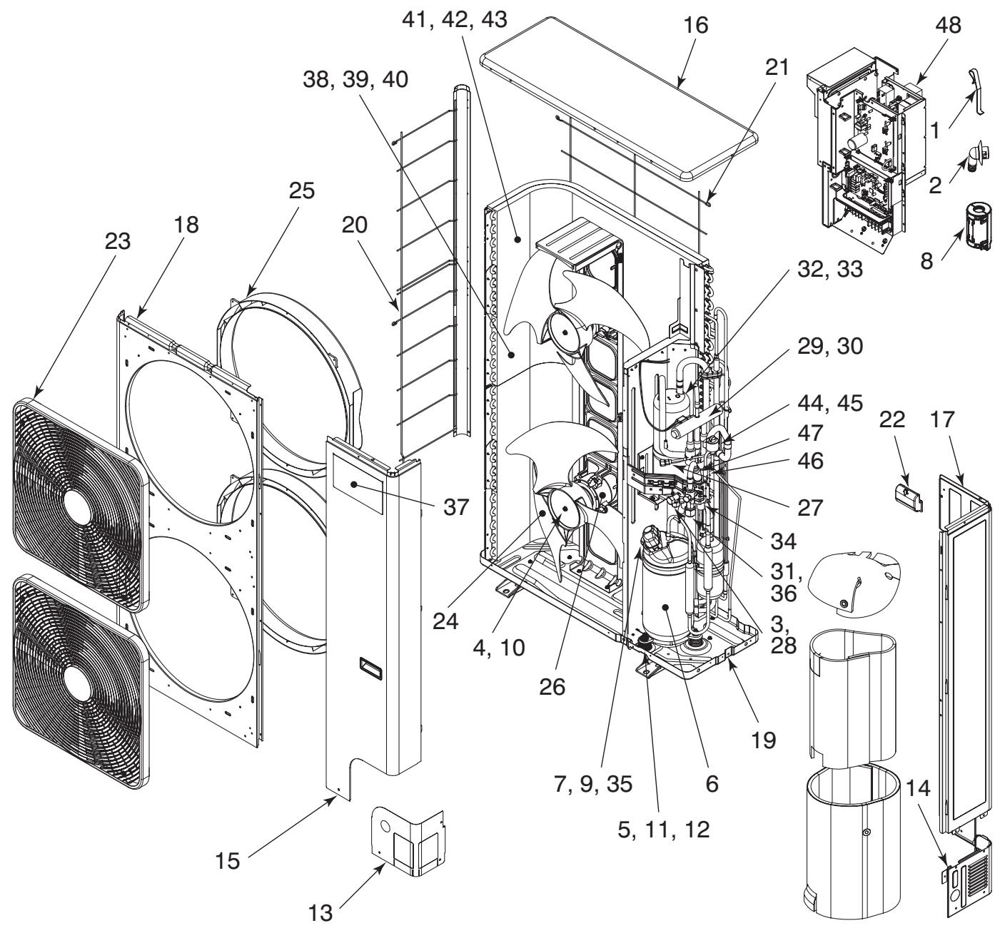
| Location No. | Part No. | Description | Model name RAV-SP | ||
| 1604AT8-E 1604AT8-TR 1604AT7 | 1604AT8Z-E 1604AT8Z-TR 1604AT7Z | 1604AT8ZG-E 1604AT8ZG-TR 1604AT7ZG | |||
| 1 | 43019904 | Holder, Sensor | 3 | 3 | 3 |
| 2 | 43032441 | Nipple, Drain | 1 | 1 | 1 |
| 3 | 43047246 | Bonnet, 3/8 IN | 1 | 1 | 1 |
| 4 | 43047669 | Nut, Flange | 2 | ||
| 5 | 43049739 | Cushion, Rubber | 3 | 3 | 3 |
| 6 | 4304C703 | Compressor, DA422A3F-27M | 1 | 1 | 1 |
| 7 | 43050407 | Thermostat, Bimetal | 1 | 1 | 1 |
| 8 | 43060029 | Filter, Noise | 1 | 1 | 1 |
| 9 | 43063317 | Holder, Thermostat | 1 | 1 | 1 |
| 10 | 43197164 | Nut, Flange | 2 | 2 | |
| 11 | 43197174 | Nut, Comp. | 3 | 3 | |
| 12 | 43097212 | Nut, Comp. | 3 | ||
| 13 | 43100437 | Panel, Front, Piping | 1 | 1 | 1 |
| 14 | 43100438 | Panel, Back, Piping | 1 | 1 | 1 |
| 15 | 43100439 | Panel, Front | 1 | 1 | 1 |
| 16 | 43100440 | Plate, Roof | 1 | 1 | 1 |
| 17 | 43100470 | Panel, Side | 1 | 1 | 1 |
| 18 | 43100442 | Panel, Air Outlet | 1 | 1 | 1 |
| 19 | 43100443 | Base Ass'y | 1 | 1 | 1 |
| 20 | 43107274 | Guard, Fin, Side | 1 | 1 | 1 |
| 21 | 43107275 | Guard, Fin, Back | 1 | 1 | 1 |
| 22 | 43107276 | Hanger | 3 | 3 | 3 |
| 23 | 43109422 | Guard, Fan | 2 | 2 | 2 |
| 24 | 43120244 | Fan, Propeller, PB521 | 2 | 2 | 2 |
| 25 | 43122113 | Bell Mouth | 2 | 2 | 2 |
| 26 | 4312C037 | Motor, Fan, ICF-280-A100-1 | 2 | 2 | 2 |
| 27 | 43146676 | Joint, Check | 1 | 1 | 1 |
| 28 | 43146686 | Valve, Packed, 9.52 | 1 | 1 | 1 |
| 29 | 43146687 | Valve, 4-Way, STF-0401G | 1 | 1 | 1 |
| 30 | 43146722 | Coil, Solenoid, STF-01AJ502E1 | 1 | 1 | 1 |
| 31 | 43146724 | Valve, Ball, SBV-JA5GTC-1, RoHs | 1 | 1 | 1 |
| 32 | 43148170 | Accumulator, 2.5L | 1 | 1 | |
| 33 | 43148188 | Accumulator, 2.5L | 1 | ||
| 34 | 43151301 | Switch, Pressure | 1 | 1 | 1 |
| 35 | 43160612 | Lead Ass'y, Compressor | 1 | 1 | 1 |
| 36 | 43194029 | Bonnet | 1 | 1 | 1 |
| 37 | 4311M659 | Mark, TOSHIBA | 1 | 1 | 1 |
| 38 | 4314G266 | Condenser Ass'y, Down | 1 | ||
| 39 | 4314G267 | Condenser Ass'y, Down | 1 | ||
| 40 | 4314G268 | Condenser Ass'y, Down | 1 | ||
| 41 | 4314G269 | Condenser Ass'y, Up | 1 | ||
| 42 | 4314G270 | Condenser Ass'y, Up | 1 | ||
| 43 | 4314G271 | Condenser Ass'y, Up | 1 | ||
| 44 | 4314N023 | Valve, Plus, Moduling, UKV-25D100 | 1 | 1 | 1 |
| 45 | 4314N025 | Coil, PMV, UKV-A038 | 1 | 1 | 1 |
| 46 | 4314Q031 | Strainer, 9.52 | 1 | 1 | 1 |
| 47 | 4314Q032 | Strainer | 1 | 1 | 1 |
| 48 | 43158227 | Reactor, CH-78-FC | 1 | 1 | 1 |
Inverter Unit
RAV-SP1604AT8-E, RAV-SP1604AT8Z-E, RAV-SP1604AT8ZG-E}
RAV-SP1604AT8-TR, RAV-SP1604AT8Z-TR, RAV-SP1604AT8ZG-TR
RAV-SP1604AT7, RAV-SP1604AT7Z, RAV-SP1604AT7ZG

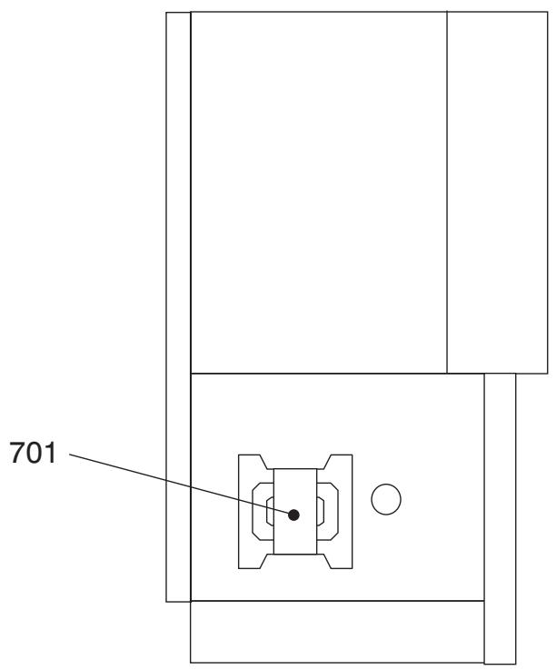
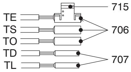
| Location No. | Part No. | Description | Model name RAV-SP | ||
| 1604AT8-E 1604AT8-TR 1604AT7 | 1604AT8Z-E 1604AT8Z-TR 1604AT7Z | 1604AT8ZG-E 1604AT8ZG-TR 1604AT7ZG | |||
| 701 | 43058288 | Reactor, CH-56-4Z | 1 | 1 | 1 |
| 702 | 43154177 | Relay, 480V, 20A | 1 | 1 | 1 |
| 704 | 43158207 | Reactor, CH-68 | 1 | 1 | 1 |
| 705 | 43153006 | PTC-Thermistor, ZPROYCE101A500 | 1 | 1 | 1 |
| 706 | 43050425 | Sensor Ass'y, TC (F6) | 3 | 3 | 3 |
| 707 | 43150319 | Sensor Ass'y, TD (F4) | 2 | 2 | 2 |
| 708 | 43160565 | Terminal Block, 3P, 20A, AC250A | 1 | 1 | 1 |
| 709 | 43160579 | Terminal, 30A, 4P | 1 | 1 | 1 |
| 710 | 43060859 | Fuse Block, 30A, 250V, FH153-PB | 1 | 1 | 1 |
| 711 | 4316V416 | P.C. Board Ass'y, MCC-1596, Comp.-IPDU | 1 | 1 | 1 |
| 712 | 4316V391 | P.C. Board Ass'y, MCC-1597, Fan-IPDU | 1 | 1 | 1 |
| 713 | 4316V417 | P.C. Board Ass'y, MCC-1599, CDB | 1 | 1 | 1 |
| 714 | 4316V398 | P.C. Board Ass'y, MCC-1600, N/F | 1 | 1 | 1 |
| 715 | 43063325 | Holder, Sensor | 1 | 1 | 1 |
| 717 | 43160590 | Fuse, 6.3A, AC250V | 3 | 3 | 3 |
| 718 | 43282001 | Bushing | 5 | 5 | 5 |
| 719 | 43183020 | Collar | 5 | 5 | 5 |
| 720 | 43063248 | Supporter Ass'y | 2 | 2 | 2 |
| 721 | 43060700 | Fuse, 10A, 250V | 1 | 1 | 1 |
WARNING ON REFRIGERANT LEAKAGE
Check of Concentration Limit
The room in which the air conditioner is to be installed requires a design that in the event of refrigerant gas leaking out, its concentration will not exceed a set limit.
The refrigerant R410A which is used in the air conditioner is safe, without the toxicity or combustibility of ammonia, and is not restricted by laws to be imposed which protect the ozone layer.
However, since it contains more than air, it poses the risk of suffocation if its concentration should rise excessively. Suffocation from leakage of R410A is almost non-existent.
With the recent increase in the number of high concentration buildings, however, the installation of multi air conditioner systems is on the increase because of the need for effective use of floor space, individual control, energy conservation by curtailing heat and carrying power etc.
Most importantly, the multi air conditioner system is able to replenish a large amount of refrigerant compared with conventional individual air conditioners.
If a single unit of the multi conditioner system is to be installed in a small room, select a suitable model and installation procedure so that if the refrigerant accidentally leaks out, its concentration does not reach the limit (and in the event of an emergency, measures can be made before injury can occur).
In a room where the concentration may exceed the limit, create an opening with adjacent rooms, or install mechanical ventilation combined with a gas leak detection device.
The concentration is as given below.
Total amount of refrigerant (kg)
Min. volume of the indoor unit installed room (^3)
≤ Concentration limit (kg / m^3)
The concentration limit of R410A which is used in multi air conditioners is 0.3kg / m^3
NOTE 1:
If there are 2 or more refrigerating systems in a single refrigerating device, the amounts of refrigerant should be as charged in each independent device.
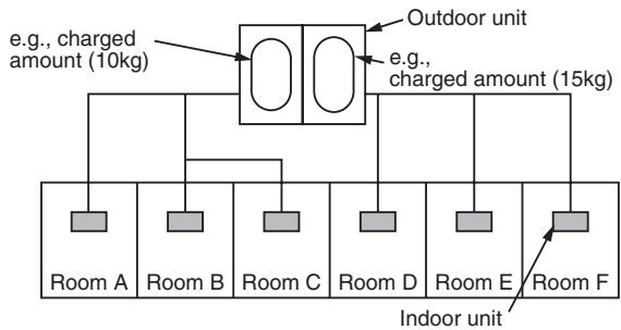
For the amount of charge in this example:
The possible amount of leaked refrigerant gas in rooms A, B and C is 10kg .
The possible amount of leaked refrigerant gas in rooms D, E and F is 15kg
Important
NOTE 2 :
The standards for minimum room volume are as follows.
(1) No partition (shaded portion)
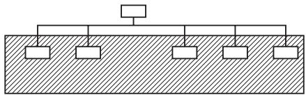
(2) When there is an effective opening with the adjacent room for ventilation of leaking refrigerant gas (opening without a door, or an opening 0.15% or larger than the respective floor spaces at the top or bottom of the door).
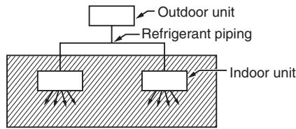
(3) If an indoor unit is installed in each partitioned room and the refrigerant piping is interconnected, the smallest room of course becomes the object. But when a mechanical ventilation is installed interlocked with a gas leakage detector in the smallest room where the density limit is exceeded, the volume of the next smallest room becomes the object. Refrigerant piping
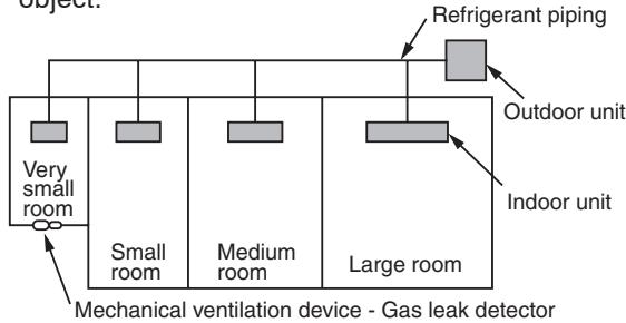
NOTE 3 :
The minimum indoor floor area compared with the amount of refrigerant is roughly as follows:
(When the ceiling is 2.7m high)
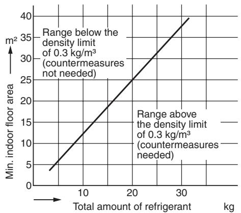
TOSHIBA CARRIER CORPORATION
Copyright © 1999 to 2010 TOSHIBA CARRIER CORPORATION, ALL Rights Reserved.