
RAV-SM801KRT-E - Air-conditioner TOSHIBA - Free user manual and instructions
Find the device manual for free RAV-SM801KRT-E TOSHIBA in PDF.

User questions about RAV-SM801KRT-E TOSHIBA
0 question about this device. Answer the ones you know or ask your own.
Ask a new question about this device
Download the instructions for your Air-conditioner in PDF format for free! Find your manual RAV-SM801KRT-E - TOSHIBA and take your electronic device back in hand. On this page are published all the documents necessary for the use of your device. RAV-SM801KRT-E by TOSHIBA.
USER MANUAL RAV-SM801KRT-E TOSHIBA
This Service Manual describes explanation for the Under Ceiling type indoor unit. For the combined outdoor unit, refer to the following Service Manual.
Outdoor unit Model name
SVM to be referred
RAV-SMXX0AT-E
A03-007
RAV-SPXXXAT-E
A03-014
RAV-SMX1AT-E
A05-001
1. SPECIFICATIONS
1-1. High-Wall Type (Indoor Unit)
| Model name | RAV-SM561KRT-E | RAV-SM801KRT-E | ||||||
| Standard capacity (Note 1) (kW) | Cooling | Heating | Average | Cooling | Heating | Average | ||
| 5.1(1.5-5.6) | 5.6(1.5-6.3) | 6.7(2.2-8.0) | 8(2.2-9.0) | |||||
| Heating low temp. capacity (Note 1) (kW) | 4.9 | 5.8 | ||||||
| Energy consumption effect ratio (Cooling) | 2.93 [D] | 3.29 [C] | 3.11 | 2.46 [E] | 3.00 [D] | 3.24 | ||
| Electrical characteristics | Power supply | 1 phase 230V (220 - 240V) 50Hz | ||||||
| Running current (A) | 8.33-7.63 | 8.138-7.46 | 13.15-12.05 | 12.91-11.84 | ||||
| Power consumption (kW)(Low temp.) (kW) | 1.74 | 1.7 | 2.72 | 2.67 | ||||
| 1.95 | 2.21 | |||||||
| Power factor (%) | 95 | 95 | 94 | 94 | ||||
| Appearance | Main unit | Pure white | ||||||
| Ceiling Panel(Sold separately) | Model | — | ||||||
| Panel color | — | |||||||
| Outer dimension | Main unit | Height (mm) | 298 | |||||
| Width (mm) | 998 | |||||||
| Depth (mm) | 208 | |||||||
| Ceiling panel(Sold separately) | Height (mm) | — | ||||||
| Width (mm) | — | |||||||
| Depth (mm) | — | |||||||
| Total weight | Main unit (kg) | 12 | ||||||
| Ceiling panel | — | |||||||
| Heat exchanger | Finned tubu | |||||||
| Soundproof/Heat-insulating material | Inflammable polyethylene foam | Foamed polyethylen | ||||||
| Fan unit | Fan | Turbo fan | ||||||
| Standard air flow High (Mid./Low) (m³/h) | 840 | 1110 | ||||||
| Motor (W) | 30 | |||||||
| Air filter | Attached main unit | |||||||
| Controller (Sold separately) | Wired remote controller RBC-AMT21E | |||||||
| Connecting pipe | Gas side (mm) | Ø12.7 (1/2") | Ø15.9 (5/8") | |||||
| Liquid side (mm) | Ø6.4 (1/4") | Ø9.5 (3/8") | ||||||
| Drain port (Nominal dia.) | 25 (Polyvinyl chloride tube) | |||||||
| Sound levelHigh (Mid./Low) (Note 2) (dB·A) | 45 | 41 | 36 | 45 | 41 | 36 | ||
Note 1 : The cooling capacities and electrical characteristics are measured under the conditions specied by JIS B 8616 based on the reference piping. The reference piping consists of 3m of main piping and 2m of branch piping connected with 0 meter height.
Note 2 : The sound level is measured in an anechoic chamber in accordance with JIS B8616. Normally, the values measured in the actual operating environment become larger than the indicated values due to the effects of external sound.
Note : Rated conditions
Cooling: Indoor air temperature 27^ DB/19°C WB, Outdoor air temperature 35^ DB
Heating : Indoor air temperature 20°C DB, Outdoor air temperature 7°C DB/6°C WB
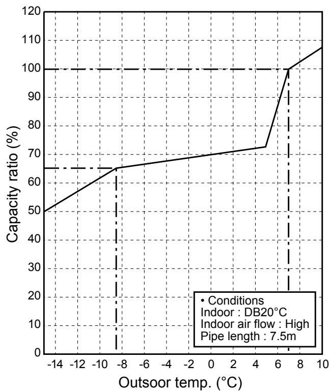
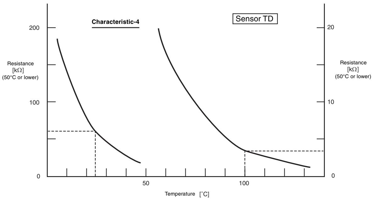
Operation characteristic curve
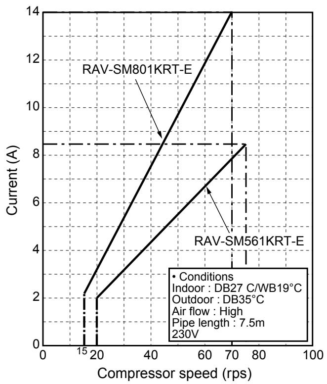
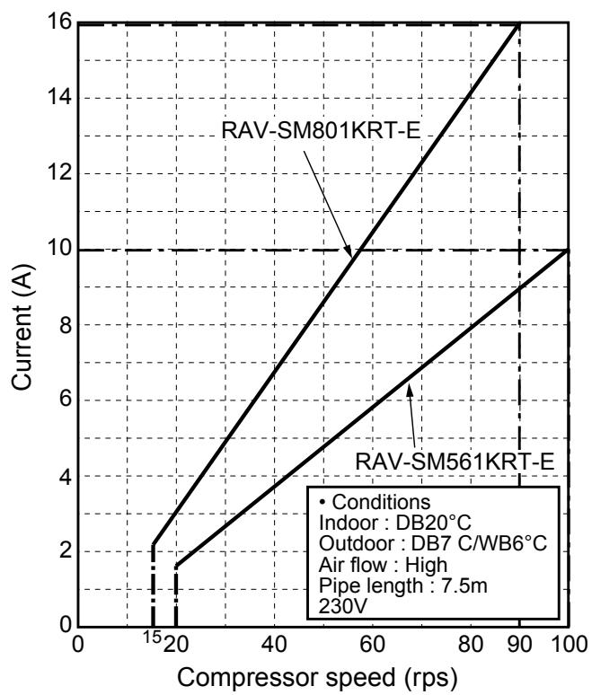
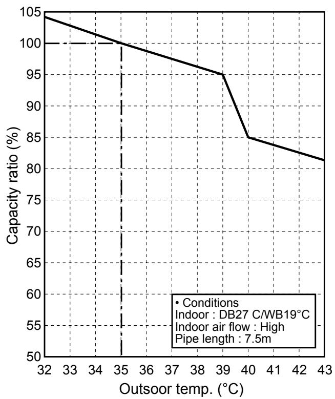
- Capacity variation ratioaccor ding to temperature
2. CONSTRUCTION VIEWS (EXTERNAL VIEWS)
High-Wall Type
RAV-SM561KRT-E/RAV-SM801KRT-E
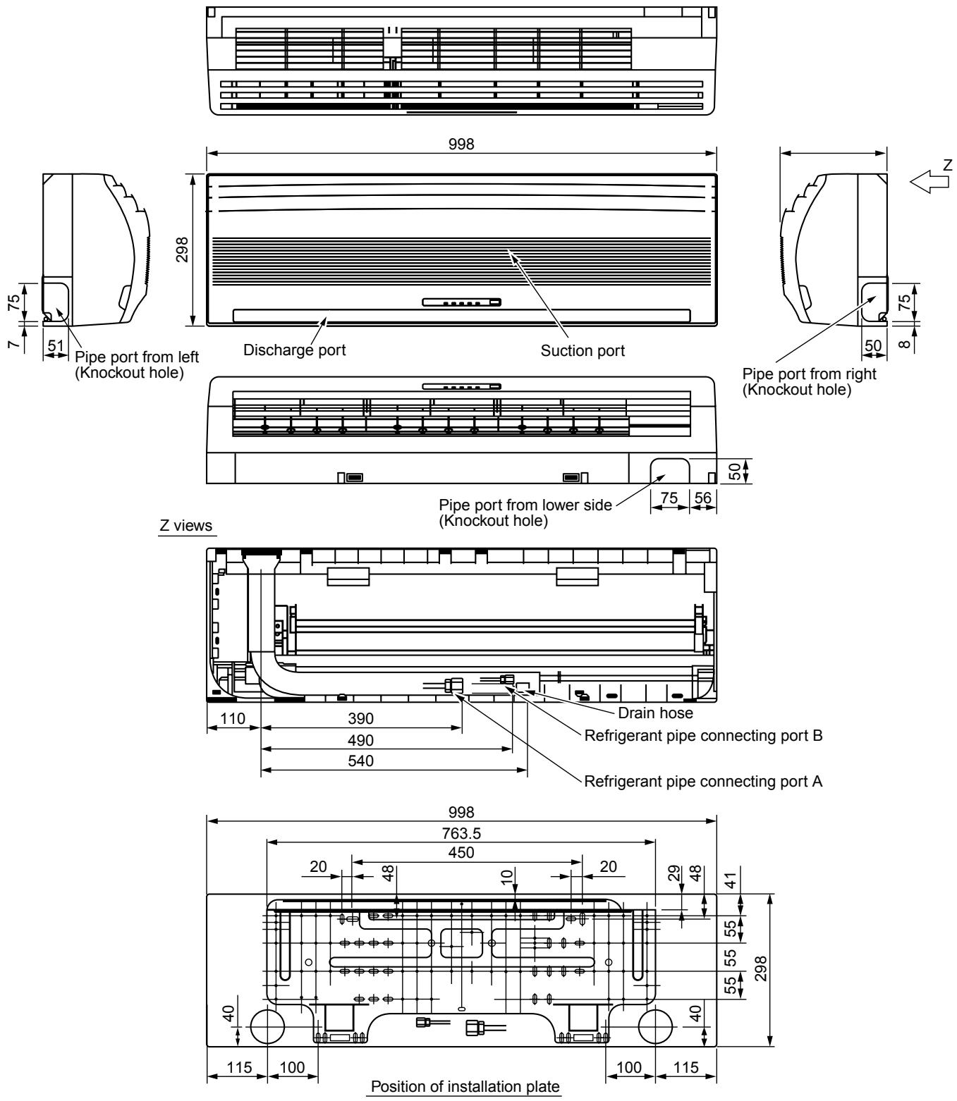
| A Liquid Side | B Gas Side | |
| SM561 | Ø6.4 | Ø12.7 |
| SM801 | Ø9.5 | Ø15.9 |
*If use central control, keep 200mm or more to maintenaiice.
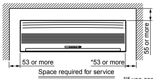
3. SYSTEMATIC REFRIGERATING CYCLE DIAGRAM
3-1. Hi Wall type
RAV-SM561KRT-E/SM801KRT-E
| Model RAV-SM | Outer diameter of refrigérant pipe | |
| Gas side ØA | Liquid side ØB | |
| 561KRT-E | 12.7 mm | 6.4 mm |
| 801KRT-E | 15.9 mm | 9.5 mm |
NOTE :
The refrigerating cycle differs according to the combined outdoor units.
For the cycle diagram, cycle pressure, etc., refer to the following Service Manual.
RAV-SMXXX0AT-E:A03-007
RAV-SPXXXXAT-E : A03-014
RAV-SMXXX1AT-E : A05-001
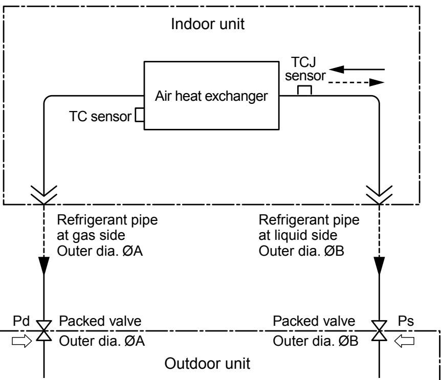
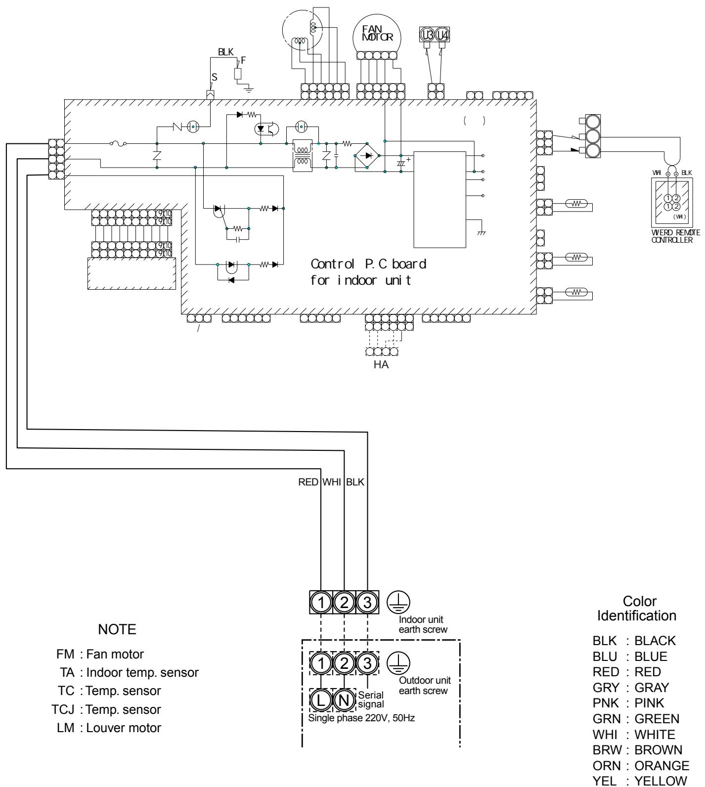
4. WIRING DIAGRAM
4-1. Hi Wall type (Indoor unit)
RAV-SM561KRT-E/SM801KRT-E
5. SPECIFICATIONS OF ELECTRICAL PARTS
5-1. Indoor Unit
High-Wall Type
RAV-SM561KRT-E/RAV-SM801KRT-E
| No. | Parts name | Type | Specifications |
| 1 | Fan motor (for indoor) | ICF340-30-X MF-340-30-X | Output (Rated) 30 W, 220–240 V |
| 2 | Grille motor | MP35EA12 | |
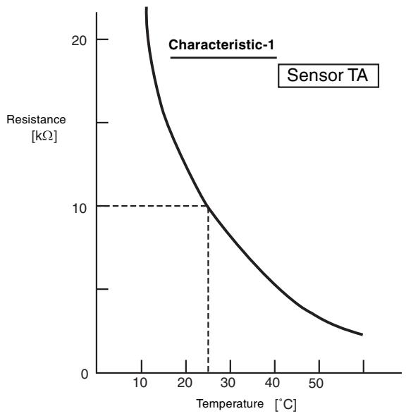
| 3 | Thermo. sensor (TA-sensor) | 268 mm | 10 kΩ at 25°C |
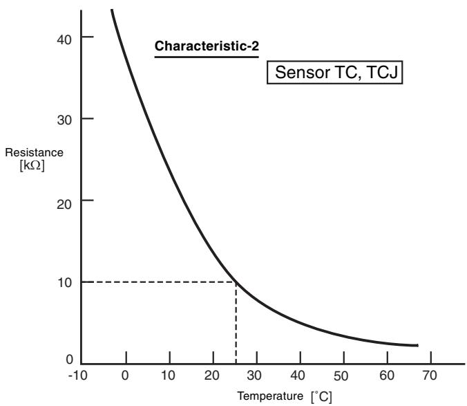
| 4 | Heat exchanger sensor (TC-sensor) | Ø6 mm, 400 mm | 10 kΩ at 25°C |
| 5 | Heat exchanger sensor (TCJ-sensor) | Ø6 mm, 400 mm |
6. REFRIGERANT R410A
This air conditioner adopts the new refrigerant HFC (R410A) which does not damage the ozone layer.
The working pressure of the new refrigerant R410A is 1.6 times higher than conventional refrigerant (R22). The refrigerating oil is also changed in accordance with change of refrigerant, so be careful that water, dust, and existing refrigerant or refrigerating oil are not entered in the refrigerant cycle of the air conditioner using the new refrigerant during installation work or servicing time.
The next section describes the precautions for air conditioner using the new refrigerant. Conforming to contents of the next section together with the general cautions included in this manual, perform the correct and safe work.
6-1. Safety During Installation/Servicing
As R410A's pressure is about 1.6 times higher than that of R22, improper installation/servicing may cause a serious trouble. By using tools and materials exclusive for R410A, it is necessary to carry out installation/servicing safely while taking the following precautions into consideration.
(1) Never use refrigerant other than R410A in an air conditioner which is designed to operate with R410A.
If other refrigerant than R410A is mixed, pressure in the refrigeration cycle becomes abnormally high, and it may cause personal injury, etc. by a rupture.
(2) Confirm the used refrigerant name, and use tools and materials exclusive for the refrigerant R410A.
The refrigerant name R410A is indicated on the visible place of the outdoor unit of the air conditioner using R410A as refrigerant. To prevent mischarging, the diameter of the service port differs from that of R22.
(3) If a refrigeration gas leakage occurs during installation/servicing, be sure to ventilate fully. If the refrigerant gas comes into contact with fire, a poisonous gas may occur.
(4) When installing or removing an air conditioner, do not allow air or moisture to remain in the refrigeration cycle. Otherwise, pressure in the refrigeration cycle may become abnormally high so that a rupture or personal injury may be caused.
(5) After completion of installation work, check to make sure that there is no refrigeration gas leakage. If the refrigerant gas leaks into the room, coming into contact with fire in the fan-driven heater, space heater, etc., a poisonous gas may occur.
(6) When an air conditioning system charged with a large volume of refrigerant is installed in a small room, it is necessary to exercise care so that, even when refrigerant leaks, its concentration does not exceed the marginal level.
If the refrigerant gas leakage occurs and its concentration exceeds the marginal level, an oxygen starvation accident may result.
(7) Be sure to carry out installation or removal according to the installation manual.
Improper installation may cause refrigeration trouble, water leakage, electric shock, fire, etc.
(8) Unauthorized modifications to the air conditioner may be dangerous. If a breakdown occurs please call a qualified air conditioner technician or electrician.
Improper repair may result in water leakage, electric shock and fire, etc.
6-2. Refrigerant Piping Installation
6-2-1. Piping Materials and Joints Used
For the refrigerant piping installation, copper pipes and joints are mainly used. Copper pipes and joints suitable for the refrigerant must be chosen and installed. Furthermore, it is necessary to use clean copper pipes and joints whose interior surfaces are less affected by contaminants.
(1) Copper Pipes
It is necessary to use seamless copper pipes which are made of either copper or copper alloy and it is desirable that the amount of residual oil is less than 40mg / 10m . Do not use copper pipes having a collapsed, deformed or discolored portion (especially on the interior surface). Otherwise, the expansion valve or capillary tube may become blocked with contaminants.
As an air conditioner using R410A incurs pressure higher than when using R22, it is necessary to choose adequate materials.
Thickities of copper pipes used with R410A are as shown in Table 6-2-1. Never use copper pipes thinner than 0.8mm even when it is available on the market.
Table 6-2-1 Thicknesses of annealed copper pipes
| Thickness (mm) | |||
| Nominal diameter | Outer diameter (mm) | R410A | R22 |
| 1/4 | 6.35 | 0.80 | 0.80 |
| 3/8 | 9.52 | 0.80 | 0.80 |
| 1/2 | 12.70 | 0.80 | 0.80 |
| 5/8 | 15.88 | 1.00 | 1.00 |
(2) Joints
For copper pipes, flare joints or socket joints are used. Prior to use, be sure to remove all contaminants.
a) Flare Joints
Flare joints used to connect the copper pipes cannot be used for pipings whose outer diameter exceeds 20mm . In such a case, socket joints can be used.
Sizes of flare pipe ends, flare joint ends and flare nuts are as shown in Tables 6-2-3 to 6-2-6 below.
b) Socket Joints
Socket joints are such that they are brazed for connections, and used mainly for thick pipings whose diameter is larger than 20~mm . Thicknesses of socket joints are as shown in Table 6-2-2.
Table 6-2-2 Minimum thicknesses of socket joints
| Nominal diameter | Reference outer diameter of copper pipe jointed (mm) | Minimum joint thickness (mm) |
| 1/4 | 6.35 | 0.50 |
| 3/8 | 9.52 | 0.60 |
| 1/2 | 12.70 | 0.70 |
| 5/8 | 15.88 | 0.80 |
6-2-2. Processing of Piping Materials
When performing the refrigerant piping installation, care should be taken to ensure that water or dust does not enter the pipe interior, that no other oil other than lubricating oils used in the installed air conditioner is used, and that refrigerant does not leak. When using lubricating oils in the piping processing, use such lubricating oils whose water content has been removed. When stored, be sure to seal the container with an airtight cap or any other cover.
(1) Flare Processing Procedures and Precautions
a) Cutting the Pipe
By means of a pipe cutter, slowly cut the pipes so that it is not deformed.
b) Removing Burrs and Chips
If the flared section has chips or burrs, refrigerant leakage may occur. Carefully remove all burrs and clean the cut surface before installation.
c) Insertion of Flare Nut
d) Flare Processing
Make certain that a clamp bar and copper pipe have been cleaned.
By means of the clamp bar, perform the flare processing correctly.
Use either a flare tool for R410A or conventional flare tool.
Flare processing dimensions differ according to the type of flare tool. When using a conventional flare tool, be sure to secure "dimension A" by using a gauge for size adjustment.
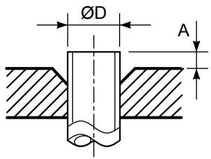
Fig. 6-2-1 Flare processing dimensions
Table 6-2-3 Dimensions related to flare processing for R410A
| Nominal diameter | Outer diameter (mm) | Thickness (mm) | A (mm) | ||
| Flare tool for R410A clutch type | Conventional flare tool | ||||
| Clutch type | Wing nut type | ||||
| 1/4 | 6.35 | 0.8 | 0 to 0.5 | 1.0 to 1.5 | 1.5 to 2.0 |
| 3/8 | 9.52 | 0.8 | 0 to 0.5 | 1.0 to 1.5 | 1.5 to 2.0 |
| 1/2 | 12.70 | 0.8 | 0 to 0.5 | 1.0 to 1.5 | 2.0 to 2.5 |
| 5/8 | 15.88 | 1.0 | 0 to 0.5 | 1.0 to 1.5 | 2.0 to 2.5 |
Table 6-2-4 Dimensions related to flare processing for R22
| Nominal diameter | Outer diameter (mm) | Thickness (mm) | A (mm) | ||
| Flare tool for R22 clutch type | Conventional flare tool | ||||
| Clutch type | Wing nut type | ||||
| 1/4 | 6.35 | 0.8 | 0 to 0.5 | 0.5 to 1.0 | 1.0 to 1.5 |
| 3/8 | 9.52 | 0.8 | 0 to 0.5 | 0.5 to 1.0 | 1.0 to 1.5 |
| 1/2 | 12.70 | 0.8 | 0 to 0.5 | 0.5 to 1.0 | 1.5 to 2.0 |
| 5/8 | 15.88 | 1.0 | 0 to 0.5 | 0.5 to 1.0 | 1.5 to 2.0 |
Table 6-2-5 Flare and flare nut dimensions for R410A
| Nominal diameter | Outer diameter (mm) | Thickness (mm) | Dimension (mm) | Flare nut width (mm) | |||
| A | B | C | D | ||||
| 1/4 | 6.35 | 0.8 | 9.1 | 9.2 | 6.5 | 13 | 17 |
| 3/8 | 9.52 | 0.8 | 13.2 | 13.5 | 9.7 | 20 | 22 |
| 1/2 | 12.70 | 0.8 | 16.6 | 16.0 | 12.9 | 23 | 26 |
| 5/8 | 15,88 | 1.0 | 19.7 | 19.0 | 16.0 | 25 | 29 |
Table 6-2-6 Flare and flare nut dimensions for R22
| Nominal diameter | Outer diameter (mm) | Thickness (mm) | Dimension (mm) | Flare nut width (mm) | |||
| A | B | C | D | ||||
| 1/4 | 6.35 | 0.8 | 9.0 | 9.2 | 6.5 | 13 | 17 |
| 3/8 | 9.52 | 0.8 | 13.0 | 13.5 | 9.7 | 20 | 22 |
| 1/2 | 12.70 | 0.8 | 16.2 | 16.0 | 12.9 | 20 | 24 |
| 5/8 | 15.88 | 1.0 | 19.4 | 19.0 | 16.0 | 23 | 27 |
| 3/4 | 19.05 | 1.0 | 23.3 | 24.0 | 19.2 | 34 | 36 |

Fig. 6-2-2 Relations between flare nut and flare seal surface
(2) Flare Connecting Procedures and Precautions
a) Make sure that the flare and union portions do not have any scar or dust, etc.
b) Correctly align the processed flare surface with the union axis.
c) Tighten the flare with designated torque by means of a torque wrench. The tightening torque for R410A is the same as that for conventional R22. Incidentally, when the torque is weak, the gas leakage may occur.
When it is strong, the flare nut may crack and may be made non-removable. When choosing the tightening torque, comply with values designated by manufacturers. Table 6-2-7 shows reference values.
NOTE:
When applying oil to the flare surface, be sure to use oil designated by the manufacturer. If any other oil is used, the lubricating oils may deteriorate and cause the compressor to burn out.
Table 6-2-7 Tightening torque of flare for R410A [Reference values]
| Nominal diameter | Outer diameter (mm) | Tightening torque N·m (kgf·cm) | Tightening torque of torque wrenches available on the market N·m (kgf·cm) |
| 1/4 | 6.35 | 14 to 18 (140 to 180) | 16 (160), 18 (180) |
| 3/8 | 9.52 | 33 to 42 (330 to 420) | 42 (420) |
| 1/2 | 12.70 | 50 to 62 (500 to 620) | 55 (550) |
| 5/8 | 15.88 | 63 to 77 (630 to 770) | 65 (650) |
6-3. Tools
6-3-1. Required Tools
The service port diameter of packed valve of the outdoor unit in the air conditioner using R410A is changed to prevent mixing of other refrigerant. To reinforce the pressure-resisting strength, flare processing dimensions and opposite side dimension of flare nut (For Ø12.7 copper pipe) of the refrigerant piping are lengthened.
The used refrigerating oil is changed, and mixing of oil may cause a trouble such as generation of sludge, clogging of capillary, etc. Accordingly, the tools to be used are classified into the following three types.
(1) Tools exclusive for R410A (Those which cannot be used for conventional refrigerant (R22))
(2) Tools exclusive for R410A, but can be also used for conventional refrigerant (R22)
(3) Tools commonly used for R410A and for conventional refrigerant (R22)
The table below shows the tools exclusive for R410A and their interchangeability.
Tools exclusive for R410A (The following tools for R410A are required.
Tools whose specifications are changed for R410A and their interchangeability
| No. | Used tool | Usage | R410A air conditioner installation | Conventional air conditioner installation | |
| Existence of new equipment for R410A | Whether conventional equipment can be used | Whether new equipment can be used with conventional refrigerant | |||
| 1 | Flare tool | Pipe flaring | Yes | *(Note 1) | |
| 2 | Copper pipe gauge for adjusting projection margin | Flaring by conventional flare tool | Yes | *(Note 1) | *(Note 1) |
| 3 | Torque wrench | Connection of flare nut | Yes | X | X |
| 4 | Gauge manifold | Evacuating, refrigerant charge, run check, etc. | Yes | X | X |
| 5 | Charge hose | ||||
| 6 | Vacuum pump adapter | Vacuum evacuating | Yes | X | |
| 7 | Electronic balance for refrigerant charging | Refrigerant charge | Yes | X | |
| 8 | Refrigerant cylinder | Refrigerant charge | Yes | X | X |
| 9 | Leakage detector | Gas leakage check | Yes | X | |
| 10 | Charging cylinder | Refrigerant charge | (Note 2) | X | X |
(Note 1) When flaring is carried out for R410A using the conventional flare tools, adjustment of projection margin is necessary. For this adjustment, a copper pipe gauge, etc. are necessary.
(Note 2) Charging cylinder for R410A is being currently developed.
General tools (Conventional tools can be used.)
In addition to the above exclusive tools, the following equipments which serve also for R22 are necessary as the general tools.
(1) Vacuum pump
Use vacuum pump by
attaching vacuum pump adapter.
(4) Reamer
(5) Pipe bender
(6) Level vial
(7)Screwdriver (+, - )
(8) Spanner or Monkey wrench
(9) Hole core drill (Ø65)
(10) Hexagon wrench
(Opposite side 4mm)
(11) Tape measure
(12) Metal saw
Also prepare the following equipments for other installation method and run check.
(1) Clamp meter
(2) Thermometer
(3) Insulation resistance tester
(4) Electroscope
6-4. Recharging of Refrigerant
When it is necessary to recharge refrigerant, charge the specified amount of new refrigerant according to the following steps.
- Never charge refrigerant exceeding the specified amount.
- If the specified amount of refrigerant cannot be charged, charge refrigerant bit by bit in COOL mode.
- Do not carry out additional charging.
When additional charging is carried out if refrigerant leaks, the refrigerant composition changes in the refrigeration cycle, that is characteristics of the air conditioner changes, refrigerant exceeding the specified amount is charged, and working pressure in the refrigeration cycle becomes abnormally high pressure, and may cause a rupture or personal injury.
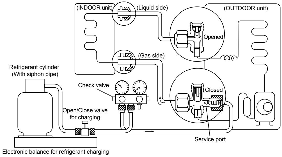
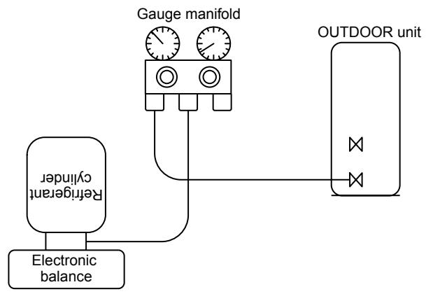
Fig. 6-4-1 Configuration of refrigerant charging
Be sure to make setting so that liquid can be charged.
When using a cylinder equipped with a siphon, liquid can be charged without turning it upside down.
It is necessary for charging refrigerant under condition of liquid because R410A is mixed type of refrigerant. Accordingly, when charging refrigerant from the refrigerant cylinder to the equipment, charge it turning the cylinder upside down if cylinder is not equipped with siphon.
[ Cylinder with siphon ]
[ Cylinder without siphon ]
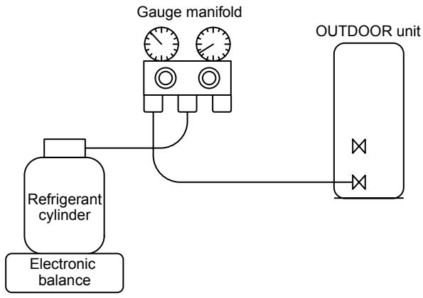
R410A refrigerant is HFC mixed refrigerant. Therefore, if it is charged with gas, the composition of the charged refrigerant changes and the characteristics of the equipment varies.
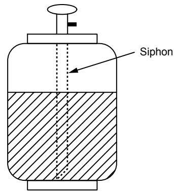
Fig. 6-4-2
6-5. Brazing of Pipes
6-5-1. Materials for Brazing
(1) Silver brazing filler
Silver brazing filler is an alloy mainly composed of silver and copper. It is used to join iron, copper or copper alloy, and is relatively expensive though it excels in solderability.
(2) Phosphor bronze brazing filler
Phosphor bronze brazing filler is generally used to join copper or copper alloy.
(3) Low temperature brazing filler
Low temperature brazing filler is generally called solder, and is an alloy of tin and lead. Since it is weak in adhesive strength, do not use it for refrigerant pipes.
- Phosphor bronze brazing filler tends to react with sulfur and produce a fragile compound water solution, which may cause a gas leakage. Therefore, use any other type of brazing filler at a hot spring resort, etc., and coat the surface with a paint.
- When performing brazing again at time of servicing, use the same type of brazing filler.
6-5-2. Flux
(1) Reason why flux is necessary
- By removing the oxide film and any foreign matter on the metal surface, it assists the flow of brazing filler.
- In the brazing process, it prevents the metal surface from being oxidized.
- By reducing the brazing filler's surface tension, the brazing filler adheres better to the treated metal.
(2) Characteristics required for flux
- Activated temperature of flux coincides with the brazing temperature.
2.Due to a wide effective temperature range, flux is hard to carbonize.
3.It is easy to remove slag after brazing. - The corrosive action to the treated metal and brazing filler is minimum.
5.It excels in coating performance and is harmless to the human body.
As the flux works in a complicated manner as described above, it is necessary to select an adequate type of flux according to the type and shape of treated metal, type of brazing filler and brazing method, etc.
(3) Types of flux
Noncorrosive flux
Generally, it is a compound of borax and boric acid.
It is effective in case where the brazing temperature is higher than 800^ .
Activated flux
Most of fluxes generally used for silver brazing are this type.
It features an increased oxide film removing capability due to the addition of compounds such as potassium fluoride, potassium chloride and sodium fluoride to the borax-boric acid compound.
(4) Piping materials for brazing and used brazing filler/flux
| Piping material | Used brazing filler | Used flux |
| Copper - Copper | Phosphor copper | Do not use |
| Copper - Iron | Silver | Paste flux |
| Iron - Iron | Silver | Vapor flux |
- Do not enter flux into the refrigeration cycle.
- When chlorine contained in the flux remains within the pipe, the lubricating oil deteriorates. Therefore, use a flux which does not contain chlorine.
- When adding water to the flux, use water which does not contain chlorine (e.g. distilled water or ion-exchange water).
- Remove the flux after brazing.
6-5-3. Brazing
As brazing work requires sophisticated techniques, experiences based upon a theoretical knowledge, it must be performed by a person qualified.
In order to prevent the oxide film from occurring in the pipe interior during brazing, it is effective to proceed with brazing while letting dry Nitrogen gas (N2) flow.
Never use gas other than Nitrogen gas.
(1) Brazing method to prevent oxidation
- Attach a reducing valve and a flow-meter to the Nitrogen gas cylinder.
- Use a copper pipe to direct the piping material, and attach a flow-meter to the cylinder.
- Apply a seal onto the clearance between the piping material and inserted copper pipe for Nitrogen in order to prevent backflow of the Nitrogen gas.
- When the Nitrogen gas is flowing, be sure to keep the piping end open.
- Adjust the flow rate of Nitrogen gas so that it is lower than 0.05 m^3/Hr or 0.02 MPa ( 0.2 kgf/cm^2 ) by means of the reducing valve.
- After performing the steps above, keep the Nitrogen gas flowing until the pipe cools down to a certain extent (temperature at which pipes are touchable with hands).
- Remove the flux completely after brazing.
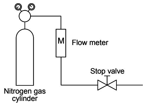
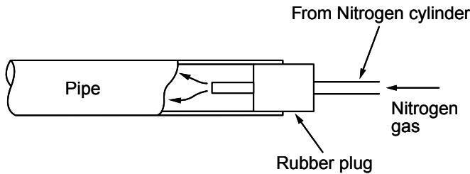
Fig. 6-5-1 Prevention of oxidation during brazing
7. INDOOR UNIT CONTROL
7-1. Indoor Control Circuit
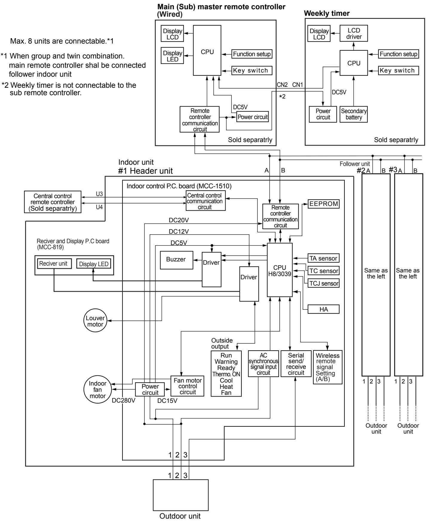
INDOOR UNIT CONTROL CIRCUIT (Continued)
7-2. Control Specifications
| NO. | Item | Overview of specifications | Remarks | |||
| 1 | Control at power-on reset | (1) Identification of outdoor unit Identifies outdoor unit at power-on reset, and switches control according to the identification result. (2) Setting of indoor unit fan speed and adjustment of air flow direction Switches indoor unit fan speed, setting of air flow direction adjustment, etc. based on EEPROM data. | The “PREPARING” lamp lights during initial setting (model recognition) after power-on reset. Fan speed, adjustment of air flow direction | |||
| 2 | Operation mode switching | (1) Switches operation mode according to mode select instruction from remote controller. | Ta: Room temperature Ts: Set temperature To: Outside air temperature | |||
| R/C instructions | Outline of control | |||||
| OFF | Turns OFF air conditioner | |||||
| FAN | “Fan only” operation | |||||
| COOL | Cooling operation | |||||
| DRY | Dehumidifying operation | |||||
| HEAT | Heating operation | |||||
| AUTO | • Selects COOL or HEAT mode automatically according to Ta, Ts, and To. • The first operation is as follows according to Ta. (COOL thermo sensor continues OFF (FAN mode with set fan speed) within the range of Ts +α-1<Ta< Ts+α-1.Ta(Tc)+1.0Tc+α-1.0FAN mode with set fan speed -FAN mode with set fan speed -FAN mode with set fan speed -FAN mode with set fan speed -FAN mode with set fan speed -FAN mode with set fan speed -FAN mode with set fan speed -FAN mode with set fan speed -FAN mode with set fan speed -FAN mode with set fan speed -FAN mode with set fan speed -FAN mode with set fan speed -FAN mode with set fan speed -FAN mode 18°C • α is corrected according to outside air temperature. | |||||
| Outside air temp. | Corrected value (α) | |||||
| No To | 0 K | |||||
| To≥24°C | -1 K | |||||
| 24>To≥18°C | 0 K | |||||
| To<18°C | +1 K | |||||
| Abnormal To | 0 K | |||||
| (2) Operation instruction permission mode HEAT and AUTO modes are not available for COOL only models. When instruction is issued from wireless remote controller in the HEAT or AUTO mode, it is indicated by a reception sound “pi, pi” and by alternate blinking of “TIMER” and “PREPARING” lamps. To cancel this alternate blinking, issue an instruction of mode other than HEAT or AUTO. | k=deg | |||||
| 3 | Room temperature control | (1) Adjustment range Remote controller set temperature (°C) | ||||
| COOL/DRY | HEAT | AUTO | ||||
| Wired type | 18 - 29 | 18 - 29 | 18 - 29 | |||
| Wireless type | 17 - 30 | 17 - 30 | 17 - 30 | |||
| * When use of remote controller sensor is set (with DN32), even when sensor value is within the above range in HEAT or AUTO mode, the thermo sensor turns OFF when Ta sensor value exceeds 35 °C. | ||||||
| NO. | Item | Overview of specifications | Remarks | ||||
| 3 | Room temperature control | (2) The set temperature for HEAT operation can be corrected by code No. 06. | Heat intake temperature shift (When unit's temperature sensor is used) | ||||
| Set data | 0 | 2 | 4 | 6 | |||
| Correction of set temp. | +0°C | +2°C | +4°C | +6°C | |||
| Factory setting | |||||||
| Set data | 2 | ||||||
| * When use of remote controller sensor is set (with DN32), no correction is performed. | |||||||
| 4 | Capacity auto control (GA control) | (1) Issues instruction of operating frequency to outdoor unit according to the difference between Ta and Ts. | |||||
| (2) COOL operationCalculates room temp. difference between Ta and Ts as well as room temp. variation every 90 seconds to find correction value of specified operating frequency and to correct the current operating frequency.Ta(n)-Ts(n) : Room temp. difference n : Number of detection times Ta(n-1)-Ta(n) : Room temp. variation n-1 : Number of detection times (90 seconds before) | |||||||
| (3) HEAT operationCalculates room temp. difference between Ta and Ts as well as room temp. variation every 60 seconds to find correction value of specified operating frequency and to correct the current operating frequency.Ts(n)-Ts(n) : Room temp. difference n : Number of detection times Ta(n)-Ta(n_1) : Room temp. variation n-1 : Number of detection times (60 seconds before) | |||||||
| (4) DRY operationThe frequency correction control is the same as that for COOL operation.However, the maximum frequency is limited to S6 or so.Note) When LOW fan speed is set, the maximum frequency is limited to SB or so. | |||||||
| 5 | COOL/HEAT/AUTO control | (1) Switching between COOL and HEAT is determined based on the following control. | Tsc: COOL set temp.Tshc: HEAT set temp. + room temp. control/correction | ||||
| Ta(°C)+1.5Tscor Tsh-1.5 | COOL(℃) | (℃)ON | After 10 minutes pass from thermo sensor OFF, operation mode changes from HEAT (thermo sensor OFF) to COOL if Ta exceeds Tsh +1.5.( ) shows an example of COOL ON/OFF.After 10 minutes pass from thermo sensor OFF, operation mode changes from COOL (thermo sensor OFF) to HEAT if Ta lowers below Tsc -1.5. | ||||
| (2) The GA control after determination of operation mode follows the description in No. 4. | |||||||
| (3) The room temperature control and temperature correction follow the descriptions in No. 3 and No. 15. | |||||||
INDOOR UNIT CONTROL CIRCUIT (Continued)
| NO. | Item | Overview of specifications | Remarks | |||||
| 6 | Fan speed control | (1) A fan speed HH (quick high), H (high), L (low) or AUTO is selected according to the instruction from remote controller for FAN mode operation. (2) Fan speed is switched according to the difference between Ta and Ts in the AUTO mode. | HH>H>>H> L>L>UL Wireless type allows HH, H+, H, L+, L, and AUTO. | |||||
| [Ta (°C)] +3.0 +2.5 +2.0 +1.5 +1.0 +0.5 Tsc -0.5 | A HH (HH) +2.5 +2.0 +1.5 +1.0 +0.5 L(H) L(H) L(L+) | B C D E F G | [H] [H+] [H] [L+] [L] | |||||
| · The fan speed control is the same for temperature setting by remote controller or the unit. · Once fan speed is changed, it remains unchanged for 3 minutes unless different fan speed is selected by instruction. · At the beginning of cooling, a falling gradient (higher fan speed) is selected. · When the temperature difference between Ta and Ts is on a threshold line, fan speed does not change. · ( ) : Auto cooling | ||||||||
| [Heating] Ta (°C) (-0.5) +1.0 (+0.5) +1.0 (+1.0) +2.0 (+1.5) +3.0 (+2.0) +4.0 | ||||||||
| ( ) : Temperature setting by remote controller Other than ( ) : Temperature setting by unit · Once fan speed is changed, it remains unchanged for one minute unless different fan speed is selected by instruction. · At the beginning of heating, a rising gradient (higher fan speed) is selected. · When the temperature difference between Ta and Ts is on a threshold line, fan speed does not change. · ( ) : Auto heating · Fan speed is switched to a higher level when Tc reaches 60 °C. | Tc : Indoor unit heat exchange sensor temp. | |||||||
| NO. | Item | Overview of specifications | Remarks | ||||
| 6 | Fan speed control | COOL | HEAT | AP40-56 | AP63 | AP71-80 | "HEAT PREPARED" indication |
| HH | 1220 | 1360 | 1480 | ||||
| HH | 1180 | 1300 | 1340 | ||||
| H+ | H+ | 1140 | 1240 | 1320 | |||
| H | 1120 | 1200 | 1300 | ||||
| H | 1060 | 1120 | 1200 | ||||
| L+ | 1060 | 1120 | 1200 | ||||
| L+ | L | 990 | 1020 | 1100 | |||
| L | 940 | 970 | 1040 | ||||
| UL | UL | 500 | 500 | 500 | |||
| (3) When thermo sensor turns OFF during heating, the fan speed mode becomes UL (weak). (4) When Ta is 25 °C or above at the beginning of HEAT operation or when canceling defrost mode, H or HH mode continues for one minute from the time when Tc enters zone E shown in the figure in No.7 below. (5) The HH fan speed for auto cooling/heating is set to a speed higher than that for normal cooling/heating. However, it varies depending on the temperature difference of Tc during auto heating. | |||||||
| Tc(°C)4742HH+α | |||||||
| 7 | Cool air prevention control | (1) Perform室内扇风控制在加热模式下,当扇风温度达到或超过50℃时,风机将自动停止。 Tc(Tcj)(°C)36HH34LZoneDOffZoneCZoneBZoneA | Fan speed select setting by remote controller takes precedence in zones D and E. "HEAT PREPARED" is indicated in zones A and B. | ||||
INDOOR UNIT CONTROL CIRCUIT (Continued)
| Item | Overview of specifications | Remarks | ||
| 8NO. | Freezing prevention control(low-temp.release) | (1)Performs the following operation control in the COOL or DRYmode according to the Tc (or Tcj) sensor detect temperature.When zone J in the figure below is detected for 6 minutes, the specified operating frequency is decreased from the actualoperating frequency, and the specified operating frequency is changed every 30 seconds in zone J.Timer count stops and is maintained in zone K.Timer count is cleared to restore normal operation when zone I isdetected.If the specified operating frequency becomes SO due tocontinuation of zone J, return temperature A is raised from 5 to12 °C, and operation with L fan speed continues until zone I isdetected. | Tcj: Indoor unit heatexchange sensortemp. | |
| If 4-way valve cannot be switched during heating and the followingconditions become true, freezing prevention control is performed.(However, zone J entering control temperature is changed from 2to -5 °C.)[Conditions]The following ① or ② becomes true after 5 minutes pass fromoperation start.① Tcn≤Tc(n-1)-5② Tcn<Tc(n-1)-1 and Tcn≤Ta<5°C | Tcn:Tc after 5 minutesfrom operation startTc (n-1):Tc at operation start | |||
| 9 | High-temp. releasecontrol | (1)Performs the following operation control in the HEAT modeaccording to the Tc (or Tcj) sensor detect temperature.When zone M is detected, the specified operating frequency isdecreased from the actual operating frequency, and the specifiedoperating frequency is changed every 30 seconds in zone M.The specified operating frequency is maintained in zone N.When zone L is detected, the specified operating frequency isreturned by approx. 6 Hz every 60 seconds.Factory settingControl temp. (°C)A B56 (54) 52 (52)Note) At the beginning of operation or when Tc (or Tcj) lowers below30 °C after operation start, values (54) and (52) in the table areused as control temperature. | This control is disabled fortwin follower indoor units. | |
| Even when the thermo isset to OFF, the control isimplemented in the same way. | ||||
| 10 | Residual heatremoval | Runs indoor unit fan in L (low) mode for about 30 seconds after HEAToperation stops to remove residual heat. | ||
| NO. | Item | Overview of specifications | Remarks | |
| 11 | Flap control | (1) During the first operation after power on, flap position is controlled automatically according to operation mode (COOL/HEAT). | Louver angle: 0 °C (full close) | |
| Cooling | Heating | Full close | ||
| 45° | 103° | 0° | ||
| (2) When Louver position is controlled by remote controller, the unit's microcomputer memorizes the position for use in the next operation. * The memorized Louver position is cleared when power is turned off, and returns to the state of (1) above. | Alarm : A code number (except F08 and L31) appears on the remote controller and the indoor unit stops. | |||
| (3) Flap position setting · Flap position can be set within the range below. COOL/DRY | HEAT/FAN | |||
| · Flap position can be set collectively or individually in the group twin or triple operation mode. (Wireless remote controller allows individual setting only.) | ||||
| (4) Swing setting · Flap moves within the range below. All operation modes | ||||
| · Flap swing range can be set collectively or individually in the group twin or triple operation mode. (Setting by wireless remote controller is disabled when the main remote controller is used.) | ||||
| (5) When air conditioner operation stops, flap closes automatically. It keeps its position in the event of an alarm. | ||||
| (6) Flap tilts upward automatically during preparation for heating. | ||||
| (7) In the twin or triple operation mode selected by wireless remote controller, swing setting interlocks with the header indoor unit. If this setting is transmitted from a follower indoor unit, operation does not change with a reception sound “pi, pi, pi” if operation mode differs between header unit and follower unit. | ||||
INDOOR UNIT CONTROL CIRCUIT (Continued)
| Item | Overview of specifications | Remarks | |
| 12NO. | HA control | (1) When connected to a remote control system (tele-control or remote on/off interface), operation ON/OFF can be controlled by the HA signal input.(2) Outputs operation ON/OFF status to the HA output terminal.(3) HA signal input/output specifications conform to the JEMA standard. | A connector (separately available) is required when using the HA terminal CH61 for remote ON/OFF control.When group operation is in use, connect the connector to either header or follower indoor unit. |
| 13 | Filter sign indication (unavailable for wireless type) | (1) Transmits filter replacement signal to remote controller for indication on the LCD when accumulated operation hours of indoor unit fan exceeds the specified time (150 hours).(2) Clears accumulation timer upon receiving the filter reset signal from remote controller. At this time, when the specified time has already passed, the accumulated time is reset and the filter sign disappears from the LCD. | “FILTER” lamp ON |
| NO. | Item | Overview of specifications | Remarks |
| 14 | Central control mode switching | (1) The scope of operation by remote controller on the indoor unit side can be switched by the setting of remote controller.(2) Scope of operation by remote controller on the indoor unit side [Individual] : All settings and ON/OFF operations are available.[Central 1] : ON/OFF operations are disabled.[Central 2] : ON/OFF operations, operation mode selection, and temperature setting are disabled.[Central 3] : Operation mode selection and temperature setting are disabled.[Central 4] : Operation mode selection is disabled. | No indication“CENTRAL CONTROL”lamp ON“CENTRAL CONTROL”lamp ON“CENTRAL CONTROL”lamp ON“CENTRAL CONTROL”lamp ONWhen wired remote controller is not used, operation range is the same as above though lamp indication remains unchanged.If an unavailable operation mode is transmitted from wireless remote controller, it is indicated with a reception sound “pi, pi, pi, pi, pi”. |
| 15 | Power-saving control | (1) Power-saving operation is available in the AUTO mode.(2) The set temperature is corrected using various sensor data within the range where comfort is maintained.(3) By using various sensor data including room temp. Ta, outside air temp. To, fan speed, and indoor unit heat exchange sensor temp. Tc, 20-minute data is averaged to calculate a set temperature correction value.(4) The set temperature is corrected every 20 minutes with the following shift range.Cooling: +1.5 to -1.0KHeating: -1.5 to +1.0K | |
| 16 | Maximum frequency limit control | (1) This control is performed when AUTO mode is selected.(2) COOL mode: When To is under 28 °C, the control is as follows.Ta(°C)+4+3TscMaximum frequency is limited to the rating of cooling.(3) HEAT mode: When To is over 15 °C, the control is as follows.Ta(°C)TshMaximum frequency is limited to the rating of heating.Normal control↓ |
INDOOR UNIT CONTROL CIRCUIT (Continued)
7-3. P.C. Board of Indoor Unit
MCC-1510
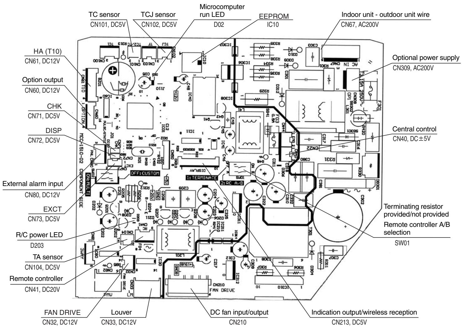
7-4. Optional Onboard Connector Specifications
| Function | Connector No. | Pin No. | Specification | Description |
| Terminating resistorRemote controller A/B | SW01 | Bit 1 | OFF: No terminating resistorON: Terminating resistor provided | Factory setting OFF: No terminating resistor ON for one unit when performing central control by custom air conditioner only. |
| Bit 2 | OFF: R/C A, ON: R/C B | Factory setting OFF: Remote controller A | ||
| Ventilation output | CN32 | ① | DC12V | Factory setting: Interlocking with indoor unit operation ON/OFF* Single operation setting is performed with VENT button on the remote controller (DN=31). |
| ② | Output | |||
| HA | CN61 | ① | ON/OFF input | HA ON/OFF input (J01: input/no input=pulse (factory setting) / static input changeover) |
| ② | OV (COM) | |||
| ③ | R/C prohibition input | Enables/disables operation OFF by remote controller using the R/C prohibition input. | ||
| ④ | Operation ON output | ON during operation (answerback of HA) | ||
| ⑤ | DC12V (COM) | |||
| ⑥ | Alarm output | ON during alarm | ||
| Option output | CN60 | ① | DC12V (COM) | |
| ② | Defrost output | ON while outdoor unit is defrosting | ||
| ③ | Thermo sensor ON output | ON when thermo sensor is ON (compressor ON) | ||
| ④ | COOL output | ON in cooling mode (COOL/DRY/auto cooling) | ||
| ⑤ | HEAT output | ON in heating mode (HEAT/auto heating) | ||
| ⑥ | FAN output | ON while indoor unit fan is ON | ||
| Externalalarm input | CN80 | ① | DC12V (COM) | Factory setting: External alarm input setting (DN: 2A=2)Indicates alarm code “L30” when an alarm continues for one minute and performs forcible operation OFF.(DN: 2A=1)Performs option alarm input control (indication of unit protection attached externally).* Remote control performs setting of option alarm input controller. |
| ② | DC12V (COM) | |||
| ③ | Filter/option/external alarm input | |||
| CHK Operationcheck | CN71 | ① | Check mode input | Used for checking indoor unit operation. (Outputs specified operations such as indoor unit fan speed H, without communication with outdoor unit or remote controller.) |
| ② | OV | |||
| DISP DISP mode | CN72 | ① | Display mode input | DISP mode enables communication only between indoor unit and remote controller. (at power on)Timer short-circuited (always) |
| ② | OV | |||
| EXCT Demand | CN73 | ① | Demand input | Turns OFF indoor unit thermo sensor forcibly. |
| ② | OV |
8. Troubleshooting
1. Guide to Troubleshooting
[Wired Remote Controller Type]
(1) Before starting troubleshooting
(a) Necessary tools/measuring equipment
- Phillips screwdrivers, flat-blade screwdrivers, wrenches, pliers, nipper, etc.
- Multimeter, thermometer, pressure gauge, etc.
(b) Precheck
(1) The following operations are normal.
1) Compressor does not work.
- Is 3-minute delay operation functioning? (for 3 minutes after compressor OFF)
Is thermo sensor OFF? - Is FAN mode or TIMER mode operation going?
- Is water overflow alarm detected?
- Is high outside air temperature operation control working during heating?
2) Indoor unit fan does not work.
- Is cool air prevention control working during heating?
3) Outdoor unit fan does not work or its fan speed changes.
- Is high-temp. release operation control working during heating?
- Is low outside air temperature operation control working during cooling?
- Is defrosting operation going?
4) Operation ON/OFF by remote controller is disabled.
- Is any remote controller or external control working?
- Is auto address setting in progress?
(At the first power on or when indoor unit address is changed, operation control is disabled for about 5 minutes after power on.)
(2) Are all cables/wiring set in the initial state?
③ Are indoor unit and remote controller connected correctly?
(2) Troubleshooting procedure
When an error occurs, check the unit in the following procedure.
Error Check indication of check code Check faulty location and parts
(Note) Other than the check items in the table, malfunction or wrong diagnosis of microcomputer due to effect of power or external noise is considered. If there is any source of noise, shield the remote controller wiring.
[Wireless Remote Controller Type]
(1) Before starting troubleshooting
(a) Necessary tools/measuring equipment
- Phillips screwdrivers, flat-blade screwdrivers, wrenches, pliers, nipper, etc.
- Multimeter, thermometer, pressure gauge, etc.
(b) Precheck
(1) The following operations are normal.
1) Compressor does not work.
- Is 3-minute delay operation functioning? (for 3 minutes after compressor OFF)
- Is thermo sensor OFF?
- Is FAN mode or TIMER mode operation going?
- Is high outside air temperature operation control working during heating?
2) Indoor unit fan does not work.
- Is cool air prevention control working during heating?
3) Outdoor unit fan does not work or its fan speed changes.
- Is high-temp. release operation control working during heating?
- Is low outside air temperature operation control working during cooling?
- Is defrosting operation going?
4) Operation ON/OFF by remote controller is disabled.
- Is forcible operation OFF mode set?
- Is any remote controller or external control working?
- Is auto address setting in progress?
(At the first power on or when indoor unit address is changed, operation control is disabled for about 5 minutes after power on.)
(2) Are all cables/wiring set in the initial state?
③ Are indoor unit and receiver unit connected correctly?
(2) Troubleshooting procedure
When an error occurs, check the unit in the following procedure.
Error Check indication of lamps Check faulty location and parts
(Note) Other than the check items in the table, malfunction or wrong diagnosis of microcomputer due to effect of power or external noise is considered. If there is any source of noise, shield the signal lines.
(a) Outline of judgment
The following describes the primary judgment of locating faulty unit (indoor unit or outdoor unit). (In the case of group control operation, the header unit also indicates errors of follower unit by lamp.)
Judging from lamp status of indoor unit
The indoor unit monitors the operating status of air conditioner. When the protection circuit is activated, the indoor unit indicates the following self-diagnosis contents.
OFF ON Blinking (0.5 seconds interval)
| Lamp indication | Check code | Possible causes |
| OPERATION TIMER PREPAREDAll OFF | - | Power OFFPoor connection/contact between receiver/indication unit and indoor unit control board |
| OPERATION TIMER PREPAREDBlinking | E01 | Reception error(Wired remote Transmission error) controllerWrong connection or poor contact between Communication errorwired remote controller and indoor unit |
| E02 | ||
| E03 | ||
| E08 | Duplication of indoor unit No.Invalid setting | |
| E09 | ||
| E18 | Poor connection/contact between indoor units or indoor unit power OFF(Communication error between header and follower indoor units or between twin header and follower indoor units) | |
| OPERATION TIMER PREPAREDBlinking | E04 | Wrong connection or poor contact between indoor unit and outdoor unit(Communication error between indoor and outdoor units) |
| OPERATION TIMER PREPAREDAlternate blinking | P12 | Failure of indoor unit DC fan (Protection device of indoor unit is activated.) |
Troubleshooting (Continued)
Outline of judgment (Continued)
| Lamp indication | Check code | Possible causes |
| OPERATION TIMER PREPARINGAlternate blinking | P03 | Abnormal outdoor unit discharge temperature (°) Protection device of outdoor unit is activated. |
| P04 | Outdoor unit high-pressure system error activated. | |
| P19 | Four-way valve system error (judged by indoor unit) | |
| P22 | Outdoor unit: Malfunction of fan Protection device of outdoor unit is activated. | |
| P26 | ||
| P29 | ||
| P31 | Header and follower indoor units in the group are not running due to the following alarm. (Alarm code: E03, L03, L07, L08) | |
| OPERATION TIMER PREPARINGAlternate blinking | F01 | Heat exchange sensor (TCJ) error Indoor unit sensor error |
| F02 | ||
| F10 | Heat exchange sensor (TC) error Room temperature sensor (TA) error | |
| OPERATION TIMER PREPARINGAlternate blinking | F04 | Discharge temperature sensor (TD) error Temperature sensor (TE, TS) error (°) Outdoor unit sensor error |
| F06 | ||
| F08 | ||
| OPERATION TIMER PREPARINGSimultaneous blinking | F29 | Failure of indoor unit EEPROM |
| OPERATION TIMER PREPARINGBlinking | H01 | Compressor breakdown (°) Outdoor unit compressor system error |
| H02 | ||
| H03 | ||
| H06 | ||
| OPERATION TIMER PREPARINGSimultaneous blinking | L03 | Duplication of header indoor unit Group connection indoor unit for Auto address *If group configuration or address at power on is invalid, the unit enters address setting mode automatically. |
| L07 | ||
| L08 | ||
| L09 | ||
| No setting (indoor unit capacity) | ||
| OPERATION TIMER PREPARINGSimultaneous blinking | L20 | Duplication of indoor unit collective address Others |
| L29 | ||
| L30 | ||
| L31 |
(*) Check code detected by outdoor unit is a typical example. It varies with outdoor unit of combination.
For details, see the Service Guide of applicable outdoor unit.
Others (Excluding check code)
| Lamp indication | Check code | Possible causes |
| OPERATION TIMER PREPARING Simultaneous blinking | - | Trial operation in progress |
| OPERATION TIMER PREPARING Alternate blinking | - | Invalid setting (Auto cooling/heating setting for auto cooling/heating unavailable unit or heating setting for cool only unit) |
Error mode detected by remote controller or central controller
| Diagnosis function | Judgment and action | |||
| Check code | Possible causes | Air conditioner status | Conditions | |
| No indication (remote controller disabled) | No communication with header indoor unit Remote controller is not connected correctly. Indoor unit is not powered on. Auto address setting is not completed. | OFF | - | Failure of remote controller power supply or indoor unit EEPROM1. Check remote controller wires.2. Check remote controller.3. Check indoor unit power wiring.4. Check indoor unit P. C. board.5. Check indoor unit EEPROM and insertion into socket.... Auto address repetition occurs. |
| E01*2 | No communication with header indoor unit Disconnection between remote controller and header indoor unit (detected by R/C) | OFF (auto reset)*Operation continues under central control | Indicated when an error is detected | Remote controller signal reception error1. Check remote controller wires.2. Check remote controller.3. Check indoor unit power wiring.4. Check indoor unit P. C. board. |
| E02 | Signal transmission error to indoor unit (detected by R/C) | OFF (auto reset)*Operation continues under central control | Indicated when an error is detected | Remote controller transmission error1. Check remote controller transmitter.... Replace remote controller. |
| E09 | Multiple remote controller headers (detected by R/C) | OFF (Follower R/C continues operation) | Indicated when an error is detected | 1. Check for multiple remote controller headers.... One header only, others are follower R/C. |
| L20Central controller L20 | Duplication of indoor unit collective address during communication of central control system (detected by indoor unit/central controller) | OFF (auto reset) | Indicated when an error is detected | 1. Check central control network address setting. |
| *-3Central controller (Transmission) C05 (Reception) C06 | Failure of central control communication circuit (detected by central controller) | Operation continues (following R/C) | Indicated when an error is detected | 1. Check communication line, wrong connection, and indoor unit power supply.2. Check communication circuit (U3, U4, XY terminals).3. Check central controller (including central control R/C).4. Check terminating resistors (TCC-LINK). |
| -Central controller P30/b7 | Failure of indoor unit group follower unit. | Continue/OFF (depending on situation) | Indicated when an error is detected | Check the unit's check code with remote controller |
2 No check code can be indicated by wired remote controller. (Normal operation of air conditioner cannot be controlled by wired remote controller.) Check codes are indicated by the lamps for wireless models.
3 This is an error related to communication of remote controller (A, B) or central control system (TCC-LINK U3, U4). Remote controller indicates E01, E02, E03, E09, E18 or no code according to situation.
(Detected by indoor unit)
| Check code | Lamp indication | Main faulty location | Description of failures | A/C operation | |||
| TCC-LINK central control and remote controller | Block indication | Auto reset | Operation continuation | ||||
| OPERATION | TIMER | PREPARING | Blinking | ||||
| E03 | ○ | ○ | ○ | Indoor unit - R/C communication error | No signal from remote controller (no communication with central controller system) | ○ × | |
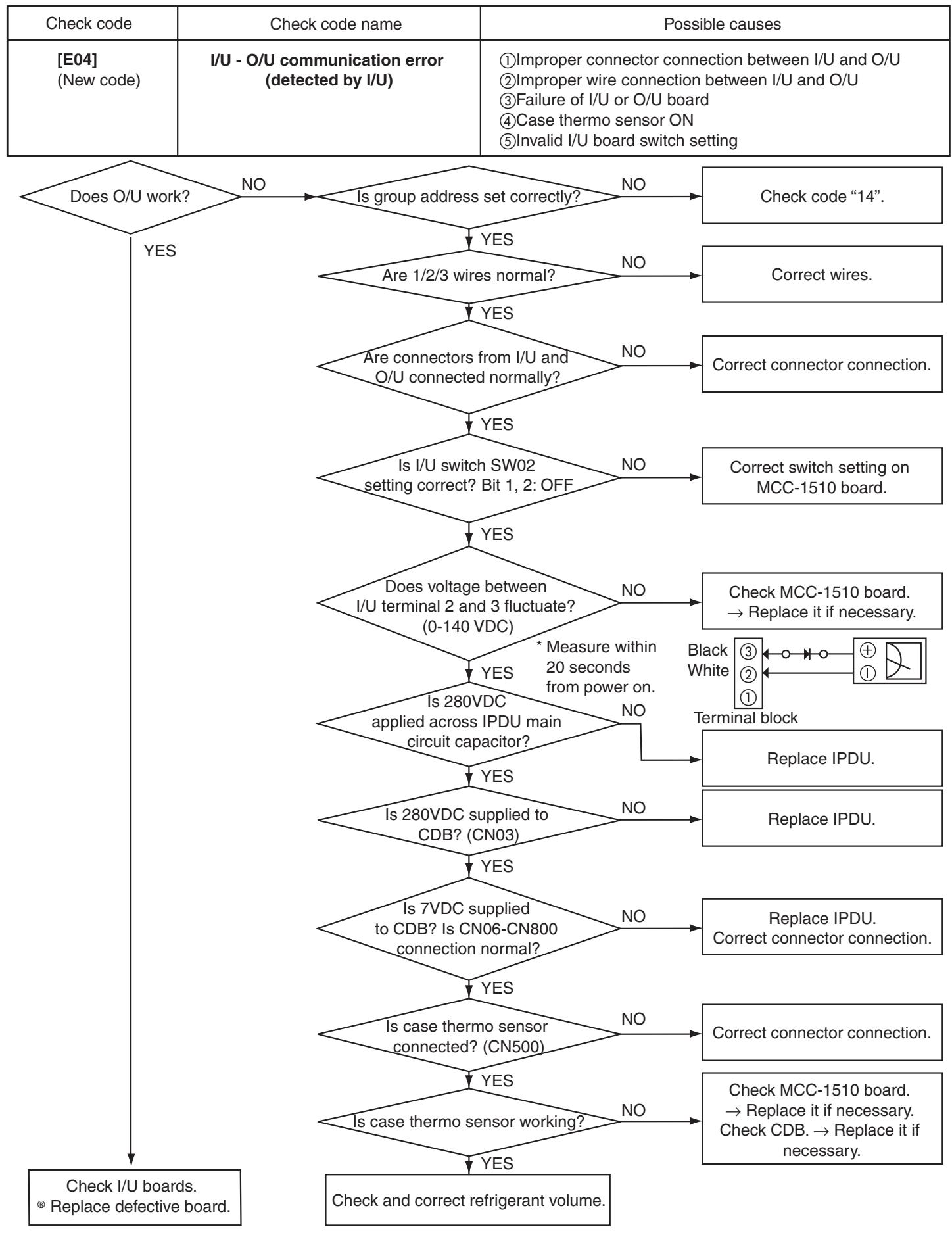
| E04 | ○ | ○ | ○ | Indoor unit - out door unit serial communication error | When indoor unit - out door unit serial communication is abnormal | ○ × | |
| E08 | ○ | ○ | ○ | Duplication of indoor unit address ☆ | When same address as mine is detected | ○ × | |
| E10 | ○ | ○ | ○ | Communication error between indoor unit MCUs | When communication between main motor microcomputers is abnormal | ○ × | |
| E18 | ○ | ○ | ○ | Communication error between header and follower indoor units | When communication between header and follower indoor units is disabled | ○ × | |
| F01 | ○ | ○ | ○ | Alternate | Indoor unit heat exchange sensor TCJ | When open-circuit or short-circuit of TCJ is detected | ○ × |
| F02 | ○ | ○ | ○ | Alternate | Indoor unit heat exchange sensor TC | When open-circuit or short-circuit of TC is detected | ○ × |
| F10 | ○ | ○ | ○ | Alternate | Indoor unit room temp. sensor TA | When open-circuit or short-circuit of TA is detected | ○ × |
| F29 | ○ | ○ | ○ | Simultaneous | Indoor unit other boards | Failure of EEPROM (Other errors are also detected in some cases. Auto address repeated with no other errors.) | × × |
| L03 | ○ | ○ | ○ | Simultaneous | Duplication of indoor group header unit setting ☆ | When multiple header units exist in the group | × × |
| L07 | ○ | ○ | ○ | Simultaneous | Group line in individual indoor unit ☆ | When there is at least one group connection indoor unit in individual indoor unit | × × |
| L08 | ○ | ○ | ○ | Simultaneous | Indoor group address not set ☆ | When indoor group address is not set | × × |
| L09 | ○ | ○ | ○ | Simultaneous | Indoor unit capacity not set | Indoor unit capacity is not set. | × × |
| L20 | ○ | ○ | ○ | Simultaneous | Duplication of central control refrigerant line address | Duplicated central control refrigerant line address is set. | ○ × |
| L30 | ○ | ○ | ○ | Simultaneous | External alarm input into indoor unit (interlock) | Alarm stop by external alarm input (CN80) | × × |
| P01 | ○ | ○ | ○ | Alternate | Indoor unit AC fan | When indoor unit AC fan alarm is detected (Fan motor thermal relay is activated.) | × × |
| P10 | ○ | ○ | ○ | Alternate | Indoor unit water overflow | When float switch is turned on | × × |
| P12 | ○ | ○ | ○ | Alternate | Indoor unit DC fan | When indoor unit DC fan alarm (overcurrent, locking, etc.) is detected | × × |
| P19 | ○ | ○ | ○ | Alternate | Four-way valve system | When an alarm is detected during heating due to temperature drop of heat exchange sensor | ○ × |
| P31 | ○ | ○ | ○ | Alternate | Other indoor unit errors | Follower units in the group are disabled due to alarm (E03/L03/L07/L08) of header unit | ○ × |
(Detected by remote controller)
:When this alarm is detected before checking group configuration and address at power on, the unit enters auto address setting mode automatically.
| Check code | Lamp indication | Main faulty location | Description of failures | A/C operation | |||
| Remote controller | Block indication | Auto reset | Operation continuation | ||||
| OPERATION | TIMER | PREPARING | Blinking | ||||
| E01 | ◎ | ● | ● | No header R/C, R/C reception error | When signals cannot be received from indoor unit or when header R/C is not set (including two R/Cs) | - | |
| E02 | ◎ | ● | ● | R/C transmission error | When signal transmission to indoor unit is disabled | - | |
| E09 | ◎ | ● | ● | Duplication of header R/C | When two remote controllers are set as header by double R/C control (Header unit stops alarm, and follower continues operation.) | × | |
(Detected by central controller)
| Check code | Lamp indication | Main faulty location | Description of failures | A/C operation | ||
| TCC-LINK central control | Block indication | Auto reset | Operation continuation | |||
| OPERATION TIMER PREPARED | Blinking | |||||
| C05 | No indication (when R/C is used together) | Central control system transmission error | When transmission of central control signals is disabled or when there are multiple central controllers with same address (AI-NET) | - | - | |
| C06 | Central control system reception error | When signal transmission to indoor unit is disabled | - | - | ||
| C12 | - | General equipment control I/F total alarm | A device connected to general equipment control interface (for TCC-LINK/AI-NET only) is abnormal. | - | - | |
| P30 | Depends on alarm No. above | Group follower unit error | Group follower unit is abnormal. (R/C indicates unit No. and details.) | - | - | |
Note: Check code varies in some cases depending on the unit which detects errors even if its content is the same.
ON, Blinking, OFF, Alternate: Two LEDs blink alternately, Simultaneous: Two LEDs blink simultaneously
(Main errors detected by outdoor unit)
| Check code | Lamp indication | Main faulty location | Description of failures | A/C operation | |||
| TCC-LINK central control and remote controller | Block indication | Auto reset | Operation continuation | ||||
| OPERATION | TIMER | PREPARING | Blinking | ||||
| C15 | ● | ○ | ○ | Simultaneous | Thermal storage unit error | Typical error of thermal storage unit (Details are checked by R/C.) | × × |
| F04 | ○ | ○ | ○ | Alternate | Outdoor unit heat discharge sensor TD error | When open-circuit or short-circuit of TD is detected | × × |
| F06 | ○ | ○ | ○ | Alternate | Outdoor unit temp. sensor TE, TS error | When open-circuit or short-circuit of TE,TS is detected | × × |
| F08 | ○ | ○ | ○ | Alternate | Outdoor unit outside air temp. sensor TO error | When open-circuit or short-circuit of TO is detected | ○ × |
| H01 | ● | ○ | ● | Compressor breakdown | Short-circuit current Idc after direct current excitation is detected when reaching minimum frequency in current release control. | × × | |
| H02 | ● | ○ | ● | Compressor locking | When compressor locking is detected | × × | |
| H03 | ● | ○ | ● | Current detect circuit error | When abnormal current is detected by AC-CT or when phase loss is detected | × × | |
| H06 | ● | ○ | ● | Low-pressure system error | Ps pressure sensor error. Low-pressure protection circuit is activated. | × × | |
| L29 | ○ | ○ | ○ | Simultaneous | Other outdoor unit errors | Other outdoor unit errors 1) MCU communication error between PDU and CDB, 2) IGBT heatsink temp. detect error | × × |
| L31 | ○ | ○ | ○ | Simultaneous | Phase sequence error or others | When phase sequence of 3-phase current is abnormal (thermo sensor OFF operation continued) or other errors | × △ |
| P03 | ○ | ● | ○ | Alternate | Abnormal outdoor unit discharge temperature | When discharge temperature release control detects an error | × × |
| P04 | ○ | ● | ○ | Alternate | High-pressure system error | When high-pressure switch or IOL is activated or when high-pressure release control by TE detects an error | × × |
| P22 | ○ | ● | ○ | Alternate | Outdoor unit fan alarm | When outdoor unit fan drive circuit error (overcurrent, locking, etc.) is detected | × × |
| P26 | ○ | ● | ○ | Alternate | Inverter Idc activated | When short-circuit prevention control for compressor drive circuit devices (G,Tr, IGBT) is activated | × × |
| P29 | ○ | ● | ○ | Alternate | Position detect error | When compressor motor position error is detected | × × |
Note: The above check codes are typical examples. They vary with outdoor unit (including thermal storage unit) of combination. For details, see the Service Guide of applicable outdoor unit.
Troubleshooting (Continued)
Check Code Table
Failure mode detected by indoor unit
| Diagnosis function | Judgment and action | |||
| Check code | Possible causes | Air conditioner status | Conditions | |
| E03 | No signal reception from remote controller | OFF (auto reset) | Indicated when an error is detected | 1. Check remote controller wiring. · No indication on remote controller LCD (disconnection) · Central controller [C06] check code |
| E04 | Serial signal from outdoor unit does not reach indoor unit. · Wrong wire connection · Failure of outdoor unit serial transmitter · Failure of indoor unit serial receiver | OFF (auto reset) | Indicated when an error is detected | 1. When outdoor unit does not work at all · Check wires, correct wrong connection. · Check outdoor unit boards and wiring. 2. When outdoor unit works normally Check boards (indoor unit receiver, outdoor unit transmitter) |
| E08 | Duplication of indoor unit address | OFF | Indicated when an error is detected | 1. Check remote controller connection (group/individual) change after power on. * If group configuration or address is not correct, the unit enters auto address setting mode automatically for address re-setting. |
| L03 | Duplication of header indoor unit | |||
| L07 | Group line in individual indoor unit | |||
| L08 | Indoor unit group address not set | |||
| L09 | Indoor unit capacity not set | OFF | Indicated when an error is detected | 1. Set indoor unit capacity (DN=11) |
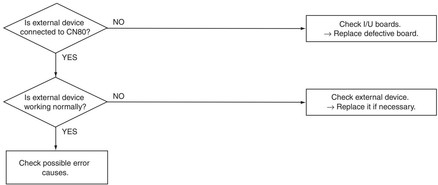
| L30 | External interlock alarm input | OFF | Indicated when an error is detected | 1. Check external devices. 2. Check indoor unit boards. |
| P12 | Failure of indoor unit DC fan | OFF | Indicated when an error is detected | 1. Position detect error 2. Overcurrent protection circuit operation of indoor unit fan driver 3. Indoor unit fan lock 4. Check indoor unit boards. |
| P19 | Failure of 4-way valve system · Indoor unit heat exchange temperature lowers after HEAT operation starts. | OFF (auto reset) | Indicated when an error is detected | 1. Check 4-way valve. 2. Check 2-way valve/check valve. 3. Check indoor unit heat exchanger (TC/TCJ). 4. Check indoor unit boards. |
| P31 | Indoor unit OFF during alarming to other indoor units | OFF (follower units) ( auto reset) | Indicated when an error is detected | 1. Judging follower unit when header unit is E03, L03, L07 or L08 2. Check indoor unit boards. |
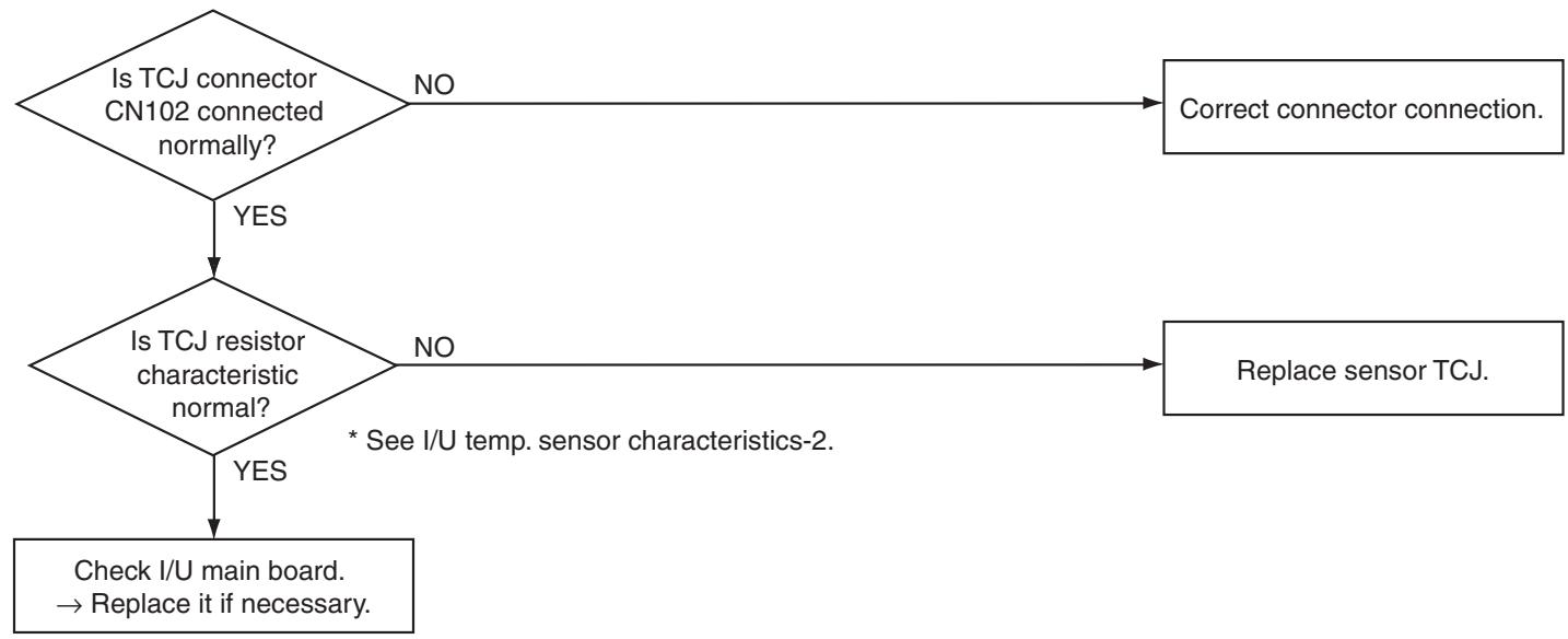
| F01 | Improper mounting, disconnection or short-circuit of indoor unit heat exchange sensor TCJ | OFF (auto reset) | Indicated when an error is detected | 1. Check TCJ. 2. Check indoor unit boards. |
| F02 | Improper mounting, disconnection or short-circuit of indoor unit heat exchange sensor TC | OFF (auto reset) | Indicated when an error is detected | 1. Check TC. 2. Check indoor unit boards. |
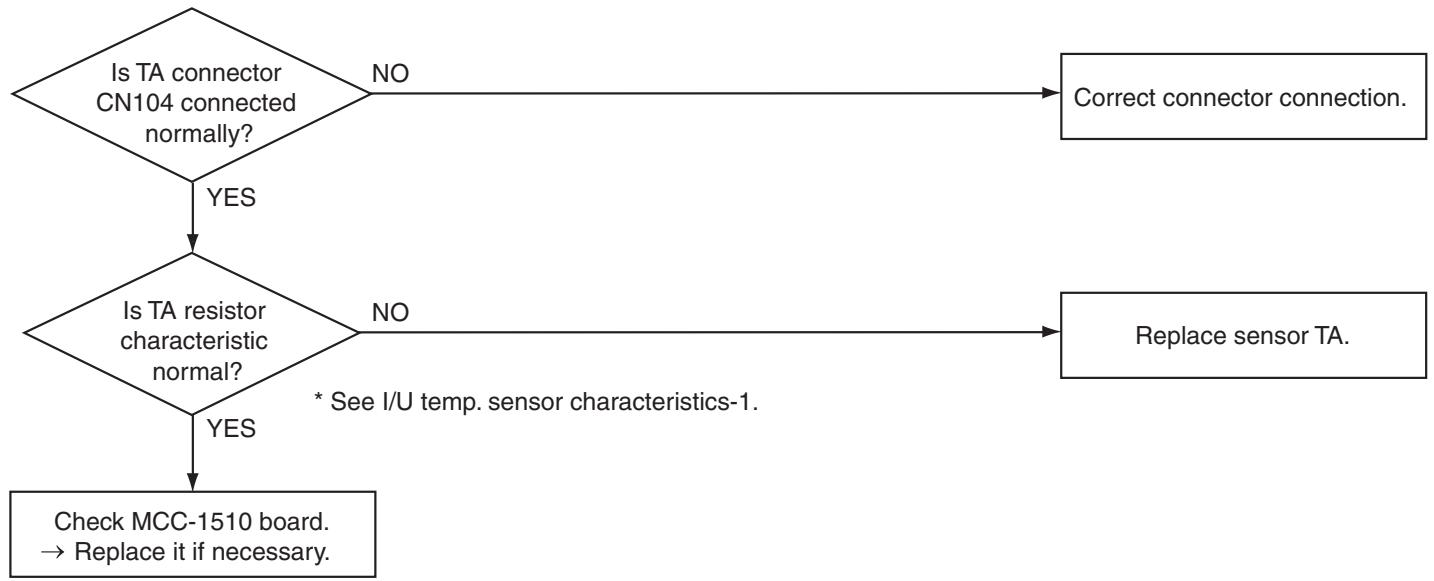
| F10 | Improper mounting, disconnection or short-circuit of indoor unit room temp. sensor TA | OFF (auto reset) | Indicated when an error is detected | 1. Check TA. 2. Check indoor unit boards. |
| F29 | Failure of indoor unit EEPROM · EEPROM access error | OFF (auto reset) | Indicated when an error is detected | 1. Check indoor unit EEPROM and insertion into socket. 2. Check indoor unit boards. |
| E18 | Communication error between header and follower indoor units | OFF (auto reset) | Indicated when an error is detected | 1. Check remote controller wiring. 2. Check indoor unit power wiring. 3. Check indoor unit boards. |
Failure mode detected by outdoor unit (Representative codes)
- The check code used varies depending on the combination with the outdoor unit.
| Diagnosis function | Judgment and action | |||
| Check code | Possible causes | Air conditioner status | Conditions | |
| H01 | Compressor breakdown • Compressor stops due to operating frequency decrease. | OFF | Indicated when an error is detected | 1. Check power voltages (200±20 VAC). 2. Freezing cycle overload operation 3. Check current detect circuit on the AC side. |
| H02 | Compressor does not work. • Overcurrent protection circuit is activated after a certain time from compressor startup. | OFF | Indicated when an error is detected | 1. Failure of compressor (lock, etc.) ... Replace the compressor. 2. Improper compressor wiring (phase loss) 3. Lost-phase operation of power supply (3-phase models) |
| H03 | Failure of current detect circuit • Large AC current even during compressor OFF • Phase loss in power supply | OFF | Indicated when an error is detected | 1. Operation stops soon when restarted. ... Check IPDU. 2. Lost-phase operation of power supply Check 3-phase power voltages and wiring. |
| H06*1 | Low-pressure switch ON (applicable models) COOL:30 seconds HEAT:10 minutes | OFF | Indicated when an error is detected | 1. Check freezing cycle (gas leakage). 2. Check low-pressure switch circuit. 3. Check outdoor unit CDB board. |
| L29 | Other outdoor unit errors • CDB-IPDU communication error (connector disconnection) • Abnormal heatsink temperature (over specified value) | OFF | Indicated when an error is detected | 1. Check CDB/IPDU wiring. 2. Freezing cycle overload operation |
| L31*1 | Phase detection protection circuit activated (normal models) | Operation continued (compressor OFF) | Indicated when an error is detected | 1. Check phase sequence, reverse phase, and phase loss. 2. Check outdoor unit boards. 3. Check high-pressure switch. 4. Check high-pressure switch circuit wiring. |
| P03 | Abnormal discharge temperature (over specified value) | OFF | Indicated when an error is detected | 1. Check freezing cycle (gas leakage). 2. Failure of electronic expansion valve 3. Check piping sensor (Td). |
| P04 | Failure of high-pressure protection circuit (Temperature over specified value detected by TE sensor) High-pressure switch (normal models) | OFF | Indicated when an error is detected | 1. Freezing cycle overload operation 2. Check outdoor unit TE sensor. 3. Check outdoor unit CDB board. 4. Check high-pressure switch and circuit. |
| P22 | Failure of outdoor unit DC fan | OFF | Indicated when an error is detected | 1. Position detect error 2. Overcurrent protection circuit operation of outdoor unit fan driver 3. Outdoor unit fan lock 4. Check outdoor unit CDB board. |
| P26 | Inverter overcurrent protection circuit activated (short time) Main circuit short voltage operation | OFF | Indicated when an error is detected | 1. Operation stops soon when restarted. ... Compressor partial short-circuit 2. Check IPDU for improper wiring. |
| P29 | Failure of IPDU position detect circuit | OFF | Indicated when an error is detected | 1. The circuit is activated even after compressor's 3P connector is disconnected. ...Replace IPDU. |
| F04 | Improper mounting, disconnection or short-circuit of outdoor unit temp. sensor TD | OFF | Indicated when an error is detected | 1. Check TD. 2. Check outdoor unit CDB board. |
| F06 | Improper mounting, disconnection or short-circuit of outdoor unit temp. sensor TE, TS | OFF | Indicated when an error is detected | 1. Check TE, TS. 2. Check outdoor unit CDB board. |
| F08 | Improper mounting, disconnection or short-circuit of outdoor unit outside air temp. sensor TO | Operation continued | Indicated when an error is detected | 1. Check TO. 2. Check outdoor unit CDB board. |
1 ROA-P** is not detected by 1HS models.
Fan continues rotating in a failure mode detected by outdoor unit because there is no communication between outdoor unit and follower indoor unit in twin group.
Troubleshooting (Continued)
2. Troubleshooting by Remote Controller Check Indication
Main Remote Controller (RBC-AMT31E)
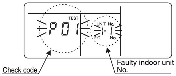
(1) Checking
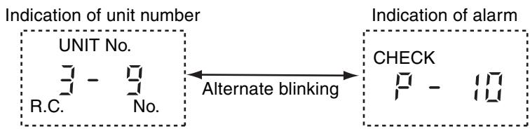
When an error occurs in the air conditioner, a check code and an indoor unit number appear on the LCD of remote controller.
Check code is displayed only during operation.
If indication disappears, check errors following
"Checking Error Log" below.
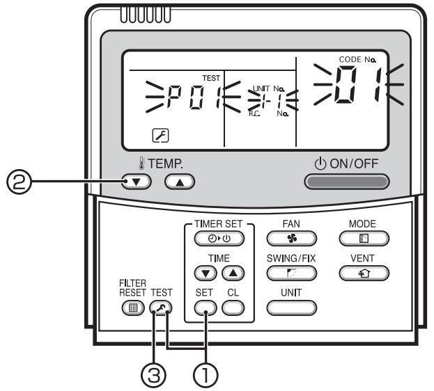
(2) Checking Error Log
When an error occurs in the air conditioner, error log can be checked following the steps below. Up to 4 errors are memorized.
Error log can be checked in both operation ON and OFF states.
| Step | Operation |
| ① | Press [SET] and [TEST] at the same time for 4 seconds or more. The LCD indication changes as shown below. Indication of “SERVICE CHECK” shows that the unit is in the error log mode. • Code No. “01” (order of error log) is displayed. • A check code is displayed. • The address of faulty indoor unit is displayed in the UNIT No. area. |
| ② | Each pressing of TEMP. Δ/∇ buttons displays stored error log sequentially. Check code “01” shows the latest error, and “04” shows the oldest. Note Do not press [CL] as this button clears entire error log of indoor unit. |
| ③ | After checking the error log, press [TEST] to return to the normal indication. |
Numbers appearing on the LCD
Hexadecimal number
TCC-LINK Central Control Remote Controller (TCB-SC642TLE)
(1) Checking
When an error occurs in the air conditioner, a check code and an indoor unit number appear on the LCD of remote controller.
Check code is displayed only during operation.
If indication disappears, check errors following
"Checking Error Log" below.

(2) Checking Error Log
When an error occurs in the air conditioner, error log can be checked following the steps below. Up to 4 errors are memorized.
Error log can be checked in both operation ON and OFF states.
① Press [SET] and [TEST] at the same time for 4 seconds or more.
② Indication of “SERVICE CHECK” and UNIT No. “01” appear.
③ When selecting a group number (blinking), a unit number and the latest error log, if any, are displayed alternately.
- Temperature setting is disabled at this time.
(4) To check other errors, choose a code (01 to 04) with TEMP. / buttons.
⑤ To check error log of another group, choose a group number with buttons.
Do not press [CL] as this button clears entire error log of the selected group.
⑥ Press [TEST] to finish the service check.
Troubleshooting (Continued)
- Troubleshooting for Each Check Code
| Check code | Check code name | Possible causes |
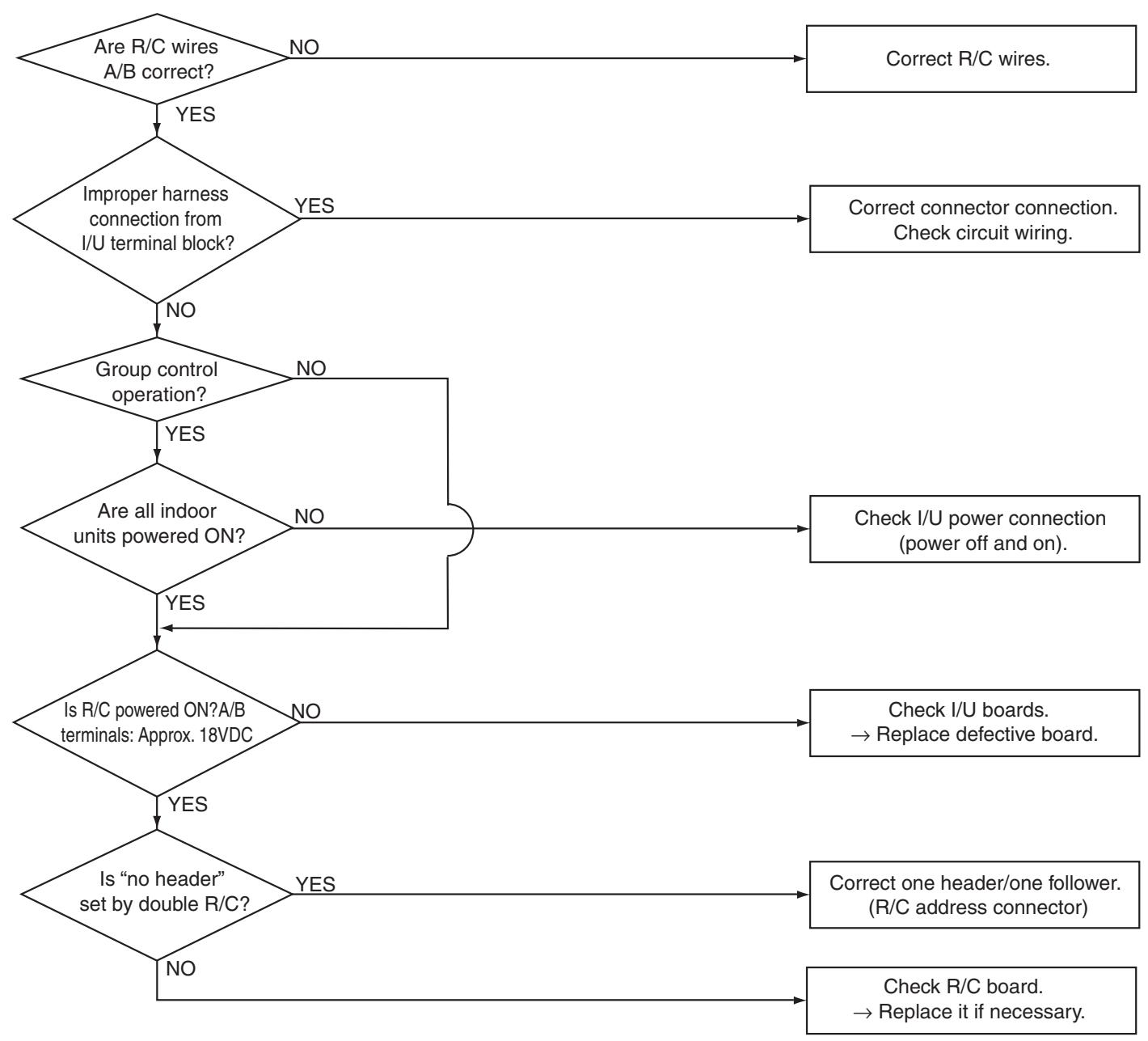
| [E01] (New code) | I/U - R/C communication error (detected by R/C) | ①Improper R/C wire connection ②Failure of I/U power supply ③Failure of I/U board ④Invalid R/C address setting ⑤Failure of R/C board |
| Check code | Check code name | Possible causes |
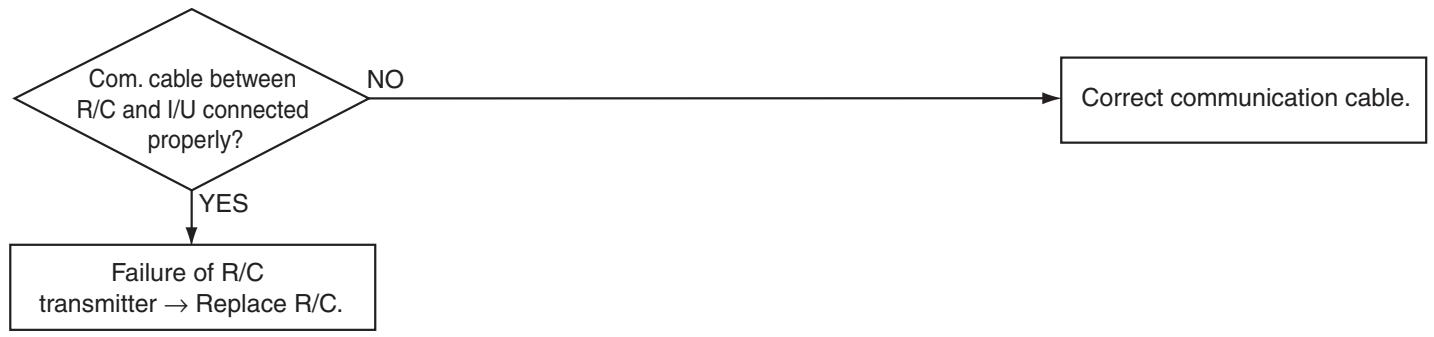
| [E02] (New code) | R/C transmission error | Signal transmission to indoor unit is disabled. |
- Not indicated on the central controller and outdoor unit 7-segment.
| Check code | Check code name | Possible causes |
| [E03] (New code) | I/U - R/C communication error (detected by I/U) | No communication from R/C and communication adapter. |
Indoor unit (I/U) detects this error when it cannot receive signals from remote controller (R/C).
Check communication wiring of R/C A and B.
This code E03 is not displayed on the R/C because of communication error.
This code is displayed on the TCC-LINK central controller.
Troubleshooting (Continued)
| Check code | Check code name | Possible causes |
| [E09] (New code) | Duplication of R/C header | R/C header setting is duplicated. |
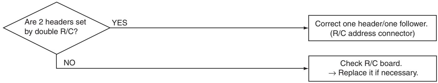
| Check code | Check code name | Possible causes |
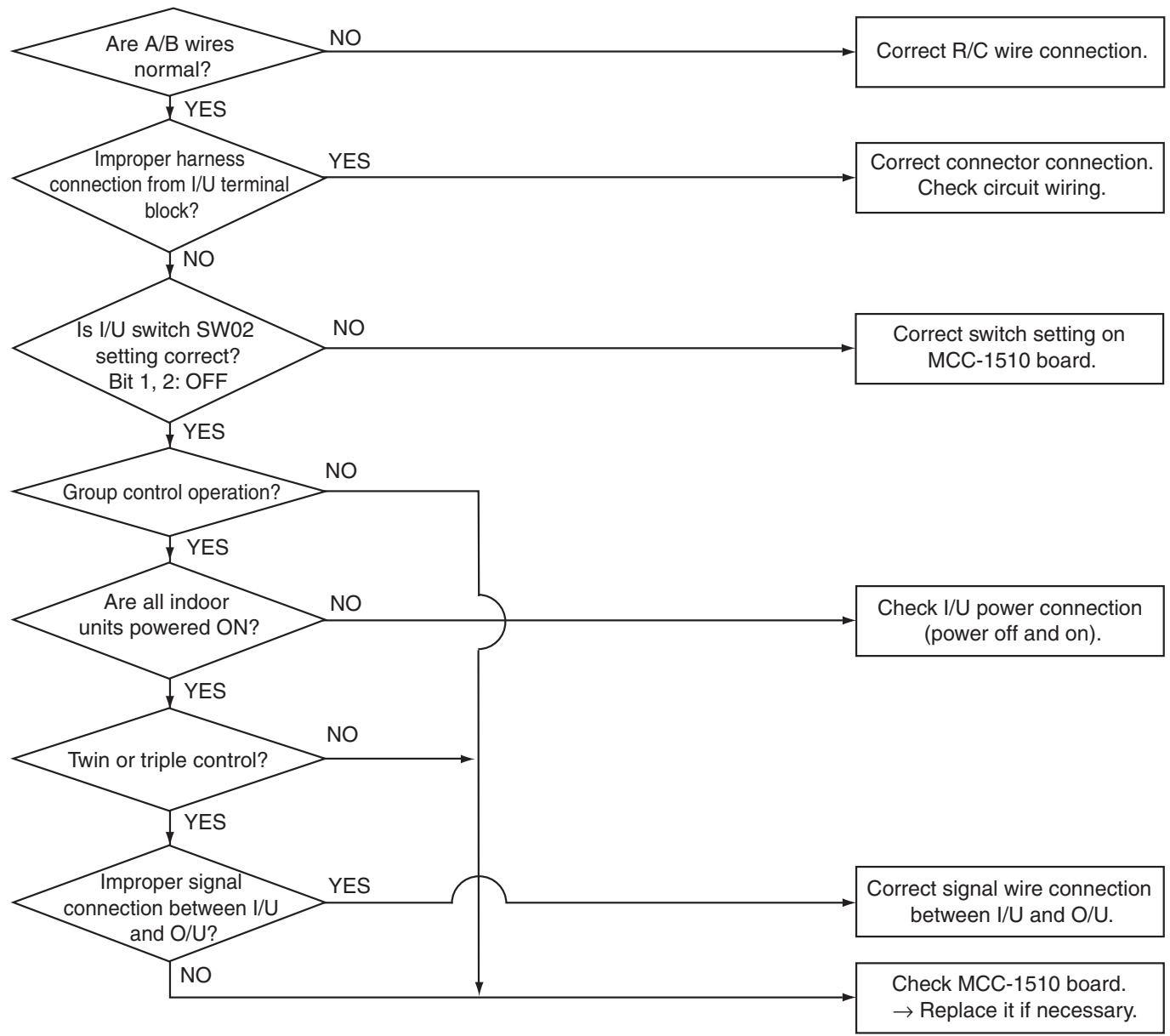
| [E18] (New code) | Communication error between header and follower I/U | ① Improper wire connection between I/U ② Improper wire connection between I/U and O/U ③ Failure of I/U board ④ Invalid I/U board switch setting |
Troubleshooting (Continued)
| Check code | Check code name | Possible causes |
| [F01] (New code) | I/U sensor TCJ error | I/U sensor TCJ error |
| Check code | Check code name | Possible causes |
| [F02] (New code) | I/U sensor TC error | Sensor TC open or short-circuit |

| Check code | Check code name | Possible causes |
| [F10] (New code) | I/U sensor TA error | Sensor TA open or short-circuit |
| Check code | Check code name | Possible causes |
| [F29] (New code) | Other indoor unit errors | Failure of I/U board |
This is an error of non-volatile EEPROM IC10 on the indoor unit board, which occurs during operation. Replace the service board.
- If EEPROM is not mounted at power on or if no data can be read/written from/in the EEPROM, auto address mode is repeated. At this time, the AI-NET central controller indicates code "97".
Troubleshooting (Continued)
| Check code | Check code name | Possible causes |
| [F31] (New code) | O/U EEPROM error | ①Failure of O/U power supply (voltage, noise, etc.) ②Failure of O/U CDB board. |
| Check code |
| [E08][L03][L07][L08] (New code/old code) |
E08: I/U number duplicated
L03: Multiple header I/U under group control
L07: One or more group address "individual" under group control
L08: I/U group address not set (99)
When any of these codes is detected at power on, the unit enters auto address setting mode automatically. (No code is indicated.)
However, if any of these codes is detected in the auto address setting mode, a check code is displayed in some cases.
| Check code | Check code name | Possible causes |
| [L09] (New code) | Indoor unit capacity not set | Indoor unit capacity not set |
| Check code | Check code name | Possible causes |
| [L20] (New code) | Duplication of central control address | Central control address is duplicated. |
| Check code | Check code name | Possible causes |
| [L30] (New code) | I/U external interlock | When an external alarm is input |
Troubleshooting (Continued)
| Check code | Check code name | Possible causes |
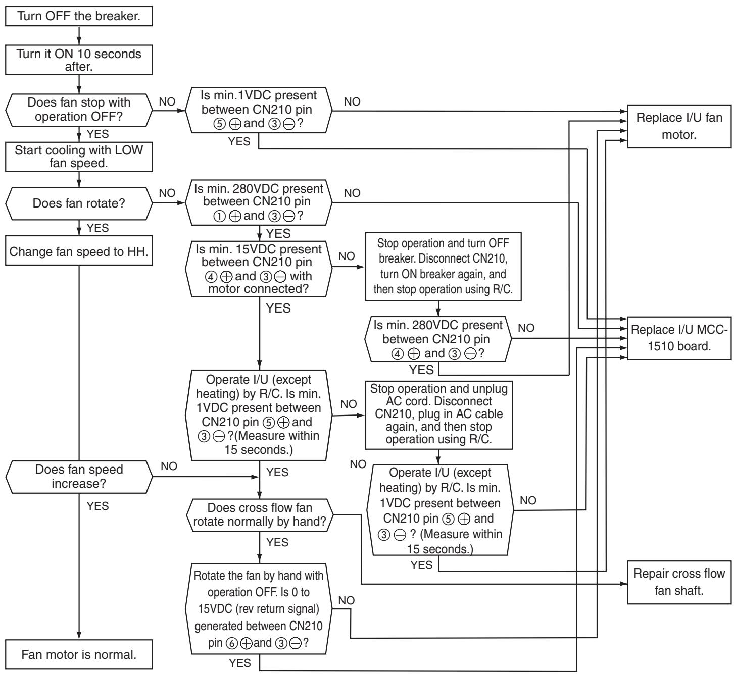
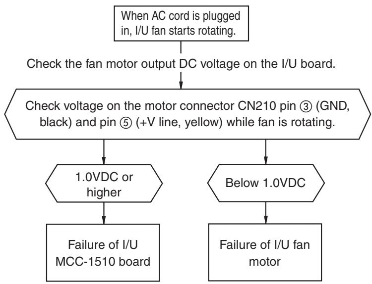
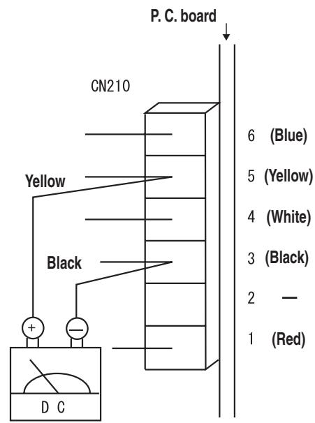
| [P12] (New code) | Malfunction of I/U fan motor | ① Failure of fan motor connector ② Failure of fan motor ③ Failure of I/U board ④ Failure of cross flow fan shaft |
| Check code | Check code name | Possible causes |
| [P12] (New code) | Malfunction of I/U fan motor | ① Failure of fan motor connector ② Failure of fan motor ③ Failure of I/U board ④ Failure of cross flow fan shaft |
Troubleshooting (Continued)
| Check code | Check code name | Possible causes |
| [P31] (New code) | Other I/U errors (Group follower I/U error) | When an error occurs with other units in the group |
When header unit detects E03, L03, L07 or L08 during group operation, "P31" is indicated on follower units in the group and their operation stops. No code or alarm log is displayed on the R/C.
| Check code | Check code name | Possible causes |
| [C05], [C06] (Central controller) | TCC-LINK central control communication error | TCC-LINK central control communication error |
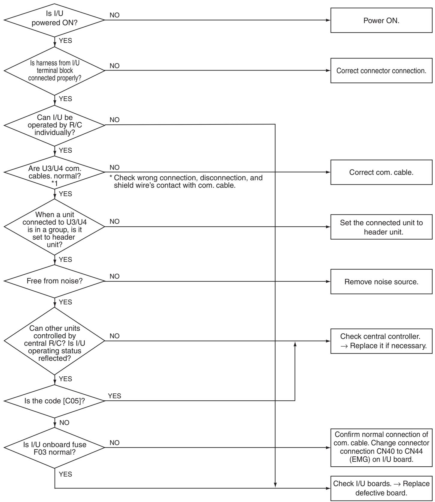
Troubleshooting (Continued)
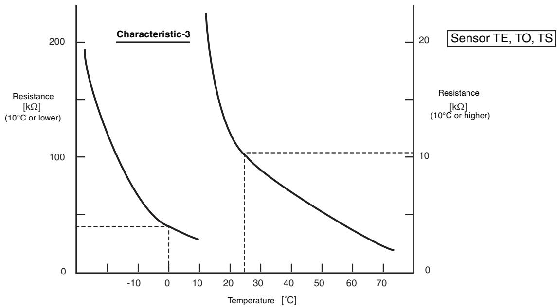
Relationship Between Temperature Sensor Resistance and Temperature
9. HOW TO REPLACE SERVICE BOARD OF INDOOR UNIT
Requirements When Replacing Service Board of Indoor Unit
The non-volatile EEPROM (IC10) on the board of indoor unit stores important data such as model-specific type and capacity code (written during factory shipping) as well as system/indoor unit/group addresses set automatically/manually (written during installation). Therefore, observe the following procedure when replacing indoor unit service boards. After installation of indoor unit, check whether the settings are correct by checking indoor unit number and group header/follower unit setting, and also check cycle through a trial operation.
[Replacement Procedures]
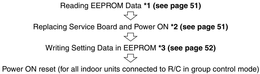
Case 1
When it is possible to power ON indoor unit before replacement and when wired R/C can read settings
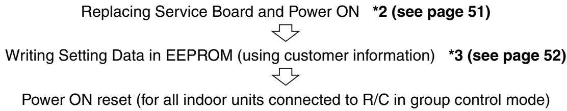
Case 2
When it is impossible to power ON indoor unit before replacement or when wired R/C is disabled due to failure of power supply circuit (board failure)
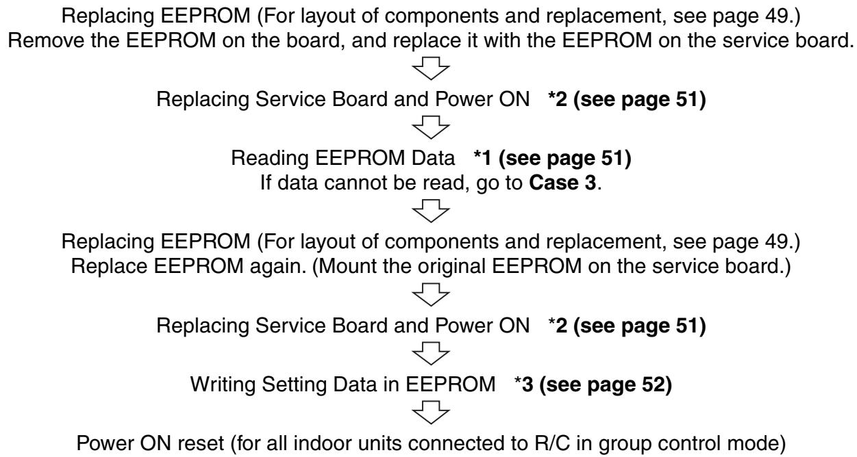
Case 3
When the EEPROM before replacement is defective, and the settings cannot be read
HOW TO REPLACE SERVICE BOARD OF INDOOR UNIT (Continued)
*1 Reading EEPROM Data
(Read EEPROM data that was updated at site in addition to factory setting.)
1) Press SET, CL, and on the R/C simultaneously for 4 seconds or more. (see page 52)
- In the group control mode, the header unit number is displayed first.
At this time, code (DN) 10 is displayed, and the fan of the selected indoor unit runs, its flap swings, and the OPERATION, TIMER, and PREPARING lamps blink.
2) Each pressing of UNIT indicates indoor unit number in the group sequentially. 2
Specify indoor unit number whose board is to be replaced.
3) Each pressing of TEMP. / buttons increments or decrements DN. 3
4) Change DN from I to I first. (Setting of filter sign ON time)
Write down the setting data displayed.
5) Change DN with TEMP. / buttons, and write down the setting data displayed.
6) Repeat step 5) in the same way, and write down the important setting data shown in the table (page 49).
DN = to Rb . DN does not always shift sequentially.
7) After writing down setting data, press to return the operation mode to normal OFF. 6
(It takes about one minute until R/C operation is enabled.)
Essential DN codes
| DN | Description |
| 11 | Indoor unit capacity |
| 12 | Refrigerant line address |
| 13 | Indoor unit address |
| 14 | Group address |
(1) Indoor unit capacity is necessary for fan speed setting.
(2) If refrigerant line address, indoor unit address or group address differs from that before replacement, the unit enters auto address setting mode, which requires manual re-setting for group operation including twin or triple operation.
*2 Replacing Service Board and Power ON
1) Replace the board with a service board.
Reflect the jumper wire (cut) setting and switch setting on the board in the service board. For switch setting and component layout, see page 53.
2) Power ON the indoor unit in either way of the following according to system configuration.
a) Single (individual) operation
Power ON the indoor unit with no operation.
i) Go to *3 when auto address setting mode ends (about 5 minutes).
(Refrigerant line address=1, indoor unit address=1, and group address=0 are set automatically.)
ii) Press SET, CL, and on the R/C simultaneously for 4 seconds or more (1) to cancel auto address setting mode, and then go to *3. (UNIT No. RL L is indicated.)
b) Group operation (including twin/triple/double twin)
Power ON the indoor unit whose service board is replaced in either way of the following.
i) Power ON the indoor unit only whose service board is replaced in the same way as a) i) and ii) above.
There must be remote controller connection. If not, operation *3 is disabled.
ii) Power ON multiple indoor units including the unit whose service board is replaced.
- Twin, triple, double twin: One system only
- Group control: All indoor units
Go to *3 when auto address setting mode ends (about 5 minutes).
- Header indoor unit may change depending on auto address setting. The refrigerant line address and indoor unit address of the indoor unit whose service board is replaced are automatically set to an address that is not used in other units. It is recommended that you take a memo beforehand that to which refrigerant system the indoor unit belongs and that the indoor unit is header or follower unit in the group.
*3 Writing Setting Data in EEPROM
(The data of the EEPROM on the service board is the factory setting data.)
1) Press SET, CL, and on the R/C simultaneously for 4 seconds or more. (see page 52)
- In the group control mode, the header unit number is displayed first.
(If auto address setting mode is canceled in 2-2) a) ii) above, UNIT No. RL L is indicated.)
At this time, code (DN) is displayed, and the fan of the selected indoor unit runs, its flap swings, and the OPERATION, TIMER, and PREPARING lamps blink.
2) Each pressing of UNIT indicates indoor unit number in the group sequentially. 2
Specify indoor unit number whose board is replaced.
(This operation is disabled if UNIT No. is RL L.)
3) Each pressing of TEMP. / buttons increments or decrements DN. 3
4) Set the indoor unit capacity first.
The factory setting data is written in the EEPROM.
i) Change DN to with TEMP. / buttons.
ii) Set the indoor unit capacity with TIME / buttons. (for example, "0012" for 80 class) ... See the table (page 53).
iii) Press SET Indication on the LCD shows normal operation.
iv) Press to return the operation mode to normal OFF. (It takes about one minute until R/C operation is enabled.)
5) Write the data set after installation (such as address) in the EEPROM. Repeat steps 1) and 2) above.
6) Specify DN I with TEMP. / buttons. (Setting of filter sign ON time)
7) Check the displayed data comparing the content written down in *1 (page 49).
i) If the data is incorrect, change it with TIME / buttons to the data of the memo, and then press Indication on the LCD shows normal operation.
ii) No operation is required for the same data.
8) Change DN with TEMP. / buttons.
In the same way as above, check the displayed data comparing the content of the memo.
If the data is incorrect, change it to the data of the memo.
9) Repeat steps 7) and 8) above.
10) When the setting is completed, press to return the operation mode to normal OFF. 6
(It takes about one minute until R/C operation is enabled.)
- DN = ∅ to R. DN does not always shift sequentially. Even if data is updated and SET button is pressed by mistake, the previous data can be restored with CL button unless DN is changed.
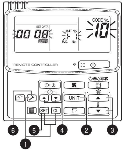
RBC-AMT21E
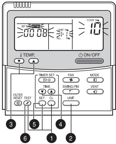
RBC-AMT31E
HOW TO REPLACE SERVICE BOARD OF INDOOR UNIT (Continued)
Example of Setting Contents to be Written Down (Code Table)
| DN | Item | Memo | Factory setting |
| 01 | Filter sign ON time | 0001: 150 hours | |
| 02 | Filter contamination level | 0000: Average | |
| 03 | Central control address | 0099: Not determined | |
| 06 | HEAT intake temp. shift | 0002: +2°C | |
| 0C | PREPARING indication selection | 0000: Normal | |
| 0F | COOL only | 0000: Heat pump type air conditioner | |
| 10 | Type | Must be set to 0008 | 0008: Wall type |
| 11 | Indoor unit capacity | Depends on capacity type | |
| 12 | Refrigerant line address | 0099: Not determined | |
| 13 | Indoor unit address | 0099: Not determined | |
| 14 | Group address | 0099: Not determined | |
| 1E | Temp. range at COOL/HEAT auto switching control | 0003: 3°C (Ts±1.5) | |
| 28 | Auto restart after power failure | 0000: Not provided | |
| 2A | Option/alarm input (CN80) selection | 0002: External alarm input | |
| 2b | Thermo output (T10-③) selection | 0000: Thermo output ON | |
| 2E | HA terminal (T10-①) selection | 0000: Operation input | |
| 31 | Ventilation fan (single operation) | 0000: Disabled | |
| 32 | Sensor selection | 0000: Unit sensor | |
| 60 | Timer setting (wired R/C) | 0000: Available | |
| 69 | Flap setting for cooling | 0000: Normal | |
| 8b | Correction of feeling of strong heating | 0000: Not provided |
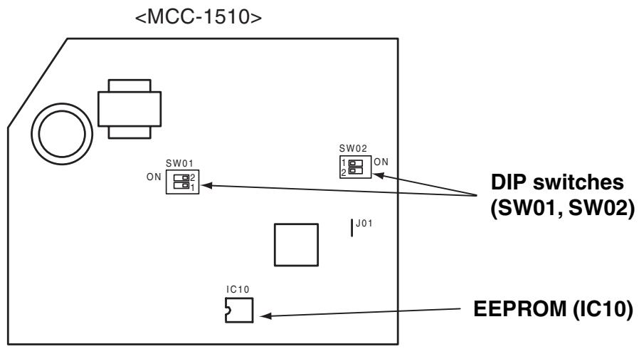
Onboard Component Layout
Indoor unit capacity Code "11"
| Setting data | Model |
| 0000* | Invalid |
| 0006 | 40 type |
| 0007 | 45 |
| 0008 | 50 |
| 0009 | 56 |
| 0010 | 63 |
| 0011 | 71 |
| 0012 | 80 |
- Default value of EEPROM on the service board
Mount EEPROM aligning its notch with the notch of IC socket.
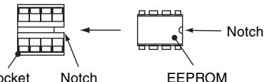
DIP switch setting
| Setting | AIK-AP**1H | Factory setting | ||
| SW01 | Bit 1 | Terminating resistor (for central control) | *1 | OFF (no resistor) |
| Bit 2 | Selection of R/C A or B | *1 | OFF (A is selected) | |
| SW02 | Bit 1 | Selection of custom or multiple | OFF | OFF (custom models) |
| Bit 2 | Not used | OFF | OFF | |
*1: Set to the state before replacement
10. ON-SITE SETTING AND OTHERS
1. Indoor Unit
1.1 Trial Operation Setting by Remote Controller
The lamps on the unit blink during trial operation.
< Wired remote controller>
Press TEST on the R/C for 4 seconds. When "TRIAL OPERATION" appears on the LCD, press ON/OFF.
- "TRIAL OPERATION" appears on the LCD during trial operation.
- Trial operation disables temperature control, but allows fan speed control.
- An instruction of fixed frequency is issued for cooling and heating of trial operation.
- Alarm detection is performed as usual.
The trial operation mode must be used for its original purpose only, because it stresses the air conditioner.
Choose COOL or HEAT mode only for trial operation.
- (Note) Outdoor unit does not run about 3 minutes after power on or operation stop.
3 Repress ⑤ after trial operation and confirm that “TRIAL OPERATION” disappears from the LCD.
Wired remote controller has 60-minute timer reset function to prevent continuous trial operation.
(1) Power ON the unit.
No operation mode is available for about 5 minutes from the first power on after installation or for one minute from the second (or later) power on. Perform trial operation after this time passes.
② Press [ON/OFF] on the R/C, chose COOL or HEAT with [MODE] button, and then choose HH with [FAN] button.
(3) For COOL trial operation, set 18^ C with [TEMP.] button.
For HEAT trial operation, set 30^ with [TEMP.] button.
④ For COOL trial operation, set 19^ with [TEMP.] button upon hearing a reception sound "pi".
For HEAT trial operation, set 29^ with [TEMP.] button upon hearing a reception sound "pi".
⑤ For COOL trial operation, set 18^ with [TEMP.] button upon hearing a reception sound "pi".
For HEAT trial operation, set 30^ with [TEMP.] button upon hearing a reception sound "pi".
⑥ Repeat steps ④ ⑤ ④ ⑤.
About 10 seconds after, the green OPERATION lamp, green TIMER lamp, and yellow PREPARING lamp blink and operation starts. If any lamp does not blink, perform operation again from step 2.
(7) When the trial operation ends, press [ON/OFF] to stop operation.
COOL trial operation: Press [ON/OFF] 18^ 19^ 18^ 19^ 18^ 19^ 18^ (trial operation) press [ON/OFF]
HEAT trial operation: Press [ON/OFF] 30^ 29^ 30^ 29^ 30^ 29^ 30^ (trial operation) press [ON/OFF]
- Checking wiring and piping of indoor/outdoor units
- Open the front panel of the indoor unit.
- Press [TEMPORARY] button for 10 seconds. The unit enters forcible cooling mode with a sound "pi". COOL operation starts forcibly about 3 minutes later. Check whether cool air is discharged. If COOL operation does not start, recheck the wiring.
- Repress [TEMPORARY] for about one second to stop trial operation. The vertical airflow flap closes and the operation stops.
- Checking signal transmission from R/C
- Press [ON/OFF] on the R/C to check for normal operation using R/C.
- To enter AUTO mode, press [TEMPORARY] once for about one second.
For forcible cooling, press [TEMPORARY] for 10 seconds or more.
- COOL operation specified by R/C may not start depending on temperature conditions.
Use forcible cooling operation to check wiring and piping of indoor/outdoor units.
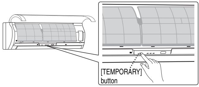
ON-SITE SETTING AND OTHERS (Continued)
1.2 Forcible Defrost Setting by Remote Controller (wired R/C only)
Preliminary operation
Press TEST, SET, and CL at the same time for 4 seconds or more in the OFF mode. In the group control mode, the header unit number is displayed first.
Each pressing of UNIT indicates indoor unit number in the group sequentially. Choose the main indoor unit (connected to the outdoor unit) for which forcible defrosting is to be performed. The fan and flap of the selected indoor unit start working.
3 Specify DN "8C" with TEMP. 4 buttons.
4 Set data 0001 with buttons. (Factory setting: 0000)
Press SET Indication on the LCD shows normal operation.
6 Press TEST to return the operation mode to normal OFF.
Execution procedure
- Press ON/OFF on the R/C.
- Choose HEAT operation mode.
- After a while, a forcible defrosting signal is transmitted to the outdoor unit. Upon receiving the signal, the outdoor unit starts defrosting. It takes up to 12 minutes.
- On completion of defrosting, the indoor unit restart HEAT operation.
To reexecute defrosting, repeat steps from step 1 above. Once forcible defrosting is performed, the above setting for forcible defrosting is reset.
1.3 Indication of Onboard LEDs
1. D02 (red)
- Lights up by the control of main microcomputer when the indoor unit is powered on.
- Blinks at intervals of one second (0.5-second on and off) when EEPROM is not mounted or write error occurs.
- Blinks at intervals of 10 seconds (5-second on and off) in the DISP mode. (CN72 short-circuited at power on)
- Blinks at intervals of 2 seconds (1-second on and off): Applicable unit in the EEPROM setting (address, function selection, etc.) mode
2. D203 (red)
- Lights up by hardware control when power is supplied to remote controller.
1.4 JRA Capacity Measurement Mode (wired R/C only)
Preliminary operation
Press TEST, SET, and CL at the same time for 4 seconds or more in the OFF mode. In the group control mode, the header unit number is displayed first.
Each pressing of UNIT indicates indoor unit number in the group sequentially. Choose the main indoor unit (connected to the outdoor unit) for which this control is to be performed. The fan and flap of the selected indoor unit start working.
3 Specify DN "91" with TEMP. 7 buttons.
4 Set the following data with TIME buttons. (Factory setting: 0000)
| Data | |
| Rating | 0001 |
| Middle | 0002 |
Press SET Indication on the LCD shows normal operation.
Press to return the operation mode to normal OFF.
- Use this mode to measure JRA capacity.
Use this mode under the conditions of JIS B8615-1. - Perform the settings in the table by remote controller.
| Operation | Fan speed | Setting temp. | Flap position | |
| Cooling rating | Cooling | Quick high | 18°C | Horizontal angle |
| Heating rating | Heating | Quick high | 29°C | Horizontal angle |
| Cooling middle | Auto Cooling | Auto | 23°C | Horizontal angle |
| Heating middle | Auto Cooling | Auto | 24°C | Horizontal angle |
Execution procedure
- Press ON/OFF on the R/C.
To reexecute JRA capacity measurement, repeat steps from step 1 above. Once this measurement is completed, the above setting is reset.
1.5 Function Select Setting (wired R/C only)
Perform the following steps in the operation OFF mode.
Press TEST, SET, and CL at the same time for 4 seconds or more in the OFF mode.
In the group control mode, the header unit number is displayed first.

Each pressing of UNIT indicates indoor unit number in the group sequentially.
Choose the main indoor unit (connected to the outdoor unit) this function is to be performed.
The fan and flap of the selected indoor unit start working.

3 Specify DN with TEMP. 4 buttons.

4 Set the setting data with TIME buttons.

Press SET Indication on the LCD shows normal operation.
- To change the selected indoor unit, go to 2.
To change the item to be set, go to 3

6 Press TEST to return the operation mode to normal OFF.
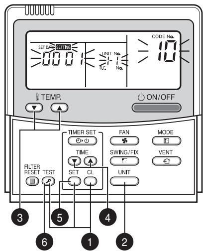
Operation procedure
1→2→3→4→5→6END
ON-SITE SETTING AND OTHERS (Continued)
Function Select Code (DN) Table
| DN | Item | Description | Factory setting | |
| 01 | Filter sign ON time | 0000: None | 0001: 150H | 0001: 150H |
| 0002: 2500H | 0003: 5000H | |||
| 0004: 10000H | 0005: Clogging sensor used | |||
| 02 | Filter contamination level | 0000: Average | 0001: Heavy (half of standard time) | 0000: Average |
| 03 | Central control address | 0001: No. 1 - 0099: Not determined | 0064: No. 64 | 0099: Not determined |
| 06 | HEAT intake temp. shift | 0000: No shift | 0001: +1 °C | 0002: +2 °C |
| 0002: +2 °C - | 0010: +10 °C (Up to +6 recommended) | |||
| OC | PREPARING indication selection | 0000: PREPARING indicated | 0001: No indication | 0000: PREPARING indicated |
| OF | COOL only | 0000: Heat pump | 0001: COOL only (No “AUTO”, “HEAT” indication) | 0000: Heat pump |
| 10 | Type | 0000: (Ceiling panel 1) | 0001 (ceiling panel 4) - 0037 | 0008: Wall type |
| 11 | Indoor unit capacity | 0000: Not determined | 0001 - 0034 | Depends on capacity type |
| 12 | Refrigerant line address | 0001: No. 1 - | 0030: No. 30 | 0099: Not determined |
| 13 | Indoor unit address | 0001: No. 1 - | 0064: No. 64 | 0099: Not determined |
| 14 | Group address | 0000: Individual | 0001: Group header | 0099: Not determined |
| 0002: Group follower | ||||
| 1E | Temp. range at COOL/HEAT auto switching control | 0000: 0deg - (Switching at set temperature ±(data)/2) | 0010: 10deg (Switching at set temperature ±(data)/2) | 0033: 3deg (Ts ± 1.5) |
| 28 | Auto restart after power failure | 0000: Not provided | 0001: Provided | 0000: Not provided |
| 2A | Option/alarm input (CN80) selection | 0000: Filter input | 0001: Alarm input | 0002: External alarm input |
| 0002: External alarm input | ||||
| 2b | Thermo output (T10-3) selection | 0000: I/U thermo sensor ON | 0001: O/U compressor ON output | 0000: I/U thermo sensor ON |
| 2E | HA terminal (T10-1) selection | 0000: Normal (JEMA) | 0001: Card input | 0000: Normal (HA terminal) |
| 0002: Fire alarm input | ||||
| 31 | Ventilation fan (single operation) | 0000: Disabled | 0001: Enabled | 0000: Disabled |
| 32 | Sensor selection | 0000: Unit sensor TA | 0001: R/C sensor | 0000: Unit sensor |
| 60 | Timer setting (wired R/C) | 0000: Available | 0001: Unavailable | 0000: Available |
| 69 | Flap setting for cooling | 0000: Normal | 0001: Down allowed | 0000: Normal |
| 8b | Correction of feeling of strong heating | 0000: Not provided | 0001: Provided | 0000: Not provided |
1.6 Wiring and Setting for Remote Controller
Double R/C control (when controlling by two remote controller switches)
This control is provided to control one or more indoor units by two remote controllers. Up to 2 remote controllers can be installed.
No setting is required when using in combination with a wireless remote controller (RBC-ATX12E).
- Controlling one indoor unit by 2 remote controllers
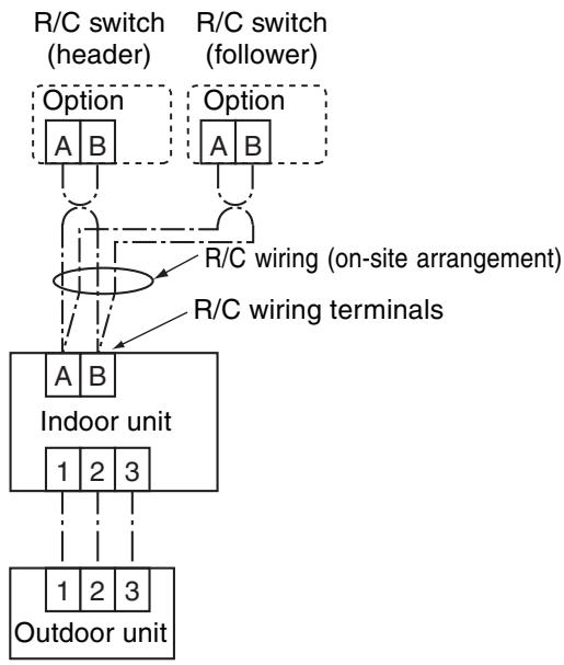
- Controlling 3 indoor units by 2 remote controllers
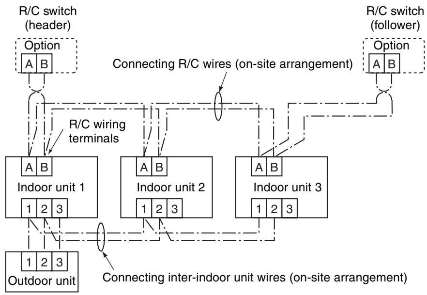
Setting
This control is provided to control one or more indoor units by two remote controllers.
Up to 2 remote controllers can be installed.
< Wired remote controller>
Setting to use a wired remote controller as follower R/C:
Change the setting of DIP switch on the back of R/C switch to “R/C follower” as shown in the figure.
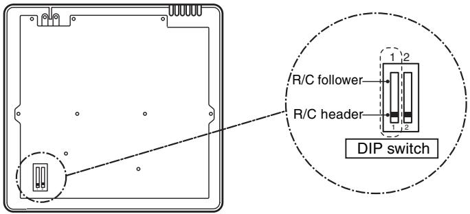
Remote controller (back, inside)
ON-SITE SETTING AND OTHERS (Continued)
1.7 Monitoring Function of Remote Controller Switch
■ Calling indication of sensor temperature
Calls the service monitor mode from the remote controller to monitor sensor temperatures of the remote controller, indoor units, and outdoor unit.
Press TEST and CL on the R/C simultaneously for 4 seconds or more to call the service monitor mode.
"Service monitor" lights up and the header indoor unit number is displayed first, and then temperature of code "00" is displayed.

2 Choose a sensor number (code) you want to monitor with TEMP. ② ④ buttons.
The following table lists sensor numbers.
| Indoor unit data | Code | Data |
| 00 | Room temp. under control *1 | |
| 01 | Room temp. (R/C) | |
| 02 | Indoor unit intake temp. | |
| 03 | Indoor unit coil temp. TCJ | |
| 04 | Indoor unit coil temp. TC | |
| 05 | Indoor unit coil temp. TC1 |
| Outdoor unit data | Code | Data |
| 60 | Heat exchange temp. TE | |
| 61 | Outside air temp. TO | |
| 62 | Discharge temp. TD | |
| 63 | Intake temp. TS | |
| 64 | - | |
| 65 | Heatsink temp. THS |
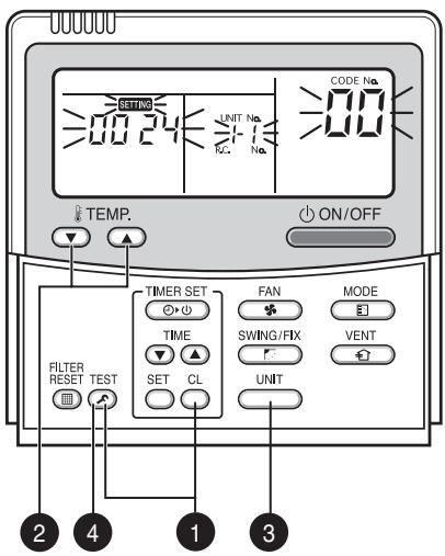
Returns to normal indication. Operation procedure 1 2 3 4
*1 Header indoor unit only under group control

3 Choose an indoor unit you want to monitor with button to monitor sensor temperatures of indoor units and outdoor unit in the same control group.

Press TEST to return to the normal indication.
■Calling error log
Calls past errors.
Press TEST and CL on the R/C simultaneously for 4 seconds or more to call the service check mode.
"Service check" lights up and code B is displayed first to display the latest error.
The faulty indoor unit number and error content are displayed.

To monitor other errors, change error log number (code) with TEMP. buttons.
Code ^ (latest) Code ^ (oldest)
Note) Up to 4 errors are memorized in the error log.

Press TEST to return to the normal indication.
Do not press as this button clears entire error log of indoor unit.
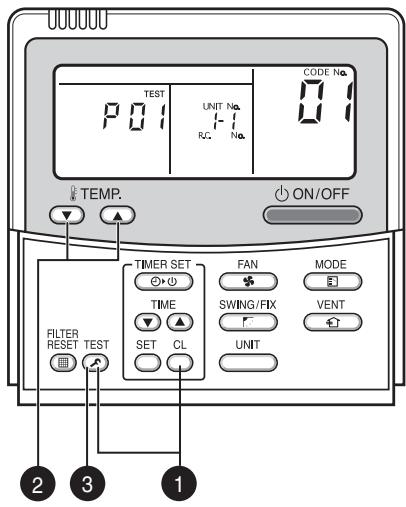
Returns to normal indication.
Operation procedure

ON-SITE SETTING AND OTHERS (Continued)
Group control allows operation control of up to 8 indoor units using one remote controller. It includes twin, triple, and double twin controls with one outdoor unit.
The indoor unit connected to outdoor unit controls room temperature according to the R/C setting.
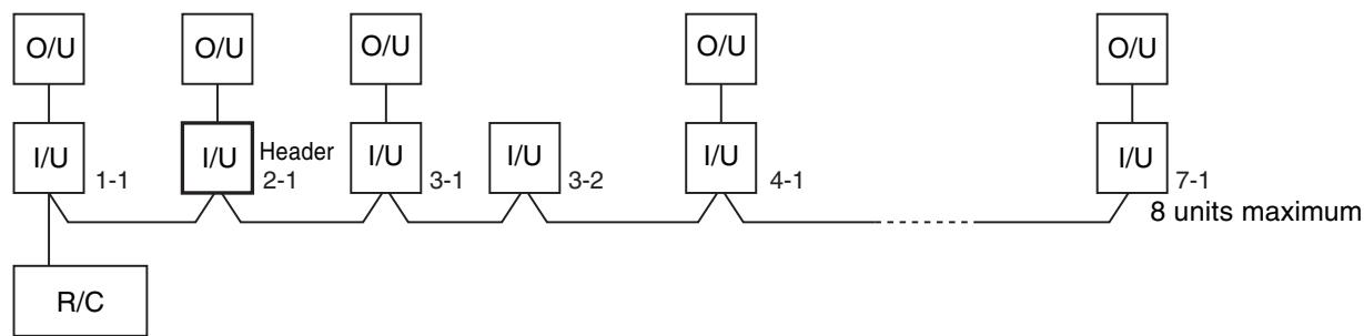
(1) Scope of R/C indication
The indoor unit setting range (operation mode/fan speed/temperature) set in the header unit is reflected in the remote controller.
① Do not set a concealed duct high static pressure type (AID-P***1H) for header unit.
- If the type is set as header unit, settings are as follows.
Operation mode: [Auto cooling/heating], [HEAT], [COOL] or [FAN] without [DRY]
Fan speed : [HH]
- In the DRY operation mode, FAN mode is not available for duct models.
(2) Do not set a "COOL only" model for header unit.
- [Auto cooling/heating] and [HEAT] operation modes are not available.
(2) HA
Both indoor and outdoor units are compatible with the remote control HA.
Operation ON/OFF control for entire group is available.
(1) Multiple HA inputs in one group are not allowed.
(3) Address setting
If there is no serial data communication between indoor and outdoor units at power on, the indoor unit is regarded as twin follower unit. (Each time of power on)
... Recognition of twin header (main)/follower (sub) is carried out at each power on, and the result is not stored in the non-volatile memory.
When performing auto address setting, power on the indoor units in a control group within 3 minutes.
... If powered on after 3 minutes when auto address judgment is completed, the unit is rebooted and reenters auto address setting mode.
① Connect 3 wires between indoor and outdoor units properly.
② Check refrigerant line address, indoor unit address, and group address of each unit.
Regarding twin, triple, and double twin, in particular, check for one refrigerant line address for all units.
(3) An indoor unit number (refrigerant line address/group address), once it is set, is retained in principle unless it is not used for any other unit.
Indoor Unit Power ON Sequence
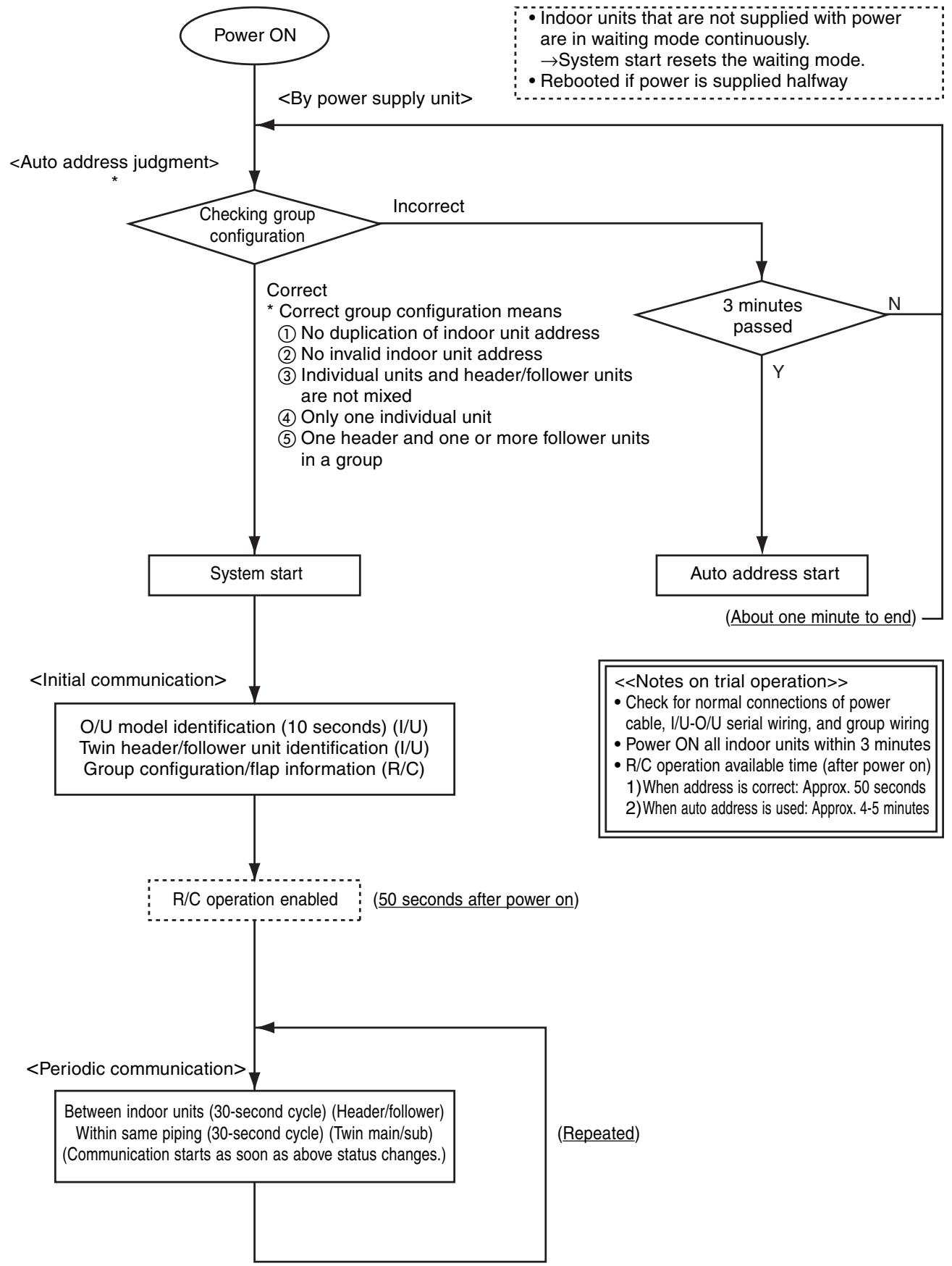
- The indoor unit powered on after auto address judgment under group control is rebooted (system reset), unless it does not receive data from the header unit or periodic communication within same piping within 120 seconds after power on.
→The sequence restarts from auto address judgment (checking group configuration). - If the previous address fixed and the header unit is powered on and is rebooted, the refrigerant line address of indoor units remains unchanged, but the header unit address may change.
ON-SITE SETTING AND OTHERS (Continued)
3. Connections for Central Control
3.1 Connections for TCC-LINK Central Control
3.1.1 Functions
Connect an indoor unit to the TCC-LINK central controller.
3.1.2 Connection Diagram
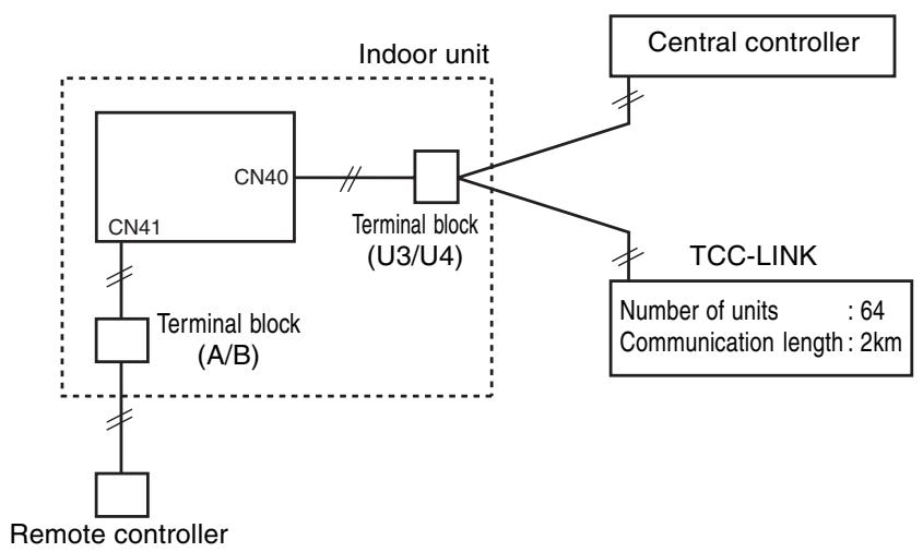
3.1.3 TCC-LINK Connections
How to make connections
The terminal block for TCC-LINK central control is located at the lower right of the indoor unit.
For details, see the installation manual of applicable central control remote control system.
When using the terminal block, detach the front panel following the description on how to replace main components in this manual.
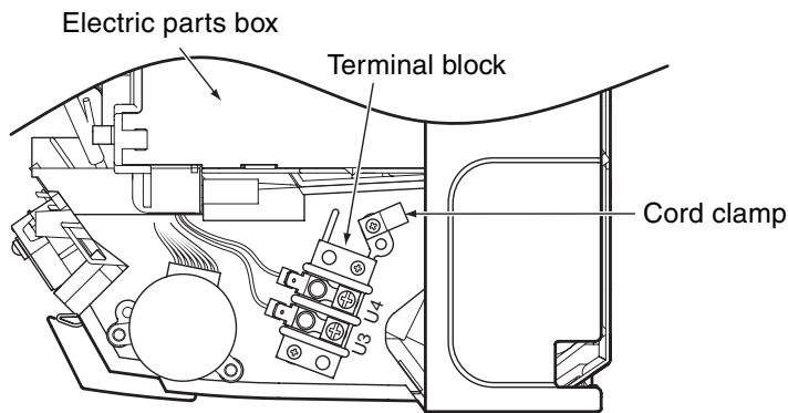
Terminal block for central control wiring (lower right part without front panel)
3.1.4 Wiring Specifications
| Number of wires | Size | Specification |
| 2 | Up to 1000m: 1.25mm2 stranded wires | MVVS |
| Up to 2000m: 2.0mm2 stranded wires |
- A 2-wire non-polarity cable is used.
- The cable length depends on each central control system.
When used in a system including multiple air conditioners, the length includes the length of all wires between indoor and outdoor units on the side of multiple air conditioners.
- Use 2-wire shield cable (MVVS) to protect from noise.
- Joint shield wire between indoor units by closed-end terminating, and leave its end open with insulation processing.
Make one-point grounding at the indoor unit side. Set the terminating resistors.
(Central control for custom indoor units only)
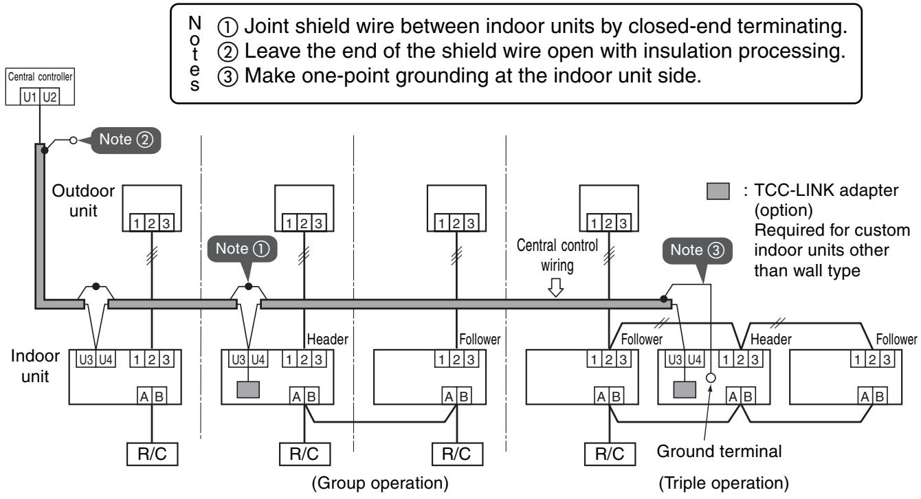
ON-SITE SETTING AND OTHERS (Continued)
3.1.5 Setting Onboard Switches
Setting of terminating resistors is necessary for central control of custom indoor units only.
- Use SW01 to set terminating resistors.
- Set terminating resistors for the indoor unit only with the smallest refrigerant line address.
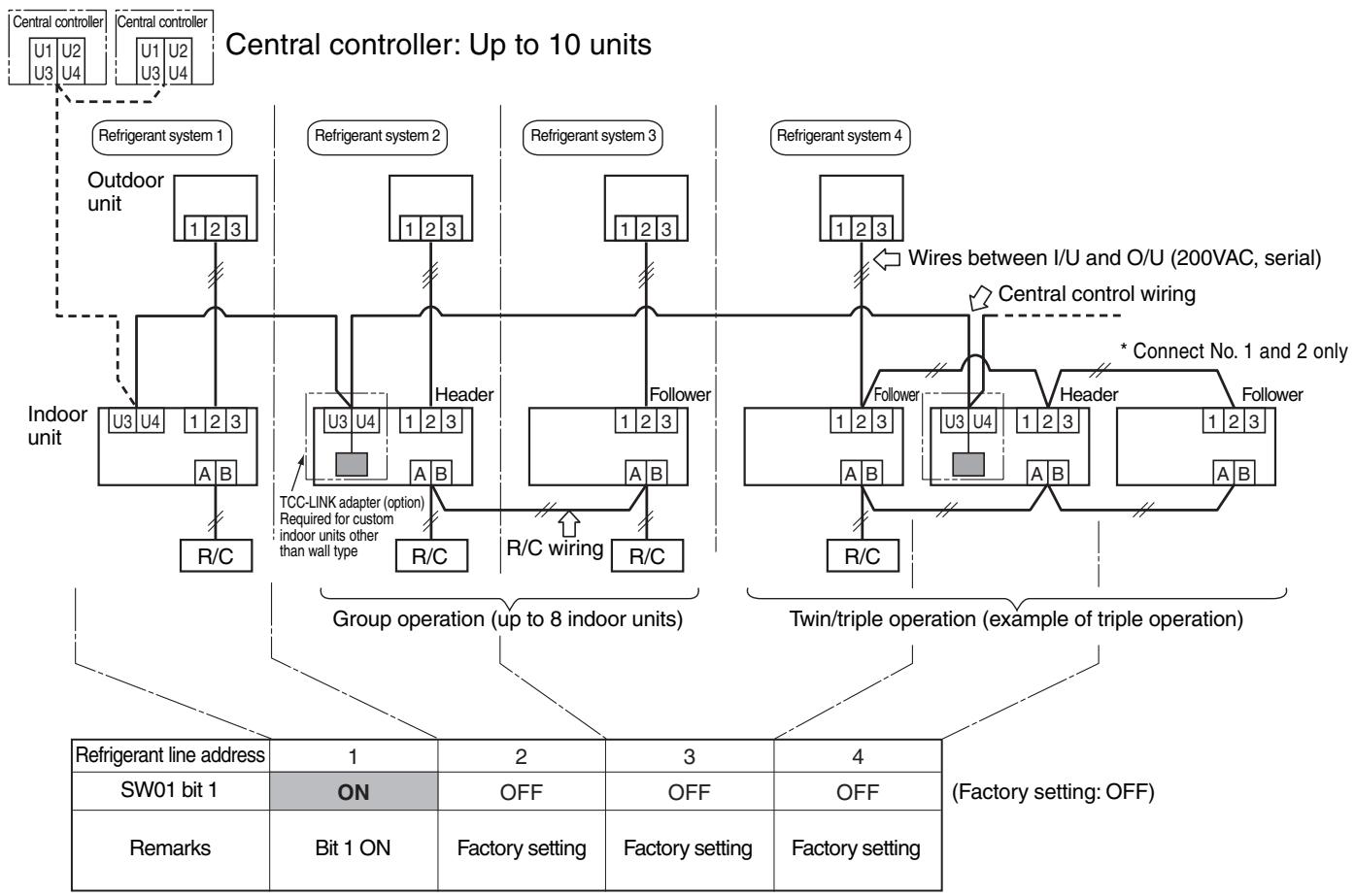
3.1.6 Onboard Switch Setting Procedure
- Detach the front panel.
- Remove the drain guide, ground line, sensor TCJ, sensor TC, and motor leads.
- Remove the screws to detach the electric parts box.
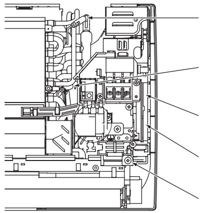
Sensor TCJ insertion position
(Insert the sensor drawn from above electric parts.)
Sensor TC insertion position
(Insert the sensor drawn from under electric parts.)
Fan motor connector insertion position
Louver motor connector insertion position
Electric parts box screw
- Detach the electric parts cover, and set SW01 bit 1 to ON. Do not touch bit 2 as it is for other setting.
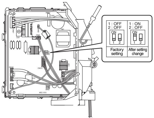
- Install the removed parts by reversing steps 1 to 4. (Insert the sensors and motor leads firmly into their correct positions.)
ON-SITE SETTING AND OTHERS
3.1.7 Setting Addresses
Overview
To connect custom air conditioners to the TCC-LINK central control system for central control/monitoring, addresses of connected indoor units must be set in the following procedure.
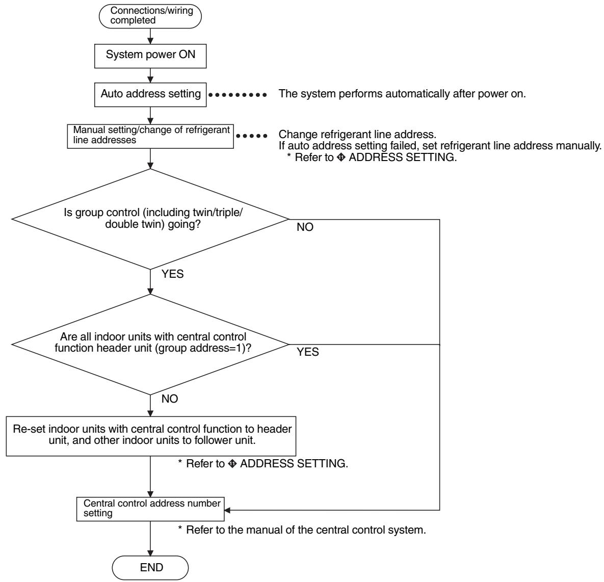
(1) Manual setting/change of indoor unit refrigerant line addresses
[In the case of 29 refrigerant systems or less (when multiple air conditioners are included, their number of refrigerant systems is also included)]
Refrigerant address "1" is assigned to all indoor units except for group control by the auto address setting after system power on. Therefore, change refrigerant line address of each refrigerant system using the wired remote controller.

- For changing/setting refrigerant line addresses by wired remote controller, refer to ◆ ADDRESS SETTING.
- Refrigerant line address must be unique for each refrigerant system. To perform central control in combination of multiple and custom air conditioners, set refrigerant line addresses different from those of multiple air conditioners.
(2) Manual setting/change of indoor unit refrigerant line addresses
[In the case of 30 refrigerant systems or more (when multiple air conditioners are included, their number of refrigerant systems is also included)]
Regarding refrigerant systems up to No. 29, manual setting/change is the same as that on the previous page.
- Refrigerant address "1" is assigned to all indoor units except for group control by the auto address setting after system power on. Therefore, change refrigerant line address of each refrigerant system using the wired remote controller.
- Also change indoor unit addresses so as to avoid duplication of indoor unit numbers.
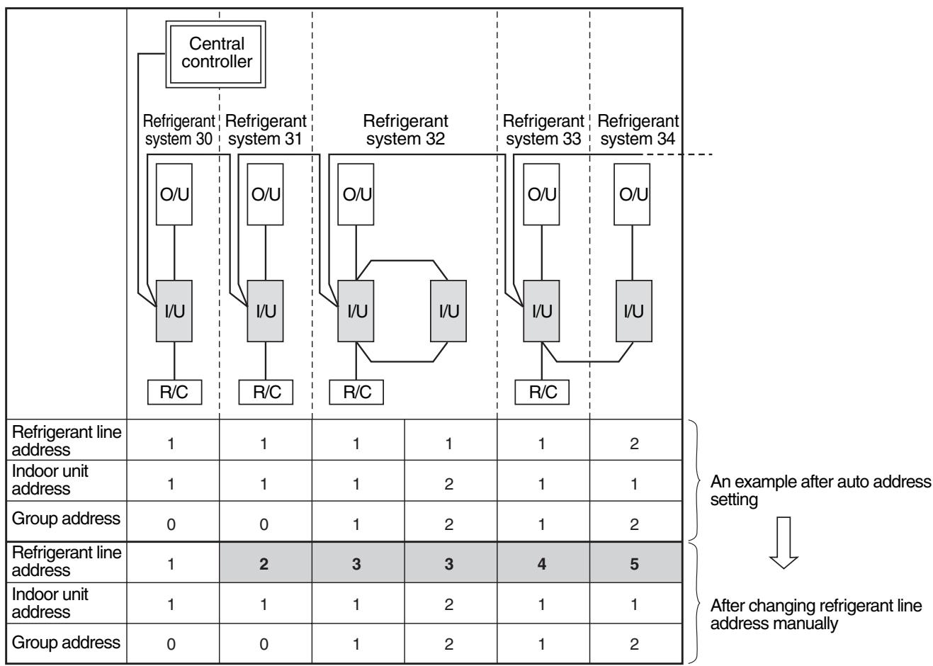
For changing/setting refrigerant line addresses by wired remote controller, refer to ◆ ADDRESS SETTING.
Change refrigerant line address of all indoor units connected directly to the central controller to "30".
These indoor units are under twin or triple control, also change the refrigerant line address of follower indoor units to "30".
- Change indoor unit addresses so that they are not duplicated.
3.1.8 Central Control Address Number Setting
To connect an indoor unit to the central control remote controller, an address number for central control must be set.
- An address number for central control is indicated as the refrigerant line number of the remote controller.
1. Setting by Remote Controller on Indoor Unit Side
Press TEST and VENT on the R/C simultaneously for 4 seconds or more.
When group control is going, UNIT No. R_L^L is displayed first, and all indoor units in the group are selected. At this time, the fans of all the selected indoor units start running. (Fig. 1) Maintain this state without pressing .
For individual remote controllers without group control, a refrigerant line address and an indoor unit address are indicated.

2 Specify code 03 with TEMP.

3 Choose setting data with TME 1 Table 1 shows setting data.

4 Press SE Indication on the LCD shows normal operation.
- To change an item for setting, return to 2.

Press to return to the normal indication.
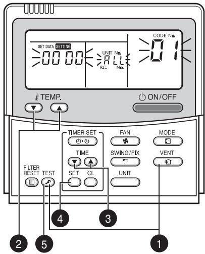
(Fig. 1)
Table 1
| Setting data | Address No. for central control |
| 0001 | 1 |
| 0002 | 2 |
| 0003 | 3 |
| ··· | ··· |
| 0064 | 64 |
| 0099 | Not set (factory setting) |
11. ADDRESS SETTING
1. Address Setting
Address Setting Procedure
When twin or triple operation is selected with one indoor unit and one outdoor unit or when one outdoor is connected to each indoor unit even with multiple refrigerant systems in group operation, auto address setting is completed during the power on process of outdoor unit.
Remote controller operation is disabled during the auto address setting process (4 to 5 minutes).
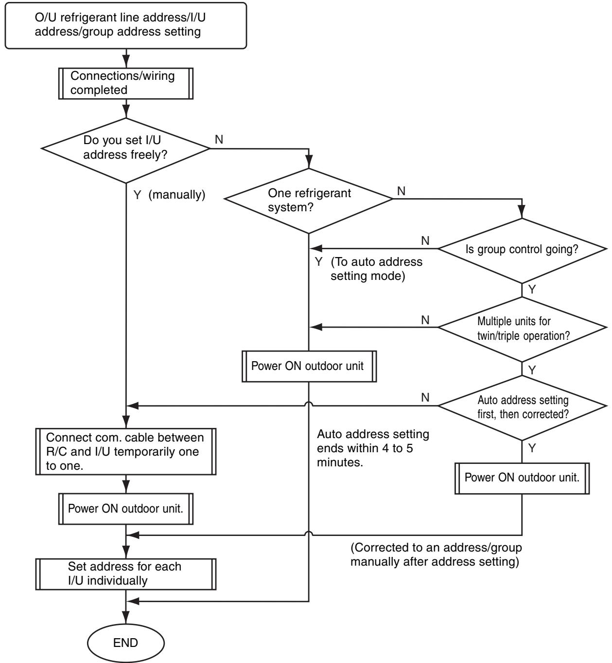
- Unless the following addresses are stored in the EEPROM (IC10) on the indoor unit board, trial operation is disabled. (Undefined data is stored at factory shipping.)
| Code | Factory setting data | Setting data range | |
| Refrigerant line address | 12 | 0099 | 0001 (unit No. 1) to 0030 (unit No. 30) |
| Indoor unit address | 13 | 0099 | 0001 (unit No. 1) to 0064 (unit No. 64) Maximum I/U address in the same refrigerant system (double twin=4) |
| Group address | 14 | 0099 | 0000 : Individual (indoor units without group control) 0001 : Header (one indoor unit in the group) 0002 : Follower (indoor units in the group except header unit) |
2. Address Setting and Group/Twin/Triple Control
Indoor unit No.
: N-n=O/U refrigerant line address N (30 max.) -I/U address n (64 max.)
Group address
: 0=Individual (without group control)
1=Header unit under group control
2=Follower units under group control
Header indoor unit (= 1)
: A representative unit of multiple indoor units in group operation, which performs communication between R/C and follower I/U. (* It does not mean an indoor unit that communicates with O/U.)
Operation mode and setting temperature range (except flap air flow control) of header unit are reflected on the LCD of remote controller.
Follower indoor unit (= 2)
: Indoor units except header unit in group operation.
It does not control communication with remote controller in principle (except response to alarm/service data request).
Main unit (Representative)
: In a minimal configuration of refrigerant cycle such as twin, triple or double twin, an indoor unit which communicates with O/U among those with same refrigerant line address.
(Twin header)
Communicates with sub indoor units and with O/U (instructions to compressor) on behalf of cycle control.
Sub indoor unit (Sub unit)
: Indoor units except the main indoor unit in a twin, triple or double twin system.
(Twin follower)
Communicates with the main indoor unit with the same refrigerant line address, and provides control in synchronization with the main indoor unit. It does not communicate with O/U (no detection of serial signal alarm).
[1] System Configuration
![TOSHIBA RAV-SM801KRT-E - [1] System Configuration - 1](/content/2025/01/121651/images/f944150b9b4d3555ce2fedc3f6c15d9fa768addcd55af846e9780f77162a1a5c.jpg)
a) Single
![TOSHIBA RAV-SM801KRT-E - [1] System Configuration - 2](/content/2025/01/121651/images/ab2142b37f77221fa88e4e78a184e62b766746b036308e87f90e57882fb11254.jpg)
b) Twin/triple/double twin
![TOSHIBA RAV-SM801KRT-E - [1] System Configuration - 3](/content/2025/01/121651/images/1595fc194da74d8e82eb97f03018a88f3672fda1e69981f6f03522b0f3f118db.jpg)
c) Single group operation
d) Multiple single/twin/triple group operation (manual address setting)
![TOSHIBA RAV-SM801KRT-E - [1] System Configuration - 4](/content/2025/01/121651/images/959a9c943c1b4928f88f0cabb1bea5d17e6bb88d539ff47d92312c13b22086ea.jpg)
H:Headerindoorunit
F : Follower indoor unit
M: Main indoor unit
S: Sub indoor unit
- Main indoor unit: Receives data (thermo status, etc.) from sub indoor units with same refrigerant line address, and controls O/U compressor referring to the self thermo status. Transmits this instruction to sub units.
- Sub indoor unit : Receives data from the main indoor unit with same refrigerant line address and serial interface with O/U, and performs thermo operation in synchronization with the main unit. Sends self thermo ON/OFF request to the main unit.
(Example) 1-1 main unit communicates with 1-2 and 1-3 sub units without being affected by indoor units with refrigerant line address 2 or 3.
[2] Examples of Auto Address Setting from No Address Setting
1) Standard (one outdoor unit)
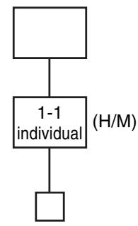
a) Single
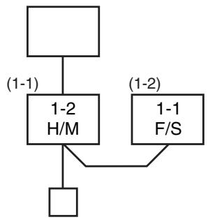
b) Twin
c) Double twin
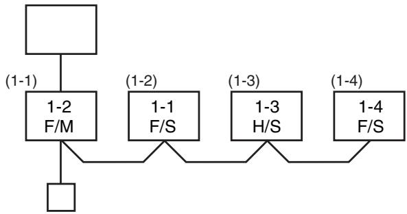
*** Turn ON the power. Address setting is completed automatically. ***
2) Group operation (multiple O / U = multiple indoor units with serial communication interface, no twin)

3) Multiple group operation
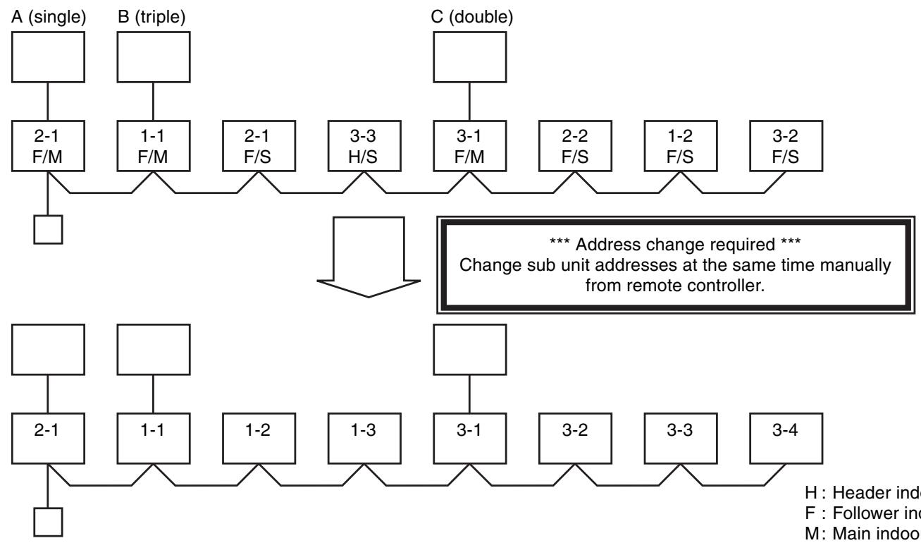
H:Header indoor unit
F : Follower indoor unit
M: Main indoor unit
S: Sub indoor unit
3. Address Setting
When determining indoor unit addresses with wiring completed without piping construction
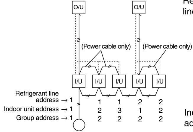
Wiring example of 2 refrigerant systems (Solid line: wiring, broken line: refrigerant piping)
For systems like this example, connect a wired remote controller independently without connecting R/C wires, and then set these addresses.
Group address
Individual: 0000
Header unit: 0001
Follower unit: 0002] in case of group control
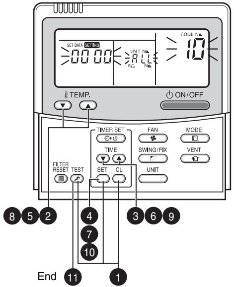
Operation procedure
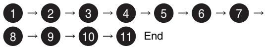
Manual setting by remote controller
- Connect a remote controller to the indoor unit whose address you want to set one to one. - Turn ON the power. Press TEST, SET, and CL on the R/C simultaneously for 4 seconds or more.  2 Set code 1 with TEMP. 2 buttons.  3 Set a refrigerant line address with TIME ④ buttons.  4 Press Indication on the LCD shows normal operation.  Set code 13 with TEMP. buttons.  6 Set indoor unit addresses with TIME ⑥ ⑧ buttons.  7 Press Indication on the LCD shows normal operation.  Group Set code with TEMP. 8 buttons.  9 Set indoor unit addresses with TIME ⑦ ④ buttons as follows: Individual=0000, header unit=0001, follower unit=0002  10 Press Indication on the LCD shows normal operation.  11 Press TEST. Indoor unit address setting is completed. The operation mode returns to normal OFF.ADDRESS SETTING (Continued)
■Checking location of indoor unit number
(1) To find the address of indoor unit whose location is clear
- In case of independent operation (1:1 connection of wired R/C and I/U) Perform the procedure during operation of indoor unit.(2) To find the location of indoor unit from its address
- When checking indoor unit number in the group. Perform the procedure while the indoor unit is not working. This procedure stops operation of all indoor units in the group.12. EXPLODED VIEWS AND PARTS LIST
High-Wall Type RAV-SM561KRT-E/RAV-SM801KRT-E | Location No. | Part No. | Description |
| 201 | 43T00048 | FRONT PANEL ASSY |
| 202 | 43T09340 | SUCTION GRILLE |
| 203 | 43T80014 | AIR FILTER (L) |
| 204 | 43T80013 | AIR FILTER (R) |
| 205 | 43T80003 | FILTER; FRAME |
| 207 | 43T03010 | BODY; RIGHT |
| 208 | 43T03011 | BODY; LEFT |
| 209 | 43T03012 | HIDE; CLAW |
| 210 | 43T09317 | LOUVER-H |
| 211 | 43T70001 | HOSE ASSY; DRAIN |
| 212 | 43T21302 | MOTOR;STEPPING |
| 213 | 43T44316 | REFRIGERATION ASSEMBLY (FOR SM561KRT-E) |
| 213 | 43T44317 | REFRIGERATION ASSEMBLY (FOR SM801KRT-E) |
| 216 | 43T11002 | PIPE-SHIELD (FOR SM561KRT-E) |
| 216 | 43T11002 | PIPE-SHIELD (FOR SM561KRT-E) |
| 217 | 43T19003 | FIX-P-SENSOR |
| Location No. | Part No. | Description |
| 218 | 43T49009 | SPRING |
| 219 | 43T49036 | PLATE; EVA-SEAL |
| 220 | 43T49039 | HOLDER; PLATE EVA-SEAL |
| 221 | 43T49038 | PLATE; EVA-SEAL |
| 222 | 43T49037 | HOLDER; PLATE EVA-SEAL |
| 223 | 43T79007 | GUIDE DRAIN |
| 224 | 43T39016 | FIX FOR MOTOR |
| 225 | 43T60075 | FAN MOTOR CORD |
| 226 | 43T21327 | MOTOR FAN |
| 227 | 43T20014 | FAN; CROSS FLOW |
| 228 | 43T22008 | M-B-BEARING |
| 229 | 43T39015 | BASE; BEARING |
| 230 | 43T03305 | BACK BODY ASSY |
| 231 | 43T07022 | HOLDER; PIPE |
| 232 | 43T82007 | PLATE; INSTALLATION |
| 233 | 43T85483 | OWNER'S MANUAL |
| 234 | 43T69309 | WIRELESS REMOCON; WH-H2UE |
| 235 | 43T83003 | HOLDER; REMOTE CONTROLLER |
| 236 | 43T62029 | COVER; TERMINAL |
| Location No. | Part No. | Description |
| 401 | 43T60047 | TERMINAL |
| 402 | 43T60320 | TERMINAL |
| 403 | 43T60321 | TERMINAL |
| 404 | 43T50308 | SENSOR HEAT EXCHANGER |
| 405 | 43T50306 | TEMPERATURE SENSOR |
| 406 | 43T69320 | TEMPERATURE SENSOR |
| Location No. | Part No. | Description |
| 407 | 43T60361 | FUSE |
| 408 | 43T09343 | E-PARTS BASE |
| 409 | 43T69424 | PC BOARD |
| 410 | 43T69427 | DISPLAY UNIT |
| 411 | 43T09344 | CORD CLAMP |