VSN990 - Monitor Datapath - Free user manual and instructions
Find the device manual for free VSN990 Datapath in PDF.

User questions about VSN990 Datapath
0 question about this device. Answer the ones you know or ask your own.
Ask a new question about this device
Download the instructions for your Monitor in PDF format for free! Find your manual VSN990 - Datapath and take your electronic device back in hand. On this page are published all the documents necessary for the use of your device. VSN990 by Datapath.
USER MANUAL VSN990 Datapath
natural_image
Illustration of server rack front panels with icons and a blue cover (no text or symbols)Table of Contents
Disclaimer/Copyright Statement....5
Quick Start Guide....6
Contents....6
Step 1 - Keyboard and Mouse....6
Step 2 - Connect Expansion Chassis (Optional)....7
Step 3 - Connect to a Network (Optional)....7
Step 4 - Connect Input Source....8
Step 5 - Connect Control Screen (Optional) and Monitors....8
Step 6 - Powering up the System....9
Step 7 - Windows®7 Setup....10
Step 8 - Activate Windows ^® 7....10
Step 9 - Display Setup....11
Step 10 - Wall Control (Optional)....12
Chapter 1 - Introduction....14
1.1 Introduction....1/4
1.2 Systems 14
1.3 How the User Guide is Organised....14
Contents
4.2 VSN990 / VSN1190 Chassis....21
4.3 SBC's....22
4.4 Backplanes....22
4.5 Backplane LED's 23
Chapter 5 - Cabling....25
5.1 Connecting the Keyboard and Mouse....25
5.2 Connecting an Expansion Chassis....25
5.3 Slots and Bandwidths - Optical Systems....29
5.4 Connecting to a Network....31
5.5 Connecting Input Sources....32
5.6 Connect Monitors and Control Screen (Optional) 32
5.7 Connecting Power Cables....34
Chapter 6 - Operation....35
6.1 Switching On....35
6.2 Initial System Boot on Delivery....35
6.3 Opening Wall Control (Optional) 37
6.4 Displaying Video Captures....38
Contents
Chapter 10 - Environmental....50
10.1 Certification and Compliances....50
10.1.3 Disposal....50
Chapter 11 - Specifications....51
11.1 Technical Drawings....51
11.2 Technical Specification - VSN970....52
11.3 Technical Specification - VSNogo....52
11.4 Technical Specification - VSNggoX....53
11.5 Technical Specification - VSN1170....53
11.6 Technical Specification - VSN1190....54
11.7 Technical Specification - VSN1100X....54
11.8 Technical Specification - Express9-G3....55
11.8.2 PCIe Port Width....56
11.9 Technical Specification - Express11-G3....57
11.9.2 PCIe Port Width....58
Chapter 12 - Warranty....59
Disclaimer/Copyright Statement
© Datapath Ltd, England 2016
Datapath Limited claims copyright on this User Guide. No part of this User Guide may be reproduced, released, disclosed, stored in any electronic format, or used in whole or in part for any purpose other than stated herein without the express permission of Datapath Limited.
Whilst every effort is made to ensure that the information contained in this User Guide is correct, Datapath Limited make no representations or warranties with respect to the contents thereof, and do not accept liability for any errors or omissions.
Datapath reserves the right to change specification without prior notice and cannot assume responsibility for the use made of the information supplied. Datapath Limited acknowledges all registered trademarks used within this User Guide.
Quick Start Guide
A version of the Quick Start Guide is included below for your convenience.
Contents
Main System
VSN Main chassis
Mouse/Keyboard
Recovery Media
Cables/Adapters
Accessories Pack
- Chassis Key
• MAC Address Labels
Expansion Unit
VSN Expansion chassis
ExCable/HLink card
Accessories Pack
- Chassis Key
- HLink-G3 Card
- SLink-G3 Card
- Ex-Cable-G3
Note: VSN Expansion units may have been purchased as part of a large system or ordered separately.
Each Datapath system is custom built therefore the number and type of input and output cards will differ from system to system.
Accompanying this Quick Start Guide are PCIe card product leaflets which give details on how the cards are installed and any accessories supplied with them.
Step 1 - Keyboard and Mouse
Quick Start Guide
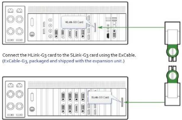
Step 2 - Connect Expansion Chassis (Optional)
text_image
HLink-G3 Card Connect the HLink-G3 card to the 5Link-G3 card using the ExCable. (ExCable-G3, packaged and shipped with the expansion unit.) 5Link-G3 CardStep 3 - Connect to a Network (Optional)
Quick Start Guide
Step 4 - Connect Input Source
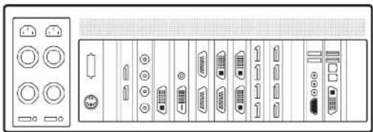
natural_image
Front panel of a computer tower showing various function keys and ports (no text or labels visible)Each Datapath system is custom built. The number and type of inputs will differ from system to system.
Contained within the documentation pack are PCIe card product leaflets which give details on how the cards are connected.
Step 5 - Connect Control Screen (Optional) and Monitors
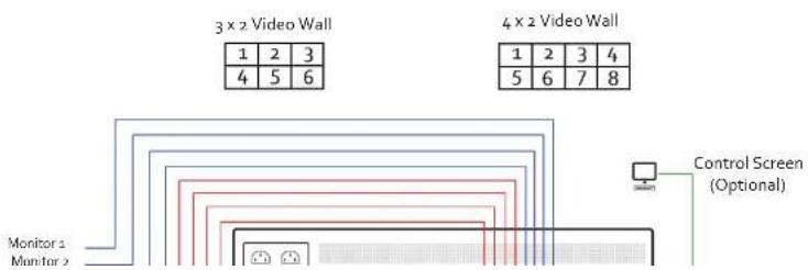
flowchart
graph TD
    A["Monitor 1"] --> B["3x2 Video Wall"]
    C["Monitor 2"] --> B
    B --> D["4x2 Video Wall"]
    D --> E["Control Screen (Optional)"]
    style A fill:#f9f,stroke:#333
    style C fill:#f9f,stroke:#333
    style B fill:#ccf,stroke:#333
    style D fill:#ccf,stroke:#333
    style E fill:#cfc,stroke:#333
Quick Start Guide
Step 6 - Powering up the System

1 Connect power cables then plug into a mains supply.
2 Switch on the power supply units.

text_image
Power F/U System Mode: 10000 Control Panel 3Quick Start Guide
Step 7 - Windows®7 Setup
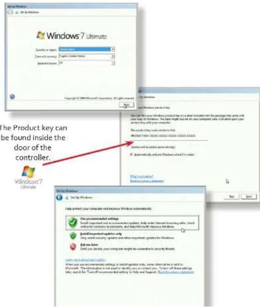
text_image
Windows 7 Ultimate Product key can be found inside the door of the controller. Windows 7 Ultimate Set Up Windows Help protect your computer and improve Windows automatically. Use programmed settings Install important updates, help make secret learning apps, check provide for solutions to products, and help Microsoft Improve Windows. Install important updates only Do you want security updates and other important updates for Windows. Ask me later Find you facile your computer might be available to security threats. Save our installed software When you are recommended settings, or installed updates only, some information is sent to Microsoft. The instructions not need to identify you or select you. You will also set these settings list, search for "Turn off implemented details" in Tools and Support. Find this update documentQuick Start Guide
Step 9 - Display Setup
All Datapath wall controllers have pre-configured settings for the wall layout and screen resolution. Change settings using the TWIN tab:

Start | Control Panel | Appearance and Personalization | Adjust screen resolution.

text_image
Change the appearance of your displays Display: 1. Generic PnP Monitor on Standard VGA Graphics Adapter Resolution: 1280 x 1024 Multiple displays: Extend desktop to this display This is currently your main display. Make text and other items larger or smaller What display settings should I choose? OK Cancel Apply Detect Identify Advanced settingsStep 10 - Wall Control (Optional)

Start | All Programs | Wall Control | Wall Control-My Computer
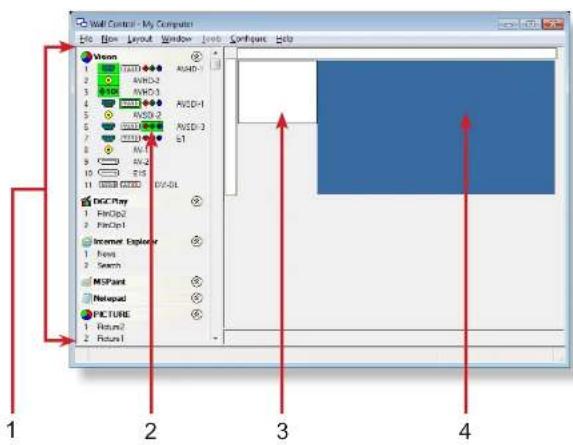
text_image
Wall Control - My Computer File Edit Layout Window Help Configure Help Vision 1 T200 AVCD-1 2 AVCD-2 3 AVCD-3 4 AVCD-4 5 AVCD-5 6 AVCD-6 7 AVCD-7 8 AVCD-8 9 AVCD-9 10 AVCD-10 11 AVCD-11 12 AVCD-12 13 AVCD-13 14 AVCD-14 15 AVCD-15 16 AVCD-16 17 AVCD-17 18 AVCD-18 19 AVCD-19 20 AVCD-20 21 AVCD-21 22 AVCD-22 23 AVCD-23 24 AVCD-24 25 AVCD-25 26 AVCD-26 27 AVCD-27 28 AVCD-28 29 AVCD-29 30 AVCD-30 31 AVCD-31 32 AVCD-32 33 AVCD-33 34 AVCD-34 35 AVCD-35 36 AVCD-36 37 AVCD-37 38 AVCD-38 39 AVCD-39 40 AVCD-40 41 AVCD-41 42 AVCD-42 43 AVCD-43 44 AVCD-44 45 AVCD-45 46 AVCD-46 47 AVCD-47 48 AVCD-48 49 AVCD-49 50 AVCD-50 51 AVCD-51 52 AVCD-52 53 AVCD-53 54 AVCD-54 55 AVCD-55 56 AVCD-56 57 AVCD-57 58 AVCD-58 59 AVCD-59 60 AVCD-60 61 AVCD-61 62 AVCD-62 63 AVCD-63 64 AVCD-64 65 AVCD-65 66 AVCD-66 67 AVCD-67 68 AVCD-68 69 AVCD-69 70 AVCD-70 71 AVCD-71 72 AVCD-72 73 AVCD-73 74 AVCD-74 75 AVCD-75 76 AVCD-76 77 AVCD-77 78 AVCD-78 79 AVCD-79 80 AVCD-80 81 AVCD-81 82 AVCD-82 83 AVCD-83 84 AVCD-84 85 AVCD-85 86 AVCD-86 87 AVCD-87 88 AVCD-88 89 AVCD-89 90 AVCD-90 91 AVCD-91 92 AVCD-92 93 AVCD-93 94 AVCD-94 95 AVCD-95 96 AVCD-96 97 AVCD-97 98 AVCD-98 99 AVCD-99 100 AVCD1 The Icons displayed in the application toolbar identify which type of source is available to each
Quick Start Guide
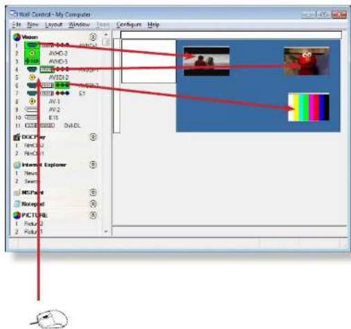
text_image
Wall Control - My Computer File New Layout Window Tools Configure Help Vision AVOD-2 AVOD-3 AVOD-4 AVOD-5 AVOD-6 AVOD-7 AVOD-8 AVOD-9 AVOD-10 AVOD-11 AVOD-12 AVOD-13 AVOD-14 AVOD-15 AVOD-16 AVOD-17 AVOD-18 AVOD-19 AVOD-20 AVOD-21 AVOD-22 AVOD-23 AVOD-24 AVOD-25 AVOD-26 AVOD-27 AVOD-28 AVOD-29 AVOD-30 AVOD-31 AVOD-32 AVOD-33 AVOD-34 AVOD-35 AVOD-36 AVOD-37 AVOD-38 AVOD-39 AVOD-40 AVOD-41 AVOD-42 AVOD-43 AVOD-44 AVOD-45 AVOD-46 AVOD-47 AVOD-48 AVOD-49 AVOD-50 AVOD-51 AVOD-52 AVOD-53 AVOD-54 AVOD-55 AVOD-56 AVOD-57 AVOD-58 AVOD-59 AVOD-60 AVOD-61 AVOD-62 AVOD-63 AVOD-64 AVOD-65 AVOD-66 AVOD-67 AVOD-68 AVOD-69 AVOD-70 AVOD-71 AVOD-72 AVOD-73 AVOD-74 AVOD-75 AVOD-76 AVOD-77 AVOD-78 AVOD-79 AVOD-80 AVOD-81 AVOD-82 AVOD-83 AVOD-84 AVOD-85 AVOD-86 AVOD-87 AVOD-88 AVOD-89 AVOD-90 AVOD-91 AVOD-92 AVOD-93 AVOD-94 AVOD-95 AVOD-96 AVOD-97 AVOD-98 AVOD-99 AVOD-100To open a video window click and drag an active capture into the Wall Control application.
Use the Help Menu for a comprehensive guide on the features of the Wall Control application.
Chapter 1 - Introduction
1.1 Introduction
Congratulations on your purchase of the Datapath Wall Controller system. The wall controller has been manufactured and tested to the highest standards offering unparalleled quality and reliability. The aim of this user guide is to assist you through the installation of the system safely and effectively and act as a reference guide for future use. Do not switch on the system until all the relevant cables have been connected.
1.2 Systems
The systems covered by this user guide are the VSN900 and the VSN1100 video wall controllers and expansion chassis ranges.
1.3 How the User Guide is Organised
The user guide is broken down into chapters and each chapter into sections. Chapters, sections and pages are numbered individually. Pages are numbered in Arabic numerals with the exception of the cover page (no numbering).
1.4 Fonts and Symbols
1.4.1 Fonts
The font used throughout the user guide is Corbel however the following font styles mean:
Bold = Used to describe menu titles, buttons in software or elements that you must type exactly as shown in the Command Line Interface
Ellipsis (...) - Parameter that can be repeated several times in a command line.
Between brackets ([]) - Optional items.
Between braces ( ) - Set of choices (separated by I) from which you must choose only one.
Italic = Information that must be supplied by the user
C. ·s 1. ·s 2. Indicatex code or process output
1.5 Terminology and Definitions
1.5.1 Backplane
Datapath manufactures types of backplanes; the Express9 Gen 3 (9 slots) and the Express11 Gen 3 (11 slots). The Express 9 Gen 3 is used in the VSN970/990 and the VSN900X expansion chassis and the Express 11 Gen 3 is used in the VSN1170/1190 and the VSN1100X expansion chassis.
The backplanes use advanced PCI Express switches to create a high bandwidth fabric that connects up to 9 or 11 PCI Express plug in cards in a single system. This system can be expanded to create more PCI Express slots using the VSN900X/1100X expansion units.
1.5.2 BIOS
Basic Input/Output System: Used during system boot up to initialise and test system hardware and load the operating system. Each BIOS is specifically designed to work with a particular motherboard.
1.5.3 Command Line Interface
Preferred means by advanced users of issuing commands and controlling an application or operating system. Programs with a Command Line Interface are generally considered easier to automate via scripting.
1.5.4 Control Screen
Some systems are shipped with the BIOS configured to boot the system off the onboard graphics device. This output can then be used as the Control Screen for a typical video wall. The content of the control screen is not displayed on the video wall desktop and can be used to host the Wall Control application window.
1.5.5 SBC
A Single Board Computer built on a single circuit board. SBC's in the VSN970/990/1170/1190 are plugged into the PICMG1.3 slot on the Express9 and Express 11 backplanes
Chapter 2 - Safety

2.1 Safety Precautions
To prevent damage to your Datapath product or injury to personnel operating the equipment, please read the following safety precautions prior to operation. These instructions should be made available to all those who will use and operate Datapath products.
2.1.1 Power Supply
All Datapath products require a mains power supply. This power supply must be disconnected when equipment is being upgraded or relocated.
2.1.2 Cables
Do not expose cables to any liquids; doing so may cause a short circuit which could damage the equipment. Do not place heavy objects on top of any cables as this can cause damage and possibly lead to exposed live wires.
2.1.3 Ventilation
All computer equipment should be located in a well ventilated area. All ventilation holes on the computer casing must be kept clear of any obstruction at all times. Failure to do so will result in the system over heating and damaging your equipment.
2.1.4 Working Environment
The equipment should be located in an environment free from dust, moisture and extreme changes in temperature and should be placed on a stable and solid work surface. Liquids (hot/cold drinks etc) should not be placed near the equipment as spillage could cause serious damage.
2.1.5 Gas/Flammable Liquids
Electronic equipment should never be used in the presence of gas or any flammable liquid, doing so could result in an explosion or serious fire.
2.2 Rack Mount Safety Instructions
2.2.1 Temperature
If VSN900/1100 systems are to be installed in a closed or multi-unit rack assembly, the installation should be such that the amount of air flow required for safe operation of the equipment is not compromised. The operating ambient temperature of the rack environment should be maintained below 35 degrees centigrade under all conditions. Appropriate cooling arrangements should be built into the cabinet to ensure that this specification is maintained.
2.2.2 Mechanical Loading
Mounting of the equipment in the rack should be such that a hazardous condition is not achieved due to uneven mechanical loading.
2.2.3 Circuit Overloading
Consideration should be given to the connection of the equipment to the mains supply circuit and the effect that overloading of the supply might have on any over-current protection or supply wiring. Appropriate consideration of equipment nameplate ratings should be used.
2.2.4 Reliable Earthing
Reliable earthing of all rack-mounted equipment should be maintained. Particular attention should be given to supply connections other than direct connections to the branch circuit (e.g. use of power strips).
2.3 Unpacking and Initial Inspection
2.3.1 Unpacking
The system is heavy; lifting precautions should be considered.

To unpack the system follow the instructions provided on the outside of the packaging. All packaging materials should be retained for future transit.
Chapter 3 - General
3.1 Overview
Datapath's VSN900 and VSN1100 systems are powerful video wall controllers, capable of delivering Ultra High Definition video across large, multi-screen display installations. For use in a host of environments, from CCTV security suites to sports stadia, and from military installations to utility management centres. Fully compatible with Datapath's world leading portfolio of PCI Express video capture and graphics cards that offer Ultra High Definition video for storage and display, including the ability to capture HDCP sources without any display restrictions.
Each system has been designed for use in demanding control room environments. Each component has been subjected to rigorous testing to ensure the highest levels of performance and reliability.
In summary:
• High performance and reliability in demanding conditions
- Suited for 24/7 applications
- Can be operated via a network
- PCIe switched fabrics enables systems to be expanded using additional expansion chassis
• Wall Control software (optional) - Display video on the desktop in real time using an array of features
• Wall Monitor software (optional) - Provides monitoring of the temperature and voltage sensors on system components
3.2 Systems in the VSN900 and VSN1100 Range
| Features | ||||||||
| Systems | Express 9 Backplane | Express 11 Backplane | SBC 3 | SBC 4 | Intel® Core i7 | Dual Intel® Core Xeon | RPSU ATX | |
| VSNg70 ^⓹ x x x x | x x | |||||||
| VSNggo x x x x | ||||||||
General
| VisionRGB-E1s Single channel HD video capture card. |
| VisionAV Single Channel HD and single channel SD video capture card. |
| VisionRGB-E2s Dual channel HD video capture card. |
| VisionDVI-DL Single channel Dual-Link video capture card. |
| VisionSD4+1s Video capture card with four channels of 5D and one of HD. |
| VisionSDI2 Dual channel HD-SDI video capture card. |
| Vision5D8 Eight channel SD video capture card. |
| HLink-G3 Host link card for Gen.3 expansion systems. |
| SLink-G3 Slave link card for Gen.3 expansion systems. |
| ExCable-G3 Copper cable Gen.3 for expansion systems. |
| HLink-Optical Host link card for optical linked expansion system. |
| SLink-Optical Slave link card for optical linked expansion system. |
| ExCable-Optical Locking optical cable available in 50m and 100m lengths. |
We are constantly updating our product portfolio, for the latest details on our full product range please visit our website: www.datapath.co.uk
3.4 Product Datasheets
Product datasheets are available to download from www.datapath.co.uk
Chapter 4 - Hardware
4.1 VSN970/VSN1170 Chassis
4.1.1 Front
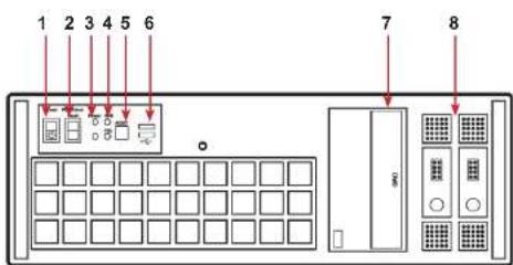
text_image
1 2 3 4 5 6 7 8Front Panel
| 1= Power, on-off 5= Reset Button | |
| 2= PSU Alarm Reset 6= USB | Ports |
| 3= Power LED 7= DVD +RW | |
| 4= HDD LED 8= Removable | Hard Drives |
4.1.2 Rear

text_image
R1 R2Hardware
4.2 VSN990/VSN1190 Chassis
4.2.1 Front
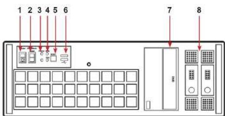
text_image
1 2 3 4 5 6 7 8Front Panel
| 1 = Power on-off 5= Reset | Button |
| 2= PSU Alarm Reset 6= US | B Ports |
| 3= Power LED 7= DVD +RW | |
| 4= HDD LED 8= Removable | Hard Drives |
4.2.2 Rear
R1
R2
4.3 SBC's
Datapath have developed, tested and qualified two SBC's for use in the VSN900/1100 range of video wall controllers providing improvements to the BIOS and a higher performance for Windows based software applications.
4.3.1 SBC3
The Portwell ROBO 8120VG2R:
- An Intel® Xeon® processor based on PICMG 1.3 SHB with DDR3 ECC SDRAM.
• Used in the VSN990 and the VSN1190.
4.3.2 SBC4
The Portwell ROBO-8112 Q87:
- An Intel® Core i7 processor based on PICMG 1.3 SHB with DDR3 SDRAM.
• Used in the VSN970 and the VSN1170.
4.4 Backplanes
The Datapath backplanes use advanced PCI Express switches to create a high bandwidth fabric for connecting multiple PCI Express into a system.
4.4.1 Express9-G3
- Nine slot PCI Express backplane - 8 x 4 lane slots, 1 x 8 lane slot and 1 x PICMG 1.3 slot.
• Used in the VSN970, VSN990 and the VSN900X.
Hardware

natural_image
Green printed circuit board with multiple black connectors and a purple patch (no visible text or symbols)Express11-G3
4.5 Backplane LED's
Both the Express9-G3 and the Express11-G3 backplanes have a LED's fitted for each PCI Express slot and the PICMG1.3 slot. The LED's indicate the following:
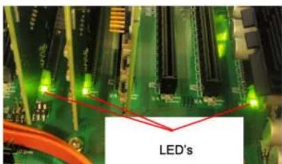
text_image
LED's4.5.2 Express11-G3
| D1 ON = +32V supply present |
| D2 ON = +33V supply present |
| D3 ON = +5V supply present |
| D4 ON = +5V Standby supply present |
| D5 ON = PICMG link speed = G3, FLASH-FAST = G2, FLASH-SLOW = G1 |
| D6 ON = PCe Slot 1 link speed = G3, FLASH-FAST = G2, FLASH-SLOW = G1 |
| D7 ON = PCe Slot 2 link speed = G3, FLASH-FAST = G2, FLASH-SLOW = G1 |
| D8 ON = PCe Slot 3 link speed = G3, FLASH-FAST = G2, FLASH-SLOW = G1 |
| D9 ON = PCe Slot 4 link speed = G3, FLASH-FAST = G2, FLASH-SLOW = G1 |
| D10 ON = PcIe Slot 5 link speed = G3, FLASH-FAST = G2, FLASH-SLOW = G1 |
| D11 ON = PcIe Slot 6 link speed = G3, FLASH-FAST = G2, FLASH-SLOW = G1 |
| D12 ON = PcIe Slot 7 link speed = G3, FLASH-FAST = G2, FLASH-SLOW = G1 |
| D13 ON = PcIe Slot 8 link speed = G3, FLASH-FAST = G2, FLASH-SLOW = G1 |
| D14 ON = PcIe Slot 9 link speed = G3, FLASH-FAST = G2, FLASH-SLOW = G1 |
| D15 ON = PcIe Slot 10 link speed = G3, FLASH-FAST = G2, FLASH-SLOW = G1 |
| D16 ON = PcIe Slot 11 link speed = G3, FLASH-FAST = G2, FLASH-SLOW = G1 |
| D17 ON= PLX Fatal Error |
| D24 ON = PSU FAULT |
No LED's flashing indicates that lane width has not been established. The LED's will not flash on slots where no cards are installed.
Chapter 5 - Cabling
This Chapter will cover:
- Connecting keyboard and mouse
- Connecting an expansion chassis
- Connecting to a network
- Connecting input sources
- Connecting a control screen
- Connecting monitors
- Connecting power cables
5.1 Connecting the Keyboard and Mouse
The keyboard and mouse supplied with your system both have a USB interface. Identify vacant USB ports on the chassis and plug them in.

The location of the USB ports are identified here
5.2 Connecting an Expansion Chassis
The Datapath range of expansion chassis are solutions that allow system builders and integrators the flexibility to extend a PCIe based PC or motherboard enabling a larger, distributed system architecture. The optical expansion chassis can be used to create systems with distances of up to 100m between the host PC and the expansion chassis.
The expansion link is created using a combination of Host Link (HLink) and Slave Link (SLink) cards connected together using a cable or a series of cables (copper or optical). These combined provide a high bandwidth PCI Express link from an upstream host to a distributed expansion unit.
Cabling
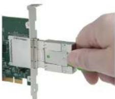
Connect the HLink-G3 and SLink-G3 using the ExCable-G3 provided.
natural_image
Hand inserting a card into a network interface on a green circuit board (no text or symbols visible)The correct way to insert the cable is to have the release tab facing away from the card. The rectangular connector needs to be fully inserted into the card until a definite click can be heard. This locks the cable in place. Failure to lock the connector in place can result in the ExCable-G3 becoming separated from the card and the link between chassis being lost.
natural_image
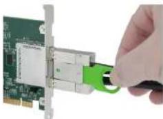
Hand inserting a green USB into a network card (no text or symbols visible)To remove the connector gently pull the ring pull tab to unlock the connector from the card then slide the connector out fully.
Normal copper cable handling precautions should be observed to avoid tight loops or kinks in the ExCable-G3.

If more than one expansion chassis is supplied, ensure the cards are paired correctly by connecting the cards labelled "Links" together, the pair labelled "link2" together and so on. In the event that this is not possible i.e. the expansion chassis are shipped separately and the cards are not labelled, connect the cards using the ExCables-G3 provided and re-install the Datapath Driver Install package to reset the pairings.
5.2.1 Connecting the VSN900X-Optical and the VSN1100X-Optical
The Datapath optical solution allows expansion chassis to be located up to 100m away from the main controller. The Optical solution can support up to PCIe Gen 3 x8 bandwidths between an HLink-Optical, located in the host machine and an SLink-Optical, located in the expansion chassis. Full bandwidth is achieved by using two ExCable-Optical cables between each HLink and SLink-Optical card.
Alternatively, PCIe Gen3 x4 bandwidth can be achieved using only one ExCable-Optical between each HLink-Optical and SLink-Optical. This will reduce the total amount of video signal that can be transferred between the chassis. If x4 bandwidth is acceptable, one HLink-Optical can be connected to two SLink-Optical cards, providing that the HLink-Optical is located in a x8 slot.
See creating a PCIe x4 lane and x8 lane link

If your optical expansion chassis is supplied as part of a complete wall controller system the HLink-Optical card will be pre-installed in the host machine which contains the SBC. If the expansion chassis has been supplied separate to a host machine, the HLink-Optical card provided needs to be installed in the host PC.
You are likely to need a flat blade and/or a cross head screwdriver for the installation of the HLink-Optical card. Power down the PC (including peripherals), switch off at the mains and disconnect all the cables connected to the computer and expansion chassis. Remove the PC cover. Locate a vacant PCIe slot (x8) on the motherboard and remove the backing plate (retain all screws).
Remove the HLink-Optical card from its packaging and secure it firmly into the empty PCIe slot. Screw the bracket to the back panel of the PC and replace the cover.
If more than one expansion chassis is supplied, ensure the cards are paired correctly by connecting the cards labelled "Link1" together, the pair labelled "link2" are connected together and so on. In the event that this is not possible i.e. the expansion chassis are shipped separately and the cards are not labelled, connect the cards using the ExCables-Optical provided and re-install the Datapath Driver Install package to reset the pairings.
5.2.1.1 Connecting to a VSN1170 and VSN1190
If the VSN1100X-Optical is being connected to a VSN1170 or VSN1190 the full bandwidth (x8) is available in all PCIe slots. When
Cabling
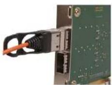
natural_image
Close-up of a green electronic circuit board with an orange cable inserted, showing internal components and wiring (no visible text or symbols)The rectangular connector needs to be fully inserted into the card until a definite click can be felt. This locks the cable in place. Failure to lock the connector in place can result in the ExCable-Optical becoming separated from the card and the link between chassis being lost.
Normal fibre handling precautions should be observed to avoid tight loops or kinks in the ExCable-Optical. Bend radii below 75mm are not recommended and may result in fibre breakage.

natural_image
Close-up of a hand connecting a black cable to a circuit board (no visible text or symbols)To remove the connector gently pull the ring pull tab to unlock the connector from the card then slide the connector out fully.
5.2.2 Creating the PCIe Link - x8 (Optical)
For maximum bandwidth, the HLink \SLink -Optical cards should be connected using two optical cables to form an eight-lane ("x8") link, capable of 64G-transfers/sec (approx 6.4GB/s effective data rate in each direction).
In "v8" mode the lumener link "12" on the HI ink. Optical card must be set to position 3.5 as shown below
Cabling
5.2.3 Creating the PCIe Link - x4 (Optical)
For a reduced bandwidth connection or where a single HLink-Optical is used to connect to two separate SLink-Optical cards (i.e. "Star" connection of two expansion chassis). In this configuration, for a single ExCable-Optical link the PCIe connection is "x4" and the bandwidth is reduced to 3.2GB/s.
In "x4" mode the Jumper Link "J7" on the HLink-Optical card must be set to position 1-2 as shown below.
Either (or both) connectors on the HLink-Optical card can be used, but only the top connector of the SLink-Optical card.
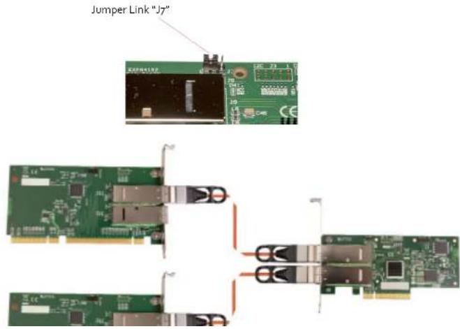
text_image
Jumper Link "J7"Cabling
5.3.1 VSNgoo Range - Optical Expansion
| HOST EXPANSION | ||||||||
| PCIe Slot Number | Bandwidth Ex Cable Optical HLink Optical SLink Optical | |||||||
| X8 X4 1 Cable 2 Cables | Top Connector | Bottom Connector | Top Connector | Bottom Connector | ||||
| 1 x x x x x (1) | ||||||||
| 1 x | x | x | x (2) | |||||
| 2 | N/A | x | x | x | x | |||
| 3 | N/A | x | x | x | x | |||
| 4 | N/A | x | x | x | x | |||
| 5 | N/A | x | x | x | x | |||
| 6 | N/A | x | x | x | x | |||
| 7 | N/A | x | x | x | x | |||
| 8 | N/A | x | x | x | x | |||
| 9 | N/A | x | x | x | x | |||
(1) SLink-Optical card is pre-installed in the PICMG 1.3 slot in the expansion chassis.
(2) Two ExCables-Optical connecting to two separate SLink-Optical cards (see section: Creating the Link -x4 optical on page 29)
5.3.2 VSN1100 Range - Optical Expansion
| HOST EXPANSION | ||||
| PCIe-Slot | Bandwidth | ExCable-Optical HLink | Optical | SLink-Optical |
Cabling
5.4 Connecting to a Network
The optional Wall Control software enables the user to operate and manage the video wall display remotely, via a network. The SBC4 has two LAN ports, plug in your network cable (not supplied) to a LAN port and connect the wall controller to the LAN, as shown below:
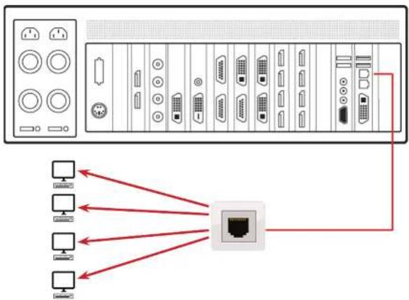
It should be noted that network ports have a potential vulnerability. If your system is working in a secure environment you
5.5 Connecting Input Sources
Each system is custom built and each controller will differ depending on the number and models of input cards installed. The packing list enclosed with your system will enable you to establish which input cards you have installed in your wall controller.
Contained within the product documentation folder are PCIe card product leaflets which give details on how the cards are installed and any accessories which may accompany them. For detailed information on specific cards please consult the relevant User Manual. Each capture card manual can be located on the Datapath Recovery Media supplied with your system.
5.5.1 Cable Handling

Great care must be taken when connecting cables. Ensure the cable connectors are the correct type for the connector on the cards. Push the cable connector on squarely, there is no requirement to force the connector in place. Poor cable handling could result in damaged pins in the cable connector, this in turn could cause serious and irreversible damage to the printed circuit board. Any damage caused this way is not covered under the warranty.
5.6 Connect Monitors and Control Screen (Optional)
Each system could support any number of screens from 4 to 64 depending on hardware, however the following information is a guide based on a 12 screen 4x3 video wall system.
The number of graphics cards in your system determines how many screens will be available on your video wall. The ImageDP4 graphics cards each support a maximum of 4 screens, one output per screen.
5.6.1 Screen Order
The screen order is determined by where the graphics cards are installed in the system. The card installed nearest to the SBC is card 1 which is the first card to be initialised and will generate the desktop for the top left monitor on the video wall plus the 3 adjacent screens. The second card drives the next four screen and so on. Each graphics card has 4 connectors, numbered as follows:
Cabling
Connect the graphic outputs to your monitors using DisplayPort cables. (Not supplied)
Twelve Screen Display Wall
| 1 2 3 4 | |||
| 5 | 6 | 7 | 8 |
| 9 | 10 11 12 |

text_image
9 10 11 12 5 6 7 8 1 2 3 4Corresponding Graphics Outputs
Cabling
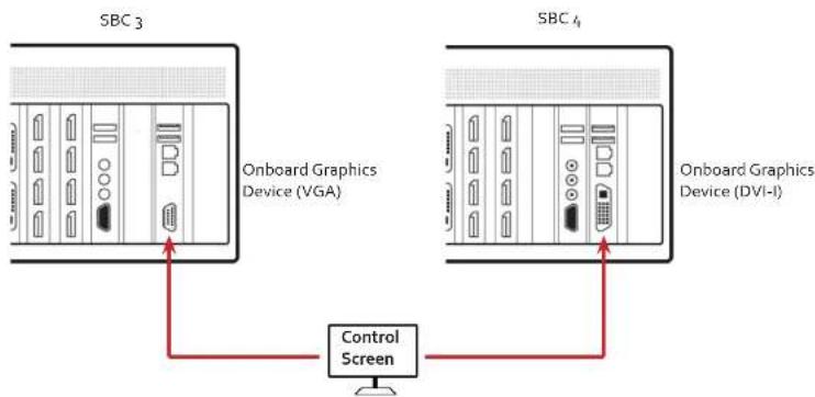
flowchart
graph TD
    A["SBC 3"] -->|Onboard Graphics Device (VGA)| B["Control Screen"]
    C["SBC 4"] -->|Onboard Graphics Device (DVI-I)| B
5.6.4 How to disable the Control Screen
If you do not require a control screen then you should disable the integrated graphics in the system BIOS. (See Chapter 13 - Use of the SBC's Onboard Graphics Device).
5.7 Connecting Power Cables
This section applies to both the RPSU and the ATX powered systems and expansion chassis.
Chapter 6 - Operation
This chapter will cover:
- Switching on
- Initial system boot on delivery
- Setting up the operating system
- Opening Wall Control
- Displaying video captures
6.1 Switching On
When switching the system on for the first time you will need to complete the initial system boot steps as described in Initial System Boot on Delivery below.
6.1.1 Switching on the Main System
All systems are supplied with either RPSU or ATX power supplies, see System Features for details.
- Switch on the power supply units ensuring both units on the RPSU are switched on.
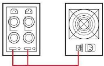
natural_image
Two electronic devices with labeled ports and wiring, connected by a red line (no text or symbols present)Operation
6.2.1 Select Language Pack
You will now be prompted to set up your Windows® 7 operating system starting with selecting the language option you require. Language selection is the responsibility of the customer and is not part of the system pre configuration prior to shipment. Windows® 7 language settings can be changed using Control Panel/Region and Language on the Keyboard and Languages tab. Language packs are available to download as optional updates through Windows Update. The following languages are pre-installed:
- Simplified Chinese
- English (UK)
- English (USA)
- French
• German
• Italian - Japanese
- Polish
- Portuguese (Brazilian)
• Russian - Spanish
6.2.2 Select Country and Region

Operation
6.2.4 Enter the Product Key
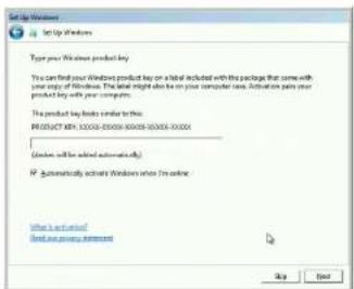
text_image
Set Up Windows Type your Windows product key You can find your Windows product key on a local included with the package that come with your copy of Windows. The key might also be on your computer now. Activation plans your product key with your computer. The product key looks similar to this: P.O.O.UCT 90K: 10000-20000-60000-80000-00000 (Windows will be added automatically) IP Automatically activate Windows when I'm online: What is an option? Find any previous statement Up NextEnter the Product key in the edit box, the Product Key is attached to the front panel of your system.
Once the Product key has been entered, read and accept the license agreement.
6.2.5 System Backup
It is strongly recommended that you create some form of system recovery media using the MS Windows Backup and Restore Tool once your system is up and running. This will enable you to restore to factory settings should serious problems occur.

Start | Control Panel | System and Security | Backup and Restore
6.3 Opening Wall Control (Optional)
Wall Control is an optional video/display wall management software application specifically designed for Datapath Wall Controllers. Wall Control consists of two separate elements that work together to enable you to control the display wall, the Wall Control Application and the Wall Control Server.
6.3.4 Wall Control
Selecting Wall Control will launch the application window but will not connect to a Wall Control Server. For more information regarding connecting to a Wall Control Server, consult the application help file.
6.4 Displaying Video Captures
Once a connection to a Wall Control-red server has been established then windows can be created for display on your video/display wall. Some video formats may not be supported, see Installing video CODECS in the Advanced User Chapter.
Windows can be created using the New menu or the application Toolbar.
6.4.1 New Menu
Displays options for each window type:
Preset Window
Vision Window
IP-Camera Window
Run an Application
6.4.2 Toolbar
The application Toolbar displays a list of the type of windows that can be opened, depending on the hardware you have installed in your machine.
To open the required inputs:
Select the required input using the cursor and drag to a preferred position on the wall.
Double click on the required input and the window will open, positioned at the top left of the display wall.
Open multiple inputs by pressing the shift key and clicking the required number of inputs with the mouse.
Chapter 7 - Software
This chapter will cover:
- Wall Control
- Wall Monitor
- Utilities
7.1 Wall Control (Optional)
The optional Wall Control software application (Wall Control-red / Wall Control-SOX depending on your order) is pre-installed and tested prior to shipment of your system therefore no installation of the software is required.
Wall Control displays the desktop of the machine that is being controlled. It allows you to remotely display Vision, IP-Camera (Wall Control-SQX required) and Application windows across a network on another machine or locally on the same machine.
You can use Wall Control to interactively move, size and position application windows and control Vision and IP-Camera windows by using the Windows Properties sheet. Wall Control also has a guide and grid function to aid the positioning of windows on the display wall.
Wall Control allows you to save specific wall layouts as .lay files enabling them to be re-called when required.
There is an area of the application around the desktop where windows can be dragged allowing them to be manipulated without being displayed on the video/display wall.
7.1.1 Icons displayed in the Wall Control Toolbar
The Icons displayed in the application toolbar identify which type of source is available to each input:
| Composite Source. | |
| S-Video Source. | |
| Analogus Source. |
7.1.4 Offline Configuration
The Wall Control offline layout editor allows layout files to be created and edited without physically displaying any windows on the display wall. Wall Control can be connected offline on either the server machine or a machine without any display wall hardware, for example a laptop.
An offline connection in Wall Control is initiated by opening a configuration file. This file must have been exported from a server machine and will contain a snapshot of the hardware and software configuration on that machine.
7.1.5 Vision and IP Window
Control over presenting captured video and IP camera streams on the display wall. Configure window properties including:
- Position and size of windows
- Aspect ratio enforcement
- Exclude window borders and menu bar
- Create on screen display captions
• Control capture rate
7.1.6 Application Windows
Support for controlling applications such as Internet Explorer, Microsoft Powerpoint. Application can be opened direct from the Wall Control Toolbar, through the Command Line Interface or from previously saved layout files.
7.1.7 On Screen Display (OSD)
Highly configurable OSD function to overlay bitmaps (not on all types of window) and text over Vision and IP-Camera windows. Add descriptions and logos with transparency support and create specific display variables such as frame rates.
7.1 & Carousel Support
7.1.12 Support for Crestron /AMX Controllers
- Remote Command Line Interface for automation via Crestron/AMX Controllers:
• Control the display wall remotely from a Crestron/AMX controller - Access to the full local Command Line Interface
• Support for RS-232 (via serial cable) and TELNET (via a local network) - Integrated user interface support to configure and monitor the Remote Command Line
7.2 Wall Monitor (Optional)
The optional Wall Monitor software application enables you to monitor the temperatures and voltages of the following system components:
- Backplanes
- Capture Cards
- SQX Cards
• SBC - CPU Cores
- Graphics Cards
Should any overheating or voltage surge be imminent within the system, the Wall Monitor application will alert the user via a pre-configured alarm.
When running, the Wall Monitor application can display a transparent floating icon which can be placed anywhere on the desktop.
Software
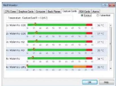
bar
Wind Monitor | Processor | Temperature Range (°C) | |---|---| | 2t VisionAV-SDL | 36°C | | 2t VisionAV-SDL | 37°C | | 2t VisionAV-HD | 37°C | | 4t VisionAV-HD | 35°C | | 8t VisionAV | 34°C | | 8t VisionSC-CPE | 35°C |7.2.2 Wall Monitor Application Window
The Wall Monitor application window (above) is displaying the temperature of the capture cards in the system. To view different components, click on the relevant tabs of the application. Temperatures can be displayed in either degrees Fahrenheit or degrees Celsius.
7.2.3 Configuring Alarms
Wall monitor allows you to configure three types of alarm to warn of impending problems:
System Buzzer - The system buzzer can be configured to determine the amount of time the buzzer will be audible up to a maximum of 5 seconds, an audio alarm is activated within the system. On some systems, speakers may have to be connected.
Email - Should you not be in the proximity of your system and email warning can be configured. An email is sent to a nominated email address giving details of impending problems.
On Screen - Text is displayed on screen to warn of impending problems with the system. The Wall Monitor icon adopts an amber harder when the alarm is issued
7.3 Vision Application (Optional)
When purchased separately, Vision capture cards are supplied with a powerful software application for configuring the format of input sources and displaying the data.
7.3.1 Video Streaming
DirectShow drivers for WDM Streaming driver supports the following applications, to encode, record and stream video over networks or the Internet:
• Microsoft Media Encoder®
• VLC
- VirtualDub
• Any other DirectShow encoding software
For streaming applications, Vision cards can be used with Windows Media Encoder to compress and stream captured video. To replay the video, use Windows® Media Player.
Any application compatible with Windows® DirectShow technology can use Vision capture cards due to their built-in WDM support.
7.3.2 Vision Software Capabilities
Timestamp support for streaming synchronisation:
- Synchronisation of multiple inputs across multiple cards
• Synchronise systems using network clock synchronisation - For edge blending and other applications
Software
- DirectShow interface
• The RGBEasy API for advanced audio and video control - Fully integrated for use with Datapath Wall Control software for video wall applications
7.3.3 MultiStream
Datapath's MultiStream feature is available on all Datapath capture cards and enables multiple, independently formatted video streams to be set up in parallel.
Each stream can be formatted completely independently and individual selection of resolution, colour space and cropping region can be set for each stream. This maximises bandwidth utilisation of the capture card and PCIe interface, and also simplifies development tasks for application developers who do not need to implement video stream reformatting separately.
7.3.4 Vision Application Overview
The application displays the connected source in a window; it has the following features:
- Scales the data to fit in the window
- Ability to set up sources accurately (settings automatically saved)
- Save a single frame to a file in one of the following formats: BMP, JPEG, GIF, TIFF, PNG
- Print a single frame
- Maintain the aspect ratio of the displayed captured data
- Cropping
- Display text over the data (on-screen display)
- Command line interface
7.4 Software Utilities
Datapath provides a group of software utilities designed to assist you fine tune your system for specific individual system requirements. All the software utilities can be found on the Recovery Media that was shipped with your system, alternatively, you can download the most up-to-date versions from the Datapath website.
7.4.1 Desktop Utility
Used to define a desktop resolution which can compensate for display bezels or projector overlap.
7.4.2 Custom Mode Utility
A utility for defining custom display timings for video modes not available in the display driver or EDID.
7.4.3 Multi Resolution Configuration Tool (MultiResConfig)
Developed to assist in the design and configuration of a video wall that contains a mixture of multi resolution displays.
7.4.4 Diagnostic Tool (diagtool)
A diagnostic tool that gathers information to assist in diagnosing problems with hardware and software configurations. Information is gathered and compressed into a zip file for onward transmission to the Datapath Support Team.
7.4.5 PCICFG Tool
A diagnostic program that prints out the PCI configuration information. Note, this tool must be run from either a USB or MSDOS boot disk, it cannot be run from Windows ^® .
7.4.6 Sleep Utility
Designed to generate a pause within a script. This can be used when sequencing the loading of files or application windows.
Chapter 8 - Troubleshooting
8.1 Frequently Asked Questions (FAQs)
8.1.1 I can't Save a Layout file?
The server does not have a USB License Dongle installed and so Wall Control is working in limited Demo mode.
8.1.2 Access is denied
This message means that the attempt to connect to the server application failed because the authentication information provided was not acceptable.
One of the following has occurred:
The user name, the password or the machine/domain that you have entered are not correct. Try entering the details again.
If the machine to which you are connecting is running Windows XP Service Pack 2 and you have not entered a password, you will need to change your account so that you have a password.
If the machine you are connecting to is running Windows XP and it is not participating in a domain, you will need to change the Network Authentication settings on the machine.
8.1.3 RPC Server Unavailable
This message means that the attempt to connect to the server failed.
If you are connecting to My Computer:
Is the server application running?
Did an error occur that prevented the server application starting the RPC server?
Are you using the correct port name?
If you are connecting across a network:
8.1.4 The endpoint is a duplicate
This error message suggests that an attempt to open a communication port failed because it is already in use.
If the Wall Control server has not been activated or the networking has been disabled in the Wall Control Administrator dialogue or Wall Control has not been activated, the problem is with the port name.
If networking is enabled, the problem could be with either the port number or the port name.
You can find out the port number and the port name that the server application is using through the Server Application Manager dialogue or the application event viewer.
You can find out which port numbers are in use on a machine with the netstat command. There is no way to find out which port names are in use.
Use Wall Control | Configure Menu | Server Application Manager to change the port number and/or port name and restart the server application.
8.1.5 The remote procedure call failed and did not execute
This is displayed when trying to contact a server application that has been stopped after it had been connected to successfully. Go to the Server Application Manager dialogue and start the server application again.
8.1.6 Changing Screen Resolution
Prior to making any changes to the resolution, it is recommended that the Vision server be stopped beforehand. This can be done using Wall Control | Configure Menu | Server Application Manager.
The servers retain resources on the graphics card which may not be available if the resolution is changed.
8.1.7 How do I connect a remote command controller via RS-232 or IP-Telnet? E.G. Crestron or AMX controllers.
Support for RS-232 and IP remote control of Datapath machines is provided through our Wall Control RED software. This
Full information on usage of the Remote command line interface can be found in the Wall Control help file by either searching for 'remote command line' or pressing the 'Help' button on the 'Remote Command Line' dialogue itself.
8.1.8 When I recall a Fire Fox or Chrome web browser page, the window is not positioned where I saved it?
Wall Control only supports Internet Explorer. Full functionality is not available using any other web browser.
8.2 Technical Support
Registered users can access our technical support using email and the Support Enquiry Form on our website, usually with a response within 24 hours (excluding weekends).
8.2.1 Email
Send an email to support@datapath.co.uk with as much information about your system as possible. To enable a swift response our support team will need to know the following details:
- Specification of the PC - including processor speed.
- Operating system.
- Application Software.
• Datapath Hardware/Software. - The exact nature of the problem - please be as specific as possible.
Please quote version and revision numbers of hardware and software wherever possible.
8.2.2 Support Procedures
During the support process you may be asked by one of our support staff to carry out certain tasks and procedures to assist them in solving any problem you may encounter. Details and up to date instructions can be found in the support section of the Datapath website.
Chapter 9 - Maintenance
9.1 Filter Maintenance
The system filter is an integral part of the wall controller and as such it needs to be maintained correctly. Failure to maintain the filter can result in the system overheating and causing it to fail. In normal operating conditions the filter should be removed and cleaned every 3 months. However, this 3 month period is a guide only and it can be increased to every 6 months or decreased to one month depending on the levels of dust in the environment the system is operating in.
It is recommended that the condition of the filter is checked at regular intervals.
The filter can be removed and cleaned whilst the system is in operation, system shutdown is not necessary.
Note:
Failure to maintain the system filter could result in damage to your system and invalidate the warranty.
9.1.1 Remove the Filter
Open the front panel door and locate the filter housing screw, remove the screw and lift the filter housing away from the front panel.

text_image
Filter Housing Screw Filter Filter HousingChapter 10 - Environmental
10.1 Certification and Compliances
10.1.1 CE

EU- Class A Declaration of Conformity
Datapath Ltd declares that the Wall Controllers covered in this User Guide comply with the essential requirements and other relevant provisions of Directives 2001/108/EC and 2011/65/EU.
A copy of our Declaration of Conformity is available on request:
Datapath Ltd
Bemrose House
Bemrose Park
Wayzgoose Drive
Derby, DE21 6XQ
United Kingdom
10.1.2 FCC
These devices comply with part 15 of the FCC Rules. Operation is subject to the following two conditions: (1) These devices may not cause harmful interference, and (2) these devices must accept any interference received, including interference that may cause undesired operation.
This equipment has been tested and found to comply with the limits for a Class A digital device, pursuant to part 15 of the FCC Rules. These limits are designed to provide reasonable protection against harmful interference when the equipment is operated in a commercial environment. This equipment generates, uses and can radiate radio frequency energy and, if not installed and used in accordance with the instruction manual, may cause harmful interference to radio communications. Operation of this equipment in a residential area is likely to cause harmful interference in which case the user will be required to correct the
Chapter 11 - Specifications
This chapter will cover:
• Technical drawings of the chassis
• Technical specification of the VSN970
• Technical specification of the VSN990
• Technical specification of the VSNgooX
• Technical specification of the VSN1170
• Technical specification of the VSN1190
• Technical specification of the VSN1100X
• Technical specification of the Expressg-G3 backplane
• Technical specification of the Express11-G3 backplane
11.1 Technical Drawings

natural_image
Technical line drawing of a server rack unit with front panel and side views (no text or symbols)11.2 Technical Specification - VSN970
| 19" 4U Industrial PC chassis |
| Dimensions (approx) Length 500mm (incl handles, Height 177mm, Width 481mm (incl mounting brackets) |
| SBC4 - Core i7 4770S CPU 3.1GHz PICMG1.3 SBC with DVI/VGA, High speed dual Gigabit LAN, SATA RAID USB2.0/3.0 and Audio and 16-bit GPIO |
| 8GB DDR2 1600 DDR3 non-EEC registered system memory with an upgrade option of 16GB |
| Expressg-G3 PCIe back plane providing 1 x8 lane slot and 8 x4 lane slots |
| Two 750GB removable SATA hard drives - Enterprise Grade |
| One DVD/RW combo drive |
| Two Gigabit Ethernet ports |
| DVI-I output enabling connection to DVI/VGA using the cable provided. (Can be used as a control screen) |
| 500 Watt ATX Power supply, or 600 Watt Dual Redundant RPSU |
| Noise - 48.6dB(A) up to 67.9 db(A); Dependent on system configuration and ambient temperature |
| Triple cooling fans with removable air filter |
| Includes keyboard and mouse |
| Windows 7 64bit operating system |
| Operating temperature: o to 35 Deg C |
| Weight - 19 to 25Kgs, Shipping Weight - 30 to 35 Kgs |
Specifications
| Noise - 48.6dB(A) up to 67.9 db(A); Dependent on system configuration and ambient temperature |
| Triple cooling fans with removable air filter |
| Includes keyboard and mouse |
| Windows 7 64bit operating system |
| Operating temperature: 0 to 35 Deg C |
11.4 Technical Specification - VSN990X
| Express9-G3 PCIe backplane providing 1 x 8 lane slot and 8 x4 lane slots |
| 600W Redundant PSU or 500W ATX |
| Dual cooling fans with removable air filter |
| Noise - 48.6dB(A) upto 67.gdB (A); Dependent on system configuration & ambient temperature |
| Weight - 19-25kg (shipped 30-33kg) |
| Operation temperature: 0 to 35 °C |
11.5 Technical Specification - VSN1170
| 19" 4U Industrial PC chassis |
| Dimensions (approx) Length 500mm (incl handles, Height 177mm, Width 481mm (incl mounting brackets) |
| SBC4 - Core i7 477oS CPU 3.1GHz PICMG1.3 SBC with DVI/VGA, High speed dual Gigabit LAN, SATA RAID USB2.0/3.0 and Audio and 16-bit GPIO |
11.6 Technical Specification - VSN1190
| 19" 4U Industrial PC chassis |
| Dimensions (approx) Length 500mm (incl handles, Height 177mm, Width 481mm (incl mounting brackets) |
| 5BC3- Intel® Dual Quad Core Xeon EC5549 chipset in LGA 1366 Package |
| 16GB DDR3 1333 non-EEC registered system memory with an upgrade option of 32GB |
| Express11-G3 PCIe back plane providing 11 x8 lane slots |
| Two 750GB removable SATA hard drives - Enterprise Grade |
| One DVD/RW combo drive |
| Two Gigabit Ethernet ports |
| VGA output enabling connection to DVI/VGA using the cable provided. (Used as a control screen) |
| 8oo Watt Redundant PSU |
| Noise - 48.6dB(A) up to 67.9 db(A); Dependent on system configuration and ambient temperature |
| Triple cooling fans with removable air filter |
| Includes keyboard and mouse |
| Windows 7 64bit operating system (VSN1190 only) |
| Operating temperature: o to 35 Deg C |
11.8 Technical Specification - Express9-G3
11.8.1 Pin Connectors
11.8.3 Power and Environment
| Max Power (without SBC) 16W | |
| Power requirements Max current at +3.3V < 0.5A | Max current at +12V < 0.5AMax current at +5V <1.5A |
11.9 Technical Specification - Express11-G3
11.9.1 Pin Connectors
11.9.3 Power and Environment
| Max Power (without SBC) 25W | |
| Power requirements Max current at +3.3V < 0.5A | Max current at +12V < 0.5AMax current at +5V <4A |
Chapter 12 - Warranty
12.1 Warranty Statement
Datapath provides a return to manufacturer warranty on all its products for a standard 36 month period, see the table below for non standard warranty periods. It is important that RMA procedures are followed prior to products being returned as often issues can be resolved quickly without the need for products being returned.
| Component | Standard 36 Month Warranty | 12 Month Warranty |
| Image DP4 Graphics Cards X | ||
| Vision Capture Cards (including ActiveSQX) X | ||
| Expressg-G3 / Express11-G3 X | ||
| HLink / SLink Cards (G3 and Optical) X | ||
| ExCable (G3 and Optical) X | ||
| SBC3 and SBC4 X | ||
| Power Supply Units X | ||
| Hard Drives, RAM, Fans X |
12.2 RMA Returns Policy
If your Datapath product is not working as you expect, we recommend that you contact Datapath Ltd in the first instance for support, since many issues that may first appear as hardware faults, are actually installation or set-up problems and can normally be resolved without having to ship any hardware back to us. This route is therefore often the quickest, easiest and cheapest way of solving the problems that you are experiencing. Please email support@datapath.co.uk including as much detail regarding the failure as possible (for example: system description, signal types, input or output resolutions and any other relevant background information).
It is essential for you to know the serial number of the product(s) when contacting us.
If it appears that the fault is most likely to be hardware related, please email rma@datapath.co.uk stating the serial number and as much additional information regarding the nature of the failure as possible. Detailed explanation of the fault will help
Warranty
PLEASE NOTE: Datapath will not accept responsibility for the safety, integrity or security of any programmes, data or other content held on hard drives or any other type of rewritable media which is sent to us either separately or as part of any equipment returned to us for repair or for any other purpose. Customers are advised to take back-ups of anything that they deem to be valuable or important before returning the equipment to us and anything which is confidential should be erased from the media before it's returned.
Once the RMA Number has been issued, you need to raise your Purchase Order, or supply your credit card details, and return the product to: Datapath Ltd, Bernrose House, Bernrose Park, Derby DE21 6XO, United Kingdom - securely packed and with the RMA Number clearly displayed on the outside of the box. To prevent unnecessary carriage and handling please only send back products or accessory items you believe to be faulty.
In the case of paragraph (c), the fixed charge will be levied after we have seen the product and identified the misuse. In this case we will request you to issue a purchase order or provide credit card details before any repairs are completed.
Our policy is to return the repair (or swap-out) to you within 10 days of receipt.
Chapter 13 - Advanced Users
This chapter is aimed towards advanced users and covers the following:
• Wall Control Command Line Interface
• Software Development Kit (SDK)?
- RAID
- ImageDP4 Video BIOS
- Replacing Cards
- Updating Firmware
- System Recovery
13.1 Command Line Interface
13.1.1 Wall-Control-red
The Wall Control-red command line interface allows you to open layout files.
Example Usage
- Open the Layout file "c:\layouts\layout.lay" and exit without showing the Wall Control-red application window.
"C:\Program Files (x86)\Wall Control\wallctl.exe" -Layout="c:\layouts\layout.lay" -exit - Connect to a computer named VideoWall and close all existing windows.
"C:\Program Files (x86)\Wall Control\wallctl.exe" -Machine=VideoWall -CloseWindows=Yes - Connect to a computer named VideoWall without showing the Wall Control-red application window and save the configuration to a layout file named "c:\layouts\snapshot.lay".
-Quiet
- Used in conjunction with -Exit to suppress user interface dialogue boxes.
-CloseWindows={Yes|No}
- Use -CloseWindows-Yes to close existing windows.
- Use -CloseWindows-No to keep existing windows open.
- When the -layout command line option is specified, the default value for -CloseWindows is Yes.
- When the -machine command line option is specified, the default value for -CloseWindows is No.
-ShowState={Minimised|Restored|Maximised}
- Controls the appearance of the Wall Control-red application window.
-Window=[top],[left],[width],[height]
- This option enables the Wall Control-red application window to be positioned.
• If a number is left out of the list then the value saved when the application was last terminated is used. - To change the position of the window without changing the size:
$$ - \text { w i n d o w } = 1 0 0, 2 0 0 $$
• To change the size of the window without changing the position:
$$ - \text { window } = , 8 0 0, 6 0 0 $$
-AlwaysOnTop={TrueIFalse}
This extends above on Two states of the Wall Control and simplification models.
-Machine={machine name|IP address}
• This option specifies the machine to connect too.
- If the machine name contains spaces then enclose the name in quotes, for example:
-machine="My Computer"
- You can also specify an IP address, for example:
-machine=10.0.0.21
- -machine is not compatible with -layout.
If the server requires a User Name and Password the following options should be used:
-UserName=user name
Password=password
If the machine is not participating in a domain, the account must be on the machine you are connecting to.
If the machine is participating in a domain, you have a choice:
- The account can be on the machine you are connecting to.
- It can be an account on the domain.
If the account is on the domain, the domain name must be specified with the following option:
-Domain=domain name
-Port=port number
You need specify the port if you are attempting to connect to another machine and Wall Control-red has been configured to
-Input=camera name
• Specifies the name of a camera. This camera must already have been configured in Wall Control
-Close
- If this command line option is specified with an ID, the window with that ID is closed.
-ShowState={Minimised|Restored|Maximised|Show|Hide}
- Sets the show state of the window.
• To activate a window use Restored.
-AlwaysOnTop={On|Off}
-AspectRatio=[On|Off], [width], [height]
- Switch the maintain aspect ratio feature on or off and specify the ratio of the width and height of the window.
- All the values are optional but the commas must be used.
-Caption=
- Set the caption of the window. To include spaces, enclose the string in double quotes (").
-ShowFrameRate={On|Off}
- Display or remove the current frame rate in the title bar,
-ShowMenuBar={On|Off}
- Use to specify if the menu bar is to be displayed.
-Window=[ton][left][width][height]
Advanced Users
• A port number is any integer between 1 and 65535.
- If the server requires a User Name and Password, the following options should be used:
-UserName=user name
-Password=password
If the machine is not participating in a domain, the account must be on the machine you are connecting to.
If the machine is participating in a domain you have a choice:
- The account can be on the machine you are connecting to.
- It can be an account on the domain.
If the account is on the domain, the domain name must be specified with the following option:
-Domain=domain name
13.1.3 Vision Windows
The Vision command line interface allows you to create, modify or close Vision windows.
-ID=number
- When a window is created it can be allocated an ID. To modify or close a window, specify its ID so the correct window is modified or closed.
- An ID is any integer between 1 and 65535. The ID is specific to Vision windows.
-Close
- If this command line option is specified with an ID, the window with that ID is closed.
-ShowState={Minimised|Restored|Maximised|Show|Hide}
- Sets the show state of the window.
• To activate a window use Restored.
-AlwaysOnTop={On|Off}
-AspectRatio=[{On|Off|Source}],[width],[height]
- Switch the maintain aspect ratio feature on or off and specify the ratio of the width and height of the window.
- If Source is specified, the width and height of the source are used as the aspect ratio.
- All the values are optional but the commas must be used.
-Caption=
- Set the caption of the window. To include spaces, enclose the string in double quotes (").
-Scaling=[Fast|Slow]
-ActiveCaptureRate=percentage
- Select one of the following percentages: 1, 5, 10, 15, 20, 25, 33, 50 or 100. If you use a number that is not in the list, it will be rounded down to the closest number lower in the list.
-InactiveCaptureRate=percentage
- Select one of the following percentages: 1, 5, 10, 15, 20, 25, 33, 50, 100. If you use a number that is not in the list, it will be rounded down to the closest number lower in the list.
-DifferentCaptureRate={On|Off}
-Input=input number
-Reset
- Discards the capture settings for the mode the Vision source is currently generating.
-ShareCaptureSettings={On|Off}
- With ShareCaptureSettings switched on, the changes made to the capture settings controls are shared with other Vision windows. The capture settings are saved automatically so that the next time a Vision window is created, the capture settings can be used.
- With ShareCaptureSettings switched off, the changes made to the capture settings controls are applied to this Vision window only.
- When switching ShareCaptureSettings on, the capture settings for the Vision window will be discarded.
- By default, ShareCaptureSettings is switched on.
-Cropping=[{On|Off}],[top],[left],[width],[height]
-Brightness=number
-Contrast=number
-Saturation=number
-Hue=number
-Rotation={0|90|180|270}
- Sets the orientation for the current input signal.
-Information
- Creates a text file called information.ini in the current directory. The file contains details of the minimum and maximum values and supported features that can be used with the command line.
- The information.ini file is over written every time the –information is used.
-CursorStyle=Show
• Always shows the cursor within the client area of the window
-CursorStyle=Hide
• Always hide the cursor within the client area of the window
-CursorStyle=HideWhenActive
• Only hide the cursor within the client area of the window when the window is the active window on the desktop.
Networking Options
To control a window on a machine other than the one you are working on you will need some of the following options:
-Password=password
If the machine is not participating in a domain, the account must be on the machine you are connecting to.
If the machine is participating in a domain you have a choice:
• The account can be on the machine you are connecting to.
- It can be an account on the domain.
If the account is on the domain, the domain name must be specified with the following option:
-Domain=domain name
13.1.4 Application Windows
The command line interface allows you to create, modify or close Application windows, it can be accessed in a number of ways:
• From a shortcut specifying APPCMD.EXE as the target followed by the command line options separated by spaces.
- From a command prompt by specifying the full path of APPCMD.COM or by having the folder where the software was installed on the path.
- From a batch file. The same rules as command prompt apply.
Non-Configured Applications
The command line interface can be used to control windows for third-party applications that have not been specifically configured in. See Starting Non-Configured Applications below.
Configured Applications
An abbreviated version of the command line is available for starting applications that are already configured in Wall Control. See Starting Configured Applications below. This includes pre-supported applications automatically configured during
Advanced Users
• Dynamically switch inputs for an Internet Explorer window with the ID of 1.
"C:\program files (x86)\Wall Control\appcmd.exe" -ID =1 -CmdArgs="http://www.google.com/news"
- Move the application window with the ID 1 to the origin of the desktop without changing its size.
"C:\Program Files (x86)\Wall Control\appcmd.exe" -ID=1 -Window=o,o,,
- Close the application with the ID 1.
"C:\Program Files (x86)\Wall Control\appcmd.exe" -ID=1 -Close
-ID=number
- When a window is created it can be allocated an ID. To modify or close a window, specify its ID so the correct window is modified or closed.
- An ID is any integer between 1 and 65535. The ID is specific to windows.
-Close
- If this command line option is specified with an ID, the window with that ID is closed.
-ShowState={Minimised|Restored|Maximised|Show|Hide}
- Sets the show state of the window. To activate a window use Restored.
-AlwaysOnTop={On|Off}
-ShowMenuBar={On|Off}
- Use to specify if the menu bar is to be displayed.
-Window=[top],[left],[width],[height]
-CmdArgs="-File=\"C:\My Pictures\picture.jpg\""
Starting Configured Applications
Configured applications include pre-supported applications automatically added during Wall Control installation and custom applications added by the user after installation: See Configure Applications.
- AppName="application name"
• The name of a pre-configured or custom configured application in Wall Control must be specified (eg. "DGCPlay").
-Input="input name"
• The input name must specify the name of an input that has been configured for the application (eg. "FilmClip1).
Networking Options
To control a window on a machine other than the one you are working on you will need some of the following options:
-Machine={machine name|IP address}
- Use this option to specify the machine to connect to.
-Port="port number"
- You need specify the port if you are attempting to control a window on another machine and the Application server has been configured to listen on a port other than the default port 1049.
• A port number is any integer between 1 and 65535. - If the server requires a User Name and Password, the following options should be used:
-UserName="user name"
D-
Example of dynamically switching the input for an Internet Explorer window with the ID of 1.
"C:\Program Files (x86)\Wall Control\appcmd.exe" -ID=1 -Input="News"
Dynamically Switching Inputs for Non Configured Applications
-CmdArgs can be used to change the open file/URL displayed in a window for a non configured application without closing and re-opening either the window or the application. This is an application specific feature that requires the window to be in a visible state and not obstructed by other windows on the desktop.
-CmdArgs="File pathname or URL"
- The value in -CmdArgs must specify the full pathname or URL.
- -CmdArgs must be used with the -ID command to specify the target window.
- The value in -CmdArgs should only include the pathname/URL and should not include any application specific commands that were used to start the application.
Example of dynamically switching inputs for an Internet Explorer window with the ID of 1.
"C:\program files (x86)\Wall Control\appcmd.exe" -ID =1 -CmdArgs="http://www.google.com/news"
13.1.5 On Screen Display
-OSDType={Disabled|SimpleText}
- Switches the OSD on or off
-OSDText=
- Specifies the on screen display text.
- If the text includes spaces, the text must be enclosed in double quotes.
• Line breaks are indicated by the characters \n. If you wish to include a \ in the text, it must be preceded by a .
For example -OSDText="The quick\nbrown fox\njumps over\nthe lazy dog." Gives the on screen display:
The quick
brown fox
jumps over
the lazy dog
-OSDScaling={FixedSize|ScaleWithWindow}
- Allows you to specify how the OSD is scaled. When FixedSize is specified, the OSD is displayed at the same size regardless of the size of the window. When ScaleWithWindow is specified, the OSD is scaled up or down according to the size of the window.
-OSDFontName=font name
- Specifies the name of the font to be used for OSD text. If the font name includes spaces, the name must be enclosed in double quotes.
-OSDBackgroundColour=red,green,blue
- When OSDBackground is set to Opaque, this option specifies the colour displayed behind the text in red, green and blue components. Each of the components is a number from 0 to 255.
-OSDMargins=[top],[left],[right],[bottom]
• The margins define the area in which OSD is displayed. - If ScaleWithWindow is specified, the margins are measured in pixels of the Vision source. If FixedSize is specified, the margins are measured in pixels of the interior of the Vision window.
- Any part of the OSD that falls outside the margins is not displayed.
-OSDTextWrap={On|Off}
- When text wrapping is switched on, if the text does not fit between the left and right margins, spaces between words are replaced with line breaks to produce shorter lines.
- When text wrapping is switched off, the text is displayed with the same spaces and line breaks as it has been entered.
-OSDHorizontalAlignment={Left|Centre|Right}
- If you specify Left, the left edge of the OSD will be positioned against the left margin and each of the individual lines will be left aligned.
- If you specify Centre, the centre of the OSD will be positioned half way between the left and right margins and each of the individual lines will be centred.
- If you specify Right, the right edge of the OSD will be positioned against the right margin and each of the individual lines will be right aligned.
-OSDVerticalAlignment={Top|Centre|Bottom}
-AudioLineOutSource={Digital|Analog}
- Set line out source to as digital or analogue line out source.
-AudioDigitalMute={On|Off}
- Mute digital input in hardware.
-AudioDigitalPair={0|1|2|3}
- Select the stereo channel pair sampling for a digital input.
0:0-1
1:2-3
2:4-5
3:6-7
-AudioUnbalancedMute={On|Off}
- Mute unbalanced input in hardware.
-AudioUnbalancedGain= gain - Specify the numeric gain to be applied to the unbalanced input.
- AudioBalancedMute = [On|Off]
- Mute balanced input in hardware.
-AudioBalancedBoost={On|Off}
add ... in L - ... the b - ... d : ...
13.2 Verify RAID
To verify the RAID set up on your Wall Controller follow these instructions.
13.2.1 Enter the BIOS Setup
Restart the Wall Controller and press the keyboard delete button when the Boot-Up splash screen is displayed. This will direct you to the BIOS Setup Utility.
Use the keyboard arrows to navigate across to the Advanced Tab:
• Confirm that Configure SATA#1 is set to RAID.
- Press F10 to save and exit the BIOS Utility.
When the wall controller restarts press CTRL+i at the BIOS splash screen to enter the RAID BIOS utility.
13.2.2 Degraded RAID Array
If a RAID array degrades this does not necessarily mean that the hard drive or any other hardware within the system is faulty. What it does mean is that there is an inconsistency in DATA across the array. This could be caused by many different factors including a BSOD, the system hanging, an application conflict or power outage.
As stated above, the degrade of a RAID array does not necessarily mean hardware failure but should the problem occur on a regular basis then further diagnostics should be performed/undertaken. It is recommended, as with any system, that regular backups are made to safeguard information.
If a RAID array is degraded take note of the physical port number and the drive serial number of the degraded disk. The degraded disk will normally be highlighted with an error in red in the RAID BIOS Utility. Working drives are normally set to green.
Use the keyboard arrow keys and navigate to Reset disks to Non-RAID and press enter.
Use the keyboard arrow keys to select the denraded disk and press the keyboard spacebar to assign it for Reset
13.3 ImageDP4 Video BIOS
13.3.1 Introduction
There are two Video BIOS available for the ImageDP4. This section of the user guide is intended to describe how to choose which BIOS to use on an ImageDP4 and why the choice is available. It also describes how to update an ImageDP4 with the chosen BIOS.
13.3.2 Background Information
The Intel x86 based architecture limits the amount of legacy IO space available in a system to 64KB. Hardware which requires IO access can be mapped into this 64KB area. An ImageDP4 requests 256 Bytes of legacy IO. Unfortunately any PCIe bridge will align this to a 4KB boundary and so the IO space allocated to each ImageDP4 is actually 4KB. 64KB ÷ 4KB gives an absolute maximum of 16 ImageDP4 graphics cards. However, other system devices also require legacy IO. Often the Network Devices will request some IO space, and so might the USB devices and on-board graphics. It is not unusual for there to be IO space available for only 8 ImageDP4 graphics cards when installing them in a complex server class motherboard.
There are a number of different BIOS types in operation as the computer boots. The "System BIOS" is resident on the motherboard and is responsible for starting up all the hardware and mapping in the resources (like the IO) so that they are available to the CPU. The "Video BIOS" is resident on the graphics cards. It is responsible for booting the GPU and for informing the System BIOS which resources will be required for the GPU to operate correctly.
The System BIOS requires an IO enabled ImageDP4 if it is used as the boot device, i.e. it provides the graphics output that displays the BIOS boot messages. However the Windows driver for the ImageDP4 has been designed so that it does not require IO. We can therefore use two types of Video BIOS for the ImageDP4, one which requests IO (and which can be used as a boot device) and one which does not. This allows us to increase the number of ImageDP4 cards which can be used in a system.
13.3.3 When to Disable IO
Where the onboard graphics is used as a boot screen the ImageDP4 won't be used by the System BIOS and none of the cards will require IO. However, if someone were then to enter the System BIOS and change the boot display from "IGD" (Integrated Graphics) to "PEG/PCI" (a graphics card in a PCIe slot) then the system will require an IO enabled ImageDP4 to be available as the boot card. Without this the system will not boot, and the only way to recover it is to install another IO enabled boot card.
13.3.6 Backplane Slot Ordering
The order which the System BIOS enumerates the cards is dictated by the way the PCI Express slots are mapped onto the PCI Express switch on the backplane. Unfortunately this is dictated by the routing of the tracks from the slot to the switch on the backplane. The track routing is designed to provide the highest signal integrity possible, and this means that there is not necessarily a straight mapping between physical slot number and logical BIOS enumeration.
| Physical Slot E | Expressg Bus Number | Expressg ^1 G _3 Bus Number | Express11 Bus Number |
| 1113 | |||
| 2222 | |||
| 3337 | |||
| 4446 | |||
| 55511 | |||
| 66910 | |||
| 7789 | |||
| 8878 | |||
| 9965 | |||
| 10---- | 4 | ||
| 11 | ---- | 1 |
^2 This order was introduced in Revision F of the Expressg G3 backplane. Prior to this the ordering was as found in the original Expressg. The revision can be determined from the backplane serial number, and the Revision F serial number will always start 163F.
It can be seen from the table that the first card enumerated by the BIOS when using either an Express9 or Express 9-G3 is the one in Slot 1. However, on an Express11 the first card enumerated would be the card in Slot 11.
13.3.9 Other Motherboards and SBC
Selecting which version of Video BIOS to use can be complicated because it requires an understanding of which graphics card the System BIOS will choose as its boot device. The rules change from one motherboard model to the next but normally the System BIOS will either choose the first graphics device it enumerates, or the last. The algorithm used by the System BIOS can be discovered by placing cards in different slots and noting which one it uses to display the boot messages.
Determining which card is used can be complicated further with multiple expansion chassis but it can still be derived through experimentation with a few ImageDP4 cards.
By default we would recommend leaving all ImageDP4 as IO Enabled unless the amount of IO required exceeds that which can be provided in the system.
13.3.10 Programming the ImageDP4
The ImageDP4 must be successfully mapped by the System BIOS before we are able to program it. We cannot therefore install all 16 cards and program them on mass to disable the IO. We must program them in small batches so that they can be allocated IO by the System BIOS.
To program the Video BIOS we use a tool provided by the GPU Manufacturer, AMD. This is called ATIFLASH.EXE. ATIFLASH.EXE can program any AMD based graphics card. Where another AMD based card is installed in the system (for instance as a control screen) extra care must therefore be taken to ensure that only the ImageDP4 is updated.
Replacing the Video BIOS of a different AMD card with the ImageDP4 BIOS will break it and potentially leave it in an unrecoverable state. Do not use another AMD Graphics card in the system used to program the ImageDP4.
ATIFLASH.EXE must be used from an MS-DOS BOOT environment and will not work when run under Windows. Normally this entails creating a USB Boot disk from which the MS-DOS environment can be booted. There are a number of ways of creating a USB Boot Disk. We tend to use an open source package called "Rufus" and further documentation can be found online.
Once the USB Boot disk has been created copy the files included in the ImageDP _4 BIOS to the USB stick and then reboot the machine. Enter the System BIOS and ensure that the USB disk is the boot device. Instructions on selecting the USB disk as the boot drive can be found in the motherboard manual.
Advanced Users
These commands can either be entered one at a time, or used to create a batch file to program a number of cards at once.
Conversely, the following command can be used to program the ImageDP4 card with a BIOS enabled ROM:
ATIFLASH -f -p o DP4_R110.bin
Advanced Users
13. 4 Use of the SBC's Onboard Graphics Adaptor
All Datapath Wall Controllers are shipped configured to boot off the onboard graphics device, this output is then used as a control screen for a typical video / data wall configuration.
If you do not require a control screen, then you should disable the integrated onboard graphics as described below:
13.4.1 Disable Onboard Graphics - SBC 3
Connect a monitor to the onboard graphics device output and enter Setup from the boot screen by pressing
In the BIOS setup utility select:
Boot>Primary Display>Auto
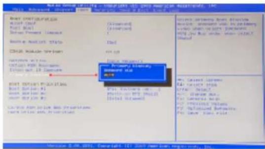
text_image
Next to General Settings - Microsoft Internet Explorer (ASP) 2013 Advanced Options - From New Year's Open-Back Window Help Next Configuration MCC (CNC) First Base Drive Present License New Model Status CHINA Mobile Server Internet Web HTTP: 988 Web Services Device Out: 10 Devices Primary Building Microsoft Web Internet Web Internet Web Services Internet Web Services Internet Web Services Internet Web Services Internet Web Services Internet Web Services Internet Web Services Internet Web Services Internet Web Services Internet Web Services Internet Web Services Internet Web Services Internet Web Services Internet Web Services Internet Web Services Internet Web Services Internet Web Services Internet Web Services Internet Web Services Internet Web Services Internet Web Services Internet Web Services Internet Web Services Internet Web Services Internet Web Services Internet Web Service Internet Web Service Internet Web Service Internet Web Service Internet Web Service Internet Web Service Internet Web Service Internet Web Service Internet Web Service Internet Web Service Internet Web Service Internet Web Service Internet Web Service Internet Web Service Internet Web Service Internet Web Service Internet Web Service Internet Web Service Internet Web Service Internet Web Service Internet Web Service Internet Web Service Internet Web Service Internet Web Service Internet Web Service Internet Web Services Internet Web Services Internet Web Services Internet Web Services Internet Web Services Internet Web Services Internet Web Services Internet Web Services Internet Web Services Internet Web Services Internet Web Services Internet Web Services Internet Web Services Internet Web Services Internet Web Services Internet Web Services Internet Web Services Internet Web Services Internet Web Services Internet Web Services Internet Web Services Internet Web Services Internet Web Services Internet Web Services Internet Web SecurityAdvanced Users
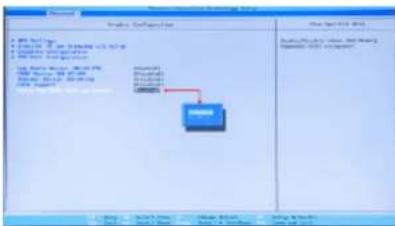
text_image
Logic Software File Edit View Help • 100% Open • 100% Open • 100% Open • 100% Open • 100% Open • 100% Open • 100% Open • 100% Open • 100% Open • 100% Open • 100% Open • 100% Open • 100% Open • 50% • 50% • 50% • 50% • 50% • 50% • 50% • 50% • 50% • 50% • 50% • 50% • 50% • 50% • 50% • 50% • 50% • 50% • 50% • 50% • 50% Open • 50% Open • 50% Open • 50% Open • 50% Open • 50% Open • 50% Open • 50% Open • 50% Open • 50% Open • 50% Open • 50% Open • 50% Open • 50% Open • 50% Open • • 50% • 50% • 50% • 50% • 50% • 50% • 50% • 50% • 50% • 50% • 50% • 50% • 50% • 50% • 50% • 50% • 50% • 50% • 50% • 5 • 5 • 5 • 5 • 5 • 5 • 5 • 5 • 5 • 5 • 5 • 5 • 5 • 5 • 5 • 5 • 5 • 5 • 5 • 5 • 5 • 5 • 5 • 5 • 5 • 5The system will then boot from the graphics card identified first by the PCI Bus.
13.5 Installing Additional ImageDP4 Cards
As the number of required screens increase, the likelihood of reaching a system limitation or encountering problems increases. The system limitations are the amount of address space available and the capacity of the power supply.
13.5.1 Power
The amount of current a power supply can deliver on each voltage rail is limited. Often there is also a limit on the total power.
Each ImageDP4 card requires 0.25A at +3.3V and 1.2A at +12V.
You can calculate the amount of current and the amount of power required for the ImageDP4 cards. For example, the requirements for a 24-screen system of ImageDP4 cards is calculated as follows:
Current
$$ + 3. 3 \mathrm{V} 6 \times 0. 2 5 \mathrm{A} = 1. 5 \mathrm{A} $$
$$ + 1 2 \mathrm{V} 6 \times 1. 2 \mathrm{A} = 7. 2 \mathrm{A} $$
13.6 Installing CODEC Packs to Play Video
DGCPlay utilises the DirectShow codecs installed on the computer to playback a video file. A standard installation of Windows includes codecs for playing WMV files, plus some AVI and MPG files. Many video files require additional 3rd party codec files.
For many of AVI and MPG formats the open source ffdshow package will contain codecs which will allow playback using DGCPlay. ffdshow is available from:
http://ffdshow-tryout.sourceforge.net
MOV files are supported through QuickTime. By default QuickTime is not available through DirectShow. With additional software it is possible to make QuickTime video files available however. There are a number of codecs which do this, for instance:
http://www.codecguide.com/download_kl.htm
http://www.riverpast.com/en/prod/quicktime/
http://www.medialooks.com/products/directshow_filters/quicktime_filter.html
SWF and FLV files are supported by Flash. In the same manner as QuickTime these are not natively supported by DirectShow, although it is possible to use additional software to enable playback. A suitable codec for this might be:
http://www.medialooks.com/products/directshow_filters/flash_source.html
Datapath do not provide any warranty or assurance that these examples will be suitable for commercial use. We simply list them as an example of those available through 3rd parties. Before deployment we advise that any of the above, and any other codec selected, is thoroughly evaluated to confirm their suitability.
13.7 Firmware Updates
The procedures for updating the firmware of your cards can be found in the relevant user guide which is available on your Datapath Recovery Media. Check the Datapath website for the latest version of the user guides.
13.8.2 Reactivate Windows ^®
When the wall controller has been restored the Windows® operating system will need to be re-activated. The software key can be found on the front panel of your wall controller.
13.8.3 Install Display Drivers and Software
Once the Windows® re-activation process is complete the Display Drivers need to be re-installed and if required, the Wall Control application software. The Display Drivers and Wall Control software can be found in the Driver and Tools folder on the recovery media.
For the latest drivers and software go to www.datapath.co.uk
Index
A Disable Onboard Graphics 81
Activate Windows 7 10 Disable the Control Screen 34
ActiveSOX 18 Disclaimer 5
Alarm Configuration 42 Display Drivers 82
B Displaying Video Captures 35
Backplanes 22 Display Setup 11
Bend radii 28 E
BIOS 15 ExCable-G3 19
C ExCable-Optical 19
Cable Handling 32 ExCables-Optical 27
Changing the Order of the Screens 33 Expressg-G3 22
Chassis 20 Express11-G3 22
Class A Declaration of Conformity 50 F
CODEC Packs 83 FAQs 46
Command Line Interface 61 FCC Rules 50
Computer Name: 10 Fonts and Symbols 14
Configure SATA 76 Frame Locking 29
Index
| L | S |
| Language Pack 36 | Safety 16 |
| Lifting Precautions 17 | SBC 15 |
| M | SBC3 22, 54 |
| Maintenance 16 | SBC4 22 |
| Manufacturer Warranty 59 | Screen Order 32 |
| Mechanical Loading 17 | Selecting a Boot Device 83 |
| Multiple ImageDP4 82 | Show Current Status 42 |
| multi-unit rack assembly 17 | SLink-G3 19 |
| N | SLink-Optical 19 |
| Network Security 31 | Summary 18 |
| O | Support Procedures 48 |
| operating system 52, 53, 54 | Symbols 14 |
| Overheating 41 | System Backup 37 |
| Overview 18 | System Buzzer 42 |
| P | System Filter 49 |
| Power Cables 34 | T |
VisionAV-HD 18
VisionAV-SDI 18
VisionDVI-DL 19
VisionRGB-E2s 19
VisionSC-DP2 18
VisionSD4+15 19
VisionSD8 19
VisionSDI2 19
W
Wall Control 12
Wall Control Icons 39
Wall Control-red 39
Wall Control-red Features 38
Wall Control-red-IP 39
Wall Monitor Application 42
Wall Monitor Software 41
Windows®7 Setup 10