AV-2020 - Camera AViPAS - Free user manual and instructions
Find the device manual for free AV-2020 AViPAS in PDF.

User questions about AV-2020 AViPAS
0 question about this device. Answer the ones you know or ask your own.
Ask a new question about this device
Download the instructions for your Camera in PDF format for free! Find your manual AV-2020 - AViPAS and take your electronic device back in hand. On this page are published all the documents necessary for the use of your device. AV-2020 by AViPAS.
USER MANUAL AV-2020 AViPAS
20x HD All-in-one PTZ Camera

natural_image
Line drawing of a portable electronic device with a cylindrical top and base (no text or symbols)User Manual
V1.0
Please read this user manual
thoroughly before using.
Preface
Thank you for using this HD All-in-one PTZ Camera.
This manual introduces the functions, installation process and operation of the IID camera. Prior to installation and usage, please read the manual thoroughly.
Precautions
This product should only be used under the specified conditions in order to avoid any damage to the camera:
■ Do not subject the camera to rain or moisture.
■ Do not remove the cover. Otherwise, you may risk receiving an electric shock. In case of unintended equipment operation, contact an authorized engineer.
■ Never operate under unspecified temperature, humidity or power supply.
■ Please use soft dry cloth to clean the camera. If the camera is very dirty, clean it with diluted neuter detergent: do not use any type of solvents, which may damage the surface.
Note:
This is a class A production. Electromagnetic radiation at certain frequencies may affect the image quality of TV in home environment.
CONTENT
SAFETY GUIDES....1
PACKING LIST 2
QUICK START 2
PRODUCT HIGHLIGHTS....3
CAMERA SPECIFICATIONS....3
CAMERA INTERFACE 5
CAMERA DIMENSION....5
IR REMOTE CONTROLLER....6
VISCA IN (RS232) PORT 9
OSD MENU 10
UVC CONTROL 13
WEB SETTINGS....14
VIEW RTSP STREAM VIA VLC 18
VISCA OVER IP 19
VISCAPROTOCOL....22
PEI CO-D PROTOCOL 29
PELCO-P PROTOCOL....30
WARRANTY....32
SAFETY GUIDES
- Electric Safety Installation and operation must accord with electric safety standard.
- Use caution to transport Avoid stress, vibration or soakage in transport, storage and installation.
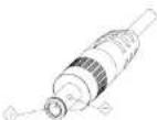
- Polarity of power supply
The power supply of this product is +12V, the max electrical current is 2A. Polarity of the power supply plug is shown in the drawing below:
- Installation precautions
Do not grasp the camera lens when carrying it. Do not touch camera lens by hand. Mechanical damage may result from doing so. Do not use in corrosive liquid, gas or solid environment to avoid any cover (plastic material) damage. Make sure there is no obstacle within rotation range. Do not power on before installation is completed.
- Do not dismantle the camera We are not responsible for any unauthorized modification or dismantling.
CAUTION! Certain frequencies of electromagnetic field may affect the image of the camera!
Note:
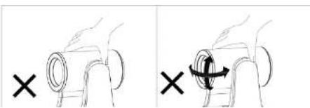
Video quality may be affected by the specific frequencies of electromagnetic field. Never grasp the head of the camera, or move the camera by hand when it is working. Otherwise, mechanism maybe affected.
natural_image
Two hand diagrams showing a circular object being twisted, with one marked by an 'X' and the other by an arrow (no text or symbols present)PACKING LIST
When unpacked, check if all supplied accessories are included:
| Camera | 1pc |
| Power Adapter | 1pc |
| Power Cable | 1pc |
| RS232 Control Cable | 1pc |
| USB2.0 Cable | 1pc |
| Remote Controller | 1pc |
| User Manual | 1pc |
| Double-sided Adhesive | 1pc |
QUICK START
- External interface: RS232 I/O, HDMI output, 3G-SDI output, USB2.0 output, LAN output, DC12V power, Audio input. Please check all connections before powering on the device.

text_image
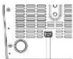
MISA Scale 7500.16 MISA 987 USB Interface HD-321 High deflection Digital interface USB 400 Video Interface 8.0V Interface AC or Environment Line In perforated device AC Adapter AC Bus DC27 Input power switch module- Dial switch settings (at the bottom of the camera):
| Dial Switch (ARM) | |||
| SW-1 | SW-2 | Instruction | |
| 1 | OFF | OFF | Updating mode |
| Dial Switch | |||
| SW-3 | SW-4 | Instruction | |
| 1 | OFF | OFF | reserve |
| 2 | ON | OFF | reserve |
| 3 | OFF | ON | reserve |
| 4 | ON | ON | reserve |
| Dial Switch (USB) | |||
| SW-5 | SW-6 | Instruction | |
| 1 | OFF | OFF | Updating mode |
| 2 | ON | OFF | Working mode |
| 3 | OFF | ON | Undefined |
| 4 | ON | ON | Undefined |
PRODUCT HIGHLIGHTS
- Adopts advanced ISP, 1/2.8-inch 2.1MP sensor, providing full HD video resolution.
■ High-quality 20x optical zoom, 2x digital zoom lens with 60-degree field of view.
IP: HDMI, 3G-SDI, USB video output interface, compatible with different applications.
■ White Balance/ Exposure/ Focus/ Iris can be adjusted automatically or manually.
■ Support PoF+: one single CAT5/6 for video, control and power, highly efficient video encoding.
■ Support line-in function, ACC and LPCM audio encoding.
■ Advanced focusing algorithm: fast and precise focusing performance during movement. - Smooth PTZ mechanism, accurate pan tilt motor control.
■ Up to 128 presets available.
■ Support VISCA, PELCO-P, PELCO-D and VISCA over IP control protocol; IP VISCA over both TCP and UDP.
■ Support RS232 daisy chain, up to 7 cameras under VISCA protocol.
■ Support upside-down (ceiling) installation, H/V flip.
■ Support RS232/UVC control - Standard UVC1.1 protocol, seamlessly compatible with all major video conferencing software and platforms
CAMERA SPECIFICATIONS
HDMI: 1920-1080P60/59.94/50/30/29.97/25/24; 1920+1080160/59.94/50/1280+720P60/59.94/50/30/29.97/25
| RJ45: 1920*10800/1-30 / 1280*7200/1-30 / 1024*576 @1-30 (Main stream) 1280*720@1-30 / 1024*576@1-30 / 650*360 @1-30 (Sub stream) | |
| Video Interface | HDMI.3G-SDI, RJ45, USB2.0 |
| Sensor | 1/2.8" 2.IMP CMOS sensor |
| Zoom | F1.9~98mm, F1.5~3.0 View angle: 60°(Fu)-3.23°(Nca) |
| Rotation Angle | Pan: -170° ~ +170° Tilt: -90° ~ +80° |
| Rotation Speed | Pan: 0°~120% Tilt: 0°~80% |
| Project | remote controller: 10, RS232.128; Accuracy: 0.1° |
| Control Port | RS232, RJ45 (VISCA over IP), USB2.0(UNC1.1) |
| Network Speed | 1000M |
| Video encode | H.264VH.265 (default H.265) |
| Bit Rate Control | Variable Bit Rate, Constant Bit Rate |
| Video Bit Rate | 0Kbps~15360Kbps |
| IP Protocol | TCMP, HTTP, RTSP, RTMP, DHCP, Oncif |
| PbE+ | Support |
| Daisy Chain | RS232 serial daisy chain (up to 7 units under VISCA protocol) |
| Minimum Lax | 0.1 Lux (F1.5) |
| White Balance | Auto/Induce/Outdoor/Manual/AWT/PUSH |
| Exposure | Auto/Manual/Bridge/Shutter/Iris |
| Focus | Auto/Manual |
| Iris | Auto/Manual |
| Electric Stainer | Auto/Manual |
| Gamma | Support |
| WDR | Support |
| BLC | Support |
| 2D/3D Noise Reduction | Support |
| Anti-Plicker | OFF/50Hz/60Hz |
| H/V Flip | Support |
| Input Voltage | DC13V/ Polb+ |
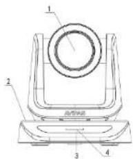
CAMERA INTERFACE
text_image
1 2 3 4- Camera Lens
- Camera Base
- IR Receiver Panel
- Power Indicator Light
- Diet Switch

6. Triped Screw Hole
7. Installation Hole
8. RS232 Control Input
9. RS232 Control Output
10. HDMI Output

1.3G-SDI Output
12. USR Output
13, RJ45 Output
14. DC12V Power Jack
15. Lane-in Audio Input
CAMERA DIMENSION(MM)
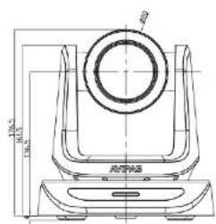
text_image
100% 80% 100%
natural_image
Technical line drawing of a mechanical component with a central flange and base (no text or symbols)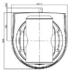
text_image
16.75 2.0 16.8 2.0
text_image
1.4" 200V Focal Motor 35.24pA 35.24pAIR REMOTE CONTROLLER
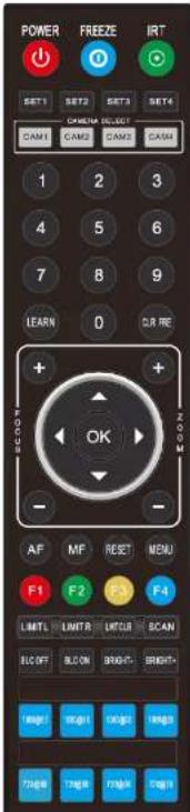
text_image
POWER FREEZE IRT SET1 SET2 SET3 SET4 CHINA SELECT CAM1 CAM2 CAM3 CAM 1 2 3 4 5 6 7 8 9 LEARN 0 DR RE + - OK ZOOM AF MF RESET MENU F1 F2 F4 LIMITL LIMITR LIMITR SCAN ELO OFF ELO ON BRIGHT BRIGHT RGB OK OK RGB TANG TANG TANG
POWER
Under normal working mode, press POWER to enter standby mode;
Press it again, the camera will start self-configuration, then go back to HOME position.
It will go to preset position 0 if the preset is set.
FREEZE (do NOT support USB output)
Press FREEZE to freeze/unfreeze the image.
IRT (IR Transfer/IR Pass)
Open / close the IR pass function. Once press the IRT key, the camera will receive and pass the IR remote control signal to the codec/terminal (via VISCA IN port).
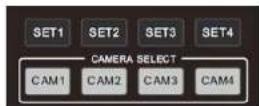
SET 1-SET4 ADDRESS SETTING
To set the current camera's address (ID), press and hold the key for 3 seconds until the backlight of that key is ON.
CAMI-CAM4 (CAMERA SELECTING)
Press the corresponding camera number to select the camera.

NUMERIC KEY (1-9)
Set preset: press and hold the number for 3 seconds to set preset position.

FOCUS
Manually adjust focus, only valid under manual mode.
ZOOM
Manually adjust zoom.
Under camera normal mode, use navigate keys to par/tilt:
After entering camera OSD, use navigate keys to select and enter submenu.
OK/HOME KEY
Under camera normal mode, press OK to make the camera go back to
its HOME position;
After entering camera OSD, press OK to confirm selection.

AF: Auto focus
MF: Manual focus
RESET: Press and hold for 3 seconds to reset camera
MENU: Enter OSD menu
LEARN+LIMIT L: Set the pan tilt left limit position.
LEARN+LIMIT R: Set the pan tilt right limit position.
LEARN+LMT CLR: Clear all limit position.
BLC OFF/BLC ON: Not available
BRIGHT-/BRIGHT+: Set image brightness, only valid under bright
priority exposure mode.

Video Format Selection:
Press and hold for 3 seconds to select different video format output.
VISCA IN (RS232 PORT)
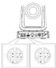
text_image
Diagram of a device with labeled ports and two circular component layouts below, likely illustrating a system or control interface.| No. | V_IN | V_OUT |
| 1 | DTR | DTR |
| 2 | DSR | DSR |
| 3 | TXD | TXD |
| 4 | GND | GND |
| 5 | RXD | RXD |
| 6 | A | |
| 7 | IROUT | |
| 8 | B |
| VISCA IN | RS485 |
| 1 | |
| 2 | |
| 3 | |
| 4 | |
| 5 | |
| 6 | A(+) |
| 7 | IR OUT |
| 8 | B(-) |
VISCA IN & DB9 Connection
| Camera VISCA IN | Windows DB-9 | ||
| 1 | DTR | 6 | DSR |
| 2 | DSR | 4 | DTR |
| 3 | TXD | 2 | RXD |
| 4 | GND | 5 | GND |
| 5 | RXD | 3 | TXD |
| 6 | A (+) | ||
| 7 | IR OUT | ||
| 8 | B (-) | ||
VISCA IN &Mini DIN Connection
| Camera VISCA IN | Mini DIN | ||
| 1 | DTR | 1 | DSR |
| 2 | DSR | 2 | DTR |
| 3 | TXD | 5 | RXD |
| 4 | GND | 4 | GND |
| 5 | RXD | 3 | TXD |
| 6 | A(+) | 6 | NC |
| 7 | IR OUT | 7 | NC |
| 8 | B(-) | 8 | NC |
VISCA Network Construction:
SERIAL PORT CONFIGURATION
Parameter Valma Parameter Valna
OSD MENU
- Under working mode, press the MENU key on the IR remote controller, to enter the OSD menu as shown below:

-
After entering the main menu, use navigate UP/DOWN keys to select the from the main menu options.
-
Press RIGHT key to enter sub menu; use UP/DONW key to select the sub menu; use LEFT/RIGHT key to change current settings.
-
Press MENU key again to return to the previous menu, repeat and exit the OSD menu.
-
OSD Menu setting list
| SYSTFM | PROTOCOL | Optional item: VISCA/ PFI.CO-P/ PFI.CO-D | Defaults: VISCA |
| ADDRESS | VISCA: 1~7 PFI.CO-P/D: 1~255 | Defaults: 1 | |
| BAUD RATE | 2400/4800/9600/115200 | Defaults: 9900 | |
| PIL LOCK | Protocol lock: once set, above protocol settings will be locked | Defaults: OFF | |
| RS485 | RS485 ON/OFF | Defaults: ON | |
| VISCA | OVER ALL/ OVER IP/ OVER COM | Defaults: OVERALL | |
| LANGUAGE | Chinese/ English | Defaults: English |
| EXPOSURE MODE | AUTO MANUAL/ SHUTTER/ IRIS/ BRIGHT | Default: AUTO |
| SHUTTER | Shutter speed: 150-171000, only valid under MANUAL and SHUTTER mode | Default: AUTO |
| IRIS | Iris setting: CLOSE-F1.8, only valid under MANUAL and IRIS mode | Default: AUTO |
| WD MODE | ON/OFF | Default: OFF | |
| WD LEVEL | WDR Level | Default: 1 | |
| BLC | ON/OFF | Default: OFF |
| IMAGIP | WB MODE | ATW/ MANUAL/ AUTO/ INDOOR/ OUTDOOR/ PUSI | Default: ATW |
| R GAIN | Red gain level: 0-255, only valid under manual white balance mode. | Default: AUTO | |
| B GAIN | Blue gain level:0-255, only valid under manual white balance mode | Default: AUTO | |
| TICK | Anti-Flicker setting: 50%HZ | Default: 50HZ | |
| DZOOM | ON/OFF | Default: OFF | |
| FOCUS | Select focus mode | Default: AUTO |
| QUALITY | 2D NR | 2D noise reduction: the bigger value, the less noise on image, the lower the resolution | Default: OFF |
| 3D NR | 3D noise reduction: OTP/AUTO0-4, the bigger value, the less motion noise on image, high value will cause image smear. | Default: AUTO | |
| SHARPNESS | Sharpness setting: 0~15 | Default: 3 | |
| CONTRAST | Set constraint level | Default: 8 | |
| SATURATION | Set saturation level | Default: 8 | |
| GAMMA | Select gamma level | Default: 0 | |
| AF | LOW/NORMAL/ HIGH | Default: | |
| SENSITIVITY | NORMAL. |
| SPEEDBYZ | SpeedByZoom: proportional speed, the bigger zoom, the slowerspeed | Default: ON | |
| FLIP.HOR | Flip horizontal | Default: OFF | |
| MENU MIR | NORMAL/ MIRROR | Default: NORMAL. |
| FORMAT | 1080P59.94 | After selecting the system, press OK to confirm. If it is the currently selected system, it will not be activated. |
| 1080P50 | ||
| 1080E59.94 | ||
| 1080I50 | ||
| 1080P39.97 | ||
| 1080P25 | ||
| 720P59.91 | ||
| 720P50 | ||
| 720P29.97 | ||
| 720P25 | ||
| 1080P60 | ||
| 1080P30 | ||
| 720P60 | ||
| 720P30 | ||
| 1080P60 | ||
| 1080P24 |
| IP | DHCP | ON/OFF | Use up/down/left/right navigation keys to select item to set, and use numeric keys to enter parameters. Press menu button to return. |
| IP | 192.168.001.188 | ||
| MASK | 255.255.255.000 | ||
| GW (Gateway) | 192.168.001.001 | ||
| MAIN | Default: 1920*1080 | ||
| BITRATE | Default: 04096k | ||
| SUB | Default: 1280*720 | ||
| BITRATE | Default: 02648k |
| ALL RESET | Reset all settings to default |
| INFO | IR ADDR | Camera IR control address |
| USB | USB firmware version | |
| CLIENT | Default client end protocol VISCA | |
| MODEL NO. | Model number | |
| ARM VER | ARM firmware version | |
| PPGA VER | PPGA firmware version | |
| CAM VER | Camera version | |
| RELEASE | Software release date |
SET IP ADDRESS IN MENU
In order to facilitate customer debugging, the camera supports IP address configuration under OSD.
- Press "MENU" to enter the camera OSD, then select "IP";
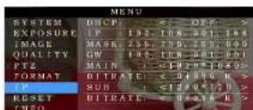
- Press “▶” navigation key to enter the IP setting interface. Select the parameter needs to be changed using the navigation “▲” and “▼” keys;
- Use numeric keys to set the corresponding parameters. After finishing entering, press the "MEN." again to complete and save the setting;
- Press "MENU" again to exit menu.
UVC CONTROL
- The interval of control commands sending from the server (via USB) to the camera should be no less than 250ms.
| PU_BRIGHTNESS_CONTROL | 1 01 01 4d 00 00 0p 6q FF |
| PU_CONTRAST_CONTROL | 1 01 04 A2 00 00 0p 6q FF |
| PU_SATURATION_CONTROL | 1 01 04 A1 00 00 0p 6q TT |
| PU_SHARINESS_CONTROL | x 01 01 42 00 00 0p 6q FF |
| PU_GAMMA_CONTROL | 8x 01 04 58 0p FF |
| PU_WHITE_BALANCE_TEMPERATURE_CONTROL | 8x 01 04 35 0X TT |
| PU_BACKLIGHT_COMPENSATION_CONTROL | $1 01 01 33 02/03 FF |
| PU_POWER_LINE_FREQUENCY_CONTROL | 8x 01 01 AA 000102 FF |
| CT_ZOOM_ABSOLUTE_CONTROL | 8x 01 04 47 bp dq fr fr FF |
| CT_PANTILT_ABSOLUTE_CONTROL | 8x 01 06 02 VV WW 0Y 0Y 0Y 0Z 0Z 0Z T |
| CT_PANTILT_RELATIVE_CONTROL | 8x 01 06 01 pp qq r as FF |
| CT_ZOOM_RELATIVE_CONTROL | 8x 01 04 07 pp FF |
WEB SETTINGS
1. Download and install Flash Player
When access the camera via Internet Explorer browser for the first time, Flash Player needs to be installed.
We recommend users download it from flash official website to get latest version:
https://www.flash.cn/english
After installation is complete, it will be listed in PC's Programs and Features Control Panel:
2. Login
To access the camera interface, open IE browser, input IP address (default IP address is 192.168.1.188). Users can select language (Chinese/English). Default username: admin Default password: admin

3. Real-time Preview
When low in to the web interface for the first time, a messcise below will show. Please go to II: browser

natural_image
Decorative white bicycle placed in a wicker basket with colorful flowers, displayed on a red table (no text or symbols visible)On the Preview interface shown above, there is a virtual control panel on the right-hand side. Options include pan, tilt, zoom, focus, presets, focus speed and zoom speed. On the bottom of image preview, main stream and sub stream preview can be selected.
4. Configuration
Click "Setting" to enter camera configuration interface shown below:

text_image
Video Records Source Target Source ID Volume Target Volume Label Volume Label Volume Label Volume Label Volume Label Volume Label Volume Label Volume Label Volume Label Volume Label Volume Label Volume Label Volume Label Volume Label Volume Label Volume Label Volume Label Volume Label Volume Label Volume Label Volume Label Volume Label Volume Label Volume Label Volume Label Volume Label Volume Label Volume Label Volume Label Volume Label Volume Label Volume Label Volume Label Volume LabelVideo Encode: To set image encoding mode, main stream and sub stream resolution/bit rate/frame rate, bit rate control option, I frame interval, etc. as shown above.
Video Encode
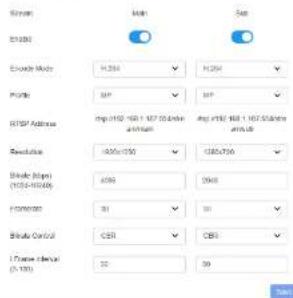
text_image
Screen Make Set EN200 Exchange Mode: H:354 H:254 Profile: HP HP USB Address: mp:1192 160 1.167 50.000x avg:1192 160 1.167 50.000x Revolve: 100x150 150x70 Blade (Top): (105-1050) 400 500 FormName: 31 31 Blade Control: CER CER Trend Date: (1-10) 32 39Video Transmission: To set RTMP settings.

Audio Setting: To enable/disable embedded audio. Audio encoding mode can be selected. Parameters such as sampling rate and bit rate can be adjusted.
Audio Setting

Image Parameter: To set focus, exposure, white balance, image, image quality, noise-reduction, etc.
| Image Adjust

Focal Express White Science Image Image Quality Water Education


Issue Expression: M&V Nalore, mgp. mgy Gally, M&V Nalore


text_image
File Edit View Import Window Image Tools Help Name Image Photo Image Quality New Version Video Photo Image Image Image Image Image Image Image Image Image Image Image Image Image Image Image Image Image Image Image Image Image Image Image Image Image Image Image Image Image Image Image Image Image Image Image Image Image Image Image Image Image Image Image Image Image Image Image Image Image Image
Ethernet: To set DHCP mode, IP address, subnet mask, default gateway, http port, web port, main stream port and sub stream port. Default settings are as following:
| DHCP | OFF | Default gateway | 192.168.1.1 |
| IP address | 192.168.1.188 | HTTP port | 80 |
| Subnet mask | 255.255.255.0 | RTSP port | 554 |
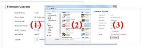
Firmware upgrade: To update the camera ISP. Steps are shown below:
Click "clicking to upload file", in the dialog box, select the upgrade file. Click "upgrade" to start the modeling process.
text_image
Firmware Upgrade Created Vehicle 13.0.1 Device Name: 45 Conformers Serial Number: 1000000000 Exclude Version 26.0.0 System Work: V1.0.0 App Version: WebCD Upgrade Select (1) (2) (3)Reset to default: To reset the camera to default settings.
Reset simply: reset camera image settings; Reset completely: reset all camera settings including IP configurations, image settings, language and protocol; Reboot: reboot ISP part of the camera.
Account Setting: To set camera account username and password.


USING VLC TO VIEW RTSP/RTMP VIDEO
Default RTSP main streaming URL: rtsp://192.168.1.188/stream/main
Default RTSP sub streaming URL: rtsp://192.168.1.188/stream/sub
Default RTMP main streaming URL: rimp://192.168.1.188:1935/app/rimpstream0
Default RTMP sub streaming URL: rtmp://192.168.1.188:1935/app/rtmpstream
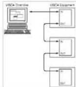
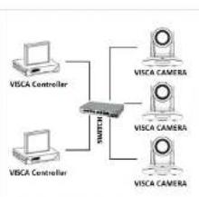
VISCA OVER IP
VISCA over IP means VISCA protocol transmit via IP.
This can be used to reduce RS232/RS485 cable layout
(the controller must support IP communication function).
Communication port spces:
● Control port: RJ45 Gigabit LAN
• IP protocol: IPv4
● Transmit protocol: UDP
- IP address: set via web interface or OSD menu
- Port address: 52381
- Confirm send/transmission control: depend on applied program
● Applied range: in the same segment, not suitable for bridge network.
● To apply, enter camera OSD, choose VISCA option: OVER IP
How to use VISCA over IP
flowchart
graph TD
    A["VISCA Controller"] --> C["Switch"]
    B["VISCA Controller"] --> C
    D["VISCA CAMERA"] --> C
    E["VISCA CAMERA"] --> C
    F["VISCA CAMERA"] --> C
VISCA Command
Commands are sent from controller to peripheral equipment (camera), and when peripheral equipment receives commands, it returns ACK. When the command is executed, a complete message will be returned.
VISCA Inquiry
Inquiry is sent from controller to peripheral equipment (camera), and when peripheral equipment receives the command, it will return required message.
VISCA Reply
It is sent from peripheral equipment (camera) to controller. ACK, which is the complete message, can be either reply or error reply.
Command format: Note that LAN output is big-endian, and LSB is in the front.

Payload type: data definitions are listed below.
| Name | Value (Byte 0) | Value (Byte 0) | Value (Byte 0) |
| VISCA command | 0x01 | 0x00 | Stores the VISCA command. |
| VISCA inquiry | 0x01 | 0x10 | Stores the VISCA inquiry. |
| VISCA reply | 0x01 | 0x11 | Stores the reply for the VISCA command and VISCA inquiry, or VISCA device setting command. |
| VISCA device setting command | 0x01 | 0x20 | Stores the VISCA device setting command. |
| Control command | 0x02 | 0x00 | Stores the control command. |
| Control reply | 0x02 | 0x01 | Stores the reply for the control command. |
Payload length: Valid data length in Payload (1\~16), is the command length.
For example, when valid data length is 16-byte. Byte 2: 0x00; Byte 3: 0x10
Controller will save sequence number of each command, when one command sent, the sequence number of the command will add 1; when the sequence number reaches the max, it will return back to 0. The peripheral equipment will save sequence number of each command, and return the sequence number to controller.
Payload: According to Payload type, the following data will be saved.
• VISCA command: Save VISCA command packet
● VISCA inquiry: Save VISCA message packet
- VISCA reply: Save VISCA return packet
- VISCA device setting command. Save VISCA equipment setting command packet.
● Control command: The following data is saved in control command payload
| Name | Value | Description |
| RESET | 0x01 | Resets the sequence number to 0. The value that was set as the sequence number is |
- Controlled reply: The following data is saved in return command payload of control command.
| Message | Value | Description |
| ACK | 0x11 | Reply for RESET |
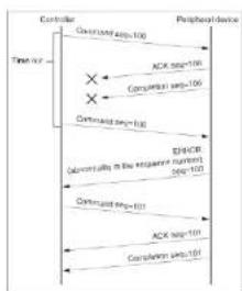
Delivery confirmation:
VISCA over IP uses UDP as transmission communication protocol. UDP communication message transmission is not stable, it is necessary to confirm delivery and resent in application.
Generally, when controller sends a command to peripheral equipment, controller will wait for the return message then send the next command, we can detect and confirm if the peripheral equipment receive the commands from its return message's lag time. If controller detects it overtime, it is regarded as error transmission. Controller will resend the commands to check peripheral's status. The resent command sequence number is same as the last one. Following chart lists possible received message and the corresponding status after the resent command.
| Lost message | Received message for retransmission | Status after retransmission | Correspondence after retransmission |
| Command | ACK message | Command is performed by retransmission. | Continue processing. |
| ACK message | ERROR (Abnormality in the sequence number.) | Command has been performed.If only the ACK message is lost, the completion message returns. | If the result by the completion message is needed, retransmit by updating the sequence number. |
| Completion message for the command | ERROR (Abnormality in the sequence number.) | Command has been performed. | If the result by the completion message is needed, retransmit by updating the sequence number. |
| Inquiry | Reply message | Inquiry is performed by retransmission. | Continue processing. |
| Reply message for the inquiry | ERROR (Abnormality in the sequence number.) | Inquiry has been performed. | If the result by the reply message is needed, retransmit by updating the sequence number. |
| Error message | First message | Command is not performed.If the error cause eliminates, normal reply is returns (ACK, reply messages). | Eliminate the error cause. If neutral reply returns, continue processing. |
| Inquiry of the VISCA device setting command | Reply message of the VISCA device setting command | Inquiry has been performed by retransmission. | Continue processing. |
| Reply message of the VISCA device setting command | ERROR (Abnormality in the sequence number.) | Inquiry has been performed. | If the result by the reply message is needed, retransmit by updating the sequence number. |

flowchart
graph TD
    A["Consumer"] --> B["Command seg=100"]
    B --> C["Peripheral device"]
    D["Time out"] --> E["Command seg=100"]
    E --> F["ACK seq=100"]
    F --> G["Completion seg=100"]
Sequence chart when command last
flowchart
graph TD
    A["Controller"] --> B["Time Time"]
    B --> C["Control"]
    C --> D["Peripherals"]
    D --> E["ACK Data transmission"]
    E --> F["Comparison"]
    F --> G["OR Gate"]
    G --> H["Comparison"]
    H --> I["ACK Data transmission"]
    I --> J["Comparison"]
    J --> K["ACK Data transmission"]
    K --> L["Comparison"]
    L --> M["ACK Data transmission"]
    M --> N["Comparison"]
    N --> O["ACK Data transmission"]
    O --> P["Comparison"]
    P --> Q["ACK Data transmission"]
    Q --> R["Comparison"]
    R --> S["ACK Data transmission"]
    S --> T["Comparison"]
    T --> U["ACK Data transmission"]
    U --> V["Comparison"]
    V --> W["ACK Data transmission"]
    W --> X["Comparison"]
    X --> Y["ACK Data transmission"]
    Y --> Z["Comparison"]
    Z --> AA["ACK Data transmission"]
    AA --> AB["Comparison"]
    AB --> AC["ACK Data transmission"]
    AC --> AD["Comparison"]
    AD --> AE["ACK Data transmission"]
    AE --> AF["Comparison"]
    AF --> AG["ACK Data transmission"]
    AG --> AH["Comparison"]
    AH --> AI["ACK Data transmission"]
    AI --> AJ["Comparison"]
    AJ --> AK["ACK Data transmission"]
    AK --> AL["Comparison"]
    AL --> AM["ACK Data transmission"]
    AM --> AN["Comparison"]
    AN --> AO["ACK Data transmission"]
    AO --> AP["Comparison"]
    AP --> AQ["ACK Data transmission"]
    AQ --> AR["Comparison"]
    AR --> AS["ACK Data transmission"]
    AS --> AT["Comparison"]
    AT --> AU["ACK Data transmission"]
    AU --> AV["Comparison"]
    AV --> AW["ACK Data transmission"]
    AW --> AX["Comparison"]
    AX --> AY["ACK Data transmission"]
    AY --> AZ["Comparison"]
    AZ --> BA["ACK Data transmission"]
    BA --> BB["Comparison"]
    BB --> BC["ACK Data transmission"]
    BC --> BD["Comparison"]
    BD --> BE["ACK Data transmission"]
    BE --> BF["Comparison"]
    BF --> BG["ACK Data transmission"]
    BG --> BH["Comparison"]
    BH --> BI["ACK Data transmission"]
    BI --> BJ["Comparison"]
    BJ --> BK["ACK Data transmission"]
    BK --> BL["Comparison"]
    BL --> BM["ACK Data transmission"]
    BM --> BN["Comparison"]
    BN --> BO["ACK Data transmission"]
    BO --> BP["Comparison"]
    BP --> BQ["ACK Data transmission"]
    BQ --> BR["Comparison"]
    BR --> BS["ACK Data transmission"]
    BS --> BT["Comparison"]
    BT --> BU["ACK Data transmission"]
    BU --> BV["Comparison"]
    BV --> BW["ACK Data transmission"]
    BW --> BX["Comparison"]
    BX --> BY["ACK Data transmission"]
    BY --> BZ["Comparison"]
    BZ --> CA["ACK Data transmission"]
    CA --> CB["Comparison"]
    CB --> CC["ACK Data transmission"]
    CC --> CD["Comparison"]
    CD --> CE["ACK Data transmission"]
    CE --> CF["Comparison"]
    CF --> CG["ACK Data transmission"]
    CG --> CH["Comparison"]
    CH --> CI["ACK Data transmission"]
    CI --> CJ["Comparison"]
    CJ --> CK["ACK Data transmission"]
    CK --> CR["Comparison"]
    CR --> CS["ACK Data transmission"]
    CS --> CT["Comparison"]
    CT --> CU["ACK Data transmission"]
    CU --> CV["Comparison"]
    CV --> CW["ACK Data transmission"]
    CW --> CX["Comparison"]
    CX --> CY["ACK Data transmission"]
    CY --> CZ["Comparison"]
    CZ --> DA["ACK Data transmission"]
    DA --> DB["Comparison"]
    DB --> DC["ACK Data transmission"]
    DC --> DD["Comparison"]
    DD --> DE["ACK Data transmission"]
    DE --> DF["Comparison"]
    DF --> DG["ACK Data transmission"]
    DG --> DH["Comparison"]
    DH --> DI["ACK Data transmission"]
    DI --> DJ["Comparison"]
    DJ --> DK["ACK Data transmission"]
    DK --> DL["Comparison"]
    DL --> DJ
Sequence chart when returned message lost
Note: Do not change IP address, subnet mask, or gateway parameters under VISCA over IP mode, otherwise, it will cause network inconsistency.
VISCA PROTOCOL.
Part 1 Camera Return Commands
| Ack/Completion Message | ||
| Command Packet | Note | |
| ACK | 0.41 FF | Returned when the command is accepted. |
| Completion | 0.51 FF | Returned when the command has been executed. |
z = camera address + 8
| Error Messages | ||
| Command Packet | Note | |
| Syntax Error | All 60 02 IT | Returned when the command format is different or when a command with illegal command parameters is accepted |
| Command Not Executable | All 61 41 IT | Returned when a command cannot be executed due to current conditions. For example, when commands controlling the focus manually are received during auto focus. |
| Command type | function | command | |
| IF Clear | Broadcast | 88 01 00 01 FF | IF Clear |
| CommandCancel | 8x 21 FF | ||
| CAM_Power | On | 8x 01 04 00 02 FF | Power ON/OFF |
| Off | 8x 01 04 00 03 TF | ||
| CAM_Zoom | Stop | 8x 01 04 07 10 FF | |
| Tole (Standard) | 8x 01 04 07 02 FF | ||
| Wide (Standard) | 8x 01 04 07 03 TF | ||
| Tole (Variable) | 8x 01 04 07 2p FF | p = 0(low)~7(high) | |
| Wide (Variable) | 8x 01 04 07 3p FF | ||
| Direct | 8x 01 04 47 0p 0q 0r 0s FF | pages: Zoom Position f(6wide) -0x4DIM(cale) | |
| Direct with speed | 8x 0A 04 47 0t 0p 0q 0r 0s FF | t spd 0~7pages: Zoom Position f(6wide) -0x4DIM(cale) | |
| CAM_DZoom | ON | 8x 01 04 06 02 FF | |
| Off | 8x 01 04 06 03 TF | ||
| Combine Mode | 81 01 04 36 10 FF | Combine with optical zoom control | |
| Separate Mode | 81 01 04 36 01 FF | Separate with optical zoom control | |
| Stop | 81 01 04 06 00 FF | Enable In separate mode | |
| Tole (Variable) | 81 01 04 06 2p FF | Enable In separate mode | |
| Wide (Variable) | 81 01 04 06 3p FF | Enable In separate mode | |
| Direct | 81 01 04 46 0p 0q 0r 0s FF | Enable In separate mode | |
| CAM_Focus | Stop | 8x 01 04 08 00 FF | |
| Tar (Standard) | 8x 01 04 08 02 TF | ||
| Near (Standard) | 8x 01 04 08 03 FF | ||
| Tar (Variable) | 81 01 04 08 2p FF | p=0 (Low) to 7 (High) | |
| Near (Variable) | 81 01 04 08 3p FF | p=0 (Low) to 7 (High) | |
| Direct | 8x 01 04 48 0p 0q 0r 0s FF | pages: Focus Position | |
| Auto Focus | 81 01 04 28 02 FF | ||
| Manual Focus | 81 01 04 38 03 FF | ||
| One Push AF | 8x 01 04 18 01 FF | ||
| 8x 01 04 47 0p 0q 0r 0s FF | pages: Zoom Position |
w 11 and A7 has no d is
pqrs: Zoom Position
| Command type | function | command | |
| OnePush | 8x 01 04 25 02 FF | ||
| ATW | 8x 01 04 25 04 FF | ||
| Manual | 8x 01 04 25 05 FF | ||
| Sodium lamp | 8x 01 04 25 08 FF | ||
| Illumescend | 8x 01 04 25 09 TF | ||
| OnePush Trigger | 8x 01 04 10 05 TF | ||
| CAM_RGain | Reset | 8x 01 04 05 00 FF | Manual Control of R Gain |
| Up | 8x 01 04 05 02 FF | ||
| Down | 8x 01 04 05 03 FF | ||
| Direct | 8x 01 04 15 00 00 0p 0q FF | pq: R Gain (0-0xFF) | |
| CAM Bigain | Reset | 8x 01 04 04 00 FF | Manual Control of R Gain |
| Up | 8x 01 04 04 02 FF | ||
| Down | 8x 01 04 04 02 FF | ||
| Direct | 8x 01 04 14 00 00 0p 0q TF | pq: B Gain (0-0xFF) | |
| CAM_AE | Full Auto | 81 01 04 29 00 FF | Automatic Exposure mode |
| Manual | 81 01 04 39 03 FF | Manual Control mode | |
| Shutter Priority | 81 01 04 29 0A TF | Shutter PriorityAutomatic Exposure mode | |
| Iris Priority | 81 01 04 39 08 FF | Iris Priority AutomaticExposure mode | |
| Bright | 81 01 04 39 00 FF | Bright Mode (Manual control) | |
| CAM_Shutter | Reset | 8x 01 04 0A 00 TF | Shutter Setting |
| Up | 8x 01 04 0A 02 FF | ||
| Down | 8x 01 04 0A 02 FF | ||
| Direct | 8x 01 04 4A 00 00 0p 0q FF | pq: Shutter Position (0-0x15) | |
| CAM_Iris | Reset | 8x 01 04 0B 00 FF | Iris Setting(0-0xD) |
| Up | 8x 01 04 0B 02 FF | ||
| Down | 8x 01 04 0B 03 FF | ||
| Direct | 8x 01 04 4B 00 00 0p 0q FF | pq: Iris Position (0-0x15) | |
| Reset | 8x 01 04 0C 00 FF | ||
| Up | 8x 01 04 0D 02 FF | ||
| Down | 8x 01 04 0D 03 FF | ||
| Direct | 8x 01 04 4D 00 00 0p 0q FF | pg: Bright ( Position (0-0x18) | |
| CAM_OverallBright | Direct | 8x 01 04 A4 00 00 0p 0q FF | pg: Bright ( Position (0-0x0F) different with AT-BRIGHT |
| CAM_WDR | On | 8x 01 04 2D 02 FF | Exposure Compensation ON/OFF |
| Off | 8x 01 04 2D 02 TF | ||
| Direct | 8x 01 04 D3 pg FF | pg: ExpComp Position (0-0x6) | |
| CAM_BackLight(BL C) | On | 8x 01 04 33 02 FF | BackLight On |
| Off | 8x 01 04 33 03 FF | BackLight Off | |
| CAM Sharmpress | Reset | 8x 01 04 02 00 TT | Aperture Control |
| Up | 8x 01 04 D2 02 FF | ||
| Down | 8x 01 04 02 03 FF | ||
| Direct | 8x 01 04 42 00 00 0p 0q FF | pg: Aperture Gain (0-0x0F) | |
| CAM_Memory(preset 1) | Reset | 8x 01 04 3F 00 0p FF | pg: Preset Number (-0 to 127) Corresponds to 0 to 9 on the Remote Commander |
| Set | 8x 01 04 2F 01 0p FF | ||
| Recall | 8x 01 04 2F 02 0p FF | ||
| CAM_LR_Reverse | On | 8x 01 04 61 02 FF | Image Flip Horizontal ON/OFF |
| Off | 8x 01 04 61 03 FF | ||
| CAM_PictureFlip | On | 8x 01 04 66 02 TT | Image Flip Vertical ON/OFF |
| Off | 8x 01 04 66 03 FF | ||
| CAM_RS48SCI | On | 8x 01 06 A5 02 FF | |
| Off | 8x 01 06 A5 03 TT | ||
| CAM_Saturation | Saturation | 8x 01 04 A3 00 00 0p 0q FF | Pg: saturation level 0x00-0x6 |
| CAM_Concast | Contrast | 8x 01 04 A2 00 00 0p 0q FF | Pg: Contrast level 0x01-0xff |
| CAM_SpeedByZoom | On | 8x 01 06 A0 02 FF | |
| Off | 8x 01 06 A0 03 TF | ||
| CAM_PTSpeed | PT Speed | 8x 01 04 C1 00 00 0p 0q FF | Pg: PT speed 0x05-0x18 |
| CAM_ZoomSpeed | Zoom Speed | 8x 01 04 D1 00 00 0p 0q FF | Pg: Zoom speed 0x01-0x07 |
| Down | 8x 01 04 A4 02 FF | Mount Down | |
| CAM_ColoGain | Direct | 8x 01 04 49 00 00 00 0p FF | ( 0 - 00DF) |
| CAM 2D Noise Reduction | Direct | 8x 01 04 53 0p FF | 0 – OFF1 – ON |
| CAM_3D Noise Reduction | Direct | 8x 01 04 54 0p FF | 0 – OFF1 – AUTO2-5 – level |
| FLUCK | 50HZ | 81 01 04 23 01 FF | |
| 60HZ | 81 01 04 23 02 FF | ||
| OFF | 81 01 04 23 00 FF | ||
| VideoSystem Set | 8x 01 06 25 00 pp FF | pp: Video format1080P60 0x2F1080P50 0x2F1080P60 0x011080P50 0x041080P50 0x061080P25 0x08720P60 0x09720P50 0x0C720P50 0x0F720P25 0x11 | |
| CAM_IDWrite | 8x 01 04 22 0p 0q 0r 0s FF | pq: Camera ID (=0000 to FFFF) | |
| IP address control | IP set | 8x 01 04 AB 0p 0q 0r 0s 0m 0n0x 0y FF | Set ip to pq:rs:mm.xy |
| Mask set | 8x 01 04 AC 0p 0q 0r 0s 0m 0n0x 0y FF | Set mask to pq:rs:mm.xy | |
| Gateway set | 8x 01 04 AD 0p 0q 0r 0s 0m0x 0x 0y FF | Set gateway in : pq:rs:mm.xy | |
| SYS_Menu | Menu On | 8x 01 06 06 02 FF | Turn on the menu |
| Menu Off | 8x 01 06 06 02 FF | Turn off the menu | |
| Menu Back | 8x 01 06 06 10 FF | Menu stop back | |
| Menu Ok | 8x 01 7F 01 02 00 01 FF | Menu ok | |
| IR_Receive | On | 8x 01 06 06 02 FF | IR(remote commander) receive ON/OFF |
| Off | 8x 01 06 06 02 FF | ||
| On/Off | 8x 01 06 06 10 FF | ||
| Up | 8x 01 06 01 VV WW 03 01 FF | VV: Pan speed 0x01 (low speed) | |
| Down | 8x 01 06 01 VV WW 03 02 FF | ||
| DownLeft | 8x 01 06 01 VV WW 01 02 FF | ||
| DownRight | 8x 01 05 01 VV WW 02 02 FF | ||
| Stop | 8x 01 05 01 VV WW 03 05 FF | ||
| AbsolutePosition | 8x 01 05 02 VV WW0Y 0Y 0Y 0Y 0Z 0Z 0Z FF | ||
| RelativePosition | 8x 01 06 03 VV WW0Y 0Y 0Y 0Y 0Z 0Z 0Z FF | ||
| Reset | 8x 01 06 04 FF | ||
| Reset | 8x 01 06 05 FT | ||
| Pan-Att limitSet | Set | 8x 01 05 07 00 0W0Y 0Y 0Y 0Y 0Z 0Z 0Z FF | W:1 UpRight 0:DownLeftYYYY: Pan LimitPosition(TBD)ZZZZ: Tilt LimitPosition(TBD) |
| Clear | 8x 01 05 0G 01 0W07 0F 0F 0F 0C 0F 0F 0F FF |
Part 2 Camera Control Command
| Command type | command | return | note |
| CAM PowerLiq | 8x 09 04 00 FF | y0 50 02 FF | On |
| y0 50 03 FF | Off Standby | ||
| CAM_ZoostPosLiq | 8x 09 04 47 FF | y0 50 Op 9q Or 0s FF | pq: Zoom Position |
| CAM_FocusModeling | 8x 09 04 38 FF | y0 50 02 FF | Auto Focus |
| y0 50 03 FF | Manual Focus | ||
| CAM_FocusPosLiq | 8x 09 04 48 FF | y0 50 Op 9q Or 0s FF | pq: Bus Pos Position |
| CAM_WBModeling | 8x 09 04 25 FF | y0 50 00 FF | Auto |
| y0 50 01 FF | Indoor mode | ||
| y0 50 02 FF | Outdoor mode | ||
| y0 50 02 FF | OnePush mode | ||
| y0 50 04 FF | ATW | ||
| y0 50 05 FF | Manual | ||
| CAM RGaining | 8x 09 04 43 FF | y0 50 00 00 Op 6q FF | pq: R Gain |
| CAM RGaining | 8x 09 04 44 FF | y0 50 00 00 Op 6q FF | pq: R Gain |
| CAM_AEModeling | 8x 09 04 39 FF | y0 50 00 FF | Full Auto |
| y0 50 03 FF | Manual | ||
| y0 50 0A FF | Shorter priority | ||
| y0 50 0B FF | Iris priority | ||
| y0 50 0D FF | Bright | ||
| CAM_ShuntorPosLiq | 8x 09 04 4A FF | y0 50 00 00 Op 6q FF | pq: Shorter Position |
| CAM_IrsPosLiq | 8x 09 04 4B FF | y0 50 00 00 Op 6q FF | pq: Iris Position |
| CAM_GainPosLiq | 8x 09 04 4C FF | y0 50 00 00 Op 6q FF | pq: Gain Position |
| CAM_BrightPosLiq | 8x 09 04 4D FF | y0 50 00 00 Op 6q FF | pq: Bright Position |
| CAM_EstGeneModeling | 8x 09 04 78 FF | y0 50 02 FF | On |
- Dev'conn/Madalna | 0v 30076 TE LL
| y0 50 03 FF | Off | ||
| CAM_LR_Reversing | 8x 09 04 61 FF | y0 50 02 FF | On |
| y0 50 02 FF | Off | ||
| CAM_PictureFlipInq | 8x 09 04 66 FF | y0 50 02 FF | On |
| y0 50 02 FF | Off | ||
| CAM_IDInq | 8x 09 04 22 FF | y0 50 0p 0q 0r 0s FF | pgs. Camera ID |
| CAM_DHCPInq | 8x 09 01 AE FF | y0 50 pp FF | |
| CAM_IPIInq | 8x 09 01 AB FF | y0 50 0p 0p 0q 0q 0r 0s 0s FF | |
| CAM_MASKInq | 8x 09 04 AC FF | y0 50 0p 0p 0q 0q 0r 0s 0s FF | |
| CAM_GATFWAYInq | 8x 09 04 AD FF | y0 50 0p 0p 0q 0q 0r 0s 0s FF | |
| CAM_FlaneModelInq | 8x 09 04 B6 FF | y0 50 pp FF | |
| CAM_FlaneBrightModelInq | 8x 09 04 B7 FF | y0 50 pp FF | |
| CAM_FlaneRed | 8x 09 04 B8 FF | y0 50 pp FF | |
| CAM_FlaneGreen | 8x 09 04 B9 FF | y0 50 pp FF | |
| CAM_FlaneBlue | 8x 09 04 BA FF | y0 50 pp FF | |
| CAM_IDInq | |||
| CAM_VersionInq | 8x 09 00 02 FF | y0 50 ab cd on: on 0s to wv FF | |
| VideoSystemating(Telycam) | 8x 09 06 23 FF | y0 50 pp FF | pp. Video format |
| VideoSystemating(Sony) | 8x 09 04 24 72 FF | y0 50 0p 0p FF | pp. Video format |
| IR_Transfer | 8x 09 06 1A IT | y0 50 02 FF | On |
| y0 50 02 IT | Off | ||
| IR_Receive | 8x 09 06 0s FF | y0 50 02 FF | On |
| y0 50 02 FF | Off | ||
| IR_ReceiveReturn | y0 07 7D 01 04 00 TF | Power ON/OFF | |
| y0 07 7D 01 04 07 FF | Zoom telewide | ||
| y0 07 7D 01 04 38 FF | AF On/OI | ||
| y0 07 7D 01 04 33 FF | CAM_Backlight | ||
| y0 07 7D 01 04 3F FF | CAM_Memory | ||
| y0 07 7D 01 06 01 FF | Pan_tiltDrive | ||
| Pan-tiltMaxSpeedInq | 8x 09 06 11 IT | y0 50 ww zz TF | ww: PanMaxSpeed zz: Tilt Max Speed |
| Pan_tiltPosInq | 8x 09 06 12 FF | y0 50 0w 0w 0w 0w 0z 0z 0z 0z FF | www. PanPosition zzz: Tilt Position |
| MainstreamResolutionInq | 8x 09 04 C2 00 FF | y0 50 0p 0q 0r 0s 0m 0n 0s, 0y FF | pqgs : Columnax size)msay: Line (y size)only support:1920*1080.3810*2160 |
| MainstreamRateInq | 8x 09 04 C2 01 FF | y0 50 0p 0q 0r 0s 0m 0n 0s, 0y FF | pqmsunty: birate (0-15360) |
| SubstreamRateInq | 8x 09 04 C3 01FT | y0 50 Op 0q Or 0s On 0n0x 6y FT | pqrxmxy: birate (0-1.5360) |
Thank you for your interest in the products of AVIPAS Inc.
This Limited Warranty applies to HD Conference Camera purchased from AVIPAS Inc.
This Limited Warranty covers any defect in material and workmanship under normal use within the Warranty Period. AVIPAS Inc. will repair or replace the qualified products at no charge.
AVIPAS Inc. provides a two (2)-year warranty (from the date of purchase) for this HD Conference Camera.
This Limited Warranty does not cover problems including but not limited to: improper handling, malfunction or damage not resulting from defects in material.
To receive warranty service, please contact AVIPAS Inc. first. We will decide whether a repair or replacement is needed and will advise you of the cost of such repair or replacement.
Copyright Notice
All contents of this manual, whose copyright belongs to our Corporation cannot be cloned, copied or translated without the permission of the company. Product specifications and information which were referred to in this document are for reference only. We may alter the content at any time and without prior notice.
Address: 4320 Stevens Creek Blvd. Suite 227
San Jose, CA 95129
Phone: 1-844-228-4727
Fax: (408) 228-8438