ST-DWD6502812-JBX-B - Security Camera Security Tronix - Free user manual and instructions
Find the device manual for free ST-DWD6502812-JBX-B Security Tronix in PDF.

User questions about ST-DWD6502812-JBX-B Security Tronix
0 question about this device. Answer the ones you know or ask your own.
Ask a new question about this device
Download the instructions for your Security Camera in PDF format for free! Find your manual ST-DWD6502812-JBX-B - Security Tronix and take your electronic device back in hand. On this page are published all the documents necessary for the use of your device. ST-DWD6502812-JBX-B by Security Tronix.
USER MANUAL ST-DWD6502812-JBX-B Security Tronix
text_image
SECURITY TRONIXTHE IMAGE OF QUALITY
INSTALLATION MANUAL
ST-DWD6502812-JBX-B/W
Vandal-Proof Infrared Color Camera With cable junction box
natural_image
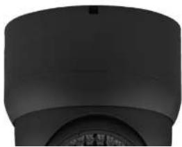
Close-up of a black cylindrical object with a circular base and a small circular top, resembling a mechanical or architectural component (no visible text or symbols)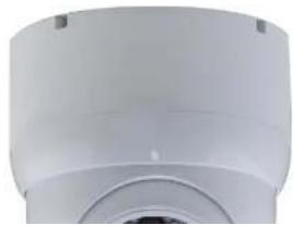
natural_image
Close-up of a white cylindrical mechanical component with a circular opening and mounting holes (no visible text or symbols)PACKAGE CONTENTS
This package contains:
One ST-DWD650IRVP2812-B/W Camera with Junction Box base One installation manual
Note: The ST-DWD650IRVP2812-B/W requires a 12VDC 500mA power supply such as the ST-PS12VDC1A or ST-PS12VDC2A.
PRODUCT DESCRIPTION
The ST-DWD650IRVP2812-B/W is a vandal-proof infrared camera designed around a 1/3" Color SONY Super HAD CCD with 650TVL of resolution, 36 infrared LEDs providing infrared capability up to 90 feet and a 2.8mm – 12mm manual zoom lens. The ball style dome camera provides the installer with the ability to easily adjust the camera's viewing area. The ST-DWD650IRVP2812-B/W is a cost effective surveillance solution for any budget. The included junction box base is convenient for concealing and protecting cable connections.
SPECIFICATIONS
ST-DWD650IRVP2812-B/W
Specifications (Typical)
- Image Sensor
1/3" SONY Super HAD CCD - Pixels (HxV)
811x508 - Scanning System
NTSC - Horizontal Resolution
650TV Lines - Synchronization
Internal, negative sync
INSTALLATION AND OPERATION
1. UNPACKING and HANDLING
Each unit is shipped assembled and factory tested.
Ensure that all accessories are removed from the container before discarding packing material
2. MECHANICAL INSPECTION
Inspect the front and rear of the equipment for shipping damage. Make sure the equipment is clean, and no connectors are broken, damaged, or loose. If equipment appears to be damaged or defective please contact your distributor or Security Tronix at 1-610-429-1511 for assistance.
3. SPECIAL ATTENTION
a. The installer must comply with electrical safety standards. There must be sufficient space between the camera's power supply and video line and any high voltage equipment and/or cables.
b. To help ensure the camera's life and proper operation do not point the camera towards the sun or strong light.
c. Do not install the camera in an environment where the temperature is above 113^ F. The camera should be installed in a cool and spacious environment.
d. Do not install the camera near a magnetic field or a high-power motor.
e. Only use a dry cloth to clean the camera. If there is dirt that is difficult to remove wipe gently with a mild detergent. Never use strong or abrasive detergents.
f. A 12VDC 500mA power supply must be used. AC power cannot be applied. Using a power supply other than 12VDC 500mA will damage the camera.
g. Only qualified installers are allowed to install, test and disassemble the camera.
h. The IR LED angle and lens viewing range are adjusted at the factory. Any change to the camera's lens will affect image quality.
text_image
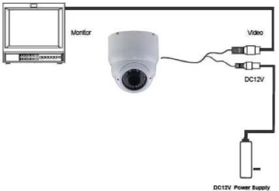
Monitor Video DC12V DC12V Power Supply
* OSD SETTING
| OSD SET | LENS | MANUAL/DC/VIDEO | |
| EXPOSURE | SHUTTER | AUTO, 1/50, 1/250, 1/500, 1/2000, 1/5000, 1/10000, 1/10000, ×1, ×4, ×5, ×16, ×32, ×64, ×128, ×256 | |
| BHORTHNESS | 0-100 | ||
| AOC | LOW/AWBD/AVEG/OWT | ||
| SENSE UP | OR to USE | ||
| BLO | OFF/SLC/DESC | ||
| D-WDR | OFF/DOOR/OUTDOOR | ||
| RETURN | |||
| WHITE BAR | ATW/AWB/AWC/MANUAL/INDOOR/OUTDOOR | ||
| DAY NIGHT | AUTO/COLOR/BW | ||
| MIME | ON/OFF | ||
| SPECIAL | CAM THILL | ON/OFF | |
| D-EFFECT | FREE OR/OFF | ||
| MUTEUR | |||
| D-BOX | |||
| GAMR | |||
| NRC IMAGE | |||
| KEYING | |||
| RESIZE | CAM ID | ||
| ID DISPLAY | |||
| MACRIMATE | |||
| MOTION | ON/OFF | ||
| PRIVACY | OFF | ||
| AREA SELECT | |||
| AREA DISPLAY | |||
| LEFT/RIGHT | |||
| WIDTH | |||
| Top/Bottom | |||
| Height | |||
| Color | |||
6. TROUBLESHOOTING
a. No picture after applying power - (i) check all plugs and cables are securely connected to the proper connectors; (ii) ensure your power supply is providing the correct voltage and current.
b. The picture has ripples - (i) check to see if the power supply is experiencing AC ripple, if so a filter may be required; (ii) determine if the monitor is faulty; (iii) determine if other peripheral equipment is causing ripple and if so make the necessary adjustments.
c. The picture background continuously changes color – a fluorescent lamp's magnetic field may cause color roll, therefore, reduce the number of fluorescent lamps or increase the distance between the camera and the lamps.
d. The picture appears smeared – (i) the power supply voltage level may be unstable, therefore, try another power supply; (ii) ensure the cables are correctly connected and/or the cables are of the correct impedance.
e. Other interference may require a Security Tronix ground loop isolation filter.
f. Additional troubleshooting assistance can be found on-line at www.securitytronix.com in addition to support from Security Tronix sales engineers at 1-800-688-9282.