ST-WD650PTZMINI-12X - Security Camera Security Tronix - Free user manual and instructions
Find the device manual for free ST-WD650PTZMINI-12X Security Tronix in PDF.


| Product Type | High Speed Intelligent Dome PTZ Color Camera |
| Image Sensor | 1/3" Super HAD II Sony Color CCD |
| Resolution | Color 650TVL, Black/White 700TVL |
| Lens | 5-60mm dynamic varifocal lens (12X optical zoom) |
| Effective Picture Elements | NTSC: 976(H) x 494(V) |
| Minimum Illumination | 0.001 Lux |
| Video Output | 1Vpp, 75Ω composite |
| Signal-to-Noise Ratio | 50 dB |
| Pan Range | 360° continuous |
| Tilt Range | 0° ~ 90° |
| Pan Speed | 60° per second |
| Power Requirement | 12 VDC, 1A minimum |
| Operating Temperature | 14°F ~ 113°F (-10°C ~ 45°C) |
| Storage Temperature | 22°F ~ 140°F (-6°C ~ 60°C) |
| Dimensions | 8" x 8.5" (203 x 216 mm) |
| Weight | 2.9 lbs (1.32 kg) |
| Ingress Protection | IP66 rated for outdoor use |
| Communication Protocol | Pelco D / Pelco P (selectable) |
| PTZ Control | RS485 (unshielded twisted pair) +, - |
| On-Screen Display | Full menu for camera and PTZ settings |
| Cleaning | Use dry cloth; mild detergent for stubborn dirt; avoid abrasives |
| Safety | Low voltage product; proper grounding required; use specified power supply only |
Frequently Asked Questions - ST-WD650PTZMINI-12X Security Tronix
User questions about ST-WD650PTZMINI-12X Security Tronix
0 question about this device. Answer the ones you know or ask your own.
Ask a new question about this device
Download the instructions for your Security Camera in PDF format for free! Find your manual ST-WD650PTZMINI-12X - Security Tronix and take your electronic device back in hand. On this page are published all the documents necessary for the use of your device. ST-WD650PTZMINI-12X by Security Tronix.
USER MANUAL ST-WD650PTZMINI-12X Security Tronix
High Speed Intelligent Dome PTZ Color Camera
This is a 12 volt DC camera.

natural_image
Exterior view of a beige security camera with a spherical dome and mounted arm (no text or symbols visible)PACKAGE CONTENTS
This package contains:
One ST-WD650PTZMINI-12X intelligent dome camera
One Mounting Arm
One installation manual
Note: The ST-WD650PTZMINI-12X requires a minimum 12VDC 1000mA (1 Amp) power supply such as the ST-PS12VDC1A or ST-PS12VDC2A.
PRODUCT DESCRIPTION
The ST-WD650PTZMINI-12X is a professional grade, IP-66 rated outdoor dome color camera with pan, tilt and zoom (PTZ) capability. The camera's design allows the saving of all settings in non-volatile memory. The camera features include a 12X optical zoom 5mm - 60mm lens and a Sony Super HAD II Color CCD with 650TVL color / 700TVL B&W resolution.
SPECIFICATIONS
ST-WD650PTZMINI-12X
Specifications (Typical)
| 1. Image Sensor | 1/3" Super HAD II Sony Color CCD |
| 2. Resolution | Color 650TVL, Black 700TVL |
| 3. Lens | 5-60mm dynamic varifocal lens |
| 4. Effective Picture Elements | NTSC:976(H)×494(V) |
| 5. Minimum Illumination | 0.001 Lux |
| 6. Scanning System | 2:1 interlace |
| 7. Video Output | 1Vpp, 75Ω |
| 8. Signal to Noise Ratio | 50dB |
| 9. Synchronous System | Internal, Negative sync. |
| 10. Auto Electronic Shutter | NTSC: 1/60s~1/100,000s, |
| 11. Gama Correction | 0.45 |
| 12. Gain Control | Auto |
| 13. White Balance | Auto / Manual |
| 14. Pan Range | 360° continuous |
| 15. Tilt Range | 0° ~ 90° |
| 16. Pan Speed | 60° / second |
| 17. Power | 12VDC / 1A |
| 18. Storage Temperature | 22°F ~ 140°F |
| 19. Operating Temperature | 14°F ~ 113°F |
| 20. Dimensions | 8" x 8.5" |
| 21. Weight | 2.9 lbs |
INSTALLATION AND OPERATION

This symbol is intended to alert the user to the presence of important operating and maintenance (servicing) instructions.

This symbol is intended to alert the user to the presence of uninsulated "dangerous voltage" within the product's enclosure that may be of sufficient magnitude to constitute a risk of electrical shock.
CAUTION: To reduce the risk of electrical shock do not remove the cover or back of this unit. No user serviceable parts are inside.
CAUTION: To prevent electric shocks and risk of fire hazards, do not use other than specified power source.
1. UNPACKING and HANDLING
Each unit is shipped factory tested.
Ensure that all accessories are removed from the container before discarding packing material
2. MECHANICAL INSPECTION
Inspect the front and rear of the equipment for shipping damage. Make sure the equipment is clean, and no connectors are broken, damaged, or loose. If equipment appears to be damaged or defective please contact your distributor or SecurityTronix at 1-610-429-1511 for assistance.
3. ASSEMBLY
a. Remove the rear mounting plate, using the supplied allen key wrench.
b. Guide the camera dome's wiring harness through the hole in the end of the mounting arm and out through the base of the mount, being careful not to kink or scrape the wires.
c. Feed the stub of the camera dome into the hole in the mounting arm, ensuring that the 3 threaded holes on the camera tube align with the 3 holes in the mounting arm.
d. Using the 4 supplied Phillips head screws, attach the camera dome to the mounting arm.
4. SPECIAL ATTENTION
a. The installer must comply with electrical safety standards. There must be sufficient space between the camera's power supply and video line and any high voltage equipment and/or cables.
b. Do not install the camera in an environment where the temperature is above 114irc F.
c. Do not install the camera near a magnetic field or a high-power motor.
d. Do not mount the camera near a radiator or heater.
e. The installation site and material must fully support the weight of the product.
f. Only use a dry cloth to clean the camera. If there is dirt that is difficult to remove wipe gently with a mild detergent. Never use strong or abrasive detergents.
g. A 12VDC power supply at 1A or higher must be used. Using an AC or other incorrect power supply will damage the camera.
h. Only qualified installers are allowed to install, test and disassemble the camera.
i. The camera is a low voltage product. If installed outdoors proper safety and lightning grounding are required.
WIRING CONNECTIONS
a. Connect the power supply's 12VDC plug to the camera's power jack.
b. Connect the camera's BNC connector to a DVR (or monitor) with a 75Ω coaxial video cable.
c. Connect unshielded twisted pair wire (UTP) between the camera's RS485 wires and the PTZ controller. The purple wire is positive (A, +) and the grey wire is negative (B, -). Be sure the same polarity is used at each end of the connection.
d. Connect the power supply's AC plug to a suitable AC wall outlet.

flowchart
graph TD
    A["Camera"] -->|b. Video| B["Display Module"]
    A -->|c. TV| C["Network"]
    B -->|d. Power Supply| D["Power Supply"]
    style A fill:#f9f,stroke:#333
    style B fill:#ccf,stroke:#333
    style C fill:#cfc,stroke:#333
    style D fill:#fcc,stroke:#333
5. SETTING CAMERA ADDRESS, PROTOCOL and BAUD RATE
The camera's address, protocol and baud rate are set using the camera's On Screen Display menu.
When the camera powers up, it will display the default protocol, address and baud rate, which is:
- Protocol: Pelco D
- Address: 1
- Baud rate: 9600
To access the menu, set your PTZ controller to match these default settings then press "Iris Open" or "Open" on your PTZ controller.
The MAIN MENU will display:

Use the UP and DOWN buttons of your controller to highlight
The PROTOCOL SETUP menu will display:

Use the UP & DOWN buttons to select a parameter to change and use the LEFT & RIGHT buttons to change the value. Then use the DOWN button to highlight EXIT MENU and press OPEN to exit the menu.
NOTE:
The moment this menu is exited, the new settings will take place and the PTZ controller will not operate the camera until it is set to match the new settings of the camera.
NOTE:
9600 baud is only recommended for very short cable runs; 30 \~ 40 ft or less. For best overall PTZ operation, it is strongly recommended to use a baud rate of 2400 bps.
6.0 On Screen Display (OSD) Menus
This camera employs an on screen display system to facilitate making changes to the camera's settings.
The OSD is accessed by using the IRIS OPEN button (sometimes labeled "OPEN" or "IRIS +") of a Pelco D-compliant PTZ controller or by using the controller to CALL preset 95.
When the menu appears it will display the MAIN MENU page:

The menu is navigated by using the UP & DOWN PTZ buttons to move up and down through the menu, the RIGHT & LEFT buttons to change values and the OPEN button to enter a sub-menu or select a function such as EXIT MENU.
6.1 CAMERA SETUP MENU
From the MAIN MENU, use the DOWN button to highlight CAMERA SETUP and use the OPEN button to access the CAMERA SETUP menu.
The first page of two CAMERA SETUP menu pages will display:

Some menu options will have an arrow indicating that a sub-menu is available. To access a sub-menu, highlight the menu item and press OPEN.
From this page of the CAMERA SETUP MENU, highlight SHUTTER / AGC to access the SHUTTER and Auto Gain Control functions, which control how the camera will react to various lighting conditions. Press OPEN to enter the sub-menu.
The SHUTTER / AGC MANUAL sub menu will display:

Use the UP, DOWN, LEFT & RIGHT buttons to navigate to the desired function and change the setting, then navigate to RETURN and press OPEN to return to page 1 of the CAMERA SETUP MENU.
NOTE:
Manual setup of the shutter and AGC functions is only recommended for extremely bright or dark conditions where the light levels are consistent. In most cases using the AUTO shutter and AGC settings is preferred.
To use AUTO shutter settings, change the SHUTTER / AGC setting to AUTO and press OPEN to enter the AUTO SHUTTER sub menu:
The SHUTTER / AGC AUTO sub menu will display:

Use the UP, DOWN, LEFT & RIGHT buttons to navigate to the desired function and change the setting, then navigate to RETURN and press OPEN to return to page 1 of the CAMERA SETUP MENU.
6.2 WHITE BAL (white balance) MENU
From page 1 of the CAMERA SETUP MENU, highlight WHITE BAL to access the white balance functions, which affects how the camera will reproduce colors
There are 6 modes of white balance operation and 4 of the 6 choices have sub menus. USER 1 and USER 2 sub menus are identical in operation:
- MANUAL
- ATW
- USER 1
- USER 2
Use the LEFT & RIGHT buttons to select the desired white balance mode and press OPEN to enter the sub-menu.
WHITE BALANCE MANUAL MODE:

Use the LEFT & RIGHT buttons to change the WB LEVEL, then select RETURN and press OPEN to return to the CAMERA SETUP MENU page 1.
WHITE BALANCE ATW MODE:

Use the LEFT & RIGHT buttons to change the SPEED, DELAY, ATW FRAME and EBVIRONMENT parameters, then select RETURN and press OPEN to return to the CAMERA SETUP MENU page 1.
NOTE:
In most cases using the default values of the ATW settings is preferred.
WHITE BALANCE USER 1 & USER 2 MODE:

The USER 1 and USER 2 menus are identical in operation and provide the same settings as ATW.
Use the LEFT & RIGHT buttons to change the SPEED, DELAY, ATW FRAME and EBVIRONMENT parameters, then select RETURN and press OPEN to return to the CAMERA SETUP MENU page 1.
6.3 BACKLIGHT
From page 1 of the CAMERA SETUP MENU select BACKLIGHT and use the LEFT & RIGHT buttons to choose:
- OFF – No backlighting compensation is used.
- BLC – Backlighting compensation is used. The intensity of bright areas is reduced and the gain is increased for dark areas to bring more definition to foreground objects when there is a bright light present in the background.
- HLC – bright areas are “blacked out” to prevent oversaturation of the camera image.
6.4 PICT (picture) ADJUST
From page 1 of the CAMERA SETUP MENU select PICT ADJUST and press OPEN to enter the sub menu.
The PICTURE ADJUST MENU will display:

Use the UP, DOWN, LEFT & RIGHT buttons to select and change the MIRROR, BRIGHTNESS, CONTRAST, SHARPNESS, HUE and GAIN parameters, then select RETURN and press OPEN to return to the CAMERA SETUP MENU page 1.
NOTE:
The MIRROR function flips the camera's image horizontally to produce a "mirror image" of the actual camera view.
6.5 ATR (Adaptive Tone Reproduction)
From page 1 of the CAMERA SETUP MENU select ATR. If ATR is set to ON a sub menu will become available. Press OPEN and the ATR sub menu will display:

where, for instance, both low-luminance areas and high-luminance areas exist in the same picture.
Use the UP, DOWN, LEFT & RIGHT buttons to select and change the LUMINANCE and CONTRAST parameters, then select RETURN and press OPEN to return to the CAMERA SETUP MENU page 1.
6.6 MOTION DET (motion detection)
The Motion Detection feature is not implemented on this camera model.
6.7 CAMERA SETUP MENU PAGE 2
From page 1 of the CAMERA SETUP MENU select NEXT and CAMERA SETUP MENU page 2 will display:


6.8 PRIVACY
The PRIVACY feature is not implemented on this camera model.
6.9 DAY / NIGHT
From page 2 of the CAMERA SETUP MENU select DAY / NIGHT. Use the LEFT & RIGHT buttons to choose one of 3 modes:
- COLOR
• AUTO
• B/W
When set to COLOR, the camera is forced into color mode at all times, regardless of lighting conditions.
The AUTO and B/W options each have a sub menu.
To use AUTO operation, choose AUTO then press OPEN and the DAY / NIGHT AUTO sub menu will display:

Use the UP, DOWN, LEFT & RIGHT buttons to select and change the 4 available parameters, then select RETURN and press OPEN to return to the CAMERA SETUP MENU page 2.
6.10 DAY / NIGHT
From page 2 of the CAMERA SETUP MENU select
To use B / W operation, choose B / W then press OPEN and the DAY / NIGHT B / W sub menu will display:
| B/W | |
| BURST | ON |
| RETURN: |
Use the UP DOWN LEFT & RIGHT buttons to select either ON or
6.11 NR (Noise Reduction)
From page 2 of the CAMERA SETUP MENU select NR and press OPEN. The NR sub menu will display:
| NR | ||
| NR MODE | OFF | 4 |
| Y LEVEL | = | |
| C LEVEL | = | |
| RETURN: | ||
Use the UP, DOWN, LEFT & RIGHT buttons to select either Y, C, Y&C or OFF for the NR parameter, then Adjust the Y and/or C levels for the best picture. Select RETURN and press OPEN to return to the CAMERA SETUP MENU page 2.
6.12 CAMERA ID
From page 2 of the CAMERA SETUP MENU select CAMERA ID and select either NO for the camera to not display a name, or ON to display a name. To ENTER a name, select ON and press OPEN to display the CAMERA ID sub menu:

position the cursor and select characters. Press OPEN to set each character in the name, then select RETURN and press OPEN to return to the CAMERA SETUP MENU page 2.
6.13 LANGUAGE
From page 2 of the CAMERA SETUP MENU move the cursor to LANGUAGE and use the LEFT & RIGHT buttons to select a language for the camera's OSD. Choices include ENGLISH, FRENCH, SPANISH, RUSSIAN, etc.
When finished, select RETURN and press OPEN to return to the CAMERA SETUP MENU page 2.
6.14 CAMERA RESET
This function will reset all CAMERA MODULE functions back to the factory default settings. This is useful if many parameters have been changed and the user wishes to get a 'fresh start' for minor adjustments.
This function only resets the camera module, which all functions in sections 6.1 through 6.12 above. This will NOT reset an tour or preset information. To reset the movement functions of the camera, please see section XXXXX below.
To reset the camera module: From page 2 of the CAMERA SETUP MENU move the cursor to CAMERA RESET. Press OPEN to begin the reset. This will take several seconds to complete and the OSD will display the status of the reset.
NOTE:
This function ERASES ALL SETTING MADE BY THE USER TO THE CAMERA MODULE. All camera settings must be manually set up again.
7.0 FOCUS SETUP MENU
From the MAIN MENU, use the DOWN button to highlight FOCUS SETUP and use the OPEN button to access the FOCUS SETUP menu.
The FOCUS SETUP menu page will display:

Use the UP & DOWN buttons to select FOCUS TYPE and use the LEFT & RIGHT buttons to select either AUTO or MANUAL for the focus mode.
NOTE:
"AUTO" is the factory default and it is the recommended setting for this parameter. Manual focus would require the operator to manually focus the lens on each object when the camera changes positions.
7.1 AF (Auto Focus) AFTER MOVE
When set to ON, this causes the lens to enact an automatic focus adjustment each time the camera is moved to a new view or when the zoom level changes.
When set to OFF, the camera will retain whatever focus setting it had previous to the move or zoom level change.
7.2 PRESET LOAD ZOOM
When set to ON, recalling a preset on the camera will set the camera to the PAN position, TILT position and ZOOM level stored within that preset.
When set to OFF, recalling a preset on the camera will set the camera to the PAN position and TILT position stored within that preset, but will ignore the ZOOM level stored in the preset.
7.3 AUTO CHECK FOCUS
When set to ON, the camera will periodically check the focus status and re-focus if needed. The period of time is set in the AUTO CHECK TIME parameter (# 7.3 below). In order for this to work, the focus mode must be set to AUTO (# 7.0 above).
7.4 AUTO CHECK TIME
This is the amount of time, measured in seconds, that the camera will wait after receiving a command before it will check the focus status. It is adjustable from 0 thru 255 seconds.
7.5 DISPLAY ZOOM TIMES
When set to ON, the camera will show the zoom multiplication in the OSD, superimposed over the video; e.g. 1X, 4X etc up to 12X optical zoom.
8.0 PAN TILT SETUP
From the MAIN MENU, use the DOWN button to highlight PAN TILT SETUP and use the OPEN button to access the sub menu. The PAN TILT SETUP menu page will display:

8.1 PAN TILT PRESET
Use the UP & DOWN buttons to select PAN TILT PRESET and use the LEFT & RIGHT buttons to select either NORMAL, FAST or EXACT for the preset mode. NORMAL will cause the camera to move normally from preset to preset as they are called, either manually or in a tour (pattern). FAST will cause the camera to move from preset to preset at the fastest rate it can move, which may cause it to land slightly off of the preset's original position. EXACT will cause the camera to double-check its position once it arrives at a preset. This gives the most correct positioning but
8.2 TILT LIMIT SET
Tilt limit will set a specific point, beyond which the camera will not tilt.
To enable a tilt limit, first exit the menu and use the PTZ controller to set the camera to the vertical height (tilt) to be used as the limit.
Enter the camera menu and use the DOWN button to highlight PAN TILT SETUP, then TILT LIMIT SET. Press the OPEN button to set the current tilt position as the tilt limit. To remove the tilt limit, use the next function described in # 8.2 TILT LIMIT RESET, below.
8.3 TILT LIMIT RESET
This function removes any tilt limit was set in the previous step above. Use the UP & DOWN buttons to select TILT LIMIT RESET and press the OPEN button to remove the tilt limit.
8.4 PAN TILT LIMIT SPEED
The number set for this parameter will determine the maximum speed at which the camera can move (pan or tilt). This can be useful if the PTZ controller being used does not have the ability to control the camera at lower speeds. The value ranges from 1 \~ 63, with 63 being 100% full speed operation.
8.5 ZOOM LIMIT SPEED
The number set for this parameter will determine the maximum speed at which the camera's lens can zoom. The value ranges from 1 \~ 63, with 63 being 100% full speed operation. 63 is the recommended setting.
9.0 PATTERN SETUP
From the MAIN MENU, use the DOWN button to highlight PATTERN SETUP and use the OPEN button to access the sub menu.
The PATTERN SETUP menu page will display:
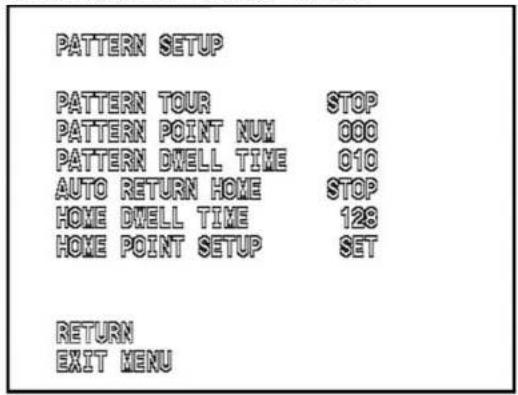
9.1 PATTERN TOUR
Use the UP & DOWN buttons to select PATTERN TOUR and use the LEFT & RIGHT buttons to set it to either START or STOP.
When set to START, upon exiting the menu the camera will begin its tour, according to the settings of PATTERN POINT NUM and PATTERN DWELL TIME, #'s 9.2 and 9.3 below.
When set to STOP, the camera will stop running its tour when the menu is exited.
9.2 PATTERN POINT NUM
Pattern point number sets the highest preset number which the tour will include. The tour will only include preset numbers from 1 through 32 which have been stored into the camera.
Example 1: If presets 1, 2 and 3 have bet set and stored in the camera and the PATTERN POINT NUMBER has been set to any number equal to "3" or higher, the tour will use preset points 1, 2 and 3. If the PATTERN POINT NUMBER is set to "2", the tour will only include presets 1 & 2.
Example 2: If presets 2, 7 and 10 have bet set and stored in the camera and the PATTERN POINT NUMBER has been set to any number equal to "10" or higher, the tour will use preset points 2, 7 and 10 and ignore all other presets from 1 thru 10 which have not been set. If the PATTERN POINT NUMBER is set to "8", the tour will only include presets 2 & 7.
Use the UP & DOWN buttons to select PATTERN POINT NUM and use the LEFT & RIGHT buttons to set it to the desired preset number.
9.3 PATTERN DWELL TIME
Pattern dwell time sets the amount of time in seconds that the camera will stay at each preset of the tour before moving on to the next preset. It is adjustable from 5 to 255.
Use the UP & DOWN buttons to select PATTERN DWELL TIME and use the LEFT & RIGHT buttons to set it to the desired dwell time.
9.4 AUTO RETURN HOME
Use the UP & DOWN buttons to select AUTO RETURN HOME and use the LEFT & RIGHT buttons to set it to either START or STOP. When set to START, the camera will be enabled to return to a user-selected home point after a lack of user input determined by HOME DWELL TIME described in # 9.5, below.
When set to STOP, the camera will not return to its home point.
9.5 HOME DWELL TIME
This is the amount of time, in seconds, that the camera will wait after receiving its last PTZ command before returning to the user-selected HOME point. The home point is set using # 9.6 HOME POINT SETUP, below.
Use the UP & DOWN buttons to select HOME DWELL TIME and use the LEFT & RIGHT buttons to set it to the desired dwell time.
9.6 HOME POINT SETUP
To set the HOME POINT position for the camera, exit the menu and use the PTZ controller to direct the camera to view the point which you would like to be the HOME POINT.
Re-enter the menu, and navigate back to this parameter, then press OPEN to lock in the current camera view as the HOME POINT.
10.0 PROTOCOL SETUP
NOTE: This menu is used instead of DIP switches to set the communication parameters for the camera. After making a change and exiting the menu, the controller must be set to match the camera before PTZ control can be regained.
From the MAIN MENU, use the DOWN button to highlight PROTOCOL SETUP and use the OPEN button to access the sub menu.
The PROTOCOL SETUP menu page will display:

9.1 PROTOCOL
Use the DOWN button to select PROTOCOL. Use the LEFT & RIGHT buttons to select either PELCO-D or PELCO-P. All SecurityTronix PTZ controllers use the PELCO-D protocol. Check the owner's manual of your PTZ controller to determine if it is
9.2 ADDRESS
Use the DOWN button to select ADDRESS. Use the LEFT & RIGHT buttons to select an address for the camera. The range is 1 thru 255.
9.3 BAUDRATE
Use the DOWN button to select BAUDRATE. Use the LEFT & RIGHT buttons to select a baud rate for the camera. The choices are:
NOTE: When using lower baud rates, longer cables can be used for PTZ control, at the expense of slower data throughput. For this reason, SecurityTronix recommends using a baud rate of 2400 for most installations.
11.0 RESET MENU SETUP
NOTE: Using these reset commands will delete all user-entered settings in the camera and return it to the factory-default settings. This is useful for getting back to square one with the settings rather than undo all settings one by one, but it will erase ALL user settings in one operation. Use caution when resetting the camera back to factory settings. All user-entered presets, tour and preferences will be reset.
From the MAIN MENU, use the DOWN button to highlight RESET MENU SETUP and use the OPEN button to access the sub menu. The RESET MENU SETUP menu page will display:

11.1 RESET MENU SETUP
This function resets all values of all menus to the factory original
check and/or reset the settings. This will not erase any presets which were stored in the camera. Use the DOWN button to select RESET MENU SETUP. Press OPEN to initialize the reset procedure. The OSD will prompt that the operation is proceeding and when it is complete.
11.2 FACTORY DEFAULT SET
This function resets all values of all menus to the factory original settings AS WELL as erase all presets and tour settings which were stored in the camera. This is useful if the camera is doing something unusual and it would be too difficult to go through all pages of the menus to check and/or reset the settings. Use the DOWN button to select FACTORY DEFAULT SET. Press OPEN to initialize the reset procedure. The OSD will prompt that the operation is proceeding and when it is complete.
SET PRESET POINT NUMBERS
| Preset # | Funcon |
| 1 ~ 32 | Set preset points 1 through 32 |
CALL PRESET POINT NUMBERS
| 1 ~ 32 | Go to Preset Points 1 through 32 |
CLEAR PRESET POINT NUMBERS
| 1 ~ 32 | Clear preset points 1 through 32 |
6. TROUBLESHOOTING
a. No picture after applying power – (i) check all plugs and cables are connected to the proper connectors: (ii) ensure your power supply is providing the correct voltage and enough current.
b. The picture has ripples - (i) Check to see if the power supply is experiencing AC ripple. If so, a filter may be required. (ii) Determine if the monitor is faulty. (iii) Determine if other peripheral equipment is causing the ripple and if so make the necessary adjustments.
c. The picture background continuously changes color - A fluorescent lamp's magnetic field may cause color roll. If possible, increase the distance between the camera and any fluorescent lamps in the vicinity.
d. The picture appears smeared - (i) The power supply voltage level may be unstable. Try another power supply. (ii) Ensure the cables are correctly connected and of the right impedance.
e. Other interference may require the use of a SecurityTronix ground loop isolation filter.
f. Power is on but the controller does not work – (i) Check to make sure the DIP switches are all set correctly for address, baud rate and protocol. (ii) Check that the RS485 wires at the camera and controller have correct polarities. (iii) Check the integrity and continuity of the Unshielded Twisted Pair (UTP) cable.
Additional troubleshooting assistance can be found online at www.securitytronix.com or email us at support@securitytronix.com or call 800 688-9282
- PACKAGE CONTENTS
- PRODUCT DESCRIPTION
- SPECIFICATIONS
- INSTALLATION AND OPERATION
- UNPACKING and HANDLING
- MECHANICAL INSPECTION
- ASSEMBLY
- SPECIAL ATTENTION
- WIRING CONNECTIONS
- SETTING CAMERA ADDRESS, PROTOCOL and BAUD RATE
- NOTE:
- On Screen Display (OSD) Menus
- CAMERA SETUP MENU
- WHITE BAL (white balance) MENU
- BACKLIGHT
- PICT (picture) ADJUST
- ATR (Adaptive Tone Reproduction)
- MOTION DET (motion detection)
- CAMERA SETUP MENU PAGE 2
- PRIVACY
- DAY / NIGHT
- DAY / NIGHT
- NR (Noise Reduction)
- CAMERA ID
- LANGUAGE
- CAMERA RESET
- FOCUS SETUP MENU
- AF (Auto Focus) AFTER MOVE
- PRESET LOAD ZOOM
- AUTO CHECK FOCUS
- AUTO CHECK TIME
- DISPLAY ZOOM TIMES
- PAN TILT SETUP
- PAN TILT PRESET
- TILT LIMIT SET
- TILT LIMIT RESET
- PAN TILT LIMIT SPEED
- ZOOM LIMIT SPEED
- PATTERN SETUP
- PATTERN TOUR
- PATTERN POINT NUM
- PATTERN DWELL TIME
- AUTO RETURN HOME
- HOME DWELL TIME
- HOME POINT SETUP
- PROTOCOL SETUP
- PROTOCOL
- ADDRESS
- BAUDRATE
- RESET MENU SETUP
- RESET MENU SETUP
- FACTORY DEFAULT SET
- TROUBLESHOOTING
Brand : Security Tronix
Model : ST-WD650PTZMINI-12X
Category : Security Camera