Pro-Pak HWB2-84RA20 - Security Camera Ganz - Free user manual and instructions
Find the device manual for free Pro-Pak HWB2-84RA20 Ganz in PDF.

User questions about Pro-Pak HWB2-84RA20 Ganz
0 question about this device. Answer the ones you know or ask your own.
Ask a new question about this device
Download the instructions for your Security Camera in PDF format for free! Find your manual Pro-Pak HWB2-84RA20 - Ganz and take your electronic device back in hand. On this page are published all the documents necessary for the use of your device. Pro-Pak HWB2-84RA20 by Ganz.
USER MANUAL Pro-Pak HWB2-84RA20 Ganz
natural_image
Two metallic cylindrical mechanical components with flanges and central openings, shown against a plain background (no text or symbols visible)Instructions for Use
IMPORTANT SAFEGUARDS
-
Read Instructions - All the safety and operating instructions should be read before the unit is operated.
-
Retain Instructions - The safety and operating instructions should be retained for future reference.
-
Heed Warnings - All warnings on the unit and in the operating instructions should be adhered to.
-
Follow Instructions - All operating and use instructions should be followed.
-
Cleaning - Unplug the unit from the outlet before cleaning. Do not use
liquid cleaners or aerosol cleaners. Use a damp cloth for cleaning. 6. Attachments - Do not use attachments not recommended by the product manufacturer as they may cause hazards.
- Accessories - Do not place this unit on an unstable stand, tripod, bracket, or mount. The unit may fall, causing serious injury to a person and serious damage to the unit. Use only with a stand, tripod, bracket, or mount recommended by the manufacturer or sold with the product. Any mounting of the unit should follow the manufacturer's instructions and should use a mounting accessory recommended by the manufacturer.

An appliance and car combination should be moved with care. Quick stops, excessive force, and uneven surfaces may cause the appliance and car combination to overturn.
-
Ventilation - Openings in the enclosure, if any, are provided for ventilation, to ensure reliable operation of the unit, and to protect it from overheating. These openings must not be blocked or covered. This unit should not be placed in a built-in installation unless proper ventilation is provided or the manufacturer's instructions have been adhered to.
-
Power Sources - This unit should be operated only from the type of power source indicated on the marking label. If you are not sure of the type of power supply you plan to use, consult your appliance dealer or local power company. For units intended to operate from battery power or other sources, refer to the operating instructions.
-
Grounding or Polarization - This unit may be equipped with a polarized alternating-current line plug (a plug having one blade wider than the other). This plug will fit into the power outlet only one way. 'I this is a safety feature. If you are unable to insert the plug fully into the outlet, try reversing the plug. If the plug should still fail to fit, contact your electrician to replace your oblique outlet. Do not defeat the safety purpose of the polarized plug.
Alternately, this unit may be equipped with a 3-wire grounding-type plug, a plug having a third (grounding) pin. This plug will only fit into a grounding-type power outlet. This is a safety feature. If you are unable to insert the plug into the outlet, contact your electrician to replace your absolute outlet. Do not defeat the safety purpose of the grounding-type plug.
-
Power Cord Protection - Power supply cords should be routed so that they
-
Power Lines - An outdoor system should not be located in the vicinity of overhead power lines or other electric light or power circuits or where it can fall into such power lines or circuits. When installing an outdoor system, extreme care should be taken to keep from touching such power lines or circuits as contact with them might be fatal. U.S.A. models only refer to the National Electrical Code Article 820 regarding installation of CATV systems.
-
Overloading - Do not overload outlets and extension cords as this can result in a risk of fire or electric shock.
-
Object and Liquid Entry - Never push objects of any kind into this unit through openings, as they may touch dangerous voltage points or short out parts that could result in a fire or electric shock. Never spill liquid of any kind on the unit.
-
Servicing - Do not attempt to service this unit yourself as opening or removing covers may expose you to dangerous voltage or other hazards. Refer all servicing to qualified service personnel.
-
Damage Requiring Service - Unplug the unit from the outlier and refer servicing to qualified service personnel under the following conditions: a. When the power supply cord or plug is damaged,
b. If liquid has been spilled or objects have fallen into the unit.
c. If the unit has been exposed to rain or water.
d. If the unit does not operate normally by following the operating instructions. Adjust only those controls that are covered by the operating instructions, as an improper adjustment of other controls may result in damage and will often require extensive work by a qualified technician to restore the unit to its normal operation.
e. If the unit has been dropped or the cabiner has been damaged.
f. When the unit exhibits a distinct change in performance—this indicates a need for service.
-
Replacement Parts - When replacement parts are required, be sure the service technician has used replacement parts specified by the manufacturer or have the same characteristics as the original part. Unauthorized substitutions may result in fire, electric shock, or other hazards.
-
Safety Check - Upon completion of any service or repairs to this unit, ask the service technician to perform safety checks to determine that the unit is in proper operating condition.
-
Cox Grounding - If an outside cable system is connected to the unit, he sure the cable system is grounded. U.S.A. models only—Section 810 of the National Electrical Code, ANSI/NEPA No.70-1981, provides information with respect to proper grounding of the mount and supporting structure, grounding of the coax to a discharge unit, size of grounding conductors, location of discharge unit, connection to grounding electrodes, and requirements for the grounding electrode.
-
Lightning - For added protection of this unit during a lightning storm, or when it is left unattended and unused for long periods of time, unplug it from the wall outlets and disconnect the cable system. This will prevent damage to the unit due to lightning and power line surges.
SAFETY PRECAUTIONS
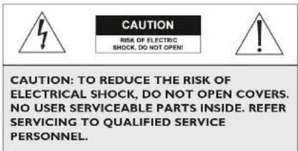
CAUTION: TO REDUCE THE RISK OF ELECTRICAL SHOCK, DO NOT OPEN COVERS. NO USER SERVICEABLE PARTS INSIDE. REFER SERVICING TO QUALIFIED SERVICE PERSONNEL.
This label may appear on the bottom of the unit due to space limitations.

The lightning flash with an arrowhead symbol within an equilateral triangle is intended to alert the user to the presence of uninsulated "dangerous voltage" within the product's enclosure that may be of sufficient magnitude to constitute a risk of electric shock to persons.

The exclamation point within an equilateral triangle is intended to alert the user to presence of important operating and maintenance (servicing) instructions in the literature accompanying the appliance.
SECURITE
DANGER: POUR ÉVITER TOUT RISQUE D'ÉLECTROCUTION, NE PAS OUVRIR LE BOÎTIER. IL N'Y A PAS DE PIÈCES REMPLACABLES À L'INTÉRIEUR, POUR
1 UNPACKING ....4
2 ACCESSORIES ....4
2.1 Sunshields 4
2.2 Tamper Proof Kit 4
3 SERVICE....4
4 CARE AND MAINTENANCE ....4
5 DESCRIPTION 4
6 INSTALLATION 4
6.1 Model Designation ....4
6.2 Maximum Camera/Lens Size ....4
6.3 Tools Required 4
6.4 Cable Requirements 5
6.5 Housing Mounting....5
6.6 Cover Removal 5
6.7 Camera/Lens Installation 5
6.8 Camera/Lens Wiring ....6
6.9 Video Coax Connection 7
6.10 Lens Wiring 7
6.11 Camera/Lens Adjustment 7
6.12 Final Assembly 7
6.13 Fuse Replacement....8
7 EXPLODED VIEW....8
7.1 Parts List 8
I UNPACKING
Unpack carefully. This is mechanical equipment and should be handled with care.
Check for the following:
Housing (with correct model number).
„Hardware Kit - H-1 & H-2 Models:
1 1/4-20 x 3/8-in Button Head Screw.
2 1/4-20 x 1/2-in Button Head Screw.
2 1/4-in Spring Washers.
1 5/16-in Flat Washer.
2 Fittings, 3/8-in NPT.
2.2 Tamperproof Kit
Contains tamper resistant screws and bit key to tamperproof up to five housings.
TPK 1: For all H Series Housings.
3 SERVICE
If the unit ever needs repair service or parts, the customer should contact the company from which the unit was purchased for authorization to return and shipping instructions.
4 CARE AND MAINTENANCE
Regularly scheduled maintenance will help prolong the operation life of this unit. Clean the viewing window as needed with a mild, nonabrasive detergent in water and a soft cloth.
5 DESCRIPTION
The H Series Housings are smart stylized housings for indoor and outdoor use. These housings meet customers' demands for an attractive housing that is both cost competitive and easy to install.
6 INSTALLATION
This installation should be made by qualified service personnel and conform to the National Electrical Code and applicable local codes.
6.1 Model Designation
| Model No. | Description | Voltage | Use with Camera Models with These Voltage Ranges |
| H-1 | Housing | ---- | 24 VAC or 12 VDC |
| H-2 | Housing with heater | 24/23 | 24 VAC |
| H-3 | Housing with heater/blower | 24/25 | 24 VAC |
- The heater operates at 24 VAC, 50/60 Hz and requires 15 W of power.
Do Not Exceed 30 VAC Input on 24 VAC models. Operation above 30 VAC violates low voltage operation (Class 2
Specifications). Normal operation is 24 VAC.
6.4 Cable Requirements
Video Transmission (Coaxial)
Cable Type: RG-59/U for runs < 300 m (1000 ft).
RG-11/U for runs < 600 m (2000 ft).
Cable Size: Outside diameter between
4.6 mm (0.181-in) - 7.9 mm (0.312-in).
Cable Shape: Round.
Shield: > 93% Braided Copper Shield.
Center Conductor: Stranded Copper Center.
DC Resistance: < 15 Ohms/1000 (RG-59/U).
≤ 6 Ohms/1000 (RG-11/U).
Cable Impedence: 75 Ohm.
Agency Rating: UL
Environmental: Outdoor rated.
Temperature Rating: ≥ 80 °C.
Sources: Belden 9259.
Belden 9238.
Input Power Cord - North American
Cable Type: SJTOW-A rated.
Cable Size: Outside diameter between
4.3 mm (0.170 in) - 11.9 mm (0.470 in).
Cable Shape: Round.
Conductors: 3 conductor version and
2 conductor version.
Agency Rating: UL/C.S.A., UL VW-1.
Environmental: Outdoor rated.
Temperature Rating: 105 °C.
Voltage Rating: 300 V
Sources: Belden 19506.
Belden 19509.
Northwire 573939.
Input Power Cord - European
Cable Type: H05RN-F3G0.75 and
H05RN-F3G1.00.
Cable Size: Outside diameter between
4.3 mm (0.170 in) - 11.9 mm (0.470 in).
6.5 Housing Mounting
-
Use the two 1/4-20 x 0.50-inch screws and 1/4-in spring washers provided in the hardware kit to mount the housing to a mount or a pan/tilt. The spring washers must be used for the screws to thread properly.
-
The outer most set of 1/4-20 threaded holes are for mounting to feed-through mounts and the inner most 1/4-20 holes are for mounting to all other mounts and pan/tilts.
6.6 Cover Removal
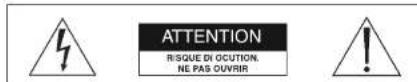
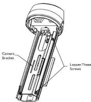
- Loosen the top two screws on the rear of the housing. These screws are captive and will not come out all the way. Do not remove the bottom two screws. See Figure 1.
text_image
Loosen These Screws Do Not RemoveFigure 1: Loosening Captive Screws
- Grasp the housing's front cap and pull forward. Do not squeeze the cover itself. This will make it difficult to slide off the cover. See Figure 2.
Grasp Here—

text_image
Camera Bracket Loosen These ScrewsFigure 3: Removing the Camera Bracket
- Remove the camera bracket from the base. If you are using the feed-through feature, refer to section 6.8.3 at this time.
Mounting fixed lens cameras in H Series Housings
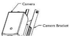
3a. Attach the lens to the camera.
3b. Use the 1/4-20 x 3/8-inch screw to mount the camera to the camera bracket. The lens should extend approximately 6 mm (0.25-in) from the front of the camera bracket. See Figure 4.
Figure 4: Attaching the Camera

Be sure to securely tighten all fittings to ensure a liquid-tight seal. Failure to do so could allow water to enter the housing and damage the camera and lens.
If a sealant is to be used, be sure it is a neutral cure type. Sealants that release acetic acid may harm camera electronics.

Use of "drip loops" is recommended on the wiring outside of the rear end cap.
6.8.2 Conduit
These housings are designed to allow conduit to be directly connected.
- Remove the rear fittings and attach the conduit and conduit fittings directly to the housing rearcap. The holes accept 1/2-in conduit fittings and PG 13.5 conduit fittings. Any unused holes can be covered using the plugs provided in the hardware kit.
6.8.3 Feed-through Wiring
These housings have the capability of having the cabling feed through the foot of the housing. This requires the use of feed-through mounts like the WB-1, WB-2, & JB-1.
- Prior to mounting the camera. Remove the two dome plugs located inside the housing. See Figure 5.
Figure 5: Feed-through Wiring
-
Screw the two 3/8-in NPT fittings into the foot of the housing.
-
Pull the cabling through the fittings and into the housing. Tighten the fitting to 4.0 N-m to 4.5 N-m (35 in-lb to 40 in-lb). This torque rating is approximately 1 to 1 1/2 turns past the point the firing starts to grip the wire. Failure to do so will result in water damage to all electronic parts.
6.8.4 Power Connections
Power connection into the housings is to be supplied through a minimum type UL Standard "SJ" cord acceptable for outdoor use. Installation must conform to acceptable NEC and local codes. For 24 volt cameras, use the chart below for selecting the proper wire size.
Recommended Maximum Cable Lengths for Housings Equipped with 24 Volt Cameras, Heaters, and Blowers
Wire Size Housing Distance
| mm ^2 | AWG meters feet | ||
| 0,5 20 28,6 94 | |||
| 1 | 1 | 8 | 45.7 150 |
| 1,5 16 70.1 230 | |||
| 2,5 14 115.5 379 | |||
| 4 | 1 | 2 | 183.8 603 |
| 6 | 1 | 0 | 292.6 960 |
| 10 8 464.2 1523 | |||
Note: The use of wire sizes larger than 1.5 mm ^2 (14 AWG) will require a splice in order to accommodate the terminal block.
- Install one of the large 1/2-in NPT fittings into one of the holes in the rear cap. The terminal block side is preferable. If you are using the feed-through option, ignore this step.
- Route the power cable through the fitting in the rear cap or one of the feed-through fittings in the foot.
- The terminal block provided on H-1 & H-2 units accepts wire ranging from 20 to 14AWG or 1.5 mm ^2 . The terminal block provided on /H-3 units accepts larger wire ranging from 18 to 12AWG or 2.5 mm ^2 . When using larger wire sizes, splice to a smaller size wire at the terminal block end. The splice may need to be enclosed in a junction box if it does not pass through the fittings.
- On heater and heater/blower units, make sure the heater and fan wires stay connected to the terminal.
- A screw/terminal lug is provided for securing a safety ground. To attach the safety grounding wire (green 115 volt, green/yellow 230 volt), first unscrew the terminal lug and
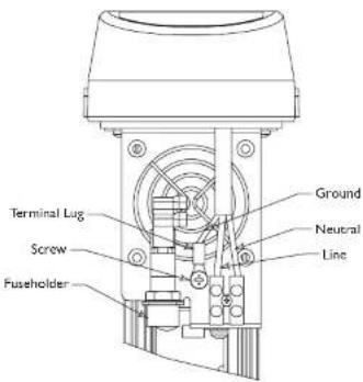
text_image
Terminal Lug Screw Fuseholder Ground Neutral LineFigure 7: Power Connections - Fan Units
Be sure to securey tighten all fitting s to ensure a liquid-tight seal. Failure to do so could allow water to enter the housing and damage the camera and lens.
6.9 Video Coax Connection
WARNING: Only use the cables specified under "INSTALLATION. Cable Requirements" for wiring of the video coax connection.
- Install a 1/2-in NPT fitting into the remaining hole in the rear cap.
- Route the video coax cable through one of the fittings installed in step 1 or one of the feed-through fittings in the base.
-
Attach BNC connector to the coax and connect it to the camera. Pull excess wire out of the housing and tighten the
-
If installing a zoom lens, insert the lens control cable through the last fitting at the rear of the housing. Attach the lens wiring to the lens mating connector and connect it to the lens. If mating connector is not available, connect directly to the lens cable. Pull any excess wire out of the housing and tighten the fitting to 8.5 N·m to 9.0 N·m (75 in·lb to 80 in·lb). This torque rating is approximately 1 to 1-1/2 turns past the point where the fitting starts to grip the wire. Failure to do so will result in water damage to all electronic parts.
NOTE: See specification on lens cord for correct plug connection.

Be sure to securely tighten all fittings to ensure a liquid-tight seal. Failure to do so could allow water to enter the housing and damage the camera and lens.

Use of "drip loops" is recommended on the wiring outside of the rear end cap.
6.11 Camera/Lens Adjustment
- Verify camera and lens operation before final assembly of the cradle into the housing. Adjust the camera focus and iris as necessary. See individual camera instructions.
6.12 Final Assembly
- Use the plugs or fittings provided to plug any remaining holes in the rear cap.
- Reinstall the cover. Align the bottom of the cover ribs with the top of the base. Slide the cover onto the base. Make sure the seal is not folded over or torn. Use silicone grease to lubricate the seals if necessary. See Figure 8.
- As the cover nears the rear cap, make sure the captive screws in the back are not blocking the cover from engaging into the rear cap.
- Screw the two rear captive screws into the housing.
6.13 Fuse Replacement
- To replace a fuse, take a flat blade screw driver and twist the top of the fuseholder counter clockwise about a/of a turn. The fuse is spring loaded so it will eject.
- Replace the fuse with a fuse that has the same current rating. The fuse is a 5x20 mm slow blow cartridge type fuse. Recommend using Littelfuse series 218.
text_image
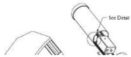
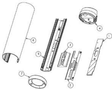
Exploded view diagram of a mechanical assembly with numbered parts for identification7 EXPLODED VIEW
7.1 Parts List
Ref Drawing
No. Number Part Description
I LTC 9480/20HTR 24VAC Heater Kit
2 315 3142 001 Camera B
3 315 3143 001 Foot Kit
6 315 3146 002 Rearcap Kit
7 315 2147 mm Rava Kir
WB-1, JB-1, PMA-1 Feed-through Mounts & Accessories
Instructions for Use

natural_image
Technical line drawing of three U-shaped pipe fittings with mounting brackets (no text or symbols)SAFETY PRECAUTIONS

The exclamation point within an equilateral triangle is intended to alert the user to presence of important operating and maintenance (servicing) instructions in the literature accompanying the appliance.
SECURITE
Unpack carefully. This is mechanical equipment and should be handled with care.
Check for the following items:
Verify the unit model number.
Instructions for Use.
If an item appears to have been damaged in shipment, replace it properly in its carton and notify the shipper. If any items are missing, contact the company from which the unit was purchased.
The shipping carton is the safest container in which the unit may be transported. Save it for possible future use.

WARNING: All mounts are designed to support a load only in a vertical direction. Mounts MUST be positioned as shown under SPECIFICATIONS.

Cautions:
a. For a secure installation, use four 8-mm (5/16-in) diameter fasteners (not included). Use stainless steel or zinc plated fasteners.
b. If bolts are used, they should extend through the mounting surface and be secured with flat washers, lock washers, and nuts on the opposite side. Each bolt must have a minimum pull-out strength of 200 kg (450 lb).
c. If studs are used, they should be anchored in concrete or welded to a steel backer plate. Each stud must have a minimum pull out strength of 200 kg (450 lb).
d. If the wall mount is attached to wood or to a blind structure (with no access to the rear), each fastener must have a minimum pull-out strength of at least 200 kg (450 lb).
-
Locate the four holes or stud locations using the flange as a template (four holes equally spaced on a 69.9-mm (2-3/4-in bolt circle).
-
Feed wires through the large hole in the flange or through the slot on the surface where the camera housing mounts.
-
Install the mount using bolts or studs at least 8-mm (5/16-in) in diameter.
-
To mount the camera or camera housing:
a. Mount camera with a 1/4-20 bolt and lock washer (not
furnished) in the center hole of the adjustable head.
b. Mount housings with three 1/4-20 bolts and lock washers (not furnished).
c. Lock mount head in position by using the supplied 1/8-inch long-arm hex wrench to tighten screws.
4.2 PMA-1 Pole mount Adapter
1. Tools required
8mm Hex Wrench
Banding Tool (PMA-I recommended)
- Secure the wall mount to the pole mount using the four (4) 8mm screws and lock washers provided. WB-I uses 8mm screws
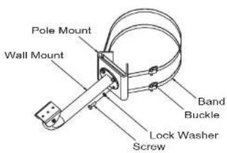
text_image
Pole Mount Wall Mount Band Buckle Lock Washer ScrewFigure 2: Securing Model PMA-I


text_image
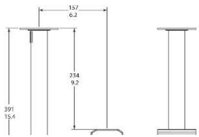
8.9 0.35 88.9 3.50 179.8 7.06 mm in 138.3 3.455 SPECIFICATION
5.1 WB1 18-cm (7-in) Indoor/Outdoor Feed-through Mount
Maximum Load: 9 kg (20 lb).
Mounting Head: Adjustable. 360° pan, 180° tilt.
Finish: Dark mushroom.
Approx. Weight: 0.3 kg (0.7 lb).
WARNING: All mounts must be mounted as shown.
WARNING: All mounts must be mounted as shown.
5.2 JB1 40-cm (15-in) Indoor/Outdoor Feed-through J-mount
Maximum Load: 9 kg (20 lb).
Mounting Head: Adjustable. 360° pan, 180° tilt.
Finish: Dark mushroom,
Approx. Weight: 0.5S kg (1.2 lb).
WARNING: All mounts must be mounted as shown.
E 2 DMA-1 pole Mount Adaples
WB-1 Feed-through Mount