
DR-8F45AT - Security Camera Ganz - Free user manual and instructions
Find the device manual for free DR-8F45AT Ganz in PDF.

| Product Type | 8-Channel HD DVR (Digital Video Recorder) |
| Video Input | AHD 2.0, HD-TVI (A and B), CVBS |
| Video Output (Main Monitor) | HDMI / VGA |
| Video Output (Spot) | Digital (HDMI or VGA) 1ch/4ch/9ch; CVBS 1ch/4ch |
| Audio Input | 8 channels (10KOhm, 2.8Vpp) |
| Audio Output | 1 channel (600Ohm, 2.8Vpp) |
| Audio Codec | G.711 |
| Video Compression | H.264 |
| Recording Rate | Max 240/200 FPS at 1080P, 720P, 960H, 4CIF, 2CIF, CIF |
| Motion Detection | Yes, with adjustable sensitivity and area setup |
| Alarm Input | 9 channels (8+1), pulled up to 5V via 10KOhm |
| Alarm Output | 4 channels relay (125VAC, 60VDC) plus 4 channels open collector |
| Internal Storage | Up to 5 SATA HDDs (internal) |
| External Storage | eSATA, NAS (FTP server for backup) |
| Network Interface | 1 x 10/100/1000 Mbps Ethernet (WAN) |
| USB Ports | 3 USB 2.0 ports (2 front, 1 rear) |
| RS-485 | 2 ports |
| RS-232 | 1 port |
| Remote Control | Included (IR remote) |
| Power Supply | DC 12V, 10A adapter (100-240VAC 50/60Hz input) |
| Cooling Fan | 2 x 80mm fans |
| Watchdog | Yes (auto reboot on system hang) |
| Web Viewer Support | Yes (Internet Explorer, Firefox, Chrome, Opera) |
| Mobile App | GanzView (iOS and Android) |
| Maintenance | Keep vents clear; clean with dry cloth; avoid liquids |
| Security | User login with password; group permissions; auto logout |
| Warranty | Refer to manufacturer; contact CBC or local distributor |
Frequently Asked Questions - DR-8F45AT Ganz
User questions about DR-8F45AT Ganz
0 question about this device. Answer the ones you know or ask your own.
Ask a new question about this device
Download the instructions for your Security Camera in PDF format for free! Find your manual DR-8F45AT - Ganz and take your electronic device back in hand. On this page are published all the documents necessary for the use of your device. DR-8F45AT by Ganz.
USER MANUAL DR-8F45AT Ganz
Before connecting, operating adjusting this product, read this instruction boolet carefully completely
MONITORING ARCHIVING
3 Start up / Shutdown 63 To start the Archive menu
5 Live Screen At a Glance
SYSTEM SETTING WEB VIEWER
12 To move to the System Setup menu 66 What is the Web Viewer?
13 Camera Setting 68 Live
18 Display Setting 72 Search
24 Audio Setup 74 Setup
25 User Setting
27 Network Setup
31 System Setting
37 Storage
41 Event Setup
RECORD SETTING MOBILE VIEWER
50 To start the Record Setup menu 86 GanzView
51 Record Setup
SEARCH ARCHIVE VIEWER
56 To move to the Search menu while 98 Getting started with the Backup Play in monitoring 99 Backup Player At a Glance
56 To move to the Search menu while in playback mode
PLAY APPENDIX
60 If you want to play 102 Specification
Start Up/ Shutdown
START
- Connect the adaptor to the 12VDC power input port in the rear panel of DVR.
√ Make connection when the power is not applied yet. - Connect AC cable to the power source. With a beep, the logo screen appears several seconds after the front LED turns on.
- When the booting process is completed, the live screen then the login screen appears.
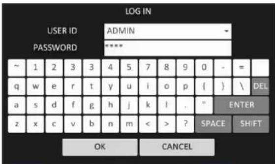
Log In
To manipulate or access the menus of DVR, you should have logged in.
- When the system starts, the login screen appears.
- Select a user and provide the password. The default password of the "ADMIN" account is "1234".
- Click
. If the login information is correct and valid, you will see the live screen.
√ For safe and secure use of the product, change the password after purchasing.
Log Out
To prevent unauthorized access, it is recommended to log out when you leave the screen.
√ Hover the cursor near the bottom of the screen to display the menu.
-
In the monitoring screen, click
-
While logged out, Search / Backup / System Setup / Record Setup / System Shutdown menus are restricted to use.

Monitoring
System Shutdown
-
In the monitoring screen, click
-
Use the virtual keyboard to enter the password.
-
Be sure to disconnect the power in the rear panel.

√ If you turn off the system in an abnormal manner such as removing the power cord while the system is in operation, the disk will have or increase the bad sectors, causing data loss and shortened life cycle of the disk.
Live Screen At a Glance
The live screen largely consists of three components: video window, status bar and timeline zone.

Video Window
Icons used in the video window.
| ITEM | Description | |
| Camera ID | CAM1 | Show the camera ID |
| Record Mode Icons | Displayed if an event recording is reserved. | |
| Display the status of the continuous recording. | ||
| Display the recording status when an alarm occurs. | ||
| Display the recording status when a motion event occurs.. | ||
| Display the status of the emergency recording.. | ||
| Audio Icon | The audio signal of the connected camera is outputting. | |
| Motion Detection Icon | A motion is detected by the connected camera. | |
Status Bar
Press the ▼ button on the remote control, or place the mouse in the lower area of the screen to display the status bar.
| ITEM | Description | |
| Menu Button |  | Select one of the system setup, search and backup menu items before accessing it. |
| User ID | ADMIN | Show the ID of the user who has currently logged in. |
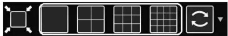
| Screen Control Buttons |  | Change the screen layout so that both status bar and timeline are displayed at all times. |
| Select a split mode. | ||
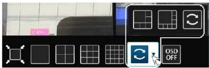
 | Select Auto Sequence or Special Split Mode. | |
| Display or hide the OSD menu on the screen. | ||
| PTZ |  | Move to the PTZ screen. You can control the PTZ operations of a PTZ-compliant camera on the PTZ screen. |
| Zoom |  | Move to the Digital Zoom. |
| Quick Log |  | Display the log list of the recent recording events. |
| Audio Channel Selection Button |  | You can use the camera supporting the audio input to listen to the audio. |
| Panic Record |  | Start the panic recording. |
| Alarm Indicator |  | Turns on if an event occurs. It does not turn on if no reaction to the event is yet defined.Click this to check the information of the event that occurred. |
| Network Connection Status |  | Check if network connection is made via an external PC or mobile device. Click this to view the details of the concurrent users and to check the network connection status. For more information, refer to "Network Setup". (page 27) |
| Disk Space |  | Show the disk space information. If you have set the disk overwrite mode, it will be displayed "OW" (Over Write) from the start point of the overwriting. Click this to view the details of the disk status.For more information, refer to "Record Setup". |
| Date & Time | 06-02-201404-55-18 | Display the current time and date. |
Timeline
Press the [▶] button on the remote control or move the cursor to the right of the screen to display the timeline. Double-click the timeline to move to the video screen. Drag and drop it to make backup or event search for the specified area.
| ITEM | Description | |
| Timeline Date |  | Display the date of the current timeline.Click this to select a desired date of the timeline. |
| Expand/Collapse the timeline |  | Expand or collapse the timeline. |
| Navigation through Timeline |  | Navigate through the timeline.You can also use the mouse wheel to do the navigation.. |
| Timeline Bar |  | Display the recording data with time. The color of each bar indicates the following:√ Green : Continuous Recording√ Red : Alarm Recording√ Blue : Motion Recording√ Yellow: Panic Recording |
Quick Menu.
| ITEM | Description |
| Channel No | Display the number of the current channel. |
| Play | Start playing the video of the selected channel from the specified time. |
| Zoom | Zoom the video of the selected channel. |
| Snapshot Capture | Capture the current live video and save it in the jpeg format.√ Then, you can save the captured image in the USB device. |
Using the status bar in the live mode
Selecting a split mode
Click a desired split mode from 1, 4, 9, 6, 8 and 16 split screen. Or press the [DISPLAY] button on the remote control until a desired split mode is displayed.
√ 4CH DVR model support only 1 and 4 split screen modes.
√ 8CH DVR model does not support 16 split screen modes.
natural_image
Pure electrical circuit lines without any symbolsAuto sequence
Click the Sequence button in the status bar, or press the [SEQ] button on the remote control to perform the specified sequence mode.
You can configure the sequence settings in
For details, refer to "Sequence". (page 20)
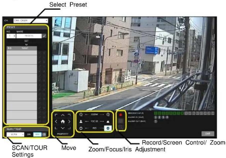
Controlling PTZ
You can control PTZ cameras connected to each channel. Use the mouse to click PTZ button on the status bar, or press the [PTZ] button of the remote control to initiate the predefined sequence.
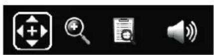
natural_image
Four black-and-white icons representing media and information symbols: folder, magnifying glass, document, and speaker (no text or labels)In PTZ mode, use buttons on the screen to control PTZ or use [ZOOM], [FOCUS] and [PRESET] buttons of the remote control.
Monitoring
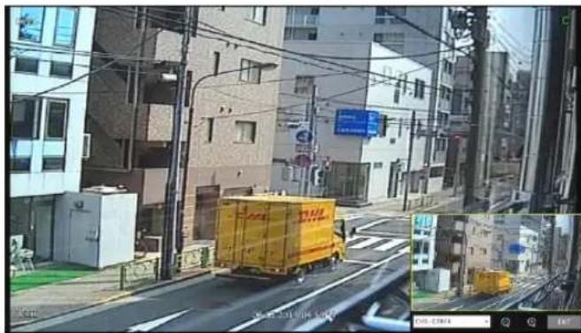
Digital Zooming
You can enlarge the monitoring screen for better view.
Zooming will enlarge the video of the selected channel. If no channel is selected, channel 1 will be zoomed.
- Click Zoom in the status bar or move the cursor to a desired channel and right-click it to display the context menu. Select
.
You can also press the [ZOOM] button on the remote control.
- Move to the zoom control screen. When the menu bar appears in the right bottom, use the buttons to control the zooming.
Select a channel to zoom in/out.
Zoom out the current (enlarged) image step by step.
Enlarge the current image step by step.
Zoom Box : Use the yellow box to move to or select a desired zooming area.
EXIT Exit the zooming screen and return to the live screen.
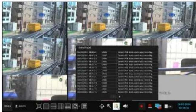
To check the event log
You can check the log of the events that occurred.
- Click Log to display the "EVENT LOG" window. The log list is sorted with the latest one on top.
- Double-click a desired log to display the event video. You will move to the play screen of the selected log.
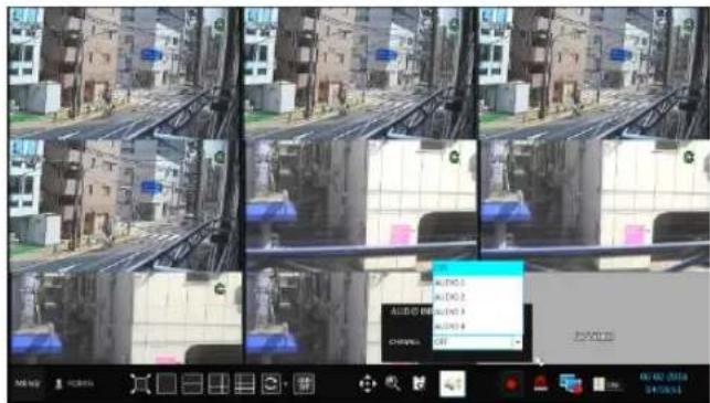
To select an audio input channel
Select a channel from which the audio signal will be received.
CHANNEL : Produces the selected channel's Audio, regardless of the split screen mode.
LINK TO FULL SCREEN :When switching the DVR display mode to view one channel, it Produces the selected channel's audio.
Monitoring
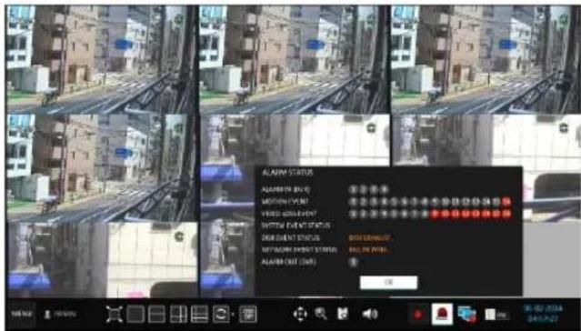
To check the alarm status
You can check the alarm status of each camera.
Click
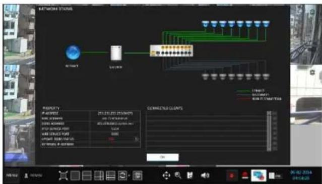
To check the network status
Shows connection status of camera and network devices.
Click to display detailed information on current users and network connection
Click
√ For more information, refer to "Network Status". (page 29).
flowchart
graph TD
    A["Start"] --> B["Connection"]
    B --> C["Terminal 1"]
    B --> D["Terminal 2"]
    B --> E["Terminal 3"]
    B --> F["Terminal 4"]
    B --> G["Terminal 5"]
    B --> H["Terminal 6"]
    B --> I["Terminal 7"]
    B --> J["Terminal 8"]
    B --> K["Terminal 9"]
    B --> L["Terminal 10"]
    style A fill:#f9f,stroke:#333
    style B fill:#ccf,stroke:#333
    style C fill:#cff,stroke:#333
    style D fill:#ffc,stroke:#333
    style E fill:#cfc,stroke:#333
    style F fill:#fcc,stroke:#333
    style G fill:#fcf,stroke:#333
    style H fill:#cff,stroke:#333
    style I fill:#ffc,stroke:#333
    style J fill:#cfc,stroke:#333
    style K fill:#fcc,stroke:#333
    style L fill:#ffc,stroke:#333
To check the disk status
You can check the storage space of the current disk and check also if there is any problem with the disk.
Click
√ For more information, refer to "Disk Information". (page 37)
Monitoring
Saving captured snapshots
You can capture the current video screen and save or export to a connected storage device.
- Select a channel first, and right click to open pop up menu, and select
menu item, or press the [SNAPSHOT] button of the remote control.
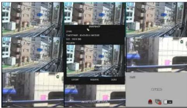
- Connect a storage device, and click
button. To save the captured image onto the built-in HDD, press the button.
√ Saved image can be found in the “Archive>Reserved data management” and can be backed up.

- Enter the
and and press or button
A progress bar appears and indicates the progress of exporting to storage device.
BURN : Snapshot is stored in the connected USB storage device.
ERASE & BURN : Deletes all files in the connected USB storage and then saves the snapshot.
√ Note that
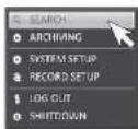
To move to the System Setup menu
How to use the mouse

flowchart
graph LR
    A["MENS"] --> B["SEARCH"]
    B --> C["ARCHIVING"]
    C --> D["SYSTEM SETUP"]
    D --> E["RECORD SETUP"]
    E --> F["LOG OUT"]
    E --> G["SHUTDOWN"]
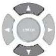
How to use the remote control 1
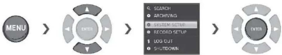
flowchart
graph LR
    A["MENU"] --> B["ENTER"]
    B --> C["SEARCH"]
    C --> D["ARCHIVING"]
    D --> E["SYSTEM SETUP"]
    E --> F["RECORD SETUP"]
    F --> G["LOG OUT"]
    G --> H["SHUTDOWN"]
    H --> I["ENTER"]
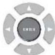
How to use the remote control 2

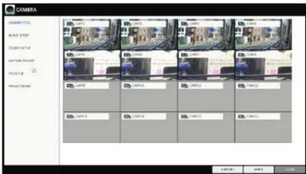
Camera Setting
You can configure the display settings of: camera title, covert option, motion and camera type
ANALOG TYPE SETUP
You can set the analog type of each camera channel.
-
From
- , select . -
Use the [▲▼◄►/ENTER] buttons on the remote control or use the mouse to set the type appropriate for the camera connected.
√ Not all types are compatible therefore check before connection the camera.
√ Select "AHD" for standard Analog camera
-
To apply the change, click
in the bottom of the screen. -
When done, press the [EXIT] button on the remote control or click
button. The confirmation message appears and you will return to the previous menu.

You can change the camera ID that is displayed on the screen.
-
From
- , select . -
Use the [▲▼◄►/ENTER] buttons on the remote control or use the mouse to select a channel that you want to rename.
Alternatively, simply double-click the camera to rename from the top left corner.
- Once the virtual keyboard appeared, select desired alphanumeric characters to complete your input, and press the
button.
√ The
-
To apply the change, click
in the bottom of the screen. -
When done, press the [EXIT] button on the remote control or click
button.
The confirmation message appears and you will return to the previous menu.
√ Camera title allows up to 16 letters, combining numbers and upper/lower case alphabets.
System Setting
Image Setup
You can adjust brightness, contrast, color and quality setting of each channel's camera.
- From
- , select . - Use the [▲▼◄►/ENTER] buttons on the remote control or use the mouse to set each option of the image menu.
- To apply your changes, click
button. - Once completed with setup, press [EXIT] button of the remote control or click
button on the bottom of the screen. A confirmation dialog appears and returns to the previous menu.
√ Press
Covert Setup
You can set to hide the camera video so that a specific user or user group cannot view.
Set a channel(s) that you want to hide from a specific user or user group.
- From
- , select . - Use the [▲▼◄►/ENTER] buttons on the remote control or use the mouse to select a covert channel(s) from a specific user group.
ADMIN, MANAGER, USER : Set them to
.
The selected channel will be hidden from the applicable user account.
LOGOUT : Set it to
. When the user logs out, the selected channel will not be displayed.
- Select display title on live view screen for covert channel either "COVERT" or "NO VIDEO" To activate this settings, user need to logoff then login DVR again.
- To apply the change, click
button. - When done, press the [EXIT] button on the remote control or click
button.
The confirmation message appears and you will return to the previous menu.
To change the covert settings from user group to user, move to the
System Setting
Motion Sensor
Set the motion sensor of the camera so that it can detect a motion event.
-
From
- , select . -
Use the [▲▼◄►/ENTER] buttons on the remote control or use the mouse to specify the use of each option item.
ACTIVATION : turn on or off the motion sensor.
MOTION MARK: Set it to.
The video window will display the motion mark if a motion is detected.
SENSITIVITY : Set the sensitivity level of the motion sensor to either Daytime or Nighttime.
EDIT AREA : Specify the motion detection area.
- To apply the change, click
button. - When done, press the [EXIT] button on the remote control or click
button. The confirmation message appears and you will return to the previous menu.
√ The motion detection sensitivity may differ depending on the characteristics of the connected camera or installation environment.
Motion Area Setup
From the motion setup window, click
- Click
to move to the motion area setup screen. - If using the remote control, press the [ENTER] button to mark the current position.
- Use the arrow buttons to move to a desired block and press [ENTER]. The area setup will begin. Then, use the arrow buttons to specify the area.
√ Alternatively, you can use the drag-and-drop method to specify or release the area using mouse.
- If you select the specified area again, it will be released.
- Press the [EXIT] button on the remote control or right-click any area to display the popup window as in the right picture.
System Setting
- While the popup window is displayed, select
to set the detection sensitivity.
CHANNEL : select a channel to set the motion Sensitivity.
SENSITIVITY : 1(Low) \~ 30(High) - The higher the number is, the more higher the sensitivity level becomes.
DAYTIME : Specify the time period that will be considered as daytime.
- DAYTIME : specify the
for the daytime. - NIGHTTIME : specify the
for the nighttime.
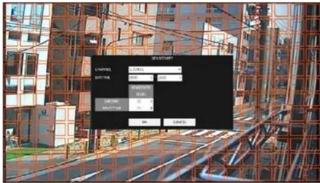
√ Images recorded in a low contrast scene such as at night cause severe noise, triggering the motion event too often.
√ If unwanted events occur frequently at night, you may want to reduce the motion sensitivity for the night duty.
PTZ Setup
You can configure PTZ cameras connected to each channel. Set the camera ID, protocol, baud rate and PTZ control speed for each channel.
-
From
- , select . -
Use the [▲▼◄►/ENTER] buttons on the remote or mouse to set protocol and baud rate.
√ Refer to user's manual of the PTZ the camera or consult camera installer for further details on PTZ settings, such as camera address, protocol and baud rate.
-
To apply your changes, click
button. -
Once the setup completed, press the [EXIT] button of the remote control or click
button on a confirmation dialog. Click to return to the previous menu.
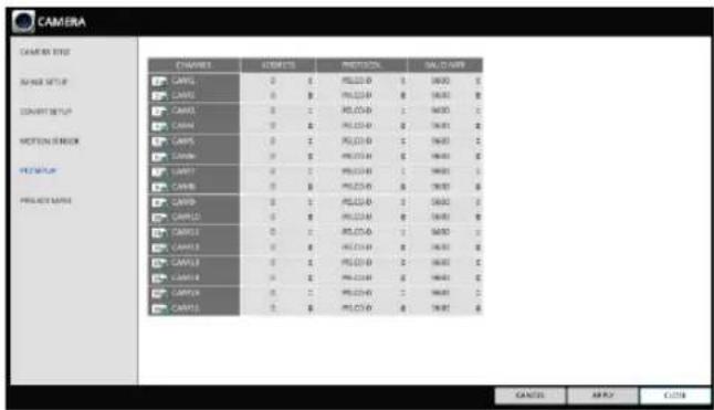
√ Select "COAXITRON" to enable CoC (Command over Coax) function.
System Setting
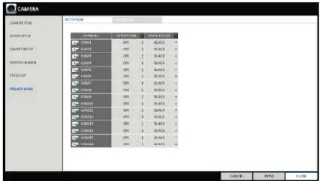
Privacy Mask
For privacy purposes, you can specify masking area for a selected camera's video.
-
From
- , select . -
Use the [▲▼◄►/ENTER] buttons on the remote or mouse to set channels enabled, mask color and its area.
ACTIVATION : Turn on or off the privacy mask. MASK COLOR : Select the color of the masked area, which will be displayed on the monitor.
-
To apply your changes, click
button. -
When done, press the [EXIT] button on the remote control or click
button.
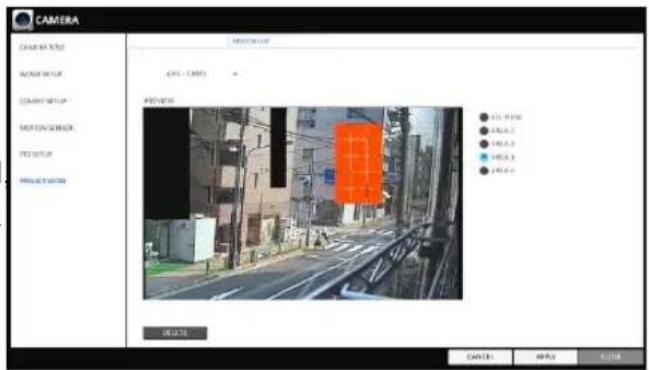
Privacy Mask Area Setup
You can specify privacy masking area.
- From tab on the right side.
- When using the remote, press the [Select] button to show the selector first.
-
Use direction key to move to the desired channel and the press the [Select] button to begin area setup.
Use direction keys to set the masking area. When using mouse, hold the mouse left button and drag to set or cancel the masking area. -
Selecting masked area again will exclude the corresponding block from the masking area.
Display Setting
You can configure the screen display setup for OSD, monitor, dual monitor, sequence, spot out, and POS/ATM (Available functions are depended on 1U/2U models).
OSD
You can set Camera Name, Icon, Status Bar, Timeline, Borderline, User Name and Language
-
From
- , select . -
Use the [▲▼◄►/ENTER] buttons on the remote control or use the mouse to set each option of the OSD item.
CAMERA TITLE : specify the display of the camera title on the screen.
RECORDING MODE ICON : specify the display of the record mode icon on the screen.
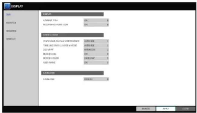
STATUS BAR ON FULL SCREEN MODE : select to show or hide the status bar in full screen mode.
- AUTO HIDE : place the cursor in the lower area of the screen to display the status bar. If moving the cursor up, the status bar will disappear.
- ALWAYS ON : The status bar will be displayed at all times.
- 5 SEC \~1 MIN : If no mouse movement is detected for from 5 seconds to 1 minute, the status bar will disappear.
TIMELINE ON FULL SCREEN MODE : select to show or hide the timeline in full screen mode.
- AUTO HIDE : place the cursor in the right corner to display the timeline. If moving the cursor to the left, the timeline will disappear.
- ALWAYS ON : The timeline will be displayed at all times.
- ALWAYS OFF : The timeline will not be displayed.
ZOOM PIP : Select to show or hide the Picture in Picture window on Digital Zoom.
-ALWAYS ON : PIP window will be displayed at all time.
-1/3/5 SEC : PIP window will disappear after selected time.
BORDER LINE : specify the display of the cross-border between channels in a split mode
BORDER COLOR : select a color for the border.
USER NAME : specify the display of the currently logged-in users on the status bar.
LANGUAGE : select a menu display language.
- To apply the change, click
button. - When done, press the [EXIT] button on the remote control or click
button.
The confirmation message appears and you will return to the previous menu.
System Setting
Monitor
If you change from monitoring mode to sequence, you will have to set the interval of the sequence.
-
From
- , select . -
Use the [▲▼◄►/ENTER] buttons on the remote control or use the mouse to set dwell for sequence mode and SPOT Out dwell.
SEQUENCE DWELL : Sets the time interval to the next screen mode for Live monitoring, which defines individual screen mode's dwell time in the Sequence. (Can set to 1 sec \~ 60 sec)
SPOT DWELL : Sets the time interval to the next view type, which defines individual view type's dwell time for SPOT OUT. (Can set to 1 \~ 60sec)
-
To apply the change, click
button. -
When done, press the [EXIT] button on the remote control or click
button. The confirmation message appears and you will return to the previous menu.
Dual Monitor
When using the Dual Monitor during surveillance, you can also set the screen mode, type, resolution and other settings.
If you change from monitoring mode to sequence, you will have to set the interval of the sequence.
-
From
- , select . -
Use the [▲▼◄►/ENTER] buttons on the remote control or use the mouse to set each item of the Dual Monitor.
DISPLAY MODE: When connecting two monitors, you can set the monitor management type. -DULICATE THESE DISPLAYS : The same screen will be displayed on each monitor at the same time. -MAIN MONITOR +SPOT : You can use one Monitor as the main monitor while using the Other as a SPOT output monitor.
DISPLAY TYPE: Select which monitor to use as the main surveillance and the SPOT output. If you selected SPOT output monitor, click
to add the view type. DISPLAY RESOLUTION: Set the resolution for each monitor.
-
To apply the change, click
button. -
When done, press the [EXIT] button on the remote control or click
button. The confirmation message appears and you will return to the previous menu.
Sequence
Select a split mode for the sequence, and also select a list of active items when the sequence is performed.
-
From
- , select . -
Use the [▲▼◄►/ENTER] buttons on the remote control or use the mouse to add a sequence or change the settings of the existing sequence.
ACTIVATION : Select a list that you want to activate the sequence for. Only one list will become active. ADD : add a sequence.

- To apply the change, click
button. - When done, press the [EXIT] button on the remote control or click
button. The confirmation message appears and you will return to the previous menu.
To add a sequence
- Click
in the bottom of the screen. - When the "ADD" dialog appears, enter a title using the virtual keyboard.
- Enter the name of the sequence and click
. -
When the
dialog appears, click . -
When the "SEQUENCE SETUP" dialog appears, select a split mode that you want to add from
. - If the selected split mode is displayed on
, select a channel you want
to display in each split screen.
- Click
.
The set sequence mode is confirmed and will be added to the Add Sequence list in order
- When done, click
in the bottom of the screen.
After the sequence type is saved, you will return to the previous screen.
- Place your mouse cursor over desired tile of added sequence, right Right-click on it or press the to edit or delete it.


[ENTER] button on the remote control
To edit a sequence
- Select a sequence that you want to edit in the list.
- The "EDIT" dialog appears.
- Use the [▲▼◄►/ENTER] buttons on the remote control or use the mouse to edit the selected sequence.
SEQUENCE TITLE : enter a new sequence name.
ACTIVATION : specify the use of the sequence.
MODIFY : change the settings of the sequence mode.
DELETE : delete the selected sequence list.
CANCEL : cancel the changes.
- Pressing the
button will display the Edit Sequence window. - To change the existing settings, select a screen mode that you want to edit and right-click to display the context menu. Then, select
. - When done, click
to close the window. - To apply your changes, click
.


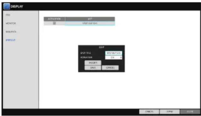
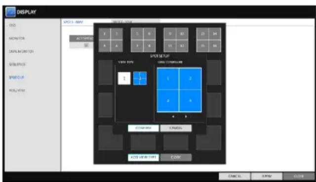
SPOT OUT
Apart from the main screen display, you can configure the Spot Out to display a Live channel as needed in various live view types. You can set the live view type of display output through the [SPOT] terminal and activate / deactivate it.
- From
- , select . - Use [▲▼◄►/ENTER] button of the remote control or mouse to edit Spot Out properties.
SPOT TITLE : Name the Spot Out setup.
ACTIVATION : Set whether to activate / deactivate the spot out setup.
MODIFY : Edit the view type of the spot output.
SAVE : Save the changes of spot output settings.
- To apply your changes, click
button. - Once completed with setup, press [EXIT] button of the remote control or click
button on the bottom of the screen. A confirmation dialog appears and returns to the previous menu.
To add a View Type to a SPOT OUT
- Select an item from the SPOT OUT list to be changed.
- The "MODIFY" window appears, click
button. - When the View Type selection window appears, click
button. - Select the desired View Type and configuration, and click
button. - Complete adding and click
to close the edit window.
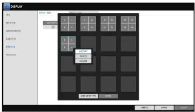
To edit or delete View type of the SPOT Out
- Select an item from the SPOT OUT list to be changed.
- The "MODIFY" window appears, click
button. - When the View Type selection window appears, select the desired View Type to be edited or deleted, and press [ENTER] button of the remote control or right click on it.
MODIFY : Displays "SPOT SETUP" window for editing View Type and other properties.
DELETE : Deletes the selected View Type.
- Complete editing and click
to close the edit window.
System Setting
POS/ATM
You can change the settings required to interlock the POS/ATM device connected to DVR.
-
From
- , select . -
Use [▲▼◄►/ENTER] button of the remote control or use the mouse to check POS/ATM settings.
DISPLAY MODE : You can select the screen where the data entered from POS/ATM are displayed.
-OFF : nothing is displayed on screen.
-BOTH: POS/ATM data are displayed on both LIVE and PLAYBACK screens.
-LIVE : The data are displayed on only LIVE screen.
-PLAYBACK : The data are displayed on only PLAYBACK screen.
POSITION : Select LEFT or RIGHT for the screen position.
FONT SIZE : Select SMALL, MEDIUM or LARGE for your desired font size.
√ The font size is applied to a single screen mode only.
FONT COLOR : Select WHITE, GLAY, YELLOW, BLUE, GREEN or RED for your desired font color
DWELL TIME : You can set how long the data is displayed on screen.
-UNTIL NEXT : Keep the data displayed on screen until the next data are input.
-1-60SEC : The data are displayed for the specified time.
SCROLL TYPE : Set the scroll type for screen.
-CLEAR : Display the data without scrolling.
-ROOL UP : Display the data with roll-up type scrolling.
HIGHLIGHT TEXT : Select whether to activate the highlighted text or not before entering the text and specifying its color.
EXCLUDE TEXT : Select whether to activate the excluded text or not before entering the text.
√ The POS data are displayed only in 1, 4, 6 and 8-split screen mode.
- To apply the changes, click
in the button of the screen. - When done, press the [EXIT] button on the remote control or click
in the screen. The confirmation message appears and you will return to the previous menu.
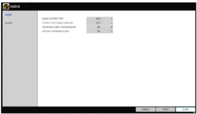
Audio Setup
Choose whether to receive the live sound source and select an audio channel.
- From
- - Use the [▲▼◄►/ENTER] buttons on the remote control or use the mouse to select an item that you want to edit.
AUDIO OUTPUT TYPE : You can select and use the conventional RCA audio output or the HDMI audio output.
DEFAULT LIVE AUDIO CHANNEL : select an Audio channel to monitor on the live screen.
NETWORK AUDIO TRANSMISSION : decide if DVR transfers the audio signal to the remote client. DVR → PC(Remote client)
RECEIVE NETWORK AUDIO : decide if DVR receives the audio signal from the remote client. PC(Remote client) → DVR
- To apply the change, click
button. - When done, press the [EXIT] button on the remote control or click
button. The confirmation message appears and you will return to the previous menu.
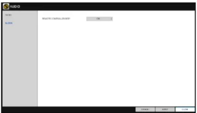
Buzzer output
You can set to output the buzzer if you manipulate the remote control.
- From
- -
Use the [▲▼◄►/ENTER] buttons on the remote control or use the mouse to select an item that you want to edit.
REMOTE CONTROL : specify the output of a beep when you press a button on the remote control.
-
To apply the change, click
button/ -
When done, press the [EXIT] button on the remote control or click
button. The confirmation message appears and you will return to the previous menu.
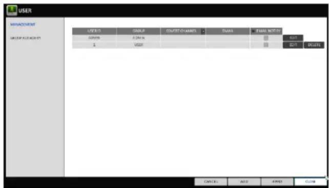
User Setting
You can configure the settings regarding user management and user and group permissions.
Management
You can add a user account(s) that can be edited at a later time.
- From
- , select . - Use the [▲▼◄►/ENTER] buttons on the remote control or use the mouse to add a user account or select an item that you want to edit.
- To apply the change, click
in the bottom of the screen. - When done, press the [EXIT] button on the remote control or click
in the lower screen.
The confirmation message appears and you will return to the previous menu.
To add a user account
- Click
in the bottom of the screen. - Use the [▲▼◀] buttons on the remote control and move to a desired item. Then, press [ENTER] to select the item.
USER ID : enter the user ID using the virtual keyboard.
PASSWORD : With the virtual keyboard, enter the password.
GROUP : From, and , select a group that the user belongs to.
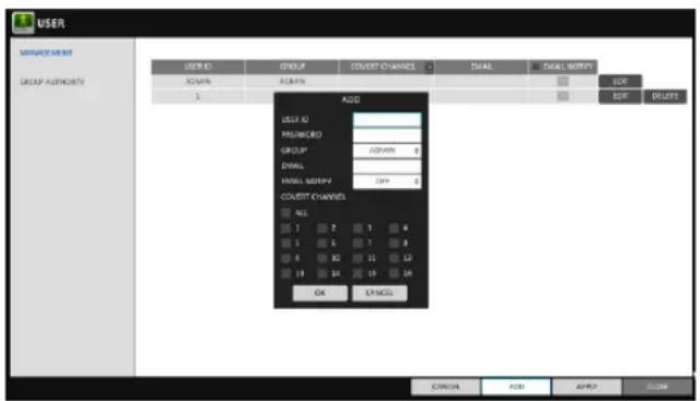
EMAIL : Type in the e-mail address to which you will receive notification of an event if it occurs.
EMAIL NOTIFY : Choose whether you will receive notification of an event if it occurs.
√ To use, a send mail server and its port should be configured previously.
COVERT CHANNEL : You can set the channel to hide from a specific user.
√ < COVERT CHANNEL >, option hides the video of the selected channel from being displayed on the screen.
- When done, click
. The added user account will be listed.
System Setting
To edit the user account information
- From the list of users, select a user account to edit and click
next to it. -
From the Edit window, make necessary changes and click
. -
To delete the user account, click
.
√ The
Group Authority
You can grant different user groups different permissions to a specific menu.
- From
- , select . - Use the [▲▼◄►/ENTER] buttons or use the mouse to set the permissions for both
SEARCH : Set the permissions for the Search menu.
ARCHIVING : Set the permissions for the Backup menu.
SYSTEM SETUP : Set the permissions for the System Setup menu.RECORD SETUP : Set the Access Permissions for the Record Setup menu.
EVENT ACTION CONTROL : Set the permissions to output the alarm or control the buzzer if an event such as alarm occurs.
LISTEN TO AUDIO : Set the permission to listen to the audio.
REMOTE LOG IN : Set the permission to access remotely.
SHUTDOWN : Set the permission to shut down DVR from the System menu.
√ The
- To apply the change, click
in the bottom of the screen. - When done, press the [EXIT] button on the remote control or click
button. The confirmation message appears and you will return to the previous menu.
Network Setup
You can set IP address, DDNS and E-mail settings, and check network status.
IP Setup
Specify the IP address as well as the remote service port.
- From
- , select . - Use the [▲▼◄►/ENTER] buttons on the remote control or use the mouse to specify each item of the network settings.
DHCP : If it is checked, set the IP address of the DVR to Dynamic IP.

√ For DHCP address allocation, the DVR should be connected to a network environment such as router that provides with DHCP server.
- Deselect DHCP option to enable manual static address configuration. service.
IP ADDRESS : Provide the IP address.
GATEWAY : provide the gateway address.
SUBNET MASK : provide the subnet mask address.
1ST DNS SERVER : Enter the address of the primary DNS server.
2ND DNS SERVER : Enter the address of the secondary DNS server.
RTSP SERVICE PORT : port number that the remote client receives the DVR video from.
WEB SERVER PORT : port number used for connecting to the DVR with the web browser.
PORT FORWARDING : If you are using a router, you can set the port forwarding so that external access to the DVR is enabled.
If the router does not support the uPnP protocol, you must set the port forwarding manually.
For more information, contact your network administrator.
DELETE PORT : release the port forwarding settings for the router.
MAX TX SPEED : Limit the network transfer rate to access a remote client.
The video signal may be transferred at a less rate than specified, which depends on the status of your network connection.
-
To apply the change, click
button. -
When done, press the [EXIT] button on the remote control or click
button.
The confirmation message appears and you will return to the previous menu.
System Setting
DDNS
You can configure the DDNS settings so that remote users who are connected to the network can access remotely.
√ DDNS is an IP redirection service in a dynamic IP environment that redirects (maps) the new IP address to a registered domain name each time the IP address is changed.
- From
- , select . - Use the [▲▼◄►/ENTER] buttons on the remote control or use the mouse to specify the use of DDNS and select a server.
DDNS : Specify the use of DDNS connection.
DDNS SERVER : Select a server to connect to.
DVR NAME : Enter the name of the DVR that you want to use as DDNS.
DDNS REGISTRATION TEST : Check if thecan be set as DDNS. If there is a duplicate name in the server, the registration will fail. If this is the case, rename the and press Test to check if it works properly. DVR ADDRESS : Provide the
and press the button. The name will be added automatically. DDNS CONNECTION TEST : Perform the connection test to check if DDNS is normally registered.
- To apply the change, click
in the bottom of the screen. - When done, press the [EXIT] button on the remote control or click
in the lower screen. The confirmation message appears and you will return to the previous menu.
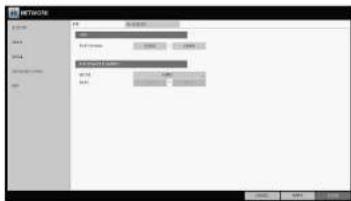
You can register and test an email address so that an email notification is delivered at a specific interval or if an event occurs.
-
From
- , select . -
Use the [▲▼◄►/ENTER] buttons on the remote control or use the mouse to specify the use of email and select a server.
SERVER : Set up the mail server. Set the mail Server that will be used for notification to the DVR. PORT : Enter the mail server port.
SECURITY : If it is set to
, the email will be transferred in secure mode. If it is set to , the email will be transferred to a server that does not support SSL. USER : Provide the email account (ID) of the sender.
System Setting
PASSWORD : Provide the password of the sender.
TEST EMAIL ADDRESS : Enter an email address for the test purpose.
TEST : Send a test email and check if the test email is delivered normally.
- To apply the change, click
in the bottom of the screen. - When done, press the [EXIT] button on the remote control or click
in the lower screen. The confirmation message appears and you will return to the previous menu.
Network Status
From the network map screen, you can check the internet connection status and camera connection status, and Check also the details of the connection status for each camera.
- From
- , select . - When done, press the [EXIT] button on the remote control or click
button. The confirmation message appears and you will return to the previous menu.
Network status
IP ADDRESS : Indicates the internal IP address of the DVR.
MAC ADDRESS: Indicates the internal MAC address of the DVR.
DDNS ADDRESS: Indicates the internal DDNS address of the DVR.
RTSP SERVICE PORT : Indicates the network port of the video service. For remote service, the router must have set up the port forwarding.
WEB SERVICE PORT : Indicates the web service network port. For the remote service to be enabled, the corresponding port of the router should have set up the port forwarding.
- DDNS UPDATE STATUS · Shows if the DDNS address was registered to the DDNS server
System Setting
RTP
1 From
2. Use the [▲▼↔/ENTER] buttons on the remote control or use the mouse to select one between
3. When done, press the [EXIT] button on the remote control or click
RTP
PORT RANGE: Set the range of port number for RTP UDP transfer, which will be dynamically allocated.
MODE: Set the port allocation method for "RTP Audio Back channel". Set tofor automatic allocation, or to to use specified port in the PORT Attribute.
√ RTP (Real-Time Transport Protocol) is a protocol designed to transport real-time data such as sound, video, etc. under unicast or multicast condition.
Multicast allows efficient network bandwidth utilization. If multiple clients are receiving monitoring video on a local area network.
Set the Multicast Address, Video/Audio Ports and TTL for each channel's Main/second Stream.
√ Note that the network must support multicast communication.
√ In general, multicast in WAN environment is not supported.

You can configure the settings of date/time, system management, and keyboard controller.
Date/Time
Specify the current date and time.
-
From
- , select . -
Use the [▲▼↔/ENTER] buttons on the remote control or use the mouse to change the time or set the options as necessary.
DATE/TIME : Set the current time and date. Click< > to adjust the time manually.
DATE FORMAT : specify the date format
TIME FORMAT : specify the time format.
TIME SERVER : obtain the current time from the time server. Click < > to get the current time.
AUTO TIME SYNC : automatically synchronize the time with the time server at a specific time.
SYNC AT : Set the time to sync with the time server.
TIMEZONE : specify the GMT standard time for your local area.
DST : You can set up or release the DST (Daylight Saving Time).
√ Both
-
To apply the change, click
in the bottom of the screen. -
When done, press the [EXIT] button on the remote control or click
in the lower screen. The confirmation message appears and you will return to the previous menu.
System Setting
System Management
You can check, update or reset the system information.
- From
- , select . - Use the [▲▼↔/ENTER] buttons on the remote control or use the mouse to set each option of the system management.
FW UPDATE : you can update the current software with the latest version.
FACTORY DEFAULT : Return the DVR settings to the factory default.
√ If you proceed with the firmware upgrade or select to reset to the factory default, all current settings of the DVR will be erased. In such a case, you must configure the network, time and recording settings again.

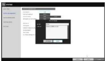
SYSTEM DATA : Save the system settings or get the system information from other device.
- SAVE : Store the DVR settings to a storage device. Connect the storage device to the USB port of DVR.
- LOAD : Apply the settings of the storage device to the DVR. Connect the storage device to the USB port of DVR.
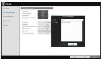
NETWORK SETUP WIZARD : Triggered when the correspondin button is pressed or upon factory initialization. The wizard guides through network configuration such as setting the DHCP or static IP address, WEB and RTSP service ports.

SYSTEM ID : Assign an ID to the DVR to distinguish it out from others when there are multiple DVR used.
√ The default value is "SYSTEM ID".
PASSWORD : Open or close the dialog box for settings of the menus: quit, system settings, record settings, backup, and search.
√ If it is set to
EXPIRED TERM OF PASSWORD : You will be prompted to change the current password after a certain period of time.
AUTO LOGOUT : If there is no user input for a certain period of time, you can set to log out automatically.
WAIT TIME : Specify the waiting time for Auto Logout. AC POWER FREQUENCY : Set 60Hz for NTSC signal, 50Hz for PAL signal
- When done, press the [EXIT] button on the remote control or click
in the lower screen to return to the previous menu.
System Setting
To perform the upgrade
- Connect the USB storage device that contains the updatable files.
- Click
. -
Select one(s) from the updatable files LIST listed in
. -
Click
. -
When the confirmation message appears, click
. -
The progress bar displays the progress of the firmware upgrade process.
-
When the upgrade is complete, reboot the system.
During the updating, never turn off the DVR forcibly or disconnect the USB storage device to avoid serious damage to the product or data.
System Setting
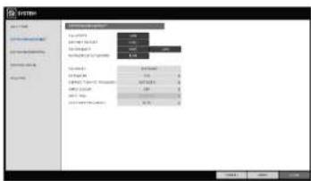
System Information
You can check the current system version and system-related settings.
- From
- , Select . - Check the status of the current system.
- When done, press the [EXIT] button on the remote control or click
button.
Control Device
Configure the settings of the remote control and keyboard controller.
- From
- , select . - Use the [▲▼↔/ENTER] buttons on the remote control or use the mouse to set the connection options for the control device.
SYSTEM ID : Set the ID of the DVR so that the keyboard controller can identify.
PROTOCOL : Set up the protocol of the keyboard controller.
BAUD RATE : Specify the RS485 communication speed.
REMOTE CONTROLLER ID : Set the ID of the remote control.
- To apply the change, click
in the bottom of the screen.
System Setting
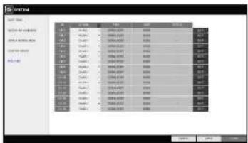
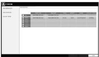
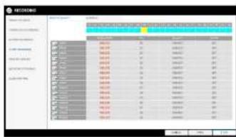
POS/ATM
You can check the configuration of the POS/ATM device connected to DVR.
-
From
- , select . -
Use [▲▼◄►/ENTER] on your remote control or use the mouse to check POS/ATM settings.
ACTION : Specify whether to activate the POS/ATM device or not.
TYPE : Display the type for each channel.
PORT : Display the port for each channel.
- Click
to change the POS/ATM settings.
- To apply the change, click
in the bottom of the screen. - When done, press the [EXIT] button on the remote control or click
in the lower screen.
To set the POS
- Press the
button to change in each channel. PORT : You can change the linked port by dropdown list.
√ The USB to serial device is required to add port.
PROTOCOL : GENERAL is designated for PROTOCOL by default.
BAUDRATE : Select the BAUDRATE between 2400-115200.
DATA BIT : You can select between 5 and 8 for DATA BIT.
CHARACTER SET : The ASCII CHARACTER SET is designated by default.
PARITY : You can select NONE. ODD or EVEN for PARITY BIT.
System Setting
Storage
You can configure the settings of and view information of the disk and external storage device.
2U model (DR-16F44-AT) supports both
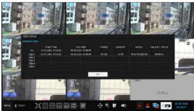
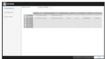
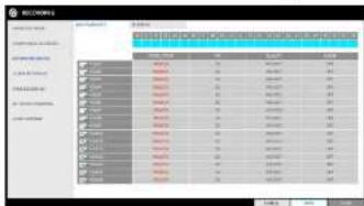
Disk Information
It will show information about the connected disk.
- From
- , select . - Use the [▲▼↔/ENTER] buttons on the remote control or use the mouse to check each connected peripherals.
START / END TIME : show the start time and end time of data stored in each disk.
STATUS : check if the connected disk is being used by the DVR. If you encounter a problem with the disk, the DVR will terminate the connection to the disk and mark it as 'Not In Use'.
CAPACITY : show the capacity of the disk.
MODEL : indicate the disk model.
S.M.A.R.T STATUS : Read the S.M.A.R.T information of the disk and check to display if the current disk is in normal operation.
- NORMAL : The disk is in a normal state.
- CHECK : The disk has an error so that you need to check the disk or the connection cables of the disk. If you leave the problem unresolved, no recording may be enabled. So it is recommended that you replace the disk immediately.
- ERROR : The disk fails or is unable to use due to an error of the disk or the cable. The disk should be replaced immediately. Contact the retailer or the customer service to replace the disk.
You can set to delete the recording automatically and set the overwrite options, and you can also format the HDD recording data.
- From
- , select . - Use the [▲▼↔/ENTER] buttons on the remote control or use the mouse to set the operation conditions of the disk.
DISK WRITE MODE
- If it is set to

- If the option is set to
and the HDD is full, the DVR will stop recording and output the beep or alarm that is pre-defined at . RECORDING TIME LIMIT : The recording data will be deleted after a specific time of reservation. If it is set to
, this function will be disabled.
DISK FORMAT : format the hard disk.
Note that formatting the HDD will delete all video data and logs.
- To apply the change, click
in the bottom of the screen. - When done, press the [EXIT] button on the remote control or click
button. The confirmation message appears and you will return to the previous menu.
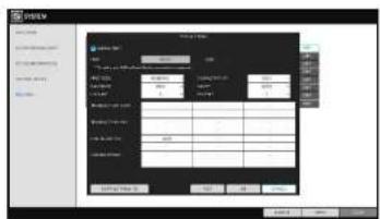
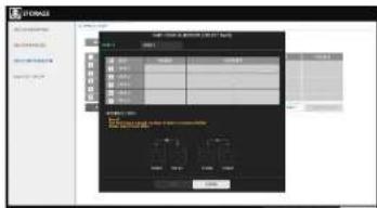
Disk Configuration
You can generate and configure a RAID array in your internal disks.
√ What is RAID?
RAID is a backup storage technology which allows you to use multiple independent disks as if they were just a single one.
RAID 1: The same duplicated data are also recorded in a different drive. That is the data
System Setting
- From
- , select . - Use the [▲▼↔/ENTER] on your remote control or use the mouse to change your DISK CONFIGURATION.
MODEL : Display the model name of each disk.
CAPACITY : Display the capacity of each disk.
STATUS : If any problem occurs in the disk where a RAID array has been configured, the disk is displayed as Degrade.REBUILD : Display whether to rebuild each disk or not.
REFRESH : Reload the status of the RAID array.
CREATE RAID : Press the button to create a RAID array.
-
To apply the change, click
in the bottom of the screen. -
When done, press the [EXIT] button on the remote control or click
in the lower screen. The confirmation message appears and you will return to the previous menu.
![mRNA 文件名(N): 类型(T): 大小(S): 100 位置(P): 0 备注: [ ] [ ] [ ] [ ] [ ] [ ] [ ] [ ] [ ] [ ] [ ] [ ] [ ] [ ] [ ] [ ] [ ] [ ] [ ] [ ] [ ] [ ]](/content/2026/06/1214963/images/711012ac92a8510e8c9f59144d4311842d244462e1a4398909fecee1203fffc1.jpg)
To configure a RAID array
- Press the
button on screen.
√ To configure RAID 1, at least 2 disks are required.
√ To configure RAID 5, at least 3 disks are required.
√ If you install deferent capacity of HDDs, smaller capacity will be configured for RAID.
System Setting
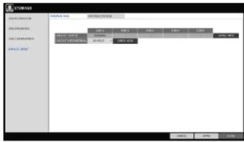
S.M.A.R.T settings
You can check the S.M.A.R.T information of the disk and specify the check frequency.
√ What is S.M.A.R.T information?
√ S.M.A.R.T (Self-Monitoring, Analysis and Report Technology) is to detect a HDD that is likely to cause a problem in the future with a warning message.
2U model (DR8/16FX5) supports both
- From
- , select . -
Use the [▲▼↔/ENTER] buttons on the remote control or use the mouse to check the S.M.A.R.T operation and specify the check interval.
S.M.A.R.T STATUS : Read the S.M.A.R.T information of the disk and check to display if the current disk is in normal operation. Click
to view the details. -
NORMAL : The disk is in a normal state.
- CHECK : The disk has an error so that you need to check the disk or the connection cables of the disk. If you leave the problem unresolved, no recording may be enabled.
So it is recommended that you replace the disk immediately.
- ERROR : The disk fails or is unable to use due to an error of the disk or the cable.
The disk should be replaced immediately.
Contact the retailer or the customer service to replace the disk.

Define various events, and specify the conditions to notify the user in various ways.
Alarm Out
Specify the alarm output conditions with the work schedule.
-
From
- , select . -
Use the [▲▼↔/ENTER] buttons on the remote control or use the mouse to select
and configure the related settings.
NAME : You can rename the alarm.
OPERATION : Set the alarm output mode.
- N/O (Normal Open) : It normally stays Open.
If an event occurs, it will switch to Close.
- N/C (Normal Close) : It normally stays Close.
If an event occurs, it will switch to Open.

DURATION : Specify the duration of the alarm output.
- TRANSPARENT : Keep the alarm out for as much time as the event lasts.
- UNTIL KEY : Keep the alarm out until a mouse or remote control button is pressed.
- 5 \~ 300 SEC : Keep the alarm out for as long as specified.
TEST : Forcibly output the alarm for the test purpose.
-
To apply the change, click
in the bottom of the screen. -
When done, press the [EXIT] button on the remote control or click
button. The confirmation message appears and you will return to the previous menu.
System Setting
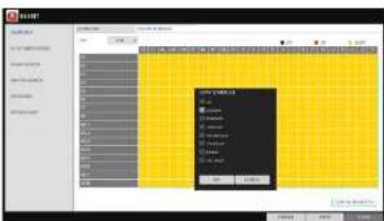
ON/OFF Schedule
You can activate or turn off the alarm output as scheduled.
- Use the [▲▼↔/ENTER] buttons on the remote control or use the mouse to select a
for the schedule. - Drag the mouse to resize the cell or use the on the [▲▼↔] buttons to move to the cell, then press [ENTER].
- Select a desired alarm output mode.
ON : The alarm output is always turned on.
OFF : The alarm output is always turned off.
EVENT : Trigger the alarm output in sync with the event.
- Click
to check the checkbox of the date that you want to copy the schedule at. - When done, click
to apply the settings. - To apply the change, click
button. - When done, press the [EXIT] button on the remote control or click
button. The confirmation message appears and you will return to the previous menu.

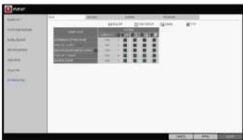
Event Notification
Specify the methods of notification such as buzzer, video popup or email if an event occurs.
- From
- , select . - Use the [▲▼◀] buttons on the remote control or use the mouse to select one from
, and .
System Setting
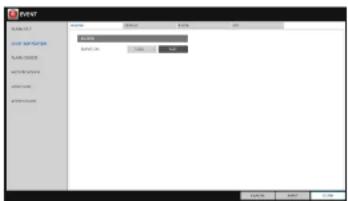
Buzzer output
You can notify the user of the event using the buzzer.
DURATION
- TRANSPARENT : Keep the buzzer out for as much time as the event lasts.
- UNTIL KEY : Keep the buzzer out until a mouse or remote control button is pressed.
- 5 \~ 300 SEC : Keep the buzzer out for as long as specified.
Display
If an event occurs, you can display the video screen or a popup message to notify the user.
VIDEO POPUP : Display the video channel that is synchronized with the event on a single split screen. Set the DURATION of the single split screen.
- TRANSPARENT : Keep the video popup displayed for as much time as the event lasts.
- UNTIL KEY : Keep the video popup displayed until a mouse or remote control button is pressed.
- 5 \~ 300 SEC : Keep the video popup displayed for as long as specified.
√ If multiple events occur at the same time, or if multiple event-related video channels exist, the video popup will be displayed in the maximum split screen mode rather than the single split screen mode.
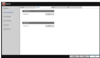
OSD POPUP : This will notify the user of the event with a popup message if an OSD popup event occurs. You can adjust the duration of the popup message.
- UNTIL KEY : Keep the OSD popup displayed until a mouse or remote control button is pressed. - 5 \~ 300 SEC : Keep the OSD popup displayed for as long as specified.
System Setting
If an event occurs, this will notify registered users of the event by email. If you do not want to receive the email, uncheck the
ADD NEW EMAIL
If you want to add a new mail recipient beside the existing ones, click this to add the recipient.
MINIMUM EMAIL FREQUENCY
Adjust the minimum frequency of sending the email. For example, even if you have set the frequency to one minute and another event occurs in less than one minute after the last email sending, the email for the new event will be sent one minute after.
Some email servers can block the email sending if the email delivery cycle is too short, and classify it as spam. Contact your email service provider to adjust the minimum delivery cycle so that the server does not classify the email as spam.
INCLUDE SNAPSHOT IMAGE: Set whether to include snapshot image of the event with the notification.
RECEIVING EMAIL SETUP : You can set your email to be sent at a specified time. You can select a specific time and day.
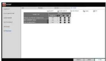
FTP
Upon events, uploads event notification onto the added FTP server.
FTP SERVER : Enter the FTP server address For event transfer.
DIRECTORY : Select or manually enter the destination folder of the FTP for event transfer.
FILE NAME : Select the uploading event file's format or manually set the file name.
MINIMUM FREQUENCY : Set the minimum recurrence delay for uploading event notification onto the FTP server.
System Setting
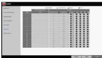
Alarm Sensor
You can configure the settings of the alarm sensor and specify the operation of the sensor if an event occurs. Number of alarm sensor depends on the model,
- From
- , select . - Use the [▲▼▶] buttons on the remote control or use the mouse to specify the sensor input method and operation.
NAME : You can specify the name of the alarm sensor.
OPERATION : You can specify the type of the alarm sensor.
- N/O (Normal Open) : Normally the sensor is left Open.
If the sensor switches to Close, an event will be triggered.
- N/C (Normal Close) : Normally the sensor is left Close. If the sensor switches to Open, an event will be triggered.
LINKED CAMERA : Set the camera to sync with the alarm sensor if it is triggered. If you have set the alarm recording and the sensor detects the recording, all synchronized cameras will start alarm recording.
ALARM OUTPUT (Available on 16 ch models) : Specify the alarm output channel if it is detected by the alarm sensor.
BUZZER : Specify the output of the buzzer if an alarm is detected by the alarm sensor.
VIDEO POPUP : Select to display the video popup if an alarm is detected by the alarm sensor. If there exist multiple, the video popup will be displayed in the maximum split mode.
OSD POPUP : Select to display the OSD popup message if it is detected by the alarm sensor.
EMAIL : Select to send an email if detected by the alarm sensor.
- ETD - Select whether to unload event notification onto the ETD upon detected alarm event

System Setting
Motion Sensor
You can set an action to execute when a motion is detected. For the settings of the motion sensor, move to
-
From
- , select . -
Use the [▲▼↔] buttons on the remote control or use the mouse to specify the ignorance interval and operation.
IGNORING INTERVAL : Specify the minimum interval of the motion event occurrence. For example, even if you have set the minimum frequency to 5 seconds and another motion event occurs in less than 5 seconds after the last motion event occurred, the new event will be ignored. If too many motion events occur, adjust to shorten the interval.
√ Motion recording will be triggered immediately after the motion occurred regardless of the above settings.
ALARM OUTPUT (Available on 16 ch models) : Specify the alarm output channel if a motion is detected by the motion sensor.
BUZZER : Specify the output of the buzzer if a motion is detected by the motion sensor.
VIDEO POPUP : Select to display the video popup if a motion is detected by the motion sensor.
EMAIL : Select to send an email if a motion is detected by the motion sensor.
FTP : Select whether to upload event notification onto the FTP upon detected motion event.
-
To apply the change, click
in the bottom of the screen. -
When done, press the [EXIT] button on the remote control or click
in the lower screen. The confirmation message appears and you will return to the previous menu.
Video Loss
You can specify a reaction to the case where no video is received from the camera.
- From
- , select
A. 11. 12. 13. 14. 15. 16. 17. 18. 19. 20. 21. 22. 23. 24. 25. 26. 27. 28. 29. 30. 31. 32. 33. 34. 35. 36. 37. 38. 39. 40. 41. 42. 43. 44. 45. 46. 47. 48. 49. 50. 51. 52. 53. 54. 55. 56. 57. 58. 59. 60. 61. 62. 63. 64. 65. 66. 67. 68. 69. 70. 71. 72. 73. 74. 75. 76. 77. 78. 79. 80. 81. 82. 83. 84. 85. 86. 87. 88. 89. 90. 91. 92. 93. 94. 95. 96. 97. 98. 99.
System Setting
POS/ATM
-
From
- , select -
Use the [▲▼▶] buttons on the remote control or use the mouse to specify event parameter and the reaction to event.
TEXT: Specify the text to detect POS/ATM event.
LINKED CAMERA :Select which camera(s) to Interlock when detecting POS/ATM events.
ALARM OUTPUT : Specify in which channel to output the alarm when detecting POS/ATM events
PRESET : Move camera based on the preset criteria when detecting POS/ATM events. BUSSER : Select whether to sound the buzzer when detecting POS/ATM events.
VIDOE POPUP: Select whether to pop up corresponding video when detection POS/ATM events. If there are multiple
, the video screen pops up with maximum split views. EMAIL : Select whether to send an email when detecting POS/ATM events.
FTP : Select whether to send the event to FTP server when detecting POS/ATM events.
-
To apply the change, click
in the bottom of the screen. -
When done, press the [EXIT] button on the remote control or click
in the lower screen. The confirmation message appears and you will return to the previous menu.
System Setting
System Event
You can set any action to an event related to the disk, recording, network or system. Like the other events, you may notify the event to the user using the alarm/buzzer output, OSD pop-up or email.
- From
- , select . - Use the [▲▼↔] buttons on the remote control or use the mouse to specify the reaction to each event.
- To apply the change, click
in the bottom of the screen. - When done, press the [EXIT] button on the remote control or click
in the lower screen. The confirmation message appears and you will return to the previous menu.
Disk
OVERWRITE START EVENT : if you set the disk write mode to
, this event occurs when the disk is full and the overwriting begins accordingly.
DISK FULL EVENT : if you set the disk write mode to, this event occurs when the disk is full (100%).
DISK SPACE EXHAUSTED EVENT : Event that is triggered if the disk is almost full. Click to specify the threshold percentage of usage to trigger the event.
S.M.A.R.T EVENT : Occurs if the disk causes the S.M.A.R.T error.
NO DISK EVENT : Occurs if no disk is recognized after the booting due to a disk failure or cable problem.
To detect the disk error, it is recommended not to change the settings of the S.M.A.R.T event, no disk event and buzzer output.
Record
System Setting
System
BOOTING EVENT: This event occurs when the DVR is booting.
LOGIN FAIL EVENT: This event occurs when the DVR fails to log in.
You can specify the times of clicking < ▼ > to trigger the event.
FAN FAIL EVENT: This event occurs if the CPU Cooling fan or unit's cooling fan does not work at all.
√ If the fan fails, no recording will proceed by the DVR. If you encounter a fan failure, contact the retailer or service center for technical assistance.
TEMPARATURE FAIL EVENT: This event occurs if the internal temperature of the DVR exceeds the effective range. Then, the DVR will not operate normally. If this is the case, check the followings and take a necessary measure.
-Check if the ventilation of the DVR is clogged with foreign substances. If so, remove them.
-Keep the DVR away from a heat source such as heater. Install it in flat, lower area with good
ventilation.
-If the problem persists, contact retailer of service center.
To monitor the normal operation of the DVR, it is recommended not to change the buzzer output settings of the fan failure event and the temperature fail event.
Network
TROUBLE IN INTERNET CONNECTION : Occurs if the Internet connection to the DVR fails. If you do not want to connect the DVR to the network, leave the
item blank. FAIL IN REMOTE LOGIN : This event occurs if a remote client fails to log in due to an invalid ID or password.
You can specify the times of clicking < ■ > to trigger the event.
FAIL IN DDNS UPDATE: This event occurs if the DVR tried to undate the DDNS address but failed
Record Setting
You can configure the record settings for the DVR. Only authorized users can access the Record Setup menu.
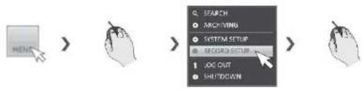
To start the Record Setup menu
How to use the mouse
flowchart
graph LR
    A["REDACT"] --> B["ARCHITORS"]
    B --> C["SYSTEM SETUP"]
    C --> D["RECORD SETUP"]
    D --> E["LOOK OUT"]
    D --> F["SHIFTDOWN"]
How to use the remote control 1

flowchart
graph LR
    A["MENU"] --> B["ENTER"]
    B --> C["ENTER"]
    C --> D["ENTER"]
Record Setting
Record Setup
Operation Mode
You can set the recording options for Auto or Manual mode.
- From
menu, select . - Use the [▲▼↔] buttons or use the mouse to set
to or . - Set the recording options for each selected Record mode.
- To apply the change, click
in the bottom of the screen. - When done, press the [EXIT] button on the remote control or click
.
Auto Configuration
If you choose your preferred record mode, the DVR will recommend you the optimized settings for the selected record mode.
CONTINUOUS RECORD : Recording will proceed in the best quality regardless of the
event at all times.
As this option will always make recording in the best quality, the recording period is the shortest compared to the other record modes.
MOTION RECORD : Recording will proceed only if a motion is detected.
ALARM RECORD : Recording will proceed only if an alarm event occurs.
MOTION/ALARM RECORD : Recording will proceed only if a motion is detected or an alarm event occurs.
INTENSIVE MOTION RECORD : Normally recording will be performed in a low quality. However, the quality will switch to high if a motion is detected.
INTENSIVE ALARM RECORD : Normally recording will be performed in a low quality. However, the quality will switch to high if an alarm event occurs.
INTENSIVE MOTION/ALARM RECORD : Normally recording will be performed in a low quality. However, the quality will switch to high if an alarm event occurs or a motion is detected.
√ Motion : Normally, it means movement of an object. However, it implies a change to the illumination in the content of the DVR (Ex) Vehicle lights/headlights) illumination change, etc.

Record Setting
Manual Configuration
You can set the manual recording and panic recording options.
MANUAL CONFIGURATION OPTIONS : You can configure the recording settings by the time, date, and channel.
- SCHEDULE MODE : Set the recording
schedule for a day (daily) or for a week (weekly).
- PRE RECORDING TIME : Set the pre-recording time.
- POST RECORDING TIME : Set the post-recording time.
PANIC RECORDING OPTIONS : Set the panic recording duration.
If it is set to
recording will continue until you turn it off manually.

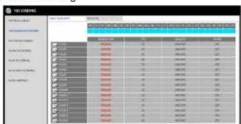
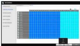
Continuous Recording
You can configure the settings of: continuous recording time, recording size, frame rate per second and quality.
- From the
menu, select .
√ From. you must set to before you can set the . - Use the [▲▼▶] buttons on the remote control or use the mouse to select either
or .
Size/FPS/Quality Setting
- Please select the day of the week to perform the continuous recording.
From
- Click a time cell from which you want to edit the SIZE/FPS/Quality and drag it to a desired cell. Or use the [▲▼▶] buttons on the remote control to move to the cell and press [ENTER].
Then use the [▲▼▶] buttons to move to a desired
- Select a start day of the week on the schedule.
- Click a time cell from which you want to make the schedule and drag it to a desired cell. Or use the [▲▼↔] buttons on the remote control to move to the cell and press [ENTER]. Then, use the [▲▼↔] buttons to move to a desired cell and press [ENTER] again.
-
When the time selection is complete, you will be prompted to specify the use of recording in the Record Setup window.
-
To apply the change, click
in the bottom of the screen. -
When done, press the [EXIT] button on the remote control or click
in the lower screen. The confirmation message appears and you will return to the previous menu.
Motion Recording
Specify the recording size of the motion event if it occurs and make schedule for that recording.
- From the
menu, select . - Use the [▲▼▶] buttons on the remote control or use the mouse to select either
or . - Set each item of
, , and use of the
√ For more information, see the "Continuous Recording". (page 52)
-
To apply the change, click
in the bottom of the screen. -
When done, press the [EXIT] button on the remote control or click
in the lower screen. The confirmation message appears and you will return to the previous menu.
Specify the recording size of the alarm event if it occurs and make schedule for that recording.
-
From the
menu, select . -
Use the [▲▼◀] buttons on the remote control or use the mouse to select either
or . -
Set each item of
, , and use of the
√ For more information, see the "Continuous Recording". (page 50)
-
To apply the change, click
in the bottom of the screen. -
When done, press the [EXIT] button on the remote control or click
in the lower screen. The confirmation message appears and you will return to the previous menu.
Panic Recording
In panic recording mode, you can specify the recording size and quality of the video.
-
From the
menu, select -
Set each item of
, , and use of the
√ For more information, see the "Continuous Recording". (page 52)

- To apply the change, click
in the bottom of the screen.
Record Setting
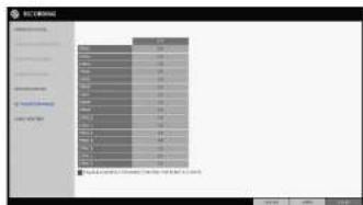
Network Streaming
You can specify the maximum FPS of network streaming for remote users.
√ Even if you set the FPS to high for the network streaming, the DVR will reduce the FPS according to the network status (Speed) before transferring the recording video.
-
From the
menu, select . -
Use the [▲▼↔] buttons on the remote control or use the mouse to select an item that you want to edit.
-
Set the
for each channel. -
When done, click
. -
To apply the change, click
in the bottom of the screen. -
When done, press the [EXIT] button on the remote control or click
in the lower screen. The confirmation message appears and you will return to the previous menu.
Audio Mapping
-
From the
menu, select -
Set the
-
To apply the change, click
in the bottom of the screen. -
When done, press the [EXIT] button on the remote control or click
in the lower screen. The confirmation message appears and you will return to the previous menu.

You can configure the record settings for the DVR. Only authorized users can access the Record Setup menu.
To move to the Search menu while in monitoring
How to use the mouse


How to use the remote control 1


How to use the remote control 2
SEARCH

To move to the Search menu while in playback mode
How to use the mouse
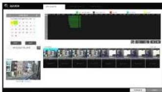
Search
Time Search
With the calendar, you can search for the recording data by the recorded date.
-
From the
menu, select -
Use the [▲▼◀] buttons or use the mouse to specify the search date and time from the calendar in the left corner of the screen.
FIRST : The first date of recording is automatically selected.
LAST : The last date of recording is automatically selected.
☐: Press this to display the time selection menu where you can specify the time and date.
- You can identify the type of the recording data by the color in the bar.
Yellow green (Pre-recording): The pre-recording is performed on the recording data after you set the
from. Green (Continuous) : The continuous recording is performed on the recording data.
Red (Alarm) : The alarm event recording is performed on the recording data.
Blue (Motion) : The motion event recording is performed on the recording data.
Yellow (Panic) : The panic manual recording is performed on the recording data.
- Click to move to a desired start time in the time bar, or use the buttons at the bottom of the status bar to make search.
: Recall the recording data.
: Expand the timeline of the time bar to a greater unit of time.
: Collapse the timeline of the time bar to a smaller unit of time..
▶ : Use this to move to a previous time that is hidden in the time hor as it is extended to a greater time unit

Search
Thumbnail Search
To improve your search, you will be provided with a list of thumbnails. Select Day, Hour or Minute to narrow down the search results.
-
From the
menu, select . -
Use the [▲▼▶] buttons or use the mouse to specify the search date and time from the calendar in the left corner of the thumbnail search screen.
FIRST : The first date of recording is automatically selected.
LAST : The last date of recording is automatically selected.
CHANNEL : Select a channel to search for.
DATE/TIME : Specify the search date and time.
√ The menus available differ depending on the selected interval mode.
INTERVAL: Select a time interval of the thumbnail view.
-
Double-click a desired play time in the recording data bar, or double-click a desired time image from the thumbnail list. You will move to the playback screen.
-
If you want to stop playing and return to the search screen, press [EXIT] or [SEARCH] on the remote control. You can also click
< "Minute" selection screen >
< "Hour" selection screen >
Search
Event Search
Search for events that occurred at the specified time and select an event to play from the list.
- From the
menu, select . - Use the [▲▼◇] buttons or use the mouse to specify the
and times in the left of the event search list. - Select a channel to search.
- Mark the checkbox of the event to search from The
list. - Press the
button.
The search results will be listed as shown.
TYPE : displays the event type.
TIME: displays the recording start time.
CONTENTS : shows the details of the event found.

ORDER BY : If you select
, the list will be sorted with the earliest one on top.
6. Double-click a desired event or clickin the lower right corner to move to the play screen.
7. If you want to stop playing and return to the search screen, press [EXIT] or [SEARCH] on the remote control. You can also click
Text-in Search
- From the
menu, select . - Use the [▲▼●] buttons or use the mouse to specify the
and times in the left of the event search list. - Select the channel box(es) for the channel(s) to search.
- Enter the keyword in
- to search for.
MATCH CASE: perform a case-sensitive search for the keyword entered.
MATCH WHOLE WORD ONLY: Perform an exact word search for the keyword entered.

Play
If you want to play
- To play the searched data
- You can search for and play a searched data.
- To play with the live viewer
- Simply double-click a desired time point in the right corner of the play screen.
√ If you move the cursor to the rightmost, the "Timeline" bar will be displayed.
- Select a desired channel in the live screen and right-click to select
Playback screen configuration
Video Window
Playback channel selection menu
Timeline
Menu / split-screen selection menu
Play Time
Play Bar
Video Window
Display the current video.
Timeline
Display the type of recording data
The vertical bar in the timeline indicates the current point of playback. Double-click a desired point in
Play
Playback channel selection menu
Description
Display the title of the selected channel.
Zoom the video of the selected channel.
(The zooming function is active only in '1'split screen.
The "Set bookmark" popup appears, and you can bookmark a play
point for the backup purpose
Capture the current video and save it in the jpeg format
Using the play bar
Description
Move forward or backward.
The video will be reversely played at the speed of x64 > 32 > 16 > 8 > 4 > 2 in this order.
Play the video in the reverse direction.
Stop playing forward or playback temporarily.
Play the video forward.
The video will be played forward at the speed of x2 < 4 < 8 < 16 < 32 <
64 in this order.
Move to the zoom in/out screen of the selected channel.
Capture the current video and save it in jpeg format
Then, you can save the captured video in the HDD or export it to an external USB memory device. While you perform the snapshot, the current video will be stopped playing.
Add a bookmark for the current playback screen. Press this to display the "SET BOOKMARK" window. Fill in all information required and click Start. The arrow in the bookmark button blinks to indicate that the bookmarking is in process. If you press the Bookmark button again, the bookmarking stops and the current settings will be reserved.
Then, the reserved data can be backed up in Archive menu or can be played in the "RESERVED DATA MANAGEMENT" menu.
Play
Bookmarking
During playback, you can add a bookmark for reserving the video data.
You can view the bookmarked data in the Archive menu, which can be saved to a connected device for the backup purpose.
- Provide a tag in the
item for data reservation. - Provide the details of the reserved data in the
input box. - Click
. You will return to the play screen with the backup progress. - To stop the bookmarking, click
- To quit the bookmarking, click
. To continue with bookmarking, just click . - Click
. You can export the reserved data to a connected storage device using the menu.
√ What is the
With the
This is useful if you want to backup data but you have no backup device available such as USB memory.
If you use "Reserve", the recording days will be compromised.
When you have backed up the reserved data to an external device, it is recommended to delete the internal reserved data.
Archiving
To start the Archive menu
Using the Archive menu during playback
- During the playback, click
- The "ARCHIVING SETUP" window appears where you can reserve the data.
- Click
menu. - Press the [ARCHIVE] button on the remote control.
Using the Archive menu during monitoring
- Click
menu. - Press the [ARCHIVE] button on the remote control.
Archive
You can archive the searched data or reserve it.
- From the
menu, select . - Select a date for the archive from the calendar in the left.
√ The date containing recording data will be marked in a colored box.
FIRST : The first date of recording is
automatically selected.
LAST: The last date of recording is automatically selected.
- Check the
and times.
√ Drag the timeline to specify the start and end time.
4. Mark the
- Click
. The results will be listed in .
√ The maximum backup capacity for one time is 20GB.
√ If the archiving request exceeds 20GB, the end
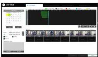
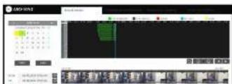
Archiving
Reserved data management
You can search for the reserved data and delete or import it to a storage device.
- From the
menu, select . The reserved data will be listed. - Select a data type form
and
AVI : Searches AVI video files stored in the DVR.
SNAPSHOT CAPTURE : Searches captured Snapshots stored in the DVR.
- If you want to play the data, double-click a desired data item or click it and select
. - If you want to import to a storage device, connect it to the DVR and click
. - If you want to delete the reserved data, click < > next to the list. Click
to cancel reserving the whole page at once. - To exit the Archive menu, click
.
Playing the archived data
You can search the storage device for the archived data and check the details of or play it.
- Connect the storage device containing the archived data.
-
When the storage device is recognized, click
. -
To view the details. click < > next to the list.
Archiving
Archive Devices Setup
Provide the FTP server information for archiving data in the HDD before testing the transfer.
- From the
menu, select - Move to the FTP information box.
- Fill in each item using a virtual keyboard.
HOST NAME : enter the address at which you can access the server.
PORT : enter the port number to which you can access the server.
USER NAME : enter the user ID with which you can access the server.
PASSWORD : enter the connection password.
DIRECTORY : specify the archiving path.

- When all information is filled, click
to check the connection status. - To apply the change, click
in the bottom of the screen. - When done, press the [EXIT] button on the remote control or click
in the lower screen. The confirmation message appears and you will return to the previous menu.
Web Viewer
What is the Web Viewer?
Web RA is a user-friendly software application that enables you to control the video data in connection with a remote DVR.
System Requirements
| The following is the minimum hardware and operating system requirements to run Web RA. | |
| Operating System | Windows Vista Home Baisc / PremiumWindow 7 or later |
| Web browsers: | Internet Explorer 9 or later/Mozilla Firefox 3.6/Google Chrome4.1/Opera 10Some web browsers other than Internet Explorer may not fully function |
| CPU | Intel Pentium 2.0 GHz or Higer |
| Memory | 512 MB |
| Display | 16-bit 1024 x 768 High Color |
| Hard Disk Drive | 50MB (space required for installing the web viewer)* Additional HDD space is required for saving your recordings.The file size of your recording may differ depending on the specified quality. |
Connection
Open a browser and enter the IP address of DVR, or type the URL in the address bar.
To connect to the DVR from inside
√ Check the "Network Status" and verify the
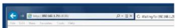
√ Enter the IP address and web service port in the address bar of the browser. Ex) http://192.168.1.116:8080/
To connect to the DVR from outside
Using the IP address
√ Check the "Network Status" and verify the
Web Viewer
- Provide the user ID and password.
√ The default User name : ADMIN; the default password is 1234.

- Click the warning bar to install the ActiveX.
√ If you fail to download the ActiveX control, move to Tools → Internet Options→Security→Custom Level →Download unsigned ActiveX control, and change its setting from "Disable (recommended)" to "Enable", and then click OK..
- Click
.

- When the installation is complete, you will see the live screen.
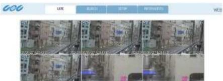
Item
Description
| 1.View selection tab | You can switch to the live, playback and setup screen and check the provided information. |
| 2. Live | Display the live screen of the currently connected DVR. |
| 3. Split Mode | Select and switch to a desired split-screen mode. |
| 4. Sequence | Set the sequence mode, switch to the next camera or select the full screen mode. |
| 5. Status Log | Show the connection status of each channel.Show the log. |
Web Viewer
Switching the split mode
Click the Switch button to switch the mode as follows:
<1-split Mode>
<4-split Mode>
<8-split Mode>
<9-split Mode>
Web Viewer
To save the video
- Click < : 同 > to start saving.
- The video from the selected channel will be saved to the PC in the AVI format. (Default path: C:\SaveFolder) Click < R > again to stop saving. Click
to display the context menu where you can change the saving path.
- Click < 📋 > to start printing.
- The current screen will be printed with the printer connected to the PC
Screen capture
- Click <
- The current screen of the selected channel will be saved to the path specified in the PC. (Default path: C::SaveFolder)
Click
to display the context menu where you can change the saving path.
ActiveX Settings
- Click < □>.
- When the setup screen appears, you can change the settings of the render type, audio, capture and saving path as well as the video streaming.
Render : DirectDraw is recommended in order to enable the hardware acceleration.
- If you want to change the saving path, click < □> (Save Folder) and specify a new path. The Windows Vista user cannot change the saving path.
- Change the streaming settings according to the PC specification and network environment. Auto mode is recommended.

Web Viewer
Status tab
Click

Log tab
Click

PTZ tab
Click
You can control the operations of a PTZ camera. Adjust the focus, zooming and iris of the camera. You can use the arrow buttons to control the operations of the camera.

Pattern : You can configure various settings of the camera including the zooming and movement.(Applied to some PTZ cameras only)
PRESET : Move the camera in a predefined direction.
Swing : The camera will move back and forth to a set position.
Web Viewer
Search
Click
Search Viewer at a Glance
Description
You can switch to the live, playback and setup screen and check the provided information.
Play the recording data.
Select and switch to a desired split-screen mode.
Set the sequence mode, switch to the next camera or select the full screen mode. You can turn on/off the voice signal.
Web Viewer
Search by time
Use the timeline to search for the data recorded in the DVR.
-
Select a date that you want to search.
-
Click
. -
Check the existence of recording data in the bottom time line and specify the time range for your search.
You can specify the start time by moving the time bar.
- Click
REFRESH : If your changes are not applied to the current screen, reload the changes.
PLAY : Play the searched video.
Backup : Archive the recorded video.
Search by event
You can sort the recording data items by event to facilitate your search.
-
Mark the checkbox of the event that you want to search for.
-
Specify the start and end dates and times for your log search.
-
Set the display order of the items found.
LATEST : The most recent event will be listed on top.
OLDEST : The earliest event will be listed on top.
-
Click
. You can check the log for your search at the bottom of the screen. -
Select a log to play the recording data.
Text-in Search
You can search for the recorded data in DVR by text.
- Enter your desired text to search for in ITEM
Web Viewer
Setup
Click
When done, click
] If the DVR is in process of system or record setting, the remote control will be disabled.
If you change the settings remotely at will, the major 'Record Settings' of the DVR may be changed, which is not recommended at all.
Setup Viewer at a Glance
Camera
Camera Title
You can name the camera title that is displayed on each channel screen. Select a channel to name and
provide a new title. Then, click
☐ You can enter up to 8 alphanumeric characters for the camera title.
Web Viewer
Covert Setup
You can set to hide the video of a specific camera from a specific user. Set to hide the camera video so that a specific user or user group can not view. To change the covert settings from user group to user, move to the
When done, click
Motion Setting
Specify the use of motion detection and reaction for each channel and set also the daytime/nighttime options.
Select a channel. Set the Motion detection zone and specify the daytime range.
When done, click
√ For information about how to set the motion area, refer to "Motion Sensor". (page 15)
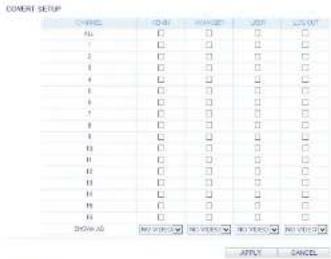
You can enable a camera channel's privacy masking function and set masking area.

Configure the settings for the time, title, boundary, icon and language that will be displayed on the screen. Make changes to each item of the OSD menu and click
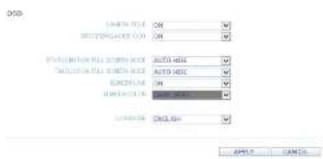
Audio
Audio / Buzzer
You can configure the settings of the voice and audio signal.

胡亿武
Web Viewer
User
User Management
You can add a user account and change the password.
√ For details about each displayed item,
refer to "User Setting". (page 25)
To add a user, click
information.
If you want to delete the user click next to it.
When done, click
Group Authority Setting
You can grant different user groups different
permissions to a specific menu.
Mark the checkboxes of the menu items accessible
by the user group.
When done, click
√ For more information about the accessible
menu items refer to "Group Authority".
(page 26)
Web Viewer
Network
IP Setup
You can check the network connection status and change the baud rate.
Change the maximum transfer rate and click
√ For more information about each network entry, refer to "IP Setup". (page 27)
正交AP
2017年1月1日
| F. M. (1) | 130 | 158 | 1 | 170 |
| M. (2) | 157 | 168 | 1 | 1 |
| M. (3) | 201 | 215 | 215 | 8 |
| M. (4) | 132 | 138 | 1 | 1 |
| M. (5) | 8 | 9 | 0 | 2 |
| HOT SERVICE PORT | 0514 | AUTO-PORT FORMARIDING | DELETE PORT |
| HOT SERVICE PORT | 0616 | AUTO-PORT FORMARIDING | DELETE PORT |
a)55.1 a)(c)
DDNS Setting
You can configure the DDNS settings so that remote users who are connected to the network can access remotely.
Change the DDNS settings and click
(1)
| TYPE | Cns |
| SCL-001402 | dutout.net |
| MUTCHN | 960 HDV/PROD 25 |
| OCTH | |
| OCTHCH | |
| OCTHCH | 960 HDV/PROD 20,dutout.net |
CANCE
Email Setting
You can register and test an email address so that an email notification is delivered at a specific interval or if an event occurs.
Provide the necessary information and click
[Unreadable]
√ For more information, refer to "Email". (page 28)
AFLY CANCE
RTP
For more information, refer to "RTP", (page 30)

Web Viewer
System
Date/Time Setting
Specify the current date and time.
When done, click
√ For For more information about each of the time and date settings, refer to "Date/Time". (page 31)
System Management
You can configure the access settings of: log in, log out, and auto logout.
System Information
You can check information of system firmware version, disk space, and network settings, as well as the status information of network connection and alarm I/O.
Web Viewer
Storage
Device Information
Internal storage devices physically installed in the DVR and their recording time information are displayed.
Check Disk operation mode
You can check disk operation mode setting.
S.M.A.R.T Status
The detailed S.M.A.R.T information of each internal storage device is displayed.
√ What is S.M.A.R.T?
This is a sort of HDD self-diagnosis tool that detects any error on the system and alerts the user if an error occurs.
Web Viewer
Event
Alarm Output
Specify the alarm output conditions with the work schedule..
When done, click
√ For more information about the alarm output and ON/OFF schedule, refer to "Alarm Out". (page 41)
Event Notification
Specify the notification method using one of
Specify the buzzer output time, display time and email notification, and click
√ For more information about the event notification, refer to "Event Notification". (page 42)
Web Viewer
Motion Sensor
You can set an action to execute when a motion is detected.
When done, click
√ For more information about how to set the motion sensor, refer to "Motion Sensor". (page 46)
Video Loss
You can select an action for
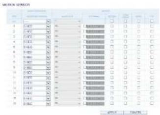

System Event
You can set which action to perform if an event related to the disk, recording, network or system happens.
You may want to notify the user of the event using the alarm output, buzzer, OSD popup and email.
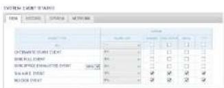

Web Viewer
Record Setup
Record Setting
You can set the recording options for Auto or Manual mode
When done, click
√ For more information about how to set each mode, refer to "Operation Mode". (page 51)
MANUAL CONSULTATION OPTIONS
| SCHEDULES | SINGLE |
| TYPE OF BETA (RUMBER) | SICC |
| NET TO BE TOLERABLE | BEANS |
PANC BED002450 OPTIONS
Collier Thef. 2010JAL
APPS CANCE
Continuous Recording
You can configure the settings of: continuous recording time, recording size, frame rate per second and quality. Click < ➤ next to each item to display the list of values available.
When you complete the recording size and schedule settings, click
√ For more information about the continuous recording size and schedule, refer to "Continuous Recording". (page 52)
(2) 基金运作规范
| TYPE | S | B | 12 | 19 | 26 |
| S | S | S | S | S | |
| M (mm) | L (mm) | T (m) | H (mm) | M (mm) | |
| CARW | Median 25 | 30 | 35 | ND 47877 | ND 47877 |
| CABB | Median 25 | 30 | 35 | ND 47877 | ND 47877 |
| CHBE | Median 25 | 30 | 35 | ND 47877 | ND 47877 |
| CKWD | Median 25 | 30 | 35 | ND 47877 | ND 47877 |
| CSWC | Median 25 | 30 | 35 | ND 47877 | ND 47877 |
| DARF | Median 25 | 30 | 35 | ND 47877 | ND 47877 |
| GALW | Median 25 | 30 | 35 | ND 47877 | ND 47877 |
| GASW | Median 25 | 30 | 35 | ND 47877 | ND 47877 |
| HANW | Median 25 | 30 | 35 | ND 47877 | ND 47877 |
| IMWR | Median 25 | 30 | 35 | ND 47877 | ND 47877 |
| LEMON | Median 25 | 30 | 35 | ND 47877 | ND 47877 |
| LEMON | Median 25 | 30 | 35 | ND 47877 | ND 47877 |
| LPGW | Median 25 | 30 | 35 | ND 47877 | ND 47877 |
| LPGW | Median 25 | 30 | 35 | ND 47877 | ND 47877 |
| LPGW | Median 25 | 30 | 35 | ND 47877 | ND 47877 |
| LPGW |
- 2014 - CACIL
Web Viewer
Motion Recording
Set the
Click < > next to each item to display the list of values available.
Complete setting the
√ For more information about the motion recording size and schedule, refer to "Motion Recording". (page 53)
Alarm Recording
Set the
Web Viewer
Panic Recording
From the
Click < 3 next to each item to display the list of values available.
When you have completed the manual record settings, click
√ For more information about the manual record settings, refer to "Panic Recording". (page 54)
| PARKING | ||||||
| DATE: 2016-09-05 | DATE: 2017-03-01 | DATE: 2017-04-01 | ||||
| L### | ### | ## | ## | ## | ## | ## |
| L### | ### | ## | ## | ## | ## | ## |
| L### | ### | ## | ## | ## | ## | ## |
| L### | ### | ## | ## | ## | ## | ## |
| L### | ### | ## | ## | ## | ## | ## |
| L### | ### | ## | ## | ## | ## | ## |
| L### | ### | ## | ## | ## | # | ## |
| L### | ### | ## | ## | ## | ## | ## |
| L### | ### | ## | ## | ## | ## | ## |
| L### | ### | ## | ## | ## | ## | ## |
| L### | ### | ## | ## | ## | ## | ## |
| L### | ### | ## | ## | ## | ## | ## |
| L### | ### | ## | ## | ### | ## | ## |
| L### | ### | ## | ## | ## | ## | ## |
| L### | ### | ## | ## | ## | ## | ## |
| L### | ### | ## | ## | ## | ## | ## |
| L### | ### | ## | ## | ## | ## | ## |

Network Streaming
You can specify the maximum resolution and FPS of network streaming for remote users.
Click <×next to each item to display the list of values available.
When done, click
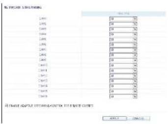
AUDIO MAPPING
Setting the Audio Mapping
You can activate audio of a channel to communicate remote user.
Click < > on the right side of each item to display audio channels available to select.
Click
You can use the smart viewer to monitor the network on a remote site and play the monitoring video anytime anywhere.
GanzView specification
Minimum/ recommended specification
| OS | Minimum specification | Recommended specification |
| Android Phone | Processor :800 MHz or higherFlash :512 MB or higherRAM :512 MB or higherSD Card :4 GB or higherOS :2.0 or higher | Processor :1 GHz or higherFlash :512 MBRAM :512 MBSD Card :16 GB or higherOS :2.1 or higher |
| iPhone | iPhone 3G,iPod touch 3rd GenerationiPhone OS 3.1.3 or higher | iPhone 3GS or higheriPhone OS 3.2 or higher |
Mobile Viewer
Using the GanzViewer on iPhone
How to download the iPhone-dedicated application
From your iPhone, access the App Store. Enter "GanzView" in the search bar to find it before downloading. Install the application on your iPhone. The GanzView supports the 1/4 split screen mode.
To connect to DVR with GanzView
- Select and run the GanzView.
- Click < □> in the top right corner of the DVR List to select and add a site to the list.

- Enter the server name and click
. - Provide the IP address, HTTP port number and RTSP port number, and click
.
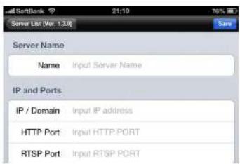
Mobile Viewer
- Provide the access ID of the DVR as well as the password.
- Specify the use of the Auto Login.
- Click
.

- Select the site that you added in the DVR List.

- Try to access the DVR. If connected successfully, you will see the screen as shown.
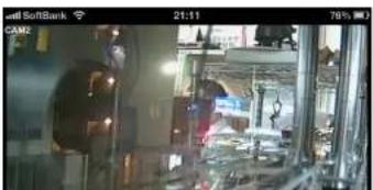
natural_image
Interior view of a modern industrial facility with machinery and workers (no visible text or symbols)Mobile Viewer
Split Mode
- Click any area on the screen. The main menu appears at the bottom of the screen.

- Click < □> in the top left corner to switch to 1-split mode; click < □> to switch to Multi-split mode. ✓ Swipe to scroll the screen to the left or right to move to the next camera video screen.

To use PTZ control
- Click < 📋 > in the top right corner.
- Use buttons on the screen for PTZ control. (available only for cameras supporting PTZ functions.)
- Click < > in the middle right corner.
- Click <+> for Zoom in, <-> for Zoom out
√ Touch the screen with two fingers and pinch open to zoom in, or pinch close to zoom out.
To View HQ (High Quality) Video
- Click < HOMO > in the right corner
- It switch to HQ video
Using the Log View
- From the main menu, click < img>. You can check the log of the data stored.

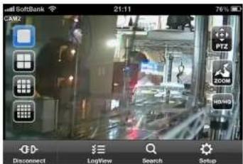

Mobile Viewer
Using the Search function
-
From the main menu, click < >. You can view the history of the data stored.
-
Select a desired time and date. You can use the vertical time bar to specify the start time.
-
Click <▶> to play the video recorded at the specified time.
-
Click any area to display the play bar with which you can control the playing direction and speed of the video.
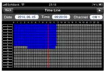
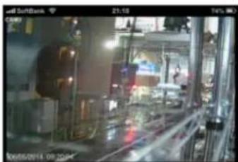
natural_image
Interior view of a factory or production line with machinery and workers (no visible text or symbols)
Mobile Viewer
Using the Setup function
From the main menu, click < Status >. You will be connected to the web viewer site.
√ For details about each displayed item, refer to "Setup". (page 74)
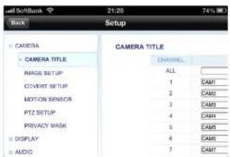
Mobile Viewer
Using GanzView with Android
How to download the Android-dedicated application
From your smart phone, access the Play Store. Enter "GanzView" in the search bar to find it before downloading. Install the application on your Smart Phone.
√ The GanzView supports the multi-split screen mode.
To connect to DVR with GanzView
- Select and run the GanzView.
-
Use the Add button to select and add a site to the list.
-
Please enter a Name.
-
Provide the IP address, HTTP port number and RTSP port number, and click
. -
Provide the access ID of the DVR as well as the password.
-
Select whether or not to save the ID and PW.
Mobile Viewer
- Select the site that you added in the DVR List. Press and hold the mouse button to display the pop-up window.
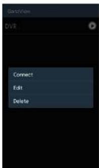
- Select
and try to access. If connected successfully, you will see the screen as shown.

natural_image
Interior view of a dimly lit industrial facility with machinery and workers (no visible text or symbols)Mobile Viewer
- Click < □> in the top left corner to switch to 1-split mode; click < □> to switch to Multi-split mode.
√ Swipe to scroll the screen to the left or right to move to the next camera video screen.
To use PTZ control
- Click < 📋 > in the top right corner.
- Use buttons on the screen for PTZ control. (available only for cameras supporting PTZ functions.)
: Adjust Focus
: Zoom In/Out
: Select one from the listed presets to run the selected preset action stored in the camera.
: Activates Pan / Tilt toward the selected direction.
: Captures the real-time video and saves as a still image in the handset_s image folder.
To use Digital Zoom
- Click < 📄 > in the middle right corner.
- Click < + > for Zoom in, < - > for Zoom out
√ Touch the screen with two fingers and pinch open to zoom in, or pinch close to zoom out.


Mobile Viewer
Using the Log View
-
From the main menu, click < .>. You can check the log of the data stored.
-
Select filter option from Alarm, Motion, Record, Etc. and click < Search >. You will view the log of related items.
Using the Search function
-
From the main menu, click
. You can view the history of the data stored.
-
Select a desired time and date. You can use the vertical time bar to specify the start time.
-
Click <▶> to play the video recorded at the specified time.
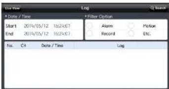
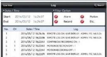
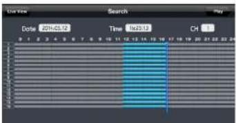

natural_image
Interior view of a laboratory or industrial facility with equipment and a person in safety gear (no visible text or symbols)Mobile Viewer
Using the Setup function
From the main menu, click < Save >. You will be connected to the web viewer site.
√ For details about each displayed item, refer to "Setup". (page 74)
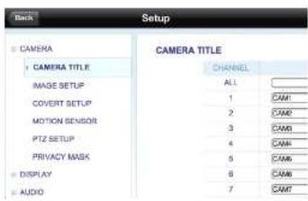
Archive Viewer
You can play the archived date w5th Backup player.
Getting started with the Backup Player
-
Connect the backup USB storage to your PC.
-
Open the folder saving the archived images.
-
Run the Backup Player.
-
Click <_0> in the bottom left corner to display the file browser. Select the archived file to play.
natural_image
Blank grid layout with no text, numbers, or symbols
Archive Viewer
Backup Player At a Glance

| Item | Description |
| 1.Setup | Configure the environment settings. |
| Minimize, Close | Minimize or close the Backup Player. |
| 2.Channel Information | Show the channel information and the video resolution. |
| 3.Play Time | Display the time of the current video image |
| 4.Play Time | Display the current playback time. |
Archive Viewer
Video Capture
Click <图标> to capture the current video image.
Selected Video : Capture the actual frame of the current video.
Screen : Capture the visible portion of the current video.
Format : Select a saving format. (BMP, JPG, PNG)
Path : Specify the saving path. -Default location : My Documents\My Pictures

Print Out
Click <→> to print out the image
When the "Print" window appears, check the preview and click

natural_image
Street view from a mobile phone showing buildings and electrical wires (no readable text or symbols)Archive Viewer
Settings
Click < to configure the Backup Player settings. You can check the version of the Backup Player.
√ Maintain image aspect ratio : Preserve the aspect ratio of the image. If you do not mark this option, the image will be adjusted to fit the screen.
√ About : You can check the program information including the current version.
Appendix
Specifications
| Item | DR-8F45AT | DR-16F45AT |
| VIDEO | ||
| INPUT SIGNAL | AHD 2.0, HD-TVI (A and B), CVBS | AHD 2.0, HD-TVI (A and B), CVBS |
| MAIN MONITOR | HDMI / VGA | HDMI / VGA |
| SPOT OUT | Digital(HDMI or VGA) 1ch/4ch/9ch | Digital(HDMI or VGA) 1ch/4ch/9ch/16ch |
| CVBS 1ch/4ch (1Vpp,75Ohm) x 1 | CVBS 1ch/4ch (1Vpp,75Ohm) x 2 | |
| LOOP THROUGH | NO | NO |
| MOTION DETECTION | YES | YES |
| AUDIO | ||
| INPUT SIGNAL | 8CH(10KOhm, 2.8Vpp) | 16CH(10KOhm, 2.8Vpp) |
| OUTPUT SIGNAL | 1CH(600Ohm, 2.8Vpp) | 1CH(600Ohm, 2.8Vpp) |
| CODEC | G.711 | G.711 |
| RECORDING | ||
| CODEC | H.264 | H.264 |
| REC.RATE | MAX. 240/200 FPS@1080P,720P,960H,4CIF,2CIF,CIF | MAX. 480/400 FPS@1080P,720P,960H,4CIF,2CIF,CIF |
| ALRM I/O | ||
| ALARM INPUT | 9CH (8ch+1ch),pulled up to 5V via 10KOhm | 18CH (16ch+2ch),pulled up to 5V via 10KOhm |
| ALARM OUTPUT | 4CH RELAY (125VAC,60VDC)4CH, O.C. Pulled up to 5V via 10KOhm | 8CH RELAY (125VAC,60VDC)8CH, O.C. Pulled up to 5V via 10KOhm |
| STORAGE | ||
| INTERNAL HDD (SATA) | 5 | 5 |
| EXTERNAL STORAGE | eSATA, NAS (FTP server for backup) | eSATA, NAS (FTP server for backup) |
| ODD | NO | NO |
| INTERFACES | ||
| USB(USB2.0) | 3 ports (2 Front + 1 Rear) | 3 ports (2 Front + 1 Rear) |
| RS-485 | 2 | 2 |
| RS-232 | 1 | 1 |
| LAN | 1(WAN) x 10/100/1000Mbps | 1(WAN) x 10/100/1000Mbps |
| REMOTE CONTROL | YES | YES |
| ETC | ||
| SIGNAL SWITCH | NO | NO |
| WATCHDOG | YES | YES |
| COOLINGFAN | 2 x 80mm | 2 x 80mm |
| POWER | ||
| POWER SUPPLY | DC12V Adaptor 10A,100-240VAC 50-60Hz | DC12V Adaptor 10A,100-240VAC 50-60Hz |
Appendix
Specifications
| Item | DR-16F44DAT |
| VIDEO | |
| INPUT SIGNAL | AHD 2.0, HD-TVI (A and B), CVBS |
| MAIN MONITOR | HDMI / VGA |
| SPOT OUT | Digital(HDMI or VGA) 1ch/4ch/9ch/16ch |
| CVBS 1ch/4ch (1Vpp,75Ohm) x 2 | |
| LOOP THROUGH | NO |
| MOTION DETECTION | YES |
| AUDIO | |
| INPUT SIGNAL | 16CH(10KOhm, 2.8Vpp) |
| OUTPUT SIGNAL | 1CH(600Ohm, 2.8Vpp) |
| CODEC | G.711 |
| RECORDING | |
| CODEC | H.264 |
| REC.RATE | MAX. 480/400 FPS@1080P,720P,960H,4CIF,2CIF,CIF |
| ALRM I/O | |
| ALARM INPUT | 18CH (16ch+2ch), pulled up to 5V via 10KOhm |
| ALARM OUTPUT | 8CH RELAY (125VAC,60VDC)8CH, Q.C. Pulled up to 5V via 10KOhm |
| STORAGE | |
| INTERNAL HDD (SATA) | 4 |
| EXTERNAL STORAGE | eSATA, NAS (FTP server for backup) |
| ODD | YES |
| INTERFACES | |
| USB(USB2.0) | 3 ports (2 Front + 1 Rear) |
| RS-485 | 2 |
| RS-232 | 1 |
| LAN | 1(WAN) x 10/100/1000Mbps |
| REMOTE CONTROL | YES |
| ETC | |
| SIGNAL SWITCH | NO |
| WATCHDOG | YES |
| COOLINGFAN | 2 x 80mm |
| POWER | |
| POWER SUPPLY | DC12V Adaptor 10A,100-240VAC 50-60Hz |

natural_image
Symbol of a trash bin crossed with diagonal lines, no text or labels presentEnglish
Disposal of your old appliance
- When this crossed-out wheeled bin symbol is attached to a product it means the product is covered by the European Directive 2012/19/EU.
- All electrical and electronic products should be disposed of separately from the municipal waste stream via designated collection facilities appointed by the government or the local authorities.
- The correct disposal of your old appliance will
Français/French
| CBC AMERICAS Corp. National HQ |
| 2000 Regency Parkway, Suite 600, Cary, NC 27518, U.S.A |
| http://www.computarganz.com/ |
| CBC AMERICAS Corp. Los Angeles Division |
| 21241 South Western Avenue, Suite #160 Torrance, CA 90501, U.S.A. |
| http://www.computarganz.com/ |
| CBC AMERICAS Corp.Mexico Branch Office |
| Galileo NO.20-101, Col. Polanco,Miguel Hidalgo, 11500, MEXICO |
| http://www.computarganz.com/ |
Europe
| CBC EUROPE GmbHDüsseldorfHansaallee 191,D-40549 Düsseldorf, GERMANY |
| http://www.cbc-europe.com/ |
| CBC EUROPE GmbH UK BranchLondon |
| Unit 9, Garrick Road Industrial Estate,Iving Way, London NW9 6AQ, U.K. |
| http://www.cbceurope.com/ |
| CBC EUROPE S.r.l. Milan |
| Via E. Majorana, 2 |
| 20834-Nova, Milanese (MB), ITALY |
| http://www.cboeurope.it/cctv |
| CBC(POLAND) Sp. z o.o.Warszawa |
| ul, Anny German 15,01-794, Warszawa, POLAND |
| http://www.cbcpoland.pl/ |
| CBC Co., Ltd. MOSCOW REP Office Moscow |
| Office 5038, Entrance #3, (Building 1) |
| World Trade Center, 12, Krasnopresnenskaya nab, Moscow, 123310, RUSSIA |
| http://www.cbc.ru/ |
Asia
| CBC. S Pte Ltd.Singapore#03-04 Thye Hong Center, 2 Lang Kee RdSingapore, Singapore 156086 SINGAPORE |
| http://www.cbcsingapore.com/ |
| CBC (THAILAND) Co., Ltd.Bangkok |
| 23 ^rd Floor, ITF Tower 2, 140/53-55,Sllom Road, Suriyawongse,Bangkok, Bangkok, 10500, THAILANDhttp://www.cbcthailand.com/ |
| CBC CORPORATION (INDIA) Pvt. Ltd.Mumbai |
| 2^nd Floor, B Wing, Marwah Centre,Krishanlal Marwah Marg,Andheri East, Mumbai 400 072, INDIA |
| PT. CBC PRIMA |
| Jakarta |
| MidPlaza □ Building 12 ^th Floor, |
| Jl. Jend. Sudirman Kav 10-11, |
| Jakarta Pusat, 10220 Republic of INDONESIA |
| T-CBC (TAIWAN) Co., Ltd.Taiwan |
| Room D, 10thFloor, No.305 Fushing N. Rd.,Taipei, 10579, Taiwan, R.O.C |
| http://www.t-cbc.com.tw/ |
China
| CBC (BEIJING) Trading Co., Ltd. |
| CBC (SHANGHAI) Trading Co., Ltd. |
| CBC (GUANGZHOU) Trading Co., Ltd. |
- MONITORING ARCHIVING
- SYSTEM SETTING WEB VIEWER
- RECORD SETTING MOBILE VIEWER
- SEARCH ARCHIVE VIEWER
- PLAY APPENDIX
- Start Up/ Shutdown
- START
- Log In
- Log Out
- Monitoring
- System Shutdown
- Live Screen At a Glance
- Video Window
- Status Bar
- Timeline
- Quick Menu.
- Using the status bar in the live mode
- Selecting a split mode
- Auto sequence
- Controlling PTZ
- Digital Zooming
- To check the event log
- To select an audio input channel
- To check the alarm status
- To check the network status
- To check the disk status
- Saving captured snapshots
- To move to the System Setup menu
- Camera Setting
- ANALOG TYPE SETUP
- System Setting
- Image Setup
- Covert Setup
- Motion Sensor
- Motion Area Setup
- PTZ Setup
- Privacy Mask
- Privacy Mask Area Setup
- Display Setting
- OSD
- Monitor
- Dual Monitor
- Sequence
- To add a sequence
- To edit a sequence
- SPOT OUT
- To add a View Type to a SPOT OUT
- To edit or delete View type of the SPOT Out
- POS/ATM
- Audio Setup
- Buzzer output
- User Setting
- Management
- To add a user account
- To edit the user account information
- Group Authority
- Network Setup
- IP Setup
- DDNS
- Network Status
- RTP
- Date/Time
- System Management
- To perform the upgrade
- System Information
- Control Device
- To set the POS
- Storage
- Disk Information
- Disk Configuration
- To configure a RAID array
- S.M.A.R.T settings
- Alarm Out
- ON/OFF Schedule
- Event Notification
- Display
- FTP
- Alarm Sensor
- Video Loss
- System Event
- Disk
- Record
- System
- Network
- Record Setting
- To start the Record Setup menu
- Record Setup
- Operation Mode
- Auto Configuration
- Manual Configuration
- Continuous Recording
- Size/FPS/Quality Setting
- Motion Recording
- Panic Recording
- Network Streaming
- Audio Mapping
- To move to the Search menu while in monitoring
- Search
- Time Search
- Thumbnail Search
- Event Search
- Text-in Search
- Play
- If you want to play
- Playback screen configuration
- Playback channel selection menu
- Description
- Using the play bar
- Bookmarking
- Archiving
- To start the Archive menu
- Using the Archive menu during playback
- Using the Archive menu during monitoring
- Archive
- Reserved data management
- Playing the archived data
- Archive Devices Setup
- Web Viewer
- What is the Web Viewer?
- Connection
- To connect to the DVR from inside
- To connect to the DVR from outside
- Using the IP address
- Switching the split mode
- To save the video
- Screen capture
- ActiveX Settings
- Status tab
- Log tab
- PTZ tab
- Search by time
- Search by event
- Setup
- Setup Viewer at a Glance
- Camera
- Motion Setting
- Audio
- Audio / Buzzer
- User
- User Management
- Group Authority Setting
- DDNS Setting
- Email Setting
- Date/Time Setting
- Device Information
- Check Disk operation mode
- S.M.A.R.T Status
- Event
- Alarm Output
- Alarm Recording
- Setting the Audio Mapping
- Mobile Viewer
- Using the GanzViewer on iPhone
- How to download the iPhone-dedicated application
- To connect to DVR with GanzView
- Split Mode
- To use PTZ control
- To View HQ (High Quality) Video
- Using the Log View
- Using the Search function
- Using the Setup function
- Using GanzView with Android
- How to download the Android-dedicated application
- To use Digital Zoom
- Archive Viewer
- Getting started with the Backup Player
- Video Capture
- Print Out
- Settings
- Appendix
- English
- Disposal of your old appliance
- Français/French
Brand : Ganz
Model : DR-8F45AT
Category : Security Camera