
HBT-C6POE-SP4 - Unspecified Avenview - Free user manual and instructions
Find the device manual for free HBT-C6POE-SP4 Avenview in PDF.

| Product Type | HDBaseT HDMI 1x4 CAT5/6/7 Splitter |
| Input | 1x HDMI, 1x 3.5mm IR IN, 1x LAN, 1x USB (Service only) |
| Output | 1x HDMI (Local), 1x 3.5mm IR OUT, 3x CAT5/6/7 (HDBaseT) |
| HDCP Compliance | HDCP 1.4 |
| Video Bandwidth | Single-link 340 MHz (10.2 Gbps) |
| Supported Resolutions | 480i/p, 720p, 1080i/p, 4K@30 (3840x2160@24/25/30Hz, 4096x2160@24Hz) |
| Audio Support | LPCM 7.1CH, Dolby TrueHD, Dolby Digital Plus, DTS-HD Master Audio |
| Transmission Distance (4K) | Up to 75m via CAT6e, up to 100m via CAT6a |
| Transmission Distance (1080p) | Up to 100m via CAT6e, up to 110m via CAT6a |
| Ethernet Pass-through | 100 Mbps (LAN port) |
| IR Control | Bi-directional, 30-50 kHz over CAT5/6 |
| PoE Support | Yes (Power over Cable to Receiver) |
| EDID Management | TV mode (default) or STD mode (1080p@60Hz, LPCM 2CH) |
| Power Supply | DC 24V 2.7A (locking adapter included) |
| Power Consumption | Approximately 65W (max) |
| ESD Protection | ±8 kV air, ±4 kV contact (Human Body Model) |
| Operating Temperature | 0°C to 50°C |
| Storage Temperature | -20°C to 60°C |
| Dimensions (Approx.) | 200 x 120 x 30 mm |
| Weight (Approx.) | 0.6 kg |
| Warranty | 3 years (parts and labor) |
| Safety Certifications | FCC Part 15, CE |
| Package Contents | 1x Transmitter, 1x Power Adapter, 1x Power Cord, 1x IR Receiver |
| Maintenance | Keep dry, avoid high temperature/humidity, use only supplied power adapter |
| Repairability | No user-serviceable parts; contact authorized service for repairs |
Frequently Asked Questions - HBT-C6POE-SP4 Avenview
User questions about HBT-C6POE-SP4 Avenview
0 question about this device. Answer the ones you know or ask your own.
Ask a new question about this device
Download the instructions for your Unspecified in PDF format for free! Find your manual HBT-C6POE-SP4 - Avenview and take your electronic device back in hand. On this page are published all the documents necessary for the use of your device. HBT-C6POE-SP4 by Avenview.
USER MANUAL HBT-C6POE-SP4 Avenview
IX4 CAT5/6/7 Splitter
with Bi-Directional IR/POE/Ethernet & Local Out
Product Application & Market Sectors

Corporate House

Vorship

Military Resident


Education Industri


Medical Aviation

TABLE OF CONTENTS
I. GETTING STARTED ....
I.1 IMPORTANT SAFEGUARDS....
1.2 SAFETY INSTRUCTIONS
1.3 REGULATORY NOTICES FEDERAL COMMUNICATIONS COMMISSION (FCC) 2
2. INTRODUCTION....3
2.1 PACKAGE CONTENTS 5
2.2 BEFORE INSTALLATION 6
2.3 CABLE SPECIFICATIONS....6
3. APPLICATION DIAGRAM....7
4. PANEL DESCRIPTION....8
INPUT PANEL (TRANSMITTER, HBT-C6POE-SP4) Front....8
INPUT PANEL (TRANSMITTER, HBT-C6POE-SP4) Rear....9
5. IR CABLE DEFINITIO....10
SECTION I: GETTING STARTED
I.1 IMPORTANT SAFEGUARDS
Please read all of these instructions carefully before you use the device. Save this manual for future reference.
What the warranty does not cover
• Any product, on which the serial number has been defaced, modified or removed.
• Damage, deterioration or malfunction resulting from:
- Accident, misuse, neglect, fire, water, lightning, or other acts of nature, unauthorized product modification, or failure to follow instructions supplied with the product.
• Repair or attempted repair by anyone not authorized by us.
• Any damage of the product due to shipment.
- Removal or installation of the product.
- Causes external to the product, such as electric power fluctuation or failure.
• Use of supplies or parts not meeting our specifications.
- Normal wear and tear.
• Any other causes which does not relate to a product defect.
- Removal, installation, and set-up service charges.
1.2 SAFETY INSTRUCTIONS
The HBT-C6POE-SP4, HDBaseT HDMI 1x4 CAT5/6/7 Splitter has been tested for conformance to safety regulations and requirements, and has been certified for international use. However, like all electronic equipments, the HBT-C6POE-SP4 should be used with care. Read the following safety instructions to protect yourself from possible injury and to minimize the risk of damage to the unit:
REGULATORY NOTICES FEDERAL COMMUNICATIONS COMMISSION (FCC)
This equipment has been tested and found to comply with Part 15 of the FCC rules. These limits are designed to provide reasonable protection against harmful interference in a residential installation.
Any changes or modifications made to this equipment may void the user's authority to operate this equipment.
Warning symbols Description

ONLY USE THE PROVIDED POWER CABLE OR POWER ADAPTER SUPPLIED. DO NOT TAMPER WITH THE ELECTRICAL PARTS. THIS MAY RESULT IN ELECTRICAL SHOCK OR BURN.

DO NOT TAMPER WITH THE UNIT. DOING SO WILL VOID THE WARRANTY AND CONTINUED USE OF THE PRODUCT.
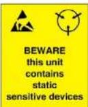
THE VIDEO BOARDS ARE VERY SENSITIVE TO STATIC. PLEASE ENSURE IF RACK MOUNTED OR INSTALLED ON A SURFACE, IT SHOULD BE IN A GROUNDED ENVIROMENT.
2. INTRODUCTION
The Avenview HBT-C6POE-SP4 HDBaseT 1x4 HDMI CAT5/6/7 Splitter with POE, Bi-Directional IR and Ethernet has been designed to extend High Definition video and multi-channel digital audio formats to (4) four Monitors.
Video Signals: 4K2K@30 (Ultra HD), 3D, Deep Color, and Full HD 1080p 48-bit color depth.
Audio signals: Lossless Multi-channel audio formats (DTS-HD Master Audio, Dolby TrueHD.
Data Signals: Bi-Directional IR signals 30 KHz to 50 KHz over CAT5/6.
The HBT-C6POE-SP4 includes (I) one unit: Transmitting unit (Tx) HBT-C6POE-SP4 with (3) Three UTP output ports and (I) HDMI output port which allows the user to extend video and audio via HDMI cable 35ft.
The bonus features with this device it can support PoE (Power over the CATx cable to the RX) also Internet (100Mbps Ethernet service when connected to a Router). These features has been added to this unit to give the installer and user a complete solution with the new trends in online streaming, network connected devices and new demand in Smart TV, Ultra HD monitors and content. The HBT-C6POE-SP4 allows bi-directional IR control of the source connected to the unit from the users IR remote control at the monitor side.
- INPUT: HDMI with 3D & 4Kx2K, 1080p, HDCP and DVI compliant source devices
- DATA RATE: From 250Mbps up to 3Gbps
- PC RESOLUTIONS: Up to VGA to WUXGA
- HD RESOLUTIONS: Up to 4Kx2K (3840x2160@30Hz and 4096x2160@24Hz)1080p (1920x1080@60Hz)
- AUDIO SUPPORTED: LPCM 7.1CH, Dolby TrueHD, Dolby Digital Plus and DTS-HD Master Audio
- AUDIO TRANSMISSION: (32-192kHz sample rate)
- DISTANCE: Up to 100 meters through CAT6e/6a/7 cables
- ETHERNET TRANSMISSION: Rate up to 100Mbps
- MODE: Standard 1080p@60Hz or TV EDID timing
- SERVICE: USB for Manufacturer USE ONLY
- 3D SUPPORT: Follow by Display / TV's EDID
The User has the ability to choose
HBT-C6POE-R -Full 5 play HDBaseT Receiver - Video/Audio/IR/RS232/Ethernet/POE over a single CAT5/6/7 up to 100m (330ft).

HBT-C6POE-RL - HDBaseT Lite Receiver - Video/Audio/IR/RS-232/POE over a single CAT5/6/7 up to 60m (200ft).
2.1 PACKAGE CONTENTS
| 1 | HBT-C6POE-SP4 ×1 | 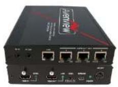 |
| 2 | LOCKING POWER ADAPTER/BRICK(+24V 2.7A DC) & POWER CORD FOR THE BRICK ×1 |  |
| IR RECEIVER ×1 | 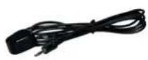 | |
2.2 BEFORE INSTALLATION
- Put the product in an even and stable location. If the product falls down or drops, it may cause an injury or malfunction.
- Don't place the product in too high temperature (over 50°C), too low temperature (under 0°C) or high humidity.
- Use the DC power adapter with correct specifications and supplied with the unit. If improper power supply is used the unit may malfunction and cause a fire.
- Do not twist or pull by force ends of the UTP cable. It can cause malfunction.
2.3 CABLE SPECIFICATIONS
| Cable Type Range Pixel clock rate Video Data Rate Supported Video | ||||
| CAT5e/6/7 100m <=225MHz <=5.3Gbps | (HD Video) | Up to 1080p, 60Hz, 36 bits, 3D (Data rates lower than 5.3 Gbps or below 225 Mhz TMDS clock). | ||
| CAT6A/7 | 100m | >225MHz | >5.3Gbps (Ultra HD Video) | 4K2K, 30Hz video formats |
| >5.3Gbps (Ultra HD Video) | 4K2K, 30Hz video formats | |||
3. APPLICATION DIAGRAM
HBT-C6POE-SP4
LAYOUT 1

4K2K (3840X2160) = 75m (165 feet) CAT6E 250MHz 4K2K (3840X2160) = 100m (330 feet) CAT6A 500-625MHz 1080p(1920x1080) = 100m (330 feet) CAT6E 250MHz 1080p(1920x1080) = 110m (360 feet) CAT6A 500-625MHz
CABLE INDEX
Input / Output
CAT 5E/6A/7
Internet / LAN
IR Signal
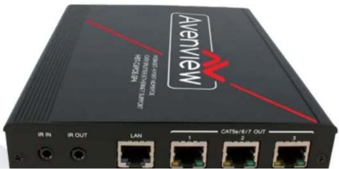
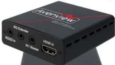
4. PANEL DESCRIPTION
INPUT PANEL (TRANSMITTER, HBT-C6POE-SP4) Front
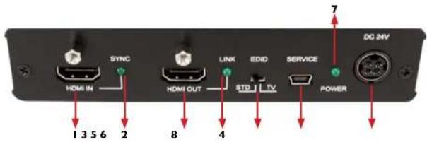
| 1. HDMI IN: To receive the source INPUT | 2. SYNC LED: Illuminates when HDMI Input port is connected to an active source. |
| 3. HDMI OUT: Connect to HDMI display Max 35ft via HDMI Cable or cascade with another Avenview type Transmitter. | 4. LINK LED: illuminates when HDMI output is connected to TV or display monitor |
| 5. EDID: Configure Mode (see Details below *) | 6. SERVICE: This connector is reserved for factory service only. |
| 7. POWER LED: Illuminates when power is connected. | 8. DC 24V: To power the unit via the 24V DC power supply (supplied) |
EDID TV: The default factory setting is TV; don't adjust if the image is displayed properly.
EDID STD: Switch to STD to use built-in EDID if the image is not displayed properly.
INPUT PANEL (TRANSMITTER, HBT-C6POE-SP4) Rear

| 9. IR IN: Use IR Extender in this port. 10. IR OUT: Use IR Master in this port | |
| 11. LAN: Connect to Internet service sharing rate of 100Mbps within the link of Transmitter.Warning: DO NOT connect this Port with any of the HDBaseT Receivers, this may trigger a power shot down and damage device. | 12. CAT5e/6/7 OUT 1~3: Connect these ports to CAT5e/6/7 HDMI Receivers (with or without PoE function) with CAT5e/6/7 cable to extend the signal up to 60m/100m |
5. IR CABLE DEFINITIO

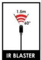
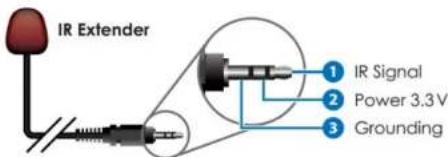
IR Sockets
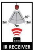
- IR BLASTER: plug in the IR blaster to the HBT-C6POE-SP4 to emit all IR command signals received from the IR Extender plugged into the Rx (Monitor Side) to control the devices corresponding to the IR signals. Example: Set Top Box or DVD player (The Source).
- IR EXTENDER: plug in the IR Extender into the (RX) Receiver (Monitor Side) to receive all IR command signals from the IR remote controls of the corresponding source. Example: Set Top Box or DVD player (IR Remote Control).
6. INSTALLATION (HBT-C6POE-SP4)
To setup Avenview HBT-C6POE-SP4 please follow these steps for connecting to a device:
I. Turn off all devices including monitors / TV
2. Connect to a HDMI source (such as a Blu-Ray Disc player) to the Transmitter HBT-C6POE-SP4
3. Connect HBT-C6POE-R 100m or HBT-C6POE-RL 60m with a CAT5/6/7 cable with shielded ends, then connect to display with HDMI cable.
4. Plug in 24V 2.7A DC Power (supplied).
5. Plug in the IR BLASTER: into IR out and the blinker on the IR eye (Source)
6. Plug in the IR Extender to IR IN to receive IR Signals from Remote
7. Power on the HDMI display
8. Power on HDMI Sources.
Notice
- Additional info on Guidelines to Test & Troubleshoot HDBaseT Systems
- Can be retrieved from our website under the category Downloads for this product HBT-C6POE-SP4
7. GENERAL TROUBLESHOOTING
| PROBLEM POSSIBLE SOLUTION | |
| NO IMAGE | Check if connection to the source and the display are correct.Ensure that display device supports 480p, 720p and 1080p 4K@30 resolutionTerminated to 568B standard with Shielded Ends RecommendedHigh Quality CAT5/6/7 Cable helps signal transmissionPlease use the supplied power supply-DC 24V 2.7ACheck LED Link light see (Section 3 Panel Description)Check LED Sync light see (Section 3 Panel Description |
| EDID ISSUE | EDID MODE-TV: The default factory setting is on TV. The unit will detect the 1st CAT5e/6/7 output's EDID. When obtained a (4K2K) Ultra HD 3840x2160 EDID the signal is transmitted.If the 1st CAT5e/6/7 output is without a Ultra HD 3840x2160 EDID the unit will detect all output's EDID and Transmit the signal that all outputs can accept.EDID MODE-STD: Switch to STD to use built-in EDID if the display has No Image. STD EDID's video at 1080p@60Hz and audio at LPCM 2CH. |
| SET-TOP BOXNO PICTURE | HDBaseT and HDMI 1.3 standards support CLOCK STRETCHING for i2buss protocolExample set top boxes like Scientific Atlantic results no picture. This can be resolved by swapping out the box for a newer version that supports HDMI 1.3 not HDMI 1.2 |
| Ensure the UTP cable is run within the wall away from EMI and High Voltage power Lines.Please check manual of device to ensure proper placement of IR Blaster on IR | |
8. SPECIFICATIONS
| Item Description | |
| UNITS HBT-C6POE-SP4 | |
| UNIT DESCRIPTION HDBaseT HDMI | 11 Transmitter |
| HDMI COMPLIANCE YES HDBaseT | |
| HDCP | Yes 1.4 |
| VIDEO BANDWIDTH Single-link 340 MHz [10.2Gbps] | |
| SUPPORTED RESOLUTIONS | 480i / 480p / 720p / 1080i / 1080p60 /4K@30 Up to Ultra HD (3840x2160@24/25/30Hz)4K2K-(4096x2160@24Hz) |
| HDMI INPUT/OUTPUT DISTANCE: | Up to 10m@1080p 8/12-bit |
| CAT5/6/7 CABLE | 4K2K: (3840X2160@30Hz) ~ 75meter (250feet) (CAT6e) /100meter (330feet) (CAT6a)FULL HD: (1080p) ~ 100meter (330feet) (CAT6e) /110meter (360feet) (CAT6a) |
| AUDIO SUPPORT LPCM 7.1CH, Dolby TrueHD, Dolby Digital Plus and DTS-HD Master Audio | |
| INPUT TMDS SIGNAL 1.2 Volts (peak-to-peak) | |
| INPUT DDC SIGNAL | 5 Volts (peak-to-peak, TTL) |
| ESD PROTECTION | Human body model — ± 8kV (air-gap discharge)& ± 4kV (contact discharge) |
| INPUT | 1x HDMI1x 3.5mm IR IN1x mini-USB Service only1x LAN port |
| OUTPUT | 1x HDMI Local OUT1x 3.5mm IR OUT |
Notice
- All HDMI over CATS transmission distances are measured using Belden CAT6A (625MHz), 4-Pair, U/UTP-Unshielded, Riser-CMR, Premise Horizontal Cable, 23 AWG Solid Bare Copper Conductors, Polyolefin Insulation, Patented Double-H spline, Ripcord, PVC Jacket using Quantum 980 signal HDMI Video Generator Module Video Pattern Testing.
-
- The transmission length is largely affected by the type of category cables, also the type of HDMI sources, and the type of HDMI display. The testing result shows solid UTP cables (usually in the form of 300m or 1000ft bulk cable) can transmit a lot longer signals than stranded UTP cables (usually in the form of patch cords). Shielded STP connectors are better suit than unshielded UTP connectors. A solid UTP CAT5c cable shows longer transmission length than stranded STP CAT6 cable. For long extension users, solid cables are your only choice.
-
- EIA/TIA-568-B termination (T568B) for category cables is recommended for better performance.
-
- To reduce the interference among the unshielded twisted pairs of wires in category cable, you can use shielded STP cables with shielded connector to improve EMI problems, which occurs in long transmission.
-
- Because the quality of the category cables has the major effects in how long transmission distance will be made and how good is the received display, the actual transmission length is subject to your category cables. For resolution greater than 1080i or 1280x1024, a solid CAT6 cable is the only viable choice.
Notes
Overview Warranty Certificate
AVENVIEW CORP. ("Avenview") warrants Avenview-branded product(s) contained in the original packaging against defects in materials and workmanship when used normally in accordance with Aveniew's enclosed manual guidelines for a period of THREE (3) YEARS from the date of original retail purchase - Warranty Period. Aveniew's published guidelines include but are not limited to information contained in technical specifications, user manuals and service communications.
LABOR. During the Warranty Period of THREE (3) YEARS, Aveniew will repair or replace the product(s) at no cost using new or used parts equivalent to next performance and reliability if the product(s) is determined to have able by Aveniew's published guidelines. Cost of Labor applicable to product(s) after Warranty Period. For labor costs, please contact support@aveniew.com.
PARTS During the Warranty Period of THREE (3) YEARS, Overview will supply new or retail replacements in exchange for defective parts of the product(s) at no cost if the product(s) is determined to have able by Overview's published guidelines. Cost of Parts applicable to product(s) after Warranty Period. For part(s) costs, please contact support@aventiew.com.
To obtain Warranty: (a) proof of purchase in the form of a bill of sale or received invoice reflecting that the registered product(s) is within warranty period must be presented to obtain warranty service; (b) product(s) must be registered at time of purchase. Failure to do so will result in applicable parts and labor charges. Returning product(s) must be shipped in Avenview's original packaging or in packaging pertaining equal degree of protection to Aveniew's. Both Aveniew and purchaser are responsible for freight charges and brokerages when shipping the product(s) to the receiver.
NOT COVERED BY THIS WARRANTY
This warranty does not apply to any non-Averview branded product(s); non-registered Averview product(s). This warranty does not apply: (a) to cosmetic damage. Including but not limited to scratches, cents and broken cords; (b) to damage caused by use with another product; (c) to damage caused by accident, abuse, misuse, liquid contact, fire, earthquake or other external cause; (d) to damage caused by operating the Averiew product(s); outside Averiew's manuals or guidelines; (e) to damage caused by service performed by anyone who is not a representative of Averiew or an Averiew authorized personnel; (f) to defects caused by normal wear and tear or otherwise due to the normal aging of the Averiew product(s), or (g) if any serial number has been removed or defaced from the Averiew product(s).
AVENVIEW IS NOT LIABLE FOR DIRECT, SPECIAL, INCIDENTAL OR CONSEQUENTIAL DAMAGES RESULTING FROM ANY BREACH OF WARRANTY OR CONDITION, OR UNDER ANY OTHER LEGAL THEORY, INCLUDING BUT NOT LIMITED TO LOSS OF USE: LOSS OF REVENUE; LOSS OF ACTUAL OR ANTICIPATED PROFITS (INCLUDING LOSS OF PROFITS ON CONTRACTS); LOSS OF THE USE OF MONEY: LOSS OF ANTICIPATED SAYINGS; LOSS OF BUSINESS: LOSS OF OPPORTUNITY; LOSS OF GOODWILL; LOSS OF REPUTATION; LOSS OF, DAMAGE TO, COMPROMISE OR CORRUPTION OF DATA; OR ANY INDIRECT OR CONSEQUENTIAL LOSS OR DAMAGE REPAIR OR REPLACEMENT AS PROVIDED UNDER THIS WARRANTY IS THE EXCLUSIVE REMEDY OF THE CONSUMER.
Avenview
AV Connectivity, Distribution And Beyond...
TECHNICAL SUPPORT
CONTACT US

Phone: I (866) 508 0269
Email: support@avenview.com


- Product Application & Market Sectors
- TABLE OF CONTENTS
- SECTION I: GETTING STARTED
- I.1 IMPORTANT SAFEGUARDS
- What the warranty does not cover
- SAFETY INSTRUCTIONS
- REGULATORY NOTICES FEDERAL COMMUNICATIONS COMMISSION (FCC)
- Warning symbols Description
- INTRODUCTION
- The User has the ability to choose
- PACKAGE CONTENTS
- BEFORE INSTALLATION
- CABLE SPECIFICATIONS
- APPLICATION DIAGRAM
- HBT-C6POE-SP4
- PANEL DESCRIPTION
- IR CABLE DEFINITIO
- IR Sockets
- INSTALLATION (HBT-C6POE-SP4)
- To setup Avenview HBT-C6POE-SP4 please follow these steps for connecting to a device:
- Notice
- GENERAL TROUBLESHOOTING
- SPECIFICATIONS
- Overview Warranty Certificate
- NOT COVERED BY THIS WARRANTY
- Avenview
- TECHNICAL SUPPORT
Brand : Avenview
Model : HBT-C6POE-SP4
Category : Unspecified