QX55 (2014) - Car INFINITI - Free user manual and instructions
Find the device manual for free QX55 (2014) INFINITI in PDF.

User questions about QX55 (2014) INFINITI
0 question about this device. Answer the ones you know or ask your own.
Ask a new question about this device
Download the instructions for your Car in PDF format for free! Find your manual QX55 (2014) - INFINITI and take your electronic device back in hand. On this page are published all the documents necessary for the use of your device. QX55 (2014) by INFINITI.
USER MANUAL QX55 (2014) INFINITI
For your safety, read carefully and keep in this vehicle.
2014 Infiniti Q50 Owner's Manual


Foreword
YourINFINITrepresentsanewwayof thinkingaboutvehicledesign.Itintegrates advancedengineeringandsuperiorcraftsmanshipwithasimple,refinedaesthetic sensitivityassociatedwithtraditionalJapaneseculture.
Theresultisadifferentnotionofluxury andbeauty. Thecaritselfisimportant, but soisthesenseofharmonythatthevehicle evokesinitsdriver, andthesenseof satisfactionyoufeelwiththeINFINITI—fromthewayitlooksanddrivestothehigh levelofretailerservice.
To ensure that you enjoy your INFINIT to the fullest, we encourage you to read this Owner's Manual immediately. It explains all of the features, controls and performance characteristics of your INFINIT; it also provides important instructions and safety information.
AseparateWarrantyInformationBooklet isincludedinyourOwner'sliterature portfolio. TheINFINITServiceandMaintenanceGuideexplainsdetailsabout maintainingandservicingyourvehicle. Alwayscarryitwithyouwhenyoutake yourvehicletoanINFINITretailer. The WarrantyInformationBookletcontents providecompleteinformationaboutall
warrantiescoveringthisvehicle,there- quirementsstokeepthewarrantiesineffect aswellastheINFINITIRoadsideAssis- tanceprogram.
Additionally, a separate Customer Care and Lemon Law Information Booklet will explain how to resolve any concerns you may have with your vehicle, as well as clarify your rights under your state's lemon law.
In additiontofactoryinstalledoptions, yourvehiclemayalsobeequipped with additionalaccessories installed by INFINITI orbyyourINFINITI retailerpriortodelivery. Itsimportantthatyoufamiliarizeyourself withalldisclosures, warnings, cautions andinstructionsconcerningproperuseof suchaccessoriespriortooperatingthe vehicleand/oraccessory. SecanINFINITI retailerfordetailsconcerningtheparticlaraccessorieswithwhichyourvehicleis equipped.

READFIRST—THENDRIVESAFELY
Beforedrivingyourvehicle,readyour Owner'sManualcarefully.Thiswillensure familiaritywithcontrolsandmaintenance requirements,assistingyouinthesafe operationofyourvehicle.
WARNING
IMPORTANT SAFETY INFORMATION REMIN- DERS FOR SAFETY!
Followtheseimportantdrivingrulestohelp ensureasafeandcomfortabletripforyou andyourpassengers!
- NEVERdriveundertheinfluenceof alcoholordrugs.
- ALWAYSobservepostedspeedlimits andneverdrivetoofastforconditions.
- ALWAYSgiveyourfullattentionto drivingandavoidusingvehiclefeatures ortakingotheractionsthatcoulddis-tractyou.
- ALWAYSuseyourseatbeltsandappropriatechildrestraintsystems.Pre-teen childrenshouldbeseatedintherear seat.
- ALWAYSprovideinformationaboutthe properuseofvehiclesafetyfeaturesto allocupantsofthevehicle. - ALWAYSreviewthisOwner'sManualfor importantsafetyInformation.
MODIFICATIONOFYOURVEHICLE
This vehicles should not be modified. Modification could affect its performance, safety durability, and may even violate governmental regulations. In addition, damage performance problems resulting from modification will not be recovered under the INFINITI warranties.
WHENREADINGTHEMANUAL
This manual includes information for all options available on this model. Therefore, you may find some information that does not apply to your vehicle.
Allinformation, specifications and illustrations in this manual are those effective at the time of printing. INFINITI reserves the right to changes specifications or design at any time without notice.
IMPORTANTINFORMATIONABOUT THISMANUAL
Youwillseevarious symbols in this manual. They are used in the following ways:

WARNING
This is used to indicate the presence of a hazard that could cause death or serious personal injury. To avoid reduction risk, the procedures must be followed precisely.

CAUTION
This is used to indicate the presence of hazard that could cause minor or moderate personal injury or damage to your vehicle. To avoid or reduce risk, the procedures must be followed carefully.
natural_image
Abstract geometric pattern resembling an X shape with diagonal lines (no text or symbols)If you seethesymbolabove, it means "Do not do this" or "Do not let this happen".


If you see as symbols similar to those above in an illustration, it means the arrow points to the front of the vehicle.


Arrowsinanillustrationthataresimilarto thoseaboveindicatemovementoration.


Arrowsinanillustrationthataresimilarto
thoseabovecallattentiontoaniteminthe illustration.
CALIFORNIAPROPOSITION65 WARNING

WARNING
EngineExhaust, someoffs constituents, and certain vehicle components contain emit chemicals known to the State of Californiatocause cancer and birth defects or other reproductive harm. In addition, certain fluids contained in vehicles and certain product of component wear contain emit chemicals known to the State of Californiatocause cancer and birth defects or other reproductive harm.
CALIFORNIAPERCHLORATEADVISORY
Somevehicleparts,suchaslithium batteries,maycontainperchloratematerial.Thefollowingadvisoryisprovided: "PerchlorateMaterial-specialhandling may apply, See www.dtsc.ca.gov/hazardouswaste/perchlorate."

INFINITI
Allrightsreserved.NopartolthisOwner's Manualmaybereproducedorstoredina retrievalsystem,ortransmittedinany form, or by any means, electronic, mechanical, photocopying, recording or otherwise, without the prior written permission of Nissan Motor Co., Ltd.
INFINITICUSTOMERCAREPROGRAM
INFINITICARES...
Both INFINITI and your INFINITI retailer are dedicated to serving all your automotive needs. Your satisfaction with your vehicle and your INFINITI retailer are our primary concerns. Your INFINITI retailer is always available to assist you with all your automobile sales and service needs.
However, if there is something that your INFINIT retail can not assist you with your would like to provide INFINIT directly with comments or questions, please contact our INFINIT's Consumer Affairs Department using our toll-free number:
For U.S. customers
1-800-662-6200
ForCanadiancustomers
1-800-361-4792
The Consumer Affairs Department will ask for the following information:
-Yourname,address,andtelephone number
●Vehicleidentificationnumber(ondash panel)
- Dateofpurchase
●Currentodometerreading
●YourINFINITretailer'sname
-Yourcommentsorquestions
OR
YoucanwritetoINFINITIwiththeinforma-
tionontheleftat:
ForU.S.customers
INFINITIDivision
NissanNorthAmerica, Inc.
ConsumerAffairsDepartment
P.O.Box685003
Franklin.TN37068-5003
orviae-mailat:
nnaconsumeraffairs@nissan-usa.com
ForCanadiancustomers
INFINITIDivision
NissanCanadInc.
5290OrbitorDrive
Mississauga,OntarioL4W4Z5
orviae-mailat:
information.centre@nissancanada.
com
If you prefer, visit us at:
www.infinitiUSA.com(forU.S.customer)or
www.infiniti.ca(forCanadiancustomers)
WeappreciateyourinterestinINFINITland
thankyouforbuyingaqualityINFINITI
vehicle.

Tableof Contents
| Illustratedtableofcontents | 0 |
| Safety—Seats,seatbeltsandsupplementalrestraint system | 1 |
| Instrumentsandcontrols | 2 |
| Pre-drivingchecksandadjustments | 3 |
| Monitor,climate,audio,phoneandvoicerecognition systems | 4 |
| Startinganddriving | 5 |
| Incaseofemergency | 6 |
| Appearanceandcare | 7 |
| Maintenanceanddo-it-yourself | 8 |
| Technical and consumer information | 9 |
| Index | 10 |

Information Provided by: DEALER
0Illustratedtableofcontents
Seats,seatbeltsandSupplementalRestraint
System(SRS)....0-2
Exteriorfront....0-3
Exteriorrear....0-4
Passengercompartment....0-5
Cockpit....0-6
Instrumentpanel....0-8
Metersandgauges....0-9
Enginecompartment....0-10
VQ37VHRengine 0-10
Warningandindicatorlights....0-11

Information Provided by: DEALER
SEATS, SEATBELTSANDSUPPLEMENTAL RESTRAINTSYSTEM(SRS)

text_image
Technical diagram of a car's internal components with numbered labels for identification- Supplementalfront-impactairbags (P.1-42)
- Frontseat-mountedside-impactsupplementalairbags(P.1-42)
3.Seatbelts(P.1-12)
4.Headrestraints(P.1-8)
0-2 Illustratedtableofcontents
8.Frontseats(P.1-3)
9.Seatbeltswithpretensioners(P.1-54)
- Rearseats(P.1-5)
-Childrestraints(P.1-24)
11.LATCH(LowerAnchorsandTethersfor Children)system(P.1-26)
EXTERIORFRONT

text_image
Technical diagram of a car with numbered parts for identification and assembly reference1.Hood(P.3-18)
2.Windshieldwiperandwasher
-Operation(P.2-33)
—Maintenance(P.B-20)
3.Headlight
-Operation(P.2-36)
—AdaptiveFrontlightingSystem
(AFS)(ifsoequipped)(P.2-40)
4. Moonroof (if so equipped) (P.2-51)
5. Power windows (P.2-49)
6. Outside mirrors (P.3-27)
— Side turn signal light (P.2-42)
—Sideviewcamera(ifsoequipped)*
7.Recoveryhook(P.6-16)
8.Sonarsystem(ifsoequipped)*
9.Frontcamera(ifsoequipped)*
10.Turnsignal
-Operation(P.2-36)
11.Foglight(P.2-42)
12.Tires
—Wheelsandtires(P.8-29,P.9-9)
-Flattire(P.6-3)
—TirePressureMonitoringSystem
(TPMS)(P.2-14,P.5-4)
13.Doors
-Keys(P.3-2)
—Doorlocks(P.3-4)
—IntelligentKeysystem(P.3-6)
— Remotekeylessentrysystem
(P.3-14)
—Courtesy(P.2-56)
*:RefertotheInfinitiInTouchOwner's
Manual.
Illustratedtableofcontents0-3
EXTERIORREAR

text_image
Technical diagram of a car with numbered parts for identification and assembly reference1.Trunk
-IntelligentKeysystem(P.3-6)
—Remotekeylessentrysystem
(P.3-14)
—Trunklid(P.3-19)
2. High-mounted stoplight(P.8-26)
0-4Illustratedtableofcontents
6.Rearviewcamera*
7.Recoveryhook(P.6-16)
8.Rearcombinationlight(P.8-26)
9.Fuel-fillerdoor
-Operation(P.3-21)
—Fuelrecommendation(P.9-4)
10. Childsafetyreardoorlocks(P.3-6)
*:RefertotheInfinitiInTouchOwner's
Manual.
PASSENGERCOMPARTMENT
text_image
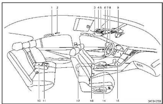
1 2 3 45 6 7 8 9 10 11 12 13 14 15 JVC0425X1.Coathooks(P.2-48)
2. Rearpersonallight(P.2-54)
3.Sunvisors(P.3-25)
4.Maplight(P.2-53)
—SOScallswitch(ilsoequipped)*
5.Moonroofswitch(ifsoequipped)
(P.2-51)
6. Sunglasses holder (P.2-46)
7. Power window switch (P.2-49)
8. Automatic drive positioner switch (if so equipped) (P.3-29)
9.Insidemirror
—Operation(P.3-26)
—HomeLink ^(1) universaltransceiver(if
soequipped)(P.2-56)
-Compass(ifsoequipped)(P.2-9)
10. Trunkpass-through/Reararmrest
(P.1-7)
11.Rearcupholders(P.2-44)
12.Rearashtray(ifsoequipped)(P.2-44)
13.Consolebox(P.2-47)
—Poweroutlet(P.2-43)
-Mediahub*
14.Frontcupholders(P.2-44)
15.Frontpassengerairbagstatuslight (P.1-49)
*:RelertotheInfinitiInTouchOwner's
Manual.
Illustratedtableofcontents0-5
COCKPIT
text_image
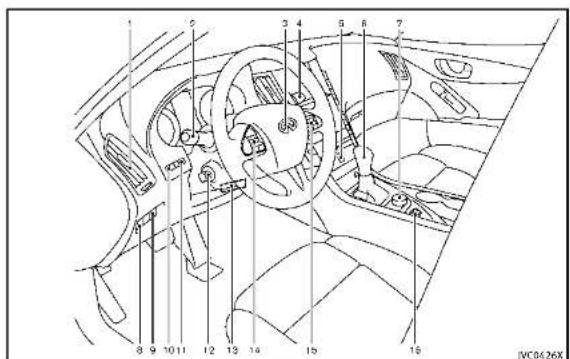
Technical diagram of a car interior with numbered components for identification- Sideventilator(P.4-2)
- Headlight, foglight and turnsignal switch(P.2-36)
-
Steeringwheel —Horn(P.2·42)
—Driversupplementalairbag (P.1-42) — Heated steering wheel (if so equipped)* — Steering system (P.5-104) -
Windshieldwiperandwasherswitch (P.2-33)
5.Hazardwarningflasherswitch(P.6-2)
6.Shiftlever(P.5-15)
7.INFINITIcontroller*
8.VehicleDynamicControl(VDC)OFF switch(P.2-43,P.5-108)
-
Trunklidreleaseswitch(P.3-19)
-
Instrument brightness control switch (P.2-41)
11.TRIP/RESETswitchfortwintripodometer(P.2-7)
-
Electric tilting/telescopic steering wheelswitch(ifsoequipped) (P.3-24)
-
Manualtilting/telescopicsteering wheellever(ifsoequipped)(P.3-24)
-
Steering-wheel-mounted controls(left side) —Audiocontrolsteeringswitch* —Hands-FreePhoneSystemswitch*
-
Steering-wheel-mounted controls (rightside) —Tripcomputerswitches(P.2-28) —Cruise control switches(ifso equipped)(P.5-56)
0-6Illustratedtableofcontents
—IntelligentCruiseControl(ICC)
switches(ifsoequipped)(P.5-58)
—Dynamicdriverassistanceswitch
(ifsoequipped)(P.5-30,P.5-37,
P.5-79)
16.INFINITIDriveModeSelector(P.5-21)
*:RefertotheInfinitiInTouchOwner's
Manual.

Illustratedtableofcontents0-7
INSTRUMENTPANEL
text_image
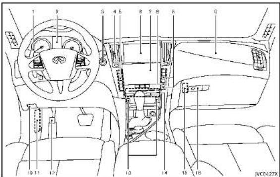
1 9 S 4 5 6 7 8 9 10 11 12 13 14 15 16 JMC0427X- Paddleshifter(ifsoequipped)(P.5-17)
2.Metersandgauges(P.2-6)
-Clock(P.2-30)
3.Push-buttonignitionswitch(P.5-10)
4. Centerventilator(P.4-2)
5.Automaticclimatecontrolsystem*
0-8Illustratedtableofcontents
6.Uppertouchscreendisplay(upper display)*andNavigationsystem(ifso equipped)*
7. Lower touch screen display (lower display)*
8. Rear window and outside mirror
defrosterswitch(P.2-36)
9.Frontpassengersupplementalairbag (P.1-42)
10.Hoodreleasehandle(P.3-18)
11.Fuseboxcover(P.8-22)
12. Parkingbrake(P.5-20)
13.Seatheaterswitch(ifsoequipped)*
14.Audiosystem*
15. Trunkreleasepowercancelswitch (P.3-20)
16.Glovebox(P.2-46)
*:RefertotheInfinitiInTouchOwner's Manual.
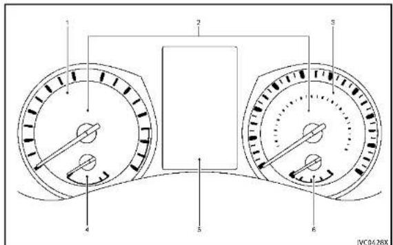
METERSANDGAUGES
text_image
1 2 3 4 5 6 JVC0428X- Tachometer(P.2-8)
- Warning/Indicatorlights(P.2-12)
3.Speedometer(P.2-7) - Enginecoolanttemperaturegauge (P.2-8)
- Vehicleinformationdisplay(P.2-20)/
Odometer/twintripodometer(P.2-7)
6.Fuelgauge(P.2-9)

Illustratedtableofcontents0-9
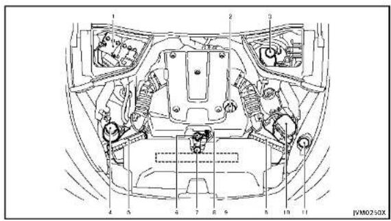
ENGINECOMPARTMENT
text_image
1 2 3 4 5 6 7 8 9 10 11 JVM02-50XVQ37VHRENGINE
1.Battery(P.8-15)
2. Engineoilfillercap(P.8-10)
3.Brakefluidreservoir(P.8-13)
4. Powersteeringfluidreservoir(ifso equipped)(P.8-13)
5.Aircleaner(P.8-19)
6.Radiatorfillercap(P.8-8)
7. Enginecoolantreservoir(P.8-8)
8.Engineoildipstick(P.8-10)
9.Enginedrivebeltlocation(P.8-17)
10.Fuse/fusiblelinkholder(P.8-22)
11. Windowwasherfluidreservoir (P.8-14)
0-10 illustratedtableofcontents

WARNINGANDINDICATORLIGHTS
| Warning light | NamePage | |
| ABS | Anti-lockBrakingSystem(ABS) warninglight | 2-12 |
| BRAKE | Brakewarninglight2-13 | |
| Chargewarninglight2-13 | ||
| Forwardemergencybraking systemWARNINGlight* | 2-13 | |
| LowFuelwarninglight2-14 | ||
| Lowtirepressurewarninglight2-14 | ||
| Masterwarninglight2-16 | ||
| Powersteeringwarninglight*2-16 | ||
| Seatbeltwarninglight2-16 | ||
| Supplementalairbagwarning light | 2-16 | |
| VehicleDynamicControl(VDC) warninglight | 2-17 |
| Indicator light | NamePage | |
| ECO | ECOdriveindicatorlight | 2-17 |
| Exteriorlightindicator2-17 | ||
| Fronttoplightindicatorlight | 2-17 | |
| Frontpassengerairbagstatuslight | 2-18 | |
| Highbeamassistindicatorlight* | 2-18 | |
| Highbeamindicatorlight | 2-18 | |
| MalfunctionIndicatorLight (MIL) | 2-18 | |
| Securityindicatorlight2-19 | ||
| Turnsignal/hazardindicatorlights | 2-19 | |
| VehicleDynamicControl(VDC)offindicatorlight | 2-19 |
*:ifsoequipped

Information Provided by: DEALER
Illustratedtableofcontents0-11
MEMO
0-12 illustratedtableofcontents

1 Safety—Seats, seat belts and supplemental restraintsystem
Seats....1-2
Frontseats....1-3
Rearseats....1-5
Armrest....1-7
Headrestraints/headrests....1-8
Adjustablehead
restraint/headrestcomponents....1-9
Non-adjustablehead
restraint/headrestcomponents....1-9
Remove....1-9
Install....1-10
Adjust....1-10
Seatbelts....1-1
Precautionsonseatbeltusage....1-12
Pregnantwomen....1-14
Injuredpersons....1-14
Pre-crashseatbeltswithcomfortfunction
(frontseats)(ifsoequipped)....1-14
Three-pointtypeseatbelt....1-15
Seatbeltextenders....1-21
Seatbeltmaintenance....1-21
Child safety 1-22
Infants.... 1-23
Small children 1-23
Larger children 1-23
Childrestraints....1-24
Precautionsonchildrestraints....1-24
LowerAnchorsandTethersforChildren
System(LATCH)....1-26
Rear-facingchildrestraintinstallation
usingLATCH....1-28
Rear-facingchildrestraintinstallationusing
theseatbelts....1-30
Forward-facingchildrestraintinstallation
usingLATCH....1-33
Forward-facingchildrestraintinstallation
usingtheseatbelts....1-35
Installingtoptetherstrap......1-38
Boosterseats....1-39
Supplementalrestraintsystem....1-42
Precautionsonsupplemental
restraintsystem....1-42
INFINITI AdvancedAirBagSystem
(frontseats)....1-4/
Frontseat-mountedside-impactsupplemental
airbagandroof-mountedcurtainside-impact
supplementalairbagsystems....1-52
Seat beltwithpretensioners(frontseats)....1-54
Supplementalairbagwarninglabels....1-55
Supplementalairbagwarninglight......1-55
Repair and replacement procedure....1-56
SEATS

natural_image
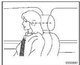
Line drawing of a person sitting in a car, viewed from the side (no text or symbols present)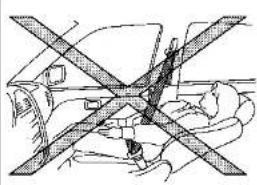
natural_image
Diagram of a car interior showing cross-section of seatbelt and seatbelt (no text or labels)5550133

WARNING
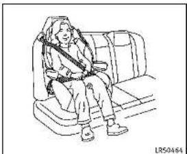
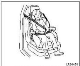
- Donotrideinamovingvehiclewhen the seatbackisreclined. This can be dangerous. Theshoulderbeltwill not be against your body. In an accident, you could be thrown into it and receive no other serious injuries. You could also slide under the lap belt and receive serious internal injuries.
- Forthemosteeffectiveprotectionwhen thevehicleisinmotion,theseatshould beupright.Alwayssitwellbackinthe
seatwithbothfeetonthefloorand adjusttheseatbeltproperly.See"Pre- cautionsonseatbeltusage"(P.1-12).
- Donotleavechildrenunattendedinside thevehicle. Theycouldunknowingly activateswitchesorcontrols.Unattendedchildrencouldbecomeinvolved inseriousaccidents.
- Theseatbackshouldnotbereclined further than necessary for comfort. Seat belts are most effective when the passenger sits well back and straight up in the seat. If the seatback is reclined, the risk of sliding under the lap belt and
beinginjuredisincreased.

CAUTION
When adjusting theseatpositions, besure nottocontactanymovingpartstoavoid possibleinjurlesand/ordamages.
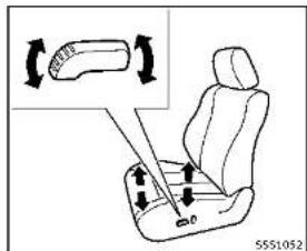
FRONTSEATS
Frontpowerseatadjustment
Operatingtips:
■Thepowerseatmotorhasanauto-reset overloadprotectioncircuit.Ifthemotor stopsduringoperation,wait30seconds,thenreactivatetheswitch.
- Donotoperatethepowerseatswitch foralongperiodoftimewhenthe engineisoff. Thiswilldischarge the battery.
See "Automaticdrivepositioner" (P.3-29) for theseatpositionmemoryfunction(ifso equipped).

text_image
Diagram illustrating seatbelt usage with labeled parts and directional arrows indicating movement or positioning.Forwardandbackward:
Movingtheswitch ① forwardorbackward willslidetheseatforwardorbackwardto thedesiredposition.
Reclining:
Movethereclineswitch ② backwarduntil thedesiredangleisobtained. Tobringthe seatbackforwardagain, movetheswitch ② forward.
Therecliningfeatureallowsadjustmentof the seatback for occupants of different sizes for added comfort and to help obtain proper seat belt fit. (See "Precautions on seat belt usage" (P.1-12).) Also, the seat-
backcanbereclinedtoallowoccupantsto restwhenthevehicleisparked.
text_image
Diagram showing car seat assembly with directional arrows and a magnified inset of the seat structureSeatlifter:
Pushthefrontorrearendoftheswitchup ordowntoadjusttheangleofthefront portionorheightoftheseat.

text_image
C2 C0 55S1053TypeA
Lumbarsupport(ifsoequipped): Thelumbarsupportfeatureprovideslower backsupportlothedriver. TypeA Pushthefrontorbackendoftheswitchto adjusttheseatbacklumbararea.

text_image
① 5550836TypeB
TypeB
Movethelever ① upordowntoadjustthe seatbacklumbararea.


text_image
Diagram of car seatbelt with numbered labels and directional arrows indicating seat movementSidesupport(ifsoequipped):
Thesidesupportfeatureallowstoadjust thetorsosupports.Pushtheswitchinside ① oroutside ② toadjustthetorsoarea.

text_image
Diagram showing a car seat with labeled parts and an inset view of the seat's seatbelt mechanism.Thighextension(ifsoequipped):
Thefrontportionofthefrontseatscanbe extendedforwardforseatingcomfort.Pull upandholdthelever ① toextendthe frontportionlothedesiredposition.
Heatedseats(ifsoequipped)
Thefrontseatsarewarmedbybuilt-in heaters. Theswitcheslocatedonthe instrumentpanelcanbeoperatedindependentlyofeachother.
For details, see the Infiniti InTouch Owner's Manual.

REARSEATS
Folding(ifsoequipped)

WARNING
- NeverallowanyonetorIdelinthetrunk orontherearseatwhenitisinthefolddownposition.Useoftheseareasby passengerswithoutproperrestraints couldresultinseriousinjuryinan accidentorsuddenstop.
•Properlysecureallcargowithropesor strapstohelppreventitfromslidingor shifting.Donotplacecargohigherthan theseatbacks.Inasuddenstopor collision,unsecuredcargocouldcause personalinjury.
- When returning these seat back to the upright position, be certain they are completely secured in the latched position. If they are not completely secured, passengers maybe injured in an accidentors sudden stop.
•Closelysupervisechildrenwhentheyare aroundcarstopreventthemfromplayingandbecominglockedinthetrunk wheretheycouldbeseriouslyinjured. Keepthecarlocked,withtherear
Safety — Seats, seat belts and supplemental restraint system
seatbackandtrunklidsecureylatched whennotinuse,andpreventchildren's accesstocarkeys.
text_image
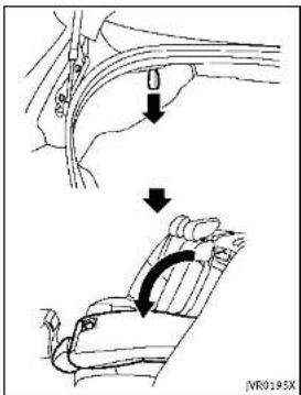
IVR0195XTherearseatbackcanbefoldedaccording tothefollowingprocedure.
Before folding the seatback:
- Disconnect and stow the center seat belt and tongue into the retractor base. (See "Rear center seat belt (models with rear seat folding)" (P.1-18).)
●Alwaysreconnectthecenterseatbelt whentheseatisreturnedtotheupright position.
- Removedrinkcontainersfromtherear cupholder.
Tofoldtheseatback:
-
Openthetrunklid.
-
Pullthestraplocatedontheleftand rightsideofthetrunk.Therearseat-backwillbeunlatched.
3.Foldtherearseatbackdown.
Toreturntheseatback:
1.Folduptherearseatback.
- Securelylocktheseatbackinposition.

natural_image
Diagram of a car seatbelt with a black arrow indicating direction (no text or symbols)ARMREST
Reararmrest
Pullthearmrestforwarduntilitishhorizontal.
text_image
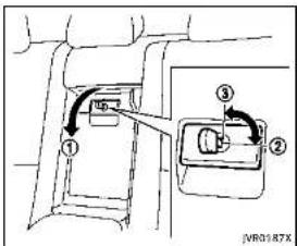
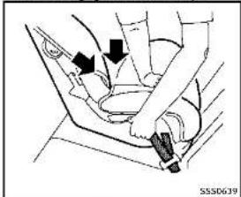
Technical diagram showing a mechanical assembly with numbered components and directional arrows indicating motion or movement.Trunkpass-through
Therearcenterseatbackcanbefoldedto allowtrunkaccessfrominsideofthe vehicle.
Toaccesssthetrunk,pulldowntherear centerarmrestandpulloutthetrunkpass-throughlid ①.
Tolockthelid, usethemechanicalkey and turnittotheLOCK position ②. Tounlock, turnthemechanicalkeytotheUNLOCK position ③. For the mechanical key usage see "Keys" (P.3-2).
Make sure that the mechanical key is removed from the trunk pass-through lid
keycylinderbeforeopeningorclosingthe lid. Otherwisethelidandthereararmrest maybedamaged.
HEADRESTRAINTS/HEADRESTS

WARNING
Headrestraint/headrestsupplementthe othervehiclesafetysystems. Theymay provideadditionalprotectionagainstinjury incertainareendcollisions. Adjustthe headrestraint/headrestproperly,asspecifiedinthissection.Checkheadjustmentaltsomeoneelseusestheseat.Donot attachanythingtotheheadrestraint/headreststalksorremovetheheadrestraint/headrest.Donotusetheseatifthehead restraint/headresthasbeenremoved.Ifthe headrestraint/headrestwasremoved,reinstallandpropertyadjusttheheadrestraint/headrestbefereanoccupantuses theseatingposition.Failureforefolowthese instructionscanreducetheeffectivenessof theheadrestraint/headrest. Thismayincreaseatherlskofseriousinjuryordeathina collision.

natural_image
Top-down line drawing of a car with four directional arrows and triangular markers (no text or symbols)The illustrations show these seating positions equipped with head restraint/head-rest.
▲ Indicate theseating position is equipped with a head restraint.
■ Indicate theseating position is equipped with a headrest. +indicate theseating position is not equipped with a head restraint or head rest.
- Your vehicle is equipped with a head restraint/headrest that may be integrated, adjustable or non-adjustable.
-Adjustableheadrestraints/headrests havemultiplenotchesalongthestalk tolocktheminadesiredadjustment position.
- Thenon-adjustableheadrestraints/headrestshavesinglelockingnotchto securethemtotheseatframe.
●ProperAdjustment:
—fortheadjustabletype, alignthe headrestraint/headrestsothecenterofyourarisapproximatelylevel withthecenteroftheheadrestraint/headrest.
- If you are position is still higher than there recommended alignment, placethe head restraint/head rest at the highest position.
- If the head restraint/head rest has been removed, ensure that it is reinstalled and locked in place before reiding in that designated seating position.

text_image
1 2 3 4 5 5550992ADJUSTABLEHEADRESTRAINT/ HEADRESTCOMPONENTS
- Removableheadrestraint/headrest
- Multiplenotches
3.Lockknob
4.Stalks

text_image
1 2 3 4 JNR0203XNON-ADJUSTABLEHEADRESTRAINT/HEADRESTCOMPONENTS
- Removableheadrestraint/headrest
- Singlenotch
3.Lockknob
4.Stalks
natural_image
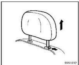
Simple line drawing of a seatbelt with an arrow indicating upward motion (no text or symbols)REMOVE
Use the following procedure to remove the head restraint/headrest.
- Pulltheheadrestraint/headrestupto thehighestposition.
2.Pushandholdthelockknob.
-
Removetheheadrestraint/headrest fromtheseat.
-
Storetheheadrestraint/headrestprop- erlyinasecureplacesoitisnotloose inthevehicle.
-
Reinstallandproperlyadjustthehead restraint/headrestbeforeanoccupant

Safety — Seats, seat belts and supplemental restraint system
usestheseatingposition.
text_image
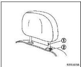
① ② 5551038INSTALL
- Align the head restraint/headrest stalks with the holes in these seat. Make sure that the head restraint/headrest is facing the correct direction. The talk with the adjustment notch ① must be installed in the hole with the lock knob ②.
2.Pushandholdthelockknobandpush
theheadrestraint/headrestdown. - Properly adjust the head restraint/headrest before an occupant uses the seating position.
natural_image
Side profile illustration of a person in a car seat, viewed from the side (no text or symbols)ADJUST
Foradjustableheadrestraint/headrest
Adjusttheheadrestraint/headrestsothe centerislevelwiththecenterofyourears. Ifyourearpositionisstillhigherthanthe recommendedalignment, placethehead restraint/headrestatthehighestposition.

natural_image
Diagram of a mechanical or electrical component with intersecting beams and a central oval shape, no visible text or symbols.Fornon-adjustableheadrestraint/headrest Makesuretheheadrestraint/headrestis positionedsothelockknobisengagedin thenotchbeforeridinginthatdesignated seatingposition.

natural_image
Simple line drawing of a car seat with an arrow indicating upward motion (no text or symbols)Raise
Toraisetheheadrestraint/headrest, pullit up.
Makesuretheheadrestraint/headrestis positionedsothelockknobisengagedin thenotchbeforeridinginthatdesignated seatingposition.

natural_image
Simple line drawing of a seatbelt with an arrow indicating rotation (no text or symbols)Lower
Tolower, pushandholdthelockknoband pushtheheadrestraint/headrestdown. Makesuretheheadrestraint/headrestis positionedsothelockknobisengagedin thenotchbeforeridinginthatdesignated seatingposition.

Safety - Seats, seat belts and supplemental restraint system
SEATBELTS
PRECAUTIONSONSEATBELTUSAGE
If you are wearing your seat belt properly adjusted, and you are sitting upright and well back in your seat with both feet on the floor, your chances of being injured or killed in an accident and/or these severity of injury may beg greatly reduced. INFINITI strongly encourages you and all of your passenger to buckle up every time you drive, even if your seating position includes as supplemental airbag.
MostU.S. states and Canadian provinces or territories specify that seat belts be worn at all times when vehicle is being driven.

natural_image
Diagram of a car seatbelt mechanism with no visible text or symbols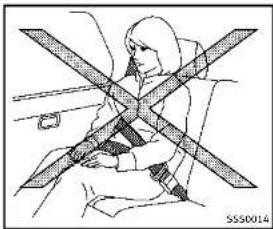
natural_image
Line drawing of a person sitting on a vehicle with a cross-shaped object between them (no text or symbols)
WARNING
- Everypersonwhodrivesorridesinthis vehicleshoulduseaseatbeltatall times. Childrenshouldbepropertyrestrainedintherearseatand,ifappropriate,inachildrestraint.
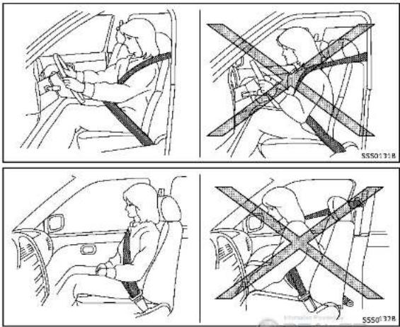
•Theseatbeltshouldbeproperlyadjustedtoasnugfit.Failureretodosomay reducetheeffectivenessoftheentire restraintsystemandinincreasethechance orseverityofinjuryinanaccident. Seriousinjuryordeathcanoccurifthe seatbeltisnotwornproperly.
•Alwaysroutetheshoulderbeltoveryour shoulderandacrossyourchest.Never runthebeltbehindyourback,under yourarmoracrossyourneck.Thebelt shouldbeawayfromyourfaceandneck, butnotfallingoffyourshoulder. - Positionthelapbeltaslowandsnugas possibleAROUNDTHEHIPS,NOTTHE WAIST.Alapbeltworntoohighcould Increase the risk of internal injuries in an accident.
-
Be sure the seat belt tongue is securely fastened to the proper buckle.
-
Donotweartheseatbeltinsideoutortwisted.Doingsomayreduceitseffectiveness.
- Donotallowmorethanoneperson to usethesameseatbelt.
●Nevercarnymorepeopleinthevehicle thanthereareseatbelts. - If these seat belt warning light glows continuously while the ignition is turned ON with all doors closed and all seat belts fastened, it may indicate an function in the system. Havethesystem checked by an INFINIT retailer.
- Nochangesshouldbemadetotheseat beltsystem. Forexample, donotmodify theseatbelt, addmaterialorinstall devicesthatmaychangetheseatbelt routingortension. Doingsomayaffect theoperationoftheseatbeltsystem. Modifyingortamperingwiththeseat beltsystemmayresultinseriouspersonalinjury.
- Once a seat belt pretensioner has activated, it cannot be reused and must bere placed together with theretractor. Sean INFINIT retailer.
●Removalandinstallationofthepretensionerseatbeltsystemcomponents
shouldbedonebyanINFINITretailer.
- Allseatbeltassemblies, including retractorsandattachinghardware, should beinspectedafteranycollisionbyan INFINITretailer.INFINITirecommends thatallseatbeltassembliesinuse duringacollisionbereplacedunless thecollisionwasminorandthebelts showmodamageandcontinuetooperateproperly.Seatbeltassembliesnotin useduringacollisionshouldalsobe inspectedandreplacedfeitherdamage orimproperoperationisnoted.
- Allchildrestraintsandattachinghard-wareshouldbeinspectedafterany collision.Alwaysfollowtherestraint manufacturer'sinspectioninstructions andreplacementrecommendations.The childrestraintsshouldbereplacedif theyaredamaged.
PREGNANTWOMEN
INFINITrecommendsthatpregnantwomen useseatbelts.Theseatbeltshouldbe wornsnug,andalwayspositionthelap beltaslowaspossiblearoundthehips, notthewaist,andplacetheshoulderbelt overyourshoulderandacrossyourchest.
Neverrunthelap/shoulderbeltoveryour abdominalarea.Contactyourdoctor for specific recommendations.
INJUREDPERSONS
INFINITIrecommendsthatinjuredpersons useseatbelts,dependingontheinjury. Checkwithyourdoctorforspecificrecommendations.
PRE-CRASHSEATBELTSWITHCOM-FORTFUNCTION(frontseats)(ifso equipped)
The pre-crash seat belt tighten these seat bell with a motortohelprestrain front seat occupants. This helps reduce the risk of injury in ac collision.
Themotorretractstheseatbeltunderthe followingemergencyconditions:
●Duringemergencybraking
- Duringsuddensteeringmaneuvers - Activationoftheforwardemergency brakingsystem.(See"Forwardemer- gencybrakingsystem"(P.5-89).)
The pre-crash seat belt will not be active when:
• the seat belt is not fastened
- thevehiclespeedisunder10MPH(15 km/h)duringemergencybraking - thevehiclespeedisunder19MPH(30 km/h)duringsuddensteeringmaneuvers
The pre-crash seat belt will not be active when the brake pedal is not depressed except when sudden steering maneuvers occur and the forward emergency braking system activates.
Themotoralsoretractstheseatbeltwhen theseatbeltisfastenedorunfastened. Whentheseatbeltisfastened,themotor tightenstheseatbeltforasnugfit.When theseatbeltisunfastened,themotor retractstheseatbelt.Iftheseatbeltisnot fullyretracted,themotorretractstheseat beltwhenthedoorisopened.
Alwayswearyourseatbeltcorrectlyandsit uprightandwellback.
Ifthemotorcannotretracttheseatbelt whentheseatbeltisfastenedorunfastened,itmayindicatethepre-crashseat beltsystemhasamalfunction.Haveyour INFINITretailercheckandrepairthe system.
Whentheseatbeltisretractedrepeatedly inashortperiodoftime,themotormay
notbeabletoretracttheseatbelt. After a few minutes, themotorreactivates and retracttheseatbelt. If theseatbelt still cannot be extracted by themotor, the pre-crash seatbeltsystem has a malfunction. Have your INFINIT retailer check and repair the system.
THREE-POINTTYPESEATBELT

WARNING
- Everypersonwhodrivesorridesinthis vehicleshoulduseaseatbeltatall times.
- Donotrideinamovingvehiclewhenthe seatbackisreclined. Thiscanbedangerous. Theshoulderbeltwillnotbe againstyourbody.Inanaccident,you couldbethrownintoltandreceiveneck orotherseriousinjuries.Youcouldalso slideunderthelapbeltandreceive seriousinternalinjuries.
- For themosteeffective protection when the vehicle is in motion, theseat should be upright. Always sit well back in the seat with both feet on the floor and adjust these at belt properly.

text_image
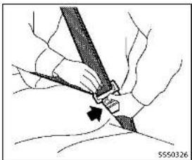
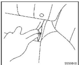
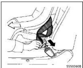
Technical diagram showing a mechanical assembly with labeled parts and directional arrows, likely illustrating a procedure or assembly step.Modelswithrearseatfolding
released.Releasetheconnectortongueby insertingasuitabletool(suchasakey)into theconnectorbuckle ⚠.Iftheseatbelt cannotbeunbuckledorisalreadyun-buckled,releasethechildbycuttingthe seatbeltwithasuitabletool(suchasa knifeorscissors)toreleasetheseatbelt.

WARNING
Donotallowchildrentoplaywiththeseat belts.Mostseatingpositionsareequipped withAutomaticLockingRetractor(ALR) modeseatbelts.Iftheseatbeltbecomes wrappedarounddachild'sneckwiththeALR modeactivated,thechildcanbeseriously injuredorkilledIftheseatbeltretractsand becomes tight.This can occur even if the vehicle is parked.Unbuckle the seat belt to release the child. For the center of the rear seat on the models with rear seat folding, thecon nector tongue ① may also
Safety — Seats, seat belts and supplemental restraint system

natural_image
Line drawing of a person seated in a car seatbelt, no text or symbols presentFasteningtheseatbelts
-
Adjusttheseat.(See"Seats"(P.1-2).)
-
Slowlypulltheseatbeltoutofthe retractorandinsertthetongueintothe buckleuntilyouhearandfeelthelatch engage.
-
Theretractorisdesignedtolock duringasuddenstoporonimpact. Aslowpullingmotionpermitsthe belttomove, andallowsyousome freedomofmovementintheseat.
- iftheseatbeltcannotbepulled fromitsfullyretractedposition, firmlypullthebeltandreleaseit.
Thensmoothlypullthebeltoutof theretractor.

natural_image
Line drawing of a person sitting in a car seatbelt, no text or symbols present-
Positionthelapbeltporionlowand snugonthehipsasshown.
-
Pulltheshoulderbeltportiontoward theretractortotakeupextraslack. Be suretheshoulderbeltisroutedover yourshoulderandacrossyourchest.
Thethree-pointtypeseatbeltshavetwo modesofoperation:
●EmergencyLockingRetractor(ELR)
●AutomaticLockingRetractor(ALR)
The Emergency Locking Retractor (ELR) mode allow these seat belt to extend and retract to allow the driver and passengers some freedom of movement in these seat.
TheELRlockstheseatbeltwhenthe vehicleslowsdownrapidlyorduring impacts.
TheAutomaticLockingRetractor(ALR) mode(childrestraintmode)lockstheseat beltforchildrestraintinstallation.
WhentheALRmodeisactivatedtheseat belt cannot be extended again until the seatbelt tongue is detached from the buckleandfullyretracted. Theseat belt return to the ELRmode after theseat belt fully retracts. For additional information, see "Childrestraints" (P.1-24).
The ALR modes should be used only for child restraint installation. During normal seat belt use by an occupant, the ALR modes should not be activated. If it is activated, it may cause uncomfortable seat beltension.

WARNING
When fastening these at belts, be certain that seat backs are completely secured in the latched position. If they are not completely secured, passengers may be injured in an accidentors sudden stop.
natural_image
Illustration of a person's seatbelt being adjusted for a piece, with no visible text or symbols●Grasptheshoulderbeltandpull forwardquickly. Theretractorshould lockandrestrictfurtherbeltmovement. Iftheretractordoesnotlockduringthis checkorifyouhaveanyquestionabout seatbeltoperation,seeanINFINITlretailer.
Unfasteningtheseatbelts
Tounfastentheseatbelt, pushthebutton onthebuckle. Theseatbeltautomatically retracts.
Checkingseatbeltoperation
Seatbeltretractorsaredesignedtolock seatbeltmovementbytwoseparate methods:
- When the belt is pulled quickly from the retractor.
- When the vehicle slows down rapidly. To increase your confidence in the seat belts, check the operation as follows:
natural_image
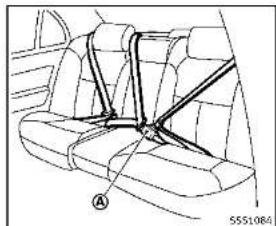
Diagram of a car interior showing seatbelt and armrest (no text or symbols)Centerofrearseat
Thecenterseatbeltbuckleisidentifiedby theCENTERmark Ⓐ. Thecenterseatbelt tongue can be fastened only into the center seatbelt.
text_image
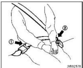
Diagram showing a person's seatbelt with labeled parts and directional arrows indicating movement or positioning.Rearcenterseatbelt(modelswith rearseatfolding)
Therearcenterseatbelthasaseatbelt tongue ① andaconnectortongue Boththeconnectortongueandtheseat beltonguemustbesecurelylatchedfor properseatbeltoperation.
natural_image
Diagram of a car steering wheel assembly with no visible text or symbols
WARNING
●Alwaysfastentheconnectortongueand theseatbeltintheordershown.
●Alwaysmakesureboththeconnector tongueandtheseatbeltongueare securedwhenusingtheseatbeltor installingachildrestraint.Donotuse theseatbeltorchildrestraintwithonly theseatbelttongueattached.Thiscould resultinseriouspersonalljuryincase ofanaccidentorasuddenstop.

text_image
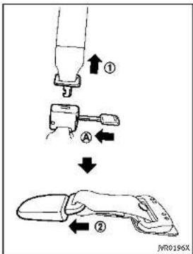
① A ② JVR0196XStowingrearcenterseatbelt:
When folding down there are seat, there are center seat belt can be retracted into a stowed position as follows:
- Holdtheconnectortongue ① sothat theseatbeltdoesnotretractsuddenly whenthetongueisreleasedfromthe
connectorbuckle.Releasetheconnectortonguebyinsertingasuitabletool suchaskey Ⓐ intotheconnector buckle.
- Then secure the connector tongue into theretractor base ②.
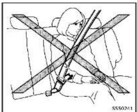
WARNING
- Donotunfastentherearcenterseatbelt connectorexceptwhenfoldingdownthe rearseat.
- When attaching therearcenterseatbelt connector, be certain that these seatbacks are completely secured in the latched position and therearcenterseatbelt connector is completely secured.
- Iftherearcenterseatbeltconnector and theseatbacksarenotsecured in the correct position, serious personal injury may result in an accidentorsudden stop.


text_image
② ↓ ③ IVR0197XAttachingrearcenterseatbelt:
Alwaysbesuretherearcenterseatbelt connectorlongueandconnectorbuckleare attached.Disconnectonlywhenfolding downtherearseat.
Toconnectthebuckle:
-
Pullouttheconnectortonguefromthe retractorbase ②.
-
Pulltheseatbeltandsecurethe connectorbuckleuntilitclicks ③.
Thecenterseatbeltconnectortongueand buckleareindicatedbythe▼and▲ mark.
The centerseat belt connector tongue can be attached only into the rear center seat belt connector buckle.
Tofastentheseatbelt, see "Fasteningthe seatbelts" (P.1-16).

WARNING
- Donotunfastentherearcenterseatbelt connectorexceptwhenfoldingdownthe rearseat.
- When attaching therearcenterseatbelt connector, becertainthattheseatbacks arecompletelysecuredinthelatched positionandtherearcenterseatbelt connectorscompletelysecured.
- If therearcenterseatbeltconnector and theseatbacksarenotsecured in the correct position, serious personal injury may result in an accidentorsudden
stop.
text_image
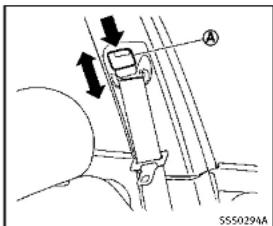
A SS50294AShoulderbeltheightadjustment (frontseats)
Theshoulderbeltanchorheightshouldbe adjustedtothepositionbestforyou.(See "Precautionsonsealtbellusage"(P.1-12).)
Toadjust, pushthebutton Ⓐ, and then movelheshoulder beltanchor to the desired position, so that the belt passes over the center of the shoulder. The belt should be away from your face and neck, but not falling off your shoulder. Release the adjustment button to lock the shoulder belt anchor intoposition.

WARNING
- Afteradjustment, releasetheadjustment buttonandtrytomovetheshoulderbelt anchorupanddowntomakesureltis securelyfixedinposition.
• Theshoulderbeltanchorheights should beadjusted to the position best for you. Failure to dosomay reduce the effectiveness of the entire restraints system and increase the chance or severity of injury in an accident.
SEATBELTEXTENDERS
If, because of body size or driving position, it is not possible to properly fit the lap shoulder belt and fastenit, an extender that is compatible with the installed seat belts is available that can be purchased. The extender adds approximately 8 in (200 mm) of length and may be used for either the driver or front passenger seating position. Sean INFINIT retailer for assistance with purchasing an extender if an extender is required.

WARNING
- OnlyINFINITIseatbeltextenders, made bythesamecompanywhichmadethe originalequipmentseatbelts, shouldbe usedwiththeINFINITIseatbelts.
- Adultsandchildrenwhocanusethe standardseatbeltshouldnotusean extender.Suchunnecessaryusecould resultinseriouspersonalinjuryinthe eventofanaccident.
- Neveruseseatbeltextenderstoinstall childrestraints.Ifthechildrestraintis notsecuredproperly,thechildcouldbe seriouslyinjuredinacollisionora suddenstop.
SEATBELTMAINTENANCE
- Tocleantheseatbeltwebbing,applya mildsoapsolutionoranysolution recommendedforcleaningupholstery orcarpets.Then,wipewithaclothand allowtheseatbeltstodryintheshade. Do not allow the seat belts to retract until they are completely dry.
- If dirt builds up in the shoulder belt guide of the seat belt anchors, the seat
beltsmayretractslowly.Wipethe shoulderbeltguidewithaclean,dry cloth.
Periodicallychecktoseethattheseat beltandthemetalcomponentssuchas buckles,tongues,retractors,flexible wiresandanchorsworkproperly.if looseparts,deterioration,cutsorother damageonthewebbingisfound,the entireseatbeltassemblyshouldbe replaced.
CHILDSAFETY
text_image
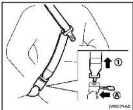
JNR0256XModelswithrearseatfolding

WARNING
Donotallowchildrentoplaywiththeseat belts.Mostseatingpositionsareequipped withAutomaticLockingRetractor(ALR) modeseatbelts.Iftheseatbeltbecomes wrappedarounddachild'sneckwiththeALR modeactivated,thechildcanbeseriously injuredorkillediftheseatbeltretractsand becomesight.Thiscanoccrevenifthe vehicleisparked.Unbuckletheseatbeltto releasethechild.Forthecenteroftherear seatonthemodelswithrearseatfolding, theconnectortongue ① mayalsob
released. Releasetheconnectortongueby insertingasuitabletool(suchasakey)into theconnectorbuckle Ⓐ. If theseatbelt cannotbeunbuckledorisalreadyunbuckled, releasethechildbycutting the seatbeltwithasuitabletool(suchasa knifeorscissors)toreleasetheseatbelt.
Childrenneedadultstohelpprotectthem. Theyneedtobeproperlyrestrained.
Inadditiontothegeneralinformationin thismanual,childsafetyinformationis availablefrommanyother sources,includingdoctors,teachers,governmenttraffic safetyoffices,andcommunityorganizations.Everychilddisdifferent,sobesureto learnthebestwaytotransportyourchild. Therearethreebasictypesofchild restraintsystems:
•Rear-facingchildrestraint
●Forward-facingchildrestraint
- Boosterseat
The proper restraint depends on the child's size. Generally, infants up to about 1 year and less than 20 lbs (9 kg) should be placed in rear-facing child restraints. Forward-facing child restraints are available for children who outgrow rear-facing child
restraintsandareatleast1yearold. Boosterseatsareusedtohelppositiona vehiclelap/shoulderbeltonachildwho cannolongeruseaforward-facingchild restraint.

WARNING
Infantsandchildrenneedspecialprotection. Thevehicle'sseatbeltsmaynotfitthem properly.Theshoulderbeltmaycometoo closetothefaceorneck.Thelapbeltmay notfitovertheirsmallhipbones.Inan accident,animproperlyfittingseatbelt couldcausesereliousorfatalinjury.Always useappropriatechildrestraints.
AllU.S. states and Canadian provinces or territories require the use of approved child restraints for infants and small children. See "Child restraints" (P.1-24). A child restraints may be secured in the vehicle by using either the LATCH (Lower Anchor and Tethers for Children) system or with the vehicle seat belt. See "Child restraints" (P.1-24) form more information.
INFINITIrecommendsthatallpre-teens andchildrenberestrainedintherearseat. Studiesshowthatchildrenaresaferwhen properlyrestrainedintherearseatthanin thefrontseat.
Thisisespeciallyimportantbecauseyour vehiclehasasupplementalrestraintsystem(Airbagsystem)forthefrontpassenger.See"Supplementalrestraintsystem" (P.1-42).
INFANTS
Infantsuptoatleast1yearoldshouldbe placedinarear-facingchildrestraint. INFINITIrecommendsthatinfantsbeplaced inchildrestraintsthatcomplywithFederal MotorVehicleSafetyStandardsorCanadianMotorVehicleSafetyStandards.You shouldchooseachildrestraintthatfits yourvehicleandalalwaysfollowthemanufacturer'sinstructionsforinstallationand use.
SMALLCHILDREN
Childrenthatareover1yearoldandweigh atleast20lbs(9kg)shouldremainina rear-facingchildrestraintaslongas possibleuptotheheightorweightlimit ofthechildrestraint.Childrenwhooutgrow theheightorweightlimitoftherear-facing childrestraintandareatleast1yearold shouldbesecuredinaforward-facingchild restraintwithaharness.Refertothe manufacturer'sinstructionsfominimum andmaximumweightandheightrecommendations.INFINITrecommendsthat smallchildrenbeplacedinchildrestraints thatcomplywithFederalMotorVehicle SafetyStandardsorCanadianMotorVehicleSafetyStandards.Youshouldchoose childrestraintthatlitsyourvehicleand alwaysfollowthemanufacturer's instructionsforinstallationanduse.
LARGERCHILDREN
Childrenshouldremaininaforward-facing childrestraintwithaharnessuntilthey reachthemaximumheightorweightlimit allowedbythechildrestraintmanufacturer.
Onceachildoutgrowstheheightorweight limitoftheharness-equippedforward-facingchildrestraint,INFINITirecommends thatthechildbeplacedinacmercially availableboosterseattoobtainproper seat belt fit. For a seat belt to fit properly, the booster seat should raise the child so that the shoulder belt is properly positioned across the chest and the top, middle portion of the shoulder. The shoulderbeltshouldnotcrosstheneck orfaceandshouldnotfallofftheshoulder. Thelapbeltshouldliesnuglyacrossthe lowerhipsorupperthighs,nottheabdomen.
Aboosterseatcanonlybeusedinseating positionsthathaveathree-pointtypeseat belt. Theboosterseatshouldliththevehicle seatandhavelabelcertifyingthatit complieswithFederalMotorVehicleSafety StandardsorCanadianMotorVehicle SafetyStandards. Oncethechildhas grownsotheshoulderbeltisnolonger onorneathefaceandneck, andthelap beltcanbepositionedproperlyacrossthe lowerhipsorupperthighs, usetheseat beltwithouttheboosterseat.

WARNING
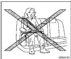
Neverletachildstandorkneelonanyseat anddonotallowachildinthecargoarea. Thechildcouldbeseriouslyinjuredorkilled inasuddenstoporcollision.
CHILDRESTRAINTS
natural_image
Diagram of a car interior showing two people seated, with no visible text or symbols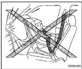
natural_image
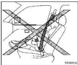
Diagram of a car seatbelt with diagonal lines indicating safety or comfort (no text or symbols)PRECAUTIONSONCHILDRESTRAINTS
WARNING
●Failuretofollowthewarningsand instructionsforproperuseandinstallationofchildrestraintscouldresultin seriousinjuryordeathofachildorother passengersinasuddenstoporcollision:
— Thechildrestraintmustbeusedand installedproperly.Alwaysfollowall ofthechildrestraintmanufacturer's instructionsforinstallationanduse.
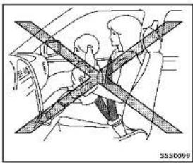
— Infantsandchildrenshouldneverbe heldonanyone'slap. Even the strongestadultcannotresistthe forcesofacollision.
— Donotputaseatbeltaroundbotha childandanotherpassenger.
— INFINITIrecommendsthatallchild restraintsbeinstalledintherear seat.Studlesshowthatchildrenare safer when properly restrained in the rear seat than in the front seat. If you must install a forward-facing child restraint in the front seat, see "for-
ward-facingchildrestraintinstallationusingtheseatbelts" (P.1-35).
EvenwiththeINFINITlAdvancedAir BagSystem,neverinstallarear-facingchildrestraintinthefront seat.Aninflatingairbagcould seriouslyinjureorkillachild.A rear-facingchildrestraintmustonly beusedintherearseat.
— Besuretopurchaseachildrestraint that will fit the child and vehicle. Some children restraint may not fit properly in your vehicle.
— Childrestraintanchorpointsare designedtowithstandloadsfrom childrestraintsthatareproperly fitted.
— Neverusetheanchorpointsfor adultseatbeltsorharnesses.
— Achildrestraintwithatoptether strapshouldnotbeusedinthefront passengerseat.
- Keepseatbacksasuprightaspossibleafterfittingthechildrestraint.
— Infantsandchildrenshouldalways beplacedinanappropriatechild restraintwhileinthevehicle.
- When the child restraint is not in use, keep it secured with the LATCH system or seat belt. In as sudden stop or collision, loose object scan injure occupants sordamagethe vehicle.

CAUTION
Achildrestraintinaclosedvehiclecan becomeveryhot. Checktheseatingsurface andbucklesbeforeplacingachildinthe childrestraint.
This vehicle is equipped with a universal child restraint anchors system, referred to asthe LATCH (Lower Anchors and Tethers for Children) system. Some child restraints includerigidor webbing-mounted attachments that can be connected to these anchors.
Fordetails, see "LowerAnchorsand TethersforChildrenSystem(LATCH)"(P.1-26).
If you donothave a LATCH compatible childe restraint, the vehicle seat belt scan be used.
Severalmanufacturersofferchildrestraints
forinfantsandsmallchildrenofvarious sizes. Whenselectinganychildrestraint, keepthefollowingpointsinmind:
- Chooseonlya restraintwithalabel certifyingthatitcomplieswithFederal MotorVehicleSafetyStandard213or CanadianMotorVehicleSafetyStandard213.
- Checkthechildrestraintinyourvehicle tobesureitiscompatiblewiththe vehicle'sseatandseatbeltsystem.
- If the child restraint is compatible with your vehicle, place your child in the child restraint and check the various adjustments to be sure the child restraint is compatible with your child. Choose each child restraint that is designed for your child's height and weight. Always follow all recommended procedures.
AllU.S.statesandCanadianprovincesor territoriesrequirethatinfantsandsmall childrenberestrainedanapprovedchild restraintataltimeswhilethevehicleis beingoperated.Canadianlawrequiresthe top tether strap on forward-facing child restraints be secured to the designated anchor point on the vehicle.

text_image
IVR0186XModelswithrearseatfolding

text_image
S550967Modelswithoutrearseatfolding
LowerAnchorsandTethersfor CHildrenSystem(LATCH)
Yourvehicleisequippedwithspecial anchorpointsthatareusedwiththeLATCH (LowerAnchorsandTethersforChildren) systemcompatiblechildrenrestraints.This systemmayalsobereferredtoasthe ISOFIXorISOFIXcompatiblesystem.With thissystem,youdonothavetousea vehicleseatbelttosecurethechild restraint.
LATCHloweranchor

WARNING
Failure to follow the warnings and instructions for proper use and installation of child restraints could result in serious injury or death of a child or other passengers in sudden stop or collision:
- AttachLATCHsystemcompatiblechild restraintsonlyatthelocationsshownin theillustration.
- Donotsecureachildrestraintinthe centerrearseatingpositionusingthe LATCHloweranchors.Thechildrestraint willnotbesecuredproperly.
- Inspecttheloweranchorsbyinserting yourfingersintotheloweranchorarea. Feeltomakesuretherearenoobstructionsovertheanchorssuchasseatbelt webbingorseatcushionmaterial.The childrestraintwillnotbesecured properlyiftheloweranchorsareobstructed.
natural_image
Line drawing of a medical procedure with surgical tools and tubing (no text or symbols)Modelswithrearseatfolding

natural_image
Line drawing of a hand holding a car seatbelt with a black arrow indicating the grip (no text or symbols present)Modelswithoutrearseatfolding
LATCHloweranchorlocation
The LATCH anchors are located at therear of theseatkushionneartheseatback. A labelis attached to theseatback to help you locate the LATCH anchors.

natural_image
Diagram of a car seat with an arrow indicating motion, showing hand placement and angle (no text or symbols)LATCHwebbing-mountedattachment
InstallingchildrestraintLATCH loweranchorattachments
LATCHcompatiblechildrenstrainsinclude tworigidorwebbing-mountedaltachments thatcanbeconnectedtotwoanchors locatedatcertainseatingpositionsinyour vehicle.Withthissystem,youdonothave tousevehicleseatbeltlosecturethe childrestraint.Checkyourchildrenstrain foralabelstatingthatitiscompatiblewith LATCH. This information may also be in the instructions provided by the child restraint manufacturer.

natural_image
Diagram of a car seatbelt with an inset showing the cable being inserted (no text or symbols present)LATCHrigid-mountedattachment
Thechildrestraintitoptetherstrapmustbe usedwheninstallingchildrestraintswith theLATCHloweranchorattachmentsor seatbelts.(See"Installingtoptether strap"(P.1-38).)
Wheninstallingachildrestraint,carefully readandfollowtheinstructionsinthis manualandthosesuppliedwiththechild restraint.
text_image
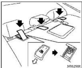
Diagram showing car seatbelt mechanism with directional arrows and a device labeled JV0258XToptetheranchorpointlocations Anchorpointsarelocatedontherear parcelshelf. If you have any questions when installing atoptetherstrapchildrestraint on the rearseal, consult an INFINITretailer for details.
adultseatbelts, or other items are equipment to the vehicle. Doings could damage the child restraint anchorages. The child restraint will not be properly installed using the damaged anchorage, and a child could be seriously injured or killed in a collision.
REAR-FACINGCHILDRESTRAINTIN- STALLATIONUSINGLATCH
RefertoallWarningsandCautionsinthe "Child safety" and "Child restraints" sectionsbeforeinstallingachildrestraint.
Followthesestepstoinstallarear-facing childrestraintusingtheLATCHsystem:
- Position the child restraint on these seat. Always follow the child restraint manufacturer's instructions.
natural_image
Diagram of a car seat assembly with an inset showing a detail of the component (no text or symbols present)Rear-facingweb-mounted—step2
- Secure the child restraint anchor attachment stotheLATCHlower anchors. Check to make sure the LATCH attachment is properly attached to the lower anchors.

WARNING
Childrestraintanchoragesaredesignedto withstandonlythoseloadsimposedby correctlyfittedchildrestraints.Underno circumstancesaretheytobeusedtoattach
Safety — Seats, seat belts and supplemental restraint system
text_image
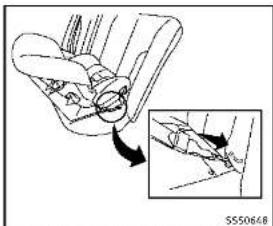
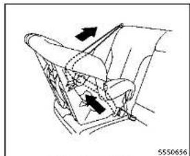
Diagram showing car wheel assembly with labeled components and directional arrows indicating motion or movementRear-facingrigid-mounted-step2
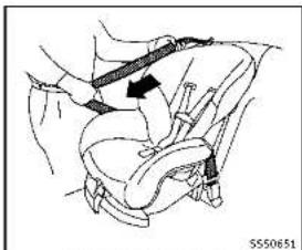
- For children restraints that are equipped with webbing-mounted attachments, remove any additional slack from the anchor attachments. Pressdownward and rearward firmly in the center of the child restraint with your hand to compress the vehicle seat cushion and seat back while tightening the webbing of the anchor attachments.

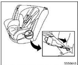
natural_image
Line drawing of a person seated in a car seatbelt, no text or symbols presentRear-facing-step4
natural_image
Diagram showing hands using a tool to adjust or install a car interior (no text or symbols visible)Rear-facing—step3

Safety — Seats, seat belts and supplemental restraint system
applicable). Not all child restraints fit in all types of vehicles.
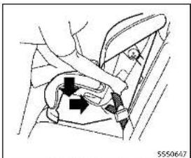
- Checktomakesurethechildrestraint is properly secured prior to each use. If the child restraint is loose, repeat steps 1 through 4.

natural_image
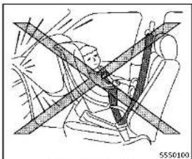
Diagram of a car seatbelt with diagonal lines indicating safety or comfort (no text or symbols)REAR-FACINGCHILDRESTRAINTIN- STALLATIONUSINGTHESEATBELTS
WARNING
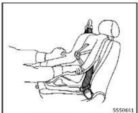
■Thethree-pointseatbeltwithAutomatic LockingRetractor(ALR)mustbeused wheninstallingachildrestraint.Failure tousetheALRmodewilresultinthe childrestraintnotbeingproperlysecured. The restraint could tip over or be loose and cause injury to a child in a sudden stop or collision. Also, it can change the operation of the front pas-
sengerairbag.See"Frontpassengerair bagandstatuslight"(P.1-49).
- Wheninstallingachildrestraintsystem intherearcenterposition,boththe centerseatbeltconnectortongue and buckletongue mustbesecured(for modelswith rearseatfolding). See "Rearcenterseatbelt(modelswithrear seatfolding)"(P.1-18).
natural_image
Diagram of a car seatbelt with diagonal bands indicating safety or comfort (no text or symbols)Rear-facing—step1
RefertoallWarningsandCautionsinthe "Child safety" (P.1-22) and "Child restraints"(P.1-24) beforeinstallingachild restraint.
Followtheseslepsloinstallarear-facing childrestraintusingthevehicleseatbelts intherearseats:
- Childrestraintsforinfantsmustbe usedintherear-facingdirectionand thereforemustnotbeusedinthefront seat.Positionthechildrestraintonthe seat.Alwaysfollowtherestraintmanufacturer'sinstructions.
natural_image
Technical line drawing of a mechanical assembly with no visible text or symbolsRear-facing-step2
- Routetheseatbeltonguethroughthe childrestraintandinsertitintothe buckleuntilyouhearandfeelthelatch engage.Besuretofollowthechild restraintmanufacturer'sinstructions forbeltrouting.
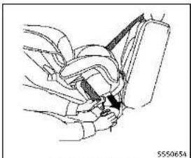
natural_image
Line drawing of a car seatbelt mechanism (no text or symbols)Rear-facing-step3
3.Pulltheshoulderbeltuntilthebeltis fullyextended.Atthistime,theseat beltretractorisintheAutomaticLockingRetractor(ALR)mode(childrestraint mode).ItrevertstotheEmergency LockingRetractor(ELR)modewhen theseatbeltisfullyretracted.

Safety — Seats, seat belts and supplemental restraint system
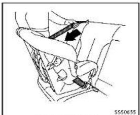
natural_image
Diagram of a car interior showing directional arrows and a valve mechanism (no text or symbols)Rear-facing-step4
4. Allow these seatbeltoretract. Pull upon the shoulder belt to remove anyslack in the belt.

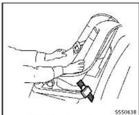
natural_image
Diagram of a car interior showing hand positioning and valve mechanism (no text or symbols)

natural_image
Line drawing of a car seatbelt with arrows indicating left and right motion (no text or symbols)Rear-facing-step6
6. After attaching the childrestraint, test it before you place the childinit. Push if fromsidetosidewilholding the childrestraint near these seat belt path. The childrestraint should not move more than 1 inch (25mm), fromsideto side. Try to get it forward and check to see if the belthold stherrestraint in place. If thereerstraint is not secure, tightenthesate belts necessary, or put their restraint in another seat and testitagain. You may need to try a different childrestraint. Not all child restraints fit all types of vehicles.
- Checktomakesurethatthechild restraintisproperlysecuredpriorto eachuse.Iftheseatbeltisnotlocked, repeatsteps1through6.
After the child restraint is removed and the seat belt fully retracted, the AL Rmode (child restraint mode) is canceled.
FORWARD-FACINGCHILDRESTRAINT INSTALLATIONUSINGLATCH
RefertoallWarningsandCautionsinthe "Child safety" and "Child restraints" sectionsbeforeinstallingachildrestraint.
Followthesestepstoinstallaforward-facingchildrestraintusingtheLATCH system:
- Position the child restraint on these seat. Always follow the child restraint manufacturer's instructions.
text_image
Diagram illustrating car seatbelt usage with magnified detail showing hand positioning and weight measurementForward-facingweb-mounted—step2
2.Securethechildrestraintanchorat-
tachmentstotheLATCHloweranchors.
ChecktomakesuretheLATCHattach-
mentisproperlyattachedtothelower
anchors.
If the child restraint is equipped with
toptetherstrap, routethetoptether
strapandsecurethetetherstraptothe
tetheranchorpoint.See"Installingtop telbersIran"(R 1-38) Danetinstall
tetherstrap (P.1-58).Donotinstall child restraints that require the use of a
Lima restraints that require the use of a top tether strap in seating positions
that do not have a top tether anchor.

text_image
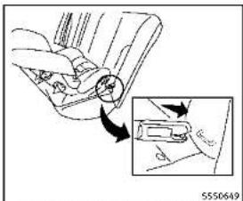
5550646Forward-facingrigid-mounted-step2
- The back of the child restraint should be secured against the vehicle seat-back.
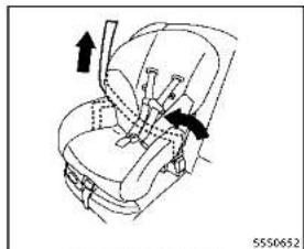
Ifnecessary,adjustorremovethehead restrainttoobtainthecorrectchild restraintfit.Iftheheadrestraintis removed,storeitinasecureplace.Be suretoreinstalltheheadrestraint whenthechildrestraintisremoved. See"Headrestraints/headrests"(P.1-8) forheadrestraintadjustmentinformation.
If theseatingpositiondoesnothavean adjustableheadrestraintanditis interferingwiththeproperchildrestraintfit,tryanotherseatingposition oradifferentchildrestraint.
natural_image
Mechanical diagram showing a car seatbelt with directional arrows indicating rotation (no text or symbols)Forward-facing—step4
-
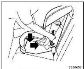
For child restraint sthat are equipped with webbing-mounted attachments, remove any additional slack from the anchor attachments. Press downward and rearward firmly in the center of the child restraint with your kneetocompress the vehicle seat cushion and seat back while tightening the webbing of an anchor attachments.
-
Tightentheletherstrapaccording to the manufacturer's instructions to remove any slack.

natural_image
Line drawing of a hand adjusting a car seatbelt (no text or symbols)Forward-facing—step6
-
After attaching the childrestraint, test itbeforeyouplacethechildinit.Pushfromsidetosidewhileholdingthe childrestrainteartheLATCHattach-mentpath. The childrestraint should notmovemorethan1inch(25mm), fromsidetoside.Trytotugitforward andcheckloseeiltheLATCHattach-mentholdstherestraintinplace.Ifthe restraintisnotsecure,tightenthe LATCHattachmentsnecessary, or puttherestraintinanoetherseatand testitagain.Youmayneetotrya differentchildrestraint.Notalchild restraintsfitinaltypesofvehicles.
-
Checktomakesurethechildrestraint is properly secured prior to each use. If the child restraint is loose, repeat steps 1 through 6.
FORWARD-FACINGCHILDRESTRAINT INSTALLATIONUSINGTHESEAT BELTS

WARNING
- The three-point seat belt with Automatic Locking Retractor (ALR) must be used when installing a child restraint. Failure tous the ALR mode will result in the child restraint not being properly secured. There strain could tip over be loose and cause injury to a child in sudden stop or collision. Also, it can chan gethe operation of the front passenger air bag. See "Front passenger air bag and status light" (P.1-49).
- Wheninstallingachildrestraintsystem intherearcenterposition,boththe centerseatbeltconnectortongueand buckletonguemustbesecured(for modelswithrearseatfolding).See "Rearcenterseatbelt(modelswithrear
seatfolding)"(P.1-18).

natural_image
Line drawing of a car interior showing seat, dashboard, and rear seats with an arrow indicating direction (no text or symbols)Forward-facing(frontpassengerseat)
RefertoallWarningsandCautionsinthe "Child safety" and "Child restraints" sectionsbeforeinstallingachildrestraint. Followthesestepstoinstallaforward-facingchildrestraintusingthevehicleseat beltintherearseatsorinthefront passengerseat:
- If you must install child restraint in the front seat, it should be placed in forward-facing direction only. Move the seat to there are most position. Child restraints for infants must be used in therear-facing direction and, therefore, must not be used in the front seat.
Safety - Seats, seat belts and supplemental restraint system 1-35
- Position the child restraint on these seat. Always follow the child restraint manufacturer's instructions. The back of the child restraint should be secured against the vehicle seat back.
If necessary, adjustorremovethehead restraintorheadresttoobtainthe correctchildrestraintfit.If thehead restraintorheadrestisremoved, store itinasecureplace. Besuretoreinstall theheadrestraintorheadrestwhen thechildrenstreantisremoved.See "Headrestraints/headrests"(P.1-8)for headrestraintorheadrestadjustment, removalandinstallationinformation.
If theseating position does not have an adjustable head restraint or head rest and is interfering with the proper child restraint, try another seating position or different child restraint.
natural_image
Mechanical diagram showing a belt buckle being inserted into a car seat (no text or symbols visible)Forward-facing-step3
- Routetheseatbeltonguethroughthe childrestraintandinsertitintothe buckleuntilyouhearandfeelthelatch engage.Besuretofollowthechild restraintmanufacturer'sinstructions forbeltrouting.
If the child restraint is equipped with toptether strap, routethetoptether strap and secure the tether strap tothe tether anchorpoint (rearseal installation only). See "Installing top tether strap" (P.1-38). Do not install child restraints that require the use of a top tether strap in seating positions that do not have a top tether anchor.
natural_image
Medical illustration showing a hand holding a catheter inserted into a seated car seat (no text or symbols present)Forward-facing—step4
- Pulltheshoulderbeltuntilthebeltis fullyextended.Atthistime,theseat beltretractorisintheAutomaticLockingRetractor(ALR)mode(childrestraint mode).ItrevertstoEmergencyLocking Retractor(ELR)modewhenteseatbelt isfullyretracted.
natural_image
Line drawing of a car seat with a belt buckle and arrow indicating direction (no text or symbols)Forward-facing-step5
5. Allow these seatbeltoretract. Pull upon the shoulder belt to remove any slack in the belt.
natural_image
Diagram of a car seatbelt buckle with arrows indicating direction (no text or symbols)
Forward-facing—step6
6. Remove any additional slack from the seatbelt; press downward and rearward firmly in the center of the child restraint with your kneet to compress the vehicle seat cushion and seatback while pulling up on these seat belt.
7. Tightenthetetherstrapaccording to the manufacturer's instruction store-moveanyslack.
natural_image
Line drawing of a car seatbelt with hand placement, no text or symbols presentForward-facing—step8
8. After attaching the childrestraint, test it before you place the childinit. Push if fromsidetosidewilheholding the childrestraint near these seat belt path. The childrestraint should not move more than 1 inch (25mm), fromsideto side. Try to get it forward and check to see if the belthold stherrestraint in place. If thereerstraint is not secure, tightenthesate belts necessary, or put their restraint in another seat and testitagain. You may need to try a different childrestraint. Not all child restraints fit all types of vehicles.
- Checktomakesurethechildrestraint is properly secured prior to each use. If these at belt is not locked, repeat steps 2 through 8.
text_image
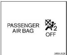
PASSENGER AIR BAG OFF [VR0192X]Forward-facing—step10
- If the child restraint is installed in the front passenger seat, place the ignition switch in the ON position. The front passenger air bag status light should illuminate. If this light is not illuminated, see "Front passenger air bag and status light" (P. 1-49). Move the child restraint to another sea seating position. Haveth system checked by an INFINIT retailer.
After the child restraint is removed and the seat belt is fully retracted, the ALR mode (child restraint mode) is canceled.

text_image
Diagram showing car seatbelt and door panel with directional arrows indicating movement or movementINSTALLINGTOPTETHERSTRAP
WARNING
Childrestraintanchoragesaredesignedto withstandonlythoseloadimposedby correctlyfittedchildrestraints. Underno circumstancesaretheytobeusedtoattach adultseatbelts,rootheritemsorequipmenttothevehicle.Doingsocoulddamage thechildrestraintanchorages.Thechild restraintwillnotbeproperlyinstalledusing thedamagedanchorage,andachildcould beseriouslyinjuredorkilledinacollision.
First, secure the child restraint with the LATCH lower anchors (rearout board seat positions only) or these seat belt, as applicable.
-
Flipuptheanchorcoverfromthe anchorpointwhichislocateddirectly behindthechildseat.
-
If necessary, raise or remove the head restraintor head rest to position the top tether strap over the top of these seat-back. If the head restraintor head rest is removed, store it in a secure place. Besuretore install the head restraintor head rest when the child restraint is removed.
See "Headrestraints/headrests"(P.1-8)forheadrestraintorheadrest adjustment,removalandinstallation information. Positionthetoptetherstrapoverthe topoftheseatback.
-
Securethetetherstraptothetether anchorpointontherearparcelshelf.
-
Refertotheappropriatechildrestraint installationprocedurestepsinthis sectionbeforetighteningtheether strap.
If you have any questions when installing atoptetherstrap, consult your INFINITE retailer for details.
BOOSTERSEATS
Precautionsonboosterseats
WARNING
Ifaboosterseatandseatbeltarenotused properly,theriskofachildbeinginjuredin asuddenstoporcollisiongreatlyincreases:
•Makesuretheshoulderportionofthe beltisawayfromthechild'sfaceand neckandthelapportionofthebeltdoes notcrossthestomach.
- Makesuretheshoulderbeltisnot behindthechildorunderthechild's arm.
■Aboosterseatmustonlybeinstalledin aseatingpositionthathasalap/shoulderbelt.
natural_image
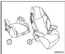
Line drawing of two car seats with numbered labels (1 and 2), no text or symbols present.Boosterseatsofvarioussizesareoffered byseveralmanufacturers.Whenselecting anyboosterseat,keepthefollowingpoints inmind:
- Chooseonlyaboosterseatwithalabel certifyingthatitcomplieswithFederal MotorVehicleSafetyStandard213or CanadianMotorVehicleSafetyStandard213.
- Checktheboosterseatinyourvehicle tobesureitiscompatiblewiththe vehicle'sseatandseatbeltsystem.

Safety — Seats, seat belts and supplemental restraint system
natural_image
Illustration of a person sitting on a chair with crossed arms, no text or symbols present■ Makesurethechild'sheadwillbe properlysupportedbytheboosterseat orvehicleseat. Theseatbackmustbeat orabovethecenterofthechild'sears. Forexample,ifalowbackboosterseat ① ischosen,thevehicleseatback mustbeatorabovethecenterofthe child'sears.Iftheseatbackislower thanthecenterofthechild'sears,a highbackboosterseat ② shouldbe used.
natural_image
Line drawing of a person sitting in a car seat, wearing a vest (no text or symbols)- If the booster seat is compatible with your vehicle, place your child in the booster seat and check the various adjustment to be sure the booster seat is compatible with your child. Always follow all recommended procedures.
AllU.S. states and Canadian provinces or territories require that infants and small children berestrained in an approved child restraint at all times while the vehicle is being operated.
The instructions in this section apply to booster seat installation in the rear seats orthefro of passenger seat.
Boosterseatinstallation
CAUTION
Donotusethelap/shoulderbeltAutomatic LockingRetractor(ALR)modewhenusinga boosterseatwiththeseatbelts.
RefertoallWarningsandCautionsinthe "Child safety", "Child restraints" and "Booster seats" sections earlier in this sectionbeforeinstallingachildrestraint. Followthesestepstoinstallaboosterseat intherearseatorinthefrontpassenger seat:

natural_image
Line drawing of a car interior showing seat, rearview mirror, and side door (no text or symbols)- If you must install a booster seat in the front seat, movethese at to there are most position.
- Positiontheboosterseatontheseat. Onlyplaceitinaforward-facingdirection. Alwaysfollowtheboosterseat manufacturer'sinstructions.
natural_image
Line drawing of a person wearing a seatbelt and holding a belt, seated in a car (no text or symbols)Frontpassengerposition
3. The booster seat should be positioned on the vehicle seat so that it is stable.
If necessary, adjust or remove the head restraint or head rest to obtain the correct booster seat if the head restraint or head rest is removed, store it in secure place. Besuretore install the head restraint or head rest when the booster seat is removed. See "Head restraints/headrests" (P.1-8) for head restraint or head rest adjustment, removal and installation information.
If the seating position does not have an adjustable head restraint or head rest
anditisinterferingwiththeproper boosterseatfit,tryanotherseating positionoradifferentboosterseat.
4. Positionthelapportionoftheseatbelt lowandsnugonthechild'ships. Be suretofollowtheboosterseatmanufacturer'sinstructionsforadjustingthe seatbeltrouting.
5. Pulltheshoulderbeltportionofthe seatbelttowardtherextractortotakeup extraslack. Besuretheshoulderbeltis positionedacrossthetop, middleportionofthechild'sshoulder. Besureto followtheboosterseatmanufacturer's instructionsforadjustingtheseatbelt routing.
6. Followthewarnings, cautions and instructions for properly fasteninga seatbelt shown in "Seatbelts" (P.1-12).
PASSENGER AIR BAG

JVR0192X
- If the booster seat is installed in the front passenger seat, push the ignition switch to the ON position. The front passenger air bag status light may or may not illuminated depending on the sizeof child and the type of booster seat used. See "Front passenger air bag and status light" (P.1-49).
SUPPLEMENTALRESTRAINTSYSTEM
PRECAUTIONSONSUPPLEMENTAL RESTRAINTSYSTEM
This Supplemental Restraint System(SRS) section contains important information concerning the following systems:
- Driverandpassengerfront-impactsupplementalairbags(INFINITIAvanced AirBagSystem)
- Frontseat-mountedside-impactsupplementalairbag
■Roof-mountedcurtainside-impactsupplementalairbag
- Seatbeltwithpretensioner Supplementalfront-impactairbagsystem: TheINFINITIAadvancedAirBagSystemcan helpcushiontheimpactforcetothehead andchestofthedriverandfrontpassenger incertainfrontalcollisions.
Frontseat-mountedside-impactsupplementalairbagsystem:Thissystemcan helpcushiontheimpactforcetothechest andpelvisareaofthedriverandfront passengerincertainsideimpactcollisions. Thesideairbagisdesignedtoinflateon the side where the vehicle is impacted.
Roof-mounted curtain side-impact supplemental air bag system: This system can help cushion the impact force to the head
ofoccupantsinfrontandrearoutboard seatingpositionsincertainsideimpact collisions. Thecurtainairbagsarede-signedtoinflateonthesidewherethe vehicleisimpacted.
Thesesupplementalrestraintsystemsare designedtosupplementthecrashprotectionprovidedbythedriverandpassenger seatbeltsandarenotasubstitutefor them.Seatbeltsshouldalwaysbecorrectlywomandtheoccupantseateda suitabledistanceawayfromthesteering wheel,instrumentpanelandoorfinishers. (See "Seat belts" (P.1-12) for instructionsandprecautionsonseatbelt usage.)
Thesupplementalairbagsoperateonly whentheignitionswitchisintheON position.
AfterpushingtheignitionswitchtotheON position,thesupplementalairbagwarninglightilluminates.Thesupplementalair bagwarninglightwillturnoffafterabout 7secondsifthesystemsareoperational.

WARNING
- Thefrontairbagsordinarilywillnot Inflatelntheeventofasideimpact, rear Impact, rollover, orlowerseverityfrontal collision. Alwayswearyourseatbeltsto helpreducetheriskorseverityofinjury invariouskindsofaccidents.
●Thefrontpassengerairbagwillnot inflateifthepassengerairbagstatus lightislitorifthefrontpassengerseat isunoccupied.See"Frontpassengerair bagandstatuslight"(P.1-49).
Theseatbeltsandthefrontairbagsare most effective when you are sitting well back and upright in these at with both feet the floor. The frontairbags inflate with great force. Even with the INFINI Advanced air bags system, if you are unrestrained, leaning forward, sittingsdays or out of position in any way, you are greater risk of injury death in acrash. You may also receive serious or fatal injuries from the frontair bag if you are up again sit with them inflates. Always still back against the seatback and as far away as practical from the steering wheel or instrument
panel.Alwaysusetheseatbelts.
- The driver and front passenger seat belt buckles are equipped with sensor that detect if these seat belts are fastened. The Advanced Air Bag System monitor the severity of collision and seat belt usage in Inflatest air bags as needed. Failure to properly wear seat belts can increase risk severity of injury in an accident.
•Thefrontpassengerseatisequipped withoccupantclassificationsensors (weightsensors)thatturnthefront passengerairbagOFFundersome conditions.Thesesensorsareonlyused inthisseat.Failuretobeproperlyseated andwearingtheseatbeltcanincrease theriskorseverityofinjuryinan accident.See"Frontpassengerairbag andstatuslight"(P.1-49).
- Keephandsontheoutsideofthe steeringwheel.Placingtheminsidethe steeringwheelrimcouldincreasethe riskofinjuryifthefrontairbaginflates.
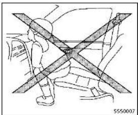
natural_image
Diagram of a person standing with crossed bars, no text or symbols present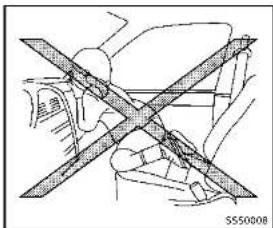
natural_image
Diagram of a car wheelbelt with diagonal crossed lines indicating no movement or force (no text or symbols present)
natural_image
Diagram of a person crossed with a diagonal line, showing mechanical or safety constraints (no text or symbols present)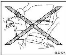
natural_image
Diagram of a car seatbelt with diagonal band crossing (no text or symbols)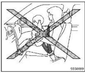
natural_image
Diagram of a car seatbelt with diagonal crossed bars indicating no text or symbols (no readable text or labels)
natural_image
Diagram of a car seatbelt with diagonal lines indicating safety or clearance zones (no text or symbols present)WARNING
- Neverletchildrenrideunrestrainedor extendtheirhandsorfaceoutofthe window.Donotattempttoholdtheminyourlaporarms.Someexamplesof dangerousridingpositionsareshownin theillustrations.
•Childrenmaybeseverelyinjuredor killedwhenthefrontairbags,sideair bagsorcurtainalrbagsinflatelfthey arenotproperlyrestrained.Pre-teens andchildrenshouldbeproperlyrestrainedintherearseat,ifpossible. - EvenwiththeINFINITIAadvancedAirBag System,neverinstallarear-facingchild restraintinthefrontseat.Aninflating frontairbagcouldseriouslyinjureorkill yourchild.See"Childrestraints"(P.1-24)fordetails.
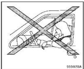
natural_image
Diagram of a vehicle with crossed diagonal lines indicating no change or restriction (no text or symbols present)
natural_image
Diagram of a car with a cross-shaped barrier symbol crossed out, no text or labels present
Safety — Seats, seat belts and supplemental restraint system
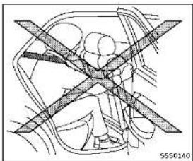
natural_image
Diagram of a car interior showing steering wheel and dashboard (no text or labels)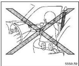
natural_image
Diagram of a person wearing a helmet crossed out by a diagonal line, no text or symbols present
natural_image
Interior view of a car showing a person seated with a cross-shaped object on the seat (no text or symbols visible)WARNING
Frontseat-mountedside-impactsupplementalairbagsandroof-mountedcurtainside-impactsupplementalairbags:
- Thesideairbagsandcurtainairbags ordinarilywillnotinflateintheeventof afrontalimpact,rearImpact,rolloveror lowerseveritysidecollision.Always wear your seat belts to help reduce the risk or severity of injury in various kinds ofac cidents.
• The seat belts, side air bags and curtain
airbagsaremosteffectivelywhenyouare sittingwellbackanduprightintheseat. Thesideairbagandcurtainalirbag inflatewithgreatforce. Donotallow anyonetoplacetheirhand,legorface nearthesideairbagonthesideothe seatbackofthefrontseatomearthe siderofrails. Donotallowanyone sittinginthefrontseatsorrearoutboard seatstoextendtheirhandoutofthe windoworleanagainsthedoor. Some examplesofdangerousridingpositions areshowninthepreviousillustrations.
-Whensittingintherearseat,donot holdontotheseatbackofthefrontseat. Ifthesupplementalsideairbaginflates, youmaybeseriouslyinjured.Beespeciallycarefulwithchildren,whoshould alwaysbeproperlyrestrained.Some examplesofdangerousridingpositions areshownintheillustrations.
- Donotuseseatcoversonthefront seatbacks. They may interferewithside airbaginflation.
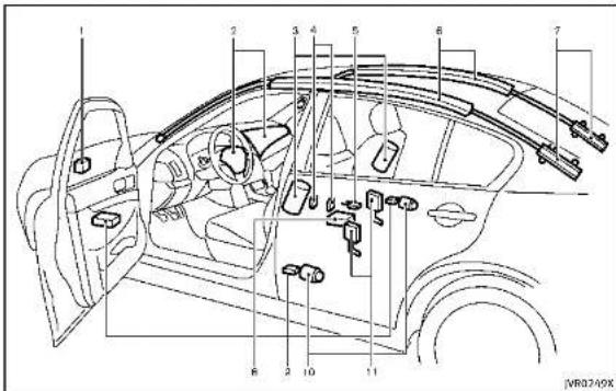
text_image
Technical diagram of a car interior with numbered components for identification1.Crashzonesensor
2. Supplementalfrontairbagmodules (INFINITIAdvancedAirBags)
3. Frontseat-mountedside-impactsupplementalairbags
4. Occupant classification sensors (weightsensors)
5. Occupantclassificationsystemcontrolunit
6. Roof-mounted curtainside-impact supplemental air bags
7. Roof-mounted curtain side-impact supplemental air bag inflators
8.AirbagControlUnit(ACU)
9.Satellitesensors
10.Seatbeltswithpretensioners
11.Lapouterpretensioners
INFINITIADVANCEDAIRBAGSYS-TEM(frontseats)

WARNING
Toensureproperoperationofthepassenger'sadvancedairbagsystem,please observethefollowingitems.
- Donotallowapassengerintherearseat topushorpullontheseatbackpocket.
- Donotplaceheavyloadsheavierthan, lbs.(4kg)ontheseatback,head restraintorintheseatbackpocket.
- Donotstoreluggagebehindtheseat thatcanpressintotheseatback.
- Confirm the operating condition with the front passenger air bag status light.
- If you notice that the front passenger air bag status light is not operating in accordance with the aboved description, please take your vehicle to your INFINIT retail to check the passenger seat advanced air bagsystem.
- Until you have confirmed with your retailer that your passenger seat advanced air bag is working properly, position the occupants in there are seating positions.
This vehicle is equipped with the INFINITI Advanced Air Bag System for the river and front passenger seats. This system is designed to meet certification requirements under U.S. regulations. It is also permitted in Canada. However, all of the information, cautions and warnings in this manual still apply and must be followed.
The driversupressmentalfront-impactair bagislocatedinthecenterofthesteering wheel. The frontpassengersupplemental front-impactairbagosettedinthe instrumentpanelabovetheglovebox. The frontairbagsaredesignedtoinflatein higherseverityfrontalcollisions, although theymayinflateiftheforcesinanother typeofcollisionsaresimilartothoseofa higherseverityfrontalimpact. Theymay notinflateincertainfrontalcollisions. Vehicledamage(orlackofit)isnotalways anindicationofproperfrontairbag operation.
TheINFINITIAadvancedAirBagSystemhas
dualstageairbaginflators. Thesystem monitorsinformationfromthecrashzone sensor,theAirbagControlUnit(ACU),seat beltbuckleswitchesandtheoccupant classificationsensors(weightsensors). Inflatoroperationisbasedontheseverity ofacollisionandseatbeltusageforthe driver. Forthefrontpassenger, theoccupantclassificationsensorsarealsomonitored. BasedonInformationfromthe sensors,onlyonefrontairbagmayinflate inacrash,dependingonthecrashseverity andwhetherthefrontoccupantsarebelted orunbelted. Additionally,thefrontpassengerairbagmaybeautomaticallyturned OFFundersomeconditions,depending on theinformationprovidedbytheoccupant classificationsensors. IfthefrontpassengerairbagisOFF,thepassengerairbag statuslightwillbeilluminated(iftheseat isunoccupied,thelightwillnotbe illuminated,buttheairbagwillbeoff). (See"frontpassengerairbagandstatus light"(P.1-49)forfurtherdetails.)Onefront airbaginflatingdoesnotindicateimproper performance of the system.
If you have any questions about your air bag system, contact an INFINITI retailer. If you are considering modification of your vehicleduetoadisability,youmayalso contactanINFINITlretailer.Contactinformationiscontainedinthefrontofthis Owner'sManual.
Whenafrontairbaginflates,afairlyloud noisemaybeheard,followedbyreleaseof smoke. Thissmokeisnotharmfulanddoes notindicateafire.Careshouldbetaken nottoinhaleit,asitmaycauseirritation andchoking.Thosewithahistoryofa breathingconditionshouldgetfreshair promptly.
Frontairbags, alongwiththeuseofseat belts, helptocushiontheimpactforceon theheadandchestofthefrontoccupants. Theycanhelpsavelivesandreduce seriousinjuries. However, aninflatingfront airbagmaycausefacialabrasionsorother injuries. Frontairbagsdonotprovide restrainttothelowerbody.
EvenwithINFINITadvancedairbags,seat beltsshouldbecorrectlywornandthe driverandpassengerseateduprightasfar aspracticalawayfromthesteeringwheel orinstrumentpanel.Thefrontairbags inflatequicklyinordertohelpprotectthe frontoccupants.Becauseofthis,theforce ofthefrontairbaginflatingcanincrease theriskofinjurylftheoccupantistoo
closeto, orisagainst, theairbagmodule duringinflation.
Thefrontairbagsdeflatequicklyaftera collision.
Thefrontairbagsoperateonlywhenthe ignitionswitchisintheONposition.
AfterpushingtheignitionswitchtotheON position,thesupplementalairbagwarninglightilluminates.Thesupplementalair bagwarninglightwillturnoffafterabout 7secondsifthesystemisoperational.
PASSENGER AIR BAG

NR0192X
Frontpassengerairbagandstatus light
WARNING
Thefrontpassengerairbagisdesignedto automaticallyturnOFFundersomeconditions. Readthissectioncarefullytolearn howitoperates. Properuseoftheseat, seat beltandchildrestraintsisnecessaryfor most effective protection. Failure to follow all instructions in this manual concerning the use of seats, seat belts and child restraints can increase the risk or severity
ofinjuryinanaccident.
Statuslight:
Thefrontpassengerairbagstatuslight islocatedontheinstrumentpanel. AftertheignitionswitchisplacedintheON position, thefrontpassengerairbagstatus lightilluminatesforabout7secondsand thenturnsofforilluminatesdependingon thefrontpassengerseatoccupiedstatus. Thelightoperatesasfollows:
●Unoccupiedpassengerseat:The OFFandthefrontpassengerairbagis is OFFandwillnotinflateinarrash
●Passengerseatoccupiedbyasmall adult,childorchildrestraintasoutlinedinthissection:The illuminates to indicate that the front passengerairbagisOFFandwillnot inflateinacrash.
Occupiedpassengerseatandthepassengermeetstheconditionsoutlinedin thissection:Thelight isOFFto indicate that the front passenger air bagisoperational.
Frontpassengerairbag: Thefrontpassengerairbagisdesignedto automaticallyturnOFFwhenthevehicleis
Safety - Seats, seat belts and supplemental restraint system 1-49
operated undersome conditions as described below as permitted by U.S. regulations. If the front passenger air bag is OFF, it will not inflate in a crash. The driver air bag and other air bags in your vehicle are not part of this system.
The purpose of the regulation is to help reduce risk of injury or death from an inflating airbag to certain front passenger seat occupants, such as children, by requiring the airbag to be automatically turned off.
The occupant classification sensors (weightsensors) are on these at cushion frame under the front passenger seat and are designed to detect an occupant and object on these. For example, if a child is in the front passenger seat, the Advanced Air Bag System is designed to turn the passenger air bag Off in accordance with the regulations. Also, if a child restraint of the types specified in the regulations is on these, the occupant classification sensors can detect it and cause the air bag to turn OFF.
Frontpassengerseatadultoccupantswho areproperlyseatedandusingtheseatbelt asoutlinedinthismanualshouldnot causethepassengerairbagtobeauto-
maticallytymedOFF. Forsmalladultsit may be returnedOFF, however, if the occupant does not sit in theseat properly (forexample, bynotsittingupright, by sittingonanedgeoftheseat, orby otherwise being out of position), this could cause the sense to turn their airbag OFF. Always besuretobeseated and wearing these at belt properly for them most effective protection by these at belt and supplement alairbag.
INFINITirecommendsthatpre-teensand childrenbeproperlyestrainedinear eat.INFINITIalsorecommendsthatappro- priatechildrestraintsandboosterseatsbe properlyinstalledinarearseat.lithisis notpossible.theoccupantclassification sensorsaredesignedtooperateasde- scribedabovetoturnthefrontpassenger airbagOFFforspecifiedchildrestraints. Fallingtoproperlysecurechildrestraints andtousetheALRmode(childrestraint mode)mayallowtherestrainttotipor moveinanaccidentorsuddenstop.This canalsoresultinthepassengeralirbag inflating in a crash instead of being OFF. (See "Child restraints" (P.1-24) for proper useand installation.)
If the front passenger seat is not occupied, thepassengerairbagisdesignednotto inflateinacrash. However, heavyobjects placedontheseatcouldresultinairbag inflation, becauseoftheobjectbeing detectedbytheoccupantclassification sensor. Otherconditionscouldalsoresult inairbaginflation, suchasifachildis standingontheseat, oriftwochildrenare ontheseat,contrarytotheinstructionsin thismanual. Alwaysbesurethatyouand allvehicleoccupantsareseatedand restrainedproperly.
Using the passenger air bag status light, you can monitor when the front passenger air bag is automatically turned OFF with the seat occupied. The light will not illuminate when the front passenger seat is unoccupied.
Ifanadultoccupantisintheseatbutthe passengerairbagstatuslightisilluminated(indicatingthattheairbagisOFF),it couldbethatthepersonisasmalladult, orisnotsittingontheseatproperly.
Ifachildrestraint must be used in the front seat, the passenger airbagstatuslight may form not be illuminated, depending on the size of the child and the type of child restraint being used. If the passenger airbagstatuslight is not illuminated
(indicatingthattheairbagmightinflatein acrash), it could be that the child restraint or seat belits not being used properly. Makesure that the child restraint is installed properly, these belt is used properly and the occupant is positioned properly. If the passenger air bag status light is still illuminated, reposition the occupant or child restraint in are seat. If the passenger air bag status light will not illuminate event though you believe that the child restraint, these belts and the occupant are properly positioned, the system may besensing an unoccupied seat (in which case the air bag is OFF). Your INFINIT retailer can check that the system is Off by using a special tool. However, until you have confirmed with your retailer that your air bag is working properly, reposition the occupant or child restraint in are seat.
TheINFINITIAvancedAirBagSystemand passengerairbagstatuslightwilltakea fewsecondstoregisterachangeinthe passengerseatstatus.However,iftheseat becomesunoccupied,theairbagstatus lightwillremainoff.
Ifamalfunctionoccursinthefront passengerairbagsystem,thesupplemen-
talairbagwarninglight ,locatedinthe meterandgaugesareawillblink.Havethe systemcheckedbyanINFINITretailer.
Othersupplementalfront-impact airbagprecautions

WARNING
- Donotplaceanyobjectsonthesteering wheelpadorontheinstrumentpanel. Also, donotplaceanyobjectsbetween anyoccupantandthesteeringwheel or instrumentpanel. Suchobjectsmay became dangerousprojectilesandcause injurylfthefrontairbagsinflate.
- Donotplaceobjectswithsharpedges ontheseat. Also, donotplaceheavy objectsontheseatthatwillleave permanentimpressionsintheseat. Such objectscandamagetheseatoroccupant classificationsensors(weightsensors). This can affect the operation of the air bagsystemandresult in serious personal injury.
- Do not use water or acidic cleaners (hot steam cleaners) on the seat. This can damage the seat or occupant classification sensors. This can also affect the
operationoftheairbagsystemand resultinseriouspersonalinjury.
- Immediatelyafterinflation,severalfront airbagsystemcomponentswillbehot. Donottouchthem;youmayseverely burnyourself.
- Nounauthorizedchangesshouldbe madetoanycomponentsorwiringof theairbagsystem. This is to prevent accidental inflation of the supplemental airbagordamagetothesupplemental airbagsystem.
- Donotmakeunauthorizedchangesto yourvehicle'selectricalsystem, suspensionsystemorfrontendstructure. This could affect properoperationofthefront airbagsystem.
- Tamperingwiththeairbagsystemmay resultinseriouspersonalinjury.Tamperingincludeschangestothesteering wheelandtheinstrumentpanelassemblybyplacingmaterialoverthesteering wheelpadandabovetheinstrument panelorbyinstallingadditionalaltrim materialaroundtheairbagsystem.
-Removingormodifyingthefrontpassengerseatmayaffectthefunctionof theairbagsystemandresultinserious
personalinjury.
• Modifyingortamperingwiththefront passengerseatmayresultinserious personalinjury. Forexample, donot changethefrontseatsbyplacing materialontheseatcushionorby installingadditionalatrimaterial,such asseatcovers,ontheseathalisnot specificallydesignedtoassureproper airbagoperation.Additionally,donot stowanyobjectsunderthefrontpassengerseatortheseatkushionand seatback.Suzuchjectsmayinterfere withtheproperoperationtheoccupantclassificationsensors.
• Nounauthorizedchangesshouldbe madetoanycomponentsorwiringof theseatbeltsystem. This may affect the frontairbagsystem. Tampering with the seatbeltsystem may result in serious personal injury.
•Workonandaroundthefrontairbag systemshouldbedonebyanINFINITI retailer.Installationofelectricaltequipments should alsobedonebyanINFINITI retailer.The Supplemental Restraint System(SRS)wiring harnesses*should notbemodifiedordisconnected.Unauthorizedelectricaltestequipment and
probingdevicesshouldnotbeusedon theairbagsystem.
- Acrackedwindshieldshouldbereplaced immediatelybyaqualifiedrepairfacility. Acrackedwindshieldcouldaffectthe functionofthesupplementalairbag system.
*The SRSwiringharnessconnectors are yellow and orange foreasy identification.
Whensellingyourvehicle, werequest that you inform the buyer about the front air bagsystem and guide the buyer to the appropriates sections in this Owner's Manual.
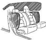
SS50521
FRONTSEAT-MOUNTEDSIDE-IMPACTSUPPLEMENTALAIRBAGAND ROOF-MOUNTEDCURTAINSIDE-IMPACTSUPPLEMENTALAIRBAGSYS-TEMS
Thesideairbagsarelocatedintheoutside of theseatback ofthefrontseats. The curtainairbagsarelocatedinthesideroof rails. However, alloftheinformation, cautionsandwarningsinthismanualstill applyandmustbefollowed. Thesideair bagsandcurtainairbagsaredesigned to inflatein higherseverity sidecollisions, although they may inflate if the forces in
another type of collisionaresimilar to thoseofahigherseveritysideimpact. They are designed to inflateonthesidewhere vehicleisimpacted. They may not inflate uncertaintiesidecollisionsontheside where the vehicleisimpacted. Vehicledamage(orlackofit)isnotalways anindicationofpropersupplementalside airbagandcurtainside-impactairbag operation.
Whensideairbagsandcurtainairbags inflate,afairlyloudnoisemaybebe heard, followedbyreleaseofsmoke. Thissmoke isnotharmfulanddoesnotindicateafire. Careshouldbetakennottoinhaleit,asit maycauseirritationandchoking.Those withahistoryofabreathingcondition shouldgetfreshairpromptly.
Sideairbags, alongwiththeuseofseat belts, helptocushiontheimimpactforceon thechestandpelvisofthefrontoccupants. Curtainairbagshelptocushiontheimimpact forcetotheheadofoccupantsinthefront andrearoutboardseatingpositions. They canhelpsavelivesandreduceserious injuries. However, aninflatingsdeairbags andcurtainairbagsmaycauseabrasions orotherinjuries. Sideairbagsandcurtain airbagsdonotproviderestraintintothe
lowerbody.
Theseatbeltsshouldbecorrectlyworn andthedriverandpassengerseated uprightasfaraspracticalawayfromthe sideairbag.Rearseatpassengershould beseatedasfarawayaspracticalfrom the doorfinshersandsideroforails. Theside airbagsandcurtainairbagsinflatequickly inordertohelprotecttheoccupants. Becauseofthis, theforceofthesideair bagsandcurtainairbagsinflatingcan increasetheriskofinjurylitheoccupantis toocloseto, orisagainst, theseairbag modulesduringinflation.Thesideairbags andcurtainairbagswilldeflatequickly afterthecollisionisover.
Thesideairbagsandcurtainairbags operateonlywhentheignitionswitchisin theONposition.
AfterpushingtheignitionswitchtotheON position,thesupplementalairbagwarninglightilluminates.Theairbagwarning lightwillturnoffafterabout7secondsif thesystemsareoperational.


WARNING
- Donotplaceanyobjectsnearthe seatbackofthefrontseats. Also, do notplaceanyobjects(anumbrella,bag, etc.) betweenthefrontdoorfinisherand thefrontseat. Suchobjectsmaybecome dangerousprojectilesandcauseinjuryif sideairbaginflates.
●Rightafterinflation,severalsideair bagsandcurtainairbagsystemcomponentswillbehot.Donottouchthem; youmayseverelyburnyourself.
- Nounauthorizedchangesshouldbe madetoanycomponentsorwiringof sideairbagandcurtainairbags. This is topreventdamagetooraccidental inflationofthesideairbagandcurtain airbagsystems.
- Donotmakeunauthorizedchangesto yourvehicle'selectricalsystem, suspensionsystemorsidepanel. This could affect properoperationofthesideair bagandcurtailnairbagsystems.
•Tamperingwiththeairbagsystemmay resultinseriouspersonallinjury. For example, donotchangethefrontseats byplacingmaterialneartheseatbackor
Safety — Seats, seat belts and supplemental restraint system
byinstallingadditionaltrimmaterial, suchasseatcovers,aroundthesideair bags.
-Workarounddonthesideairbagand curtainairbagsystemsshouldbedone byanINFINITretailer.Installationof electricalequipmentshouldalsobe donebyanINFINITretailer.TheSupple- mentalRestraintSystem(SRS)wiring harnesses"shouldnotbemodifiedor disconnected.Unauthorizedelectrical testequipmentandprobingdevices shouldnotbeusedontheside-impact airbagsystem.
*The SRSwiringharnessconnectors are yellow and orange foreasy identification.
Whensellingyourvehicle, werequestthat youinformthebuyeraboutthesideairbag andcurtainairbagsystemsandguidethe buyertotheappropriatesectionsinthis Owner'sManual.
SEATBELTSWITHPRETENSIONERS (frontseats)
WARNING
- Thepretensioners cannot bereused after activation. They must be replaced together with the retractor and buckle as a unit.
- If the vehicle becomes involved in collision but a pretensioner is not activated, besureto have the pretensioners system checked and, if necessary, replaced by an INFINIT retailer.
■Nounauthorizedchangesshouldbe madetoanycomponentsorwiringof thepretensioners. This is to prevent damage to accidental activation of the pretensionersystem. Tampering with the pretensionersystem may result in serious personal injury.
■Workaroundandonthepretensioners should bedonebyanINFINITretailer. Installationofelectricalequipment should also be done by an INFINIT retailer. Unauthorized electrical test equipment and probing devices should not be used on the pretensioner system.
- If you need to dispose of the pretensioner or scrap the vehicle, contact an INFINIT retailer. Correct pretensioner disposal procedures are set forth in the appropriate INFINIT Service Manual. Incorrect disposal procedures could cause personal injury.
Thepretensionersystem may activate with the supplemental air bag system in certain typesofcollisions.Workingwith the seat belt retractor, it helps tighten the seat belt whenthevehiclebecomesinvolvedin certaintyesofcollisions,helpingto restrainfrontseatoccupants.
Thepretensioneris encasedwiththe seat beltretractor. Theseseatbeltsareusedthe samewayasconventionalseatbelts.
Whenapretensionerseatbeltactivates, smokeisreleasedanda loudnoisemaybe heard. Thesmokeisnotharmful, andit doesnotindicateafire. Careshouldbe takennottoinhaleitasitmaycause irritation and choking. Those with a history of abreathingconditions should getfresh airpromptly.
Afterpretensioneractivation, loadlimiters allow the seat belt to release webbing (if necessary)toreduceforcesagainstthe
chest.
Thesupplementalairbagwarninglight isused to indicate malfunctions in the pretensionersystem. (See "Supplemental airbagwarninglight" (P. 1-55) formore details.) If the operation of these supplemental airbagwarning light indicates there is amalfunction, havethesystem checked by an INFINITretailer.
Whensellingyourvehicle, werequestthat youinformthebuyerabouttheseatbelt pretensionersandguidethebuyertothe appropriatesectionsinthisOwner'sManual.
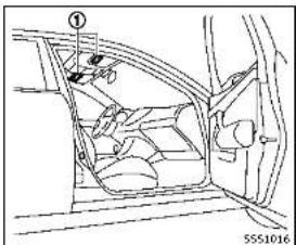
text_image
Technical diagram of a car interior with labeled components and part number 5551016SUPPLEMENTAL AIRBAG WARNING LABELS
Warninglabelsaboutthesupplemental front-impactairbagsystemsareplacedin thevehicleasshownintheillustration.
SRSairbag
Thewarninglabels ① arelocated on the surface of the sunvisors.
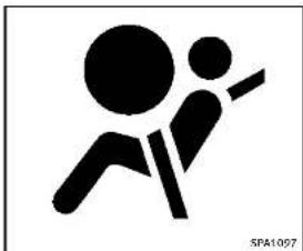
natural_image
Silhouette of two figures in motion, one climbing and one falling (no text or symbols)SUPPLEMENTALAIRBAGWARNING LIGHT
Thesupplementalairbagwarninglight, displaying intheinstrumentpanel, monitors the circuits for the airbag systems, pretensioners and all related wiring.
WhentheignitionswitchisintheON position,thesupplementalairbagwarning lightilluminatesforabout7secondsand thenturnsoft.ThismeanstheSRSairbag systemsareoperational.
Ifanyofthefollowingconditionsoccur,the airbagand/orpretensionersystemsneed

Safety - Seats, seat belts and supplemental restraint system
servicing:
- Thesupplementalairbagwarninglight remainsonafterapproximately7seconds.
- Thesupplementalairbagwarninglight flashes intermittently.
■Thesupplementalairbagwarninglight doesnotcomeonatall.
Undertheseconditions,theairbagor pretensionersystemsmaynotoperate properly.Theymustbecheckedand repaired.Takeyourvehicletothenearest INFINITretailer.

WARNING
If the supplemental airbag warning light is on, it could mean that the front airbag, side airbag, curtain airbag and or pretensioner systems will not operate in an accident. To help avoid injury to yourself for others, have your vehicle checked by a retailer as soon as possible.
REPAIRANDREPLACEMENTPROCEDURE
Thefrontairbags, sideairbags, curtainair bags and pretensioners are designed to activate one-time-only basis. As a reminder, unless it is damaged, the supplemental airbag warning light will remain illuminated after inflation has occurred. Repair and replacement of these systems should be done only by an INFINITire tailer. When maintenance work is required on the vehicle, the frontairbags, sideairbags, curtainairbags, pretensioners and related parts should be pointed out to the person conducting them maintenance. The ignition switch should always be in the LOCK position when working under the hoodor inside the vehicle.

WARNING
- Onceafrontairbag,sideairbag,or curtainairbaghasinflated,theairbag modulewillnotfunctionagainandmust be replaced. Additionally, the activated pretensioner must also be replaced. The air bag module and pretensioner should be replaced by an INFINITI retailer. The
airbagmoduleandpretensionersystem cannotberepaired.
- Thefrontairbag, sideairbag, curtainair bag and the pretensionersystem should be inspected by an INFINIT retailer if there is any damage to the frontor side portion of the vehicle.
- If you need to dispose of the supplemental air bag or pretensioner or scrap the vehicle, contact an INFINIT retailer. Correct supplemental air bag and seat belt pretensioners system disposals procedures are set forth in the appropriate INFINIT Service Manual. Incorrect disposals procedures could cause personal injury.
2Instrumentsandcontrols
Cockpit....2-3
Instrumentpanel....2-5
Metersandgauges....2-6
Speedometer and dB diameter 2-7 Tachometer 2-8
Enginecoolanttemperaturegauge....2-8
Fuelgauge 2.9
Compass(ifsoequipped)....2-9
Zonevariationchangeprocedure....2-11
Warning/indicatorlightsand
audiblereminders....2-12
Checkingbulbs....2-12
Warningights....2-12
Indicatorlights....2-17 Audible markers....3-10
Audiblereminders....2-19 Vehicleinformationdisplay....2-20
Indicatorsforoperation....2-22
Indicatorsformaintenance....2-25
Tripcomputer....2-28
Clockandoutsideairtemperature....2-30
Securitysystems....2-30
VehicleSecuritySystem.... 2-31
INFINITVehicleImmobilizerSystem.... 2-32
Windshieldwiperandwasherswitch....2-33
Rain-sensingautowipersystem(if
soequipped)....2-35
Rearwindowandoutsidemirror
defrosterswitch....2-36
Headlightandturnsignalswitch....2-36
Headlightswitch....2-36
Turnsignalswitch....2-42
Foglightswitch....2-42
Horn....2-42
VehicleDynamicControl(VDC)OFFswitch.....2-43
Poweroutlet....2-43
tray(ifsoequipped)....2-44
Rear....2-4
Storage....2-44
Cupholders....2-44
Softbottleholder....2-45
Sunglassesholder....2-46
Glovebox....2-46
Consolebox....2-47
Cardholder....2-47
Storage box 2-
Coat hooks 2-
Trunk hooks 2-
Windows....2-49
Powerwindows....2-49
Moonroof(ifsoequipped)....2-51
Automaticmoonroof....2-51
Interiorlights....2-53
Maplights....2-53
Consolelight(ifsoequipped)....2-53
Personallights....2-54
Interiorlightcontrolswitch....2-54
Vanitymirrorlights....2-55
Trunklight....2-55
Courtesy 2-56
HomeLink® UniversalTransceiver(if
soequipped)....2-56
ProgrammingHomeLink ^③ 2-57
ProgrammingHomeLink ^10 forCanadian
customersandgateopeners....2-58
OperatingtheHomeLink ^4
UniversalTransceiver......2-59
Programmingtroubleshooting....2-59
Clearingtheprogrammedinformation......2-59
Reprogrammingasing
HomeLink® button....2-59
Ifyourvehicleisstolen....2-60
COCKPIT

text_image
Technical diagram of a car interior with numbered components for identification- Sideventilator(P.4-2)
- Headlight, foglight and turnsignal switch(P.2-36)
- Steeringwheel —Horn(P.2·42)
- Drivers supplemental airbag (P.1-42)
- Heated steering wheel* (if so equipped)
-
Steering system (P.5-104)
-
Windshieldwiperandwasherswitch (P.2-33)
5.Hazardwarningflasherswitch(P.6-2)
6.Shiftlever(P.5-15)
7.INFINITcontroller*
8.VehicleDynamicControl(VDC)OFF switch(P,2-43,P,5-108)
-
Trunklidreleaseswitch(P.3-19)
-
Instrument brightness control switch (P.2-41)
11.TRIP/RESETswitchfortwintripodometer(P.2-7)
-
Electric tilting/telescopic steering wheelswitch(P.3-24)
-
Manualtilting/telescopicsteering wheellever(P.3-24)
-
Steering-wheel-mounted controls(left side)
—Audiocontrolsteeringswitch* —Hands-FreePhoneSystemswitch* —Voicerecognitionsystemswitch*
- Steering-wheel-mounted controls (rightside)
—Tripcomputerswitch(P.2-28)
—Cruisecontrolswitches(ifso
equipped)(P.5-56)
—IntelligentCruiseControl(ICC)
switches(ifsoequipped)(P.5-58)
Instrumentsandcontrols2·3
—Dynamicdriverassistanceswitch (Ifsoequipped)(P.5-30,P.5-37, P.5-79) 16.INFINITIDriveModeSelector(P.5-21) *:RefertoTheInfinitiInTouchOwner's Manual.
2-4Instrumentsandcontrols

INSTRUMENTPANEL

text_image
1 9 S 4 5 6 7 8 9 10 11 12 13 14 15 16 JMC0427X- Paddleshifter(ifsoequipped)(P.5-17)
2.Metersandgauges(P.2-6)
-Clock(P.2-30)
3.Push-buttonignitionswitch(P.5-10)
- Centerventilator(P.4-2)
5.Automaticclimatecontrolsystem*
6.Uppertouchscreendisplay(upper display)*andNavigationsystem*(if soe quipped)
-
Lower touch screen display (lower diaplay)*
-
Rear window and outside mirror
defrosterswitch(P.2-36)
9.Frontpassengersupplementalairbag (P.1-42)
10.Hoodreleasehandle(P.3-18)
11.Fuseboxcover(P.8-22)
- Parkingbrake(P.5-20)
13.Seatheaterswitch*(ifsoequipped)
14.Audiosystem*
- Trunkreleasepowercancelswitch (P.3-20)
16.Glovebox(P.2-46)
*:RefertotheInfinitiInTouchOwner's Manual.
METERSANDGAUGES
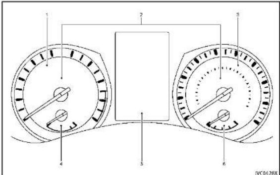
text_image
1 2 3 4 5 6 JVC0428X1.Tachometer*(P.2-8)
- Warning/Indicatorlights(P.2-12)
3.Speedometer*(P.2-7)
- Enginecoolanttemperaturegauge* (P.2-8)
5.Vehicleinformationdisplay(P.2-20)/
2-6 Instrumentsandcontrols
Odometer/twintripodometer(P.2-7)
6.Fuelgauge*(P.2-9)
*: The needle indicators may move slightly after the ignition switch is placed in the OFF position. This is not a malfunction.

CAUTION
- Forcleaning, useasoftcloth, dampened with water. Neverusearoughcloth, alcohol, benzine, thinneroranykind of solventorpapertowelwithachemical cleaningagent. They will scratch or causediscolorationtothelens. - Donotsprayanyliquidsuchaswateron themeterlens. Sprayingliquidmay causethesystemtomalfunction.
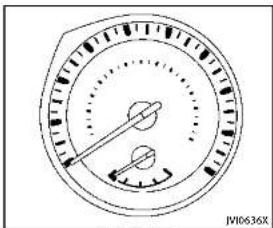
text_image
JV10636XSpeedometer

text_image
TRIP RESET ③ 0.0 micro 0.0 @ ① ② JV10637XOdometer/twintripodometer
TRIPA→TRIPB→TRIPA
Resettingthetripodometer:
PushingtheTRIPRESETswitch ① formore than1secondresetsthetripodometerto zero.
SPEEDOMETERANDODOMETER
Speedometer
Thespeedometer indicates vehiclespeed in miles per hour (MPH) and kilometers per hour (km/h).
Odometer/twintripodometer
Theodometer ① andtwintripodometer ② aredisplayedinthevehicleinformation displaywhentheignitionswitchisinthe ONposition.
Theodometerrecordsthetotaldistance thevehiclehasbeendriven. Thetwintripodometerrecordsthedistanceofindividualtrips.
Changing the display:
Pushing the TRIP RESET switch ③ under the combination meter panel changes the displaya s follows:
Instrumentsandcontrols2·7
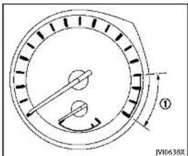
text_image
JW10638XTACHOMETER
Thetachometer indicates enginespeedin revolutions per minute (RPM). Donotrev the engine into a theredzone ①.
Thescalelengthandtheredzonevarywith theenginemodel.

CAUTION
Whenenginespeedapproachesthered zone,shifttoahighergearorreduceengine speed.Operatingtheengineintheredzone maycauseseriousenginedamage.
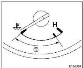
text_image
F H ① JV10638XThegaugeindicates the engine coolant temperature.
Theenglnecoolanttemperatureiswithin thenormalrangewhenthegaugeneedle pointswithinthezone ① showninthe illustration.
The enginecoolanttemperaturevarieswith theoutsideairtemperatureanddriving conditions.


CAUTION
Ifthegaugeindicatesheenginecoolant temperatureisnearthehot(H)endothe normalrange, reducevehiclespeedto decrease the temperature.Ifthegaugeis overthenormalrange,stopthevehicleas soon assafely possible and the engine idle.Iftheg engine is overheated, continued operation of the vehicle may seriously damage the engine.See "If your vehicle overheats"(P.6-12) for immediate action required.
2-8 Instrumentsandcontrols
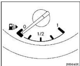
text_image
0 1/2 1 JW10640XFUELGAUGE
Thegaugeindicates the approximate fuel level in the tank.
Thegaugemaymoveslightlyduring braking,turning,acceleration,orgoingup ordownhills.
Thegaugeneedlereturnsto "0"(Empty) aftertheignitionswitchispushedtothe OFFposition.
Refillthefueltankbeforethegauge registers"0"(Empty).
Thelowfuelwarninglight illuminates onthemeterwhenthefuellevelisgetting low. Refuelassoonasitisconvenient,
preferablybeforethegaugereaches "0". Therewillbeasmallreserveoffuelinthe tankwhenthefuelgaugeneedlereaches "0".
The ▶ indicate that the fuel-filled door is located on other right sides of the vehicle.
CAUTION
- Ifthevehiclerunsoutoffuel, the malfunctionindicatorlight(MIL) may comeon. Refuelassoonaspossible. Afterafewdrivingtrips, the shouldturnoff. Ifthelightremainson afterafewdrivingtrips, havethevehicle inspectedbyanINFINITretailer.
- For additional information, see "MalfunctionIndicatorLight(MIL)"(P.2-18).

COMPASS(ifsoequipped)

text_image
A B S/C31R1Whentheignitionswitchispushedtothe ONposition, thecompassdisplay ⑧ will indicate the direction of the vehicle's heading.
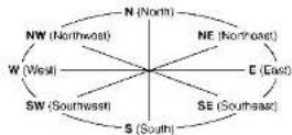
Ifthedisplayreads"C", calibratethe compassbydrivingthevehiclein3 completecirclesatlessthan5MPH(8
km/h).Youcanalsocalibratethecompass bydrivingyourvehicleonyoureveryday route. Thecompasswillbecalibratedonce ithastracked3completecircles.
Totumonandoffthecompassmanually, pushthe - switch Ⓐ whiletheignition switchisintheONposition.
text_image
SIC0611BZonemap
2-10 Instrumentsandcontrols

ZONEVARIATIONCHANGEPROCEDURE
The difference between magnetic north and geographical north is known as variance. In some areas, this difference can sometimes begreten out a cause false compass readings. Follow these instructions to set the variance for your particular location if this happens:
-
Pushthe → switchformorethan3 seconds. The current zonumber will appear in the display.
-
Find your current location and variance number on the zonemap.
3.Pushthe - switchrepeatedlyuntil thenewzonumberappearsinthe display,thenreleasetheswitch.After youreleasetheswitch,thedisplaywill showacompassdirectionwithinafew seconds.
- Ifthecompassdeviatesfromthe correctindicationsoonafterrepeatedadjustment,havethecompasscheckedatanINFINITretailer.
- Thecompassmaynotindicate the correctcompasspointintunnelsor while drivingupordownasteephill. (Thecompassreturnstothecorrect
compasspointwhenthevehicle movestoanareawherethegeomagnetismisstabilized.)
CAUTION
- Donotinstallaskirack, antenna, etc., which are attached to the vehicle by means of magnet. They affect the operation of the compass.
- Whencleaningthemirror, useapaper towelorsimilarmaterialdampenedwith glasscleaner. Donotsprayglasscleaner directlyonthemirrorasitmaycausethe liquidcleanertoenterthemirrorhousing.

Instrumentsandcontrols2·11
WARNING/INDICATOR LIGHTSAND
AUDIBLEREMINDERS
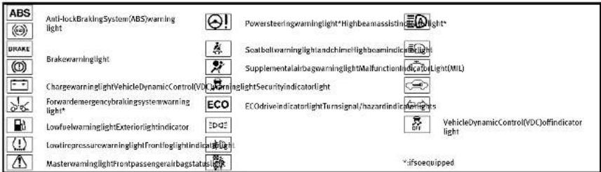
text_image
ABS Anti-lockBrakingSystem(ABS)warning light Powersteeringwarninglight*Highbeamassisting Light* DRAKE Brakewarninglight ScatbellwarninglightandchimeHightcamindic light SupplementalairbagwarninglightMalfunctionlndicatbyLight(MIL) ChargewarninglightVehicleDynamicControl(VDC)WarninglightSecurityIndicatorlight Forwardemergencybrakingsystemwarning light* ECO ECOdriveIndicatortlightTurnsignal/hazardIndicatioring light* LowfirewarninglightExteriorlightindicator VehicleDynamicControl(VDC)offindicator light LowfiregressurewarninglightFrontlightlightIndicatorlight MasterwarninglightFrontpassengerairbagstatuslight -ifsoequippedCHECKINGBULBS
Withalldoorsclosed, apply the parking brake and push the ignition switch to the ON position without starting the engine. The following lights will come on (if so equipped):
,or,,,
The following lightscomeonbriefly and thengooff(if soequipped):
A , ABS or (B), C , D , (L), ECO If any light does not come on, it may indicate a burned-out bulb or an open circuitintheelectricalsystem.Havethe
2-12 Instrumentsandcontrols
systemcheckedbyanINFINITretailer.
Some indicators and warnings are also displayed in the vehicle information display between the speedometer and tachometer.(See "Vehicleinformationdisplay" (P.2-20).)

WARNINGLIGHTS
ABS or Anti-lock Braking System (ABS) warninglight
When the ignition switch is in the ON position, the Anti-lock Braking System (ABS) warning light illuminates and then turns off. This indicates the ABS is operational.
If the ABS warning light illuminates while theengineisrunning,orwhiledriving,it may indicate the ABS is not functioning properly. Have thesystemchecked byan
INFINITretailer.
IfanABSmalfunctionoccurs, theanti-lock functionisturnedoff. Thebrakesystem thenoperatesnormally, but without anti-lock assistance. (See "Brakesystem" (P.5-106).)
BRAKE or B(①) kewarninglight
Thislightfunctionsforboththeparking brakeandthefootbrakesystems.
Parkingbrakeindicator:
WhentheignitionswitchisintheON position,thelightcomesonwhenthe parkingbrakeisapplied.
Lowbrakefluidwarninglight:
WhentheignitionswitchisintheON position,thelightwamsofalowbrake fluidlevel.Ifthelightcomesonwhilethe engineisrunningwiththeparkingbrake notapplied,stopthevehicleandperform thefollowing:
-
Check the brake fluid level. If brake fluid is necessary, add fluid and have the system checked by your INFINITE retailer. (See "Brakefluid" (P.8-13).)
-
If the brake fluid level is correct, have the warnings system checked by an INFINIT retailer.
Anti-lockBrakingSystem(ABS)warning indicator:
When the parking brake is released and the brake fluid level insufficient, if both the braking warning light and the Anti-lock Braking System (ABS) warning light illuminate, it may indicate the ABS is not functioning properly. Have the brakesystem checked, and if necessary repaired, by an INFINIT retailer promptly. (See "Anti-lock Braking System (ABS) warning light" (P.2-12).)
WARNING
- Yourbrakesystemmaynotbeworking properlyifthewarninglightison. Drivingcouldbedangerous.Ifyoujudge ittobesafe,drivecarefullytothe nearestservicestationforrepairs. Otherwise,haveyourvehicletowed becausedrivingitcouldbedangerous.
- Pressingthebrakepedalwiththe enginestoppedand/orlowbrakefluid level may increase your stopping distance and braking will require greater pedal effort as well as pedal travel.
• If the brake fluid level is below the
minimumorMINmarkonthebrakefluid reservoir, donotdriveuntilthebrake systemhasbeencheckedatanINFINITI retailer.

Chargewarninglight
lfthelightcomesonwhiletheengineis running, itmayindicatethecharging systemisnotfunctioningproperly. Turn theengineoffandcheckthealternator belt. Ifthebeltisloose, broken, missingor ifthelightremainson, seeanINFINITI retailerimmediately.

CAUTION
Donotcontinuedrivingifthealternatorbelt isloose,brokenormissing.

Forwardemergencybraking mwarninglight(ifso ped)
Thislightilluminateswhentheforward emergencybrakingsystemissettoOFFon thelowerdisplay.
Ifthelightilluminateswhentheforward emergencybrakingsystemisON,itmay
Instrumentsandcontrols
indicate that the system is unavailable. See "Forward emergency braking system" (P.5-89) formoredetails.

Lowfuelwarninglight
Thislightilluminateswhenthefuelinthe tankisgettinglow.Refuelassoonasitis convenient,preferablybeforethefuel gaugereachesthe0(empty)position.
Therewillbeasmallreserveoffuel remaininginthetankwhenthefuelgauge reaches the0position.
Lowtirepressurewarning light
Your vehicle is equipped with a Tire Pressure Monitoring System (TPMS) that monitor the tire pressure of all tires except the spare tire (if so equipped).
Thelowtirepressurewarninglightwarns oflowtirepressureandflattireor indicatesthattheTPMSisnotfunctioning properly.
AftertheignitionswitchisplacedintheON position, thislightilluminatesforabout1 secondandturnsoff.
Lowtirepressurewarning:
Ifthevehicleisbeingdrivenwithlowtire pressure,thewarninglightwillilluminate. The"TirePressureLow-AddAir"warning alsoappearsinthevehicleinformation display.
Whenthelowtirepressurewarninglight illuminates,youshouldstopandadjust thetirepressureretotherecommended COLDtirepressureshownontheTireand LoadingInformationlabel.Thelowtire pressurewarninglightdoesnotautomaticallyturnoffwhenthetirepressureis
adjusted, After the tire is inflated to the recommended pressure, they vehicle must be driven at speeds above 16 MPH (25 km/h) to activate the TPMS and turn off the low tire pressure warning light. Use tire pressure gaugeto check the tire pressure. The "Tire Pressure Low-Add Air" warning is active as long asthe low tire pressure warning light remains illuminated.
For additional information, see "Vehicle information display" (P.2-20), "Tire Pressure Monitoring System (TPMS)" (P.5-4) and "Tire Pressure Monitoring System (TPMS)" (P.6-3).
Run-flattirewarning:
Therun-flattirewarningwamsofaflattire. Ifthevehicleisbeingdrivenwithoneor moreflattires,thelowtirepressure warninglightwillilluminatecontinuously andachimewillsoundfor10seconds.A
"FlatTire-Visitdealer" warning also appears in the vehicle information display.
Thechimewllionlysoundattnerlist indicationofaflattireandthewarning lightwillilluminatecontinuously. Whenthe flattirewarningisactivated, havethe systemresetandthetirechecked, and replacedifnecessary, byanINFINITI retailer.Evenifthetireisinflatedtothe specifiedCOLDtirepressure, thewaming lightwillcontinuetoilluminateuntilthe systemisreset, byanINFINITItretailer.
Yourvehiclecanbedrivenforalimited timeonaflattire.See"Run-flattires"(P.6-4).
TPMSmalfunction:
If the TPMS is not functioning properly, the low-tire pressure warning light will flash for approximately 1 minute when the ignition switch is placed in the ON position. The light will remain on after the 1 minute. Havethesystem checked by an INFINITI
2-14Instrumentsandcontrols
retailer. The "TirePressureLow-AddAir" warningdoesnotappearifthelowtire pressurewarninglightilluminatestoin-dicateaTPMSmalfunction.
Foradditionalinformation,see"TirePressureMonitoringSystem(TPMS)("(P.5-4).

WARNING
•Radiowaves could adversely affect electric medicalequipment. Those who use apacemakers should contact the electric medicalequipment manufacturer for the possible influences before use.
- If the light does not illuminate with the ignitionswitch pushed ON, have the vehicle checked by an INFINIT retailer as soon as possible.
- Ifthelightilluminateswhiledriving, avoidsuddensteeringmaneuversor abruptbraking, reducevehiclespeed, pullofftheroadtoasafelocationand stopthevehicleassoonaspossible. Drivingwithunder-inflatedtiresmay permanentlydamagethetiresandincreasethelikelihoodoffirefailure. Seriousvehicledamagecouldoccur andmayleadtoanaccidentandcould
resultinseriouspersonalinjury.Check the tirepressureforalfourtries.Adjust the tirepressuretotherecommended COLDtrepressureshowontheTire and LoadingInformationlabeltoturn the lowtirepressurewarninglightOFF.If the lightstillilluminateswhiledriving afteradjustingthetirepressure,atire maybeflat.Ifyouhaveaflattire, replaceitwithasparetire(ifso equipped).
Although you can continue driving with a punctured run-flattire, remember that vehicle handling stability is reduced, which could lead to an accident and personal injury. Also, driving along distance at high speed may damage the tires.
- Donotdriveatspeedsabove50MPH (80km/h)anddonotdrivemorethan approximately 93 miles (150 km) with a puncturedrun-flattire. The actual distance the vehicle can be driven on a flat tire dependence outside temperature, vehicle load, road conditions and other factors.
- If you detect any unusual sounds or vibrations while driving with a punctured run-flat tire, pull off the road to a safe
locationandstopthevehicleassoonas possible. Thetiremaybeseriously damagedandneedtobereplaced.
- Whenasparetireismountedorawheel isreplaced, theTPMSwillnotfunction and thelowtirepressurewarninglight willflashforapproximately1minute. Thelightwillremainonafterthe1 minute. ContactyourINFINITretaileras soonaspossiblefortirereplacement and/orsystemresetting.
- Replacing tires with those not originally specified by INFINIT could affect the proper operation of the TPMS.

CAUTION
•TheTPMSisnotasubstituteforthe regulartirepressurecheck.Besureto checkthetirepressureregularly.
- If the vehicle is being driven at speed of less than 16 MPH (25 km/h), the TPMS may not operate correctly.
- Besuretoinstallthespecifiedsizeof tirestothefourwheelscorrectly.

Masterwarninglight
WhentheignitionswitchisintheON position,themasterwarninglightilluminatesifanyofthefollowingwarnings appearinthevehicleinformationdisplay:
■Nokeywarning
●PUSHwarning
■KeyIDIncorrectwarning
●Lowwasherfluidwarning
■Door/trunkopenwarning
- Loosefuelcapwarning
■TirePressureLow-AddAirwaming
- FlatTire-Visitdealerwarning
- All-WheelDrive(AWD)warning(ifso equipped)
■Headlightwarning
●AdaptiveFrontlightingSystem(AFS) warning(ifsoequipped)
■IntelligentKeysystemwarning
●Chassiscontrolwarning
See "Vehicleinformationdisplay"(P.2-20).
If the driver assists system warnings appear in the vehicle information display, the master warning light also illuminates. See "Lane Departure Warning (LDW) system / Lane Departure Prevention (LDP) system" (P.5-30), "Blind Spot Warning/Blind Spot
Intervention™/Back-upCollisionInterventionsystems"(P.5-37),"DistanceControl Assist(DCA)system"(P.5-79),"Forward emergencybrakingsystem"(P.5-89)and "Predictiveforwardcollisionwarningsystem"(P.5-94).
Powersteeringwarninglight (ifsoequipped)
WhentheignitionswitchisintheON position,thepowersteeringwarninglight illuminates.Afterstartingtheengine,the powersteeringwarninglighttumsoff.This indicatesthatthedirectadaptivesteering systemisoperational.
If the power steering warning light illuminates while the engine is running, it may indicate the direct adaptive steering system is not functioning properly and may need servicing. Havethedirect adaptive steering system checked by an INFINIT retailer. (See "Direct adaptive steering type" (P. 5-104).)

Seatbeltwarninglightand
The light and chime remind you to fasten seat belts. The light illuminates whenever the ignition switch is pushed to the ON
position, and will remain illuminated until the driver's seatbelt is fastened. At the same time, the chimewill sound for about 6 seconds unless the driver's seatbelt is securely fastened.
Theseatbeltwarninglightforthefront passengerwillilluminateiftheseatbeltis notfastenedwhenthefrontpassenger's seatisoccupied.Forapproximately/ secondsaftertheignitionswitchisinthe ONposition,thesystemdoesnotactivate thewarninglightforthefrontpassenger. See"Seatbelts"(P.1-12)forprecautions onseatbeltusage.

Supplementalairbagwarning
AfterpushingtheignitionswitchtotheON position,thesupplementalairbagwarning lightwillilluminate.Thesupplementalair bagwarninglightwillturnoffafterabout7 secondsifthesupplementalfrontairbag andsupplementalsideairbag,curtain side-impactairbagsystemsand/orpre-tensionerseatbeltareoperational.
Ifanyofthefollowingconditionsoccur,the supplementalfrontairbag,supplemental sideairbag,supplementalcurtainside-impactairbagandpretensionerseatbelt
2-16 Instrumentsandcontrols
needsservicingandyourvehiclemustbe takentoyournearestINFINITretailer.
- Thesupplementalairbagwarninglight remainsonafterapproximately7seconds.
●Thesupplementalairbagwarninglight flashesintermittently.
■Thesupplementalairbagwarninglight doesnotcomeonatall.
Unless checked and repaired, the Supplemental Restraint Systems and orthepretensioner seat belt may not function properly.
Foradditionalinformation,see"Supplementalrestraintsystem"(P.1-42).

WARNING
If the supplemental airbag warning light is on, it could mean that the supplemental frontairbag, supplementalsideairbag, curtainside-impact airbagsystems and pretensioner seat belt will not operate in an accident. To help avoid injury to yourself for others, have your vehicle checked by a retailer as soon as possible.

VehicleDynamicControl(VDC) inglight
ThelightwillblinkwhentheVehicle DynamicControl(VDC)systemorthe tractioncontrolsystemisoperating,thus alertingthedriverthatthevehicleis nearingitstractionlimits.Theroadsurface maybeslippery.
WhentheVDCwarninglightilluminates whentheVDCsystemisturnedon,this lightalertsthedirivetothefactthatthe VDCsystem'sfail-safemodeisoperating, foreampletheVDC,activetracecontrol function,BrakeForceDistributionorhill startassistsystemmaynotbefunctioning properly.Havethesystemcheckedbyan INFINITretailer,Ifamalfunctionoccursin thesystem,theVDCsystemfunctionwill becanceledbutthevehicleisstilldrive- able.ForadditionalInformation,see"VehicleDynamicControl(VDC)system"(P.5- 108).

DEALER
INDICATORLIGHTS
ECO ECOdriveindicatorlight
Whentheignitionswitchispushedtothe ONposition,thelightwillcomeonand thenturnoff.
WhentheINFINITIDriveModeSelectoris turnedtotheECOmode,theECOdrive indicatorlightwillilluminate,blinkor remainoffdependingontheaccelerator pedaloperationtohelpassistthedriverte driveeconomically.Formoredetails,see "ECOmode"(P.5-22).

Exteriorlightindicator
Thisindicatorilluminateswhenthehead- lightswitchisturnedtotheAUTO, or
2D positionandthefrontparkinglights, instrumentpanellights, rearcombination lights, licenseplatelightsorheadlightsare on. The indicatorturnsoffwhenthese lightsareturnedoff.
Frontfoglightindicatorlight Thefrontfoglightindicatorlightilluminateswhenthefrontfoglightsareon.(See "Foglightswitch"(P.2-42).)

Frontpassengerairbagstatus
Thefrontpassengerairbagstatuslight ( ) located on the instrument panel will belit and the passenger front air bag will be OFF depending on how the front passenger seat is being used.
Forfrontpassengerairbagstatuslight operation, see "INFINITIAdvancedAirBag System(frontseats)" (P.1-47).

Highbeamassistindicator (ifsoequipped)
The indicator light illuminates when the headlights come on while the headlight switch in the AUTO position with the highbeam selected. This indicates that the highbeam assists system is operational. (See "Highbeam assist" (P.2-38).)
Highbeamindicatorlight Thislightcomesonwhentheheadlight highbeamisonandgoesoutwhenthelow beamisselected.

MalfunctionIndicatorLight
Ifthemalfunctionindicatorlightcomeson steadyorblinkswhiletheengineis
2-18 Instrumentsandcontrols
running, it may indicate a potential emission control malfunction.
Themalfunctionindicatorlightmayalso comeonsteadyifthefuel-fillercapisloos ormissing,orifthevehiclerunsoutoffuel Checktomakesurethefuel-fillercapis installedandclosedtightly,andthatthe vehiclehasatleast3USgallons(11.4 liters)offuelinthefueltank.
Afterafewdrivingtrips, the shouldturnoffifnootherpotential emissioncontrolsystemmalfunctionexists.
If this indicator light remains on for 20 seconds and then blinks for 10 seconds when the engine is not running, it indicates that the vehicle is not ready for an emission control system inspection / maintenance (See "Readiness for inspection / Maintenance (I/M) test (US only)" (P.9-22).)
Operation:
Themalfunctionindicatorlightwillcome oninoneoftwoways:
- Malfunction indicator light on steady — An emission control system malfunction has been detected. Check the fuel-filler cap if the Loose Fuel Cap waming
appearsinthevehicleinformationdisplay.Ifthefuel-fillercapislooseor missing,tightenorinstallthecapand continuetodrivethevehicle.The lightshouldturnoffafterafewdrivingtrips.Ifthe .lightdoesnotturnoff afterafewdrivingtrips,havethe vehicleinspectedbyanINFINITretailer.Youdonotneedtohaveyour vehicleletowedtotheretailer.
- Malfunctionindicatorlightblinking—Anenginemisfirehasbeendetected whichmaydamagetheemissioncontrolsystem.
Toreduceoravoidemissioncontrol systemdamage: 1) Donotdriveatspeedsabove45 MPH(72km/h).
2) Avoid hard acceleration or deceleration.
3) Avoid steepuphillgrades. 4) If possible, reduce the amount of cargobeing hauledortowed.
Themallfunctionindicatorlightmay stopblinkingandremainon. Havethevehicleinspectedbyan INFINITretailer.Youdonotneedto haveyourvehicletowedtotheretaile

CAUTION
Continued vehicle operation without having the emission control system checked and repaired as necessary could lead to poor driveability, reduced fuel economy, and possible damage to the emission control system.

Securityindicatorlight
Thelightblinkswhentheignitionswitchis intheACC,OFForLOCKposition.This functionindicateshesecuritysystem equippedonthevehicleisoperational. If thesecuritysystemismalfunctioning, thislightwillremainonwhiletheignition switchisintheONposition.Foradditional information,see"Securitysystems"(P.2-30).

Turnsignal/hazardindicator
lights
Thelightflasheswhentetheturnsignal switchleverorhazardswitchisturnedon.

VehicleDynamicControl(VDC) Indicatorlight
ThelightcomesonwhentheVehicle DynamicControl(VDC)offswitchispushed toOFF. This indicates that the VDC system and traction control system are not operating.
AUDIBLEREMINDERS
Keyreminderchime
Achimewillsoundifthedriversidedooris openedwhiletheignitionswitchispushed totheACCposition.Makesuretheignition switchispushedtotheOFFposition,and takethelIntelligentKeywithyouwhen leavingthevehicle.
Lightreminderchime
Achimewillsoundwhentedriverside doorisopenedwiththelightswitchinthe nor orpositionandtheignitionswitch intheACC,OFFForLOCKposition. Turnthelightswitchoffwhenyouleavethe vehicle.
Parking brake reminder chime
The parking brake reminder chime will sound if the vehicle is driven at more than 4 MPH (7 km/h) with the parking brake
applied. Stopthevehicleandreleasethe parkingbrake.
Brakepadwearwarning Thediscbrakepadshaveaudiblewear warnings. Whenabrakepadrequires replacement, itwillmakeahighpitched scrapingsoundwhenthevehicleisin motion. Thisscrapingsoundwillfirstoccur onlywhenthebrakepedalisdepressed. Aftermorewearofthebrakepad, the soundwillalwaysbeheardevenifthe brakepedalisnotdepeared. Havethe brakescheckedassoonaspossibleifthe warningsoundisheard.
VEHICLEINFORMATIONDISPLAY
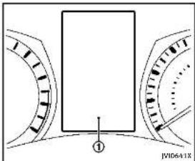
text_image
① JWID6A1XThevehicleinformationdisplay ① is locatedbetweenthetachometerandthe speedometer,anditdisplaysthewarnings andinformation.Thefollowingitemsare alsodisplayedifthevehicleisequipped withthem:
●Automatictransmission(AT)
- " Drivingthevehicle"(P.5-15)
All-WheelDrive(AWD)
- "IntelligentAll-WheelDrive(AWD)" (P.5-101)
■Cruisecontrol
- "Cruisecontrol"(P.5-56)
•IntelligentCruiseControl(ICC)
- "IntelligentCruiseControl(ICC)sys-
tem"(P.5-58)
●ActiveLaneControl
- "ActiveLaneControl"(P.5-24)
●LanedepartureWarning(LDW)/Lane
DeparturePrevention(LDP)system
- " LaneDepartureWarning(LDW)sys-
tem/LaneDeparturePrevention
(LDP)system"(P.5-30)
●BlindSpotWarning(BSW)/BlindSpot
Intervention™ (BSI)/Back-upCollision
Intervention(BCI)systems
"BlindSpotWarning/BlindSpot
Intervention™/Back-upCollisionIn-
terventionsystems"(P.5-37)
•DistanceControlAssist(DCA)system
— “ DistanceControlAssist(DCA)sys-
tem"(P.5-79)
●Forwardemergencybrakingsystem
— “ Forwardemergencybrakingsys-
tem"(P.5-89)
●Predictiveforwardcollisionwarning
system
— "Predictive forward collision warn-
ing system" (P.5-94)
.
.
2-20Instrumentsandcontrols
- "Activetracecontrol"(P.5-110)
●IntelligentKeysystem
- "IntelligentKeysystem"(P.3-6)
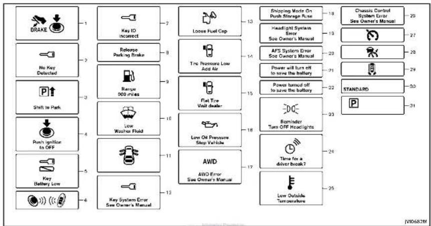
flowchart
graph TD
    A["DRAKE"] --> B["1"]
    C["No Key Detected"] --> D["2"]
    E["Shift to Park"] --> F["3"]
    G["Push ignition to OFF"] --> H["4"]
    I["Key Battery Low"] --> J["5"]
    K["Key System Error See Owner's Manual"] --> L["6"]
    B --> M["7"]
    D --> N["8"]
    F --> O["9"]
    H --> P["10"]
    J --> Q["11"]
    L --> R["12"]
    M --> S["Loose Fuel Cap"]
    N --> T["Free Range 000 miles"]
    O --> U["Flat Tire Visit dealer"]
    P --> V["Low Washer Fluid"]
    Q --> W["Low On Pressure Stop Vehicle"]
    R --> X["AWD AWD Error See Owner's Manual"]
    S --> Y["Shipping Mode On Push Storage Fuse"]
    T --> Z["Headlight System Error See Owner's Manual"]
    U --> AA["AFS System Error See Owner's Manual"]
    V --> AB["Power will turn off to save the battery"]
    W --> AC["Power turned off to save the battery"]
    X --> AD["DOE Reminder Turn OFF Headlights"]
    Y --> AE["Time for a driver break?"]
    Z --> AF["Standard"]
    AA --> AG["Low Outside Temperature"]
    AB --> AH["Chassis Control System Error See Owner's Manual"]
    AC --> AI["V10682M"]

Instrumentsandcontrols2·21
INDICATORSFOROPERATION
- Enginestartoperationindicator Thisindicatorappearswhentheshiftlever isintheP(Park)position.
This indicator means that the engine will start by pushing the ignition switch with the brake pedal depressed. You can start the engine directly in any position of the ignition switch.
2. NOKEYwarning
Thewarningappearswhenthedooris closedwiththelIntelligentKeyleftoutside thevehicleandtheignitionswitchinthe ACCorONposition.Makesurethatthe IntelligentKeyisinsidethevehicle. See“IntelligentKeysystem”(P.3-6)for moredetails.
3.SHIFT"P"warning
This warning appears when the ignition switch is pushed to stop the engine with the shift lever in any position except the P (Park) position.
If this warning appears, movetheshift levertotheP(Park)positionorpushthe ignitionswitchtotheONposition. Aninsidewarningchimewillalsosound.
2-22 Instrumentsandcontrols
(See "Troubleshootingguide" (P.3-13).)
4. "PUSH" warning
This warning appears when the shift lever is moved to the Park position with the ignition switch in the ACC position after the SHIFT "P" warning appears.
TopushtheignitionswitchtotheOFF position,performthefollowingprocedure:
- SHIFT "P" warning → (Move the shift lever to "P") → PUSH warning → (Push theignitionswitch → ignitionswitch positionisturnedtoON) → PUSH warning → (Pushtheignitionswitch → ignitionswitchpositionisturnedto OFF)
5. Intelligent Key battery discharge indicator
This indicator appears when the Intelligent Key battery is running out of power.
If this indicator appears, replace the battery with anewone. (See "Intelligent Keybattery replacement" (P.8-24).)
6. Engine start operation for IntelligentKey system indicator
This indicator appears when the Intelligent Key battery is running out of power and
whentheIntelligentKeySystemand vehiclearenotcommunicatingnormally. If this indicator appears, touch the ignition switch with the Intelligent Key while depressing the brake pedal. (See "IntelligentKey battery discharge" (P. 5-13).)
7.KeyIDIncorrectwarning
The warning appears when the ignition switch is pushed from the LOCK position and the Intelligent Key cannot be recognized by the system. You cannot start the engine with an unregistered key. Use the registered Intelligent Key.
See"IntelligentKeysystem"(P.3-6).
8. Parkingbrakereleasewarning This warning appears when the vehicle speed is above 4 MPH (7 km/h) and the parkingbrake is applied.
9.Lowfuelwarning
This warning appears when the fuel level in the tank is getting low. Refuel as soon as it is convenient, preferably before the fuel gaugereachesthe empty (0) position.
Thereisasmallreserveoffuelremaining inthetankwhenthefuelgaugereaches theempty(0)position.
-
Lowwasherfluid warning This warning appears when the washer tank fluid is at low level. Add washer fluid as necessary. (See "Windowwasherfluid" (P.8-14).)
-
Door/trunkopenwarning This warning appears if any of the doors and orthetrunklid are open or not closed securely. The vehicle icon indicates which door orthetrunklid is open on the display.
-
IntelligentKeysystemwarning ThiswarningappearsifthereisamallfunctionintheIntelligentKeysystem. If thiswarningappearswhiletheengineis stopped,theenginecannotbestarted.If thiswarningappearswhiletheengineis running.thevehiclecanbedriven.However,contactanINFINITretailerforrepair assoonaspossible.
-
LooseFuelCapwarning This warning appears when the fuel-filler capis not tightened correctly after the vehicle has been refueled. (See "Fuel-filler
cap"(P.3-22).)
- TirePressureLow-AddAir warning
Thiswarningappearswhenthelowtire pressurewarninglightinthemeterilluminatesandlowtirepressureisdetected. Thewarningappearseachtimethegition switchisplacedintheONpositionaslong asthelowtirepressurewarninglight remainsilluminated. If thiswarningappears, stopthevehicleandadjustthe pressuretotherecommended.COLO tire pressureshownonthcTireandLoading Informationlabel. (See "Lowtirepressure warninglight" (P.2-14) and "TirePressure MonitoringSystem(TPMS)" (P.5-4).)
- FlatTire-Visitdealerwarning Thiswarningappearswhenthelowtire pressurewarninglightinthemeterilluminatesandoneormoreflattiresare detectedwhiledriving.Achimealso soundsforapproximately10seconds. (See"Lowtirepressurewarninglight" (P.2-14)and"TirePressureMonitoring System (TPMS)" (P.5-4).)

-
Lowoilpressurewarning This warning appears to flow engine oil pressure is detected. If the warning appears during normal driving, pulloff therodinasafearea, stop the engine immediately and call an INFINITretailer or other authorized repair shop. The lowoilpressure warning is not designed to indicate low oil level. Use the dipstick to check the oil level. (See "Engine oil" (P.8-10).)
-
All-WheelDrive(AWD)warning (ifsoequipped)
ThiswarningappearswhentheIntelligent All-WheelDrive(AWD)systemisnot functioningproperlywhiletheengineis running.(See"IntelligentAll-WheelDrive (AWD)("P.5-101).)
- Extended storage fuse warning This warning may appear if the extended storage fuses switch is not pushed in (switched). When this warning appears, pushin (switch on) the extended storage fuses switch to turn off the warning. For more information, see "Extended storage fuses switch" (P. 8-23).
Instrumentsandcontrols2·23
19.Headlightwarning
This warning appears if the LED headlights are malfunctioning. Havethesystem checked by an INFINIT retailer.
20. AdaptiveFrontlightingSystem (AFS) warning(ifsoequipped)
This warning appears when the Adaptive Frontlighting System (AFS) is not functioning properly. Havethesystem checked by an INFINIT retailer.
(See "AdaptiveFrontlightingSystem(AFS)" (P.2-40).)
21. Powerwillturnofftosavethe batterywarning
This warning appears after a period of time if the shift lever has not moved from the "P"(Park) position with the ignitions switch in the ACC or ON position.
22. Power turned offtosavethe battery warning
Thiswamingappearsaftertheignition switchisautomaticallyturnedOFFtosave thebattery.
23. Lightreminderwarning
This warning appears when the riverside doors opened with the headlight switch is left ON and the ignition switch is placed in the ACC, OFF for LOCK position. Placethe headlight switch to "OFF" or "AUTO" position. For additional information, see "Headlight and turn signals switch" (P.2-36).
24."TIMER"indicator
This indicator appears when the set "TIMER" indicator activates. You can set the time for up to 6 hours. (Seethelnfiniti InTouchOwner's Manual.)
25.Lowoutsidetemperaturewarning
This warning appears if the outside temperature is below 37°F (3°C). The warning can be set not to be displayed. (Seethe InfinitilnTouchOwner's Manual.)
26.Chassiscontrolwarning
This warning appears if Active Lane Control (if so equipped), the active trace control system and/or chassis control are not functioning properly. Have the system checked by an INFINITE retailer. (See "Active Lane Control" (P.5-24), "Active trace con-
trol"(P.5-110)and"Chassiscontrol"(P.5-112).)
27. Cruise indicator
ModelswithoutIntelligentCruiseControl (ICC)system:
This indicator shows the cruise control system status. The status is shown by the color.
See"Cruisecontrol"(P.5-56)fordetails.
ModelswithIntelligentCruiseControl (ICC)system:
This indicator shows the conventional (fixed speed) cruise control modestatus. The status is shown by the color.
See "Conventional(fixedspeed)cruise controlmode"(P.5-74)fordetails.
28. Intelligent Cruise Control (ICC) system ON indicator (if so equipped)
This indicator shows the Intelligent Cruise Control (ICC) system status. The status is shown by the color. (See "Intelligent Cruise Control (ICC) system" (P.5-58).)
2-24Instrumentsandcontrols
29.Driverassistsystemindicator (ifsoequipped)
This indicator shows the status of the following systems.
●LaneDepartureWarning(LDW)
●LaneDeparturePrevention(LDP)
●BlindSpotWarning(BSW)
●BlindSpotIntervention ™ (BSI)
- DistanceControlAssist(DCA)
●Forwardemergencybraking
●Predictiveforwardcollisionwarning
Formoredetails,see"LaneDeparture
Warning(LDW)system/LaneDeparture
Prevention(LDP)system (P.5-30), Blind SpotWorming(RSM)system (BlindSpot
Spotwarning(BSW)system/BlindSpot Intervention™ (BSI)system"(P.5-37) "Dis-
tanceControlAssist(DCA)system"(P.5-
79), "Forwardemergencybrakingsystem
(P.5-89)and "Predictiveforwardcollision warningsystem"(P.5-94).
Thefigureandcolorofthisindicatorwill
changedependingontheconditionsofthe abovesystems.(ineachsection,thenam orthisindicatorsreferentuals, driver assistsystemlaneindicator" "driver assistsystemblindspotindicator"or "driverassistsystemforwardindicator"
dependingonthesystems.)
30.INFINITIDriveModeSelector indicator
Whenadrivingmodeisselectedusingthe INFINITIDriveModeSelector,theselected modeindicatorisdisplayed.
PERSONAL
- SPORT
•STANDARD
• ECO
•SNOW
(See"INFINITIDriveModeSelector"(P.5-
21.)
- Automatic Transmission(AT) position indicator
This indicator shows the automatic shift position.
In the manual shift mode, when the transmission does not shift to these selected geardueto at transmission protection mode, the AT position indicator will blink and achimewill sound.
See "Automatictransmission"(P.5-15) for furtherd etails.


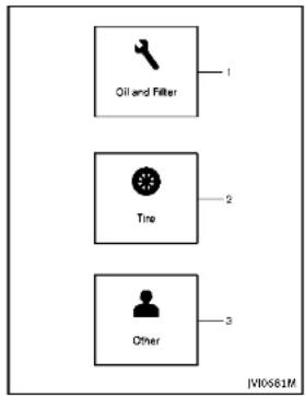
text_image
Oil and Filter 1 Tire 2 3 Other IV10561MINDICATORSFORMAINTENANCE
Forsettingtheindicatorsformaintenance, seethelnfinitiInTouchOwner'sManual.
- Engineoilandfilterreplacement indicator
This indicator appears when the customer settime comes for changing the engine oil and filter. You can set or reset the distance for changing the engine oil and filter.
- Tirereplacement indicator This indicator appears when the customer set distance comes for replacing tires. You can set or reset the distance for replacing tires.

WARNING
The tiriereplacementindicatorisnota substituteforregulartirechecks, including tirepressurechecks. See "Changingwheels and tires" (P.8-37). Many factors including tireinflation, alignment, driving habits and road conditions affect treewearand when tires should bereplaced. Setting the tire replacementindicatorforacertain driving distance does not mean your tires will last that long. Usethetirereplacement indicator as aguideonly and always perform regular tire checks. Failure to perform irregular tire checks, including tire pressurecheckscould result in tire failure. Serious vehicle damage
2-26 Instrumentsandcontrols
couldoccurandmayleadtoacollision, which could result in serious personal injury or death.
- Other indicator
This indicator appears when the customer settime comes for replacing items other than the engine oil, oil filter and tires. You can set or reset the distance for replacing the items.

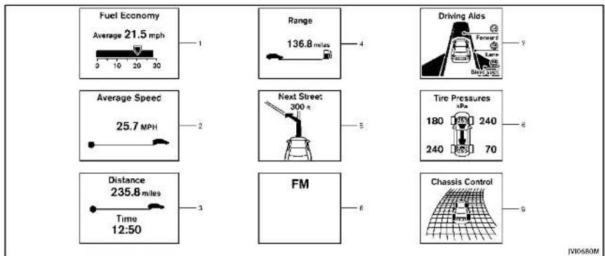
other
| Metric | Value | | :--- | :--- | | Fuel Economy (Average) | 21.5 mph | | Range | 136.8 miles | | Driving Alas (Forward) | 7 | | Average Speed (Average Speed) | 25.7 MPH | | Next Street (300 km) | 5 | | Tire Pressures (kPa) | 6 | | Distance (Time 12:50) | 3 | | FM | 6 | | Chassis Control (Chassis Model) | 9 |
Instrumentsandcontrols2·27
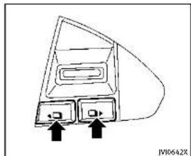
natural_image
Diagram of a device rear panel with two buttons and an arrow pointing to the front panel (no text or symbols present)TRIPCOMPUTER
Switchesforthetripcomputerarelocated ontherightsideofthesteeringwheel.To operatethetripcomputer.pushthe switchesasshownabove.
Eachtimethe or switch is pushed, the display will change.
Thedisplayitemsfortripcomputerare changedonthelowerdisplay.Fordetails, seethelnfinitiInTouchOwner'sManual.
- Currentfuelconsumption and averagefuelconsumption(MPG, l (liter)/100kmorkm/l)
Currentfuelconsumption:
The current fuel consumption modes shows the current fuel consumption.
Averagefuelconsumption:
Theaveragefuelconsumptionmodeshows theaveragefuelconsumptionsincethe lastreset.Resetingisdonebypushingthe
orswitchforlongerthan1 second.
Theaveragefuelconsumptionisalsoreset onthelowerdisplay.SeetheInfiniti InTouchOwner'sManual.
Thedisplayisupdatedevery30seconds. Ataboutthefirst1/3mile(500m)aftera reset,thedisplayshows“——”.
2.Averagespeed(MPHorkm/h)
Theaveragespeed modeshowsthe averagevehiclespeedsincethelastreset. Resettingisdonebypushingthe or
switch for longer than 1 second. The display is updated every 30 seconds. The first 30 seconds after a reset, the display shows "—".
- Elapsed time and tripodometer (mileorkm)
Elapsedtime:
Theelapsedtimemodeshowsthetime sincethelastreset. Resettingisdoneby pushingthe ▶ orswhforlonger than1second.(Thetripodometerisalso resetatthesametime.)
Tripodometer:
Thetripodometermodeshowsthetotal distancethevehiclehasbeendrivensince thelastreset. Resettingisdonebypushing the ◄ or ▶ switchforlongerthan1 second.(Theelapsedtimeisalsoresetat thesametime.)
- Distancetoempty(dte—mileor km)
Thedistancetoempty(dte)modeprovides youwithanestimationofthedistancethat canbedrivenbeforerefueling. Thedteis constantlybeingcalculated, basedonthe amountoffuelinthefueltankandthe actualfuelconsumption.
Thedisplayisupdatedevery30seconds.
Thedtemodeincludesa low rangewarning feature.Ifthefuellevelislow,thewarning isdisplayedonthescreen.
2-28Instrumentsandcontrols
Whenthefuelleveldropsevenlower,the dtedisplaywillchangeto“——”.
- If the amount off fuel added small, the display just before the ignition switch is pushed to the OFF position may continue to be displayed.
- Whendrivinguphillorroundingcurves, thefuelinthetankshifts, which may momentarilychangethedisplay.
5. Navigation(ifsoequipped)
Whentherouteguidanceissetinthe navigationsystem,thisitemshowsthe navigationrouteinformation.
Formoredetails, seethelnfinitilnTouch Owner'sManual.
6.Audio
Theaudiomodeshowsthestatusofaudio information.
Formoredetails,seethelnfinitiInTouch Owner'sManual.
7. Drivingaids(ifsoequipped)
The driving aids modeshow the operating condition for the following systems.
■LaneDepartureWarning(LDW)
•LaneDeparturePrevention(LDP)
- BlindSpotWarning(BSW)
●BlindSpotIntervention ^TM (BSI)
•DistanceControlAssist(DCA)
●Forwardemergencybraking
●Predictiveforwardcollisionwarning
Formoredetails,see"LaneDeparture
Warning(LDW)system/LaneDeparture Proportion(LBP)system"(R 5-30) #Blind
Prevention(LDT)system (1.5-30), Blind SpotWarning/BlindSpotIntervention TM/
Back-upCollisionInterventionsystems"
(P.5-37). "DistanceControlAssist(DCA)
system"(P.5-79), "Forwardemergency
brakingsystem" (P.5-89) and Predictive forwardcollisionwarningsystem"(P.5-94).
8. Tirepressure
Thetirepressuremodeshowsthepressure
of all four tires while the vehicle is driven.
SeethelInfinitiInTouchOwner'sManualfor thedisplaysettings.
Whenthe"TirePressureLow-AddAir"or
"FlatTire-Visitdealer" warningappears,
thedisplaycanbeswitchedtot
or
9. Chas sis control
When Active Lane Control (if so equipped)
or the active trace control system is
operated, it shows the operating condition.
See"ActiveLaneControl"(P.5-24)and
"Activetracecontrol"(P.5-110)formore
details.
10. Warningcheck
Thepresentwarningsaredisplayed.Ifno
warningispresent,"NoWarning"isdis-
played.

text_image
10:32 AM 80°F ① ② JV0675MCLOCKANDOUTSIDEAIRTEM- PERATURE
Theclock ① andoutsideairtemperature ② aredisplayedontheuppersideofthe vehicleinformationdisplay.
Clock
Theclockcanbeadjustedonthelower display.SeetheInfinitiInTouchOwner's Manual.
Outside air temperature (°F or °C) The outside air temperature is displayed in °F or °C in the range of -22 to 131°F (-3 to 55°C).
2-30 instruments and controls
Theoutsidetemperaturesensorislocated infrontoftheradiator. Thesensormaybe affectedbyroadorengineheat, wind directionsandotherdrivingconditions. Thedisplaymaydifferfromtheactual outsidetemperatureorthetelempature displayedonvariousssignsorbillboards.
SECURITYSYSTEMS

natural_image
Diagram of a car with concentric circular patterns and a central object, no text or symbols presentYourvehiclehastwotypesofsecurity systems,asfollows: •Vehiclesecuritysystem •INFINITIVehicleImmobilizerSystem Theseurityconditionwillbeshownbythe securityindicatorlight.

VEHICLESECURITYSYSTEM
The vehicle security system provides visual and audio alarms signals if someone opens the doors, hood, or trunk lid when the system isarmed. It is not, however, a motion detection typesystem that activates when a vehicle is moved or when a vibration occurs.
Thesystemhelpsdetervehicletheftbut cannotpreventit, norcanitpreventthe theftofinteriororexteriorvehiclecomponentsinallsituations. Alwayssecureyour vehicleevenifparkingforabriefperiod. NeverleaveyourIntelligentKey(s)inthe vehicle, andalwayslockitwhenunattended. Beawareofyoursurroundings, andparkinsecure, well-litareaswhenever possible.
Manydevicesofferingadditionalprotection,suchascomponentlocks,identificationmarkers,andtrackingsystems,areavailabletautosupplystoresandspecialtyshops.YourINFINITretailermayalsooffersuchequipment.Checkwithyourinsurancecompanytoseeifyoumaybeeligiblefordiscountsforvarioustheftprotectionfeatures.
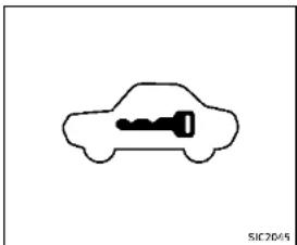
natural_image
Simple line drawing of a car with a key inside, no text or symbols presentHowtoarmthevehiclesecurity system
1.Closeallwindows.
Thesystemcanbearmedevenifthe windowsareopen.
-
PushtheignitionswitchtotheOFF position.
-
Removethe Intelligent Key from the vehicle.
-
Close all doors, hood and trunk. Lock all doors. The doors can be locked with the Intelligent Key, door handle request switch, power door lock switch or mechanical key.
-
Confirm that these security indicator light comeson. These security indicator light stay on for about 30 seconds. The vehicle security system is now prepared. After about 30 seconds the vehicle security system automatically shifts into the armed phase. The security light begins of flash once every approximately 3 seconds. If, during this 30 second pre- armit time period, the door is unlocked, or the ignitions which is pushed to ACCorON, the system will notarm.
Evenwhenthedriverand/orpassengers areinthevehicle,thesystemwillactivate withalldoors,hood,andtrunklidlocked withtheignitionswitchintheLOCK position.Whenpushingtheignitionswitch totheACCorONposition,thesystemwill bereleased.
Vehiclesecuritysystemactivation Thevehiclesecuritysystemwillgivethe followingalarm:
●Theheadlightsblinkandthehorn soundsintermittently.
●Thealarmautomaticallyturnsoffafter approximately1 minute. However, the alarmreactivatesifthevehicleis
Instrumentsandcontrols2·31
tamperedwithagain.
Thealarmisactivatedby:
- Unlockingthedoororopeningthetrunk lidwithoutusingthebuttononthe IntelligentKey,thedoorhandlerequest switch,onelouchunlocksensororthe mechanicalkey.(Evenilthedooris openedbyreleasingthedoorinside lockknob,thealarmwillactivate.)
- Openingthehood.
Howtostopanactivatedalarm Thealarmwillstopbyunlockingadoorby pushingtheUNLOCKbuttonontheIntelligentKey,thedoorhandlerequestswitch, touchingtheonetouchunlocksensor usingthemechanicalkey. Thealarmwill notstopiftheignitionswitchispushedto theACCorONposition.
If the system does not operate as described above, have it checked by an INFINIT retailer.
The INFINITE Vehicle Immobilizer System will not allow the engine to start without the use of the registered Intelligent Key. Never leavethese keys in the vehicle.
FCCNotice:
ForUSA:
ThisdevicecomplieswithPart15ofthe FCCRules.Operationissubjecttothe followingtwoconditions:(1)Thisdevice maynotcauseharmfulinterference,and (2)thisdevicemustacceptanyinterferencereceived,includinginterferencethat maycauseundesiredoperation.
NOTE:
Changesormodificationsnotexpressly approvedbythepartyresponsiblefor compliancecouldvoidtheuser'sauthority tooperatetheequipment.
ForCanada:
This device complies with RSS-210 of Industry Canada. Operation is subject to the following two conditions: (1) this device may not cause interference, and (2) this device must accept any interference, including interference that may
causeundesiredoperationofthedevice.
2-32 Instrumentsandcontrols

natural_image
Simple line drawing of a car with a key inside, no text or symbols presentSecurityindicatorlight
Theseurityindicatorlightislocatedon themeterpanel.Itindicatesthestatusof theINFINITIVehicleImmobilizerSystem.
Thelightblinksaftertheignitionswitch wasintheLOCK,ACCorOFFposition.This functionindicatethesecuritysystems equippedonthevehicleareoperational.
IftheINFINITIVehicleImmobilizerSystem ismalfunctioning, thislightwillremainon whiletheignitionswitchisintheON position.
Ifthelightstillremainsonand/orthe enginewillnotstart,seeanINFINITI retailerforINFINITIVehicleImmobilizer Systemserviceassoonaspossible. PleasebringallIntelligentKeysthatyou havewhenvisitinganINFINITIretailerfor service.

- Donotoperatethewashercontinuously formorethan30seconds.
- Donotoperatethewasherifthe reservoirtankisempty.
- Donotfillthewindowwasherreservoir tankwithwasherfluidconcentratesat fullstrength. Somemethylalcohol basedwasherfluidconcentratesmay permanentlystainthegrilleifspilled whilefillingthewindowwasherreservoirtank.
- Pre-mixwasherfluidconcentrateswith watertothemanufacturer's recommendedlevelsbeforepouringthefluid intothewindowwasherreservoirtank. Donotusethewindowwasherreservoir
Instrumentsandcontrols2-33
tanktomixthewasherfluidconcentrate andwater.
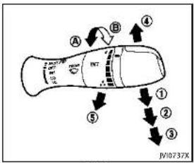
text_image
A B ④ ⑤ ① ② ③ JV10737X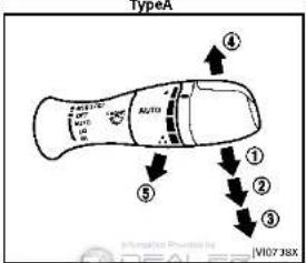
text_image
TypeX 4 5 ① ② ③ ④ A2/TA V107 38X Information Powered by IDEALER [VI07 38X]Type B
The windshieldwiper and washer operates when the ignition switch is in the ON position.
Pushtheleverdowntooperatethewiper atthefollowingspeed:
① INT(TypeA)—intermittentoperation can beadjusted by turning the knob toward A (Slower) or B (Faster). Whenthespeedsensingwiperinterval functionisturnedon, the intermittentoperations speed varies in accordance with the vehiclespeed. (Forexample, whentheviclespeed is high, the intermittent operation speed will be faster.) Toturnthis functionon and off, seethelnfiniti InTouchOwner's Manual.
① AUTO(TypeB)—Formodelswiththe rain-sensingautowipersystem,see "Rain-sensingautowipersystem" (P.2-35).
② LO—continuousslowspeedoperation
③ HI—continuoushighspeedoperation
④ MIST—onesweepoperationofthe wiper
Pullthelevertowardyou ③ looperalethe washer. Thenthewiperwillalsooperate severaltimes.
2-34Instrumentsandcontrols
Pullingupthewiperarm:
Thewiperarmshouldbeintheupposition whenreplacingthewiper.
Topullupthewiperarm,pushup ④ twice whentheignitionswitchisintheOFF positionwithin1minute.Thewiperoperationstopsinmid-operationandthewiper armcanbepulledup.
TheshiftlevershouldbeintheP(Park) position.
Toretumthewiperam, placethewiper arminthedownpositionandoperatethe wiperswitchonce.

CAUTION
Donotoperatethewindshieldwiperwhile thewiperarmispulledup. Thewiperarm maybedamaged.
Wiperdripwipesystem:
Thewiperwillalsooperateonceabout3 secondsafterthewasherandwiperare operated.Thisoperationistowipewasher fluidthathasdrippedonthewindshield.

text_image
① ② ③ AUTO JY10735XRAIN-SENSINGAUTOWIPERSYSTEM(ifsoequipped)
Therain-sensingautowipersystemcan automaticallyturnonthewipersand adjustthewiperspeeddependingonthe rainfallandthevehiclespeedbyusingthe rainsensorlocatedontheupperpartof thewindshield.
Tosettherain-sensingautowipersystem, pushtheleverdowntotheAUTOposition
①. The wiper will sweep once while the ignition switch is in the ON position.
The rain sensor sensitivity level can be adjusted by turning the knob toward ②
(High)ortoward ③ (Low).
- High—Highsensitiveoperation - Low—Lowsensitiveoperation
Toturntherain-sensingautowipersystem off, pushupthelevertotheOFFposition, orpulldownthelevertotheLOorHI position.

CAUTION
Donottouchtherainsensorandaroundit whenthewiperswitchisintheAUTO positionandthelnitionswitchisinthe ONposition. Thewipersmayoperateun-expectedlyandcausetoaninjuryorawiper damage.
- Therain-sensingautowipersareintendedforuseduringrain.Iftheswitch isleftintheAUTOposition,thewipers mayoperateunexpectedlywhendirt, fingerprints,oilfilmorinsectsare stuckonoraroundthesensor.The wipersmayalsooperatewhenexhaust gasormoistureaffecttherainsensor.
- Therain-sensingautowipersmaynot operateifraindoesnothittherain sensorevenlfitisraining.
Instrumentsandcontrols2·35
- Whenthewindshieldglassiscoated withwaterrepellent,thespeedofthe rain-sensingautowipersmaybehigereventhoughtheamountofthe rainfalllissmall. - Besuretoturnofftherain-sensing autowipersystemwhenyouseacar wash. - Usinggenuinewiperbladesirecommendedforproperoperationofthe rain-sensingautowipersystem.(See "Windshieldwiperblades"(P.8-20)for wiperbladeplacement.)
REARWINDOWANDOUTSIDEMIRROR
DEFROSTERSWITCH

text_image
① DUAL ② JV00643XTodefog/defrosttherearwindowglass andoutsidemirrors,starttheengineand pushtheswitch ① on.Theindicatorlight ② willcomeon.Pushtheswitchagainto turnthedefrosteroff.
It will automatically turnoff in approximately 15 minutes.
CAUTION
When cleaning the inner side of the rear window, be careful not to scratch or damage the rear window defroster.
HEADLIGHTANDTURNSIGNALSWITCH
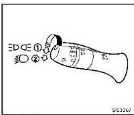
text_image
① ② S/C3267HEADLIGHTSWITCH
Lighting
① Turntheswitchtothe position: Thefrontparking, sidemarker, tail and licenseplatelightswillcomeon. ② Turntheswitchtothe position: Headlightswillcomeonandallthe otherlightsremainon.

text_image
① SIC3268Autolightsystem
Theautolightsystemallowstheheadlights to besetso they turn on and off automatically.
Tosettheautolightsystem:
-
Makesuretheheadlightswitchisinthe AUTOposition ①.
-
PushtheignitionswitchtotheON position.
-
The autolightsystemautomatically turnstheheadlightsonandoff.
Toturntheautolightsystemoff, turnthe switchtotheOFF, orposition.
Theautolightsystemcanturnonthe headlightsautomaticallywhenitisdark andturnofftheheadlightswhenitislight. Theheadlightswillturnonautomaticallyat twilightorinrainyweather(whenthe windshieldwiperisoperatedcontinuously).
If theignitionswitchispushedtotheOFF positionandoneofthedoorsisopened and thisconditioniscontinued,theheadlightsremainonfor5minutes.
Automaticheadlightsoffdelay:
Youcankeeptheheadlightsonforupto 180secondsafteryoupushtheignition switchtoOFFandopenanydoorthenclose allthedoors.
Youcanadjusttheperiodoftheautomatic headlightsoffdelayfrom0seconds(OFF) to180seconds.Thefactorydefaultsetting is45seconds.
Forautomaticheadlightsoffdelaysetting, seethelnfinitilnTouchOwner'sManual.
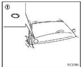
natural_image
Simple line drawing of a car with wheels and a handle, no text or symbols presentBesurenottoputanythingontopofthe photosensor ① locatedonthetopofthe instrumentpanel.Thephotosensorcontrolstheautolight;ifitiscovered,the photosensorreactsasifitisdarkandthe headlightswillilluminate.

Instrumentsandcontrols2-37
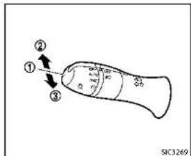
text_image
① ② ③ SIC3269Headlightbeamselect
① Toselectthelowbeam, putthelever intheneutralpositionasshown.
② Toselectthehighbeam, push the leverforwardwhiletheswitchisinthe position. Pullitbacktoselectthe lowbeam.
③ Pullingthelevertowardyouwillflash theheadlighthighbeamevenwhen theheadlightswitchisintheOFF position.
Highbeamassist(ifsoequipped)
Thehighbeamassistsystemwilloperate whenthevehicleisdrivenatspeedsof approximately22MPH(35km/h)and above.Ifanoncomingvehicleorleading vehicleappearsinfrontofyourvehicle whentheheadlighthighbeamison,the headlightwillbeswitchedtothelowbeam automatically.
Precautionsonhighbeamassist:
WARNING
●Thehighbeamassistsystemisa conveniencebutilisnotasubstitute for safedrivingoperation. Thedriver shouldremainalertataltimes,ensure safedrivingpracticesandswitchthe highbeamsandlowbeammanually when necessary.
●Thehighbeamorlowbeammaynot switchautomaticallyunderthefollowing conditions.Switchthehighbeamand lowbeammanually.
— During bad weather (rain, fog, snow, wind, etc.).
- When a light source similar to a
headlightortaillightisinthe vicinityofthevehicle.
— Whentheheadlightsoftheoncomingvehicleortheleadingvehicleare turnedoff,whenthecolorofthelight isaffectedduetoforeignmaterials onthelights,orwhenthelightbeam isoutofposition.
— Whenthereisasudden,continuous changeinbrightness.
— Whendrivingonaroadthatpasses overrollinghills, oraroadthathas leveldifferences.
— Whendrivingonaroadwithmany curves.
— Whenasignormirror-likesurfaceis reflectingintenselighttowardsthe frontofthevehicle.
— Whenthecontainer, etc. being towed by leading vehicle is reflecting intenselight.
— Whenaheadlightonyourvehicleis damagedordirty.
— Whenthevehiclelsleaningatan angleduetoapuncturedtire, being towed, etc.
2-38Instrumentsandcontrols
- Thetimingofswitchingthelowbeam andhighbeammaychangeunderthe followingsituations.
— Thebrightnessoftheheadlightsof theoncomingvehicleorleading vehicle.
— Themovementanddirectionofthe oncomingvehicleandtheleading vehicle.
— Whenonlyonelightontheoncomingvehicleortheleadingvehicleis illuminated.
— Whentheoncomingvehicleorthe leadingvehicleisatwo-wheeled vehicle.
— Roadconditions(incline,curve,the roadsurface,etc.).
— Thenumberofpassengersandthe amountofluggage.

text_image
① ② JV10686XHighbeamassistoperations:
Toactivate the high beam assists system,
turntheneadlightswitchtotheAUTO position ④ andpushtbeleverforward
position (1) and thus construct vector forward (highbeam position). The highbeam mass
indicatorlightinthemeterwillilluminate whiletheheadlightsaretumedon.
If the high beam assist indicator light does not illuminate in the above condition, it may indicate that the system is not functioning properly. Havethesystem checked by an INFINITI retailer.
When the vehicle speed lowers to less than approximately 17 MPH (27 km/h), the headlight remains the low beam.
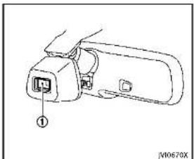
natural_image
Line drawing of a device with an internal connector labeled (no text or symbols present)Ambientimagesensormaintenance:
Theambientimagesensor ① forthehigh
beamassistsystemislocatedinfrontor theinsidemirror.Tokeeptheproper
operationofthehighbeamassistsystem
andpreventasystemmalfunction, besure toobservethefollowing:
●Alwayskeepthewindshieldclean.
- Donotattachasticker(including transparentmaterial)orinstallan accessoryneartheambientimage sensor.
- Donotstrikeordamagetheareas aroundtheambientimagesensor.Do nottouchthesensorlensthatis
locatedontheambientimagesensor. Iftheambientimagesensorisdamaged duetoanaccident,contactanINFINITI retailer.
Batterysaversystem
Achimewillsoundandthelightreminder warningwillappearinthevehicleinformationdisplaywhenthedriversidedooris openedwiththelightswitchinthe or \$positionandtheignitionswitchinthe ACC,OFFForLOCKposition.
Whentheheadlightswitchisinthe positionwhiletheignitionswitchisin theONposition,thelightswillautomaticallyturnoffafteraperiodoftimewhen theignitionswitchhasbeenpushedtothe OFFposition.
When the headlight switch remains in the spec or position after the lights automatically turn off, the light will turn on when the ignition switch is pushed to the ON position.

CAUTION
- Whenyouturnontheheadlightswitch againafterthelightsautomaticallyturn
off,thelightswillnotturnoffautomatically.Besuretoturnthelight switchtotheOFFpositionwhenyou leavethevehicleforextendedperiodsof time,otherwisethebatterywillbe discharged.
- Neverleavethelightswitchonwhenthe engineisnotrunningforaperiodoftime eveniftheheadlightsturnoffautomatically.
Daytimerunninglightsystem
Thedaytimerunninglightsautomatically illuminatewhentheengineisstartedwith theparkingbrakereleased. Thedaytime runninglightsoperatewiththeheadlight switchintheOFF,AUTOor position. Turntheheadlightswitchtothe positionforfullilluminationwhendriving atnight.
If the parking brake is applied before the engine is started, the daytime running lights donotilluminate. The daytime running lightsilluminate on the parking brake is released. The daytime running lights will remain on until the ignition switch is pushed to the OFF position.

WARNING
Whenthedaytimerunninglightsystemis active, taillightsonyourvehiclearenonton. It is necessary at dusktoturnonyour headlights. Failure to dosocould cause an accident in juring yourself and others.
AdaptiveFrontlightingSystem (AFS)(ifsoequipped)
The Adaptive Frontlighting System (AFS) will automatically adjust the headlights (low beam) toward the turning direction to improve the driver's view. When the headlight switch is ON and the driver operates the steering wheelinatum, the AFS system will be activated.
TheAFSwilloperate:
- whentheheadlightswitchisON.
- whentheshiftleverisinanayposition
otherthanP(Park)orR(Reverse). - whenthevehicleisdrivenatabove3MPH(5km/h)fortheleft-sideheadlight.Notethatheright-sidelowbeamheadlightwillswivelbuttheleft-sideheadlightwillnotswivelwhenthevehicleisbelow3MPH(5km/h)and
2-40Instrumentsandcontrols
thesteeringwheelisturned. AFSwillalsoadjusttheheadlighttoa properaxisautomatically,dependingon thenumberofoccupantsinthevehicle,the loadthevehicleiscarryingandtheroad conditions.
If the AFS warning appears in the vehicle information display after the ignition switch has been pushed to the ON position, this may indicate that the AFS is not functioning properly. Have the system checked by an INFINITretailer. When the engine is started, the headlights will liberate to check the system condition. This is not a malfunction.

text_image
TRIP RESET A B JV0644X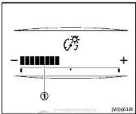
text_image
Diagram showing a circuit or signal path with labeled components and directional indicatorsInstrumentbrightnesscontrol
Theinstrumentbrightnesscontrolswitch canbeoperatedwhentheignitionswitch isintheONposition.Whentheswitchis operated.thevehicleinformationdisplay switchchestothebrightnessadjustment mode.
Pushthe+sideoftheswitch Ⓐ to brightentheinstrumentpanellights. The bar ① movestothe+side.
Pushthe-sideoftheswitch ⑧ todimthe instrumentpanellights.Thebar ① moves tothe-side.Whenthebrightnesslevel reachestheminimum,theinstrument panellightswillturnoffduringthenight-time.
Whenthebrightnesslevelreachesthe maximumorminimum, abeepwillsound. Thevehicleinformationdisplayreturnsto thenormaldisplayunderthefollowing conditions:
- when the instrument brightness control switch is not operated from more than 5 seconds.
- whenthe orswitchontheright sideofthesteeringswitchispushed.
Instrumentsandcontrols2·41

text_image
① ② ① ② SIC3271TURNSIGNALSWITCH
① Turnsignal
Movetheleverupordowntosignalthe turningdirection. Whentheturniscompleted, theturnsignalscancelautomatically.
② Lanechangesignal
Toindicatealanechange, movethelever upordowntothepointwherelightsbegin flashing.
If the lever is moved back right after moving up or down, the light will flash 3 times.
2-42 Instrumentsandcontrols
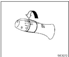
text_image
SIC3272FOGLIGHTSWITCH
Toturnthefoglightson,turntheheadlight switchtothe 10 position,thenturnthe switchtothe 20 position.Toturnthem off,turntheswitchtotheOFFposition. Theheadlightsmustbeonforthefog lightstooperate.

HORN

natural_image
Diagram of a car steering wheel with an arrow indicating clockwise direction (no text or symbols)Tosoundthehom, pushthecenterpad area of the steering wheel.

WARNING
Donotdisassemblethehorn.Doingso couldaffectproperoperationofthesupplementalfrontairbagsystem.Tamperingwith thesupplementalfrontairbagsystemmay resultinseriouspersonalinjury.
VEHICLEDYNAMICCONTROL(VDC)OFF SWITCH
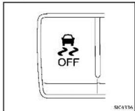
text_image
OFF SIC4336The vehicles should be driven with the VehicleDynamicControl(VDC) system on for most driving conditions.
Ifthevehicleisstuckinmudorsnow,the VDCsystemreducestheengineoutputto reducewheelspin.Theenginespeedwill bereducedeveniftheacceleratoris depressedtothefloor.Ifmaximumengine powerisneededtofreeastuckvehicle, turntheVDCsystemoff.
ToturnofftheVDCsystem.pushtheVDC OFFswitch.The indicatorlightwill illuminate.
PushtheVDCOFFswitchagainorrestart theenginetoturnonthesystem.(See
"VehicleDynamicControl(VDC)system" (P.5-108.)

POWEROUTLET
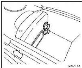
natural_image
Technical line drawing of a mechanical component with no visible text or symbolsThepoweroutletsarelocatedinthecenter console.

CAUTION
•Theoutletandplugmaybehotduringor immediatelyafteruse.
- Donotusewithaccessorlesthatexceed a12volt,120W(10A)powerdraw.Do notusedoubleadaptersormorethan oneelectricalaccessory.
- Usepoweroutletwiththeenginerun- ningtoavoiddischargingthevehicle battery.
Instrumentsandcontrols2-43
ASHTRAY(ifsoequipped)STORAGE
- Avoidusingpoweroutletwhentheair conditioner,headlightsorrearwindow defrosterlson.
- Thispoweroutletisnotdesignedforuse withacigarettelighterunit.
- Pushthepluginasfarasitwillgo.If goodcontactisnotmade,theplugmay overheatortheinternaltemperature fusemayblow.
- Beforeinsertingordisconnectingaplug, besuretheelectricalaccessorybeing usedisturnedOFF.
- When not in use, besuretoclosethe cap. Donotallowwateroranyliquid to contact the outlet.
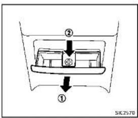
text_image
② ③ ① SIC2570CUPHOLDERS

CAUTION
- Avoid abrupt starting and braking when the cupholder is being used to prevent spilling the drink. If the liquid is shot, it cans caldy our your passenger.
- Useonlysoftcupsinthecupholder. Hardobjectscaninjureyouinan accident.
REAR
Toopentheashtraylid, pull

Toemptytheashtray,pushdown

pullout.
2-44Instrumentsandcontrols

Information Policy by: DEALER
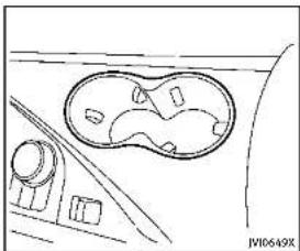
natural_image
Line drawing of a car interior with a circular vent and dashboard (no text or symbols)Front
Opentheliodofthereararmresttousethe cupholder.

natural_image
Line drawing of a car interior showing the dashboard and seat area (no text or symbols)Rear


natural_image
Pure technical line drawing of a mechanical component or bracket (no text or symbols)SOFTBOTTLEHOLDER

CAUTION
- Donotusebottleholderforanyother objectsthatcouldbethrownaboutin thevehicleandpossiblyinjurepeople duringsuddenbrakingoranaccident. - Donotusebottleholderforopenliquid containers.
Instrumentsandcontrols2-45

text_image
JW10651XSUNGLASSESHOLDER

WARNING
Keepthesunglassesholderclosedwhile drivingtopreventanaccident.
Toopenthesunglassesholder, pushthe lid.

CAUTION
- Donotuseforanythingotherthan glasses.
- Donotleaveglassesinthesunglasses holderwhileparkingindirectsunlight. Theheatmaydamagetheglasses.
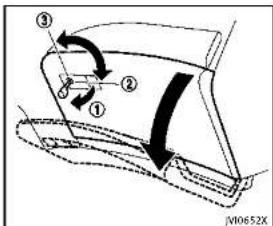
text_image
Diagram showing a car door mechanism with numbered parts and directional arrows indicating motion or movement.GLOVEBOX

WARNING
Keepgloveboxlidclosedwhiledrivingto helppreventinjuryinanaccidentora suddenstop.
Toopentheglovebox, pullthehandle ①. Toclose, pushthelidin until the lock latches.
Tolock ①/unlock ③ theglovebox, use themechanicalkey. Forthemechanicalkey usage, see "Keys" (P.3-2).
2-46Instrumentsandcontrols
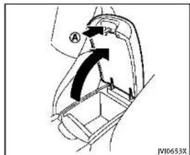
text_image
A JW10653XCONSOLEBOX
Toopentheconsolebox, pushuptheknob (A) andpullupthelid.
Toclose, pushtheliddownuntillatched.
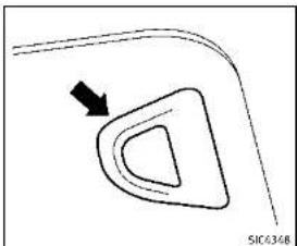
natural_image
Simple line drawing of a curved shape with an arrow indicating direction (no text or symbols)CARDHOLDER
Thecardholderislocatedonthedriver'sor passenger'ssunvisor.
Tousethecardholder, slidethecardinthe cardholder.
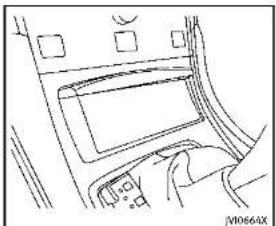
natural_image
Line drawing of a hand pressing a component on a device (no text or symbols visible)STORAGEBOX
Toopen, pushthestorageboxlid.
Donotplacevaluableitemsinthestorage
BOX.
Donotusethestorageboxasanashtray.

Instrumentsandcontrols2·47
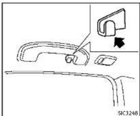
natural_image
Diagram of a car door handle and seat assembly with an arrow indicating a component (no text or symbols present)COATHOOKS
Thecoathooksareequippedbesidethe rearpersonallights.

CAUTION
Donotplaceitemswhicharemorethan2lb (1kg)onthehook.

natural_image
Technical line drawing of a car front panel with a dial indicator (no text or symbols)TRUNKHOOKS

WARNING
●Alwaysmakesurethatthecargois properlysecured. Use the suitable or proper names and hooks.
• Unsecuredcargocanbecomedangerous inanaccidentorsuddenstop.

CAUTION
Donotapplyatotalloadofmorethan22lb (10kg)toasinglehook.
2-48Instrumentsandcontrols

DEALER
WINDOWS
POWERWINDOWS

WARNING
- Makesurethatallpassengershavetheir hands,etc.insidethevehiclewhileitis inmotionandbeforeclosingthewindows.Usethewindowlockswitchto preventunexpecteduseofthepower windows.
- Donotleavechildrenunattendedinside thevehicle. Theycouldunknowingly activateswitchesorcontrolsandbecometrappedinthewindow. Unattendedchildrencouldbecomeinvolved inseriousaccidents.
The powerwindowsoperatewhen the ignitionswitchisintheONpositionorfor about45secondsaftertheignitionswitch is pushedtotheOFFposition.If the driver'sorfrontpassenger'sdooris openedduringthisperiodofabout45 seconds,powertothewindowsiscanceled.

text_image
A B C D E F G H I J K L M N O P Q R S T U V W X Y Z VA0740X1.Driversidewindow
2.Frontpassengersidewindow
-
Rearleftpassengersidewindow
-
Rearightpassengersidewindow
-
Windowlockbutton
Mainpowerwindowswitch(driver's side)
Toopenorclosethewindow,pushdown
Ⓐ orpullup Ⓑ theswitchandholdit.
Themainswitch(driversideswitches)will open or close all the windows.

Lockingpassengers'windows
Whenthelockbutton © ispushedin,only
theriversidewindowcanbeopenedor closed.Pushitinagaintocancel.
Instrumentsandcontrols2-49

natural_image
Diagram of a car interior with a control panel and directional arrows indicating movement (no text or symbols)Passengersidepowerwindow switch
The passengers sides switch will open or close only the corresponding window. To open or closet how window, pushdown or pullup the switch and hold it.

natural_image
Top-down line drawing of a boat with compartments and directional arrows indicating flow or movement (no text or symbols)Automaticoperation
Tofullyopenorclosethewindow, completelypushdownorpulluptheswitch andreleaseit; itneednotbeheld. The windowwill automaticallyopenorcloseall theway. Tostopthewindow, justpushor liftheswitchintheoppositedirection. Alightpushorpullontheswitchwillcause thewindowtoopenorcloseuntilthe switchisreleased.
Autoreversefunction
WARNING
Therearesomesmalldistancesimmediately beforetheclosedpositionwhichcannot be detected.Makesurethatallpassengers havetheirhands,etc.,insidethevehicle beforeclosingthewindow.
If the control unit detects something caught in the window as it is closing, the window will be immediately lowered. The autoreverse function can be activated when the window is closed by automatic operation when the ignition switch is in the ON position or for 4 seconds after the ignition switch is pushed to the OFF position.
Depending on the environment driving conditions, the autoreverse function may be activated if an impactor loads similar to something being caught in the window occurs.
Ifthewindowsdonotcloseautomatically
If the power window automatic function
2-50Instrumentsandcontrols
MOONROOF(ifsoequipped)
(closingonly)doesnotoperateproperly, performthefollowingproceduretoinitializethepowerwindowsystem.
- PushtheignitionswitchtotheON position.
2.Closethedoor.
-
Openthewindowcompletelybyoperatingthepowerwindowswitch.
-
Pull the power window switch and hold it to close the window, and then hold the switch more than 3 seconds after the window is closed completely.
-
Releasethepowerwindowswitch. Operatethewindowbytheautomatic function to confirm the initialization is complete.
-
Perform steps2 through 5 above for other windows.
If the power window automatic function does not operate properly after performing the procedure above, have your vehicle checked by an INFINIT retailer.
WARNING
•Inanaccidentyoucouldbethrownfrom thevehiclethroughanopenmoonroof. Alwaysuseseatbeltsandchildrestraints.
- Donotallowanyonetostandupor extendanyportionoftheirbodyoutof themoonroofopeningwhilethevehicle isinmotionorwhilethemoonroofis closing.
CAUTION
-Removewaterdrops, snow, iceorsand from themoonroof before opening.
- Donotplaceanyheavyobjectonthe moonrooforsurroundingarea.
AUTOMATICMOONROOF
Themoonroofonlyoperateswhenthe ignitionswitchisintheONposition.
The automatic moonroof is operational for about 45 seconds, even if the ignition switch is pushed to the OFF position. If the driver's door or the passenger's door is opened during this period of about 45 seconds, power to the moon roof is canceled.

Instrumentsandcontrols2·51
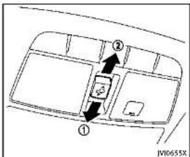
text_image
Diagram showing a vehicle interior with labeled parts and directional arrows indicating movement or flow.Sunshade
Thesunshadewillopenautomatically whenthemoonroofisopened. However, itmustbeclosedmanually.
Tiltingthemoonroof
Totiltup,firstclosethemoonroof,then pushtheswitchtothetiltupposition andreleaseit;itneednotbeheld.Totilt downthemoonroof,pushtheswitchtothe tiltdownposition ②.
Slidingthemoonroof
Tofullyopenorclosethemoonroof, push theswitchtotheopen ② orclose ①
positionandreleaseit;itneednotbeheld. Theroofwillautomaticallyopenorcloseall theway. Tostoptheroof, pushtheswitch oncemorewhileitisopeningorclosing.
OperatingmoonroofwithIntelligent Key(ifsoequipped)
The moonroofcanbeopenedbypushing theUNLOCKbuttonontheIntelligentKey. Thisfunctionwillnotoperatewhilethe moonrooftimerisactivatedorwhenthe moonroofneedtobeinitialized.Fordetails abouttheIntelligentKeybuttonusage,see "Howtouseremotekeylessentrysystem" (P.3-15).
Opening:
Toopenthesunroof.pushtheUNLOCK buttononthelIntelligentKeyforabout3 secondsafterthedoorisunlocked.
Tostopopening, releasethe button.
a button.

Autoreversefunction

WARNING
Therearesomesmalldistancesimmediately beforetheclosedpositionwhichcannot be detected.Makesurethatallpassengers havetheirhands,etc.,insidethevehicle beforeclosingthemoonroof.
If the control unit detects something caught in themoonroof when it is closing, the moonroof will be immediately opened. The autoreverse function can be activated when themoonroof is closed by automatic operation when the ignition switch is in the ON position for about 45 seconds after the ignition switch is pushed to the OFF position.
Ifthemoonroofcannotbeclosedautomaticallywhentheautoreversefunction activatesduetoamalfunction,pushand holdthemoonroofswitchtotheclose position ①.
Dependingontheenvironmentordriving conditions,theautoreversefunctionmay beactivatedifanimpactorloadsimilarto somethingbeingcaughtinthemoonroof
2-52 Instrumentsandcontrols
INTERIORLIGHTS
occurs.
Ifthemoonroofdoesnotoperate
Ifthemoonroofdoesnotoperateproperly, performthefollowingproceduretoiniti-
alizethemoonroofoperationsystem.
-
Ifthemoonroofisopen, closeitfully by repeatedly pushing the moonroof switch to the close position ① totilt themoonroofup.
-
Pushandholdtheswitchtotheclose position (1).
-
Releasethemoonroolswitchafterthe moonroofmovesslightlyupanddown.
-
Pushandholdtheswitchtotheopen position ② tofullytiltthemoonroof down.
-
Checkifthemoonroofswitchoperates normally.
Ifthemoonroofdoesnotoperateproperly afterperformingtheprocedureabove,have yourvehiclecheckedbyanINFINITretailer.

text_image
Diagram of a car air conditioner panel with labeled buttons and directional arrows indicating placement or navigation.MAPLIGHTS
Pushthebuttonasillustratedtoturnthe lightonoroff.

text_image
N00726XCONSOLELIGHT(ifsoequipped)
Theconsolelightwillturnonwheneverthe clearancelightsorheadlightsareilluminated.

Instrumentsandcontrols2·53
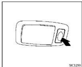
natural_image
Simple line drawing of a device with a cursor pointing to it (no text or symbols)PERSONALLIGHTS
Pushthebuttonasillustratedtoturnthe lightonoroff.

text_image
Diagram of a car air conditioner panel with labeled buttons and status indicatorsINTERIORLIGHTCONTROL SWITCH
① ONswitch
WhentheONswitch ① ispushedin, the maplightsandrearpersonallightswill illuminate. Whentheswitchispushedoff, the lightswillnotilluminate, regardless of the condition.
② DOOROFFswitch
WhentheDOOROFFswitch ② isnot pushed in, the map lights and rear personal lights will illuminate under the following conditions:
-ignitionswitchisswitchedtotheOFF position —remainonforabout15seconds.
- doorsareunlockedbypushingthe UNLOCKbuttononthelIntelligentKey oronetouchunlocksensorwiththe ignitionswitchintheLOCKposition —remainonforabout15seconds.
-anydoorisopenedandthenclosed withtheignitionswitchintheLOCK position —remainonforabout15seconds.
●anydoorisopened —remainonwhilethedoorisopened. Whenthedoorisclosed,thelights gooff.
WhentheDOOROFFswitch ② ispushed in, themapandrearpersonallightswill notilluminateundertheabovecondition. Themapandrearpersonallightscanbe turnedononlywiththeONswitch ①.
Thelightswillalsoturnoffafteraperiod oftimewhenthelightsremainilluminated afterthelnignitionswitchhasbeenpushed totheOFForLOCKpositiontopreventthe batteryfrombecomingdischarged.
When[LampONWhenDoorUnlocks]isset totheOFFposition(seethelnfinitiInTouch
Owner's Manual), the lightswillilluminate underthe following condition:
-anydoorisopenedwiththeignition switchinanyposition —remainonwhilethedoorisopened. Whenthedoorisclosed,thelights gooff.

CAUTION
Donotuseforextendedperiodsoftimewith theenginestopped. Thiscouldresultina dischargedbattery.
VANITYMIRRORLIGHTSTRUNKLIGHT

natural_image
Simple line drawing of a car door handle with a scroll wheel and directional arrows indicating motion (no text or symbols)Thelightonthevanitymirrorwilltumon whenthecoveronthevanitymirroris opened.
Whenthecoverisclosed,thelightwillturn off.
Thelightswillalsoturnoffafteraperiod oftimewhenthelightsremainilluminated topreventthebatteryfrombecoming discharged.
Thelightilluminateswhentetrunklidis opened. Whentetrunklidisclosed, the lightwillturnoff.
Thelightwillalsoturnoffafteraperiodof timewhenthelightremainsilluminated aftertheignitionswitchhasbeenpushed totheOFForLOCKpositiontopreventthe batteryfrombecomingdischarged.

Information Provided by: DEALER
Instrumentsandcontrols2·55
COURTESYLIGHT
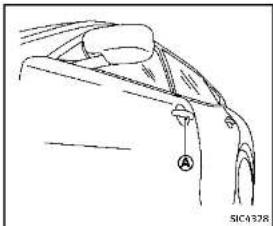
natural_image
Line drawing of a garment collar with a knob labeled 'A' and a small inset detail (no text or symbols)Whenthedoorsareunlockedbypushing theUNLOCKbuttononthelIntelligentKey ortouchingtheonetouchunlocksensor withtheignitionswitchintheLOCK position,thecourtesylight Ⓐ willilluminate.
Toactivateordeactivatethecourteslight, set[LampONWhenDoorUnlocks].Seethe InfinitiInTouchOwner'sManual.
HomeLink® UNIVERSAL TRANSCEIVER(ifso equipped)
TheHomeLink ^® UniversalTransceiverprovidesaconvenientwaytoconsolidatethe functionsofuptothreeindividualhand-heldtransmittersintoonebuilt-indevice. HomeLink ^® UniversalTransceiver:
●WilloperatemostRadioFrequency(RF) devicesuchasgaragedoors,gates, homeandofficelighting,entrydoor locksandsecuritysystems.
- Ispowered by your vehicle's battery. No separate batteries are required. If the vehicle's battery is discharged, is disconnected, HomeLink ^® will retain all programming.
WhentheHomeLink ^® UniversalTransceiverisprogrammed, retaintheoriginal transmitterforfutureprogrammingprocedures (Example: new vehicle purchases). Uponsaleofthevehicle, theprogrammed HomeLink ^® UniversalTransceiverbuttons should be erased for security purposes. For additional information, referto "ProgrammingHomeLink" (P.2-57).
WARNING
- Do not use the HomeLink® Universal Transceiver with any garage door opener that lacks safety stop and reverse
featuresasrequiredbyfederalsafety standards.(Thesestandardsbecame effectiveforopenermodelsmanufacturedafterApril1,1982).Agaragedoor openerwhichcannotdetectanobjectin thepathofaclosinggaragedoorand thenautomaticallystopandreverse, does not meet current federal safety standards.Usingagaragedooropener withoutthesefeaturesincreasesetherisk ofseriousinjuryordeath.
- During the programming procedure your garagedoor security gate will open and close (if the transmitter is within range). Makes sure that people or objects are clear of the garagedoor, gate, etc. that you are programming.
-Yourvehicle'sengineshouldbeturned offwhileprogrammingtheHomeLink UniversalTransceiver.Donotbreathe exhaustgases;theycontaincolorless andodorlesscarbonmonoxide.Carbon monoxideisdangerous.Itcancause unconsciousnessordeath.
PROGRAMMINGHomeLink®
If you have any questions or are having difficulty programming your HomeLink buttons, referto the HomeLink website at: www.homelink.comorcall1-800-355-3515.
NOTE:
Itisalsorecommendedthatanewbattery beplacedinthehand-heldtransmitterof the device being programmed to HomeLink® forquickerprogrammingand accuratetransmissionoftheradio-frequency.
- Position the end of your hand-held transmitter 1-3 in (26-76 mm) away from the Home Link surface, keeping the Home Link indicator light ① in view.
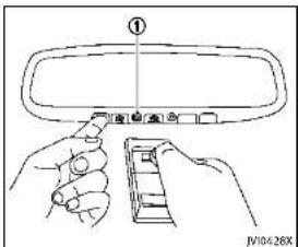
text_image
① JV10428X- Using both hands, simultaneously press and hold the desired HomeLink button and hand held transmitter button. DONOTrelease until the HomeLink indicator light ① flashes slowly and then rapidly. When the indicator light flashes rapidly, both button smaybereleased. (Therapid flashing indicates successful programming.)
NOTE:
Some devices to be programmed may require you to replace Step 2 with the cycling procedure noted in the "Programming HomeLink® for Cardian
customersandgateopeners"(P.2-58).
Instrumentsandcontrols2·57

text_image
① JW10@29X-
Pressandhold the programmed HomeLink ^19 button and observethe indicatorlight.
-
Iftheindicatorlight ① issolid/ continuous,programmingiscompleteandyourdevicesshouldactivatewhentheHomeLink ^® buttonis pressedandreleased.
- Iftheindicatorlight ① blinks rapidlyfortwosecondsandthen turnstoasolid/continuouslight, continuewithSteps4-6forarolling codedevice.Asecondpersonmay makethefollowingstepseasier.Use aladderorotherdevice.Donot
standonyourvehicletoperformthe nextsteps.
- Atthereceverlocatedonthegarage dooropenermotorinthegarage, locate the "learn" or "smart" button (the nameandcolorofthebuttonmayvary bymanufacturerbutilisusually locatednearwherethehangingantennawireisattachedtheunit). If there isdifficultylocatingthebutton, referencethegaragedooropener'smanual.
- Press and releasethe "learn" or "smart" button.
NOTE:
Oncethebuttonispressed,youhave approximately30secondstoinitiate thenextstep.
- Return the vehicle and firmly press and hold the programmed HomeLink button for two seconds and release. Repeat the "press/hold/release" sequence to 3 times complete the programming process. HomeLink should now activate your rolling code equipped device.
- If you have any questions or are having difficulty programming your HomeLink® buttons, refer the
HomeLink® website at: www.homelink.comorcall1-800-355-3515.
PROGRAMMINGHomeLink ^® FOR CANADIANCUSTOMERSANDGATE OPENERS
Canadianradio-frequencylawsrequire transmittersignals to "time-out" (orquit) afterseveralsecondsoftransmission—which may not belongenough for HomeLink® topickupthesignalduring programming.SimilaratothisCanadianlaw,someU.S.geateoperatorsared signedto "time-out" inthesamemanner. IfyouliveinCanadaayouarehaving difficultiesprogrammingagateoperatoror garagedoopenerbyusingthe"ProgramminghomeLink®-procedures,replace"ProgramminghomeLink®-Step2 withthefollowing:
NOTE:
When programmingagaragedooropener, etc., unplugthedeviceduringthe"cy-cling"processtopreventpossibledamage tothegaragedooropenercomponents.
Step2: Using both hands, simultaneously press and hold the desired HomeLink button and the hand-held transmitter
2-58Instrumentsandcontrols
button.Duringprogramming,yourhand-heldtransmittermayautomaticallystop transmitting.Continuetopressandhold thedesiredHomeLink buttonwhileyou pressandre-press("cycle")yourhand-heldtransmittereverytwosecondsuntil thefrequencysignalhasbeenlearned.The HomeLink indicatorlightwillflashslowly andthenrapidlyafterseveralseconds uponsuccessfulprogramming.DONOT releaseuntiltheHomeLink indicatorlight flasheslowlyandthenrapidly.Whenthe indicatorlightflashesrapidly,bothbuttons maybereleased. Therapidflashing indicatesatessuccessfulprogramming.Proceedwith"ProgrammingHomeLink step3tocomplete.
Remembertoplugthedevicebackinwhen programmingiscompleted.
OPERATINGTHEHomeLink ^® UNIVERSALTRANSCEIVER
TheHomeLink ^® UniversalTransceiver,after itisprogrammed,canbeusedtoactivate theprogrammeddevice.Tooperate,simply pressandreleasetheappropriateprogrammedHomeLink ^® UniversalTransceiver button.Theamberindicatorlightwill illuminatewhilethesignalisbeingtransmitted.
Forconvenience, the hand-held transmitter of the device may also be used at any time.
PROGRAMMINGTROUBLESHOOTING
IftheHomeLink ^e doesnotquicklylearn thehand-heldtransmitterinformation:
●replacethehand-heldtransmitterbatterieswithnewbatteries.
- positionthehand-heldtransmitterwith itsbatteryareafacingawayfromthe HomeLink® surface.
- pressandholdboththeHomeLink andhand-heldtransmitterbuttons without interruption.
- positionthehand-heldtransmitter1-3 in (26-76 mm) away from the HomeLink surface. Holdthetransmitterinthatpositionforupto15 seconds. IfHomeLink isnotprogrammedwithinthattime,tryholding thetransmitterinanotherposition-keepingtheindicatorlightinviewatall times.
If you have any questions or are having difficulty programming your HomeLink® buttons, refer to the HomeLink® website at: www.homelink.com or 1-800-355-3515.
CLEARINGTHEPROGRAMMEDINFORMATION
The following procedure clear the programmed information from both buttons. Individual buttonscannotbe cleared. However, individual buttonscanbereprogrammed, see "Reprogrammingasing HomeLink" button"(P.2-59).
Toclearallprogramming
-
Press and hold the two outer HomeLink® buttonsuntiltheindicator lightbeginstoflashinapproximately 10seconds.Donotholdforlongerthan 20seconds.
-
Releasebothbuttons.
HomeLink ^® is now in the programming mode and can be programmed at any time beginning with "ProgrammingHomeLink" -Step1.
REPROGRAMMINGASINGLE
HomeLink® BUTTON
ToreprogramaHomeLink ^® Universal Transceiverbutton,completethefollowing.
-
PressandholdthedesiredHomeLink button.Donotreleasethebutton.
-
The indicator light will begin to flash after 20 seconds. Without releasing the HomeLink ^® button, proceed with "ProgrammingHomeLink ^® -Step1.
Forquestionsorcomments,contact HomeLink® at:www.homelink.comor1-800-355-3515.
TheHomeLink ^® UniversalTransceiverbuttonhasnowbeenreprogrammed. Thenew devicecanbeactivatedbypushingthe HomeLink ^® buttonthatwasjustprogrammed. Thisprocedurewillnotaffect anyotherprogrammedHomeLink ^® buttons.
IFYOURVEHICLEISSTOLEN
If your vehicle is stolen, you should change the codes of any non-rolling coded device that has been programmed into HomeLink ^® . Consult the Owner's Manual of each device or call them manufacturer or retailer of those devices for additional information.
Whenyourvehicleisrecovered,youwill needtoreprogramtheHomeLink ^® UniversalTransceiverwithyournewtransmitterinformation.
FCCNotice:
ForUSA:
ThisdevicecomplieswithPart15ofthe FCCRules.Operationissubjecttothe followingtwoconditions:(1)Thisdevice maynotcauseharmfulinterference,and (2)thisdevicemustacceptanyinterferencereceived,includinginterferencethat maycauseundesiredoperation.
NOTE:
Changesormodificationsnotexpressly approvedbythepartyresponsiblefor compliancecouldvoidtheuser'sauthority tooperatetheequipment.
ForCanada:
This device complies with RSS-210 of Industry Canada. Operation is subject to the following two conditions: (1) this devicemay not cause interference, and (2) this devicemust accept any interference, including interference that may cause undesired operation of the device.
2-60Instrumentsandcontrols

3Pre-drivingchecksandadjustments
Keys....3-2
IntelligentKey....3-2
Valethand-off....3-3
Doors....3-4
Lockingwithmechanicalkey....3-4
Opening and closing windows with
mechanicalkey....3-4
Lockingwithinsidelockknob....3-5
Lockingwithpowerdoorlockswitch....3-5
Automaticdoorlocks....3-5
Childsafetyreardoorlock....3-6
IntelligentKeysystem....3-6
IntelligentKeyoperatingrange....3-8
Doorlocks/unlocksprecaution....3-9
IntelligentKeyoperation....3-9
Batterysaversystem....3-12
Warningsignals....3-12
Troubleshootingguide....3-13
Log-infunction....3-14
Remotekeylessentrysystem....3-14
Howtouseremotekeylessentrysystem.....3-15
Hood 3-18
Trunklid....3-19
Trunklidreleaseswitch....3-19
Trunkopenrequestswitch....3-19
TRUNKbutton 3-20
Trunkreleasepowercancelswitch....3-20
Interiortrunklidrelease....3-21
Fuel-fillerdoor 3-21
Openingthefuel-fillerdoor....3-21
Fuel-fillercap....3-22
Tilt/telescopicsteering....3-24
Manualoperation(ifsoequipped)....3-24
Electricoperation(ifsoequipped)....3-25
Sunvisors....3-25
Mirrors....3-26
Insidemirror....3-26
Outsidemirrors....3-27
Vanitymirror....3-29
Automaticdrivepositioner(ifsoequipped).....3-29
Entry/exitfunction....3-29
Memorystorage....3-30
Systemoperation....3-31

KEYS
Akeynumberplateissuppliedwithyour keys.Recordthekeynumberandkeepitin asaleplace(suchasyourwallet),notin thevehicle.Ifyouloseyourkeys,seen INFINITretailerforduplicatesbyusingthe keynumber.INFINITdoesnotrecordany keynumberssoitisveryimportanttokeep trackofyourkeynumberplate.
Akeynumberisonlynecessarywhenyou havelostallkeysanddonothaveoneto duplicatefrom.Ifyoustillhaveakey,this keycanbeduplicatedbyanINFINITI retailer.
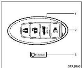
text_image
1 2 3 XXXXX SPA2865- IntelligentKeys(2)
2.Mechanicalkeys(insidetheKeys)(2)
3.Keynumberplate(1)
INTELLIGENTKEY
Yourvehiclecanonlybedrivenwiththe IntelligentKeyswhichareregisteredto yourvehicle'sIntelligentKeysystemcomponentsandINFINITIVehicleImmobilizer Systemcomponents.Asmanyas4IntelligentKeyscanberegisteredandusedwith one vehicle. The new keys must be registered by an INFINITI retailer prior to use with the Intelligent Key system and INFINITI Vehicle Immobilizer System of your vehicle. Since the registration process requireserasingallmemoryinthIntelligentKeycomponentswhenregistering newkeys,besuretotakeallIntelligent KeysthatyouhavetotheINFINITlretailer. ItispossiblethattheIntelligentKey functionsbecomecanceled.Contactan INFINITlretailer.

CAUTION
- BesuretocamytheIntelligentKeywith you when driving. The Intelligent Key is a precisiondevicewithabuilt-intransmitter.Toavoiddamagingit,pleasenote thefollowing.
— The Intelligent Key is water resistant; however, wetting may damage the Intelligent Key. If the Intelligent Key gets wet, immediately wipe until it is completely dry.
— Donotbend, droporstrikeit againstanotherobject.
- Iftheoutsidetemperatureisbelow 14°F (-10°C), the battery of the IntelligentKeymaynotfunction properly.
3-2 Pre-driving checks and adjustments
— DonotplacetheIntelligentKeyfor anextendedperiodinaplacewhere temperaturesexceed140 F(60 °C).
— DonotchangeormodifytheIntelligentKey.
— Donotuseamagnetkeyholder.
— DonotplacetheIntelligentKeynear anelectricappliancesuchasa televisionsetorpersonalcomputer.
— DonotallowtheIntelligentKeyto comeintocontactwithwaterorsalt water, and donotwashitina washingmachine. This could affect the system function.
- If an Intelligent Key is lost stolen, INFINITI recommend serasing the ID code of that Intelligent Key. This will prevent the Intelligent Key from unauthorized usetounlock the vehicle. For information regarding the erasing procedure, contact an INFINIT retailer.

text_image
Technical diagram showing a mechanical component with an inset view of a device labeled 'SPA2033'Mechanicalkey
Toremovethemechanicalkey,releasethe lockknobatthebackofthelntelligentKey. Toinstallthemechanicalkey,firmlyinsert itintothelntelligentKeyuntilthelock knobreturnstothelockposition
Usethemechanicalkeytolockorunlock thedoors, gloveboxandtrunkpass-throughlid, iftheyareequippedwitha keycylinder.
See "Doors" (P.3-4), "Glove box" (P.2-46) and "Trunk pass-through" (P.1-7).

CAUTION
Alwayscarrythemechanicalkeyinstalledin thekey.
VALETHAND-OFF
Whenyouhavetoleaveakeywithavalet, givethemtheIntelligentKeyitselfand keepthemechanicalkeywithyouto protectyourbelongings.
Topreventthegloveboxandthetrunk frombeingopenedduringvalethand-off, followtheproceduresbelow.
-
Pushthetrunkreleasepowercancel switchtotheOFF(cancel)side.
-
Removethemechanicalkeyfromthe IntelligentKey.
-
Lockthegloveboxandthetrunkpass-throughwiththemechanicalkey.
-
HandtheIntelligentKeytothevalet, keepingthemechanicalkeyinyour pocketorbagforinsertionintothe IntelligentKeywhenyouretrieveyour vehicle.
See "Trunk lid" (P.3-19), "Glove box" (P.2-46) and "Trunkpass-through" (P.1-7).
Pre-drivingchecksandadjustments
DOORS

WARNING
●Alwayshavethedoorslockedwhile driving. Alongwiththeuseofseatbelts, thisprovidesgreatersafetyintheevent ofanaccidentbyhelpingtoprevent personsfrombeingthrownfromthe vehicle. Thisalsohelpskeepchildren andothersfromunintentionallyopening thedoors, andwillhelpkeepout intruders.
●Beforeopeninganydoor,alwayslookfor andavoidoncomingtraffic.
- Donotleavechildrenunattendedinside thevehicle. Theycouldunknowingly activateswitchesorcontrols. Unattendedchildrencouldbecomeinvolved inseriousaccidents.
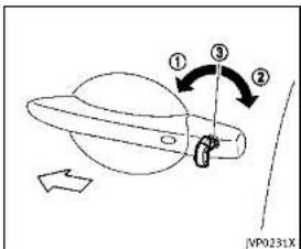
text_image
① ③ ② NP0231XLOCKINGWITHMECHANICALKEY
The powerdoor lock system allows you to lock or unlock all door simultaneously using the mechanical key.
- Turningthedriver'sdoorkeycylinderto thefrontofthevehicle ① willlockall doors.
- Turningthedriver'sdoorkeycylinder oncetotherearofthevehicle ② will unlockthedriver'sdoor. Afterreturning the key to the neutral position ③, turning it to the rear again within 60 seconds will unlock all doors.
- Youcanswitchthelocksystemtothe modethatallowsyoutopenallthe doorswhenthekeyisturnedonce. (SeethelnfinitilnTouchOwner'sManualfordetails.)
OPENINGANDCLOSINGWINDOWS WITHMECHANICALKEY
Thedriver'sdoorkeyoperationalsoallows youtoopenandclosethewindowthatis equippedwiththeautomaticopen/close function.(See"Powerwindows"(P.2-49).)
Toopenthewindow,turnthedriver'sdoor keycylindertotherearofthevehiclefor longerthan1second.Thedoorisunlocked andthewindowkeepsopeningwhile turningthekey.
This function can also be performed by pushing and holding the UNLOCK button on the Intelligent Key. (See "Remote key-lessentry system" (P.3-14).)
Toclosethewindow,turnthedriver'sdoor keycylindertothefrontofthevehiclefor longerthan1second.Thedoorislocked andthewindowkeepsclosingwhileturningthekey.
3-4Pre-drivingchecksandadjustments
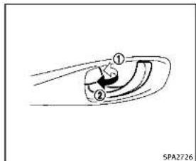
text_image
① ② SPA2726LOCKINGWITHINSIDELOCKKNOB
Tolockthedoorindividually,movethe insidelockknobtothelockposition thenclosethedoor.
Tounlock, movetheinsidelockknobtothe unlockposition ②.
WhenlockingthedoorwithoutanIntelligentKey,besurenottoleavethe IntelligentKeyinsidethevehicle.

text_image
① ② ① ② SPA2727LOCKINGWITHPOWERDOORLOCK SWITCH
Operating the power door lock switch will lock or unlock all the doors. The switches are located on the driver's sand front passenger's door arm rests.
Tolockthedoors, pushthepowerdoor lockswitchtothelockposition ① withthe driver'sorfrontpassenger'sdooropen, thenclosethedoor.
When locking the door this way, be certain not to leave the Intelligent Key inside the vehicle.
To unlock the doors including the fuel-filler
door.pushthepowerdoorlockswitchto theunlockposition ②.
Lockoutprotection
Whenthepowerdoorlockswitchismoved tothelockpositionandanydooropen,all doorswilllockandunlockautomatically. WiththeIntelligentKeyleftinthevehicle andanydooropen,alldoorswillunlock automaticallyandachimewillsoundafter thedoorisclosed.
Thesefunctionshelptopreventthein-telligentKeyfrombeingaccidentally lockedinsidethevehicle.
AUTOMATICDOORLOCKS
- Alldoorslockautomaticallywhenthe vehiclespeedreaches15MPH(24 km/h).
- Alldoorsunlockautomaticallywhenthe ignitionswitchisplacedintheOFF position.
The automatic unlock function can be deactivated or activated. Tode activateur activatethe automatic door unlock system, perform the following procedure:
- PlacetheignitionswitchintheON position.
Pre-drivingchecksandadjustments3-5
INTELLIGENTKEYSYSTEM
- Within 20 second of performing Step 2, push and hold the power door lock switch to the position (UNLOCK) for more than 5 seconds.
- When activated, the hazard indicator will flashtwice. Whendeactivated, the hazard indicator will flashonce.
- Theignitionswitchmustbeplaced in theOFFandONpositionagainbetween eachsettingchange.
When the automatic door unlock system is deactivated, the doors donot unlock when the ignitions switch is placed in the OFF position. Tounlock the doormanually, use the insidelock knoborthepower door lock switch (driver's or front passenger's side). The automatic door unlock function can be changed on the lower display. (See the InfinitIn Touch Owner's Manual.)
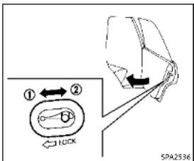
text_image
① ← ② LOCK SPA2536CHILDSAFETYREARDOORLOCK
Thechildsafetyreardoorlockhelps preventdoorsfrombeingopenedaccidentally,especiallywhensmallchildrenarein thevehicle.
Whentheleversareinthelockposition ①, thereardoorscanbeopenedonly fromtheoutside.
Todisengage, movetheleverstothe unlockposition ②.

WARNING
●Radiowavescouldadverselyaffect electricmedicalequipment. Those who useapacemakershouldcontactthe electricmedicalequipmentmanufacturer forthepossibleinfluencesbeforeuse.
- The Intelligent Key transmits radio waves whenthe buttons are pushed. The FAA advises that the radiowaves may affect aircraft navigation and communications systems. Donotoperatethe Intelligent Key while on an airplane. Makes sure the buttons are not operated unintentionally when the unit is stored during a flight.
TheIntelligentKeysystemcanoperateall thedoorsandthetrunklidusingthe remotecontrollerfunction,usingonetouch unlockfunctionorpushingtherequest switchonthevehicelowouttakking the keyoufromapocketorpurse. The operatingenvironmentand/orconditions may affecttheIntelligentKeysystem operation. Besuretoreadthefollowingbeforeusing theIntelligentKeysystem.
3-6 Pre-driving checks and adjustments

CAUTION
- BesuretocarrytheIntelligentKeywith
youwhenoperatingthevehicle.
●NeverleavetheIntelligentKeyinthe
vehiclewhenyouleavetnevenicle.
The Intelligent Key is always communicating with the vehicle as it receives radio waves. The Intelligent Keysystemtransmits weak radiowaves. Environmental conditions may interfere with the operation of the Intelligent Keysystem under the following operating conditions.
- Whenoperatingnearalocationwhere strongradiowavesaretransmitted, suchasaTVtower,powerstationand broadcastingstation.
- Wheninpossessionofwirelessequipment, suchasacellulartelephone, transceiver,andCBradio.
- WhentheIntelligentKeyisincontact withorcoveredbymetallicmaterials.
- Whenanytypeofradiowaveremote controlisusednearby.
- WhentheIntelligentKeyisplacednear anelectricappliancesuchasaperso-
nalcomputer.
-Whenthevehicleisparkedneara
parkingmeter.
Insuchcases, correct the operating condi-
tionsbeforeusingtheIntelligentK
functionbrusetnemechanicalkey.
Although the life of the battery varies depending on the operating conditions, the battery's life is approximately 2 years. If the battery is discharged, replace it with anewone.
SincetheIntelligentKeyiscontinuously receivingradiowaves,ifthekeyisleftnear equipmentwhichtransmitsstrongradio waves,suchassignalsfromaTVand personalcomputer,thebatterylifemay becomeshorter.
For information regarding replacement of battery, see "Intelligent Key battery replacement" (P.8-24).
Asmanyas4IntelligentKeyscanbe registeredandusedwithonevehicle. For informationaboutthepurchaseanduseof additionalIntelligentKeys,contactan INFINITlr etailer.


CAUTION
- DonotallowtheIntelligentKey, which containsselectricalcomponents,tocome intocontactwithwaterorsaltwater.
This could affect the system • Donotdropthe Intelligent Key.
- DonotstriketheIntelligentKeysharply againstanotherobject.
- DonotchangeomodifytheIntelligent Key.
- WettingmaydamagetheIntelligentKey. IftheIntelligentKeygetswet,immediatelywipeuntilitiscompletelydry.
- DonotplacetheIntelligentKeyforan extendedperiodinanareawhere temperaturesexceed140°F(60°C).
- Iftheoutsidetemperatureisbelow14 F (-10 C), the batteryofthelntelligent Keymaynotfunctionproperly.
- DonotattachtheIntelligentKeywitha keyholderthatcontainsamagnet.
- DonotplacethIntelligentKeynear equipmentthatproducesamagnetic field,suchasaTV,audioequipment andpersonalcomputers.
IfanIntelligentKeyislostorstolen, INFINITIrecommendserasingtheIDcode of that IntelligentKeyfromthevehicle. This maypreventtheunauthorizeduseofthe IntelligentKeytooperatethevehicle. For informationregardingtheerasingprocedure, contactanINFINITIretailer.
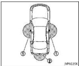
text_image
① ② JP0225Xcm)fromeachonetouchunlocksensor/ doorhandlerequestswitch ① andtrunk openrequestswitch ②. If the Intelligent Key is too close to the door glass, handleorrearbumper, the one touchunlocksensorandrequestswitches maynotfunction. WhentheIntelligentKeyiswithinthe operatingrange, itispossibleforanyone whodoesnotcarrytheIntelligentKeyto usethe onetouchunlock sensororrequest switchestolockorunlockthedoorsand openthetrunklid.
WhentheIntelligentKeybatteryisdis- chargedorstrongradiowavesarepresent neartheoperatinglocation,theIntelligent Key system's operating range becomes narrower, and the Intelligent Key may not function properly.
The operating range is within 31.50 in (80
3-8Pre-drivingchecksandadjustments
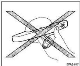
natural_image
Illustration of a hand holding a tool with intersecting blades, no text or symbols presentDOORLOCKS/UNLOCKSPRECAUTION
- Donotpushthedoorhandlerequest switchwiththeIntelligentKeyheldin yourhandasillustrated. The close distancetothedoorhandlewillcause the Intelligent Keysystemt have difficulty recognizing that the Intelligent Keyisoutsidethevehicle.
■Within2secondsafterthedoorare lockedusingthedoorhandlerequest switch,makesurethatthedoorshave beensecurelylockedbyoperatingthe doorhandles.Ifyoukeepholdingthe doorhandleformorethan2seconds
afterlockingthedoorsusingthedoor handlerequestswitch, thedoorwillbe unlocked.
- TopreventtheIntelligentKeyfrom beingleftinsidethevehicleorthetrunk,makesureyoucarrythekeywith youandthenlockthedoorsorthe trunk.
- TheIntelligentKeysystem(opening/closingdoorswiththedoorhandlerequestswitchoronetouchunlock sensor)canbesettoremaininactive. (SeethelInfinitiInTouchOwner'sManual.)
- Thedoorcannotbeunlockedusingone touchunlockoperationalterlockingthe doorwithin2seconds.Tounlockthe door,releasethedorhandleonceand holditagain.
- Donotholdandpullthedoorhandle quickly. Thedoorwillbeunlockedbut willnotopen. Releasethedorhandle onceandpullitagaintoopenthedoor.
- If you pull the door handle with your gloved hand, the one touch unlock operation may not function.


text_image
JVP0232XYoucanlockorunlockthedoorswithout takingthekeyoutfromyourpocketorbag.
Pre-drivingchecksandadjustments3-9

text_image
JVP0233X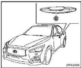
natural_image
Line drawing of a car with a component labeled B, no text or symbols presentWhenyoucarrytheIntelligentKeywith
3-10 Pre-driving checks and adjustments
you,youcanlockaldoorsbypushingthe doorhandlerequestswitch ④ (driver'sor frontpassenger's)withintherangeof operation.
Youcanalsounlockthecorresponding doorbytouchingtheonetouchunlock sensor (driver'sorfrontpassenger's) withintherangeofoperation,andcan unlocktheotherdoorsusingthedoor handlerequestswitch (A).
Whenyoulockorunlockthedoorsorthe trunklid,thehazardindicatorwillflash andthehorn(ortheoutsidechime)will soundasaconfirmation.Fordetails,see "Settinghazardindicatorandhornmode" (P.3-16).
CAUTION
- Afterlockingthedoorsusingtherequest switch,makesurethatthedoorshave beensecurelylockedbyoperatingthe doorhandles.
- Whenlockingthedoorsusingthe request switch, make sure to have the Intelligent Key in your possession before operating the request switch to prevent the Intelligent Key from being left in the
vehicle.
- Therequestswitchisoperationalonly whentheIntelligentKeyhasbeen detectedbytheIntelligentKeysystem.
Lockoutprotection
TopreventtheIntelligentKeyfrombeing accidentallylockedinthevehicle,lockout protectionisequippedwiththeIntelligent Keysystem.
Whenthedriver'ssidedoorisopen,the doorsare locked,andthen theIntelligent Keyisputinsidethevehicleandallthe doorsareclosed;thelockwillautomaticallyunlockandthedoorbuzzersounds.
NOTE:
The doors may not lock when the IntelligentKeyisinthesamehandthatis operatingtherequestswitchtolockthe door.PuttheIntelligentKeyinapurse, pocketoryourotherhand.
CAUTION
Thelockoutprotectionmaynotfunction underthefollowingconditions:
- When the Intelligent Key is placed on top of the instrument panel.
- When the Intelligent Key is placed inside the gloveboxorastoragebin.
- When the Intelligent Key is placed inside the door pockets.
- WhentheIntelligentKeyisplacedinside ornearmetallicmaterials.
Lockingdoorsandfuel-fillerdoor
- PushtheignitionswitchtotheOFF positionandmakesureyoucarrythe IntelligentKeywithyou.*1
2.Closeallthedoors.*2
3.Pushthedoorhandlerequestswitch (driver'sorfrontpassenger's) ① while carryingtheIntelligentKeywithyou.*3
-
Allthedoorsandfuel-fillerdoorwill lock.
-
The hazard indicator flashestwice and the outside chimesoundstwice.
*1: DoorswilllockwiththeIntelligentKey whiletheignitionswitchisintheACC orONposition.
*2: DoorswillnotlockwiththeIntelligent Keywhileanydoorisopen.
*3: Doorswillnotlockbypushingthe doorhandlerequestswitchwiththe IntelligentKeyinsidethevehicle. However,whenanIntelligentKeyis insidethevehicle,doorscanbe lockedwithanotherregisteredIntelligentKey.
Unlockingdoorsandfuel-fillerdoor
-
Holdtheoutsidedoorhandle(driver's orfrontpassenger's)whilecarryingthe IntelligentKeywithyou.
-
The hazard indicator flashes once and the outside chimes sounds once. The corresponding door will unlock.
3.Pushthedoorhandlerequestswitch within1minute.
- The hazard indicator flashes once and the outside chimes sounds once again. All the doors and fuel-fill erdoor will unlock.
Alldoorsandthefuel-fillerdoorwillbe lockedautomaticallyunlessoneofthe followingoperationsisperformedwithin1 minuteafterpushingtherequestswitchor touch unlock operation while the doors are locked.
- Opening any door
- Pushingtheignitionswitch Duringthis1-minutetimeperiod,ifthe UNLOCK buttonontheIntelligentKey ispushed,alldoorswillbelockedautomaticallyafteranother1minute.
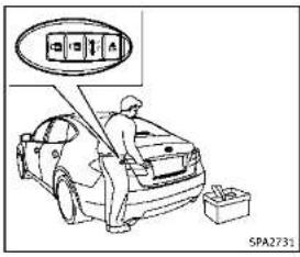
text_image
SPA2731
natural_image
Line drawing of a car exterior view with a close-up inset showing the front and rear components (no text or symbols)Openingtrunklid
-
Pushthetrunkopenrequestswitch formorethan1second.
-
Thetrunkwillunlatch. An outside chimewillsoundfourtimes.
-
Raisethetrunklidtoopenthetrunk.
Lockoutprotection:
TopreventtheIntelligentKeyfrombeing accidentallylockedinthetrunk,lockout protectionisequippedwiththeIntelligent Keysystem.
Whenthetrunklidisclosedwiththe IntelligentKeyinsidethetrunk,theoutside chimewillsoundandthetrunkwillopen.
BATTERYSAVERSYSTEM
When all the following conditions are met for a period of time, the batteriesaver system will cutoff the powers supply to prevent battery discharge.
•TheignitionswitchisintheACC position,and
- Alldoorsareclosed, and
- The shift lever is in the P (Park) position.
WARNINGSIGNALS
Tohelppreventthevehiclefrommoving unexpectedlybyerroneousoperationof theIntelligentKeylistedonthefollowing chartortohelpreventthevehiclefrom beingstolen,chimeorbeepsoundsinside andoutsidethevehicelandawarning displaysinthevehicelinformationdisplay. Whenachimeorbeepsoundsorthe warningdisplays,besuretocheckthe vehicleandIntelligentKey. See“Troubleshootingguide”(P.3-13)and “Vehicleinformationdisplay”(P.2-20).
3-12 Pre-driving checks and adjustments

TROUBLESHOOTINGGUIDE
| SymptomPossiblecauseActiontotake | |||
| Whenpushingtheignitionswitchtastoptheengine | TheSHIFTPwarningappearsonthedisplayandtheinsidewarningchimesoundscontinuously. | TheshiftleverisnotintheP(Park)position. | ShifttheshiftlevertotheP(Park)position. |
| WhenshiftingtheshiflevertothoP(Park)position. | Theinsidewarningchimesoundscontinuously. | TheignitionswitchisintheACConOnposition. | PushtheignitionswitchthatheOFFposition. |
| Whenapeningthedriver'sdoortogeloutofthevehicle | Theinsidewarningchimesoundscontinuously. | TheignitionswitchisintheACCposition. | PushtheignitionswitchthatheOFFposition. |
| Whenclosingthedoraftergettinggoutofthevehicle | TheNOKEYwarningappearsonthedisplay,theoutsidechimesounds3timesandtheinsidewarningchimesoundsforafewseconds. | TheignitionswitchisintheACConOnposition. | PushtheignitionswitchthatheOFFposition. |
| TheSHIFTPwarningappearsonthedisplayandtheoutsidechimesoundscontinuously. | TheignitionswitchisintheACConOFFpositionandthehsiftleverisnotintheP(Park)position. | MowetheshiflevertotheP(Park)positionandpushtheignitionswitchthatheOFFposition. | |
| WhenclosingthedorwiththeinsidelocknobtumedtoLOCK | Theoutsiclechimesoundsforafewsecondsandallthedoorsunlock. | TheIntelligentKeyisinsidethevehiclertrunk. | CarrytheIntelligentKeywithyou. |
| WhenpushingtherquesswitchorLOCKbuttonontheintelligentKeytolockthedoor | Theoutsiclechimesoundsforafewseconds. | TheIntelligentKeyisinsidethevehiclertrunk. | CarrytheIntelligentKeywithyou. |
| Adovilsnetclosedseacurely.Closethedoorscurely. | |||
| Whenclosingthetrunklid | Theoutsiclechimesoundsforapproximately10secondsandthermunklidopens. | TheIntelligentKeyisinsidethertrunk. | CarrytheIntelligentKeywithyou. |

Pre-drivingchecksandadjustments3-13
REMOTEKEYLESSENTRYSYSTEM
LOG-INFUNCTION
Aftersettinguptheuserinformation,the systemwillautomaticallyrecognizethe useruponturningonthevehicle.
Therewillbeapersonalizedwelcome greetingandscreenprompttolog-in. Thisfeatureallows4driverstousetheir ownregistration,drivemode,drivingposition,airconditioner,andautosettingsand memorizesthesecustomsettings.
Theolog-inusercanbechangedonthe welcomegreetingscreenortheUserList screen.Formoredetails,seethelnfiniti InTouchOwner'sManual.
Theolog-infunctionislinkedtothefollowingitems:
●Meter
■Audio
●Navigation system display (if so equipped)
- Navigationsettings(ifsoequipped) - Airconditioner
●Automatic drive positioner(ifso equipped)
■Engine-Transmission
3-14Pre-drivingchecksandadjustments
- Steering(ifsoequipped)
●Activetracecontrolsystem
- Driverassistance(ifsoequipped)

WARNING
The Intelligent Key transmits radiowaves when the buttons are pushed. The FAA advises that the radiowaves may affect aircraft navigation and communications systems. Donot operate the Intelligent Key while on an airplane. Makes sure the buttons are not operated by unintentionally when the unit is stored during a flight.
Itispossiblelotolock/unlockalldoorsand fuel-fillero door, openthetrunklid, activate thepanicalarmandopenthewindowsby pushingthebuttonsonthelIntelligentKey fromoutsidethevehicle.
Beforelockingthedoors, makesurethe IntelligentKeyisnotleftinthevehicle.
Theremotekeylessentryfunctioncan operateatadistanceofapproximately33 ft(10m)fromthevehicle.(Theeffective distancedependsupontheconditions aroundthevehicle.)
Asmanyas4IntelligentKeyscanbeused withonevehicle.Forinformationconcerningthepurchaseanduseofadditional IntelligentKeys,contactanINFINITretailer.
ThebuttonsontheIntelligentKeywillnot operatewhen:
- thedistancebetweentheIntelligentKey andthevehicleisover33ft(10m).
•theIntelligentKeybatteryisdischarged.
Afterlockingwiththeremotekeylessentry function, pullthedoorhandletomakesure thedoorsaresecurelylocked.
TheLOCK/UNLOCKoperatingrangevaries dependingontheenvironment.Tosecurely operatethelockandunlockbuttons, approachthevehicletoabout3ft(1m) fromthedoor.

text_image
① ② ③ ④ SPA2100- LOCKbutton
2.UNLOCKbutton
3.TRUNKbutton
4.PANICbutton


HOWTOUSEREMOTEKEYLESS ENTRYSYSTEM
Whenyoulockorunlockthedoorsorthe trunklid,thehazardindicatorwillflash andthehorn(ortheoutsidechime)will soundasaconfirmation.Fordetails,see "Setting hazard indicator and horn mode" (P.3-16).

Lockingdoorsandfuel-fillerdoor
- PushtheignitionswitchtotheOFF positionandmakesureyoucarrythe IntelligentKeywithyou.*1
2.Closeallthedoors.
- Pushthel OCK
button ① onthe
IntelligentKey.
-
Allthedoorsandfuel-fillerdoorwill lock.
-
The hazard indicator flashestwice and the homchirpsonce.
*1: DoorswilllockwiththeIntelligentKey whiletheignitionswitchisintheACC orONposition.
Unlockingdoorsandfuel-fillerdoor
- PushtheUNLOCKbutton
② onthe
IntelligentKeyonce.
- The hazard indicator flashes once. The driver's door will unlock.
3.PushtheUNLOCK 🔒 button ② onthe IntelligentKeyagainwithin1minute.
- The hazard indicator flashes once again. All the doors and the fuel filler door will unlock.
Alldoorsandthefuel-fillerdoorwillbe lockedautomaticallyunlessoneofthe
followingoperationsisperformedwithin1 minuteafterpushingtheUNLOCK buttononthelIntelligentKeywhilethe doorsarelocked.lfduringthis1-minute timeperiod,theUNLOCK buttonon theIntelligentKeyispushed,alldoorswill belockedautomaticallyafteranother1 minute.
- Openinganydoor
- Pushingtheignitionswitch
Openingwindows(ifsoequipped)
TheUNLOCKbutton ② operationalso allowsyoutoopenthewindowthatis equippedwiththeautomaticopen/close function.(See“Powerwindows”(P.2-49).)
To open the window, push the door UNLOCK 🔒 ② buttononthelIntelligent Keyforabout3secondsafterthedooris unlocked.
Tostopopening, releasetheUNLOCK button ②.
Ifthewindowopenoperationisstoppedin mid-operationwhilepushingtheUNLOCK button ② ,releaseandpushthe UNLOCK button ② againuntilthe windowopenscompletely.
Windowcannotbeclosedusingthein-
telligentKey.
The door window can also be operated by turning the mechanical key in a door lock. (See "Doors" (P.3-4).)
Openingmoonroof(ifsoequipped) Themoonroofcanbeopenedbypushing theUNLOCK button ② ontheintell gentKey.Thisfunctionwillnotoperate whilethemoonrooftimerisactivatedor whenthewindowsneedtobeinitialized.
Toopenthemoonroof, pushtheUNLOCK button ② ontheIntelligentKeyfor about3secondsafterthedoorisunlocked. Tostopopening, releasetheUNLOCK button ②.
Openingtrunklid
-
PushtheTRUNK button ③ onthe IntelligentKeyformorethan1second.
-
Thetrunkwillunlatch.
-
Raisethetrunklidtoopenthetrunk.
Usingpanicalarm
If you are near your vehicle and feel threatened, you may activate the alarm to callatten tion as follows:
- Push the PANIC ➞ button ④ onthe
keyformorethan1second.
-
Thetheftwamingalarmandheadlights willstayonfor25seconds.
-
Thepanicalarmstopswhen:
- Ithasrunfor25seconds,or - AnyofthebuttonsontheIntelligent Keyarepushed.(Note: PANIC button ④ orTRUNK ➕ button ⑤ shouldbepushedformorethan1 second.)
Settinghazardindicatorandhorn mode
This vehicle is a set in hazard indicator and horn mode when you first receive the vehicle.
Inhazardindicatorandhommode,when theLOCK button ① ispushed,the hazardindicatorflashestwiceandthehorn chirpsonce.WhentheUNLOCK button ② ispushed,thehazardindicatorflashes
Ifhornsarenotnecessary, thesystemcan beswitched to the hazard indicator mode. Inhazardindicator mode, when the LOCK button ① is pushed, the hazard indicator flashest twice. When the UNLOCK button ② is pushed, neither the
3-16Pre-drivingchecksandadjustments
hazardindicatornorthehornoperates.Hazardindicatorandhornmode:
| DOORLOCKDOORU | LOCKTRUNKUNLOCK | ||
| IntelligentKeysystem(Usingdoorhandlerunkrequestswitch) | HAZARD-twiceOUTSIDECHIME-twice | HAZARD-onceOUTSIDECHIME-once | HAZARD-noneOUTSIDECHIME-4times |
| Remotekeylessentrysystem(Using 🔒按钮) | HAZARD-twiceHORN-once | HAZARD-onceHORN-none | HAZARD-noneHORN-none |
Hazardindicatormode:
| DOORLOCKDOORUNLOCKTRUNKUNLOCK | |||
| IntelligentKeysystem(Usingdoorhandletrunkrequestswitch) | HAZARD-twiceOUTSIDECHIME-none | HAZARD-noneOUTSIDECHIME-none | HAZARD-noneOUTSIDECHIME-4times |
| Remetekeylessentrysystem(Using 🔒 .opullarare) | HAZARD-twiceHORN-none | HAZARD-onceHORN-none | HAZARD-noneHORN-none |

Pre-drivingchecksandadjustments3·17
HOOD
Switchingprocedure:
Toswitchthehazardindicatorandhorn
(chime)operation,pushtheLOCK
andUNLOCK 🔒 ② buttonsontheln-
telligentKeysimultaneouslyformorethan
2seconds.
- Whenthehazardindicatormodeisset,
thehazardindicatorflashes3times.
- When the hazard indicator and horn
modeisset,thehazardindicator

flowchart
graph TD
    A["Hazard Indicator and Horn Mode"] --> B["Push (1) for more than 2 sec."]
    B --> C["Hazard - 3 times"]
    C --> D["Push (2) for more than 2 sec."]
    D --> E["Hazard Indicator Mode"]
    style A fill:#f9f,stroke:#333
    style E fill:#f9f,stroke:#333
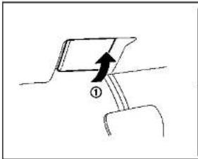
natural_image
Simple line drawing of a mechanical component with an arrow indicating direction (no text or symbols)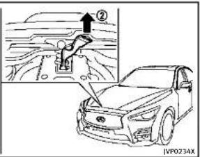
text_image
Diagram showing car safety lever mechanism with labeled parts and a magnified view of the lever mechanism.1.Pullthehoodlockreleasehandle
locatedbelowtheinstrumentpanel;
thehoodwillthenspringupslightly.
2.Pullthelever ② upatthefrontofthe
hoodwithyourfingertipsandraisethe
hoo
- When closing the hood, slowly close
thehoodowntolatchboththeright
andleftlocks.Pushthehooddownto
lockthehoodsecurelyintoplace.
①

WARNING
●Makesurethehoodiscompletelyclosed
andlatchedbeforedriving.Failuretodo
socouldcausethehoodtoflyopenand
resultinanaccident.
- If you esteamorsmokecoming from
theenginecompartment.toavoidinjury
donotopenthehood.
3-18 Pre-driving checks and adjustments

- Donotdrivewiththetrunklidopen. This couldallowdangerousexhaustgasesto bedrawnintothevehicle.See"Exhaust gas(carbonmonoxide)("P.5-3)ofthis manual.
- Closelysupervisechildrenwhentheyare aroundcarstopreventthemfromplayingandbecominglockedinthetrunk wheretheycouldbeseriouslyinjured. Keepthecarlocked,withthetrunk closed,whennotinuse,andprevent children'saccesstointelligentKeys.

text_image
Diagram showing car seatbelt switch with a magnified view of the seatbelt and a vehicle icon, labeled (A) and (B)TRUNKLIDRELEASESWITCH
Thetrunklidreleaseswitch ① islocated ontheinstrumentpanel.
Toopenthetrunklid, pushtherelease switch. Toclose, pushthetrunkliddown.

DEALER
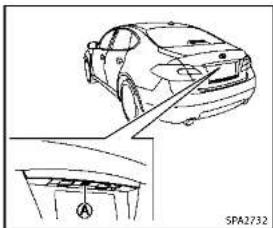
natural_image
Line drawing of a car showing front and side views with no text or symbolsTRUNKOPENREQUESTSWITCH
Thetrunklidcanbeopenedbypushingthe trunkopenrequestswitch A whenthe IntelligentKeyiswithintheoperating rangeofthetrunklock/unlockfunction regardlessoftheinsidelockknobposition. Thetrunklidcanbeopenedbypushingthe trunkopenrequestswitch A evenifthe IntelligentKeyisnotwithintheoperating rangeofthetrunklock/unlockfunction, whenaldoorsareunlockedbythepower doorlocksystem,andtheautomatic unlockfunction.
(See"IntelligentKeysystem"(P.3-6).)
Pre-drivingchecksandadjustments
TRUNKBUTTON
The trunklidcanbeopenedbypushingthe TRUNK ➕ buttononthelIntelligentKeyfor morethan1second.
Thetrunklidcanbeopenedbypushingthe trunkopenrequestswitch evenifthe IntelligentKeyisnotwithintheoperating rangeofthetrunklock/unlockfunction, whenalldoorsareunlockedbythepower doorlocksystem,andtheautomatic unlockfunction.
(See"Remotekeylessentrysystem"(P.3-14).)
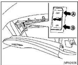
text_image
Diagram of car interior showing valve placement and control panel with labeled parts A and BvehicleandtheIntelligentKeywiththe valetandkeepthemechanicalkeywith you.
(See"Keys"(P.3-2).)
Toconnectthepowertothetrunklid, push theswitchtotheON ⑧ position.
TRUNKRELEASEPOWERCANCEL SWITCH
Whentheswitchlocatedinsidetheglove boxisintheOFFposition Ⓐ,thepowerto thetrunklidwillbecanceledandthetrunk lidcannotbeopenedbythetrunklid releaseswitch,thetrunkopenrequest switchortheTRUNKbuttononthe IntelligentKey.
When you have to leave the vehicle with a valet and want to keep your belongings safe in the glove box and the trunk, push this switch to OFF and lock the glove box with the mechanical key. Then leave the
3-20Pre-drivingchecksandadjustments
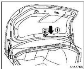
text_image
① SPA2768INTERIORTRUNKLIDRELEASE

WARNING
Closelysupervisechildrenwhentheyare aroundcarstopreventthemfromplaying andbecominglockedinthetrunkwhere theycouldbeseriouslyinjured.Keepthecar locked,withthetrunklidsecurelylatched, whennotinuse,andpreventchildren's accesstoIntelligentKeys.
Theinteriortrunklidreleasemechanism allowsopeningofthetrunklidintheevent
thatpeoplebecomelockedinsidethetrunk orintheeventofthelossofelectrical powersuchasadischargedbattery.
Releasinginsidethetrunk
Toopenthetrunklidfromtheinside,pull thereleasehandle ① untilthelock releasesandpushuponthetrunklid. Thereleaseleverismadeofamaterialthat glowsinthedarkafterabriefexposure to ambientlight.
The handle is located on the back of the trunklidas illustrated.
Releasingfromtherearseat
Youcanaccessthereleasehandlethrough thetrunkpass-through(rearseatarmrest). (See"Armrest"(P.1-7).)
Toopenthetrunklidfromtherearseat, pullthereleasehandletowardsfrontof vehicleuntilthelockreleases.
If you cannot reach the lease handle, contact an INFINIT retailer.

FUEL-FILLERDOOR
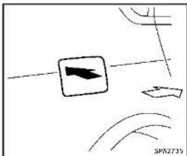
natural_image
Simple line drawing with a directional arrow and curved lines, no text or symbols presentOPENINGTHEFUEL-FILLERDOOR
Toopenthefuel-fillerdoor, unlock the fuel-fillerdoor by using one of the following operations, then push the upper left side of the door.
- Touchtheonetouchunlocksensoron oneofthefrontdoorhandlesandthen pushthedoorhandlerequestswitch whilecarryingtheIntelligentKey.
- PushtheUNLOCKbuttononthelIntelligentKeytwice.
- Insertthemechanicalkeyintothedoor lockcylinderandturnittotherearof thevehicletwice.
Pre-drivingchecksandadjustments3-21
- Pushthepowerdoorlockswitchtothe UNLOCKposition.
Tolock, closethefuel-fillerdoorsecurely andlockalldoorsbyoperatingthedoor handlerequestswitch, theLOCKbuttonon theIntelligentKey, themechanicalkeyor thepowerdoorlockswitch.
FUEL-FILLERCAP

WARNING
•Gasolineisextremelyflammable and highlyexplosiveundercertainconditions.Youcouldbeburnedorseriously injuredlfitismisusedormishandled. Alwaysstopengineanddonotsmokeor allowopenflamesorsparksnearthe vehiclewhenrefueling.
- Donotattempttotopoffthefueltank afterthefuelpumpnozzleshutsoff automatically. Continuedrefuelingmay causefueloverflow, resultinginfuel sprayandpossiblyafire.
•Useonlyanoriginalequipmenttype fuel-fillercapasareplacement.ithasa built-insafetyvalveneededforproper operationofthefuelsystemandemissioncontrolsystem.AnIncorrectcapcan
resultinaseriousmalfunctionand possibleinjury.Itcouldalsocausethe MalfunctionIndicatorLight(MIL)to comeon.
■Neverpourfuelintothethrottlebodyto attempttostartyourvehicle.
■Donotfillaportablefuelcontainerin thevehicleortrailer.Staticelectricity cancauseanexplosionofflammable liquid,vapororgasinanyvehicleor trailer.Toreducetheriskofserious injuryordeathwhenfillingportablefuel containers:
— Alwaysplacethecontaineronthe groundwhenfilling.
— Donotuseelectronicdeviceswhen filling.
— Keepthepumpnozzleincontact withthecontainerwhileyouare fillingit.
— Useonlyapprovedportablefuel containersforflammableliquid.

CAUTION
- lffuelisspilledonthevehiclebody, flushitawaywithwatertoavoidpaint damage.
- Insertthecapstraightintothefuel-filler tube, thentightenthefuel-fillercapuntil asingleclickisheard. Failuretotighten thefuel-fillercappropormycausetheo - MalfunctionIndicatorLight(MIL) to illuminate.Ifthe - lightilluminates becausethefuel-fillercapsilooseor missing,lightenorinstallthecapand continuedotrivethevehicle.The lightshouldturnoffafterafewdriving trips.Ifthe - lightdoesnotturnoff afterafewdrivingtrips,havethevehicle inspectedbyanINFINITretailer.
●TheLooseFuelCapwarningwillappear ifthefuel-fillercapisnotproperly tightened.Itmaytakeafewdriving tripsforthewarningtobdisplayed. Failuretortightentheufuel-fillercap properlyaftertheLooseFuelCapwarmingappearsmaycausethe MalfunctionIndicatorLight(MIL)to illuminate.

DEALER
3-22 Pre-driving checks and adjustments
- For additional information, see "Mal-functionIndicatorLight(MIL)"(P.2-18).

text_image
① NP0204XToremovethefuel-fillercap:
- Turnthefuel-fillercapcounterclockwise toremove.
- Putthefuel-fillercaponthecapholder ① whilerefueling.
Toinstallthefuel-fillercap: - Insert the fuel-fillercap straight into the fuel-fillertube.
- Turnthefuel-fillercapclockwiseuntila singleclickisheard.

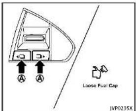
text_image
A A Loose Fuel Gap JVP0235XLoosefuelcapwarning
The Loose Fuel Cap warning appears in the vehicle information display when the fuel fillercapis not tightened correctly after the vehicle has been refueled. It may take a few driving trips forth warning to be displayed.
Toturnoffthewarning,performthe following:
1. Remove and install the fuel-fillercap as soon as possible. (See "Fuel-fillercap" (P.3-22).)
2. Tightenthefuel-fillercapuntilasingingle clickisheard.
Pre-drivingchecksandadjustments3-23
TILT/TELESCOPICSTEERING
- Push theors with □▶ on the steering wheel for longer than 1 second to turn off the Loose Fuel Cap warning after tightening the fuel-fillercap.
WARNING
- Donotadjustthesteeringwheelwhile driving. You could close control of your vehicle and cause an accident.
- Donoladjusttheesteeringwheelany closertoyouthanisnecessaryfor propersteeringoperationandcomfort. Thedriver'salbaginflateswithgreat force.Ilyouareunrestrained, leaning forward, sittingsidewaysorout of positioninawayway,youareatgreater riskofinjuryordeathinacrash.You mayalsoreceiveseriouslyfatalinjures fromtheairbagifyouareupagainstit wheninflates.Awayssitbackagainst theseatbackandasfarawayspractical fromthestheeringwheel.Alwaysusethe seatbelts.

text_image
① SPA733283-24Pre-drivingchecksandadjustments

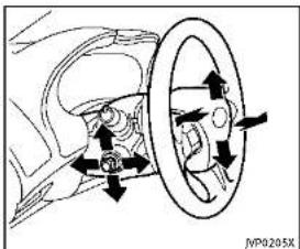
text_image
Diagram showing car wheel and head assembly with directional arrows indicating motion or movementEntry/Exitfunctionoperation:
Theautomaticdrivepositionersystemwill makethesteeringwheelmoveupautomaticallywhenthedriver'sdoorisopened withtheignitionswitchintheLOCK position.Thisletsthedrivergetintoand outoftheseatmoreeasily.
Formoreinformation,see"Automaticdrive positioner"(P.3-29).
SUNVISORS

flowchart
graph TD
    A["Step ①: Body opening"] --> B["Step ②: Rear lock"]
    B --> C["Step ③: Rear lock"]
- Toblockglarefromthefront, swing downthemainsunvisor ①.

Pre-drivingchecksandadjustments3-25
MIRRORS
- Toblockglarefromtheside, remove themainsunvisorfromthecenter mountandswingthevisortotheside ②.
3.Slidethesunvisor needed. ③ inoroutas
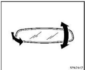
natural_image
Simple line drawing of a curved object with arrows indicating direction (no text or symbols)INSIDEMIRROR
Adjusttheheightandtheangleofthe insidemirrortothedesiredposition.
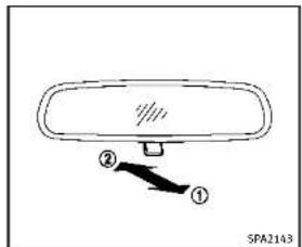
text_image
② ① SPA2143Manualanti-glaretype
Thenightposition ① willreduceglare fromtheheadlightsofvehiclesbehindyou atnight.
Usethedayposition ② whendrivingin daylighthours.

WARNING
Usethenightpositiononlywhennecessary, becauseitreducesrearviewclarity.

3-26Pre-drivingchecksandadjustments

text_image
E A E B SPA24.22ATypeA
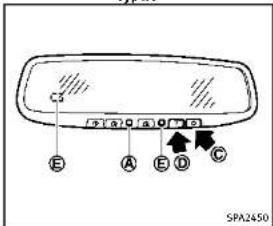
text_image
C3 E A B C SPA2450TypeB
Automaticanti-glaretype
The insidemirroris designed so that it automatically changes reflection according to the intensity of the headlight so the following vehicle.
The anti-glaresystem will be automatically turned on when the ignition switch is pushed to the ON position.
The anti-glaresystemalsooperatesforthe outsidemirrors(ifsoequipped).
Whentheanti-glaresystemisturnedon, theindicatorlight Ⓐ willilluminateand excessiveglarefromtheheadlightsofthe vehiclebehindyouwillbereduced.
TypeA:Pushthe switch tomakethe insidemirroroperatenormallyandthe indicatorlightwillturnoff.Pushthe switchagaintoturnthesystemon.
TypeB:Pushthe“○”switch © tomake theinsidemirroroperatenormally.The indicatorlightwillturnoff.Pushthe“I” switch Ⓑ toturnthesystemon.
Donotallowanyobjecttocoverthe sensors Ⓔ or apply glass cleaner on them. Doing so will reduce the sensitivity of the sensor, resulting in improper operation.
Forthecompass(ifsoequipped)operation,see"Compass"(P.2-9). FortheHomeLink UniversalTransceiver(if soequipped)operation,see"HomeLink UniversalTransceiver"(P.2-56).
OUTSIDEMIRRORS

WARNING
Objectsviewedintheoutsidemirroronthe passengersidearecloserthantheyappear. Becarefulwhenmovingtotheright. Using onlythismirrorcouldcauseanaccident. Usetheinsidemirrororglanceoveryour shouldertopropertyjudgedistance to otherobjects.
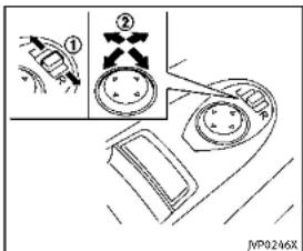
text_image
Diagram showing a mechanical or electrical component with labeled parts and directional arrows, including a zoomed-in section view.Adjustingoutsidemirrors
The outside mirror control switch is located on the driver's armrest.
The outside mirror will operate only when the ignition switch is in the ACCorON position.
Movetheswitch ① rightorlefttoselect therightorleftsidemirror, thenadjust usingthecontrolswitch ②.
Defrostingoutsidemirrors
The outside mirror will be heated when therear window defrosters switch is operated.

natural_image
Diagram of a hand pressing down on a surface with an arrow indicating motion (no text or symbols)Foldableoutsidemirrors
Foldtheoutsidemirrorbypushingit towardtherearofthevehicle.
Reversetilt-downfeature(ifso equipped)
Whenbackingupthevehicle,therightand leftoutsidemirrorswillturndownward automaticallytoprovidebetterrearvisibility.
- Push the ignition switch to the ON position.
-
Move the shift lever to the R (Reverse) position.
-
Selecttherightorleftsidemirrorby operatingtheoutsidemirrorcontrol switch.
- The outside mirror surface moves downward.
Whenoneofthefollowingconditionshas occurred, theoutsidemirrorsurfacewill returntoitsoriginalposition.
●Theshiftleverismovedtoanyposition otherthanR(Reverse).
●Theoutsidemirrorcontrolswitchisset tothecenterposition.
●TheignitionswitchispushedtotheOFF position.
Automaticanti-glare(ifso equipped)
Theoutsiderearviewmirrorsaredesigned sothattheyautomaticallychangereflectionaccordingtotheintensityofthe headlightsofthevehiclefollowingyou.
Theanti-glaresystemwillbeautomatically turnedonwhenyoupushtheignition switchtothe"ON"position.
3-28Pre-drivingchecksandadjustments

natural_image
Simple line drawing of a car rearview handle with a curved arrow indicating direction (no text or symbols)VANITYMIRROR
Tousethefrontvanitymirror,pulldown thesunvisorandpullupthecover.
AUTOMATICDRIVEPOSITIONER(ifso equipped)
The automatic drive positionersystem has two features:
-Entry/exitfunction
■Memorystorage
ENTRY/EXITFUNCTION
This system is designed so that the driver's seat and steering column will automatically move when the shift lever is in the P (Park) position. This allows the driver to get into and out of the driver's seat more easily.
The driver's seat will slide backward and the steering wheel will move up when the driver's door is opened with the ignition switch in the LOCK position.
The driver's seat and steering wheel will return to the previous positions when the ignition switch is pushed to the ACC position.
The driver's seat will not return to the previous positions if theseator steering adjusting switch is operated when theseat is at the exit position.
Cancel or activate entry/exit function
All the following conditions must be met before cancelling or activating the entry/ exitfunction.
●Theignitionswitchisplacedinthe LOCKposition.
●Theentry/exitfunctionisnotinoperation.
●Thefollowingswitchesarenotoperated.
—Seatmemoryswitches
—Powerseatswitches
—Electrictilting/telescopicsteering wheelswitch
Theentry/exitfunctioncanbeactivatedor canceledbypassingandholdingtheSET switchformorethan10seconds.
The indicator lights on the memory switches (1 and 2) will blink once when the function is canceled, and the indicator lights will blink twice when the function is activated. Not that the indicator lights may illuminate after 5 seconds while holding the SET switch. Keep the SET switch pressed from more than 10 seconds to turn on or off the entry / exit function.
Theentry/exitfunctioncanalsobeactivatedorcanceledifthe[LiftSteeringuponExit]or[SlideDriverSeatBackonExit]keyisturnedtoONorOFFinthe[Settings]menuonthelowerdisplay.(Seethelnfiniti
Initializeentry/exitfunction
If the batterycable is disconnected, or if the fuse opens, the entry / exit function will not work though this function wasset on before. Ins such case, after connecting the battery or replacing with anewuse, open and closeth driver's doormorethant two times after the ignitions switchisturned from the ON position to the LOCK position. The entry / exit function will be activated.

text_image
JVP0240XMEMORYSTORAGE
Twopositionsforthedriver'sseat,steering columnandoutsidemirrorscanbestored intheautomaticdrivepositionermemory. Followtheseprocedurestousethememorysystem.
-
Adjusted driver's seat, steering column and outsidemirrorstothedesired positions by manually operating each adjusting switch. For additional information, see "Seats" (P.1-2), "Tilt/telescopic steering" (P.3-24) and "Outside mirrors" (P.3-27).
-
Push the SET switch and, within 5
seconds, pushthememoryswitch(1 or2)fullyforatleast1second. Theindicatorlightforthepushed memoryswitchwillstayonforapproximately5secondsafterpushingthe switch.
Whenthememoryisstoredinthe memoryswitch(1or2),abuzzerwill sound. Ifmemoryisstoredinthesame memoryswitch,thepreviousmemory willbedeleted.
Confirmingmemorystorage
●PushtheignitionswitchtotheON positionandpushtheSETswitch.If themainmemoryhasbeenstored, theindicatorlightwillcomeonfor approximately0.5seconds.Whenthe memoryhasstoredinposition,the indicatorlightwillstayonforapproximately5seconds.
- If the batterycable is disconnected, or if the fuse opens, the memory will be canceled. In this case, reset the desired position using the previous procedure.
Selectingthememorizedposition
-
MovetheshiftlevertotheP(Park) position.
-
Pushthememoryswitch(1or2)fully foratleast1second. Thedriver'sseat, steeringcolumn and outsidemirrors will move thememorized position with the indicator light flashing, and thenthelight will stay on for approximately 5 seconds.
Linkinglog-infunctiontoastored memoryposition
Theolog-infunctioncanbelinkedtoa storedmemorypositionwiththefollowing procedure.
-
PlacetheignitionswitchintheON positionwhilecarryinganIntelligent Keythatwasregisteredtothevehicle withthelog-infunction. Formore details, see "Log-infunction" (P.3-14).
-
Adjust the position of the driver's seat, steering column and outsidemirrors manually. See "Seats" (P.1-2), "Tilt/telescopicsteering" (P.3-24) and "Outsidemirrors" (P.3-27).
-
PlacetheignitionswitchintheOFF position.
Thenexttimeyoulogin(selectingtheuseronthelowerdisplay)afterplacingtheignitionswitchintheONpositionwhilecarryingtheIntelligentKey,thesystemwillautomaticallyadjusttothememorizeddrivingposition.
SYSTEMOPERATION
The automatic drive positionersystem will not work or will stop operating under the following conditions:
- Whenthevehicleismoving.
- Whenheadjustingswitchforthe driver'sseatandsteeringcolumnis turnedonwhiletheautomaticdrive positionerisoperating.
- Whenthememoryswitch1or2is pushedforlessthan1second.
- When theseat, steeringcolumn and outside mirror have already been moved to them memorized position.
- Whenopositionisstoredinthe memoryswitch.
- Whentheshiftleverismovedfromthe P(Park)positiontoanyotherposition. (However, it will not be canceled if the switch is pushed while the seat and steering column are returning to the previous positions (entry/exit func
tion).)
Pre-drivingchecksandadjustments3-31
MEMO
3-32 Pre-driving checks and adjustments

4Monitor, climate, audio, phone and voicerecognitionsystems
InfinitiInTouchOwner'sManual....4-2
Ventilators....4-2
Windowantenna....4-3
Satelliteantenna....4-3
CarphoneorCBradio....4-3

Information Provided by: DEALER
INFINITIINTOUCHOWNER'SMANUALVENTILATORS
Referto the Infiniti In Touch Owner's
Manualthatincludesthefollowinginformation.
•InfinitiInTouch
■Navigationsystem(ifsoequipped)
●Audiosystem
■Bluetooth ^® Hands-FreePhonesystem
●Heaterandairconditioner
■Heatedseats(ifsoequipped)
●Heatedsteeringwheel(ifsoequipped)
■Viewinginformation
- Othersettings
■Voicerecognition(ifsoequipped)
●Monitorsystem
■Metersettings
- Generalsysteminformation
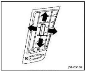
text_image
JVM0510X
text_image
Centerventulators JNHS11XSide ventilators

text_image
SE JPH0574XRearventilators
Openorclose, and adjust the airflow direction of ventilators.
☒: This symbol indicates that the ventilators are closed.
: This symbol indicates that the ventilators are open.
- Donotplacemetalizedfilmneartherear windowglassorattachanymetalparts tolt.Thismaycausepoorreceptionor noise.
- Whencleaningtheinsideoftherear window,becarefulnottoscratchor damagetherearwindowantenna. Lightlywipealongtheantennawitha dampenedsoftcloth.

natural_image
Simple line drawing of a 3D geometric shape resembling a truncated cone or frustum (no text or symbols)SATELLITEANTENNA
Thereisasatelliteantennaontherearpart ofthevehicleroof.
Abuildupoficeonthesatelliteradio antennacanaffectsatelliteradioperformance. Removetheicetorestoresatellite radioreception.
WheninstallingacarphoneoraCBradio inyourvehicle,besuretoobservethe followingcautions,otherwisethenew equipmentmayadverselyaffecttheelectroniccontrolmodulesandelectroniccontrolsystemharness.

WARNING
- Acellularphoneshouldnotbeusedfor anypurposewhiledrivingsofullattentionmaybegiventovehicleoperation. Somejurisdictionsprohibittheuseof cellularphoneswhiledriving.
- If you must make all while your vehicle is in motion, the hands-free cellular phone operational mode (if so equipped) is highly recommended. Exercise extremecution at all times soful attention may begin to vehicle operation.
- Ifaconversationinamovingvehicle requiresyoutotakenotes,pulloffthe roadtoasafelocationandstopyour vehiclebeforedoingso.

Monitor, climate, audio, phone and voice recognition systems

CAUTION
- Keeptheantennaasfarawayas possiblefromtheelectroniccontrol modules.
- Keeptheantennawiremorethan8in (20cm)awayfromtheelectroniccontrol systemharness.Donotroutetheantennawirenexttoanyharness.
- Adjusttheantennaslanding-waveratio asrecommendedbythemanufacturer.
- ConnectthegroundwirefromtheCB radiochassistothebody.
•Fordetails,consultanINFINITretailer.

Information Provided by DEALER
5Startinganddriving
Precautionswhenstartinganddriving....5-3
Exhaustgas(carbonmonoxide)....5-3
Three-waycatalyst....5-4
TirePressureMonitoringSystem(TPMS)......5-4
Avoidingcollisionandrollover....5-8
Off-roadrecovery....5-8
Rapidairpressureloss....5-9
Drinkingalcohol/drugsanddriving....5-9
IntelligentAll-WheelDrive(AWD)drivingsafety
precautions(AWDmodels)....5-10
Push-buttonignitionswitch....5-10
Operatingrangeforenginestartfunction.....5-11
Push-buttonignitionswitchoperation....5-11
Push-buttonignitionswitchpositions....5-12
Emergencyengineshutoff....5-12
IntelligentKeybatterydischarge....5-13
Beforestartingtheengine....5-13
Startingtheengine....5-14
Drivingthevehicle....5-15
Automatictransmission....5-15
Parkingbrake 5-20
INFINITI Drive Mode Selector 5-21
STANDARDmode 5-21
SPORT mode 5.22
SNOW mode 5-22
ECOmode....5-22
PERSONALmode....5-23
ActiveLaneControl(ifsoequipped)......5-24
PrecautionsonActiveLaneControl....5-26
ActiveLaneControloperation....5-27
Automaticdeactivation....5-29
Lanecameraunitmaintenance....5-29
LaneDepartureWarning(LDW0system/Lane
DeparturePrevention(LDP)system(if
soequipped)....5-30
LaneDepartureWarning(LDW)system....5-31
LaneDeparturePrevention(LDP)system....5-33
Systemmaintenance 5-36
BlindSpotWarning/BlindSpotIntervention TM/
Bank-unCollisionInterventionsystems.If
Back upcclusion/interventionsystems(in reconfigured)
BlindSnetWarning(RSW)system (Blind
BlindSpotWarning(BSW)system;Blind
SpotIntervention™ (BSI)system....5-37
BSW/BSIdrivingsituations....5-43
Back-upCollisionIntervention
(BCI)system....5-48
System maintenance.... 5-55
Cruise control (if so equipped).... 5-56
Precautionsoncruisecontrol....5-56
Cruise control operations 5-57

IntelligentCruiseControl(ICC)system(if
soequipped)....5-58
Selectingthevehicle-to-vehicledistance
controlmode....5-59
Vehicle-to-vehicledistancecontrolmode......5-59
Precautionsonvehicle-to-verifiedistance control mode
controlmode....5-60
vehicle-to-verifiedistancecontrol modeneration 5-61
Conventional(fixedspeed)cruise
controlmode....5-74
DistanceControlAssist(DCA)system(if
soequipped)....5-79
PrecautionsonDCAsystem....5-79
DCAsystemoperation....5-81
Forwardemergencybrakingsystem(if
soequipped)....5-89
Systemoperation....5-90
Predictiveforwardcollisionwarningsystem(if
soequipped....5-94
Systemoperation....5-95
Break-inschedule....5-99
FuelEfficientDrivingTips....5-99
Increasingfueleconomy....5-100
IntelligentAll-WheelDrive(AWD)(if
so equipped) 5-101
Parking/parkingonhills....5-103
Powersteering....5-104
Hydraulicpowersteeringtype....5-104
Directadaptivesteeringtype....5-104
Brakesystem....5-106
Brakingprecautions....5-106
Parkingbrakebreak-in....5-106
Brakeassist....5-107
Brakeassist....5-107
Anti-lockBrakingSystem(ABS)......5-107
VehicleDynamicControl(VDC)system....5-108
Brakeforcedistribution....5-109
Activetracecontrol....5-110
HillStartAssistsystem....5-111
Chassiscontrol....5-112
Coldweatherdriving....5-112
Freeingafrozendoorlock....5-112
Antifreeze....5-112
Battery....5-112
Draining of coolant water....5-112
Tireequipment....5-112
Specialwinterequipment....5-113
Drivingonsnoworice....5-113
Engineblockheater(ifsoequipped)......5-113
PRECAUTIONSWHENSTARTINGAND
DRIVING

WARNING
- Donotleavechildrenoradultswho wouldnormallyrequirethesupport of othersaloneinyourvehicle. Petsshould notbeleftaloneeither. Theycould accidentallyinjurethemselvesvorothers throughinadvertentoperationofthe vehicle. Also, onhot, sunnydays, temperaturesinaclosedvehiclecould quicklybecomehighenoughtocause severeorpossiblyfatalinjuriesto peopleoranimals.
Closelysupervisechildrenwhentheyare aroundcarstopreventthemfromplayingandbecominglockedinthetrunk wheretheycouldbeseriouslyinjured. Keepthecarlocked,withtherear seatbackandtrunklidsecurelylatched whennotinuse,andpreventchildren's accesstocarkeys.
EXHAUSTGAS(carbonmonoxide)

WARNING
- Donotbreatheexhaustgases;they containcolorlessandodorlesscarbon monoxide. Carbonmonoxideisdangerous.Itcancauseunconsciousnessor death.
■Ifyoususpectthatexhaustfumesare enteringthevehicle,drivewithall windowsfullyopen,and havethe vehicleinspectedimmediately.
- Donotruntheengineinclosedspaces suchasagarage.
- Donotparkthevehiclewiththeengine runningforanyextendedlengthoftime.
- Keepthetrunklidclosedwhiledriving, otherwiseexhaustgasescouldbedrawn intothepassengercompartment.Ifyou mustdrivewiththetrunklidopen, followtheseprecautions:
2) Set the air recirculation to off and the fan control to high to circulate the air.
- Ifelectricalwiringorothercableconnectionsmustpasstatrailerthrough thesealonthetrunklidorthebody, followthemanufacturer'srecommendationtopreventcarbonmonoxideentry intothevehicle.
•Theexhaustsystemandbodyshouldbe inspectedbyaqualifiedmechanicwhenever:
— Thevehicleisraisedforservice.
— Yoususpectthatexhaustfumesare enteringintothepassengercompartment.
— Younoticeachangeinthesoundof theexhaustsystem.
— Youhavehadanaccidentinvolving damagetotheexhaustsystem, underbody,orrearofthevehicle.
THREE-WAYCATALYST
The three-way catalyst is an emission control device installed in the exhaust system. Exhaust gases in the three-way catalyst are burned at light temperature to help reduce pollutants.

WARNING
•Theexhaustgasandtheexhaustsystem areveryhot.Keeppeople,animalsor flammablematerialsawayfromthe exhaustsystemcomponents.
- Donotstoporparkthevehicleover flammablematerialssuchasdrygrass, wastepaperorrags. They may ignite and cause a fire.

CAUTION
- Donotuseleadedgasoline.Deposits from leadedgasolineseriouslyreduce the three-way catalyst's ability to help reduceexhaustpollutants.
- Keepyourenginetunedup.Malfunctions intheignition,fuelinjection,orelectricalsystemscancauseoverrichfuel
flowintothethree-waycatalyst, causing ittooverheat. Donotkeepdrivingifthe enginemisfires, orlfnoticeablelossof performanceorotherunusualoperating conditionsaredetected. Havethevehicle inspectedpromptlybyanINFINITlretailer.
- Avoiddrivingwithanextremelylowfuel level. Runningoutoffuelcouldcause theenginetomisfire,damagingthe three-waycatalyst.
■Donotracetheenginewhilewarmingit up.
- Donotpushortowyourvehicletostart theengine.
TIREPRESSUREMONITORING SYSTEM(TPMS)
Each tire, including the spare (if provided), should be checked monthly when cold and inflated to the inflation pressure recommended by the vehicle manufacturer on the vehicle placard or tire inflation pressure label. (If your vehicle has tires of a different size than the size indicated on the vehicle placard or tire inflation pressure label, you should determine the proper tire inflation pressure for those tires.)
As an added safety feature, your vehicle has been equipped with a Tire Pressure Monitoring System (TPMS) that illuminates alow tire pressure telltalewhenone or more of your tires is significantly underinflated. Accordingly, when the low tire pressure telltaleilluminates, you should stop and check your tires as soon as possible, and inflate them to the proper pressure. Driving on a significantly under-inflated tire causes the tire to overheat and can lead to tire failure. Under-inflation also reduces fuel efficiency and tire treadlife, and may affect the vehicle's handling and stopping ability.
If the vehicle is being driven with one or moreflattires,thelowtirepressure warning light will illuminate continuously andachimewillsoundfor10seconds.The flattirewarningwillalsoappearinthe vehicleinformationdisplay.Thechimewill onlysoundatthefirstindicationaflat tire, and the warning light will illuminate continuously.Whentheflattirewarningis activated, have the system reset and the tirecheckedandreplacedifnecessarby anINFINITiretail.Evenithetireis inflatedtothespecifiedCOLDtirepres-sure, the warninglightwill continueto
5-4 Starting and driving
illuminateuntilthesystemisresetbyan INFINITretailer.Yourvehiclecanbedriven foralimitedtimeonaflattire.See"Run-flattires"(P.8-35).
PleasenotethattheTPMSisnota substituteforpropertiremaintenance, anditisthedriver'sresponsibility to maintaincorrecttirepressure,evenif under-inflationhasnotreachedthelevel totriggerilluminationoftheTPMSlowtire pressuretelltale.
Yourvehiclehasalsobeenequippedwitha TPMSmallfunctionindicatorindicate whenthesystemisnotoperatingproperly. TheTPMSmallfunctionindicatoriscombinedwiththelowtirepressuretelltale. Whenthesystemdetectsamalfunction, thetetellatawillflashforapproximatelyone minuteandthenremaincontinuously illuminated. Thissequencewillcontinue uponsubsequentvehiclestart-upsaslong asthemalfunctionexists. Whenthemalfunctionindicatorisilluminated, thesystemmaynotbeabletodetectorsnallow tirepressureasintended.TPMSmallfunctionsmayocurforvarietyofreasons, includingtheinstallationofreplacementer alternatetiresrowhelsonthevehichlet that preventtheTPMSfromfunctioningprop-
erly.AlwayschecktheTPMSmalfunction telltaleafterreplacingoneormoretiresor wheelsonyourvehicletoensurethatthe replacementoralternatetiresandwheels allowtheTPMStocontinuetofunction properly.
Additionalinformation
■TheTPMSdoesnotmonitorthetire pressureofthesparetire(ifso equipped).
- TheTPMSwillactivateonlywhenthe vehicleisdrivenatspeedsabove16 MPH(25km/h).Also,thissystemmay notdetectasuddendropintire pressure(forexampleaflattirewhile driving).
- Thelowtirepressurewarninglightdoes notautomaticallyturnoffwhenthetire pressureisadjusted. After theireis inflated totherecommended pressure, the vehicle must bedrivenatspeeds above 16MPH (25km/h)toactivatethe TPMSandturnoffthelowtirepressure warninglight. Use tire pressure gauge to check the tire pressure.
- The "Tire Pressure Low - Add Air" warning appears in the vehicle information display when the low tire pressure
warninglightisilluminatedandlowtire pressureisdetected.The"TirePressure Low-AddAir"warningturnsoffwhen thelowtirepressurewarninglight turnsoff.
The "TirePressureLow-AddAir" warningdoesnotappearifthelowtire pressurewaminglightilluminatesto indicateaTPMSmallfunction.
- The "FlatTire-Visitdealer" warning appears in the vehicle information display when the low tire pressure warning light is illuminated and done more or more flattires are detected.
- Tirepressurerisesandfallsdepending ontheheatcausedbythevehicle's operationandtheoutsidetemperature. Lowoutsidetemperaturecanlowerthe temperatureoftheairinsidethetire whichcancausealowertireinflation pressure.Thismaycausethelowire pressurewarglinglighttoilluminate.If thewarninglightilluminatesinlow ambienttemperature,checkthetire pressureforallfournires.
- You can also check the pressure of all tires (except the spare tire) in the vehicle information display. (See "Vehicle information display" (P.2-20).)
For additional information, see "Lowtire pressure warning light" (P.2-14) and "Tire Pressure Monitoring System (TPMS)" (P.6-3).

WARNING
•Radiowaves could adversely affect electric medicalequipment. Those who use apacemakers should contact the electric medicalequipment manufacturer for the possible influences before use.
- Ifthelowtirepressurewarninglight illuminateswhiledriving,avoidsudden steeringmaneuversorabruptibraking, drivevehiclespeed,pullofftheroadto asafelocuandstopthevehleveas soonaspossible.Drivingwithunder-inflatedtresmaypermanentlydamage thetiresandincreasethikelikelihood of tirefailure.Seriousvicedamage couldoccurandmayleadtoanaccident andcouldresultinseriouspersonal injury. Checktheirepressurerefall fourties.Adjusttheitrepressurerothe recommendedCOLDtirepressureshown ontheTireandLoadingInformation labeloturnthelowtirepressure warninglightOFF.Ifthelightstill
5-6 Starting and driving
illuminateswhiledrivingafteradjusting the tirepressure,atiremaybeflat.If youhaveaflattire,replaceltwitha sparetire(Ifsoequipped).(See"Flat tire"(R 6.3)forhearingeflattire).
Although you can continued driving with a punctured run-flattire, remember that vehicle handling stability is reduced, which could lead to an accident and personal injury. Also, driving along distance at high speed may damage the tires.
- Donotdriveatspeedsabove50MPH (80km/h)anddonotdrivemorethan approximately93miles(150km)witha puncturedrun-flattire. Theactualdistancethevehiclecanbedrivenonaflat tiredependsonoutsidetemperature, vehicleload,roadconditionsandother factors.
- If you detect any unusual sounds or vibrations while driving with punctured run-flattire, pullofftheroadtoasafe location and stop the vehicle as soon as possible. The tire may be seriously damaged and need to be replaced.
- When a spare tire is mounted or a wheel is replaced, the TPMS will not function
andthelowtirepressurewarninglight willflashforapproximately1minute. Thelightwillremainonafter1minute. ContactyourINFINITretailerassoonas possiblefortirereplacementand/or systemresetting.
- Replacing tires with those not originally specified by INFINIT could affect the proper operation of the TPMS.
- Donotinjectanytireliquidoraerosol tiresealantintothetires,asthismay causeamalfunctionofthetirepressure sensors.

CAUTION
•TheTPMSmaynotfunctionproperly whentewheelsareequippedwithtire chainsorthewheelsareburiedinsnow.
- Donotplacemetalizedfilmoranymetal parts(antenna,etc.)onthewindows. Thismaycausepoorreceptionofthe signalsfromthetirepressuresensors, andtheTPMSwillnotfunctionproperly.
Somedevicesandtransmittersmaytemporarilyinterferewiththeoperationofthe
TPMSandcausethelowtirepressure warninglighttoilluminate. Some examples are:
●Facilitiesorelectricdevicesusingsimilarradiofrequenciesarenearthe vehicle.
- Ifatransmittersettosimilarfrequenciesisbeingusedinornearthe vehicle.
- Ifacomputer(orsimilarequipment)or aDC/ACconverterisbeingusedinor nearthevehicle.
FCCNotice:
ForUSA:
ThisdevicecomplieswithPart15ofthe FCCRules.Operationissubjecttothe followingtwoconditions:
-
This device may not cause harmful interference, and
-
This device must accept any interference received, including interference that may cause undesired operation.
NOTE:
Changesormodificationnotexpressly approvedbythepartyresponsiblefor compliancecouldvoidtheuser's authoritylooperatetheequipment.
ForCanada:
This device complies with RSS-210 of Industry Canada. Operation is subject to the following two conditions:
-
This devicemaynotcauseinterference, and
-
This device must accept any interference, include interference that may cause undesired operation of the device.
TPMSwithTireInflationIndicator Whenaddingairtoanunder-inflatedtire, theTPMSwithTireInflationIndicator providesvisualandaudiblesignalsoutsidethevehicletohelpyouinflatethetires lotherecommendedCOLDtirepressure.
Vehicleset-up:
-
Parkthevehicleinasafeandlevel place.
-
Apply the parking brake and placethe shift lever in the P(Park) position.
-
PlacetheignitionswitchintheON position.Donotstarttheengine.
Operation:
-
Add air to the tire.
-
Afterafewseconds, the hazard indicators will start flashing.
-
When the designated pressure is reached, the horn beepsonce and the hazard indicators stop flashing.
-
Perform the abovestepsforeachtire.
- If the treisover-inflated more than approximately 4 psi (30 kPa), the horn beeps and the hazard indicators flash 3 times. I correct the pressure, push the core of the valvestemon the tire briefly to release pressure. When the pressure reaches the designated pressure, the horbeepsonce.
- If the hazard indicator does not flash within approximately 15 seconds after starting to inflate the tire, it indicates that the tire inflation indicator is not operating.
●TheTPMSwillnotactivatetheTire InflationIndicatorunderthefollowing conditions:
—Ifthereisinterferencefroman
externaldeviceortransmitter
—The airpressure from the inflation devices such as those using a power socket is not sufficient to inflate the tire
-Ifanelectricalequipmentisbeing usedinornearthevehicle -ThereisamalfunctionintheTPMS system -Thereisamalfunctioninthehorno hazardindicators
- IftheTireInflationIndicatordoesnot operateduetoTPMSinterference, movethevehicleabout3ft(1m) backwardorforwardandtryagain. IftheTireInflationIndicatorisnotworking, useatirepressuregauge.
AVOIDINGCOLLISIONANDROLL-OVER

WARNING
Failuretooperatethisvehicleinasafeand prudentmannermayresultinlossofcontrol oranaccident.
Bealertanddrivedefensivelyataalltimes. Obeyalltrafficregulations.Avoidexcessivespeed,highspeedcornering,or sudden steeringmaneuvers,because thesedrivingpracticescouldcauseyouto losecontrolofyourvehicle.Aswithany vehicle,alossofcontrolcouldresultina
5-8 Starting and driving
collisionwithothervehiclesorobjects,or causethevehicletorollover,particularlylf thelossofcontrolcausesethevehicleto slidesideways.Beattentiveatalltimes, andavoiddrivingwhentired.Neverdrive whenundertheinfluenceofalcohol drugs(includingprescriptionorover-the-counterdrugswhichmaycausedrowsiness).Alwayswearyourseseatbeltas outlinedinthe"Seatbelts"(P.1-12)ofthis manual, andalsoinstructyourpassengers todos.
Seatbeltshelpreducetheriskofinjuryin collisionsandrollovers.Inarollovercrash, anunbeltedorimproperlybeltedpersonis significantlymorelikelytobeinjuredor killedthanapersonproperlywearinga seatbelt.
OFF-ROADRECOVERY
Ifdrivingtherightsideorleftsidewheels mayunintentionallyleavetheroadsurface. Maintain controlofthevehiclebyfollowing theprocedurebelow.Pleasenotethatthis procedureisonlyageneralguide.The vehicle must be driven as appropriate based on the conditions of the vehicle, roadand traffic. Information Provided by
-
Remain calm and do not overreact.
-
Donotapplythebrakes.
-
Maintain a firm grip on the steering wheel with both hands and try to hold a straight course.
-
When appropriate, slowly releasethe acceleratorpedaltogradually slow the vehicle.
-
If there is nothing in the way, steer the vehicle to follow the road while the vehicles speed is reduced. Donot attempt to drivethe vehicle back onto the roads surface until vehicles speed is reduced.
-
When it's a fetodoso, gradually turn the steering wheel until both tires return to other roads surface. When all tires are on other roads surface, steer the vehicle to stay in the appropriate driving lane.
- If you decide that it is not safeto return the vehicle to other roads surface based on vehicle, road traffic conditions, gradually slow the vehicle to as topinasafe place off the road.
RAPIDAIRPRESSURELOSS
Rapidairpressurelossora"blow-out"can occurifthetireispuncturedorisdamaged duetohittingacurborpothole.Rapidair pressurelosscanalsobecased by drivingonunder-inflatedtires.
Rapidairpressurelosscanaffectthe handlingandstabilityofthevehicle, especiallyathighwayspeeds.
Helppreventrapidairpressurelossby maintainingthecorrectairpressure and visuallyinspectthetiresforwear and damage. See "Wheelsandtires"(P.8-29) of this manual.
Ifatirerapidlylosesairpressureor "blows-out"whiledrivingmaintaincontrol ofthevehiclebyfollowingtheprocedure below.Pleasenotethatthisprocedureis onlyageneralguide.Thevehiclemustbe drivenasappropriatebasedontheconditionsofthevehicle,roadandtraffic.

WARNING
The following actions can increase the chance of losing control of the vehicle if there is sudden loss of fire air pressure. Losing control of the vehicle may cause a
collisionandresultinpersonalinjury.
•Thevehiclegenerallymovesorpullsin thedirectionoftheflattire.
- Donotrapidlyapplythebrakes.
- Donotrapidlyreleasetheaccelerator pedal.
•Donotrapidlyturnthesteeringwheel.
1.Remaincalmanddonotoverreact.
- Maintainafirmgriponthesteering wheelwithbothhandsandtrytoholda straightcourse.
- When appropriate, slowly releasethe acceleratorpedaltogradually slow the vehicle.
- Graduallysteerthevehicletoasafe locationofftheroadandawayfrom trafficifpossible.
- Lightly apply the brake pedal gradually stop the vehicle.
- Turnonthehazardwarningflashers andeithercontact aroadside emergency service to change the tire or see "Changing a flat tire" (P.6-4) of this Owner's Manual.
DRINKINGALCOHOL/DRUGSAND DRIVING

WARNING
Neverdriveundertheinfluenceofalcoholor drugs. Alcoholinthebloodstreamreduces coordination, delaysreactiontimeandimpairsjudgement. Drivingafterdrinking alcoholincreasesthelikelihoodofbeing involved in accident injurying yourself and others. Additionally, if you are injured in an accident, alcohol can increase the severity of their injury.
INFINITliscommittedtosafedriving. However, you must choose nottodrive under the influence of alcohol. Every year thousands of people are injured or killed in alcohol-related accidents. Although the callaws vary on what is considered to be legally intoxicated, the fact that alcohol affects all peopled differently and most people underestimate the effect of alcohol.
Remember, drinking and driving don't mix! And that ist rue for drugs, too (over-the-counter, prescription, and illegal drugs).
PUSH-BUTTONIGNITIONSWITCH
Don't drive if your ability to operate your vehicle is impaired by alcohol, drugs, or some other physical condition.
INTELLIGENTALL-WHEELDRIVE (AWD)DRIVINGSAFETYPRECAUTIONS(AWDmodels)

WARNING
- Donotdrivebeyondtheperformance capabilityofthetires,evenwithIntelligentAWDengaged.Acceleratingquickly, sharpsteeringmaneuversorsudden brakingmaycauselossofcontrol.
●Alwaysusetiresofthesametype,size,brand,construction(bias,bias-beltedor radial),andtreadpatternallfour wheels.Installtirechainsontherear wheelswhendrivingonslipperyroads anddrivecarefully. - Thisvehicleisnotdesignedforoff-road (roughroad)use.Donotdriveonsandy ormuddyroadsthattiresmaygetstuck in.
- ForAWDequippedvehicles, donot attempttoraisetwowheelsoffthe groundandshiftthetransmissionto
anyD(Drive)orR(Reverse)positionwith theenginerunning.Doingsomayresult Indrivetralndamageorunexpected vehiclemovementwhichcouldresultin seriousvehicledamageorpersonal injury.
- DonotattemptlotestanAWDequipped vehicleona2-wheeldynamometer(such asthedynamometersusedbysome statesforemissionstesting),orsimilar equipmenteveniftheothertwowheels areraisedofftheground.Makesureyou informtestfacilitypersonnelthatyour vehicleisequippedwithAWDbeforeitis placedonadynamometer.Usingthe wrongtestequipmentmayresultin drivetraindamageorunexpectedvehicle movementwhichcouldresultinserious vehicledamagedeopersonalInjury.
- Whenawheelisoffthegroundduetoan unlevelsurface, donotspinthewheel excessively.

WARNING
Donotoperatethepush-buttonignition switchwhiledrivingthevehicleexceptinan emergency.(Theenginewillstopwhenthe ignitionswitchispushed3consecutive timesorthelnignitionswitchispushed and heldformorethan2seconds.)Iftheengine stopswhilethevehicleisbeingdriven,this couldleadtoacrashandseriousinjury.
Beforeoperating the push-button ignition switch, besuretomovetheshiftleverto the P(Park) position.

5-10 Startinganddriving
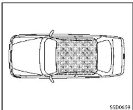
natural_image
Top-down line drawing of a car with no text, numbers, or symbolsThe Intelligent Keycanonlybeused for starting the engine when the Intelligent Key is within the specified operating range. When the Intelligent Key battery is almost discharged for strong radiowaves are present near the operating location, the Intelligent Keysystem's operating range becomes narrower and may not function properly.
If the Intelligent Key is within the operating range, it is possible for anyone, even some onewh does not carry the Intelligent
Key, topushtheignitionswitchtostartthe engine.
- Thetrunkareaisnotincludedinthe operatingrangebutthelntelligentKey mayfunction.
- If the Intelligent Key is placed on the instrument panel, rear parcel shelf, insidethe glovebox door pocket, the Intelligent Key may not function.
- If the Intelligent Key is placed near the door or window outside the vehicle, the Intelligent Key may function.

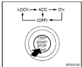
flowchart
graph TD
    A["LOCK"] --> B["ACC"]
    B --> C["ON"]
    C --> D["(OFF)"]
    D --> E["START STOP 126°"]
    E --> F["JV50241X"]
PUSH-BUTTONIGNITIONSWITCH OPERATION
Whentheignitionswitchispushedwithout depressingthebrakepedal,theignition
switchpositionwillchangeasfollows:
●PushcenteroncetochangetoACC,
●PushcentertwotimestochangetoON.
●Pushcenterthreetimestochanger OFF.(Nopositionilluminates.)
- PushcenterfourtimestoreturntoACC.
- Openorcloseanydoortoreturnto LOCKduringtheOFFposition.
If the battery of the vehicle is discharged, the push-buttonignitions switch cannot be turned from the LOCK position.
Some indicators and warnings for operation are displayed in the vehicle information display between the speedometer and tachometer. (See "Vehicle information display" (P.2-20).)
The ignitionlock is designed so that the ignitionswitch position cannot be switched to LOCK until the shift lever is moved to the P(Park) position.
Whentheignitionswitchcannotbepushed towardtheLOCKposition,proceedas follows:
-
MovetheshiftleverintotheP(Park) position.
-
PushtheignitionswitchtotheOFF position. Theignitionswitchposition indicatorwillnotilluminate.
-
Openthedoor. Theignitionswitchwill changetotheLOCKposition.
TheshiftlevercanbemovedfromtheP (Park)positioniftheignitionswitchisin theONpositionandthebrakepedalis depressed.
PUSH-BUTTONIGNITIONSWITCH POSITIONS
LOCK(Normalparkingposition)
Theignitionswitchcanonlybelockedin thisposition.
Theignitionswitchwillbeunlockedwhen itispushedtotheACCpositionwhile carryingtheIntelligentKey.
ACC(Accessories)
Thispositionactivateselectricalaccessories such as a stheradio, when the engine is not running.
ON(Normaloperatingposition)
Thispositionturnsontheignitionsystem andelectricalaccessories.
OFF
Theenginecanbeturnedoffinthis position.
The ignitionlockisdesignedsothatthe ignitionswitchcannotbeswitchedtothe LOCKpositionuntiltheshiftleverismoved totheP (Park) position.

CAUTION
Donotleavethevehiclewiththepush-buttonignitionswitchInACCorONpositionswhentheengineisnotrunningforan extendedperiod.Thisdischargethe battery.
EMERGENCYENGINESHUTOFF
Toshutofftheengineinanemergency situationwhiledriving,performthefollowingprocedure:
●Rapidlypushthepush-buttonignition switch3consecutivetimesinlessthan 1.5seconds,or
- Pushandholdthepush-buttonignition switchformorethan2seconds.
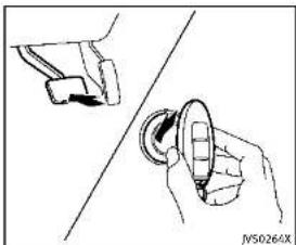
natural_image
Illustration of a hand holding a circular object with an arrow, next to a mechanical component (no text or symbols)INTELLIGENTKEYBATTERYDISCHARGE
If the battery of the Intelligent Key is discharged, orenvironmental conditions interferewith the Intelligent Key operation, start the engine according to the following procedure:
- MovetheshiftlevertotheP(Park) position.
2.Firmlyapplythefootbrake.
-
Touchtheignitionswitchwiththe IntelligentKeyasillustrated.(Achime willsound.)
-
Pushtheignitionswitchwhiledepressingthebrakepedalwithin10seconds afterthechimesounds.Theenginewill start.
After step 3 is performed, when the ignitionswitch is pushed without depressing the brake pedal, the ignitionswitch position will change to ACC.
NOTE:
- Whentheignitionswitchpushed to theACCorONpositionortheengineis startedbytheaboveprocedures,the IntelligentKeybatterydischargeindicatorappearsinthevehicleinformationdisplayeveniftheIntelligentKey isinsidethevehicle.Thisisnota malfunction.ToturnofftheIntelligent Keybatterydischargeindicator,touch theignitionswitchwiththeIntelligent Keyagain.
- If the Intelligent Keybattery discharge indicator appears, replacethe battery as soon as possible. (See "Intelligent Keybattery replacement" (P.8-24).)

BEFORESTARTINGTHEENGINE
●Makesuretheareaaroundthevehicle isclear.
- Checkfluidlevelssuchasengineoil, coolant, brakefluid and window washerfluid as frequently as possible, or at least whenever you refuel.
- Check that all windows and lights are clean.
- Visuallyinspecttiresfortheirappearanceandcondition.Alsochecktiresforproperinflation.
- Lockalldoors.
- Positionseatandadjustheadrestraints.
-Adjustinsideandoutsidemirrors.
●Fastenseatbeltsandaskallpassengerstodolikewise.
- Check the operation of warning lights when the ignition switch is pushed to the ON position. (See "Warning/indicator lights and audibler reminders" (P.2-12).)
STARTINGTHEENGINE
- Apply the parking brake.
2.MovetheshiftlevertotheP(Park)orN (Neutral)position.(Pisrecommended.) Thestarterisdesignednottooperate unlessthesthiftleverisineitherofthe abovepositions.
- PushtheignitionswitchtotheON position.Depressthebrakepedaland pushtheignitionswitchtostartthe engine.
Tostarttheengineimmediately.push andreleasetheignitionswitchwhile depressingthebrakepedalwiththe ignitionswitchinanyposition.
- Iftheengineisveryhardtostartin extremelycoldweatherorwhen restarting, depresstheaccelerator pedalalittle(approximately1/3to thefloor)andwhileholding,crank theengine.Releasetheaccelerator pedalwhentheenginestarts.
- If the engine is very hard to start because it is flooded, depress the accelerator pedal all the way to the floor and hold it. Push the ignition switch to the ON position to start cranking the engine. After 5 or 6 seconds, stop cranking by pushing the ignition switch to OFF. After
5-14 Starting and driving
crankingtheengine, releasethe acceleratorpedal. Cranktheengine withyourfootoff theaccelerator pedalbydepressingthebrakepedal andpushingthepush-buttonignitionswitchtostarttheengine. If the enginestarts, butfailstorun, repeat theaboveprocedure.
CAUTION
Donotoperalethestarterformorethan15 secondsatatime.Iftheengineedsnot start,pushtheignitionswitchtoOFFand wait10secondsbeforecrankingagain, otherwisethestartercouldbedamaged.
4.Warm-up
Allowtheenginetoidleforatleast30 secondsafterstarting.Donotracethe enginewhilewarmingitup.Driveat moderatespeedforashortdistance first,especiallyincoldweather.Incold weather,keeptheenginerunningfora minimum of 2 - 3 minutes before shutting it off. Starting and stopping the engine over a short period of time may make the vehicle more difficult to start.
Whenracingtheengineupto4,500 rpmormoreundernoloadcondition, theenginewillenterthefuelcutmode
- Tostoptheengine, shift the shift lever to the P(Park) position and push the ignitions switch to the OFF position.
NOTE:
Careshouldbetakentoavoidsituations thatcanleadtopotentialbatterydischargeandpotentialno-startconditions suchas:
-
Installationorextendeduseofelectronicaccessoriesthatconsumebattery powerwhentheengineisnotrunning (Phonechargers,GPS,DVDplayers, etc.)
-
Vehicle is not driven regularly and/or only drivenshort distances.
In these cases, the battery may need to be charged to maintain battery health.
DRIVINGTHEVEHICLE
AUTOMATICTRANSMISSION
The automatic transmission in your vehicle is electronically controlled by a transmission control module to produce maximum efficiency and smooth operation.
Shownonthefollowingpagesarethe recommendedoperatingproceduresfor thistransmission.Followtheseprocedures formaximumvehicleperformanceand drivingenjoyment.
Startingthevehicle
Afterstartingtheengine,fullydepressthe footbrakepedalandpushtheshiftlever buttonbeforeshiftingtheshiftlevertothe R(Reverse),N(Neutral),D(Drive)or Manualshiftmodeposition.Besurethe vehicleisfullystoppedbeforeattempting toshifttheshiftlever.
ThisAutomaticTransmission(AT)modelis designedsothatthefootbrakepedal mustbedepressedbeforeshiftingfromP (Park)toanydrivepositionwhilethe ignitionswitchisintheONposition.
Theshiftlevercannotbemovedoutofthe P(Park)positionandintoanyoftheother gearpositionsifthelnitionswitchis pushedtotheLOCK,OffForACCposition.
- Keep the foot brake pedal depressed and push the shift lever button to shift into a driving gear.
- Releasetheparkingbrakeandfoot brake, thengraduallystartthevehicle inmotion.
WARNING
- Donotdepressstheacceleratorpedal while shifting from P(Park) or N(Neutral) to R(Reverse), D(Drive) or manual shift mode. Always depress the brake pedal until shifting is completed. Failure to dosocould causey out of close control and have an accident.
●Coldengineidlespeedishigh, souse cautionwhenshiftingintoaforwardor reversegearbeforetheenginehas warmedup.
■NevershifttoP(Park)orR(Reverse) whilevehicleismovingforward.Never shifttoP(Park)orD(Drive)whilevehicle ismovingrearward.Failureretodoso could cause you to lose control and have ana ccident.

CAUTION
- Whenstoppingthevehicleonanuphill grade, donotholdthevehicle by depressingtheacceleratorpedal. The footbrakeshouldbeusedforth this purpose.
- Donotdownshiftabruptlyonslippery roads. This may cause all loss of control.
- Exceptinanemergency, donotshift to the N(Neutral)positionwhiledriving. CoastingwiththetransmissionintheN (Neutral)positionmaycauseserious damagetothetransmission.
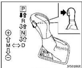
text_image
P R N D M + - JY50186XShiftlever
Tomovetheshiftlever,
→:Pushthebuttonwhiledepressingthe
brakepedal
Bushtnebutton
→: justmovetheshiflever.
Shifting
After starting the engine, fully depress the brake pedaland shift the shift lever from P (Park) to R (Reverse), N (Neutral), D (Drive) or Manual shift mode position. Push the button to shift into P (Park) or R (Reverse). All other positions can be selected without pushing the button.
WARNING
Apply the parking brake if the shift lever is in any position while the engine is not running. Failure to dos could cause the vehicle to move unexpectedly or roll away and result in serious personal injury or property damage.
CAUTION
Makesurethevehicleiscompletelystopped andthetransmissionisintheP(Park) position.
P(Park)position:
Usethispositionwhenthevehicleis parkedorwhenstartingtheengine.Make surethevehicleiscompletelystopped.The brakepedalmustbedepressedandthe shiftleverbuttonpushedintomovethe shiftleverfromtheN(Neutral)positionor any drive position to the P (Park) position. Apply the parking brake. When parking on a hill, apply the parking brake first, then move the shift lever to the P (Park)
position.
CAUTION
Use this position only when the vehicle is completely stopped.
R(Reverse):
Use this position to backup. Always be sure the vehicle is completely stopped before selecting the R(Reverse) position. The brake pedal must be depressed and the shift lever button pushed into move the shift lever from the P(Park) position, the N(Neutral) position or any drive position to the R(Reverse) position.
N(Neutral):
Neitherforwardnorreversegearisengaged. Theenginecanbestartedinthis position. You may shift to the N(Neutral) position and restart a stalled engine while the vehicle is moving.
D(Drive):
Use this position for all normal forward driving.
5-16 Startinganddriving
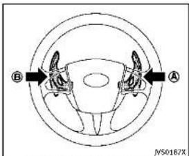
text_image
B A N50167XPaddleshifters(ifsoequipped)
Manualshiftmode
Whentheshiftleverisinthemanualshift gate, the transmission is ready for the manualshift mode. Shiftrangescanbe selected manually by moving the shift lever upordown, or pulling the right-side left-side paddleshifter (if soe equipped).
Whenshiftingup, movetheshiftleverto the+(up)sideorpulltheright-sidepaddle shifter(+) A (Ifsoequipped). The transmissionshiftstothehigherrange.
Whenshiftingdown, movetheshiftleverto the-(down)sideorpulltheleft-side paddleshifter(-) (B) (ifsoequipped).Th
transmissionshiftstothelowerrange. Whencancelingthemanualshiftmode, returntheshiftlevertotheD(Drive) position. The transmissionreturnstothe normaldrivingmode.
When you pull the paddles hifter (if so equipped) while the D(Drive) position, the transmission will shift to the upper or lower an get temporarily. The transmission will automatically return the D(Drive) position after a short period of time. If you want to return the D(Drive) position manually, pull and hold the paddles hifter for about 1.5 seconds.
Inthemanualshiftmode, theshiftrangeis displayed in the vehicle information display.
Shiftrangesupordownonebyoneas follows:
7^M (7th):
Use this position for all normal forward driving a t highway speeds.
6^M (6th) and 5^M (5th):
Use these positions when driving up long slopes, or for engine braking when driving
downlongslopes.
4^M (4th), 3^M (3rd) and 2^M (2nd):
Use these positions for hill climbing or engine braking on downhill grades.
1 ^M (1st):
Use this position when climbing steep hills slowly or driving slowly through deep snow, or maximum engine braking on steepdownhill grades.
- Remembernottodriveathighspeeds forextendedperiodsoftimeinlower than7thgear. Thisreducesfueleconomy.
- Movingtheshiftleverrapidlytothe samesidetwicewillshifttherangesin succession.
•Inthemanualshiftmode, the transmission may not shift to these selected gear or may automatically shift to the other gear. This helps maintain driving performance and reduce the chance of vehicle damage or loss of control.
- When the transmission does not shift to the selected gear, the Automatic Transmission (AT) position indicator (in the vehicle information display) will blink and the buzzer will sound.
•Inthemanualshiftmode, the transmission automatically shifts downto1st gear before the vehicle comestoa stop. When accelerating again, it is necessary to shift up to the desired range.
Acceleratordownshift—InD(Drive) position—
Forpassingorhillclimbing,fullydepress theacceleratorpedaltothefloor.This shiftsthetransmissiondownintothelower gear,dependingonthevehiclespeed.
Fail-safe
Whenthefail-safeoperationoccurs, note that the transmission will be locked in any of the forward gears according to the condition.
If the vehicle is driven under extreme conditions, such as excessive wheelspinning and subsequent hard braking, the fall safesystem maybe activated. This will occur even if a electrical circuit are functioning properly. In this case, push the ignition switch to the OFF position and wait for seconds. Then push the ignition switch back to the ON position. The vehicle should return to its normal operating condition. If it does not return to its
5-18 Startinganddriving
normaloperatingcondition, have an INFINITretailercheckthetransmission andrepairifnecessary.
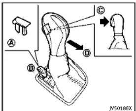
text_image
A B C D JVS0188XShiftlockrelease
If the battery charge is slow discharged, the shift lever may not be moved from the P (Park) position even with the brake pedal depressed and the shift lever button pushed.
Tomovetheshiftlever, perform the following procedure:
-
PushtheignitionswitchtotheOFFor LOCKposition.
-
Apply the parking brake.
-
Removetheshiftlockcover suitabletool.
Ⓐ usinga
4.Pushdowntheshiftlock mechanicalkeyasillustrated.
⑧ using
5.Pushtheshiftleverbutton movetheshiftlevertoN(Neutral) position ① whileholdingdownthe shiftlock.
If the lever cannot be moved out of P (Park), have an INFINIT retailer checked the automatic transmissionsystem as soon as possible.
AdaptiveShiftControl(ASC)
The adaptiveshift control system automatically operates when the transmission is in the D(Drive) position and selects an appropriate gear depending on the road condition such as uphill, downhill or curving roads.
Controlonuphillandcurvingroads:
Alowgearismaintainedthatsuits the degreeoftheslopeorcurvetoallow smoothdrivingwithasmallnumberof shifts.
Controlondownhillroads:
The adaptiveshift control system shift to alow gear that suits the degree of the slope, and uses the engine braking to reduce the number of times that the brake
mustbeused.
Controlonwindingroads:
Alowgearismaintainedoncontinuous curvesthatinvolverepeatedacceleration anddeceleration,sothatsmoothaccelerationisavailableinstantlywhentheacceleratorpedalisdepressed.
NOTE:
-Adaptiveshiftcontrolmaynotoperate whenthetransmissionoiltemperature islowimmediatelyafterthestartof drivingorwhenitisveryhot.
- Duringsomedrivingsituations, hard brakingforexample, the adaptiveshift controlmay automaticallyoperate. The transmission may automatically shift to alower gear forengine braking. This increases enginespeed but not vehicle speed. Vehiclespeed is controlled by the accelerator pedal when the vehicle is in the Adaptiveshift control mode.
- When the adaptiveshift control operates, the transmission sometimes maintains lower gear for longer period of time than when adaptive shift control is not operating. Engine speed will be higher for a specific vehicle speed while ASC system is operating
thanwhenASCisnotoperating.
NAVIShiftControl(ifsoequipped)
NAVIShiftControlautomaticallyadjusts theAutomaticTransmission(AT)gearpositionincertainsituationsbasedonroad informationfromthenavigationsystem.
When then navigationsystemdetects that the vehicle is approaching acurved road, NAVIShiftControl will adjust the gear position if needed to help the driver run through the curves smoothly.
PrecautiononNAVlshiftcontrol:
- The NAVIShiftControldoesnotprovide steeringinputorautomateddrivingon acurve. Itisnotaspeedlimitsupport systemandwillnotmodifyourspeed according to localspeedlimits.
●TheNAVISHiftControlisaconvenient systemintendedtohelpthevehicle movethroughacurvessmoothly. However, thedrivermustalwaysdrive safelyandusethebrakepedalif needed.
- The NAVIShiftControlmaybedelayed ornotoperateproperlyinthefollowing situations, because this function uses theroadinformationprovidedbythe navigation system.
Startinganddriving5-19
PARKING BRAKE
—When thenavigationsystem cannot accurately detect the location of the vehicle.
—Whenthevehicleisdrivingona roadwaythatisnotrecognizedby thenavigationsystem.
—When the actual roadway differs from themapinformation on the navigation system duetoroadconstruction, trafficlaneobstructions, etc.
●TheNAVIShiftControlmaynotoperate
property/intherollowingsituations: —Ifthevehicle'stransmission,engine, and/ornavigationsystem,and/or GPSismalfunctioning.
—If the vehicles speed is higher than 74MPH (120km/h) or lower than 19MPH (30km/h) and/or transmission gear is outside the operating range of the system.
—Whenthevehicleisdrivingona freeway.
—Whenthevehicleisdrivingona gentlecurve
—Whenthevehicleisdrivingwiththe shiftleverexceptintheD(Drive) position.
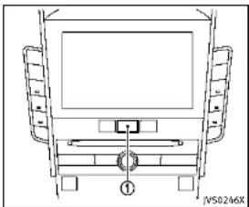
natural_image
Top-down schematic of a vehicle rear view showing front, rear, and side panels with no text or symbolsHowtoenable/disabletheNAVIShift
Control:
Perform the following step to enable or disable the NAVI shift control.
- Push the MENU button ① and touch [Settings] on the lower display.
- Touch[DriveModeEnhancement].
- Touch[NaviShiftControl] and select the ON(enabled) or OFF(disabled).
WARNING
- Besure the parking brake is fully released before driving. Failure to do so can cause brake failure and lead to an accident.
- Donotreleasetheparkingbrakefrom outsidethevehicle.
- Donotusethegearshiftinplaceofthe parkingbrake. Whenparking, besure theparkingbrakeisfullyengaged.
- Donotleavechildrenunattendedina vehicle. They could releasetheparking brake and cause an accident.

5-20Startinganddriving
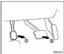
text_image
① ② SPA2331Toapply: Fully depress the parking brake pedal ①.
Torelease:
1.Firmlyapplythefootbrake

-
Depresstheparkingbrakepedal and the parking brakewillbereleased.
-
Before driving, besure the brake warning light goes out.
INFINITIDRIVEMODESELECTOR

text_image
DRIVE MODE JVSD180XINFINITIDriveModeSelector

text_image
STANDARD Information Provided by JVS0191MFivedrivingmodescanbeselectedby usingtheINFINITIDriveModeSelector (PERSONAL,SPORT,STANDARD,ECOand SNOW).
NOTE
WhentheINFINITIDriveModeSelector selectsamode, themodemaynotswitch immediately. This is not a malfunction.
Thecurrentmodeisdisplayedinthe vehicleinformationdisplay.Tochangethe mode, pushtheINFINITIDriveMode Selectorupordown.Themodelistwill appearontheupperdisplayandyoucan selectthemode.
PERSONAL↔SPORT↔STANDARD↔ECO ↔SNOW
Tosettheselectedmode, releasethe INFINITIDriveModeSelector. Themodelist will be turned off in approximately 5 seconds.
STANDARDMODE
Allowsforoptimumdrivingaccording to thedrivingconditions.
Thismodewillbeselectedfirsteachtime theengineisstarted.
SPORTMODE
Adjuststheengineandtransmission pointsforahigherresponse.Thesetting ofthesteeringsystemisadjustedto provideaquicksteeringresponseanda heavysteeringeffort.
NOTE:
IntheSPORTmode, fueleconomymaybe reduced.
SNOWMODE
Adjuststhedrivingforceforslipperyroads automatically.
ECOMODE
Assiststhedriver'seco-driving. The engine and transmission points are adjusted for improved fueleconomy, providing such a driving features a smooth starting or constant cruising.
NOTE:
SelectingtheECOmodewillnotnecessarilyimprovefueleconomyasmanydriving factorsinfluenceitseffectiveness.
Operation
SelecttheECOmodeusingtheINFINITI DriveModeSelector.TheECOdriveindicatorlightontheinstrumentpanelillumi-
5-22 Starting and driving
nates.
Whentheacceleratorpedalisdepressed withintherangeofeconomydrive,theECO driveindicatorlightilluminatesingreen. Whentheacceleratorpedalisdepressed abovetherangeofeconomydrive,theECO driveindicatorlightturnsoff.ForECO pedalsystemequippedmodels,see“ECO pedalsystem”(P.5-22).
The ECO drive indicator light will not illuminate in the following cases:
- WhentheshiftleverisintheR(Reverse) position.
- Whenthevehiclespeedisbelow2MPH (3.2km/h) or over 90MPH (144km/h).
- WhentheIntelligentCruiseControl(ICC) system(ifsoequipped)isoperated.
ECOpedalsystem(ifsoequipped)
The ECOpedalsystemhelpsassist the drivertoimprovefueleconomybyincreasingthereactionforceoftheaccelerator pedal. WhentheECOdriveindicatorlightis blinkingorremainsolf,theECOpedal system increases the reaction force of the accelerator pedal.

| ECO drive and cater light | Illuminate or black when |
| (illuminate (green)) | When the pedal is depressed within range of economy drive |
| (ECO) | When the pedal is co-expressed likely over the range of economy drive |
| Black (green) | |
| Not illuminate (off) | When the pedal is co-expressed over the range of economy drive |
WhentheECOdriveindicatorilluminatesin green, theacceleratorreactionforceis normal. WhentheECOdriveindicatorlight isblinkingorremainsoff, theECOPedal systemincreasesthereactionforceofthe acceleratorpedal.
The ECOpedalsystemmaynotvary acceleratorreactionforceunderthefollowing conditions:
- WhentheshiftleverisintheN(Neutral) orR(Reverse)position.
- When Intelligent Cruise Control (ICC) is being operated.
If the ECO pedalsystemmalfunctions, it will cancel automatically. The ECO pedal
systemwillnotvarythereactionforceof theacceleratorpedal.
WhentheINFINITIDriveModeSelectoris rotated from the ECOmodetoanother mode(STANDARD, SPORT, SNOWorPERSONAL) while the ECOpedalsystemis operating, the ECOpedalsystem continues to operate until the accelerator pedal is released.
If the accelerator pedal is depressed quickly, the ECOpedalsystem will not increasethereactionforce of the acceleration pedal. The ECOpedalsystem is not designed to prevent the vehicle from accelerating.
AdjustingtheECOpedalsystemreaction force:
The ECO pedalsystemreactionforce can be adjusted. Thereactionforcesetting will bemaintained until the setting is changed even if the engine is turned off.

natural_image
Top-down schematic of a vehicle rear view showing front, rear, and side panels (no text or symbols)SettingECOpedalreactionforce:
-
Push the MENU button ① and touch [Settings] on the lower display.
-
Touch[DriveModeEnhancement].
3.Touch[ECOPedal].
-
TosetthereactionforceoftheECO pedalsystem, touch[Standard]or [Soft].
-
TotumofftheECOpedalsystem, touch [OFF].
When the ECO pedal system is turned off, the accelerator will operate normally.
PERSONALMODE
When the PERSONAL mode is selected, the following functions can be adjusted individually.
●Engine-Transmission
- Steering(modelswiththedirectadaptivesteeringsystem)
●ActiveTraceControl

natural_image
Top-down schematic of a vehicle rear view showing front, rear, and side views (no text or labels)HowtosetthePERSONALmode
Perform the following step to set the PERSONAL mode.
- Push the MENU button ① and touch [InfinitiDriveModeSelector] on the lower display.
- Touch[Engine-Transmission], [Steering] or [ActiveTraceControl] and select each item. (See "Engine-Transmission", "Steering" and "Active Trace Control" about the feature of each item.)
- Touch[Back] or [Home] to finish the PERSONAL modesetting.
5-24Startinganddriving
ACTIVELANECONTROL(ifsoequipped)
Engine-Transmission:
"Engine-Transmission"canbesetto
[Sport],[Eco],[Standard]or[Snow].
Steering(modelswiththedirectadaptive
steeringsystem):
Fourcombinationsofsteeringeffortand
steeringresponsecanbeset.
| SteeringeffortSteeringresponse | |
| StandardStandard | |
| StandardQuick | |
| Heavy | Quick |
| Light | Casual |
ActiveTraceControl:
"ActiveTraceControl" can besetto ON
(enabled)orOFF(disabled).
FordetailsabouttheActiveTraceControl,
see"Activetracecontrol"(P.5-110).

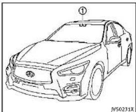
natural_image
Line drawing of a sedan car with front headlights and grille (no text or symbols)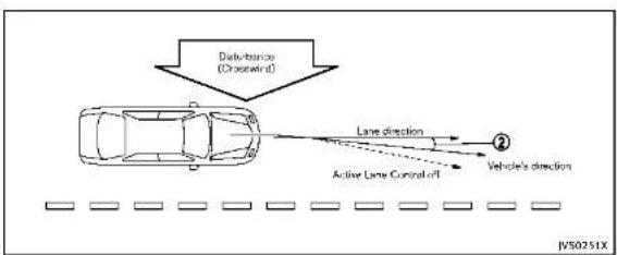
flowchart
graph TD
    A["Car"] -->|Data transmission (Crosscontrol)| B["Vehicle"]
    B --> C["Lane direction"]
    B --> D["Active Lane Control off"]
    C --> E["Direction ②"]
    D --> F["Direction ②"]
ActiveLaneControlslightlycorrectsfront tireanglesandsteeringwheeltorqueto helpreducethedifferencebetweenthe vehicle'sdirectionandthelanedirection ② whichisdetectedbyusingthecamera unit ① locatedabovetheinsidemirror.

Startinganddriving5-25
PRECAUTIONSONACTIVELANE CONTROL

WARNING
•ActiveLaneControlwillnotalwayssteer thevehicletokeepitlnthelane.itisnot designedtopreventlossofcontrol.itis thedriver'sresponsibilitytostayalert, drivesafely,keepthevehicleinthe travelinglane,andbeincontrolof vehicleatalltimes.
•ActiveLaneControlisprimarilyintended foruseonwell-developedfreewaysor highways.itmaynotdetectthelane markersforcertainroads,weatheror drivingconditions.
- UsingActiveLaneControlundersome conditionsofroad,lanemarkeror weather,orifyouattempttochange laneswithoutusingthelanechange signalcouldleadtoanunexpected systemoperation.Insuchconditions,youneedtocorrectthevehicle'sdirectionwithyoursteeringoperationto avoidaccidents.
- WhenActiveLaneControlisoperating, avoidexcessiveorsuddensteering
maneuvers. Otherwise, you could lose control of the vehicle.
•ActiveLaneControlwillnotoperateat speedsbelowapproximately45MPH(70 km/h)oriftcannotdetectlanemarkers.
●ActiveLaneControlmaynotoperate properlyunderthefollowingconditions, anddonotuseActiveLaneControl:
— Duringbadweather(rain,fog,snow, wind,etc.).
— Whendrivingonslipperyroads, suchasoniceorsnow,etc.
— Whendrivingonwindingoruneven roads.
— Whenthereisalaneclosuredueto roadrepairs.
- Whendrivinginamakeshiftlane.
- Whendrivingonroadswherethe lanewidthhistoonarrow.
— Whendrivingwithatirethatisnot withinnormaltireconditions(for example,tirewear,lowtirepressure, in stallation of spare tire, tire chains, non-standard wheels).
- When the vehicle is equipped with non-original steering parts or sus-
pensionparts.
- IfActiveLaneControlmalfunctions, it will cancel automatically. The chassis control warning will appear in the vehicle information display.
- If the chassis control warning appears, pullofftheroadtoasafelocation and stopthe vehicle. Turn the engine off and restart the engine. If the chassis control warning continues to illuminate, have Active Lane Control checked by an INFINIT retailer.
The functions of Active Lane Control may not operate properly under the following conditions:
- Onroadswheretherearemultiple parallellanemarkers;lanemarkers that are fadedomotpaintedclearly; yellowpaintedlanemarkers;non-standardlanemarkers;lanemarkerscoveredwithwater.dirt.snow etc.
- Onroadswherediscontinuedlane markersarestilldetectable.
- Onroadswheretherearesharpcurves.
- Onroadswheretherearesharply contrastingobjects,suchasshadows, snow,water,wheelruts,seamsorlines
remainingafterroadrepairs.(Active LaneControlcoulddetecttheseitems aslanemarkers.)
●Onroadswherethetravelinglane mergesorseparales.
- Whenthevehicle'stravelingdirection doesnotalignwiththelanemarker.
- Whentravelingclosetothevehiclein frontofyou, which obstructsthelane cameraunitdetectionrange.
- Whenrain, snowordirtadheresto the windshieldinfrontofthelanecamera unit.
- Whentheheadlightsarenotbrightdue todirtonthelensoriftheaimingisnot adjustedproperly.
- When strong light enter the helane camera unit. (Forexample, the light directly shines on the front of the vehicle at sunrise or sunset.)
- Whenasuddenchangeinbrightness occurs. (Forexample, whenthevehicle entersorexitsatunnelorundera bridge.)
■Whenenteringorexitingtollgates.
- Whendrivingonroadswithawidening ornarrowinglanewidth.
ActiveLaneControloperatesunderthe followingconditions:
- When the vehicle is driven at speed sof approximately 45 MPH (70 km/h) and above.
- When the Lane Departure Prevention (LDP) system is enabled in these settings menu on the lower display. To turn on the LDP system, see "Lane Departure Prevention (LDP) system" (P. 5-33).
- WhenActiveLaneControlisenabledin thesettingsmenuonthelowerdisplay.

natural_image
Technical line drawing of a mechanical component with a curved arrow and circular detail (no text or symbols)Dynamicdriverassistanceswitch
ActiveLaneControlturnsonwhenthe dynamicdriverassistanceswitchonthe steeringwheelispushedand[Activelane control]and[LaneDeparturePrevention] areenabledinthesettingsmenuonthe lowerdisplay.See“Howtoenable/disable theLDPsystem”(P.5-35).

Startinganddriving5-27
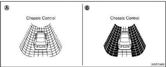
ThestatusofActiveLaneControlinthe
vehicleinformationdisplayisdisplayedas
follows.
■WhenActiveLaneControlisturnedon,
thechassiscontrol Ⓐ isdisplayed.
- WhenActiveLaneControlisoperational
orisoperating, thechassiscontrol
Isdisplayed.
Forsettingofchassiscontroldisplayinthe
vehicleinformationdisplay,seeInfiniti
InTouchOwner'sManual.
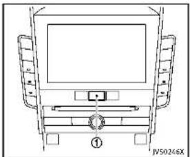
natural_image
Top-down schematic of a vehicle rear view showing front, rear, and side compartments (no text or symbols)ActiveLaneControlsettings
PerformthefollowingstepstosetActive
LaneControl.
- PushtheMENUbutton (1) andtouch
[DriverAssistance]onthelowerdis-
play.
2.Touch[LaneAssist].
- Touch[Activelanecontrol].
4 Touch[Activelanecontrolsettingland
select[Lowlor(High]tochangethe
settingofActiveLaneControl.
5-28 Starting and driving

NOTE:
IftheLaneDeparturePrevention(LDP)
systemsettingisOFF,ActiveLaneControl cannotbeoperated.TouseActiveLane Control,settheLDPsystemtoON.
AUTOMATICDEACTIVATION
ActiveLaneControlisnotdesignedto operateunderthefollowingconditions:
- When the Vehicle Dynamic Control (VDC) system(exceptTCS function) or ABSoperates.
- When you operate the helane change signal and can get the traveling lanes in the direction of the signal. (Active Lane Control is deactivated for approximately 2 seconds after the helane change signal is turned off.)
- Whenthevehiclespeedlowerstoless thanapproximately45MPH(70km/h).
- When the hazard warning flashers are operated.
Aftertheaboveconditionshavefinished andtheoperatingconditionsaresatisfied again,ActiveLaneControlwillresume operation.
Temporarydisabledstatusathigh temperature
Ifthevehicleisparkedindirectsunlight underhightemperatureconditions(over approximately 104°F(40°C))and then ActiveLaneControlisturnedon,Active LaneControlmaybedeactivatedautomatically.Thehighcabintemperaturemessagewillappearinthevehicleinformation display.
Actiontotake:
Whentheaboveconditionsnolongerexist, pushthedynamicdriverassistanceswitch againloturnActiveLaneControlbackon.


text_image
① S5D0453LANECAMERAUNITMAINTENANCE
Thelanecameraunit ① forActiveLane Controlislocatedabovetheinsidemirror. TokeeptheproperoperationofActiveLane Controlandpreventasystemmalfunction, besuretoobservethefollowing:
- Alwayskeepthewindshieldclean. - Donotattachasticker(including transparentmaterial)orinstallan accessorynearthecameraunit.
- Donotplacereflectivematerials, such as white paper or a mirror, on the instrumentpanel. Thereflectionof sunlightmayadverselyaffectthecam-
eraunit'scapabilityofdetectingthe lanemarkers.
- Donotstrikeordamagetheareas aroundthecameraunit.Donottouch thecameralensurremovethescrew locatedonthecameraunit.Ifthe cameraunitisdamagedduetoan accident,contactanINFINITlretailer.
LANEDEPARTUREWARNING(LDW) SYSTEM/LANEDEPARTUREPREVENTION (LDP)SYSTEM(ifsoequipped)
TheLaneDepartureWarning(LDW)system/LaneDeparturePrevention(LDP)systemwilloperatewhenthevehicleisdrivenatspeedsofapproximately45MPH(70km/h)andabove,andwhenitistravelingclosetoeithertheleftortherightofatravelinglane.
Eachsystemfunctionsasfollows:
●LaneDepartureWarning(LDW)system—warnsthedriverbythewarningin thevehicleinformationdisplayand chimethatthevehicleisbeginningto leavethedrivinglane.
●LaneDeparturePrevention(LDP)system —warnsthedriverbythewarningin thevehicleinformationdisplay and chime, and helps assistthedriverto returnthevehicletothecenterdirectionofthetravelinglanebyoperating thesteeringsystemtotherightorleft (forashortperiodoftime).
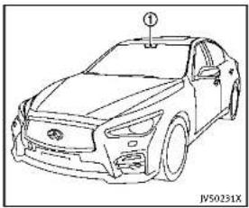
natural_image
Line drawing of a sedan car with no visible text or symbols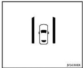
natural_image
Simple line drawing of a car with vertical bars and two wheels, no text or symbols presentDriverassistsystemlaneindicator
5-30 Starting and driving
TheLDWandLDPsystemsmonitorthelane markersonthetravelinglaneusingthe cameraunit ① locatedabovetheinside mirror. Whenthecameraunitdetectsthat thevehicleistravelingclosetoeitherthe leftortherightofthetravelinglane,the driverassistsystemlaneindicator(orange) inthevehicleinformationdisplayblinks andawarningchimesounds. Whenthe LDPsystemison,itwillautomatically applyasteeringoperationforashort periodoftime.
LANEDEPARTUREWARNING(LDW) SYSTEM
PrecautionsonLDWsystem

WARNING
- This system is only awarning device to inform the driver of potential unintended lane departure. It will not steer the vehicle or prevent loss of control. It is the driver's responsibility to stay alert, drives safely, keep the vehicle in the traveling lane, and be in control of the vehicle at all times.
●Thesystemwillnotoperateatspeeds
belowapproximately45MPH(70km/h) orifitcannotdetectlanemarkers.
- If the LDWsystemmalfunctions, it will cancel automatically, and the LDWmal-functionmessagewillappear in the vehicle information display.
- IftheLDWmalfunctionmessageappears, pullofftheroadtoasafelocation andstopthevehicle. Turntheengineoff andrestarttheengine. IftheLDW malfunctionmessagecontinuestoappear, havethesystemcheckedbyan INFINITretailer.
- Excessivenoisewillinterferewiththe warningchimesound,andthechime maynotbeheard.
Thesystemmaynotfunctionproperly underthefollowingconditions:
- Onroadswheretherearemultiple parallellanemarkers;lanemarkers that are faded or not painted clearly; yellowpaintedlanemarkers;non-standardlanemarkers;orlanemarkers covered with water, dirt, snow, etc.
- On roads where the discontinued lane markers are still detectable.
●Onroadswheretherearesharpcurves.
- Onroadswheretherearesharply contrastingobjects,suchasshadows, snow,water,wheelruts,seamsorlines remainingafterroadrepairs.(TheLane DepartureWarning(LDW)systemcould detecttheseitemsaslanemarkers.)
●Onroadswherethetravelinglane mergesorseparates.
- Whenthevehicle'stravelingdirection doesnotalignwiththelanemarker.
- Whentravelingclosetothevehiclein frontofyou, which obstructsthelane cameraunitdetectionrange.
- Whenrain, snowordirtadheresto the windshieldinfrontofthelanecamera unit.
- Whentheheadlightsarenotbrightdue todirtonthelensoriftheaimingisnot adjustedproperly.
- When strong light enter the thelane camera unit. (Forexample, the light directly shines on the front of the vehicle at sunrise or sunset.)
- Whenasuddenchangeinbrightness occurs.(Forexample,whenthevehicle entersorexitsatunnelorundera bridge.)

JVS0308X
Driverassistsystemlaneindicator
LDWsystemoperation
TheLDWsystemprovidesalanedeparture warningfunctionwhenthevehicleisdriven atspeedsofapproximately45MPH(70 km/h)andabove.Whenthevehicle approacheseithertheleftortherightside ofthetravelinglane,awarningchimewill soundandthedriverassistsystemlane indicator(orange)inthevehicleinformationdisplaywillblinktoalertthedriver. Thewarningfunctionwillstopwhenthe vehiclereturnsinsideofthelanemarkers. TheLDWsystemisnotdesignedtowarn underthefollowingconditions.
5-32 Starting and driving
- When you operate the helane change signal and changetraveling lanes in the direction of the signal. (The LDW system will become operable again approximately 2 seconds after the helane changes signalisturned off.)
- Whenthevehiclespeedlowerstoless thanapproximately45MPH(70km/h).
- WhentheBlindSpotIntervention (BSI)systemactivatesanaudiblewarningorsteeringcontrol.
Aftertheaboveconditionshavefinished andthenecessaryoperatingconditionsare satisfied,theLDWfunctionswillresume.
Temporarydisabledstatusathigh temperature
If the vehicle is parked indirectly sunlight under high temperature conditions (over approximately 104°F (40°C) and then started, the LDW system may be deactivated automatically. The high cabintemperature warning message will appear in the vehicle information display.
When the interior temperature is reduced, the LDW system will resume operating automatically.

Information Provided by: DEALER
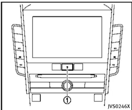
natural_image
Top-down schematic of a vehicle dashboard with labeled components (no text or symbols beyond label)TurningtheLDWsystemON/OFF
Perform the following step to turn the LDW system on or off.
- Push the MENU button ① and touch [Driver Assistance] on the lower display.
- Touch[LaneAssist].
- Touch[LaneDepartureWarning] to turn thesystemON/OFF.
LANEDEPARTUREPREVENTION (LDP)SYSTEM
PrecautionsonLDPsystem

WARNING
•The LDP system will not always steer the vehicle to keep it in the lane. It is not designed to prevent loss of control. It is the driver's responsibility to stay alert, drives safely, keep the vehicle in the traveling lane, and be in control of vehicle at all times.
•TheLDPsystemisprimarilyintendedfor useonwell-developedfreewaysorhighways.Itmaynotdetectthelanemarkers incertainroads,weatherordriving conditions.
• Using the LDP system undersome conditions of road, lanemarker or weather, or when you changangelanes without using the lane changes signal could lead to an unexpected system operation. Insuch conditions, you need to correct the vehicle's direction with your steering operation to avoid accidents.
- When the LDP system is operating, avoid excessive or sudden steering maneuvers. Otherwise, you could lose control of the vehicle.
■TheLDPsystemwillnotoperateat speedsbelowapproximately45MPH (70km/h)orifitcannotdetectlane markers.
•The LDP system may not function properly under the following conditions, and donotus the LDP system:
— Duringbadweather(rain,fog,snow, wind,etc.).
— Whendrivingonslipperyroads, suchasoniceorsnow,etc.
— Whendrivingonwindingoruneven roads.
— Whenthereisalaneclosuredueto roadrepairs.
— Whendrivinginamakeshiftlane.
— Whendrivingonroadswherethe lanewidthhistoonarrow.
— When driving with a tire that is not within normal tire conditions for example, tire wear, low tire pressure, in stalliation of spare tire, tire chains,
non-standardwheels).
— Whenthevehicleisequipped with non-originalsteeringpartsorsuspensionparts.
- If the LDP system malfunctions, it will cancel automatically. The LDP "malfunction" messagewillappear in the vehicle information display.
- If the "malfunction" message appears, pullofftheroadtoasafelocation and stopthe vehicle. Turntheengineoff and restartthe engine. If the "malfunction" message continues to appear, have the LDP system checked by an INFINIT retailer.
- Excessivenoisewillinterferewiththe warningchimesound,andthechime maynotbeheard.
The function of the LDP system (warning and steering control assist) may or may not operate properly under the following conditions:
- Onroadswheretherearemultiple parallellanemarkers;lanemarkers that are faded or not painted clearly; yellowpaintedlanemarkers;non-standardlanemarkers;lanemarkerscov
eredwithwater,dirt,snow,etc.
- Onroadswherediscontinuedlane markersarestilldetectable.
●Onroadswheretherearesharpcurves.
- On road where there are sharply contrasting objects, such as shadows, snow, water, wheelruts, seams or lines remaining after road repairs. (The LDP system could detect these items as landmarks.)
- Onroadswherethetravelinglane mergesorseparates.
- When the vehicle's traveling direction does not align with the lanemarker.
- Whentravelingclosetothevehiclein frontofyou,whichobstructsthelane cameraunitdetectionrange.
- Whenrain, snowordirtadheresto the windshieldinfrontofthelanecamera unit.
- Whentheheadlightsarenotbrightdue todirtonthelensoriftheaimingisnot adjustedproperly.
- When strong light enter the helane camera unit. (Forexample, the light directly shines on the front of the vehicle at sunrise or sunset.)
- Whenasuddenchangeinbrightness occurs.(Forexample,whenthevehicle entersorexitsatunnelorundera bridge.)

Driverassistsystemlaneindicator
LDPsystemoperation
TheLDPsystemprovidesalanedeparture warningandsteeringcontrolassistance whenthevehicleisdrivenatspeedsof approximately45MPH(70km/h)and above. Whenthevehicleapproacheseither theleftfortherightsideofthetraveling lane,awamingchimewillsoundandthe driverassistsystemlaneindicator(orange) willblinktoaertthedriver.Then,theLDP systemwillauticallyapplythesteeringforashortperiodoftimetohelpassist thedriverotoreturnthevehicletothecenter ofthetravelinglane.
5-34Startinganddriving
The warning and assist functions will stop when the vehicler return to a position inside of the melanemarker.

natural_image
Technical line drawing of a mechanical component with an arrow pointing to a circular feature (no text or symbols)Dynamicdriverassistanceswitch
The LDPsystemturnsonwhenthedynamic driverassistanceswitchonthesteering wheelispushedwhenthe[LaneDeparture Prevention]isenabledinthesettingsmenu onthelowerdisplay. Thdriverassist systemlaneindicator(green)illuminatesin thevehicleinformationdisplaywhenthe LDPsystemisturnedon.

natural_image
Top-down schematic of a vehicle dashboard with no visible text or symbolsHowtoenable/disabletheLDP system
Performthefollowingstepstoenableor disabletheLDPsystem.
- Push the MENU button ① and touch [Driver Assistance] on the lower display.
2.Touch[LaneAssist].
- Touch[LaneDeparturePrevention] to enableordisablethesystem.

Startinganddriving5-35
Automaticdeactivation
ConditionA:
The warning and assist functions of the LDP system are not designed to work under the following conditions:
- When you operate the helane change signal and changethetraveling lanes in the direction of the signal. (The LDP system will be deactivated for approximately 2 seconds after the helane change signal is turned off.)
- Whenthevehiclespeedlowerstoless thanapproximately45MPH(70km/h).
- WhentheBSIsystemactivates an audiblewarningorsteeringcontrol. Aftertheaboveconditionshavefinished and thenecessaryoperatingconditionsare satisfied,thewarningandassistfunctions willresume.
ConditionB:
TheassistfunctionoftheLDPsystemisnot designedtoworkunderthefollowing conditions(warningisstillfunctional):
- When the steering wheel is turned as far as necessary for the vehicle to changelanes.
- When the accelerator pedal is depressed while the steering control assists provided.
- When the Intelligent Cruise Control (ICC) approach warning occurs.
- Whenthehazardwarningflashersare operated.
- When driving on acurve at high speed. After the above conditions have finished and then necessary operating conditions are satisfied, the LDP steering control assist function will resume.
ConditionC:
Underthefollowingconditions, abeepwill soundandtheLDPsystemwillbecanceled automatically. The "LDPcurrentlyunavailable" message will appear in the vehicle information display, and the LDP system cannot be activated:
- WhentheVDCsystem(exceptTCS function)orABSoperates.
- WhentheVDCsystemisturnedoff. - WhentheINFINITIDriveModeSelector isturnedtotheSNOWmode.
Actionto take:
When the above conditions no longer exist, push the dynamic driver assistance switch again to turn the LDP system back on.
Temporarydisabledstatusathighttemperature:
If the vehicle is parked in direct sunlight under high temperature conditions (over approximately 104°F (40°C)) and then the LDP system is turned on, the LDP system may be deactivated automatically. The "high cap temperature" message will appear in the vehicle information display.
Actiontotake:
Whentheaboveconditionsnolongerexist, pushthedynamicdriverassistanceswitch againtoturntheLDPsystembackon.
SYSTEMMAINTENANCE
The LDW/LDP system uses the same camera unit that is used by Active Lane Control, located above the insidemirror. Form maintenance of the camera, see "Lane camera unit maintenance" (P.5-29).
BLINDSPOTWARNING/BLINDSPOT INTERTENTION™/BACK-UPDCLUSION
INTERVENTION™/BACK-UPCOLLISION
INTERVENTIONSYSTEMS(itsoequipper)
Thissectioncontainstheinformation
abouttherollowingsystems
●BlindSpotWarning(BSW)system
■BlindSpotIntervention ^TM (BSI)system
●Back-upCollisionIntervention(BCI)
system
BLINDSPOTWARNING(BSW)SYSTEM/BLINDSPOTINTERVENTION™ (BSI)SYSTEM
TheBlindSpotWarning(BSW)andBlind
SpotIntervention ^TM (BSI)systemscanhelp
alertthedriverofothervehiclesin
adjacentlaneswhenchanginglanes.
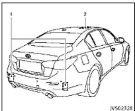
natural_image
Line drawing of a sedan car front view with numbered components (no text or symbols)TheBSWsystemusesradarsensors
installedneartherearbumpertodetect
othervehiclesinanadjacentlane.in
additiontotheradarsensors,theBSI
systemusesacamera ② installedbehind
thewindshieldtomonitorthelanemarkers
ofyourtravelinglane.
①
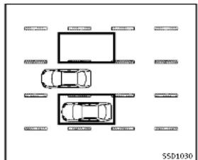
natural_image
Top-down diagram of a multi-lane road with cars and parking areas (no text or symbols)Detectionzone
Theradarsensorscandetectvehicleson
eithersideofyourvehiclewithinthe
detectionzoneshownasillustrated. This
detectionzonestartsfromtheoutside
mirrorofyourvehicleandextendsapprox
mately10ft(3m)behindtherearbumper,
andapproximately10ft(3m)sideways.

Information Provided by:
DEALER
兹:卢声云已直接信
Startinganddriving5-37

natural_image
Diagram of a car interior showing a gridded grille and handle, with no visible text or symbolsSideindicatorlight
TheBSWSystemoperatesaboveapproximately20MPH(32km/h).Iftheradar sensors detectvehiclesinthedetection zone,theside indicatorlightilluminates.If thedriverthenactivatesthetursignal, a chimewillsoundtwice andtheside indicatorlightwillflash. TheBSIsystemoperatesaboveapproximately37MPH(60km/h).Ifthesystem detectsvehicleinthedetectionzoneand yourvehicleisapproachingthelane marker,theBSIsystemprovidesanaudiblewarning(threetimes),flashestheside indicatorlightandslightlyappliesthe steeringforashortperiodoftimetohelp
5-38 Starting and driving
returnthevehiclebacktothetraveling lane.TheBSIsystemprovidesanaudible warningandturnsonorflashestheside indicatorlighteveniftheBSWsystemis off.
WARNING
■TheBSWandBSIsystemsarenota replacementforproperdrivingprocedure andarenotdesignedtopreventcontact withvehiclesorobjects.Whenchanging lanes,alwaysusethesideandrear mirrorsandturnandlookinthedirectionyouwillmovetoensureitissafeto changelanes.Neverrelysoletyonthe BSWorBSIsystem.
•UsingtheBSIsystemundersomeroad, lanemarkerorweatherconditionscould leadtoimpropersystemoperation.Alwaysrelyonyourownsteeringand brakingoperationtoavoidaccidents.
■TheBSWandBSIsystemsmaynot provideawarningorsteeringcontrol for vehicles that pass through the detection zone quickly.

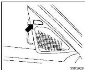
natural_image
Diagram of a car's front and side view showing a hand holding a textured object, with no visible text or symbols.Sideindicatorlight
BSWsystemoperation Iftheradarsensorsdetectvehiclesinthe detectionzone, thesideindicatorlight locatedinsidethevehicle(neartheoutside mirrors)illuminates. Iftheturnsignalis thenactivated, thesideindicatorlight flashesandachimesoundstwice. The sideindicatorlightcontinuestoflashuntil thedetectedvehiclesleavethedetection zone.
Thesideindicatorlightsilluminatefora fewsecondswhentheignitionswitchis placedintheONposition.
The brightnessofthesideindicatorlights isadjustedautomaticallydependingonthe brightnessoftheambientlight. Achimesousiftheradarsensorshave alreadydetectedvehicleswhenthedriver activatesetheturnsignal,Ifvehiclecomes intothedetectionzoneafterthedriver activatesetheturnsignal,thenonlytheside indicatorlightflashesandnochime sounds.(See“BSW/BSIdrivingsituations”(P.5-43).)

natural_image
Top-down line drawing of a vehicle rear view showing front, side, and top views (no text or symbols)[DriverAssistance]onthelowerdisplay.
2.Touch[BlindSpotAssist].
- Touch[SidelIndicatorBrightness] and select[Bright], [Standard] or [Dark].
Whenthebrightnesssettingischanged, thesideindicatorlightsilluminatefora fewseconds.
TurningtheBSWsystemON/OFF:
Performthefollowingstepstoturnthe BSWsystemonoroff.
- Push the MENU button ① and touch [Driver Assistance] on the lower display.
2.Touch[BlindSpotAssist].
- Touch[BlindSpotWarning]toturnthe systemON/OFF.
Settingthesideindicatorlightbrightness:
The brightness of the side indicator lights can be changed in the following steps:
1.Push the MENU button ① and quch
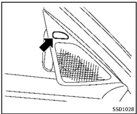
natural_image
Diagram of a car's front and side view showing a mesh grille and a directional arrow (no text or symbols)Sideindicatorlight
BSIsystemoperation
Iftheradarsensorsdetectvehiclesinthe detectionzone,thesideindicatorlight locatedinsidethevehicle(neartheoutside mirrors)illuminates.Ifyourvehicleis approachingalanemarker,theside indicatorlightflashesandanaudible warningwillsoundthreetimes.Thenthe systemappliestheeringforashort periodoftimetohelpreturnthevehicle backtothecenterofthelane.BSloperates regardlesssofturnsignalusage.
NOTE:
- Warningandsteeringcontrolwillonly beactivatedifthesideindicatorlight isalreadyilluminatedwhenyourvehicleapproachesalanemarker.If anothervehiclecomesintothedetectionzoneafteryourvehiclehascrossedalanemarker,nowarningor steeringcontrolwillbeactivated.(See "BSW/BSIdrivingsituations"(P.5-43).)
●TheBSIsystemistypicallyactivated earlierthantheLaneDeparturePrevention(LDP)systemwhenyourvehicleisapproachingalanemarker.
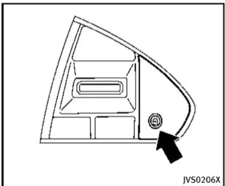
natural_image
Technical line drawing of a car interior panel with a black arrow pointing to a circular component (no text or symbols)Dynamicdriverassistanceswitch
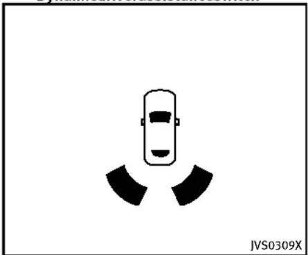
natural_image
Simple line drawing of a car with two triangular shapes below (no text or symbols)Driverassistsystemblindspotindicator

Information Provided by: DEALER
5-40 Starting and driving
TheBSIsystemturnsonwhenthedynamic driverassistanceswitchonthesteering wheelispushedwhenthe[BlindSpot Intervention]isenabledinthesettings menuonthelowerdisplay. Thedriver assistsystemblindspotindicator(green) inthevehicleinformationdisplayilluminateswhentheBSIsystemmisturnedon. TheBSIsystemprovidesanaudiblewarningandflashesthesideindicatorlight whenBSIsactivatedeveniftheBSW systemisoff.

natural_image
Top-down schematic of a vehicle dashboard with labeled components (no text or symbols beyond basic diagram)Howtoenable/disabletheBSIsystem: Performthefollowingstepstoenableor disabletheBSIsystem.
- Push the MENU button
① andtouch
[DriverAssistance]onthelowerdisplay. - Touch[BlindSpotAssist].
- Touch[BlindSpotIntervention] to enableordisablethesystem.

WARNING
- Do not use the BSI system under the following conditions because the system
maynotfunctionproperly.
— Duringbadweather(forexample, rain,fog,snow,wind,etc.)
— Whendrivingonslipperyroads, suchasoniceorsnow,etc.
— Whendrivingonwindingoruneven roads.
— Whenthereisalaneclosuredueto roadrepairs.
— Whendrivinginamakeshiftlane.
— Whendrivingonroadswherethe lanewidthhistoonarrow.
— Whendrivingwithatirethatisnot withinnormaltireconditions(for example,tirewear,lowtirepressure, installationofsparetire,tirechains, non-standardwheels).
— Whenthevehicleisequipped with non-originalbrakepartsorsuspensionparts.
- Excessivenoise(forexample, audio systemvolume, openvehiclewindow) willinterferewiththechimesound, and itmaynotbeheard.
●Theradarsensorsmaynotbeableto detectandactivateBSI/BSWwhen certainobjectsarepresentsuchas:
—Pedestrians, bicycles, animals
—Several types of vehicle less such as motorcycles
—Oncomingvehicles
—Vehiclesremaininginthedetection
zonewhenyouacceleratefroma
stop
—Avehiclemergingintoanadjacent laneataspeedapproximatelythe sameasyourvehicle
—Avehicleapproachingrapidlyfrom behind.
—Avehiclewhichyourvehicleover-takesrapidly.
See also "BSW/BSIdrivingsituations" (P.5-43) forthesituations in which the radarsensors may not be able to detect vehicle(s).
- Severeweatherorroadsprayconditionsmayreducetheabilityoftheradartodetectothervehicles.
- Theradarsensors'detectionzoneis designedbasedonastandardlane width. Whendrivinginawiderlane, the radarsensorsmaynotdetectvehicles
inanadjacentlane.Whendrivingina narrowlane,theradarsensorsmay detectvehiclesdrivingtwolanesaway.
●Theradarsensorsaredesignedto ignoremoststationaryobjects,howeverobjectssuchasguardrails,walls,foliageandparkedvehiclesmayoccasionallybedetected.Thisisanormal operatingcondition.
- Thecameramaynotdetectlanemarkersinthefollowingsituationsandthe BSIsystemmaynotoperateproperly.
—Onroadswheretherearemultiple parallellanemarkers;lanemarkers that are faded or not painted clearly; yellowpaintedlanemarkers; non-standardlanemarkers; lanemarkers covered with water, dirt, snow, etc.
—Onroadswherediscontinuedlane markersarestilldetectable.
—Onroadswheretherearesharp curves.
—Onroadswheretherearesharply contrastingobjects,suchasshadows, snow, water, wheel ruts, seams or lines remaining after road repairs. Information Provided by
—Onroadswherethetravelinglane mergesorseparates.
—Whenthevehicle'stravelingdirectiondoesnotalignwiththelane markers.
—Whentravelingclosetothevehicle infrontofyou, which obstructsthe lanecameraunitdetectionrange.
—Whenrain, snowordirtadheresto thewindshieldinfrontofalane cameraunit.
—Whentheheadlightsarenotbright duetodirton thelensorifaimingis notadjustedproperly.
—When strong light tentersalane camera unit. (Forexample, light directly shines on the front of the vehicle at sunrise or sunset.)
—Whenasuddenchangeinbrightnessoccurs.(Forexample,whenthe vehicleentersorexitsatunnelor underabridge.)
5-42 Starting and driving

text_image
SSD1026BSW/BSIDRIVINGSITUATIONS
Another vehicle approaching from behind
Thesideindicatorlightilluminatesifa vehicleentersthedetectionzonefrom behindinanadjacentlane.
However, if the overtaking vehicle is traveling much faster than your vehicle, the side indicator light may not illuminate before detected vehicle is beside your vehicle. Always usetheside and rear mirrors and turn and look in the direction your vehicle will mov to ensure it safe to changelanes.
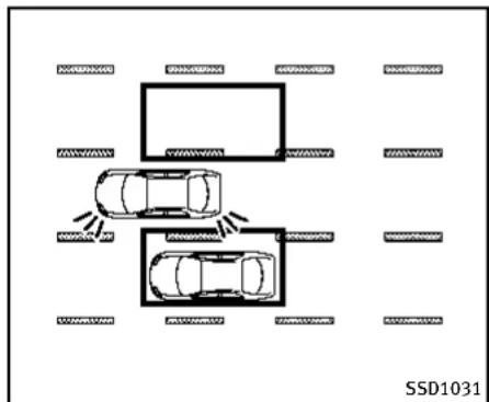
text_image
SSD1031If the driver activates the return signal, then the side indicator light flashes andachime will sound twice.
NOTE:
If the driver activates the turns signal before vehicle enter the detection zone, the side indicator light will flash but no chimewill sound when the other vehicle is detected.
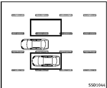
text_image
SSD1044IftheBSIsystemisonandyourvehicleis approachingalanemarker,theside indicatorlightflashesandachimewill soundthreetimes.ThentheBSIsystem slightlyappliesthesteeringtohelpreturn thevehiclebacktothecenterofthedriving lane.

Information Provided by: DEALER

text_image
SSD1032NOTE:
If you accelerate from a stop with a vehicle in the detection zone, the other vehicle may not be detected.
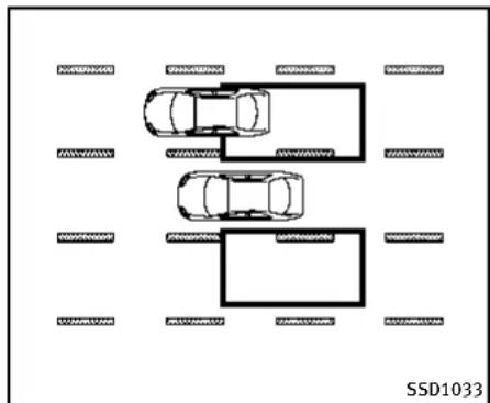
text_image
SSD1033Overtakingothervehicles
Thesideindicatorlightilluminatesify you overtakevehicleandthatvehiclestaysin the detectionzoneforapproximately3 seconds.
Theradarsensorsmaynotdetectslower movingvehiclesiftheyarepassedquickly.
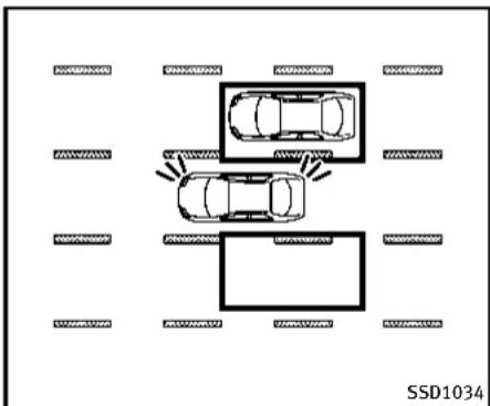
text_image
SSD1034If the driver activates the turn signal while another vehicle is in the detection zone, thentheside indicator light flashes and a chimewill sound twice.

Information Provided by
DEALER
5-44 Starting and driving

text_image
SSD1093IftheBSIsystemisonandyourvehicle approachesalanemarkerwhileanother vehicleisinthedetectionzone,theside indicatorlightflashesandachimewill soundthreetimes.Then,theBSIsystem slightlyappliesthesteeringtohelpreturn thevehiclebacktothecenterofthedriving lane.

text_image
SSD1036NOTE:
Whenovertakingseveralvehiclesinarow, thevehiclesafterthefirstvehiclemaynot bedetectediftheyaretravelingclose together.

Information Provided by: DEALER
Startinganddriving5-45

text_image
SSD1037Enteringfromtheside
Thesideindicatorlightilluminatesifa vehicleentersthedetectionzonefrom eitherside.
NOTE:
Theradarsensorsmaynotdetectvehicle whichistravelingataboutthesamespeed asyourvehiclewhenitentersthedetectionzone.
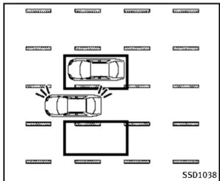
text_image
SSD1038If the driver activates the return signal, then the side indicator light flashes andachime will sound twice.
NOTE:
If the driver activates the turns signal before vehicle enter the detection zone, the side indicator light will flash but no chimewill sound when another vehicle is detected.

text_image
SSD1094IftheBSIsystemisonandyourvehicle approachesthelanemarkerwhileanother vehicleisinthedetectionzone,theside indicatorlightflashesandachimewill soundthreetimes.Then,theBSIsystem slightlyappliesthesteeringtohelpreturn thevehiclebacktothecenterofthedriving lane.

Information Provided by: DEALER
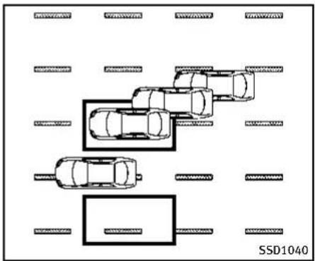
natural_image
Top-down diagram of a parking lot with multiple cars and parking areas, no text or symbols presentNOTE:
●TheBSIsystemwillnotoperateifyour vehicleisonalanemarkerwhen anothervehicleentersthedetection zone.InthiscaseonlytheBSWsystem operates.
- BSIsteeringassistwillnotoperateor willstopoperatingandonlyawarning chimewillsoundunderthefollowing conditions.
—When the accelerator pedal is depressed while steering control as sistis provided.
—Whensteeringquickly
—WhentheICC, DCA, predictiveforwardcollisionwarningorforward emergencybrakingwarningssound.
—Whenthehazardwarningflashers areoperated.
—Whendrivingonacurveatahigh speed.
BSW/BSItemporarilynotavailable
ConditionA:
●Underthefollowingconditions,theBSI systemwillbeturnedoffautomatically, abeepwillsoundandthe"currently unavailable"warningmessagewill appearinthevehicleinformationdisplay.TheBSWsystemisstillavailable, buttheBSIsystemwillnotbeavailable untiltheconditionsnolongerexist.
—WhentheVDCsystem(exceptTCS function)orABSoperates.
—WhentheVDCsystemisturnedoff.
—WhentheINFINITIDriveModeSelectoristurnedtotheSNOWmode.
Actiontotake:
Turn off the BSI system and turn it on again when the above conditions no longer exist.

ConditionB:
BSWsystem:Whenradarblockageis detected,theBSWsystemwillbedeactivatedautomatically,the"sideradarobstruction"warningmessagewillappear andthedriverassistsystemblindspot indicator(white)willblinkinthevehicle informationdisplay.
BSIsystem:Whenradarblockageis detected,theBSIsystemwillbeturned offautomatically,abeepwillsoundand the"sideradarobstruction"warningmessagewillappearinthevehicleinformation display.
TheBSWandBSIsystemsarenotavailable untiltheconditionsnolongerexist. Theradarsensorsmaybeblockedby temporaryambientconditionssuchas splashingwater,mistorfog.Theblocked conditionmayalsobecauusedbyobjects suchasice,frostordirtobstructingthe radarsensors.
Actiontotake:
Whentheaboveconditionsnolongerexist, theBSWsystemwillresumeautomatically. FortheBSIsystem,turnitonagain.Ifthe driverassistsystemblindspotindicator (white)continuestoblinkand/orthe"side
Startinganddriving5-47
radarobstruction"warningmessageappearsevenaftertheBSIsystemisturned onagain,stopthevehicleinasafelocation andturntheengineoff.Checkforand removeobjectsobscuringtheradarsensorsontherearbumper,andrestartthe engine.
ConditionC:
If the vehicle is sparked indirect sunlight under high temperature conditions (over approximately 104°F (40°C)) and then the BSIsystemisturned on, the BSIsystem may be deactivated automatically. The "highcabintemperature" warning message will appear in the vehicle information display.
Actiontotake:
Whentheaboveconditionsnolongerexist, pushthedynamicdriverassistanceswitch againtoturntheBSIsystembackon.
BSW/BSImalfunction
WhentheBSW/BSIsystemsmalfunction, theywillbeturnedoffautomatically, a beepwillsound, theandthesystem "malfunction" warningmessage with the driverassistsystemblindspotindicator (orange) willappearinthevehicleinformation display.
5-48 Starting and driving
Actiontotake:
Stopthevehicleinasafelocation, turn the engineoffandrestarttheengine.
If the system malfunction warning message with the driver assists system blind spot indicator (orange) continuestobedisplayed, have the BSW/BSI systems checked by an INFINIT retailer.
BACK-UPCOLLISIONINTERVENTION (BCI) SYSTEM
TheBack-upCollisionIntervention(BCI) system can help alert the driver of approaching vehicles or rear objects when the driver is backing out of a parking space.
WhentheshiftleverisintheR(Reverse) positionandthevehiclespeedislessthan approximately5MPH(8km/h),theBCI systemoperates.

Information Provided by: DEALER
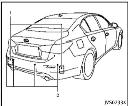
natural_image
Line drawing of a car front view with labeled parts (no text or symbols on the diagram itself)
text_image
JVS0173X
natural_image
Top-down technical drawing of a car with side-mounted sensors and a textured surface (no text or symbols)TheBCIsystemusesradarsensors ① installedonbothsidesneartherear bumpertodetectanapproachingvehicle andsonarsensors ② todetectobjectsin therear.
Theradarsensors ① detect the approaching vehicle from upto approximately 49 ft (15 m) away. Thesonarsensors ② detect arearobstacle at upto approximately 4.9 ft (1.5 m) from the bumper. Referto the illustration for approximate zone coverage areas ③.
Iftheradardetectsavehicleapproaching fromthesideorthesonardetectsclose objectsintherear,thesystemgivesvisual
andaudiblewarnings, and then applies the brake for a moment when the vehicle is moving backwards. After the automatic brake application, the driver must depress the brake pedaltomaintain brake pressure. If the driver's foot is on the accelerator pedal, the system pushes the accelerator upward before applying the brake. If you continue to press the accelerator, the system will not engage the brake.

WARNING
- TheBCIsystemisnotareplacementfor properdrivingprocedureandisnot designedtopreventcontactwithvehiclesorobjects.Whenbackingoutof parkingspace,alwaysusetheinside andoutsiderearviewmirrorsandturn andlookinthedirectionyouwillmove. NeverrelysolelyontheBCIsystem.
- Thereisalimitationtothedetection capabilityoftheradarandthesonar. UsingtheBCIsystemundersomeroad, ground, lane marker, traffic or weather conditions could lead to improper system operation. Always rely on your own
operationtoavoidaccidents.

text_image
JVS0304XUpperdisplay
BCIsystemoperation
WhentheshiftleverisplacedintheR (Reverse)position,theindicatorontheBCI systemkey ① illuminatesontheupper display.
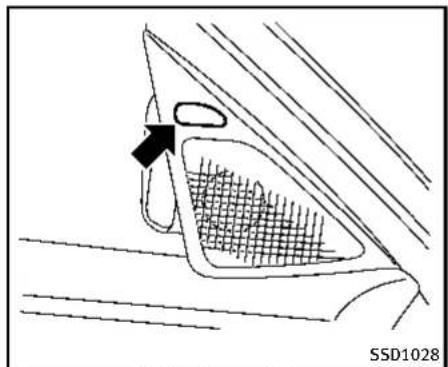
natural_image
Diagram of a car's front and side panels showing a mesh grille and a directional arrow (no text or symbols)Sideindicatorlight
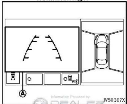
text_image
Information Provided by: JVS0307XUpper display
TheBCIsystemoperatesbydetectingthe vehiclesand/orobjectsusingeitherthe radarorsonarsensors.
Anapproachingvehiclefromtheside:
Iftheradardetectsanapproachingvehicle fromtheside,thesystemchimesasound (singlebeep),thesideindicatorlighton thesidethevehicleapproachingfrom flashesandayellowrectangularframe appearsontheupperdisplay.
A
5-50Startinganddriving
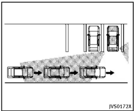
flowchart
graph TD
    A["Top View"] --> B["Left View"]
    B --> C["Right View"]
    C --> D["Bottom View"]
    D --> E["Left View"]
    style A fill:#f9f,stroke:#333
    style B fill:#ccf,stroke:#333
    style C fill:#cfc,stroke:#333
    style D fill:#fcc,stroke:#333
    style E fill:#cff,stroke:#333
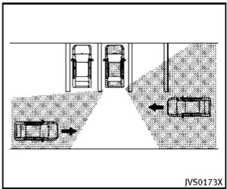
text_image
JVS0173XNOTE:
●Inthecaseofseveralvehiclesapproachinginaroworintheopposite direction,achimemaynotbeissuedto theBCIsystemafterthefirstvehicle passesthesensors.
- Whenthesonarsoundsatone, the BCI system does not chimeasound (single beep).
If the detected vehicle approaches closer and your vehicle is back to upward, the detected vehicle, the system chimes a sound (threetimes) and are rectangular frame ① appears the upper display. The system applies the brake for a moment. After the automatic brake application, the driver must depress the brake pedaltomaintain brake pressure.
Ifthedriver'sfootisontheaccelerator pedal,thesystempushestheaccelerator pedalupwardbeforeapplyingthebrake.If youcontinuetopresstheaccelerator pedal,thesystemwillnotengagethe brake.
A close object behind the vehicle:
If the sonar detects a close object behind the vehicle when your vehicle is backing up, the system chimes a sound (three
times) and red rectangular frame appear on the upper display. Thesystem appliesthebrakeforamoment. After the automatic brake application, the driver must depress the brake pedal to maintain brake pressure.
Ifthedriver'sfootisontheaccelerator pedal,thesystempushestheaccelerator pedalupwardbeforeapplyingthebrake.If youcontinuetopresstheaccelerator pedal,thesystemwillnotengagethe brake.
NOTE:
TheBCIsystemdoesnotoperateifthe objectisveryclosetothebumper.

text_image
JVS0304XUpperdisplay
TheBCIsystemisturnedofftemporarilyby touchingtheBCIsystemkey ① onthe upperdisplay.TheindicatorontheBCION keyturnsoff.
WhentheshiftleverisplacedintheR (Reverse)positionagain,theBCIsystemis turnedon.
TheBCIsystemautomaticallyturnson everytimetheengineisstarted.
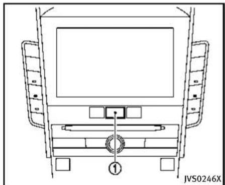
natural_image
Top-down schematic of a vehicle front view showing dashboard, steering wheel, and seat (no text or symbols)TurningtheBCIsystemON/OFF
Perform the following stepstoturning the BCIsystemonoroff.
1.PushtheMENUbutton ① andtouch [Settings]onthelowerdisplay.
2. Touch [Camera/Sonar].
3. Touch[Back-upCollisionIntervention] toturnthesystemON/OFF.
When the BCI system is mostly missed by touching [Back-up Collision Intervention], the BCI system does not turn on automatically by the following operations:
- When the shift lever is placed in the R
(Reverse)position
- Whentheengineisrestarted
5-52 Starting and driving
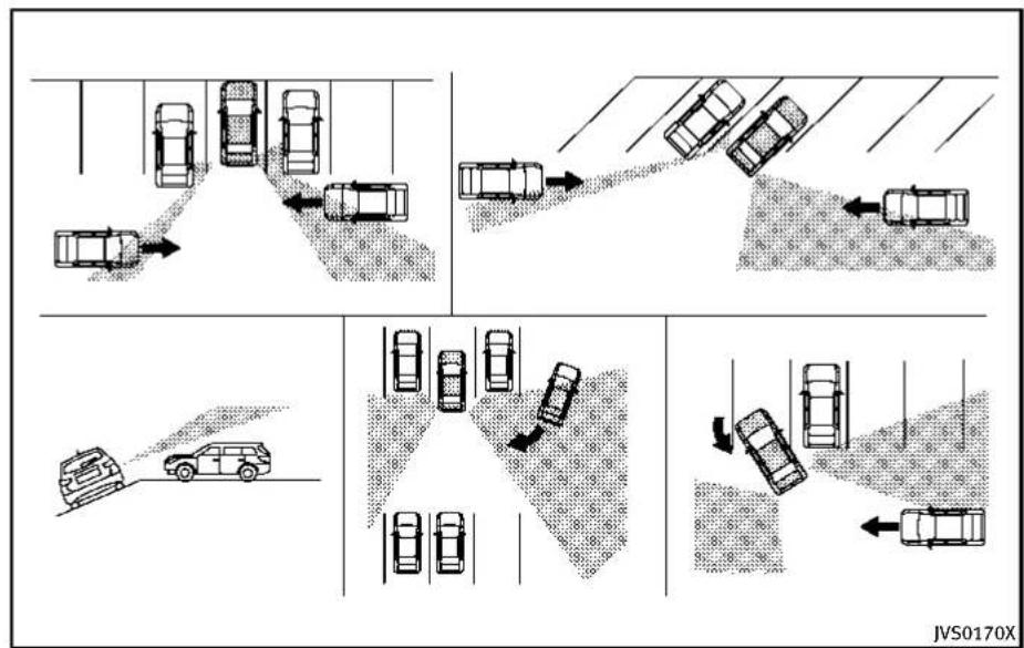
flowchart
graph TD
    A["Top Section: Car Lane with Trajectory"] --> B["Top Section: Car Road with Collision"]
    B --> C["Bottom Section: Car Road with Collision"]
    C --> D["Bottom Section: Car Road with Collision"]
    D --> E["Bottom Section: Car Road with Collision"]
    E --> F["Bottom Section: Car Road with Collision"]
    F --> G["Bottom Section: Car Road with Collision"]
    G --> H["Bottom Section: Car Road with Collision"]
    H --> I["Bottom Section: Car Road with Collision"]
    I --> J["Bottom Section: Car Road with Collision"]
    J --> K["Bottom Section: Car Road with Collision"]
    K --> L["Bottom Section: Car Road with Collision"]
    L --> M["Bottom Section: Car Road with Collision"]
    M --> N["Bottom Section: Car Road with Collision"]
    N --> O["Bottom Section: Car Road with Collision"]
    O --> P["Bottom Section: Car Road with Collision"]
    P --> Q["Bottom Section: Car Road with Collision"]
    Q --> R["Bottom Section: Car Road with Collision"]
    R --> S["Bottom Section: Car Road with Collision"]
    S --> T["Bottom Section: Car Road with Collision"]
    T --> U["Bottom Section: Car Road with Collision"]
    U --> V["Bottom Section: Car Road with Collision"]
    V --> W["Bottom Section: Car Road with Collision"]
    W --> X["Bottom Section: Car Road with Collision"]
PrecautionsonBCIsystem

WARNING
- Theradarsensorsmaynotbeableto detectcertainobjectssuchas:
— Pedestrians, bicyclesoranimals
— Avehiclethatispassingatspeeds greater than approximately 15 MPH (24 km/h)
• The radar sensors may not detect
approaching vehicles incertainsituations.
— Whenthevehicleparkednexttoyou obstructsthebeamoftheradar sensor.
— Whenthevehicleisparkedinan angledparkingspace.
— Whenthevehicleisparkedon inclinedground.
— Whenavehicleturnsintoorbacks upintoyourvehicle'saisle.
— Whentheangleformedbyyour vehicleandapproachingvehicleis small.
- Severeweatherorroadsprayconditions mayreducetheabilityoftheradarto detectothervehicles.
•Thesonarsensormaynotdetect:
— Smallormovingobjects
— Wedge-shapedobjects
— Objectclosetothebumper(less thanapproximately1ft(30cm))
— Thinobjectssuchasrope,wireand chain,etc.
●ThebrakeengagementbytheBCI systemisnotaseffectiveonaslopeas itisonflatground.Whenonasteep slopethesystemmaynotfunction properly.
- DonotusetheBCIsystemsunderthe followingconditionsbecausethesystem maynotfunctionproperly.
— Whendrivingwithatirethatisnot withinnormaltireconditions(for example,tirewear,lowtirepressure, installationofsparetire,tirechains, non-standardwheels).
— Whenthevehicleisequipped with non-originalbrakepartsorsuspensionparts.
- Excessivenoise(forexample, audio systemvolume, openvehiclewindow) willinterferewiththechimesound, and itmaynotbeheard.
BCItemporarilynotavailable
When the following message appears in the vehicle information display, achime will sound and the BCIsystem will be turned off automatically.
5-54 Starting and driving
- "UnavailableHighAcceleratorTemp.": Whentheacceleratorpedalactuator detectsthattheinternalmotortemperatureishigh.
Actiontotake:
TurnontheBCIsystemagainwhenthe aboveconditionnolongerexists.
- "UnavailableSideRadarObstruction":
Whensideradarblockageisdetected. Actiontotake:
If the warning message appears, park the vehicle in as a safe place, turn the engine off. Check for and remove objects obscuring theradarsensors on therear bumper, and restart the engine. If the BSWor BSI system operates normally, the BCI system will also operate normally. (See "BSW/BSI temporarily not available" (P. 5-47).)
BCImalfunction
When the BCIsystem malfunctions, it will be turned off automatically, abeepwill sound and BCIsystem "malfunction" warning message will appear in the vehicle information display.
Stop the vehicle in a safe location, turn the engine off and restart the engine. If the warning message continues to appear,
havethesystemcheckedbyanINFINITI retailer.

text_image
1 2 JVS0232XSYSTEMMAINTENANCE
●Thetworadarsensorunits ① forthe BSW,BSlandBCIsystemsarelocated neartherearbumper.Alwayskeepthe areaneartheradarsensorsclean.Do notattachstickers(includingtransparentmaterial),installaccessoriesor applyadditionalpaintneartheradar sensors.Donotstrikeordamagethe areaaroundtheradarsensors.Consult anINFINITretaileriftheareaaround theradarsensorsisdamagedduetoa collision.
●TheBSIsystemusesthesamecamera
② thatisusedbyActiveLaneControl,
locatedabovetheinsidemirror. Formaintenanceofthecamera,see“Lane cameraunitmaintenance”(P.5-29).
Radiofrequencystatement ForUSA
Thisdevicecomplieswithpart15ofthe FCCRules.
Operationissubjecttothefollowingtwo conditions:(1)Thisdevicemaynotcause harmfulinterference,and(2)thisdevice mustacceptanyinterferencereceived, includinginterferencethatmaycause undesiredoperation.
NOTE:
Themanufacturerisnotresponsiblefor anyradioorTVinterferencecausedby unauthorizedmodificationstothisequipment.Suchmodificationscouldvoidthe user'sauthoritytooperatetheequipment.
ForCanada
This device complies with Industry Canada Standard RSS-310.
Operation is subject to the following two conditions: (1) This device may not cause harmful interference, and (2) this device must accept any interference received,
includinginterferencethatmaycause undesiredoperation.
Frequency of operation: 24.05GHz—24.25GHz
FieldStrength: Notgreaterthan2.5V/m peak(0.25V/maverage)atadistanceof3 m
CRUISECONTROL(ifsoequipped)
PRECAUTIONSONCRUISECONTROL
- If the cruise control system malfunction, it will cancel automatically. The cruise indicator (green) in the vehicle information display will then blink to warmth driver.
- If the engine coolant temperature becomes excessively high, the cruise control system will be canceled automatically.
- Ifthecruise indicator(green)blinks, turnthecruise control MAIN switchchoff and havethesystem checked by your INFINIT retailer.
- Thecruiseindicator(green)maysometimesblinkwhenthecruisecontrol MAINswitchisturnedONwhilepushingtheSET/COAST(-),RESUME/ACCELERATE(+)orCANCELswitch.Toproperly setthecruisecontrolsystem,perform thestepsbelowintheorderindicated.

WARNING
Donotusethecruisecontrolwhendriving underthefollowingconditions:
- whenitisnotpossibletokeepthe vehicleatetspeed
5-56 Startinganddriving
•inheavytrafficorintrafficthatvariesin speed
●onwindingorhillyroads
● onslipperyroads(rain, snow, ice, etc.)
•inverywindyareas
Doingsocouldcausealossofvehicle controlandresultinanaccident.

text_image
CANCEL RES+ SET- ① ② ③ ④ JVS0190X- RESUME/ACCELERATE(+)switch
- SET/COAST(-)switch
- CANCELswitch
- MAIN(ON-OFF)switch

Information Provided by: DEALER

JVS0306X
Cruiseindicator
CRUISECONTROLOPERATIONS
Thecruiseindicatorandthesetvehicle speedaredisplayedinthevehicleinformationdisplay.Thecruiseindicatorindicates thestausofthecruisecontrolsystemby thecolor.
Thecruisecontrol allows driving at aspeed between 25 to 89 MPH (40 to 144 km/h) without keeping your foot on the accelerator pedal.
Toturnonthecruisecontrol, push the MAINswitch on. The cruise indicator (white) will come on.
Tosetcruisingspeed,accelerateyour vehicletothedesiredspeed,pushthe SET/COAST(-)switchandreleaseit.(The cruiseindicator(green)willilluminates.) Takeyourfootofftheacceleratorpedal. Yourvehiclewillmaintainthesetspeed.
- Topassanothervehicle, depress the acceleratorpedal. When you release the pedal, the vehicle will return to the previously sets speed.
●The vehicle may not maintain in the speed on winding or hilly roads. If this happens, drivewithout the cruise control.
Tocancelthepresetspeed, followanyof thesemethods:
- Push the CANCEL switch.
- Tapthebrakepedal.
3.TurntheMAINswitchoff.
After any of the above operation is performed, the color of the cruise indicator will change from greentow hite.
- If you depressthebrakepedal while pushing the RESUME/ACCELERATE (+) or SET/COAST (-) switch and reset at the cruising speed, the cruise control will disengage. Turn the MAIN switch off once and then turn it on again.
- Thecruisecontrolwillautomatically cancelifthevehicleslowsmorethan 8MPH(13km/h)belowthesetspeed.
- If you movetheshiftlevertoN(Neutral) position, the cruise control will be canceled.
Toresetatafastercruisingspeed, useone of the following methods:
- Depresstheacceleratorpedal. When the vehicle attainsthedesiredspeed, pushandreleasetheSET/COAST(-) switch.
- PushandholdtheRESUME/ACCELERATE(+)switch.Whenthe vehicleattains thespeedyoudesire,releasethe switch.
- Push, then quickly releasetheRESUME/ACCELERATE(+) switch. Each time you do this, the setspeedwillincrease by about 1 MPH (1.6 km/h).
Toresetataslowercruisingspeed, use oneofthefollowingmethods:
●Lightlytapthebrakepedal. When the vehicle attains the desired speed, push the SET/COAST(-) switch and release it.
- PushandholdtheSET/COAST(-) switch.Releasetheswitchwhenthe vehicleslowsdowntothedesired
speed.
- Push, then quickly releasethe SET/ COAST(-) switch. Each time you do this, the setspeed will decrease by about 1 MPH (1.6 km/h).
Toresumethepresetspeed, pushand release the RESUME/ACCELERATE(+) switch. The vehicle will resumethelast setcruisingspeed when the vehiclespeed is over 25 MPH (40 km/h).
INTELLIGENTCRUISECONTROL(ICC) SYSTEM(ifsoequipped)
The Intelligent Cruise Control (ICC) system maintains a selected distance from the vehicle in front of you within the speed range of 0 to 90 MPH (0 to 144 km/h) up to the setspeed. The speed can be selected by the driver between 20 to 90 MPH (32 to 144 km/h).
The vehicle travels atsetspeed when the road ahead is clear.
TheICCfunctioncanbesettooneoftwo cruisecontrolmodes:
●Vehicle-to-vehicle distance control mode:
Formaintainingaselecteddistance betweenyourvehicleandthevehicle infrontofyouuptothepresetspeed.
●Conventional(fixedspeed)cruise controlmode:
Forcruisingatapresetspeed.

WARNING
●Alwaysdrivecarefullyandattentively whenusingeithercruisecontrolmode. Read and understand the Owner's Manual thoroughly before using the cruise control. To avoid serious injury or death, do not rely on the system to prevent
accidentsortocontrolthevehicle's speedinemergencysituations.Donot usecruisecontrolexceptinappropriate roadandtrafficconditions.
●Intheconventional(fixedspeed)cruise controlmode,awarningchimewillnot soundtowarnyouifyouaretoocloseto thevehicleahead.Payspecialattention tothedistancebetweenyourvehicleand thevehicleaheadofyouoracollision couldoccur.

text_image
① 60 MPH A
text_image
② 60 MPH A JVS0209X- Vehicle-to-vehicledistancecontrol mode
- Conventional(fixedspeed)cruisecontrolmode
PushtheMAINswitch ① tochoosethe cruisecontrolmodebetweenthevehicle-to-vehicledistancecontrolmode ① and theconventional(fixedspeed)cruisecontrolmode ②.
Tochoosethevehicle-to-vehicledistance controlmode ①,quicklypushandrelease theMAINswitch Ⓐ.Tochoosethe conventional(fixedspeed)cruisecontrol mode ②,pushandholdtheMAINswitch Ⓐ forlongerthanapproximately1.5
seconds.
Onceacontrolmodeisactivated, it cannot be changed to the other cruise control mode. To changethemode, push the MAIN switch on cetoturn the system off. Then push the MAIN switch againtoturn the system back on and select the desired cruise control mode.
Alwaysconfirmthesettinginthelntelligent CruiseControl(ICC)systemdisplay. For the vehicle-to-vehicle distance control mode, see the following description. For the conventional (fixed speed) cruise control mode, see "Conventional (fixed speed)
cruisecontrolmode"(P.5-74).
SELECTINGTHEVEHICLE-TO-VEHICLEDISTANCECONTROLMODE
Tochoosethevehicle-to-vehicledistance controlmode ①, quicklypushandrelease theMAINswitch Ⓐ.
VEHICLE-TO-VEHICLEDISTANCE CONTROLMODE
Inthevehicle-to-vehicledistancecontrol mode,theIntelligentCruiseControl(ICC) systemautomaticallymaintainsaselected distancefromthevehicletravelinginfront ofyouaccordingtothatvehicle'sspeed (uptothesetspeed),oratthesetspeed whentheroadaheadisclear.
With ICC, the driver can maintain the same speed as other vehicles without the constant need to adjust these speed as you would with an normal cruise control system.

natural_image
Line drawing of a car front view with labeled section A, no text or symbols presentPRECAUTIONSONVEHICLE-TO-VE- HICLEDISTANCECONTROLMODE
Thesystemisintendedtoenhancethe operationofthevehiclewhenfollowinga vehicletravelinginthesamelaneand direction.
Ifthedistancesensor Ⓐ detectsaslower movingvehicleahead,thesystemwill reducethevehiclespeedsothatyour vehiclefollowsthevehicleinfrontatthe selecteddistance.
Thesystemautomaticallycontrolsthe throttleandappliesthebrakes(upto approximately40%ofvehiclebraking
power)ifnecessary.
The detection range of the sensoris approximately 650ft (200m) ahead.

WARNING
- This system is only an aid to assist the driver and not a collision warning or avoidance device. It is the driver's responsibility to stay alert, drives safely and be in control of the vehicle at all times.
- Thesystemisprimarilyintendedforuse onstraight,dry,openroadswithlight traffic.Itisnotadvisabletousethe systemincitytrafficorcongestedareas.
- Thissystemwillnotadaptautomatically toroadconditions. Thissystemshould beusedinevenlyflowingtraffic. Donot usethesystemonroadswithsharp curves, oronicyroads, inheavyrainor infog.
Thedistancesensorwillnotdetectunder mostcon ditions:
• Stationary and slow moving vehicles
- Pedestrians or objects in the roadway
- Oncoming vehicles in the same lane
- Motorcycles traveling offset in the travel lane

WARNING
- Asthereisaperformancelimittothe distancecontrolfunction,neverrely solelyontheIntelligentCruiseControl (ICC)system.Thisssystemdoesnot correctcareless,inattentiveorabsent-mindeddriving,overcomepoorvisibility in rain, fog, or other bad weather. Deceleratethe vehicle speed bydepressing the brake pedal, depending on the distancetothevehicleaheadandthe surroundingcircumstancesinorderto maintainasafedistancebetweenvehicles.
- Ifthevehicleaheadcomestoastop,the vehicledeceleratestoastandstillwithin thelimitationsofthesystem.The systemwillcancelonceitjudgesthat thevehiclehascometoastandstill and soundawarningchime. Topreventthe vehiclefrommoving,thedrivermust depressthe brakepedal.
• The system may not detect the vehicle in
frontofyouincertainroadorweather conditions.Toavoidaccidents,neveruse theICCsystemunderthefollowing conditions:
— Onroadswherethetrafficisheavy ortherearesharpcurves
— Onslipperyroadsurfacessuchas oniceorsnow,etc.
— Duringbadweather(rain,fog,snow, etc.)
— Whenrain, snowordirtadhereto thesystemsensor
— Onsteepdownhillroads(thevehiclemaygobeyondthesetvehicle speedandfrequentbrakingmay resultinoverheatingthebrakes)
— Onrepeateduphillanddownhill roads
— Whentrafficconditionsmakeit difficulttokeepapoperdistance betweenvehiclesbecauseoffrequentaccelerationordeceleration
●Insomeroadortrafficconditions, a vehicleorobjectcanunexpectedlycome intothesensordetectionzoneandcause automaticbraking.Youmayneedto
controlthedistancefromothervehicles usingtheacceleratorpedal.Alwaysstay alertandavoidusingtheICCsystem whenitisnotrecommendedinthis section.
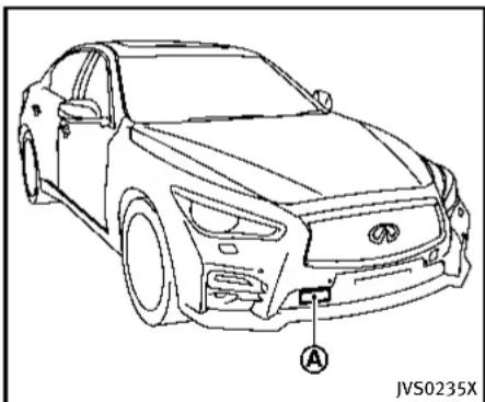
natural_image
Line drawing of a sedan car with labeled component A, no text or symbols presentAlwayspayattentiontotheoperationof thevehicleandbereadytomanually controltheproperfollowingdistance.The vehicle-to-vehicledistancecontrolmode of theIntelligentCruiseControl(ICC)system maynotbeabletomaintaintheselected distancebetweenvehicles(followingdistance)orselectedvehiclespeedunder somecircumstances.
The vehicle-to-vehicledistancecontrol modeusesasensor located behind the lower grille of the front bumperto

Information Provided by: DEALER
detectvehiclestravelingahead. Thesensor generally detectsthesignalsreturned from the vehicleahead. Therefore, if the sensor cannot detect thereflection from the vehicleahead, the ICCsystemmay not maintain these selected distance.
The following aresome conditions in which the sensor cannot detect the signals:
- Whenthesnoworroadsprayfrom travelingvehiclesreducesthesensor's visibility
- Whenexcessivelyheavybaggageis loadedintherearseatorthetrunkof yourvehicle
TheICCsystemisdesignedtoautomaticallycheckthesensor'soperationwithinthelimitationsofthesystem.Whenthesensorareaofthefrontbumperiscoveredwithdirtorisobstructed,thesystemwillautomaticallybecanceled.Ifthesensorareaiscoveredwithice,attransparentortranslucentvinylbag,etc.,theICCsystemmaynotdetectthem.Intheseinstances,thevehicle-to-vehicledistancecontrolmodemaynotcancelandmaynotbeabletomaintaintheselectedfollowingdistancefromthevehicleahead.Besuretocheckandcleanthesensorarearegularly.
Thevehicle-to-vehicledistancecontrol modeisdesignedtomaintainaselected distanceandreducethespeedtomatch theslowervehicleahead;thesystemwill deceleratethevehcleasnecessaryandif thevehicleaheadcomestoastop,the vehicledeceleratestoastandstill.However,thelCCsystemcanonlyapplyupto approximately40%ofthevehiclestotal brakingpower.Thissystemshouldonlybe usedwhentrafficconditionsallowvehicle speedstoremainfairlyconstantorwhen vehiclespeedschangegradually.Ifa vehiclemovesintothetravelinglaneahead orifavehicletravelingaheadrapidly decelerates,thedistancebetweenvehicles maybeocloserbecausethelCCsystem cannotdeceleratethevehiclequicklyenough.Ifthisoccurs,thelCCsystemwill soundawarningchimeandblinkthe systemdisplaytonotifythedrivertotake necessaryaction.
Thesystemwillcancelandawarning chimewillsoundifthespeedisbelow approximately15MPH(24km/h)anda vehicle is not detected ahead. The system will also disengage when the vehicle goes above the maximum set speed.
See "Approach warning" (P.5-71).
The following items are controlled in the vehicle-to-vehicledistance control mode:
- When there are an overvehicle traveling ahead, the vehicle-to-vehicled distance control modem maintain sthespeed set by the driver. Thesetspeed range is between approximately 20 and 90 MPH (32 and 144 km/h).
- Whenthereisavehicletravelingahead, thevehicle-to-vehicledistancecontrol modeadjuststhespeedtomaintainthe distance,selectedbydriver,fromthe vehicleahead.Theadjustingspeed rangeisuptothesetspeed.Ifthe vehicleaheadcomestoastop,the vehicledeceleratestoastandstillwithinthelimitationsofthesystem.The systemwillcancelonceitjudgesa standstillwithawarningchime.
- When the vehicle traveling ahead has moved out from its lane of travel, the vehicle-to-vehicle distance control mode accelerates and maintains vehicles speed up to the sets speed.
TheICCsystemdoesnotcontrolvehicle speedorwarnyouwhenyouapproach stationaryandslowmovingvehicles.You mustpayattentiontovehicleoperationto maintainproperdistancefromvehicles
aheadwhenapproachingtollgatesor trafficcongestion.

text_image
SSD0252Thedetectionzoneoftheradarsensoris limited.Avehicleaheadmustbeinthe detectionzoneforthevehicle-to-vehicle distancedetectionmodetomaintainthe selecteddistancefromthevehicleahead.
Avehicleaheadmaymoveoutsideofthe detectionzoneduetoitspositionwithin thesamelaneoftravel.Motorcyclesmay notbedetectedinthesamelaneaheadif theyaretravelingoffsetfromthecenterline ofthelane.Avehiclethatisenteringthe lane ahead may not be detected until the vehicle has completely moved into the lane. If this occurs, the ICC system may warn you by blinking the system indicator
andsoundingthechime. Thedrivermay havetomanuallycontroltheproper distanceawayfromvehicletraveling ahead.

natural_image
Diagram showing multiple cars on curved road with a shaded triangular area, no text or symbols presentWhendrivingonsomeroads,suchas winding,hilly,curved,narrowroads,or roadswhichareunderconstruction,the radarsensormaydetectvehiclesina differentlane,ormaytemporarilylynot detectvehicletravelingahead.Thismay causethelCCsystemtodecelerateor acceleratethevehicle.
The detection of vehicles may also be affected by vehicle operation (steering maneuver or traveling position in the lane, etc.) or vehicle condition. If this occurs, the ICC system may warn you by blinking the system indicator and sounding the chime unexpectedly. You will have to manually
control the proper distance away from the vehicle traveling ahead.

Information Provided by: DEALER
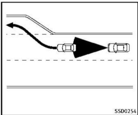
flowchart
graph TD
    A["Top Road"] --> B["Curved Arrow"]
    B --> C["Left Car"]
    C --> D["Right Car"]
    style A fill:#f9f,stroke:#333
    style D fill:#f9f,stroke:#333
    note right of C SSD0254
Whendrivingonthefreewayatasetspeed andapproachingaslowertravelingvehicle ahead, theICCwilladjustthespeedto maintainthedistance, selectedbythe driver, fromthevehicleahead. Ifthe vehicleaheadchangeslanesorexitsthe freeway, theICCsystemwillaccelerateand maintainthespeeduptothesetspeed. Payattentiontothedrivingoperationto maintaincontrolofthevehicleasit acceleratestothesetspeed.
The vehicle may not maintain the sets speed on winding or hilly roads. If this occurs, you will have to manually control the vehicles speed.
5-64 Startinganddriving
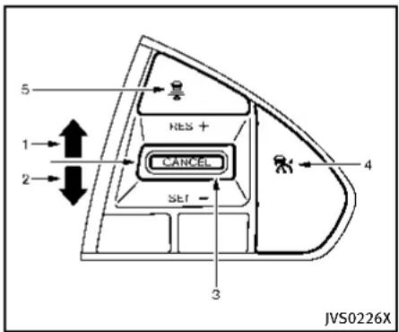
text_image
5 RES + 1 2 CANCEL SET - 3 4 JVS0226XICCswitch
ThesystemisoperatedbyaMAINswitch and four control switches, all mounted on the steering wheel.
- RESUME/ACCELERATE(+) switch:
Resumessetspeedorincreasespeed incrementally.
2.SET/COAST(-)switch:
Setsdesiredcruisespeed, reduces speedincrementally.
3.CANCELswitch:
Deactivatesthesystemwithouterasing thesetspeed.
4.MAINswitch:
Masterswitchtoactivatethesystem
5.DISTANCEswitch:
Changesthevehicle's following distance:
- Long
- Middle
- Short

Information Provided by: DEALER
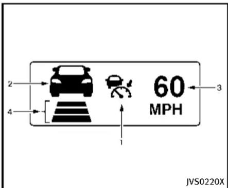
text_image
2 4 60 MPH 1 3 JVS0220XICCsystemdisplayandindicators Thedisplayislocatedbetweenthespeed- ometerandtachometer.
-
This indicator indicates the ICC system status depending on acolor.
-
IntelligentCruiseControlsystemON indicator(white): Indicate that the MAIN switch is ON.
- IntelligentCruiseControlsystemset indicator(green): Indicatesthatcruisingspeedisset
- IntelligentCruiseControlsystem warning(orange): Indicatesthatifthereisamalfunc-
Startinganddriving5-65
tionintheICCsystem.
- Vehicleaheaddetection indicator: Indicates whether it detects a vehicle in front of you.
- Set vehiclespeed indicator: Indicate the set vehiclespeed. For Canadian models, these speed is displayed in km/h.
- Setdistanceindicator: Displaystheselecteddistancebetween vehiclesetwiththeDISTANCEswitch.

text_image
MPH JVS0212XOperatingvehicle-to-vehicledistancecontrolmode
Toturnonthecruisecontrol, quickly push and releas the MAIN switch Ⓐ on. The Intelligent Cruise Control (ICC) system ON indicator (white), set distance indicator and set vehicles speed indicator come on and in a stand by state for setting.

text_image
60 MPH JVS0213XTosetcruisingspeed,accelerateyour vehicletothedesiredspeed,pushthe SET/COAST(-)switchandreleaseit.(The ICCsystemsetindicator(green),vehicle aheaddetectionindicator,setdistance indicatorandsetvehiclespeedindicator comeon.)Takeyourfootofftheaccelerator pedal.Yourvehiclewillmaintaintheset speed.

text_image
MPH JVS0214XWhen the SET/COAST(-) switch is pushed under the following conditions, the system cannot be set and the CC indicators will blink for approximately 2 seconds:
- Whentravelingbelow20MPH(32 km/h)andthevehicleaheadisnot detected
- WhentheshiftleverisnotintheD (Drive)ormanualshiftmode
●Whentheparkingbrakeisapplied - Whenthebrakesareoperatedbythe driver
WhentheSET/COAST(-)switchispushed underthefollowingconditions,thesystem cannotbeset.
A warningchimewillsoundandthe "currentlyunavailable" warningmessage appearsinthevehicleinformationdisplay.
- When the INFINITIDrive Mode Selector is turned to the SNOWmode (Tousethe ICCsystem, turn the INFINITIDrive ModeSelectortoamode other than the SNOWmode, push the MAIN switch to turn off the ICCandreset the ICC switch bypassing the MAIN switch again.) Fordetails about the INFINITIDrive Mode Selector, see "INFINITIDrive ModeSelector" (P. 5-21).
- WhentheVDCsystemisoff(Tousethe ICCsystem,turnontheVDCsystem. PushtheMAINswitchtoturnofftheICC systemandresettheICCswitchby pushingtheMAINswitchagain.) FordetailsabouttheVDCsystem,see "VehicleDynamicControl(VDC)system"(P.5-108).
- WhenABSorVDC(includingthetrac- tioncontrolsystem)isoperating
- When a wheel is slipping (To use the ICC system, make sure the wheels are no longer slipping.)

①
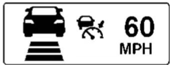
text_image
60 MPH②
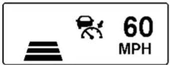
text_image
60 MPHJVS0210X
- Systemsetdisplaywithvehicleahead
- Systemsetdisplaywithoutvehicle ahead
Systemoperation

WARNING
Normallywhencontrollingthedistancetoa vehicleahead, thissystemautomatically acceleratesordeceleratesyourvehicle accordingtothespeedofthevehicleahead. Depresstheacceleratorortoproperlyaccelerateyourvehiclewhenaccelerationis requiredforalanechange.Depressthe
brakepedalwhendecelerationisrequiredto maintainasafedistancetothevehicle aheadduetoitssuddenbrakingorifa vehiclecutsin.Alwaysstayalertwhen usingtheICCsystem.
The driversetsthedesiredvehiclespeed basedontheroadconditions.TheICC systemmaintainsthesetvehiclespeed, similartostandardcruisecontrol,aslong as no vehicle is detected in the lane ahead.
The ICC system displays the set speed.

DEALER
Vehicledetectedahead:
When vehicle is detected in the lane ahead, the CC system decelerates the vehicle by controlling the throttle and applying the brake stomatch the speed of as low vehicle ahead. The system then controls the vehicles speed based on the speed of the vehicle ahead to maintain the driver selected distance.
Thestoplightsofthevehiclecomeon whenbrakingisperformedbytheICC system.
Whenthebrakeoperates,anoisemaybe heard. This is not a malfunction.
Whenavehicleaheadisdetected, the vehicleaheaddetectionindicatorcomes on. The ICCsystemwillalsodisplaytheset speedandselecteddistance.
Vehicleaheadnotdetected:
When vehicle is nolonger detected ahead, the CC system gradually accelerates your vehicle to resumethepreviously set vehicles speed. The CC system then maintains the sets speed.
When a vehicle is nolonger detected the vehicle ahead detection indicator turn soff. If a vehicle ahead appears during acceleration to the set vehicles speed or any time
5-68 Starting and driving
theICCsystemisinoperation,thesystem controlsthedistancetothatvehicle. Whenavehicleisnolongerdetectedunder approximately15MPH(24km/h),the systemwillbecanceled.
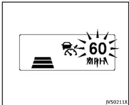
text_image
60 MHz JVS0211XWhenpassinganothervehicle,theset speedindicatorwillflashwhenthevehicle speedexceedsthesetspeed.Thevehicle detectindicatorwillturnoffwhenthearea aheadofthevehicleisopen.Whenthe pedalisreleased,thevehiclewillreturnto thepreviouslysetspeed.
Even though your vehicles speedisset in the ICC system, you can depress the accelerator pedal when it is necessary to accelerate your vehicler rapidly.

Information Provided by: DEALER
Howtochangethesetvehicle speed
Tocancelthepresetspeed, useanyof thesemethods:
●PushtheCANCELswitch.Thesetvehicle speedindicatorwillgoout.
●Tapthebrakepedal. Thesetvehicle speedindicatorwillgoout.
- TurntheMAINswitchoff. Both the Intelligent Cruise Control system set indicator(green) and set vehiclespeed indicator will go out.
Toresetatafaster cruisingspeed, useone of the following methods:
- Depresstheacceleratorpedal. When the vehicle attainsthedesiredspeed, pushandreleasetheSET/COAST(-) switch.
- PushandholdtheRESUME/ACCELERATE(+)switch.Thesetvehiclespeed willincreasebyapproximately5MPH (5km/hforCanada).
- Push, then quickly releasethe RESUME/ACCELERATE(+) switch. Each time you do this, the setspeed will increase by approximately 1 MPH (1 km/h for Canada).
Toresetataslowercruisingspeed, use oneofthefollowingmethods:
●Lightlytapthebrakepedal. Whenthe vehicleattainsthedesiredspeed, push theSET/COAST(-)switchandreleaseit.
- PushandholdtheSET/COAST(-) switch. Thesetvehiclespeedwill decreasebyapproximately5MPH(5 km/hforCanada).
- Push, then quickly releasetheSET/ COAST(-)switch. Each time you do this, the setspeed will decrease by approximately 1 MPH (1 km/h for Canada).
Toresumethepresetspeed, pushand release the RESUME/ACCELERATE(+) switch. The vehicle will resumethelast setcruisingspeed when the vehiclespeed is over 20 MPH (32 km/h).
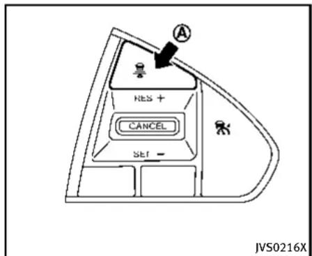
text_image
A RES + CANCEL SET - JVS0216XHowtochangethesetdistanceto thevehicleahead
Thedistancetothevehicleaheadcanbe selectedatanytimedependingonthe trafficconditions.
EachtimetheDISTANCEswitch pushed,thesetdistancewillchangeto long,middle,shortandbacktolongagain inthatsequence.
A is

Information Provided by: DEALER
5-70 Starting and driving
| Distance | Display | Approximate distance at 60 MPH (100 km/h) [ft (m)] |
| Long | 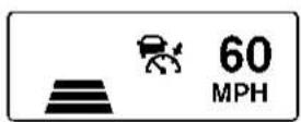 | 200 (60) |
| Middle | 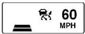 | 150 (45) |
| Short |  | 90 (30) |
JVS0250M
- Thedistancetothevehicleaheadwill changeaccordingtothevehiclespeed. Thehigherthevehiclespeed,the longerthedistance.
- If the engine is stopped, the set distance becomes "long". (Each time the engine is started, the initial setting
becomes"long".)
Approachwarning
If your vehicle comes closer to the vehicle ahead due to rapid deceleration of that vehicle or if another vehicle cuts in, the system warns the driver with the chime
andICCsystemdisplay.Decelerateby depressingthebrakepedaltomaintaina safevehicledistanceif:
●Thechimesounds.
●Thevehicleaheaddetectionandset distanceindicatorblink.
Thewarningchimemaynotsoundinsome caseswhenthereisashortdistance betweenvehicles.Someexamplesare:
- Whenthevehiclesaretravelingatthe samespeedandthedistancebetween vehiclesisnotchanging
- Whenthevehicleaheadistraveling fasterandthedistancebetweenvehiclesisincreasing
- When vehicle cuts in near your vehicle
The warning chimewill not sound when:
-Yourvehicleapproachesothervehicles thatareparkedormovingslowly.
●Theacceleratorpedalisdepressed, overridingthesystem.
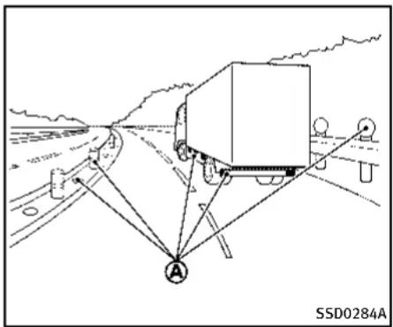
text_image
SSD0284A ANOTE:
Theapproachwarningchimemaysound andthesystemdisplaymayblinkwhen theradarsensordetectsobjectsonthe sideofthevehicle Ⓐ oronthesideofthe road Ⓐ. This may cause the CC system to decelerate or accelerates the vehicle. The radarsensormay detect these objects when the vehicle is driven on winding roads, narrow roads, hillyroads or when enteringorexiting acurve. In these cases you will have to manually control the proper distance ahead of your vehicle. Also, the sensors sensitivity can be affected by vehicle operation (steeringmaneuveror
5-72 Startinganddriving
drivingpositioninthelane)ortrafficor vehiclecondition(forexample,ifvehicle isbeingdrivenwithsomedamage).
Automaticcancellation
Achimesoundsunderthefollowingconditionsandthecontrolisautomatically canceled.
- Whenthevehicleaheadisnotdetected andyourvehicleistravelingbelowthe speedof15MPH(24km/h)
- Whenthesystemjudgesthevehicleis atstandstill
- WhentheshiftleverisnotintheD positionorManualmode
- Whentheparkingbrakeisapplied
- WhentheINFINITIDriveModeSelector isturnedtotheSNOWmode
- WhentheVDCsystemisturnedoff
- WhenABSorVDC(includingthetrac- tioncontrolsystem)operates
- Whendistance measurement becomes impaired duetoadhesion of dirtor obstruction to the sensor
- When a wheel slips

Information Provided by: DEALER
Warninganddisplay
ConditionA:
Underthefollowingconditions,theIntelligentCruiseControl(ICC)systemisautomaticallycanceled.Thechimewillsound andthe"currentlyunavailable"warning messagewillappearinthevehicleinformationdisplay.
- WhentheVDCisturnedoff
- WhentheABSorVDC(including the tractioncontrolsystem)operates
- Whenatireslips
- WhentheINFINITIDriveModeSelector isturnedtotheSNOWmode
Actiontotake:
Whentheconditionslistedaboveareno longerpresent,turntheICCsystemback ontousethesystem.
ConditionB:
Whentheradarsensorareaofthefront bumperiscoveredwithdirtorisob-structed,makingitimpossibletodetecta vehicleahead,theICCsystemisautomaticallycanceled.
Thechimewillsoundandthe"frontradar obstruction"warningmessagewillappear inthevehicleinformationdisplay.
Actiontotake:
If the warning message appears, park the vehicle in as a safe place, turn the engine off. When the adarsignal is temporarily interrupted, clean the sensor area of the front bumper and restart the engine. If the "frontradarobstruction" warning message continues to be displayed, havethel CC system checked by an INFINIT retailer.

JVS0221X
ConditionC:
WhenthelCCsystemisnotoperating properly, thechimesoundsandtheICC systemwarning(orange)willappear.
Actiontotake:
If the warning appears, park the vehicle in as afe place. Turn the engine off, restart the engine, resum driving and set the ICC system again.
Ifitisnotpossibletosethesystemorthe warning stays on, it may indicate that the ICC system is malfunctioning. Although the vehicle is still driveable under normal conditions, have the vehicle checked at an
INFINITIretailer.

natural_image
Line drawing of a car front view with labeled section A, no text or symbols presentSensormaintenance
ThesensorfortheICCsystem Ⓐ islocated behindthelowergrilleofthefrontbumper.
TokeeptheICCsystemoperatingproperly, besuretoobservethefollowing:
●Alwayskeepthesensorareaofthefront bumperclean.
- Donotstrikeordamagetheareas aroundthesensor.
- Donotcoverorattachstickersorsimilar objectsonthefrontbumpernearthe sensorarea. This could cause failure or malfunction.
- Donotattachmetallicobjectsnearthe sensorarea(brushguard,etc.).This could cause failure or malfunction.
- Donotalter, removeorpaintthefront bumper. Beforecustomizingorrestoringthefrontbumper, contactan INFINITlretailer.
FCCNotice:
ForUSA:
ThisdevicecomplieswithPart15ofthe FCCRules.Operationissubjecttothe followingtwoconditions:
- This device may not cause harmful interference, and
- This device must accept any interference received, including interference that may cause undesired operation.
FCCWarning
Changesormodificationnotexpressly approvedbythepartyresponsiblefor compliancecouldvoidtheuser'sauthority tooperatetheequipment.
ForCanada:
This device complies with Industry Canada licence-exempt RSS standard(s). Operation is subject to the following two conditions:
- This devicemaynotcause interference, and
- This device must accept any interference, including interference that may cause undesired operation of the device.
CONVENTIONAL(fixedspeed) CRUISECONTROLMODE
Thismodeallowsdrivingataspeed between25to90MPH(40to144km/h) withoutkeeping your footonthe acceleratorpedal.

WARNING
- Intheconventional(fixedspeed)cruise controlmode,awarningchimedoesnot soundtowarnyouifyouaretoocloseto thevehicleahead,as neitherthepresenceofthevehicleaheadnorthe vehicle-to-vehicledistanceisdetected.
- Payspecialattentiontothedistance betweenyourvehicleandthevehicle aheadofyouoracollisioncouldoccur.
- Alwaysconfirmthesettingintheln-telligentCruiseControlsystemdisplay.
- Donotusetheconventional(fixed speed)cruisecontrolmodewhendriving underthefollowingconditions:
— whenitisnotpossibletokeepthe vehicleatasetspeed
— inheavytrafficorintrafficthat variesinspeed
— onwindingorhillyroads
— onslipperyroads(rain, snow, ice, etc.)
— inverywindyareas
- Doingsocouldcausealossofvehicle controlandresultinanaccident.

text_image
1 2 HES + CANCEL SET - 3 4 JVS0222XConventional(fixedspeed)cruise controlswitch
- RESUME/ACCELERATE(+) switch:
Resumessetspeedorincreasespeed incrementally.
2.SET/COAST(-)switch:
Setsthedesiredcruisespeed, reduces speed incrementally.
3.CANCELswitch:
Deactivates the system without erasing thes et speed.
4.MAIN switch:
Master switch to activate the system.
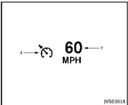
text_image
60 MPH JVS0301XConventional(fixedspeed)cruise controlmodedisplayandindicators
Thedisplayislocatedinthevehicle informationdisplay.
- Cruiseindicator:
This indicator indicates the precondition of ICC system depending on acolor.
- CruisecontrolONindicator(white): IndicatesthattheMAINswitchisON.
- Cruisecontrolsetindicator(green): Displayswhilethevehiclespeedis controlledbytheconventional(fixed speed)cruisecontrolmodeofthe
Startinganddriving5-75
ICCsystem.
- Cruisecontrolsystemwarning(orange): Indicatesthatthereisamalfunction inthelCCsystem.
- Set vehiclespeed indicator:
This indicator indicates the vehicle speed.
ForCanadianmodels,thespeedis displayedinkm/h.
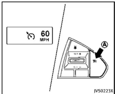
text_image
60 MPH JVS0223XOperatingconventional(fixed speed)cruisecontrolmode Toturnontheconventional(fixedspeed) cruisecontrolmode, pushandholdthe MAINswitch Ⓐ forlongerthanabout1.5 seconds.
WhenpushingtheMAINswitchon,the conventional(fixedspeed)cruisecontrol modedisplayandindicatorsaredisplayed inthevehicleinformationdisplay.After you hold the MAIN switch on for longer than about 1.5 seconds, the Intelligent Cruise Control (ICC) system display goes out. The cruise indicator appears. You can nowsetyourdesiredcruisingspeed. PushingtheMAINswitchagainwillturn thesystemcompletelyoff.
WhentheDistanceControlAssist(DCA) systemison,theconventional(fixed speed)cruisecontrolmodecannotbe turnedoneventhoughtheMAINswitchis pushedandheld.
Toturnontheconventional(fixedspeed) cruisecontrolmode,turnofftheDCA system.See“DistanceControlAssist (DCA)system”(P.5-79).
Whentheignitionswitchispushedtothe OFFposition,thesystemisalsoautomaticallyturnedoff.TousethelIntelligent CruiseControlagain,quicklypushand releasetheMAINswitch(vehicle-to-vehicle distancecontrolmode)orpushandholdit (conventional cruise control mode) again to turniton.

CAUTION
To avoid accidentally engaging cruise control, makes sure to turn the MAIN switch off when not using the Intelligent Cruise Control system.
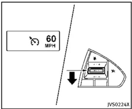
text_image
60 MPH JVS0224XTosetcruisingspeed,accelerateyour vehicletothedesiredspeed,pushthe SET/COAST(-)switchandreleaseit.(The colorofthecruiseindicatorchangesto greenandsetvehiclespeedindicator comeson.)Takeyourfootofftheacceleratorpedal.Yourvehiclewillmaintainthe setspeed.
- Topassanothervehicle, depress the acceleratorpedal. When you release the pedal, the vehicle will return to the previously sets speed.
●Thevehiclemaynotmaintaintheset speedwhengoingupordownsteep hills.Ifthishappens,manuallymain-
tainvehiclespeed.
Tocancelthepresetspeed, useanyofthe followingmethods:
- Push the CANCEL switch. The vehicle speed indicator will go out.
- Tapthebrakepedal. The vehiclespeed indicator will go out.
- TurntheMAINswitchoff. Both the cruise indicator and vehiclespeed indicator will go out.
Toresetatafastercruisingspeed, use one of the following three methods:
- Depresstheacceleratorpedal. When the vehicle attainsthedesiredspeed, pushandreleasetheSET/COAST(-) switch.
- PushandholdtheRESUME/ACCELERATE(+)switch. Whenthevehicleattains thespeedyoudesire, releasethe switch.
3.Push, then quickly releasetheRE-SUME/ACCELERATE(+) switch. Each timeyoudothis, thesetspeedwill increase by about 1 MPH (1.6 km/h).
To reset at a slower cruising speed, use one of the following three methods:
- Lightlytapthebrakepedal. Whenthe vehicleattainsthedesiredspeed, push theSET/COAST(-)switchandreleaseit.
- PushandholdtheSET/COAST(-) switch. Releasetheswitchwhenthe vehicleslowsdowntothedesired speed.
3.Push, then quickly releasethe SET/COAST(-) switch. Each time you do this, the sets speed will decrease by about 1 MPH(1.6km/h).
Toresumethepresetspeed, pushand release the RESUME/ACCELERATE(+) switch. The vehicle will resumethelast setcruisingspeed when the vehiclespeed is over 25 MPH (40 km/h).
Automaticcancellation
Achimesoundsunderthefollowingconditionsandthecontrolisautomatically canceled.
- Whenthevehicleslowsdownmore than8MPH(13km/h)belowtheset speed
- WhentheshiftleverisnotintheD (Drive)ormanualshiftmode
- Whentheparkingbrakeisapplied.
- WhentheVDCoperates(including the tractioncontrolsystem) - Whenatireslips
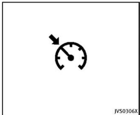
text_image
JVS0306XhavethevehiclecheckedatanINFINITI retailer.
Warning
Whenthesystemisnotoperatingproperly, thechimesoundsandthecolorofthe cruiseindicatorwillchangetoorange.
Actiontotake:
Ifthecolorofthecruise indicator changes toorange, parkthevehicleinasafeplace. Turntheengineoff, restarttheengine, resumedrivingandthenperform the settingagain.
If it is not possible to set or the indicator stays on, it may indicate that the system is malfunctioning. Although the vehicle is still driveable under normal conditions,
5-78 Startinganddriving
DISTANCECONTROLASSIST(DCA)SYSTEM (ifsoequipped)
TheDistanceControlAssist(DCA)system brakesandmovestheacceleratorpedal upwardaccordingtothedistancefromand therelativespeedofthevehicleaheadto helpassistthedrivertomaintaina followingdistance.

WARNING
●Alwaysdrivecarefullyandattentively whenusingtheDCAsystem.Readand understandtheOwner'sManualthoroughlybeforeusingtheDCAsystem.To avoidseriousinjuryordeath,donotrely onthesystemtopreventaccidentsorto controlthevehicle'sspeedinemergency situations.DonotusetheDCAsystem exceptinappropriateroadandtraffic conditions.
- Ifthevehicleaheadcomestoastop, the vehicledeceleratestoastandstillwithin the limitationsofthesystem. The systemwillcancelonceitjudgesthat thevehiclehascometoastandstillwith awarningchime.Topreventthevehicle frommoving,thedrivermustdepress thebrakepedal.
- TheDCAsystemwillnotapplybrake controlwhilethedriver'sfootisonthe
acceleratorpedal.

Information Provided by: DEALER

text_image
JVS0235XPRECAUTIONSONDCASYSTEM
Thesystemisintendedtoassistthedriver tokeepafollowingdistancefromthe vehicleaheadtravelinginthesamelane anddirection.
Iftheradarsensor Ⓐ detectsaslower movingvehicleahead, thesystemwill reducethevehiclespeedtohelpassist thedrivertomaintainafollowingdistance.
Thesystemautomaticallycontrolsthe throttleandappliesthebrakes(upto approximately40%ofvehiclebraking power)ifnecessary.
Thedetectionrangeofthesensoris
Startinganddriving5-79
approximately650ft(200m)ahead.

WARNING
- This system is only an aid to assist the driver and not a collision warning or avoidance device. It is the driver's responsibility to stay alert, drives safely and be in control of the vehicle at all times.
- This system will not adapt automatically toroad conditions. Donot us the system on road with sharp curves, or on icy roads, in heavy rain or infog.
Thedistancesensorwillnotdetectthe followingobjects:
●Stationaryandslowmovingvehicles
●Pedestriansorobjectsintheroadway
●Oncomingvehiclesinthesamelane
●Motorcyclestravelingoffsetinthetravel lane

WARNING
- Asthereisaperformancelimit tothe distancecontrolfunction,neverrely
5-80Startinganddriving
solelyontheDCAsystem.Thissystem doesnotcorrectcareless,inattentiveor absent-mindeddriving,orovercome poorvisibilityinrain,fog,orotherbad weather.Deceleratethevehiclespeedby depressingthebrakepedal,depending onthedistancetothevehicleaheadand thesurroundingcircumstancesinorder tomaintainasafedistancebetween vehicles.
- Thesystemmaynotdetectthevehiclein frontofyouincertainroadorweather conditions. Toavoidaccidents,neveruse theDCAsystemunderthefollowing conditions:
— Onroadswithsharpcurves
— Onslipperyroadsurfacessuchas oniceorsnow,etc.
— Duringbadweather(rain,fog,snow, etc.)
— Whenrain, snowordirtadhereto thesystemsensor
— Onsteepdownhill roads(frequent braking may result in overheating the brakes)
— On repeated uphill and downhill roads
- In some road or traffic conditions, a vehicleorobjectcanunexpectedlycome intothesensordetectionzoneandcause automaticbraking.Youmayneedto controlthedistancefromothervehicles usingtheacceleratorpedal.Alwaysstay alertand avoidusing theDCA system whenitisnotrecommended inthis section.
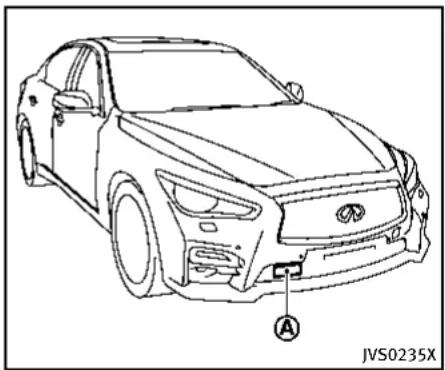
natural_image
Line drawing of a car front view with labeled component A, no text or symbols presentDCASYSTEMOPERATION
Alwayspayattentiontotheoperationof thevehicleandbereadytomanually deceleratetomaintaintheproperfollowing distance.TheDistanceControlAssist(DCA) systemmaynotbeabletodeceleratethe vehicleundersomecircumstances.
TheDCAsystemusesasensor located behindthelowergrilleofthefrontbumper todetectvehiclestravelingahead.
The following aresome conditions in which the sensor cannot detect the signals:
- Whenthesnoworroadsprayfrom travelingvehiclesreducesthesensor's
visibility
- Whenexcessivelyheavybaggageis loadedintherearseatortheluggage roomofyourvehicle
TheDCAsystemisdesignedtoautomaticallycheckthesensor'soperation.When thesensorareaofthefrontbumperis coveredwithdirtorisobstructed,the systemwillautomaticallybecanceled.If thesensorareaiscoveredwithice,a transparentortranslucentvinylbag,etc., theDCAsystemmaynotdetectthem.In theseinstances,theDCAsystemmaynot beabletodeceleratethevehicleproperly. Besuretocheckandcleanthesensorarea regularly.
The DCAsystemisdesignedtohelpassist thedrivertomaintinafollowingdistance fromthevehicleahead.Thesystemwill decelerateasnecessaryandifthevehicle aheadcomestoastop,thevehicle deceleratestoastandstill.However,the DCAsystemcanonlyapplyuptoapproximately40%ofthevehiclestotalbraking power.Ifavehiclemovesintothetraveling lane ahead or if a vehicle traveling ahead rapidly decelerates, the distance between vehicles may become closer because the DCA system cannot decelerate the vehicle
quicklyenough. If this occurs, the DCA system will sound awarning chime and blink the system display to notify the driver to take necessary action.
See "Approachwarning" (P.5-86).
Thisystemonlybrakesandmovesthe acceleratorpedalupwardtohelpassistthe drivertomaintinafollowingdistance fromthevehicleahead.Acceleration shouldbeoperatedbythedriver.
The DCAsystemdoesnotcontrolvehicle speedorwarnyouwhenyouapproach stationaryandslowmovingvehicles.You mustpayattentiontovehicleoperationto maintainproperdistancefromvehicles ahead.
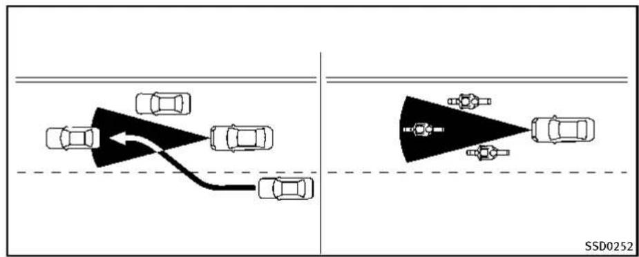
text_image
SSD0252The detection zone of the sensor is limited. A vehicle ahead must be in the detection zone for the system to operate.
Avehicleaheadmaymoveoutsideofthe detectionzoneduetoitspositionwithin thesamelaneoftravel.Motorcyclesmay notbedetectedinthesamelaneaheadif theyaretravelingoffsetfromthecenterline ofthelane.Avehiclethatisenteringthe laneaheadmaynotbedetecteduntilthe vehiclehascompletelymovedintothe lane.Ifthisoccurs,thesystemmaywarn youbyblinkingthesystemindicatorand soundingthechime.Thedrivermayhave tomanuallycontroltheproperdistance
awayfromvehicletravelingahead.

Information Provided by: DEALER
5-82Startinganddriving
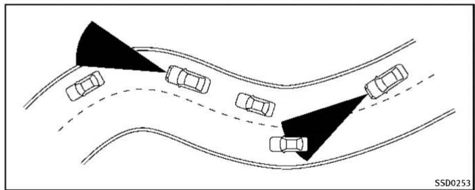
natural_image
Diagram showing multiple cars on curved road with shaded triangular zones, no text or symbols presentWhendrivingonsomeroads,suchas winding,hilly,curved,narrowroads,or roadswhichareunderconstruction,the sensormaydetectvehiclesinadifferent lane,ormaytemporarilynotdetecta vehicletravelingahead.Thismaycause thesystemtoworkinappropriately. Thedetectionofvehiclesmayalsobe affectedbyvehicleoperation(steering maneuverortravelingpositioninthelane, etc.)orvehiclecondition.Ifthisoccurs,the systemmaywarnyoubyblinkingthe systemindicatorandsoundingthechime unexpectedly.Youwillhavetomanually controltheproperdistanceawayfromthe
vehicletravelingahead.

Information Provided by: DEALER

text_image
1 2 JVS0225XDCAsystemdisplayandindicators Thedisplayislocatedbetweenthespeed- ometerandtachometer.
1.Driverassistsystemforwardindicator
- Driverassistsystemforwardindicator(green): IndicatesthattheDCAsystemisON.
-
Driverassistsystemforwardindicator(Orange): Indicateswhetherthereisamal-functionintheDCAsystem.
-
Vehicleaheaddetectionindicator:
Indicateswhetheritdetectsavehiclein
Startinganddriving5-83
frontofyou.

natural_image
Technical line drawing of a car front panel with a black arrow pointing to a circular component (no text or symbols)Dynamicdriverassistanceswitch
OperatingDCAsystem
The DCAsystemturnsonwhenthe dynamicdriverassistanceswitchonthe steeringwheelispushedwhenthe[DistanceControlAssist]isenabledinthe settingsmenuonthelowerdisplay.The driverassistsystemforwardindicator (green)appearsinthevehicleinformation displaywhentheDCAsystemmisturnedon.
Thesystemwillstarttooperateafterthe vehicle speed becomes above approximately3 MPH (5 km/h).

natural_image
Top-down schematic of a vehicle dashboard with front panel, rear seats, and control panel (no text or symbols)Perform the following step to enable or disable the DCAsystem.
- Push the MENU ① button and touch [Driver Assistance] on the lower display.
- Touch[ForwardAssist].
- Touch[DistanceControlAssist]toenableordisablethesystem.
Underthefollowingconditions,theDCA systemwillnotoperateandthe"currently unavailable"warningmessagewillappear inthevehicleinformationdisplay:
5-84 Startinganddriving
- WhentheINFINITIDriveModeSelector isturnedtotheSNOWmode(Tousethe DCAsystem,turntheINFINITIDrive ModeSelectortoamodeotherthanthe SNOWmode,thenturnonthedynamic driverassistanceswitch.) FordetailsabouttheINFINITIDrive ModeSelector,see“INFINITIDrive ModeSelector”(P.5-21).
- WhentheVDCsystemisoff(Tousethe DCAsystem,turnontheVDC,then pushthedynamicdriverassistance switch.) FordetailsabouttheVDCsystem,see "VehicleDynamicControl(VDC)system"(P.5-108).
- WhenABSorVDC(includingthetrractioncontrolsystem)isoperating WhentheConventional(fixedspeed)cruise controlmodeisoperating,theDCAsystem willnotoperate.(TousetheDCAsystem, turntheConventional(fixedspeed)cruise controlmodeoff,thenpushthedynamic driverassistanceswitch.)
FordetailsabouttheConventional(fixed speed)cruisecontrolmode,see "IntelligentCruiseControl(ICC)system"(P.5-58).
Whentheengineisturnedoff, the DCA systemisautomaticallyturnedoff.
①


②

③
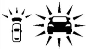
natural_image
Two stylized car icons: one with radiating lines and the other with a sunburst effect (no text or symbols)JVS0244X
- Systemsetdisplaywithvehicle ahead
- Systemsetdisplaywithoutvehicle ahead
- Systemsetdisplaywithvehicle ahead(brakeoperationisnecessary)
Systemoperation

WARNING
The Distance Control Assist (DCA) system automatically decelerates your vehicle to help assist the driver to maintain a following distance from the vehicle ahead. Manu-
allybrakewhendecelerationisrequiredto maintainasafedistanceuponsudden braking by the vehicle ahead or when a vehiclesuddenlyappearsinfrontofyou. AlwaysstayalertwhenusingtheDCA system.
TheDistanceControlAssist(DCA)system helps assist the drivertokeep following distancetothevehicleahead by braking and moving the accelerator pedal upward in thenormaldriving condition.
Whenavehicleaheadisdetected:
The vehicle ahead detection indicator comes on.
Whenthevehicleapproachesavehicle ahead:
- If the driver's foot is not on the accelerator pedal, the system activates the brake stodecelerates smoothly as necessary. If the vehicle ahead comes to stop, the vehicle decelerates to a standstill within the limitations of the system.
- If the driver's foot is on the accelerator pedal, the system movesthe accelerator pedal upward to assist the driverto releasethe accelerator pedal.
Whenbrakeoperationbydriverisrequired:
Thesystemalertsthedriverbyawarning chimeandblinkingthevehicleahead detectionindicator.Ifthedriver'sfootis ontheacceleratorpedalafterthewarning, thesystemmovestheacceleratorpedal upwardtoassistthedrivertoswitchtothe brakepedal.
Thestoplightsofthevehiclecomeon whenbrakingisperformedbytheDCA system.
Whenthebrakeoperates, anoisemaybe heard. This is not a malfunction.

WARNING
- When the vehicle ahead detection indicator is not illuminated, system will not control or warn the driver.
- Depending on the position of the accelerator pedal, the system may not be able to assist the divertoreleasethe accelerator pedal appropriately.
- If the vehicle ahead comestoastandstill, the vehicle decelerate to a standstill within the limitations of the system. Thesystem will release brake control with a warning chime once it judge the vehicle is at a stand still. Toprevent the vehicle from moving, the driver must depress the brake pedal. (Thesystem will resume control automatically once the system reaches 3 MPH (5 km/h)).

Information Provided by: DEALER
Overridingthesystem:
The following driver's operation overrides the system operation.
- When the driver depresses the acceleratorpedalevenfurtherwhile the systemismovingtheacceleratorpedal upward,theDCAsystemcontrolofthe acceleratorpedalisanceled.
- Whenthedriver'sfootisontheacceleratorpedal,thebrakecontrolbythesystemisnotoperated.
- Whenthedriver'sfootisonthebrake pedal, neitherthebrakecontrol northe alertbythesystemoperates.
- When the Intelligent Cruise Control (ICC) systemisset, the DCAsystemwillbe cancelled.
Approachwarning
If your vehicle comes closest the vehicle ahead duetorapid deceleration of that vehicle or if another vehicle cuts in, the system warns the driver with the chime and DCAsystem display. Decelerate by depressing the brake pad altomaintain a safe vehicled distance if:
●Thechimesounds.
- The vehicle ahead detection indicator blinks.
- Thedriverassistsystemforwardindicator(orange)blinks.
- Whenthevehiclesaretravelingatthe samespeedandthedistancebetween vehiclesisnotchanging
- Whenthevehicleaheadistraveling fasterandthedistancebetweenvehiclesisincreasing
- Whenavehiclecutsinnearyourvehicle Thedriverassistsystemforwardindicator (orange)blinksandthewarningchimewill notsoundwhenyourvehicleapproaches vehiclesthatareparkedormovingslowly.

text_image
SSD0284A A SSD0284ANOTE:
Theapproachwarningchimemaysound andthedriverassistsystemforward indicator(orange)mayblinkwhenthe radarsensordetectsobjectsonthesideof thevehicle ① oronthesideoftheroad ②. ThismaycausetheDCAsystemto decelerateoracceleratethevehicle.The radarsensormaydetecttheseobjects whenthevehicleisdrivenonwinding roads,narrowroads,hillyroadsorwhen entering or exiting a curve. In these cases you will have to manually control the proper distance ahead of your vehicle. Also, the sensor sensitivity can be affected byvehicleoperation(steeringmaneuveror drivingpositioninthelane)ortrafficor vehiclecondition(forexample,ifvehicle isbeingdrivenwithsomedamage).
Automaticcancellation
ConditionA:
Underthefollowingconditions,theDistanceControlAssist(DCA)systemis automaticallycanceled.Thechimewill soundandthe"currentlyunavailable" warningmessagewillappearinthevehicle informationdisplay.Thesystemwillnotbe abletobeset.
- WhentheVDCsystemisturnedoff
- WhentheVDCorABS(including the tractioncontrolsystem) operates
- WhentheINFINITIDriveModeSelector isturnedtotheSNOWmode
- Whentheradarsignalistemporarily interrupted.
Actiontotake:
Whentheconditionslistedaboveareno longerpresent,turntheDCAsystemback ontousethesystem.
ConditionB:
Whentheradarsensorareaofthefront bumperiscoveredwithdirtorisob-
Startinganddriving5-87
structed, making it impossible to detect a vehicle ahead, the DCAsystem is automatically canceled.
Thechimewillsound, thedriverassist systemforwardindicator(orange) and the "frontradarobstruction" warningmessage will appear in the vehicle information display.
Actiontotake:
Ifthedriverassistsystemforwardindicator (orange)andthewarningmessageappear, parkthevehicleinasafeplace,turnthe engineoff.Whentheradarsignalis temporarilyinterrupted,cleanthesensor areaofthefrontbumperandrestartthe engine.Ifthewarningmessagecontinues tobedisplayed,havetheDCAsystem checkedbyanINFINITlretailer.
ConditionC:
When the DCAsystemis not operating properly, the chimesounds, the driver assists system forward indicator (orange) and the system "malfunction" warning message will appear in the vehicle information display.
Actiontotake:
If the driver assists system forward indicator (orange) and the warning message appear, park the vehicle in as a safe place. Turn the engine off, restart the engine, and turn on the DCAsystem again.
Ifitisnotpossibletosethesystemorthe indicatorstayson, itmayindicatethatthe systemismalfunctioning. Although the vehicleisstilldriveableundernormal conditions, havethevehiclecheckedat anINFINITlretailer.
Sensormaintenance
ThesensorfortheDCAsystemiscommon withtheIntelligentCruiseControl(ICC) systemandislocatedbehindthelower grilleofthefrontbumper.
Forthesensormaintenance,see"IntelligentCruiseControl(ICC)system"(P.5-58).
FCCNotice:
ForUSA:
ThisdevicecomplieswithPart15ofthe FCCRules.Operationissubjecttothe following two conditions:
-
This device may not cause harmful interference, and
-
This device must accept any interference received, including interference that may cause undesired operation.
FCCWarning
Changesormodificationnotexpressly approvedbythepartyresponsiblefor compliancecouldvoidtheuser'sauthority tooperatetheequipment.
ForCanada:
This device complies with Industry Canada licence-exempt RSS standard(s). Operation is subject to the following two conditions:
-
This devicemaynotcause interference, and
-
This device must accept any interference, including interference that may cause undesired operation of the device.
FORWARDEMERGENCYBRAKINGSYSTEM (ifsoequipped)
Theforwardemergencybrakingsystemcan assistthedriverwhenthereisariskofa forwardcollisionwiththevehicleaheadin thetravelinglane.
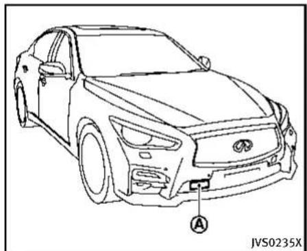
natural_image
Line drawing of a car front view with labeled component A, no text or symbols presentTheforwardemergencybrakingsystem usesaradarsensor locatedbehind thelowergrilleofthefrontbumperto measurethedistancetothevehicleahead inthetravelinglane.
Theforwardemergencybrakingsystem operatesatspeedsaboveapproximately 3MPH(5km/h).Ifthereisariskofacollision,theforwardemergencybraking systemissuesavisualandaudiblewarningandpushestheacceleratorpedalup.If the driver releases the accelerator pedal, then the forward emergency braking system applies partial braking. If the driver does not take action, the forward emer-
gencybrakingsystemissuesthesecond visualandaudiblewarning,andapplies harderbraking.

WARNING
- Theforwardemergencybrakingsystem isasupplementalaidtothedriver.Itis notareplacementforthedriver'sattentiontotrafficconditionsorresponsibility todrivesafely.Itcannotpreventaccidentsduetocarelessnessordangerous drivingtechniques.
- Theforwardemergencybrakingsystem doesnotfunctioninalldriving,traffic, weatherandroadconditions.
| Warning | Visual | Aud ble |
| First warning | Ch me | |
| Second warning | Higher pitched ch me |
| Warning | Visual | Aud ble |
| First warning | 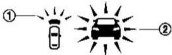 | Ch me |
| Second warning |  | Higher pitched ch me |
1.Driverassistsystemforwardindicator
2. Vehicleaheadetection indicator
SYSTEMOPERATION
The forward emergency braking system will function when your vehicle is driven at speeds above approximately 3 MPH (5 km/h).
Ifariskofaforwardcollisionisdetected, theforwardemergencybrakingsystemwill providethefirstwarningtothedriverby flashingthedriverassistsystemforward indicator(orange)andthevehicleahead detectionindicator(orange),andproviding anaudiblewarning.Inaddition,the
5-90Startinganddriving
forwardemergencybrakingsystempushes theacceleratorpedalup.Ifthedriver releasestheacceleratorpedal,thenthe systemappliespartialbraking.
If the driver appliesthe brakes quickly and forcefully after the warning, and the forward emergency braking system detects that there is still the possibility of a forward collision, the system will automatically increase the braking force.
If a forward collision is imminent and the driver does not take action, the forward emergency braking system issues the second visual (red) and audible warning and automatically applies harder braking.
NOTE:
The vehicle's stoplights come on when braking is performed by the forward emergency braking system.
Depending on vehicles speed and distance to the vehicle ahead, as well as driving and roadway conditions, the system may help the driver avoid a forward collision or may help mitigate the consequences of facollisions should done be unavoidable.
If the driver is handling the steering wheel, accelerating or braking, the forward emergency braking system will function later or will not function.
The automatic braking will cease under the following conditions:
- When theesteeringwheelisturnedas faras necessary to avoid a collision.
- When the accelerator pedal is depressed.
- Whenthereisnolongeravehicle detectedahead.
If the forward emergency braking system has stopped the vehicle, the vehicle will remain at a stand still for approximately 2 seconds before the brakes are released.

WARNING
- Theradarsensordoesnotdetectthe followingobjects:
— Pedestrians, animalsorobstaclesin theroadway
— Oncomingvehicles
— Crossingvehicles
- Theradarsensorhassomeperformance limitations. Forstationary vehicles, the forwardemergencybrakingsystem will not function when the vehicle is driven at speed over approximately 45 MPH (70km/h).
- Theradarsensormaynotdetecta vehicleaheadinthefollowingconditions:
— Dirt, ice, snoworothermaterial coveringtheradarsensor.
— Interferencebyotherradarsources.
— Snoworroadsprayfromtraveling vehicles.
— Ifthevehicleaheadisnarrow(e.g. motorcycle)
— Whendrivingonasteepdownhill slopeorroadswithsharpcurves.
- Insomeroadortrafficconditions, the forwardemergencybrakingsystemmay unexpectedlypushtheacceleratorpedal uporapplypartialbraking.Whenaccelerationisnecessary,continuetodepress theacceleratorpedaltooverridethe system.
●Brakingdistancesincreaseonslippery surfaces. - Excessivenoisewillinterferewiththe warningchimesound,andthechime maynotbeheard.

natural_image
Top-down schematic of a vehicle dashboard with labeled components (no text or symbols beyond label)Turning the forward emergency brakingsystem ON/OFF
Perform the following step to turn the forward emergency braking system on or off.
- Push the MENU button ① and touch [Driver Assistance] on the lower display.
- Touch[EmergencyAssist].
- Touch[Forwardemergencybraking]to turnthesystemON/OFF.

Information Provided by: DEALER

JVS0299X
Forwardemergencybrakingsystemwarninglight(orange)
When the forward emergency braking system is turned off, the forward emergency braking system warning light (orange) will illuminate.
Theforwardemergencybrakingsystemwill remainONorOFFunlessthesettingis changedonthelowerdisplay. Thissetting isalsolinkedwiththelog-infunction.(See "Log-infunction"(P.3-14)andthelnfiniti InTouchOwner'sManualforthelog-in function.)
NOTE:
When the forward emergency braking system setting is turned ON or OFF, the predictive forward collision warnings system is also turned ON or OFF simultaneously.
Systemtemporarilyunavailable
ConditionA:
Whentheradarsensorpicksupinterferencefromanotherradarsource,makingit impossibletodetectavehicleahead,the forwardemergencybrakingsystemis automaticallyturnedoff.Theforward emergencybrakingsystemwarninglight (orange)andthedriverassistsystem forwardindicator(orange)willilluminate.
Actiontotake:
When the above conditions nolonger exist, the forward emergency braking system will resume automatically.
ConditionB:
Whenthesensorareaofthefrontbumper iscoveredwithdirtorisobstructed, making it impossible to detect a vehicle ahead, the forward emergency braking system is automatically turned off. The forward emergency braking system warninglight(orange)willilluminateandthe "frontradarobstruction" warningmessage willappearinthevehicleinformation display.
Actiontotake:
Ifthewarninglight(orange)comeson, parkthevehicleinasafeplace,andturn theengineoff.Cleantheradarcoveron lowergrillewithasoftcloth,andrestart theengine.Ifthewarninglightcontinues toilluminate,havetheforwardemergency brakingsystemcheckedbyanINFINITI retailer.
ConditionC:
When the accelerator pedal actuator detects that the internal motortemperature is high, the forward emergency braking system is automatically turned off. The forward emergency braking system warning light (orange) and the driver assists system forward indicator (orange) will illuminate and the "Unavailable High Accelerator Temperature" warning message will appear in the vehicle information display.
Actiontotake:
When the above conditions nolongerexist, the forward emergency braking system will resume automatically.
Systemmalfunction
If the forward emergency braking system malfunctions, it will be turned off automatically, achimewillsound, the forward emergency braking system warning light (orange) and the driver assists system forward indicator (orange) will illuminate and the system "malfunction" warning message will appear in the vehicle information display.
Actiontotake:
If the warning light (orange) comes on, park the vehicle in as a felocation, turn the engine off and restart the engine. If the warning light continues to illuminate, have the forward emergency braking system checked by an INFINIT retailer.
Sensormaintenance
Fortheradarsensormaintenance, see "IntelligentCruiseControl(ICC)system" (P.5-58).
FCCNotice:
ForUSA:
ThisdevicecomplieswithPart15ofthe FCCRules.Operationissubjecttothe followingtwoconditions:
- This device may not cause harmful interference, and
- This device must accept any interference received, including interference that may cause undesired operation.
FCCWarning
Changesormodificationnotexpressly approvedbythepartyresponsiblefor compliancecouldvoidtheuser'sauthority tooperatetheequipment.
ForCanada:
This device complies with Industry Canada licence-exempt RSS standard(s). Operation is subject to the following two conditions:
- This device may not cause interference, and
- This device must accept any interference, including interference that may cause undesired operation of the device.

Information Provided by: DEALER
PREDICTIVEFORWARDCOLLISION
WARNINGSYSTEM(ifsoequipped)

text_image
1st vehicle 2nd vehicle JVS0294XThepredictiveforwardcollisionwarning systemcanhelpalertthedriverwhenthere isasuddenbrakingofasecondvehicle travelinginfrontofthevehicleaheadin thetravelingsamelane.

natural_image
Line drawing of a sedan car with labeled component A, no text or symbols present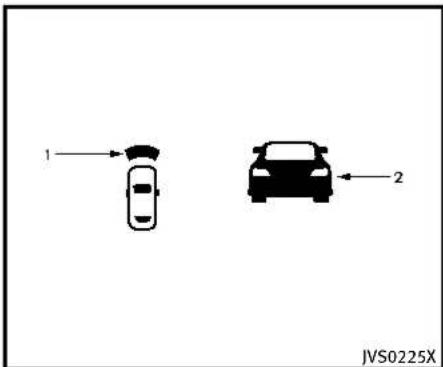
text_image
1 2 JVS0225X
Information Provided by: DEALER
5-94 Starting and driving
1.Driverassistsystemforwardindicator
2. Vehicleaheadetection indicator
SYSTEMOPERATION
Thepredictiveforwardcollisionwarning systemusesaradarsensor located behindthefrontbumpertomeasurethe distancetoasecondvehicleaheadinthe travelinglane. Thepredictiveforwardcollisionwarningsystemoperatesatspeeds aboveapproximately3MPH(5km/h). If thereisapotentialriskofaforward collision, thepredictiveforwardcollision warningsystemwillwarnthedriverby blinkingthedriverassistsystemforward indicatorandthevehicleaheaddetection indicator, andsoundingawarningtone.
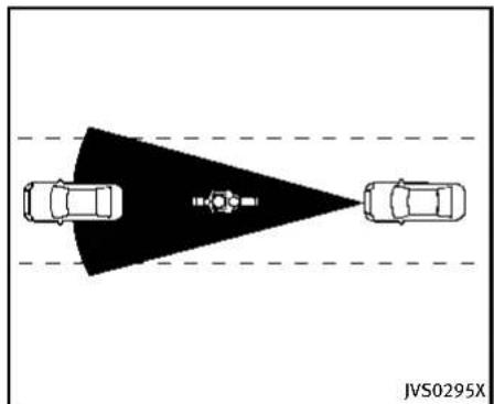
natural_image
Top-down diagram of a vehicle showing two cars facing each other with a shaded triangular area and a central sensor or camera icon, no text or symbols present.Precautionsonthepredictiveforwardcollisionwarningsystem

WARNING
- The predictive forward collision warning system is designed to warn you before a collision but will not avoid a collision. It is the driver's responsibility to stay alert, drives safely and be in control of the vehicle at all times.
- The radar sensor does not detect the following objects:
— Pedestrians, animalsorobstaclesin theroadway
— Oncomingvehicles
— Crossingvehicles
- The predictive forward collision warning system does not function when a vehicle ahead is an arrow vehicle, such as a motorcycle.
●Theradarsensormaynotdetecta secondvehicleaheadinthefollowing conditions:
— Snoworheavyrain
— Dirt, ice, snoworothermaterial coveringtheradarsensor
— Interferencebyotherradarsources
— Snoworroadsprayfromtraveling vehiclesissplashed
— Drivinginatunnel
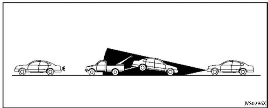
natural_image
Diagram showing three cars on a road with a triangular object and a vehicle, no text or symbols present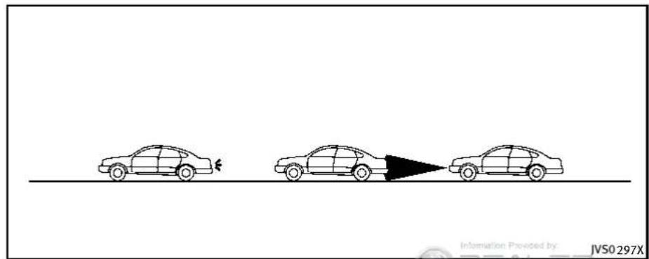
text_image
Information Provided by: JVS0297X
WARNING
- Theradarsensormaynotdetecta secondvehiclewhenthevehicleahead isbeingtowed.
- Whenthedistancetothevehicleahead istooclose, thebeamoftheradar sensorisobstructed.
5-96Startinganddriving
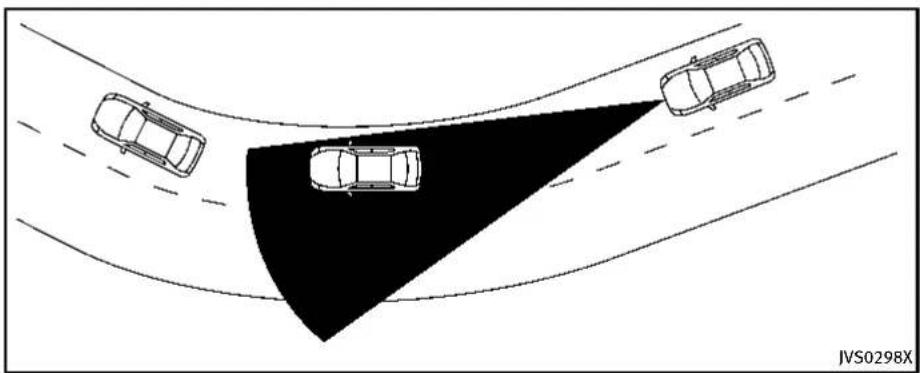
natural_image
Top-down diagram of three cars on curved surfaces with a shaded triangular area, no text or symbols present
WARNING
- Theradarsensormaynotdetecta secondvehiclewhendrivingonasteep downhillslopeoronroadswithsharp curves.
- Excessivenoisewillinterferewiththe warningtonesound, anditmaynotbe heard.
predictiveforwardemergencywarning systemisalsoturnedONorOFFsimultaneously.
NOTE:
Whentheforwardemergencybraking systemsettingisturnedONorOFF,the

Information Provided by: DEALER
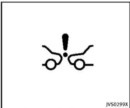
text_image
JVS0299XForwardemergencybrakingsystemwarninglight(orange)
Systemtemporarilyunavailable
ConditionA:
Whentheradarsensorpicksupinterferencefromanotherradarsource,makingit impossibletodetect Vehicleahead,the predictiveforwardcollisionwarningsystemisautomatically turnedoff.Theforwardemergencybrakingsystemwarning light(orange)andthedriverassistsystem forwardindicator(orange)willilluminate.
Startinganddriving5-97
Actiontotake:
When the above conditions no longer exist, the predictive forward collision warning system will resume automatically.
ConditionB:
When the sensor area of the front bumper is covered with dirtoris obstructed, making it impossible to detect vehicle ahead, the predictive forward collision warnings system is automatically turned off. The forward emergency braking system warning light (orange) and the driver assist system forward indicator (orange) will illuminate and the "frontradarobstruction" warning message will appear in the vehicle information display.
Actiontotake:
Ifthewarninglight(orange)comeson, parkthevehicleinasafeplace,andturn theengineoff.Cleantheradarcoveron lowergrillewithasoftcloth,andrestart theengine.Ifthewarninglightcontinues toilluminate,havethepredictiveforward collisionwarningsystemcheckedbyan INFINITlretailer.
Systemmalfunction
If the predictive forward collision warning system malfunctions, it will be turned off automatically, achimewillsound, the forward emergency braking system warning light (orange) and the driver assist system forward indicator (orange) will illuminate, and the system malfunction messagewill appear in the vehicle information display.
Actiontotake:
If the warning light (orange) illuminates, park the vehicle in as a felocation, turn the engine off and restart the engine. If the warning light continues to illuminate, have the predictive forward collision warning system checked by an INFINIT retailer.
Sensormaintenance
Fortheradarsensormaintenance, see "IntelligentCruiseControl(ICC)system" (P.5-58).
FCCNotice:
ForUSA:
This device complies with Part 15 of the FCC Rules. Operation is subject to the following two conditions:
-
This devicemay not cause harmful interference, and
-
This device must accept any interference received, including interference that may cause undesired operation.
FCCWarning
Changesormodificationnotexpressly approvedbythepartyresponsiblefor compliancecouldvoidtheuser'sauthority tooperatetheequipment.
ForCanada:
This device complies with Industry Canada licence-exempt RSS standard(s). Operation is subject to the following two conditions:
-
This device may not cause interference, and
-
This device must accept any interference, including interference that may cause undesired operation of the device.
BREAK-INSCHEDULE

CAUTION
During the first 1,200 miles (2,000 km), follow the recommendation to obtain maximum engine performance and ensure the futurer reliability and economy of your new vehicle.
Failure to follow these recommendations may result in shortened engine life and reduced engine performance.
- Avoiddrivingforlongperiodsatconstantspeed,eitherfastorslow.Donot runtheengineover4,000rpm.
- Donotaccelerateatfullthrottleinany gear.
- Avoidquickstarts.
●Avoidhardbrakingasmuchaspossible.
FUELEFFICIENTDRIVINGTIPS
Followtheseeasy-to-useFuelEfficient DrivingTipstohelpyouachievethemost fueleconomyfromyourvehicle.
-
Uses smooth accelerator and brake pedal application.
-
Avoidrapidstartsandstops.
- Usesmooth, gentleaccelerator and brake application whenever possible.
-
Maintainconstantspeedwhilecommutingandcoastwheneverpossible.
-
Maintainconstantspeed.
-
Lookaheadtotryandanticipateand minimizestops.
- Synchronizingyourspeedwithtrafficlightsallowsyoutoreduceyour numberofstops.
-
Maintainingasteadyspeedcan minimizedlightstopsandimprovefuelefficiency.
-
Use air conditioning (A/C) at higher vehicle speeds.
-
Below40MPH(64km/h), it is more efficient to open windows to cool the vehicle due to reduced engine load.
- Above 40 MPH (64 km/h), it is more efficient to use A/C to cool the vehicle due to increased aerody-
namicdrag.
- Recirculating the cool air in the cabin when the A/Cison reduces cooling load.
-
Driveateconomicals speeds and distances.
-
Observingthespeedlimitandnot exceeding60MPH(97km/h)(where legallyallowed)canimprovefuel efficiencyduetoreducedaerodynamicdrag.
- Maintaining as safe following distance behind other vehicles reduces unnecessary braking.
- Safelymonitoringtrafficioanticipatechangesinspeedpermits reducedbrakingandsmoothaccelerationchanges.
-
Selectagearrangesuitabletoroad conditions.
-
Usecruisecontrol.
-
Usingcruisecontrolduringhighway drivinghelpsmaintinasteady speed.
-
Cruisecontrolisparticularlyeffectiveinprovidingfuelsavingswhen drivingonflatterrains.
-
Planfortheshortestroute.
- Utilizeamapornavigationsystemto determinethebestroutetosave time.
- Avoididling.
- Shuttingoffyourenginewhensafe forstopsexceeding30-60seconds savesfuelandreducesemissions.
- Buyanautomatedpassfortollroads.
- Automatedpassespermitdriversto usespeciallanestomaintaincruisingspeedthroughthetollandavoid stoppingandstarting.
-
Winterwarmup.
-
Limitidlingtimetominimizeimpact tofueleconomy.
- Vehiclestypicallyneednomorethan 30secondsofidlingatstart-upto effectivelycirculatetheengineoil beforedriving.
-
Yourvehiclewillreachitsideal operatingtemperaturemorequickly whiledrivingversusidling.
-
Keeping your vehicle cool.
- Parkyourvehicleinacovered parkingareaorintheshadewhen-everpossible.
5-100Startinganddriving
- Whenenteringahotvehicle, openingthewindowswillhelptoreduce theinsidetemperaturefaster,resultinginreduceddemandonyourA/C system.
INCREASINGFUELECONOMY
- Keepyourenginetunedup.
●Followtherecommended scheduled maintenance. - Keepthetiresinflatedtothecorrect pressure.Lowtirepressureincreases tirewearandlowersfueleconomy.
- Keepthewheelsincorrectalignment. Improperalignmentincreasestirewear andlowersfueleconomy.
- Usetherecommendedviscosityengine oil.(See"Engineoilandoilfilter recommendation"(P.9-6).)

Information Provided by: DEALER
INTELLIGENTALL-WHEELDRIVE(AWD)(ifso equipped)
Ifanymalfunctionoccursinthelntelligent All-WheelDrive(AWD)systemwhilethe engineisrunning, warningmessages appearinthevehicleinformationdisplay.

flowchart
graph TD
    A["AWD\nAWD Error\nSee Owner's Manual"] -->|①| B["AWD\nAWD High Temp.\nStop Vehicle"]
    B -->|②| C["AWD\nTire Size Incorrect\nSee Owner's Manual"]
    C -->|③| D["JVS0228M"]
Ifthe "AWDError" warning ① appears, theremaybeamalfunctioninthIntelligentAWDsystem.Reducevehiclespeed and have your vehicle checked by an INFINITI retailer as soon as possible. The "AWD High Temp." (high temperature) warning ② may appear while trying to free
astuckvehicleduetoincreasedoil temperature. Thedrivingmodemaychange toTwo-WheelDrive(2WD). If this warning is displayed, stop the vehicle with the engineidling, as soon as it's a tetodoso. Then if the warning turn soff, you can continued driving.
The "TireSizelncorrect" warning ③ may appear if there is a larged difference between the diameters off front and rear wheels. Pullofftherodinasafe area, with the engine idling. Check that all tire sizes are these same, that the tire pressure is correct and that the tires are not excessively worn.
Ifanywarningmessagecontinuestobe displayed, haveyourvehiclecheckedbyan INFINITlretailerassoonaspossible.

WARNING
- ForAWDequippedvehicles, donot attempttoraisetwowheelsoffthe groundandshiftthetransmissionto anydriveorreversepositionwiththe engineerunning.Doingsomayresultin drivetraindamageorunexpectedvehicle movementwhichcouldresultinserious vehicledamageorpersonalinjury.
Startinganddriving5-101
- DonotattempttotestanAWDequipped vehicleona2-wheeldynamometer(such asthedynamometersusedbysome statesforemissionstesting)orsimilar equipmenteveniftheothertwowheels areraisedofftheground.Makesurethat youinformthetestfacilitypersonnel thatyourvehicleisequippedwithAWD beforeitisplacedonadynamometer. Usingthewrongtestequipmentmay resultindrivetraindamageorunexpectedvehiclemovementwhichcould resultinseriousvehicledamageor personalinjury.

CAUTION
- Donotoperatetheengineonafree rollerwhenanyofthewheelsareraised.
- If the "AWD Error" warning appears while driving theremaybeam malfunction in the AWD system. Reducethe vehicle speed and have your vehicle checked by an INFINIT retailer as soon as possible.
- If the "AWDError" warningremainson aftertheaboveoperation, have your vehiclecheckedbyanINFINITretaileras
soonaspossible.
- The powertrain may be damaged if you continued driving with the "AWDError" warning.
PARKING/PARKINGONHILLS
①
□
□
□
□


②
□
□
□
□

③
□
□
□
□

SD1006MA

WARNING
- Donotstoporparkthevehicleover flammablematerialssuchasdrygrass, wastepaperorrags. They may ignite and causefire.
●Neverleavetheengineerunningwhilethe vehicleisunattended. -
Donotleavechildrenunattendedinside thevehicle.Theycouldunknowingly activateswitchesorcontrols.Unattendedchildrencouldbecomeinvolved inseriousaccidents.
-
Safeparkingproceduresrequirethat boththeparkingbrakebeappliedand thetransmissionplacedintoP(Park). Failuretodosocouldcausethevehicle tomoveunexpectedlyorrollawayand resultinanaccident.
-
Makesuretheautomatictransmission shiftleverhasbeenpushedasfar forwardasitcangoandcannotbe movedwithoutdepressingthefoot brake pedal.
-
Firmly apply the parking brake.
2.MovetheshiftlevertotheP(Park) position.
3. To help prevent the vehicle from rolling into the street when parked on a sloping driveway, it is good practice to turn the wheels as illustrated.
- HEADEDDOWNHILLWITHCURB: Turnthewheelsintothecurband movethevehicleforwarduntilthe curbsidewheelgentlytouchesthe curb.
- HEADEDUPHILLWITHCURB: ② Turnthewheelsawayfromthecurb andmovethevehiclebackuntilthe curbsidewheelgentlytouchesthe curb.
- HEADEDUPHILLORDOWNHILL, NO CURB: ③
Turnthewheelstowardthesideof theroadsothevehiclewillmove awayfromthecenteroftheroadifit moves.
- PushtheignitionswitchtotheOFF position.
POWERSTEERING
HYDRAULICPOWERSTEERINGTYPE

WARNING
If the engine is not running oristurned off while driving, the power assist for the steering will not work. Steering will be hard to operate.
The power assisted steering uses a hydraulic pump, driven by the engine, to assist steering.
If the engine stops orthedrive belt breaks, you will still have control of the vehicle. However, much greater steering effort is needed, especially in shar turns and at lowspeeds.
DIRECTADAPTIVESTEERINGTYPE

WARNING
Whenthepowersteeringwarninglight illuminateswiththeengineerunning,the powerassistforthesteeringwillcease operation.Youwillstillhavecontrolofthe vehicle,butthesteeringwillbeharderto operate.

CAUTION
- If wheels sortires other than the INFINITI recommended ones are used, the direct adaptive steering system may not operate properly and the power steering warning light may illuminate.
- Donotmodifythevehicle'ssuspension. Ifsuspensionpartssuchasshock absorbers,struts,springs,stabilizer bars,bushingsandwheelsarenot INFINITIrecommendedforyourvehicle orareextremelydeteriorated,thedirect adaptivesteeringsystemmaynotoperateproperlyandthepowersteering warninglightmayilluminate.
- Donotmodifythevehicle'ssteering. If steeringpartsarenotINFINITIrecommendedforyourvehicleorareextremely deteriorated,thedirectadaptivesteeringsystemmaynotoperateproperlyand thepowersteeringwarninglightmay illuminate.
- If the VDC warning light illuminates, the power steering warning light may also illuminate at the same time. Stop the vehicle in a safe location, turn the engine off and restart the engine. If the
powersteeringwarninglight continues toilluminate, havethesystemchecked by an INFNITlretailer. For VDC system, see "VehicleDynamicControl(VDC) system" (P.5-108).
- Donot placetheignitionswitchisinthe ONpositionwhilethesteeringwheelor atireisremoved.
- Donotturnthesteeringwheelasmuch aspossiblewhiletheignitionswitchis inanypositionotherthantheON position.
- Installinganaccessoryonthesteering wheel, or changing thesteeringwheel, may reduce thesteering performance.
The direct adaptive steering system is designed to control the steering force and steering angle according to the vehicle speed and amount of turning of the steering wheel.
Thesteeringcharacteristiccanbeselected withtheINFINITIDriveModeSelector.See "INFINITIDriveModeSelector"(P.5-21).
When the steering wheel is operated repeatedly or continuously while parking or driving at a very low speed, the power assist for the steering wheel will be
reducedandthesteeringwheelmaybe slightlyturnedevenwhendrivingona straightroad. Thisistopreventoverheatingofthedirectadaptivesteeringsystem andprotectitfromgettingdamaged. When the temperatureofthedirectadaptive steeringsystemcoolsdown, thepower assistlevelwillreturntonormal. Avoid repeatingsteeringwheeloperationsthat couldcausethedirectadaptivesteering systemtooverheat.
If the power steering warning light illuminates while the engine is running, it may indicate that the direct adaptive steering system is not functioning properly and may need servicing. Havethesystem checked by an INFINIT retailer. (See "Power steering warning light" (P.2-16).)
Whenthepowersteeringwarninglight illuminateswiththeengineerunning,the powerassistforthesteeringwillcease operation.Youwillstillhavecontrolofthe vehicle.However,greatersteeringeffort willbeneeded,especiallyinsharpturns andatlowspeeds.
If the direct adaptive steering system is malfunctioning, the steering wheel may turn slightly even when driving on a straight road.
Underthefollowingconditions, thesteeringwheelmayturnslightly even when driving on a straightroad. This is duetoa protection mechanism forthedirect adaptive steeringsystem.
●Whenthebatteryisdischarged
●Whentheengineisstalled
●Afterthevehicleistestedonthefour-wheeldynamometer
- Whenthesteeringwheelisheldinthe fulllockpositionorwhenthefronttire touchesanobstruction.
Thesteeringwheelwillreturntothe normalpositionaftertheprotectionmechanismdeactivates. Toreturntothe normalposition,turntheengineoff,restart theengine,andthendrivethevehiclefora periodoftime.
Whenthevehicleistestedonthe2-wheel dynamometer,thepowersteeringwarning lightmayilluminate.Toturnoffthepower steeringwarninglight,stopthevehicleina safelocation,turntheengineoff,restart theengine,andthendrivethevehiclefora periodof time.
The following conditions do not indicate a malfunction of the direct adaptive steering system.
- You may notice wider steering play when the ignition switch is in the OFF or ACC position compared to when it is in the ON position.
●Aftertheengineisstarted, thesteering wheelmayturnslightly even when driving on astraightroad. Toreturn to thenormal position, drivethevehicle on astraightroad for aperiodoftime.
●Aftertheengineisstarted, thesteering wheelmaymoveifthesteeringwheel wasturnedtothefullylockedposition whiletheignitionswitchwasintheOFF position.
Youmayhearanoiseunderthefollowing conditions. However, this is not a malfunction.
- Whentheengineisstartedorstopped.
- When the steering wheel is turned in the full lock position.
BRAKESYSTEM
BRAKINGPRECAUTIONS
Thebrakesystemhastwoseparatehydrauliccircuits. Ifonecircuitmalfunctions, youwillstillhavebrakingattwowheels.
Vacuumassistedbrakes
Thebrakeboosteraidsbrakingbyusing enginevacuum.Iftheenginestops,you canstopthevehiclebydepressingthe brakepedal.However,greaterfootpressureonthebrakepedalwillberequiredto stopthevehicleandthestoppingdistance willbelonger.
Usingthebrakes
Avoidrestingyourfootonthebrakepedal whiledriving. This will cause overheating of the brakes, wearing out the brake and pads faster and reduce gasmileage.
To helps a vet the brakes and to prevent the brakes from overheating, reduces speed and downshift to lower gear before going down aslope or long grade. Overheated brakes may reduce braking performance and could result in loss of vehicle control.

WARNING
- Whiledrivingonaslippery surface, be careful when braking, accelerating or downshifting. Abrupt braking or accelerating could cause the wheel stoskid and result in an accident.
- If the engine is not running oristurned off while driving, the power assist for the brakes will not work. Braking will be harder.
Wetbrakes
Whenthevehicleiswashedordriven throughwater,thebrakesmaygetwet. Asaresult,yourbrakingdistancewillbe longerandthevehiclemaypulltooneside duringbraking.
Todrybrakes, drivethevehicleatasafe speedwhilelightlytappingthebrakepedal toheat-upthebrakes. Dothisuntilthe brakesreturntonormal. Avoiddrivingthe vehicleathighspeedsuntilthebrakes function correctly.
This procedure is described in the vehicle servicemanual and can be performed by an INFINIT retailer.
BRAKEASSIST
BRAKEASSIST
Whentheforceappliedtothebrakepedal exceedsacertainlevel,theBrakeAssistis activatedgeneratinggreaterbrakingforce thanaconventionalbrakeboostereven withlightpedalforce.

WARNING
The Brake Assistisonlyanaidtoassist brakingoperationandisnotacollision warningoravoidancedevice.Itisthe driver's responsibilitytostayalert,drive safelyandbeincontrolofthevehicleatall times.
ANTI-LOCKBRAKINGSYSTEM(ABS)

WARNING
●TheAnti-lockBrakingSystem(ABS)isa sophisticateddevice,butitcannotpreventaccidentsresultingfromcarelessor dangerousdrivingtechniques.Itcan helpmaintainvehiclecontrolduring brakingonslippery surfaces.Remember thatstoppingdistancesonslippery surfaceswillbelongerthanonnormal
surfacesevenwithABS.Stoppingdistancesmayalsobelongeronrough, gravelorsnowcoveredroads,orifyou areusingtirechains.Alwaysmaintaina safedistancefromthevehicleinfrontof you.Ultimately,thedriverisresponsible forsafety.
•Tiretypeandconditionmayalsoaffect brakingeffectiveness.
— Whenreplacingtires,installthe specifiedsizeoftiresonallfour wheels.
— Wheninstallingasparetire, make surethatisthepropersizeand typeasspecifiedontheTireand LoadingInformationlabel.See“Tire andloadinginformationlabel”(P.9-13)ofthismanual.
— Fordetailed information, see "Wheelsandtires"(P.8-29)of this manual.
The Anti-lock Braking System (ABS) control the braking system during hard braking or when braking on slippery surfaces. The system detects the rotation speed at each wheel and varies the brake fluid pressure to prevent each wheelfromlockingandsliding. By preventing each wheelfromlocking, the system helpsthedrivermaintainsteering controlandhelpstominimizeswerving and spinningonslippery surfaces.
Usingthesystem
Depressthebrakepedalandholditdown. Depressthebrakepedalwithfirmsteady pressure, butdonotpumpthebrakes. The ABSwilloperatetopreventthewheels fromlockingup. Steerthevehicletoavoid obstacles.

WARNING
Donotpumpthebrakepedal.Doingsomay resultinincreasedstoppingdistances.
Self-testfeature
TheABSincludeselectronicsensors,electricpumps,hydraulicsolenoidsanda computer.Thecomputerhasabuilt-in diagnosticfeaturethatteststhesystem eachtimeyoustarttheengineandmove thevehicleatalowspeedinforwardor reverse. Whentheself-testoccurs,youmayheara"clunk"noiseand/orfeelapulsa-
VEHICLEDYNAMICCONTROL(VDC)SYSTEM
tioninthebrakepedal. Thisisnormaland doesnotindicateamalfunction. If the computersensesamalfunction, it switches theABSoffandilluminates theABS warninglightontheinstrumentpanel. The brakesystemthenoperates normally, but without anti-lock assistance. If the ABS warning lightilluminates during the self-testor whiledriving, havethe vehicle checked by an INFINIT retailer.
Normaloperation
TheABSoperatesatspeedsabove3to6MPH(5to10km/h).
WhentheABSsensesthatoneormore wheelsareclosetolockingup,theactuator rapidlyappliesandreleaseshydraulic pressure.Thisactionissimilartopumping thebrakesveryquickly.Youmayfeel a pulsationinthebrakepedalandheara noisefromunderthehoodorfeela vibrationfromtheactuatorwhenitis operating.Thisisnormalandindicates thattheABSisoperatingproperly.However,thepulsationmayindicatethatroad conditionsarehazardousandextracareis requiredwhiledriving.
The VehicleDynamicControl(VDC) system uses various sensorstomonitor driver inputs and vehicle motion. Under certain driving conditions, the VDC system helps to perform the following functions.
●Controlsbrakepressureto reduce wheelslipononeslippingdrivewheel sopoweristransferredto anon slippingdrivewheelonthesameaxle.
●Controlsbrakepressureandengine outputtoreducedrivewheelslipbased onvehiclespeed(tractioncontrolfunction).
●Controlsbrakepressureatindividual wheelsandengineoutputtohelpthe drivermaintaincontrolofthevehiclein thefollowingconditions:
—understeer(vehicletendstonot followthesteeredpath despite increasedsteeringinput)
—oversteer(vehicletendstospindue to certain road or driving conditions).
The VDC system can help the driverto maintain control of the vehicle, but it cannot prevent loss of vehicle control in all driving situations.
When the VDC system operates, the VDC warning light in the instrument panel
flashessonotethefollowing:
- Theroadmaybelipperyorthesystem maydeterminesomeactionisrequired tohelpkeepthevehicleonthesteered path.
- Youmayfeelapulsationinthebrake pedalandhearanoiseorvibration fromunderthehood. Thisisnormal andindicatesthattheVDCsystemis workingproperly.
- Adjustyourspeedanddrivingtothe roadconditions.
See "VehicleDynamicControl(VDC)warninglight"(P.2-17).
Ifamalfunctionoccursinthesystem,the VDCwarninglight 📍 illuminatesinthe instrumentpanel.TheVDCsystemautomaticallyturnsoff.
TheVDCOFFswitchisusedtoturnoffthe VDCsystem.TheVDCoffindicatorlight illuminatestoindicatetheVDCsystemis off.WhentheVDCswitchisusedtoturnoff thesystem,theVDCsystemstilloperates topreventonedrivewheelfromslippingby transferringpowertoanonslippingdrive wheel.TheVDCwarninglight flashesif thisoccurs.AllotherVDCfunctionsareoff, exceptforbrakeforcedistribution,andthe VDCwarninglight willnotflash.The
VDCsystemisautomaticallyresettoon whentheignitionswitchisplacedintheoff positionthenbacktotheonposition.
See "VehicleDynamicControl(VDC)warninglight"(P.2-17) and "VehicleDynamic Control(VDC)offindicatorlight"(P.2-19).
Thecomputerhasabuilt-indiagnostic featurethatteststhesystemeachtimeyou starttheengineandmovethevehicle forwardorinreverseataslowspeed. Whentheself-testoccurs,youmayheara "clunk"noiseand/orfeelapulsationinthe brakepedal.Thisisnormalandisnotan indicationofamalfunction.
BRAKEFORCEDISTRIBUTION
Duringbrakingwhiledrivingthroughtturns, thesystemoptimizedredistributionof forcetoeachofthefourwheelsdepending ontheradiusoftheturn.

WARNING
●TheVDCsystemisdesignedtohelpthe drivermaintainstabilitybutdoesnot preventaccidentsduetoabruptsteering operationathighspeedsorbycareless ordangerousdrivingtechniques.Reduce vehiclespeedandbeespeciallycareful
whendrivingandcorneringonslippery surfacesandalwaysdrivecarefully.
- Thebrakeforcedistributionsystemmay notbeeffectivedependingonthedrivingcondition.Alwaysdrivecarefullyand attentively.
- Donotmodifythevehicle'ssuspension. If suspensionpartssuchasshock absorbers,struts,springs,stabilizer bars,bushingsandwheelsarenot INFINITIrecommendedforyourvehicle orareextremelydeteriorated,theVDC systemmaynotoperateproperly.This couldadverselyaffectvehiclehandling performance,andtheVDCwarninglight mayilluminate.
- Ifbrakerelatedpartssuchasbrake pads, rotorsandcalipersarenotINFINITI recommendedorareextremelydeteriorated,theVDCsystemmaynotoperate properlyandtheVDCwarninglight mayilluminate.
- Ifenginecontrolrelatedpartsarenot INFINITIrecommendedorareextremely deteriorated, the VDC warning light may illuminate.
- When driving on extremely inclined surfaces such as higher banked corners,
theVDCsystemmaynotoperateproperlyandtheVDCwarninglight may illuminate.Donotdriveonthesetypes ofroads.
- Whendrivingonanunstablesurface suchasaturntable, ferry, elevator ramp, the VDC warninglight may illuminate. This is not a malfunction. Restart the engine after driving onto a stablesurface.
- If wheels sortires other than the INFINITI recommended ones are used, the VDC system may not operate properly and the VDC warning light may illuminate.
•TheVDCsystemisnotasubstitutefor wintertiresortirechainsonasnow coveredroad.
ACTIVETRACECONTROL
This systems senses driving based on the driver's steering and acceleration/braking patterns, and controls brake pressure at individual wheels and engine output to help smooth vehicular response.
WhentheSPORTmodeisselectedbythe INFINITIDriveModeSelector, theamountof brakecontrolprovidedbytheactivetrace controlisreduced.
When the PERSONAL mode is selected, the activetrace control can be set to ON (enabled) or OFF (disabled). See "INFINITI Drive Mode Selector" (P. 5-21).
When the VDCOFF switch is used to turn off the VDC system, the activetrace control is also turned off.
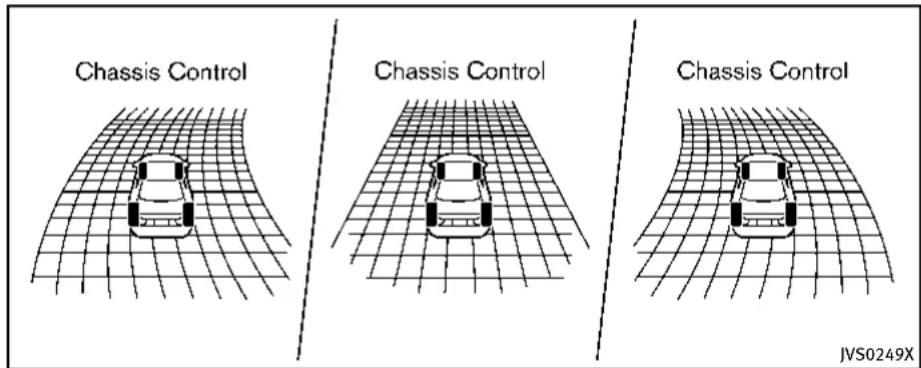
JVS0249X
When the activetrace control is operated and the "Chassis Control" mode is selected in the trip computer, the activetrace control graphics are shown in the vehicle information display. (See "Tripcomputer" (P.2-28).)
If the chassis control warning message appears in the vehicle information display, it may indicate that the active trace control is not functioning properly. Have the system checked by an INFINIT retailer. (See "26. Chassis control warning" (P.2-24).)

Information Provided by: DEALER E. PROCESS

WARNING
Theactivetracecontrolmaynotbeeffective dependingonthedrivingcondition.Always drivecarefullyandattentively.
Whentheactivetracecontrolisoperating, youmayfeelapulsationinthebrakepedal andhearanoise. Thisisnormaland indicatesthattheactivetracecontrolis operatingproperly.
EveniftheactivetracecontrolissettoOFF, somefunctionswillremainontoassistthe
- Neverrelysolelyonthehillstartassist systemtopreventthevehiclefrom movingbackwardonahill.Alwaysdrive carefullyandattentively.Depressthe brakepedalwhenthevehicleisstopped onasteephill.Beespeciallycareful whenstoppedonahillonfrozenor muddyroads.Failureforetopreventthe vehiclefromrollingbackwardsmay resultinalossofcontrolofthevehicle and possibleseriousinjuryordeath.
●Thehillstartassistsystemisnot designed to hold the vehiclea standstillonahill. Depressthebrake pedal when the vehicle is stopped on steephill. Failure todosomaycausethe vehicletor rollbackwards and may result in acollision or serious personal injury.
●Thehillstartassistsystemmaynot preventthevehiclefromrollingbackwardsonahillunderalloadorroad conditions.Alwaysbepreparedtode-press the brake pedal to prevent the vehicle from rolling backwards. Failure to do so may result in a collision or serious personal injury.
Thehillstartassistsystemautomatically keepsthebrakesappliedtohelpprevent thevehiclefromrollingbackwardsinthe timeittakesthedrivertoreleasethebrake pedalandapplytheacceleratorwhenthe vehicleisstoppedonahill.
Thehillstartassistsystemwilloperate automaticallyunderthefollowingconditions:
●Thetransmissionisshiftedtoaforward orreversegear.
●Thevehicleisstoppedcompletelyona hillbyapplyingthebrake.
Themaximumholdingtimeis2seconds. After2secondsthevehiclewillbeginto rollbackandthehillstartassistsystem willstopoperatingcompletely.
Thehillstartassistsystemwillnotoperate whentetransmissionisshiftedtotheN (Neutral)orP(Park)positionoronaflat andlevelroad.
CHASSISCONTROL
Thechassiscontroliselectriccontrol module, including the following function:
- Log-infunction(See"Log-infunction" (P.3-14).)
- INFINITIDriveModeSelector(See "INFINITIDriveModeSelector"(P.5-21).)
●ActiveLaneControl(ifsoequipped) (See“ActiveLaneControl”(P.5-24).)
- ActiveTraceControl(See"Activetrace control"(P.5-110).)
COLDWEATHERDRIVING
FREEINGAFROZENDOORLOCK
Topreventadoorlockfromfreezing,apply deicerthroughthekeyhole.Ifthelock becomesfrozen,heatthekeybefore insertingitintothekeyholeorusethe IntelligentKeysystem.
ANTIFREEZE
Inthewinterwhenitisanticipatedthatthe outsidetemperaturewilldropbelow32°F (0°C),checkantifreezetoassureproper winterprotection.Foradditionalinformation,see"Enginecoolingsystem"(P.8-8).
BATTERY
If the battery is not fully charged during extremelycoldweatherconditions, the batteryfluid mayfreezeand damagethe battery. To maintain maximum efficiency, the batteryshouldbechecked regularly. For additional information, see "Battery" (P.8-15).
DRAININGOFCOOLANTWATER
If the vehicle is left to be left outside without antifreeze, drain the cooling system, including the engine block. Refill before operating the vehicle. For details, see "Engine cooling system" (P.8-8).
TIREEQUIPMENT
SUMMERtireshaveatreaddesignedto providesuperiorperformanceondrypavement. However, the performance of these tires will be substantially reduced in snowy and icy conditions. If you operate your vehicle on snowy or icy roads, INFINITI recommend the use of MUD & SNOW or ALL SEASON tires on all four wheels. Consultant INFINITI retailer forthetire type, size, speed rating and availability information.
For additional attraction on icy roads, studded tires maybe used. However, some U.S. states and Canadian provinces prohibit their use. Check local, state and provincial laws before installing studded tires.
Skidandtraction capabilitiesofstudded snowtires,onwetordrysurfaces,maybe poorerthanthatofnon-studdedsnow tires.
Tirechainsmaybeused. Fordetails, see "Tirechains"(P.8-36) of this manual.
All-WheelDrive(AWD)models
If you install snowtires, they must also be the namesize, brand, construction and tread pattern on all four wheels.
SPECIALWINTEREQUIPMENT
It is recommended that the following items be carried in the vehicle during winter:
- Ascraperandstiff-bristledbrushto removeiceandsnowfromthewindows andwiperblades.
●Asturdy, flatboardtobeplaced under thejacktogiveitfirmsupport.
●Ashoveltodigthevehicleoutof snowdrifts.
●Extrawindowwasherfluidtorefillthe reservoirtank.
DRIVINGONSNOWORICE

WARNING
- Wetice(32°F,0°Candfreezingrain), very cold snow or ice can be slick and very hard to drive on. The vehicle will havemuchlesstraction or "grip" under these conditions. Try to avoid driving on wet ice until the road is salted or sanded.
- Whateverthecondition,drivewithcaution.Accelerateandslowdownwith care.Ifacceleratingordownshiftingtoo fast,thedrivewheelswillloseeven
moretraction.
- Allowmorestoppingdistanceunder theseconditions.Brakingshouldbe startedsoonerthanondrypavement.
- Allowgreaterfollowingdistanceson slipperyroads.
- Watchforslipperyspots(glareice). These may appear on another wise clear road in shaded areas. If a patch of fice is seen ahead, brake before reaching it. Try not to be awhile on the time, and avoid any sudden steering maneuvers.
- Donotusethecruise control on slippery roads.
- Snowcantrapdangerousehaustgases underyourvehicle. Keepsnowclearof theexhaustpipeandfromaroundyour vehicle.

Information Provided by DEALER
ENGINEBLOCKHEATER(ifso equipped)
Engineblockheatersareusedtoassistin coldtemperaturestarting.
Theengineblockheatershouldbeused whentheoutsidetemperatureis20°F (-7°C)orlower.
Tousetheengineblockheater
- Turntheengineoff.
- Openthehood and unwrap the engine blockheatercord.
- Plugtheengineblockheatercordintoa grounded3-wire, 3-prongedextension cord.
4.PlugtheextensioncordintoaGround Fault Interrupt (GFI) protected, grounded110-voltAC(VAC)outlet. - The engine blockheater must be plugged in for at least 2-4 hours, depending on outsidetemperatures, to properly warm the engine coolant. Use an appropriatetimertoturn the engine blockheateron.
- Before starting the engine, unplug and properly store the cord to keep it away from moving parts.

WARNING
- Donotuseyourengineblockheaterwith anungroundedelectricalsystemora2-prongedadapter.Youcanbeseriously injuredbyanelectricalshockifyouse anungroundedconnection.
- Disconnectandproperlystoretheengineblockheatercordbeforestarting theengine.Damagetothecordcould resultinanelectricalshockandcan causeseriousinjury.
- Useaheavy-duty3-wire,3-pronged extensioncordratedforatleast10A. PlugtheextensioncordintoaGround FaultInterrupt(GFI)protected,grounded 110-VACoutlet.Failuretousetheproper extensioncordoragroundedoutletcan resultinafireorelectricalshockand causeseriouspersonalinjury.
5-114 Starting and driving

Information Provided by
DEALER
证·卢兴□□证培信
6Incaseofemergency
Hazardwarningflasherswitch....6-2
Roadsideassistanceprogram....6-2
Emergencyengineshutoff....6-3
Flattire....6-3
TirePressureMonitoringSystem(TPMS)......6-3
Run-flattires....6-4
Changingaflattire....6-4
Jumpstarting....6-9
Pushstarting....6-11
If your vehicle overheats....6-12
Towingyourvehicle....6-13
TowingrecommendedbyINFINITI......6-14
Vehiclerecovery(freeingastuckvehicle).....6-16
HAZARDWARNINGFLASHERSWITCHROADSIDEASSISTANCEPROGRAM
natural_image
Simple geometric diagram showing a triangle with an arrow pointing downward (no text or symbols)Pushtheswitchontowarnotherdrivers when you must stop or park under emergency conditions. All turnsignallights will flash.

WARNING
- Ifstoppingforanemergency,besureto movethevehiclewellofftheroad.
- Donotusethehazardwarningflashers whilemovingonthehighwayunless unusualcircumstancesforceyoutodrive soslowlythatyourvehiclemightbecomeahazardtoothertraffic.
6-2 Incaseofemergency
•Turnsignalsdonotworkwhenthe hazardwarningflasherlightsareon.
The flasher can be actuated with the ignitions switch in any position.
Somestatelawsmayprohibittheuseof thehazardwarningflasherswitchwhile driving.
Intheeventofaroadsideemergency, RoadsideAssistanceServiceisavailableto you.PleaserefertoyourWarrantyInformationBooklet(U.S.)orWarranty&Roadside AssistanceInformationBooklet(Canada) fordetails.

Information Provided by DEALER
EMERGENCYENGINESHUTOFF
Toshutofftheengineinanemergency situationwhiledriving,performthefollowingprocedure:
●Rapidlypushthepush-buttonignition switch3consecutivetimesinlessthan 1.5seconds,or
- Pushandholdthepush-buttonignition switchformorethan2seconds.
FLATTIRE
TIREPRESSUREMONITORINGSYSTEM(TPMS)
ThisvehicleisequippedwiththeTire PressureMonitoringSystem(TPMS).It monitorstirepressureofalltiresexcept thespare.Whenthelowtirepressure warninglightislitandthe"TirePressure Low-AddAir"warningappearsinthe vehicleinformationdisplay,oneormoreof yourtiresissignificantlyunder-inflated.If thevehicleisbeingdrivenwithlowtire pressure,theTPMSwillactivateandwarn youofitbythelowtirepressurewarning light.Thissystemwillactivateonlywhen thevehicleisdrivenatspeedsabove16 MPH(25km/h).Formoredetails,see "Warning/indicatorlightsandaudiblereminders"(P.2-12)and"TirePressureMonitoringSystem(TPMS)("P.5-4).

WARNING
●Radiowaves could adversely affect electric medicalequipment. Those who use a pacemaker should contact the electric medical equipment manufacturer for the possible influences before use.
- If the low tire pressure warning light illuminates while driving, avoid sudden
steeringmaneuversorabruptbraking, reduce vehicle speed, pull off the road to asafelocationandstopthevehicleas soonaspossible.Drivingwithunder-inflatedtiresmaypermanentlydamage thetiresandincreasethelikelihoodof tirefailure.Seriousvehicledamage couldoccurandmayleadtoanaccident andcouldresultinseriouspersonal injury.Checkthetirepressureforall fourtires.Adjustthetirepressuretothe recommendedCOLDtirepressureshown ontheTireandLoadingInformation labeltoturnthelowtirepressure warninglightOFF.Ifthelightstill illuminateswhiledrivingafteradjusting thetirepressure,atiremaybeflat.If youhaveaflattire,replaceitwitha sparetire(ifsoequipped).
- Whenasparetireismountedorawheel isreplaced, theTPMSwillnotfunction andthelowtirepressurewarninglight willflashforapproximately1minute. Thelightwillremainonafter1minute. ContactyourINFINITlretailerassoonas possiblefortirereplacementand/or systemresetting.
●Replacing tires with thosen not originally specified by INFINIT could affect the
properoperationoftheTPMS.
- Donotinjectanytireliquidoraerosol tiresealantintothetires,asthismay causeamalfunctionofthetirepressure sensors.
RUN-FLATTIRES
Run-flattiresarethosetiresthatcanbe usedtemporarilyiftheyarepunctured.See "Run-flattires"(P.8-35).
Also, refer to "Important Tire Safety Information" (US) or "Tire Safety Information" (Canada) in the INFINITI Warranty Information Booklet.

WARNING
- Although you can continued driving with a punctured run-flattire, remember that vehicle handling stability is reduced, which could lead to an accident and personal injury. Also, driving along distance at high speeds may damage the tires.
- Donotdriveatspeedsabove50MPH (80km/h)anddonotdrivemorethan approximately93miles(150km)witha
puncturedrun-flattire. The actual distance the vehicle can be driven on a flat tired dependence outside temperature, vehicle load, road conditions and other factors.
- Drivesafelyatreducedspeeds.Avoid hardcorneringorbraking,whichmay causeyoutolosecontrolofthevehicle.
- If you detect any unusual sounds or vibrations while driving with apunctured run-flattire, pullofftheroadtoasafe location and stop the vehicle as soon as possible. The tire may be seriously damaged and need to be replaced.

CAUTION
- Neverinstalltirechainsonapunctured run-flattire, asthiscoulddamageyour vehicle.
- Avoiddrivingoveranyprojectionor pothole, astheclearancebetween the vehicle and the groundissmaller than normal.
- Do not enter an automated car wash with apu nctured run-flat tire.
●Havethepuncturedtireinspectedbyan INFINITlretailerorotherauthorized repairshop.Replacethetireassoon aspossibleifthetireisseriously damaged.
CHANGINGAFLATTIRE
If you have a flattire, follow the instructions in this section to replace the tire with asparetire (if soe equipped). For the vehicles with run-flattires, you can continue driving to a safe location even if they are punctured. (See "Run-flattires" (P.6-4) and "Run-flattires" (P.8-35).)
Thissectionalsocontainstheinformation aboutthevehiclejack-upprocedures.
Stoppingthevehicle
- Safelymovethevehicleofftheroad andawayfromtraffic.
- Turn on the hazard warning flashers.
- Parkonalevel surface and apply the parking brake. Movetheshiftleverto the P(Park) position.
- Turn offtheengine.
- Raisethehoodtowarnothertraffic, andtosignalprofessionalroadassis-
tancepersonnelthatyouneedassis- tance.
6.Haveallpassengersgetoutofthe vehicleandstandinasafeplace,away fromtrafficandclearofthevehicle.

WARNING
●Makesuretheparkingbrakeissecurely appliedandtheautomatictransmission intoP(Park).
●Neverchangetireswhenthevehicleis onaslope,iceorslipperyareas. This is hazardous.
●Neverchangetiresifoncomingtrafficis closetoyourvehicle.Waitforprofessionalroadassistance.

text_image
MCE0001ABlockingwheels
Placesuitableblocks ① atboththefront andbackofthewheeldiagonallyopposite theflattiretopreventthevehiclefrom movingwhenitisjackedup.

WARNING
Besuretoblockthewheelasthevehicle maymoveandresultinpersonalinjury.

text_image
Technical diagram showing mechanical assembly steps with labeled components and directional arrowJackingtools

Information Provided by: DEALER
Incaseofemergency6-5
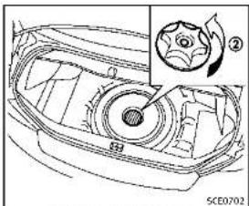
natural_image
Technical line drawing of a car head with a gear shift and fan assembly (no text or symbols)Sparetire(ifsoequipped)
Gettingthesparetire(ifso
equipped)andtools
Raisethetrunkfloorcover ①.
Removejackingtoolslocatedinsidethe
trunkasillustrated
Removethecap ② holdingthesparetire.
Jackingupthevehicleandremovingthedamagedtire
WARNING
●Nevergetunderthevehiclewhileitis supportedonlybythejack.Ifitis necessarytoworkunderthevehicle, supportitwithsafetystands.
- Useonlythejackprovidedwithyour vehicletoliftthevehicle.Donotusethe jackprovidedwithyourvehicleonother vehicles.Thejackisdesignedforlifting onlyyourvehicleduringatirechange.
■Usethecorrectjack-uppoints.Neveruse anyotherpartofthevehicleforjack support.
- Neverjackupthevehiclemorethan necessary.
- Neveruseblocksonorunderthejack.
■Donotstartorruntheenginewhile vehicleisonthejack,asitmaycause thevehicletomove.Thisisespecially true for vehicles with limited slip differentials.
- Do not allow passengers to stay in the vehicle while it is on the jack.
Carefullyreadthecautionlabelattachedto thejackbodyandthefollowinginstructions.
6-6 Incaseofemergency
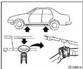
text_image
Diagram illustrating car safety system with downward arrows and a valve mechanism, labeled CE1089-AJack-uppoint
- Placethejackdirectlyunderthejack-up pointasillustratedsothetopofthe jackcontactsthevehicleatthejack-up point. Alignthejackheadbetween the twonotchesinthefrontortherearas shown. Alsofitthegrooveofthejack headbetweenenotenotchesasshown. Thejackshouldbeusedonlevelfirm ground.

text_image
Diagram showing car tire assembly process with tool and valve mechanism, labeled 'SC40504'-
Looseneachwheelnutoneortwoturns byturningcounterclockwisewiththe wheelnutwrench.Donotremovethe wheelnutsuntilthetireisoffthe ground.
-
Carefully raisethe vehicle until the tire clearsthe ground. Tolifthe vehicle, securely hold the jacklever and with both hands as shown above. Removethewheelnuts, and then removethetire.

Incaseofemergency6-7
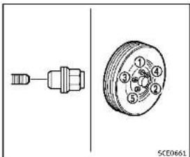
text_image
① ② ③ ④ ⑤ SCE0661Installingthesparetire
TheT-typesparetire(ifsoequipped)is designedforemergencyuse.(Seespecific instructionsundertheheading"Wheels andtires"(P.8-29).)
-
Cleananymudordirtfromthesurface betweenthewheelandhub.
-
Carefullyputthesparetireonand tightenthewheelnutsfingertight.
-
With the wheel nut wrench, tighten wheel nuts alternately and evenly in the sequence as illustrated (①, ②, ③, ④, ⑤) until they are tight.
6-8 Incaseofemergency
- Lowerthevehicleslowlyuntilthetire touchestheground.Then,withthe wheelnutwrench,tightenthewheel nutssecurelyinthesequenceas illustrated.Lowerthevehiclecompletely.
WARNING
- Incorrectwheelnutsorimproperlytightenedwheelnutscancausethewheeltobecome lose or come off. This could cause an accident.
- Donotuseoilorgreaseonthewheel studsornuts. This could cause them nuts tobecome loose.
- Retightenthewheelnutswhenthe vehiclehasbeendrivenfor600miles (1,000km)(alsoincasesofallattire, etc.).
- As soon as possible, tightent the wheelnut stothespecified torque withatorquewrench. Wheel nut tightening torque: 80 ft-lb (108 N·m)
The wheel nuts must be kept tightened to specification at all times. It
isrecommendedthatwheelnutsbe tightenedtospecificationsateach lubricationinterval.
- AdjusttirepressuretotheCOLD pressure.
COLDpressure:
Afterthevehiclehasbeenparked forthreehoursormoreordriven lessthan1mile(1.6km).
COLDtirepressuresareshownon theTireandLoadingInformation labelaffixedtothedriversidecenter pillar.

natural_image
Technical line drawing of a mechanical component with an arrow indicating direction (no text or symbols)-
Securelystoretheflattireandjacking equipmentinthevehicle.
-
Placethesparetirecover(ifso equipped)andthetrunkfloorcarpeting overthedamagedtire.
7.Closethetrunk.

WARNING
●Alwaysmakesurethatthesparetire(if soequipped)andjackingequipmentare properlysecuredafteruse.Suchitems canbecomedangerousprojectilesinan accidentorsuddenstop.
- The T-typesparetireandsmallsize sparetire(ifsoequipped)aredesigned foremergencyuse.Seespecificinstructionsundertheheading"Wheelsand tires"(P.8-29).

JUMPSTARTING
Tostartyourenginewithaboosterbattery, theinstructionsandprecautionsbelow mustbefollowed.

WARNING
- If done incorrectly, jump starting can lead to a battery explosion, resulting in severe injury or death. It could also damage your vehicle.
- Explosivehydrogengasisalwayspresentinthevicinityofthebattery.Keep allsparksandflamesawayfromthe battery.
- Donotallowbatteryfluidtocomeinto contactwitheyes,skin,clothingor paintedsurfaces.Batteryfluidisa corrosivesulphuricacidsolutionwhich cancausesevereburns.Ifthefluid shouldcomeintocontactwithanything, immediatelyflushthecontactedarea withwater.
- Keepthebatteryoutofthereachof children.
- Theboosterbatterymustberatedat12 volts.Useofanimproperlyratedbattery candamageyourvehicle.
- Whenever working on mearabattery, always wears suitable eyeprotectors (for example, goggles or industrials safety spectacles) and removerings, metal bands, or any other jewelry. Donotlean over the battery when jump starting.
- Donotattempttojumpstartafrozen battery.Itcouldexplodeandcause seriousinjury.
- Yourvehiclehasanautomaticengine coolingfan.Itcouldcomeonatanytime. Keephandsandotherobjectsawayfrom it.

text_image
A ①+ ②+ ③- ④- ①-②-③-④ B ①+ ④- #VF0107XWARNING
Alwaysfollowtheinstructionsbelow.Failure todosocouldresultindamagetothe chargingsystemandcausepersonalinjury.
- If the booster battery is in another vehicle (A), position the two vehicles (A) and (B) to bring their batteries into close proximity to each other.
Do not allow the two vehicles to touch. - Apply parking brake. Move the shift lever to the P (Park) position. Switch off
allunnecessaryelectricalsystems (light,heater,airconditioner,etc.).
-
Removeventcapsonthebattery(ifso equipped).Coverthebatterywitha firmlywrungoutmoistcloth to reduceexplosionhazard.
-
Connectjumpercablesinthesequence asillustrated( ① → ② → ③ → ④).
CAUTION
- Alwaysconnectpositive(+)topositive (+)andnegative(-)tobodyground(as illustrated)-nottothebattery.
- Makesurethejumpercablesdonot touchmovingpartsintheenginecompartmentandthatclampsdonotcontact anyothermetal.
5.Starttheengineoftheboostervehicle Ⓚ andletitrunforafewminutes.
- Keep the engines speed of the booster vehicle Ⓐ at about 2,000rpm, and start the engine of the vehicle being jump started Ⓑ.
CAUTION
Donotkeepthestartermotorengagedfor morethan10seconds.Iftheengineodes notstartrightaway,pushtheignition switchtotheOFFpositionandwait10 secondsbeforetryingagain.
-
After starting your engine, carefully disconnect then negative cable and then the positive cable (④ → ③ → ② → ①).
-
Replacetheventcaps(ifsoequipped). Besuretodisposeoftheclothusedto covertheventholesasitmaybe contaminatedwithcorrosiveacid.
-
Putthebatterycoveron.
PUSHSTARTING
Donotattempttostarttheengineby pushing.
CAUTION
●AutomaticTransmission(AT)models cannotbepush-startedortow-started. Attemptingtodosomaycausetransmissiondamage.
- Three-waycatalystequippedmodels shouldnotbestartedbypushingsince thethree-waycatalystmaybedamaged.
- Nevertrytostartthevehiclebytowing it;whentheenginestarts,theforward surgecouldcausethevehicletocollide withthetowvehicle.
IFYOURVEHICLEOVERHEATS

CAUTION
- Donotcontinuetodriveifyourvehicle overheats.Doingsocouldcauseengine damageoravehiclefire.
•Toavoidthedangerofbeingscalded, neverremovetheradiatorcapwhilethe engineisstillhot. Whentheradiatorcap isremoved, pressurizedhotwaterwill spurtout, possiblycausingserious injury.
- Donotopenthehoodifsteamiscoming out.
If your vehicle is overheating (indicated by an extremely high temperature gauge reading), or if you feel a lack of engine power, detect abnormal noise, etc., take the following steps:
-
Movethevehiclesafelyofftheroad, applytheparkingbrakeandmovethe shiftlevertotheP(Park)position. Donotstoptheengine.
-
Turnoff the climate control. Open all the windows, movethe heater or air condition at temperature control to maximum hot and fan control to high
6-12 Incaseofemergency
speed.
- If engine overheating is caused by climbing along hillonahotday, run the engine at a fastidle (approximately 1,500rpm) until the temperature gauge indication returnstonormal.
4.Getoutofthevehicle.Lookandlisten forsteamorcoolantescapingfromthe radiatorbeforeopeningthehood.(If steamorcoolantisescaping,turnoff theengine.)Donotopenthehood furtheruntilnosteamorcoolantcanbe seen.
- Opentheenginehood.

WARNING
If steamorwater is coming from the engine, stand cleartoprevent getting burned.
- Visuallycheckdrivebeltsfordamageor looseness. Also check if the cooling fan is running. Theradiator hoses and radiator should not leak water. If coolant is leaking or the cooling fan does not run, stop the engine.


WARNING
Becarefulnottoallowyourhands,hair, jewelryorclothingtocomeintocontact with,orgetcaughtin,enginebeltsorthe enginecoolingfan.Theenginecoolingfan canstartatanytime.
- After the engine cools down, check the coolant level in the reservoir tank with the engineer running. Add coolant to the reservoir tank if necessary. Have your vehiclerepaired at the nearest INFINIT retailer.
TOWINGYOURVEHICLE
Whentowingyourvehicle,allState(Pro- vincialinCanada)andlocalregulationsfor towingmustbefollowed.Incorrecttowing equipmentcouldaddageyourvehicle. Towinginstructionsareavailablefroman INFINITretailer. Localserviceoperatorsare familiarwiththeapplicablelawsand proceduresfortowing.Toassureproper towingandtopreventaccidentaldamage toyourvehicle.INFINITrecommendsthat youhaveaserviceoperatortowyour vehicle.Itisadvisabletohavetheservice operatorcarefullyreadthefollowingpre- cuations.

WARNING
●Neverrideinavehiclethatisbeing towed.
●Nevergetunderyourvehicleafterithas beenliftedbyatowtruck.

CAUTION
- Whentowing, makesurethatthetransmission, axles, steeringsystem and powertrain are in working condition. If any unit is damaged, dollies must be
used.
●Alwaysattachsafetylchainsbeforetow-
ing
Forinformationabouttowingyourvehicle behindarecreationalvehicle(RV),see "Flattowing"(P.9-19)ofthismanual.

Information Provided by DEALER
Incaseofemergency6-13

text_image
Diagram showing six car-related symbols: a tow truck, a flatbed truck, a flatbed car, a flatbed truck with crossed-out sign, and a cross symbol.Two-WheelDrive(2WD)models
TOWINGRECOMMENDEDBYINFINITI
Two-WheelDrive(2WD)models
INFINITIrecommendsthatyourvehiclebe towedwiththedriving(rear)wheelsoffthe groundorplacethevehicleonaflatbed truckasillustrated.

CAUTION
- Nevertowautomatictransmissionmodelswiththerearwheelsontheground orfourwheelsontheground(forwardor backward),asthismaycauseserious
andexpensivedamagetothetransmission.Ifitisnecessarytotowthevehicle withthefrontwheelsraised,alwaysuse towingdolliesundertherearwheels.
- Whentowing rear wheel drivemodels with the front wheels on the ground or ontowing dollies: Push the ignition switch to the ACC or ON position, and secure the steering wheel in a straight-ahead position with a rope or similar device.
6-14 Incaseofemergency
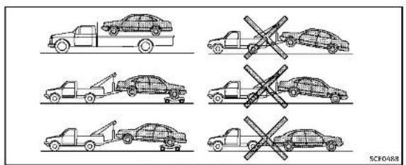
text_image
SCFO488All-WheelDrive(AWD)models
IntelligentAll-WheelDrive(AWD) models
INFINITrecommendsthattowingdolliesbe usedwhentowingyourvehicleorthe vehiclebeplacedonaflatbedtruckas illustrated.

CAUTION
NevertowIntelligentAWDmodelswithany ofthewheelsonthegroundasthismay causeseriousandexpensivedamagetothe powertrain.

DEALER
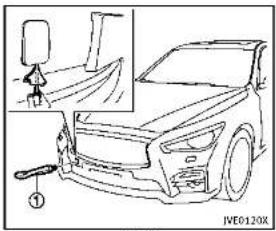
natural_image
Line drawing of a car front view with a small inset showing a person standing beside it (no text or symbols)Front
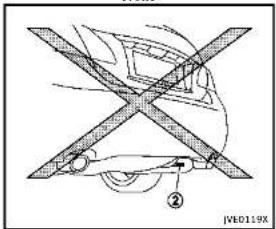
text_image
JB0119X ②Rear
Incaseofemergency6-15
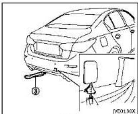
text_image
Technical diagram of a car showing front and side assembly with labeled parts and a valve mechanismRear
VEHICLERECOVERY(freeingastuck vehicle)

WARNING
• Standclearofastuckvehicle.
- Donotspinyourtiresathighspeed. This could cause them to explode and result in serious injury. Part of your vehicle could also overheat and bedamaged.
Pullingastuckvehicle
If your vehicle is stuckins and snow, mud, etc., use atowstrap or other device designed specifically for vehiclerecovery. Always follow the manufacturer's instructions for therecovery device.
Front:
-
Removethecoverusingasuitabletool.
-
Securely install the vehiclerecovery hook ① stored with jacking tools as illustrated. Attach the towstrap to the recovery hook. Makesure that the hook is properly secured in the original place after use.
Rear:
Donotusethetiedownhook ② for towingorvehiclerecovery.
Therearhook ③ isdesignedasthe recoveryhook.
Tousetherecoveryhook:
-
Removethecoverfromtherearbumper usingasuitabletool.
-
Securely install the recovery hook ③ (stored with jacking tools) to the attaching mount located on the rear bumper. DEALER
-
Makesurethattherecoveryhookis properlysecuredinitsstoragelocation afteruse.

CAUTION
- Towchainsorcablesmustbeattached onlytothevehiclerecoveryhooksor mainstructuralmembersofthevehicle. Otherwise,thevehiclebodywillbedamaged.
- Donotusethevehicletiedownstofree avehiclestuckinsand,snow,mud,etc.
- Nevertowavehicleusingthevehicletic downsorrecoveryhooks.
•Alwayspullthecablestraightoutfrom thefrontofthevehicle.Neverpullonthe vehicleatanangle.
- Pullingdevicesshouldberoutedsothey donottouchanypartofthesuspension, steering,brakeorcoolingsystems.
- Pullingdevicessuchasropesorcanvas strapsarenotrecommendedforusein vehicletowingorrecovery.
6-16 Incaseofemergency
Rockingastuckvehicle
If your vehicle is stuckins and, snow, mud,
etc., usethefollowingprocedure:
- TurnofftheVehicleDynamicControl
(VDC)system.
2.Makesuretheareainfrontandbehind
thevehicleisclearofobstructions.
3.Turnthesteeringwheelrightandleftto
clearanareaaroundthefronttires.
- Slowlyrockthevehicleforwardand
backward.
• ShiftbackandforthbetweenR
(Reverse)andD(Drive).
• Applytheacceleratoraslittleas
possibletomaintaintherocking
motion.
• Releasetheacceleratorpedalbefore
shiftingbetweenRandD.
• Donotspinthetiresabove35MPH
(55km/h).
- If the vehicle cannot be freed after a
fewtries,contactaprofessionaltowing
servicetoremovethevehicle.

Incaseofemergency6-17
MEMO
6-18 Incaseofemergency

Information Provided by: DEALER
7Appearanceandcare
Cleaningexterior....7-2
Washing....7-2 Waxing....7-2
Removingspots....7-3
Underbody....7-3
Glass....7-3 Wheels....7-3
Chromeparts....7-4
Tiredressing....7-4
Cleaninginterior....7-5
Airfresheners....7-5
Moonroofsunshade(ifsoequipped)....7-5
Floormats....7-6
Seatbelts....7-7 Corrosionprotection....7-7
Mostcommonfactorscontributingto
vehiclecorrosion....7-7
Environmental factors influencing
of corrosion....7-7
Toprotectyourvehiclefromcorrosion....7-8
CLEANINGEXTERIOR
Inordertomaintaintheappearanceof yourvehicle,itisimportanttotakeproper careofil.
Toprotectthepaintsurface, wash your vehicleassoonasyoucan:
●alterarainfalltopreventpossible damagefromacidrain
■afterdrivingoncoastalroads
- whencontaminantssuchassoot, bird droppings, treesap, metalparticles or bugsgetonthepaintsurface
-whendustormudbuildsuponthe surface
Whenever possible, store or park your vehicle insideagarage or in covered area.
Whenitisnecessarytoparkoutside,park inashadyareaorprotectthevehiclewith abodycover.
Becarefulnottoscratchthepaintsurface whenputtingonorremovingthebody cover.
WASHING
Washdirtoffthevehiclewithawetsponge andplentyofwater.Cleanthevehicle thoroughlyusingamildsoap,aspecial vehiclesoaporgeneralpurposedishwashingliquidmixedwithclean,lukewarm (neverhot)water.

CAUTION
- Donotusecarwashesthatuseacidin thedetergent. Somecarwashes, especiallybrushlessons, usesomeacidfor cleaning. Theacidmayreactwithsome plasticvehiclecomponents, causing themtocrack. Thiscouldaffecttheir appearance, andalsocouldcausethem nottofunctionproperly. Alwayscheck withyourcarwashtoconfirmthatacid isnotused.
■Donotwashthevehiclewithstrong householdsoap,strongchemicaldetergents,gasolineorsolvents.
- Donotwashthevehicleindirectsun-light or while the vehicle body is hot, as the surface may become water-spotted.
- Avoid using tight-napped or rough cloths, such as washing mitts. Care
mustbetakenwhenremovingcaked-on dirtorotherforeignsubstancesothe paintsurfacelsnotscratchedorda- maged.
Rinsethevehicleagainwithplentyofclean water.
Insideflanges, seamsandfoldsonthe doors, hatchesandhoodareparticularly vulnerabletotheeffectsofroadsalt. Therefore, theseareasmustberegularly cleaned. Makesurethatthedrainholesin theloweredgeofthedoorareopen. Spray waterunderthebodyandinthewheel wellstoloosenthedirtandwashaway roadsalt.
Avoidleavingwaterspotsonthepaint surfacebyusingadampchamoistodry thevehicle.
WAXING
Regularwaxingprotectsthepaintsurface andhelpsretainnewvehicleappearance. Polishingisrecommendedtoremovebuilt-upwaxresidueandtoavoidawweathered appearancebeforereapplyingwax. AnINFINITretailercanassistyouin choosingtheproperproduct.
- Waxyourvehicleonlyafterathorough washing.Followtheinstructionssuppliedwiththewax.
- Donotuseawaxcontainingany abrasives,cuttingcompoundsorcleanersthatmaydamagethevehicle finish.
Machinecompoundoraggressivepolishingonabasecoat/clearcoatpaintfinishmaydullthefinishorleaveswirlmarks.
REMOVINGSPOTS
Removetarandoilspots,industrialdust, insects,andtreesapasquicklyaspossible fromthepaintsurfacetoavoidlasting damageorstaining.Specialcleaning productsareavailableatanINFINITI retaileroranyautomotiveaccessory stores.
UNDERBODY
In areaswhereroadsaltisusedinwinter, theunderbodymustbecleanedregularly. Thiswillpreventdirtandsaltfrombuilding upandcausingtheaccelerationofcorrosionontheunderbodyandsuspension. Beforethewinterperiodandagaininthe spring,theundersealmustbechecked and,ifnecessary,re-treated.
GLASS
Useglasscleanertoremovesmokeand dustfilmfromtheglasssurfaces.Itis normalforglasstobecomecoatedwitha filmafterthevehicleisparkedinthehot sun.Glasscleanerandasoftclothwill easilyremovethisfilm.

CAUTION
Whencleaningtheinsideofthewindows, donotusesharp-edgedtools,abrasive cleanersorchlorine-baseddisinfectantcleaners.Theycoulddamagetheelectrical conductors,radioantennaelementsorrear windowdefrosterelements.
WHEELS
Washthewheelswhenwashingthevehicle tomaintaintheirappearance.
- Cleantheinnersideofthewheelswhen thewheelischangedortheunderside ofthevehicleiswashed.
- Inspect wheel rims regularly for dents or corrosion. Such damage may cause loss of pressure or poor seal at the tire bead.
- INFINITI recommendsthattheroad wheelsbewaxedtoprotectagainst roadsaltinareaswhereitisused duringwinter.

CAUTION
Donotuseabrasivecleanerswhenwashing thewheels.
Aluminumalloywheels
Washregularlywithaspongedampenedin amildsoapsolution,especiallyduring wintermonthsinareaswhereroadsaltis used.Saltcoulddiscolorthewheelsifnot removed.

CAUTION
Followthedirectionsbelowtoavoidstainingordiscoloringthewheels:
- Donotuseacleanerthatusesstrong acidoralkalicontentstocleanthe wheels.
- Donotapplywheelcleanerstothe wheelswhentheyarehot. Thewheel temperatureshouldbethesameas
ambienttemperature.
- Rinsethewheeltocompletelyremove thecleanerwithin15minutesafterthe cleanerisapplied.
Brightwheels(ifsoequipped)
Thebrightwheelsuseadifferentcoating processthantypicalaluminumalloywheel andtheyarenotplatedwheels. These wheelsareclear-coatedandrequirethe followingspecialcleaning.Theyshouldbe regularlywashedwithasoftsponge soakedaltofowater. Afterwashing withwater,wipecleanwithadry,softcloth anddrycompletely.Whenthereischemical orlirewax,ordirtsuchasanantilreeze agentonthesurface,washthemwith waterassoonaspossible.

CAUTION
- The surfaces of the wheels use a different coating process that typical aluminum alloy wheels. Do not use aluminum alloy wheel cleaners or abrasive cleaners to clean the wheels. Using such cleaners could damage the wheels surfaces.
- Donotuseanautomaticcarwashifthe vehicleisequippedwithbrightwheels. Thewheelcoatingmaybedamaged.
- Donotuseabrushtowashthewheelsif the vehicleisequipped withbright wheels. Thewheelcoating maybe damaged.
CHROMEPARTS
Cleanchromepartsregularlywithanon-abrasivechromepolishtomaintainthe finish.
TIREDRESSING
INFINITI does not recommend the use of tiredressings. Tire manufacturers apply a coating to the rest to help reduced coloration of the rubber. If tiredressings is applied to the retires, it may react with the coating and form compound. This compound may come off the rewhile driving and stain the vehicle paint.
If you choose to eat tired dressing, take the following precautions:
- Use a water-based tire dressing. The coating on the tire dissolves more easily with an oil-based tire dressing.
- Applyalightcoatoftiredressingto helppreventitfromenteringthetire tread/grooves(whereitwouldbedifficulttoremove).
- Wipeollexcesstiredressingusinga drytowel. Makesurethetiredressing iscompletelyremovedfromthetire tread/grooves.
- Allowthetiredressingtodryas recommendedbytiredressingmanufacturer.
7-4 Appearanceandcare
CLEANINGINTERIOR
Occasionallyremoveloosedustfromthe interiortrim,plasticpartsandseatsusing avacuumcleanerorsoftbristledbrush. Wipethevinylandleathersurfaceswitha clean,softclothdampenedinmildsoap solution,thenwipecleanwithadrysoft cloth.
Regularcareandcleaningisrequiredin ordertomaintaintheappearanceofthe leather.
Before using any fabric protector, read the manufacturer's recommendations. Some fabric protectors contain chemical that may stain or bleach these at material.
Useaclothdampenedonlywithwater,to cleanthemeterandgaugelens.

WARNING
Donotusewateroracidicle cleaners(hot steamcleaners)ontheseat.Thiscan damagetheseatoroccupantclassification sensors.Thiscanalsoaffecttheoperation oftheairbagsystemandresultinserious personalinjury.

CAUTION
●Neverusebenzine, thinner, orany similar material.
- Forcleaning, useasoftcloth, dampened withwater. Neverusearoughcloth, alcohol, benzine, thinneroranykindof solventorpapertowelwithachemical cleaningagent. They will scratchor caused discoloration to the lens.
- Donotsprayanyliquidsuchaswateron themeterlens.Sprayingliquidmay causethesystemtomalfunction.
■Smalldirtparticlescanbeabrasive and damagingtotheleathersurfacesand shouldberemovedpromptly.Donotuse saddlesoap,carwaxes,polishes,oils, cleaningfluids,solvents,detergentsor ammonia-basedcleanersastheymay damagetheleather'snaturaRfinish.
■Onlyusefabricprotectorsapprovedby INFINITI.
- Donotuseglassorplasticcleaneron meter or gauge lens covers. It may damage the lens cover.
AIRFRESHENERS
Mostairfreshenersuseasolventthat couldaffectthevehicleinterior.Ifyouuse anairfreshener,takethefollowingprecautions:
●Hanging-typeairfreshenerscancause permanentdiscolorationwhenthey contactvehicleinteriorsurfaces. Place theairfreshenerinalocationthat allowsittohangfreeandnotcontact aninteriorsurface.
- Liquid-typeairfreshenerstypicallyclip onthevents. Theseproductscancause immediatedamageanddiscoloration whenspilledoninteriorsurfaces.
Carefullyreadandfollowthemanufac-turer'sinstructionsbeforeusingairfresh-eners.
MOONROOFSUNSHADE(ifso equipped)
Themoonroofsunshadeismadefroma suedematerial.
Cleanthesunshadematerialasfollows:

Appearanceandcare7-5

CAUTION
Tohelppreventdamagingthesunshade whilecleaning:
- Donotrubthematerialwithacloth. Doingsocandamagethesurfaceofthe materialorcauseastaintospread.
●Neverusebenzine,thinneroranysimilar chemicaltocleanthesuede.Thismay discolorthesunshadeanddamagethe surface. - Cleanwaterbasedstainsbypatting the surfacewithacleansoftclothdampened inwarmwater.Pressacleandrycloth ontothesurfacetoremoveasmuch dampnessaspossibleandthenletair dry.
- Cleanoilbasedstainsbypatting the surface with a cleans soft cloth dampened in warm water. Pressacle and cry cloth onto the surfacetoremove as much dampness as possible and then let air dry.
FLOORMATS
WARNING
To avoid potential pedal interference that may result in a collision or injury:
- NEVERplaceaflormatontopof anotherfloormatinthedriverfront position.
■UseonlygenuineNISSANfloormats specificallydesignedforuseinyour vehiclemodel.SeeyourINFINITretailer formoreinformation.
•Properlypositionthematsinthefloor-wellusingthefloormatpositioningaid. See "Floormatpositioningaid" (P.7-6).
TheuseofINFINITifloormatscanextend thelifeofyourvehiclecarpetandmakeit easiertocleantheinterior.Matsshouldbe maintainedwithregularcleaningand replacediftheybecomeexcessivelyworn.
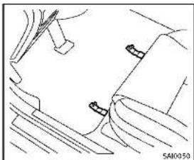
natural_image
Technical line drawing of a mechanical component with no visible text or symbolsFront(example)
Floormatpositioningaid Thismodelincludesfrontfloormatbracketstoactasfloormatpositioningaid.
INFINITIloormatshavebeenspecially designedforyourvehiclemodel.Thefront floormatshavegrommetholesinthem.To install,simplypositionthematbyplacing thefloormatbracketthroughthefloormat grommetholewhilecenteringthematin thefloorpancontour.
Periodicallychecktomakecertainthatthe matsareproperlypositioned.
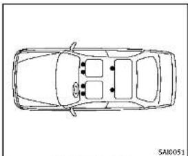
natural_image
Top-down line drawing of a car showing front and rear sections (no text or symbols)Bracketpositions
The illustrations show sthe location of the floormatbrackets.
SEATBELTS
Theseatbellscanbecleanedbywiping themwithaspongedampenedinamild soapsolution.Allowthebeltstodry completelybeforeusingthem.
See"Seatbelts"(P.1-12).

WARNING
Donotallowwetseatbeltstorollupinthe retractor.NEVERusebleach,dye,orchemi-
calsolventstocleantheseatbelts, since thesematerialsmayseverelyweakenthe seatbeltwebbing.

CORROSIONPROTECTION
MOSTCOMMONFACTORSCONTRIBUTINGTOVEHICLECORROSION
●The accumulation of moisture-retaining dirt and debris in body panel sections, cavities, and other areas.
● Damagelopainlandotherprotective coatingscausedbygravelandstone chipsorminortrafficaccidents.
ENVIRONMENTALFACTORSINFLU- ENCETHERATEOFCORROSION
Moisture
Accumulation of sand, dirt and water on the vehicle body underside can accelerate corrosion. Wet floor coverings will not dry completely inside the vehicle, and should be removed for drying to avoid floor panel corrosion.
Relativehumidity
Corrosionwillbeacceleratedinareas of highrelativehumidity,especiallythose areaswherethetemperaturesstayabove freezingwhereatmosphericpollutionexists,orwhereroadsaltisused.
Appearanceandcare7-7
Temperature
Atemperatureincreasewillacceleratethe rateofcorrosiontothosepartswhichare notwellventilated.
Airpollution
Industrial pollution, the presence of salt in the air in coastal areas, or heavy roads salt use will accelerate the corrosion process. Roads salt will also accelerate the integration of paints surfaces.
TOPROTECT YOURVEHICLEFROM CORROSION
■Washandwaxyourvehicleoftento keepthevehicleclean.
●Alwayscheckforminordamagetothe paintandrepairitassoonaspossible.
- Keepdrainholesatthebottomofthe doorsopentoavoidwateraccumulation.
- Checktheunderbodyforaccumulation of sand, dirtorsalt. If present, wash with waterassoonaspossible.
CAUTION
■NEVERremovedirt, sandorotherdebris from the passenger compartment by washing it out with a hose. Removedirt with vacuum cleaner.
- Neverallowwaterorotherliquidsto comeincontactwithelectroniccomponentsinsidethevehicleasthismay damagethem.
Chemicalsusedforroadsurfacedeicing areextremelycorrosive. Theyaccelerate corrosionanddeteriorationofunderbody componentssuchastheexhaustsystem, fuelandbrakelines,brakecables,floor panandfenders.
Inwinter, the underbody must be cleaned periodically.
For additional protection against trust and corrosion, which may be required in some areas, consult an INFINIT retailer.

7-8 Appearanceandcare
8Maintenanceanddo-it-yourself
Maintenancerequirement....8-2
Scheduledmaintenance....8-2
Generalmaintenance....8-2
Wheretogoforservice....8-2
Generalmaintenance....8-2
Explanationofmaintenanceitems......8-2
Maintenance precautions....8-5
Enginecompartmentchecklocations....8-6
VQ37VHRengine....8-6
Enginecoolingsystem....8-8
Checkingenginecoolantlevel....8-9
Changingenginecoolant....8-9
Engineoil....8-10
Checkingengineoillevel....8-10
Changingengineoilandfilter....8-10
Automatictransmissionfluid 8-12
wersteeringfluid(ifsoequipped)......8-13
Brakefluid 8-13
Windowwasherfluid 8-14
Battery 8-15
lumpstarting 8-16
Variablevoltagecontrolsystem.... 8-17
Drivebelts....8-17
Sparkplugs....8-18
Replacingsparkplugs....8-18
Aircleaner....8-19
Windshieldwiperblades....8-20
Cleaning....8-20
Replacing....8-20
Brakes....8-21
Self-adjustingbrakes....8-21
Brakepadwearwarning....8-21
Fuses 8-22
Enginecompartment......8-22
Passengercompartment 8-23
IntelligentKeybatteryreplacement....8-24
Lights....8-26
Exteriorandinteriorlights....8-27
Wheelsandtires....8-29
Tirepressure 8-29
Tirelabeling 8-32
Typesoftires 8-34
Tirechains 8-36
Changingwheelsandtires....8-37
MAINTENANCEREQUIREMENT
Someday-to-dayandregularmaintenance isessentialtomaintainyourvehiclegood mechanicalcondition,aswellsatsemissionandengineperformance. Itistheowner'sresponsibilitytomake surethatthescheduledmaintenance,as wellasgeneralmaintenance,isperformed. Asthevehicleowner,youaretheonlyone whocanensurethatyourvehiclereceives thepropermaintenance.Youareavitallink inthemaintenancechain.
Foryourconvenience, bothrequired and optional scheduled maintenance items are described and listed in your "INFINITI Service and Maintenance Guide". You must refer to that guideto ensure that necessary maintenance is performed by your vehicle at regular intervals.
GENERALMAINTENANCE
Generalmaintenanceincludesthoseitems whichshouldbecheckedduringnormal day-to-dayoperation. Theyareessentialfor propervehicleoperation.Itisyourresponsibilitytoperformtheseproceduresregularlyasprescribed.
Performinggeneralmaintenancechecks
requiresminimalmechanicalskillandonly afewgeneralautomotivetools.
These checks or inspections can be done by yourself, a qualified technician, if you prefer, an INFINIT retailer.
WHERETOGOFORSERVICE
Ifmaintenanceserviceisrequiredoryour vehicleappearstomalfunction,havethe systemscheckedandserviced by an INFINITretailer.
INFINITtechniciansarewell-trainedspecialistsandarekeptuptodatewiththe latestserviceinformationthroughtechnicalbulletins,servicetips,andin-retailership information systems. They are completelyqualifiedtoworkonINFINITI vehiclesbeforeworkbegins.
You can be confident that an INFINITI retailer's serviced department performs the best job to meet them, maintaining an requirement on your vehicle.

GENERALMAINTENANCE
Duringthenormalday-to-dayoperation of the vehicle, generalmaintenances should be performed regularly as prescribed in this section. If you detect any unusual sounds, vibrations or smell, be sureto check for the cause or have an INFINITI retailer do it promptly. In addition, you should notify an INFINITI retailer if you think that repairs are required.
When performing any checks or maintenance work, see "Maintenance precautions" (P.8-5).
EXPLANATIONOFMAINTENANCE ITEMS
Additional information on the following itemswith“*”isfoundlaterinthis section.
Outsidethevehicle
Themaintenanceitemslistedhereshould beperformedfromtimetotime,unless otherwise specified.
Doors and engine hood: Check that all doorsandtheenginehood, operate properly. Also ensure that all latcheslock securely. Lubricate hinges, latches, latch pins, rollersandlinksifnecessary. Make sure that these secondary latch keeps the hood from opening when the primary latch
8-2 Maintenance and do-it-yourself
isreleased.
Whendrivinginareasusingroadsaltor othercorrosivematerials, checklubrication frequently.
Lights*:Cleantheheadlightsonaregular basis.Makesurethattheheadlights,stop lights,taillights,turnsignallights,and otherlightsarealloperatingproperlyand installedsecurely.Alsocheckheadlight aim.
Roadwheelnuts(lugnuts)*:Whencheckingthetires,makesurenowheelnutsare missing,andcheckforanyloosewheel nuts.Tightenifnecessary.
Tirerotation*: Tiresshouldberotated every 5,000 miles (8,000 km).
Tires*:Checkthepressurewithagauge oftenandalwayspriortolongdistance trips.Ifnecessary,adjustthepressurein alltires,includingthespare,tothe pressurespecified.Checkcarefullyfor damage,cutsorexcessivewear.
TirePressureMonitoringSystem(TPMS) transmittercomponents:ReplacetheTPMS transmittergrommetseal,valvecoreand capwhenthetiresarereplaceddueto wearorage.
Tire, wheelalignmentandbalance: If the
vehicles should pull to either sidewhile driving on a straight handle road, or if you detect one venorab normal tire wear, therem maybe needed for wheel alignment. If the steering wheel or seat vibrates at normal highways speeds, wheel balancing may be needed.
For additional information regarding tires, refer to "Important Tire Safety Information" (US) or "Tire Safety Information" (Canada) in the INFINITE Warranty Information Booklet.
Windshield: Cleanthewindshieldona regularbasis. Checkthewindshieldat leasteverysixmonthsforcracksorother damage. Haveamagedwindshield repairedbyaqualifiedrepairfacility. Windshieldwiperblades*:Checkfor cracksorweariftheydonotwipeproperly.
Insidethevehicle
Themaintenanceitemslistedhereshould becheckedonaregularbasis,suchas whenperformingperiodicmaintenance, cleaning the vehicle, etc.
Accelerator pedal: Check the pedal for smooth operation and make sure the pedal does not catch or require uneven effort.
Keepthefloormatawayfromthepedal.
AutomatictransmissionP(Park)mechanism:Onafairlysteephill,checkthatyour vehicleisheldsecurelywiththeshiftlever intheP(Park)positionwithoutapplying anybrakes.
Brakepedal: Checkthepedalforsmooth operation. If the brakepedalsuddenly goes down further than normal, the pedal feels spongy or the vehicle seem st o take longert o stop, see an INFINIT retailer immediately. Keep the floormataway from the pedal.
Brakes: Check that the brakes donot pull the vehicle to onesidewhen applied.
Parkingbrake:Checktheparkingbrake operationregularly.Thevehicleshouldbe securelyheldonafairlysteephillwithonly theparkingbrakeapplied.Iftheparking brakeneedsadjusted,seenANFINITI retailer.
Seatbelts: Check that all part of these seat beltsystem (forexample, buckles, anchors, adjuster and retractors) operate properly and smoothly, and are installed securely. Check the belt webbing for cuts, fraying, wearordamage.
Seats: Checkseatpositioncontrolssuchas
Maintenanceanddo-it-yourself8-3
seatadjusters, seatbackrecliner, etc. to ensure they operates smoothly and that all latches lock securely every position. Check that the head restraints move up and down smoothly and that the locks (if so equipped) hold securely in all latched positions.
Steeringwheel: Checkforchangesinthe steeringconditions, such as excessive free play, hardsteeringorstrangenoises.
Warninglightsandchimes: Makesurethat allwaminglightsandchimesareoperating properly.
Windshielddefroster:Checkthattheair comesoutofthedefrosteroutletsproperly andinsufficientquantitywhenoperating theheaterorairconditioner.
Windshieldwiperandwasher*:Checkthat thewipersandwasheroperateproperly and thatthewipersdonotstreak.
Underthehoodandvehicle
Themaintenanceitemslistedhereshould becheckedperiodically(forexample,each timeyouchecktheengineoilorrefuel).
Battery*: Checkthefluidlevelineachcell. It should be between the MAX and MIN lines. Vehicles operated in hightempera-
turesorundersevereconditionrequire frequentchecksofthebatteryfluidlevel.
Careshouldbetakentoavoidsituations thatcanleadtopotentialbatterydischargeandpotentialno-startconditions suchas:
-
Installationorextendeduseofelectronicaccessoriesthatconsumebattery powerwhentheengineisnotrunning (Phonechargers,GPS,DVDplayers, etc.)
-
Vehicle is not driven regularly and/or only drivenshort distances.
In these cases, the battery may need to be charged to maintain battery health.
Brakefluidlevel*: Makesurethatthe brakefluidlevelisbetweentheMAXand MINlinesonthereservoir.
Enginecoolantlevel*:Checkthecoolant levelwhentheengineiscold.
Enginedrivebelts*: Makesurethatnobelt isfrayed, worn, crackedorily.
Engine oil level*: Check the level after parking the vehicle on a level spot and turning off the engine. Wait more than 15 minutes for the oil to drain back into the oil
pan.
Exhaustsystem: Makesurethereareno loosesupports, cracksorholes. If the soundoftheexhaustseemsunusualor thereisasmellofexhaustfumes, im- mediatelyhavetheexhaustsystemin- spectedbyanINFINITIretailer. (See "Precautionswhenstartinganddriving" (P.5-3.)
Fluidleaks:Checkunderthevehiclefor fuel,oil,waterorotherfluidleaksafterthe vehiclehasbeenparkedforawhile.Water drippingfromtheairconditionerafteruse isnormal.Ifyoushouldnoticecanyleaksor ifgasolinefumesareevident,checkforthe causeandhaveitcorrectedimmediately.
Powersteeringfluidlevel* andlines: Checkthelevelwhenthefluidiscold, withtheengineoff. Checkthelinesfor properattachment, leaks, cracks, etc.
Radiatorandhoses:Checkthelrontofthe radiatorandcleanoffanydirt,insects, leaves,etc.,thatmayhaveaccumulated. Makesurethehoseshavenocracks, deformation,rotorlooseconnections.
Underbody:Theunderbodyisfrequently exposedtocorrosivesubstancessuchas thoseusedonicyroadsortocontroldust.
MAINTENANCEPRECAUTIONS
It's very important to remove these substances, otherwise must will form the floorpan, frame, fuel lines and around the exhaust system. At the end of winter, the underbody should be thoroughly flushed with plain water, being carefully clean those areas where the mud and dirt may accumulate. For additional information, see "Cleaning exterior" (P.7-2). Windshield washer fluid: Check that there is adequate fluid in the reservoir.
When performing any inspection or maintenance work, you have already done a care to prevent serious accident in injury to yourself for damage to the vehicle. The following are general precautions which should be closely observed.

WARNING
■Parkthevehicleonalevelsurface,apply theparkingbrakesecurelyandblockthe wheelstopreventthevehiclefrom moving.MovetheshiftlevertoP(Park).
- BesuretheignitionswitchisintheOFF orLOCKpositionwhenperformingany partsreplacementorrepairs.
- Neverconnectordisconnectthebattery oranytransistorizedcomponentwhile theignitionswitchisintheONposition.
- Neverleavetheengineorautomatic transmissionrelatedcomponentharnessesdisconnectedwhiletheignition switchisintheONposition.
- If you must work with the engine running, keep your hands, clothing, hair and tools away from moving fans, belts and any other moving parts.
- It is advisable to secure or remove any loose clothing and remove any jewelry, such as rings, watches, etc. before working on your vehicle.
•Alwaysweareyeprotectionwhenever youworkonyourvehicle. - If you must run the engine in an enclosed spaces such as a garage, be sure there is proper ventilation for exhaust gas to escape.
●Nevergetunderthevehiclewhileitis supportedonlybyajack.Ifitis necessarytoworkunderthevehicle, supportitwithsafetystands. - Keepsmokingmaterials, flameand sparksawayfromfueltankandthe battery.
-Yourvehicleisequippedwithanautomaticenginecoolingfan.Itmaycomeon atanytimewithoutwarning,evenifthe ignitionkeyisintheOffpositionand theengineisnotrunning.Toavoid injury,alwaysdisconnectthenegative batterycablebeforeworkingnearthe fan. - The fuelfilter or fuelliness should be serviced by an INFINIT retailer because the fuellines are under high pressure
Maintenanceanddo-it-yourself
ENGINECOMPARTMENTCHECKLOCATIONS
evenwhentheengineisoff.

CAUTION
- Donotworkunderthehoodwhilethe engineshot.Turntheengineoffand waltuntilcoolsdown.
- Avoiddirectcontactwithusedengineoil andcoolant.Improperlydisposedengine oil,coolant,and/orothervehiclefluids candamagetheenvironment.Always conformtolocalregulationsfordisposal ofvehiclefluid.
This"8.Maintenanceanddo-it-yourself" sectiongivesinstructionsregardingonly thoseitemswhicharerelativelyeasyforan ownertoperform.
AgenuineINFINITIServiceManualisalso available.(See"Owner'sManual/Service Manualorderinformation"(P.9-23).)
Youshouldbeawarethatincompleteor improperservicingmayresultinoperating difficultiesorexcessiveemissions,and couldaffectyourwarrantycoverage.Ifin doubtaboutanyservicing,werecommend thatitbedonebyanINFINITiretaller.
8-6 Maintenance and do-it-yourself
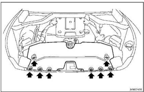
natural_image
Top-down technical diagram of a car engine bay with mounting flanges and directional arrows indicating assembly or maintenance points (no text labels)VQ37VHRENGINE
Toremovetheenginecompartmentcover, unhook the clips located as illustrated.


text_image
JVM0250X1.Battery
2. Engineoilfillercap
3.Brakefluidreservoir
4.Powersteeringfluidreservoir(ifso
equipped)
5.Aircleaner
6.Radiatorfillercap
7Enginecoolantreservoir
8Engineoildipstick
9Engine drive belt location
10Fuse/fusiblelinkholder
11 Windowwasherfluidreservoir

Maintenanceanddo-it-yourself8-7
ENGINECOOLINGSYSTEM
Theenginecoolingsystemisfilledatthe factorywithapre-dilutedmixtureof50% GenuineNISSANLonglifeAntifreeze/Coolant(blue)and50%watertoprovideyear-roundanti-freezeandcoolantprotection. Theanti-freezesolutioncontainsrustand corrosioninhibitors.Additionalengine coolingsystemadditivesarenotnecessary.

WARNING
- Neverremovetheradiatorcapwhenthe engineshot.Waltuntiltheengineand radiatorcooldown.Seriousburnscould becausedbyhighpressurefluidescapingfromtheradiator.Seeprecautionsin "Ifyourvehicleoverheats"(P.6-12)of thismanual.
•Theradiatorisequippedwithapressure typeradiatorcap.Topreventengine damage,useonlyagenuineNISSAN radiatorcap.

CAUTION
●Neveruseanycoolingsystemadditives suchasradiatorsealer.Additivesmay
clogthecoolingsystemandcause damagetotheengine,transmission and/orcoolingsystem.
Whenaddingorreplacingcoolant, be suretouseonlyGenuineNISSANLong LifeAntifreeze/Coolant(blue)orequival- ent.GenuineNISSANLongLifeAnti- freeze/Coolant(blue)ispre-dilutedto provideantifreezeprotectionto-34°F (-37°C). If additional freeze protection is neededduetoweatherwhereyou operateyourvehicle,add Genuine NISSANLongLifeAntifreeze/Coolant ( blue)concentratefollowingthedirec- tionsonthecontainer.ifanequivalent coolant other than Genuine NISSAN Long LifeAntifreeze/Coolant(blue)isused, follow the coolant manufacture's instruc- tionstomalntalminlimumantifreeze protection to -34°F (-37°C). The use of other typesof coolant solutionsother than GenuineNISSANLongLifeAnti- freeze/Coolant(blue)orequivalentmay damagetheenginecoolingsystem.
●Thelifeexpectancyofthefactory-fill coolant is 105,000 miles (168,000 km) or 7 years. Mixing any other type of coolant other than Genuine NISSAN Long Life Antifreeze/Coolant (blue), including
GenuineNISSANLongLifeAntifreeze/Coolant(green),ortheuseofnon-distilledwaterwillreducethelife expectancyofthefactory-fillcoolant. RefertotheINFINITIServiceandMaintenanceGuideformoredetails.
8-8 Maintenance and do-it-yourself
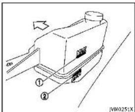
text_image
Technical diagram of a mechanical device with labeled parts and directional arrowsCHECKINGENGINECOOLANTLEVEL
CheckthecoolantlevelInthereservoir
whentheengineiscold.lthecoolant levelishelowMIN. ① apenthereservair
levelsbelowMIN ②,openthereservon tankcanandaddcoolantuntotheMAX
tankcapanducoolantuptothemAX level.Ifthereservoirtankisempty.check
thecoolantvelintheradiatorwhenthe
engineiscold.Ifthereisinsufficient
coolantintheradiator,filltheradiator
withcoolantuptotherilleropeningand
absaddittothereservortankuptothe MAXlevel ①.
Tightentheransecurelyafteradding
enginecoolant.
Ifthecoolingsystemrequirescoolant
frequently, haveitcheckedbyanINFINITI
retailer.
CHANGINGENGINECOOLANT
Majorcoolingsystemrepairsshouldbe
performedbyanINFINITretailer.The
serviceprocedurescanbefoundinthe
appropriateINFINITServiceManual
Improperservicingcanresultinreduced
heaterperformanceandengineoverheat-
ing.

WARNING
•Toavoidthedangerofbeingscalded, neverchangethecoolantwhenthe engineishot.
- Neverremovetheradiatorcapwhenthe engineishot.Seriousburnscouldbe causedbyhighpressurefluidescaping fromtheradiator.
- Avoiddirectskincontactwithused coolant.Ifskincontactismade,wash thoroughly with soap or hand cleaner as soon as possible.
- Keep coolant out of reach of children and pets.
Enginecoolantmustbedisposedof
properly.Checkyourlocalregulations.
ENGINEOIL

text_image
Technical diagram showing vehicle component assembly with numbered parts and directional arrow indicating motionCHECKINGENGINEOILLEVEL
- Parkthevehicleonalevelsurface and applytheparkingbrake.
- Runtheengineuntilreachesoperatingtemperature.
- Turnofftheengine.Waltmorethan15 minutesfortheoiltodrainbackinto theoilpan.
- Removethedipstickandwipeitclean. Reinsertitalltheway.
- Removethedipstickagainandcheck theoillevel.itshouldbewithinthe range ①. Iftheoillevelisbelow removetheoilfillercapandpour
8-10 Maintenance and do-it-yourself
recommendedoilthroughtheopening. Donotoverfill ③.
- Recheckoillevelwiththedipstick. Itisnormaltoaddsomeoilbetweenoil maintenanceintervalsorduringthebreak-inperiod,dependingontheseverlty of operatingconditions.
CAUTION
Oillevelshouldbecheckedregularly. Operatingtheenginewithaninsufficient amountofoilcandamagetheengine,and suchdamageisnotcoveredbywarranty.
②.

CHANGINGENGINEOILANDFILTER
Vehicleset-up
- Parkthevehicleonalevelsurface and apply the parking brake.
- Runtheengineuntilreachesoperatingtemperature.
3.Turntheengineoffandwaitmorethan 15minutes. - Raise and support the vehicle using a suitable floor jack and safety jack stands.
- Placethesafetyjackstandsunder thevehiclejack-uppoints.
• Asuitableadaptersshouldbeattachedtothejackstandsaddle.
- Removetheplasticengineundercover. • Removethesmallplasticclipatthe centerpointoftheundercover.
- Thenremovetheotherboltsthat holdtheundercoverinplace.
CAUTION
Makesurethecorrectliftingandsupport pointsareusedtoavoidvehicledamage.
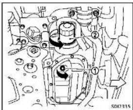
natural_image
Mechanical assembly diagram showing internal components and motion indicators (no readable text or symbols)2WDmodels
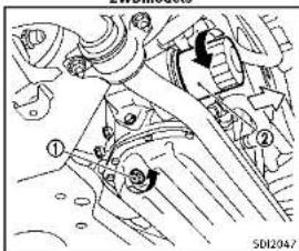
text_image
Technical diagram of a mechanical assembly with numbered components and reference number SD12047AWDmodels
Engineoilandfilter
-
Placealargedrainpanunderthedrain plug.
-
Removetheoilfillercap.
-
Removethedrainplug ① with a wrench and completely drain the oil.

CAUTION
Becarefulnottoburnyourself,asthe engineoilishot.
- Wasteoilmustbedisposedof properly.
- Checkyourlocalregulations.
4.(Performsteps4to7onlywhenthe engineoilfilterchangeisneeded.) Loosentheoilfilter ② withanoilfilter wrench.Removetheoilfilterbyturning itbyhand.
- Wipetheengineoilfiltermounting surface with a cleanrag.

CAUTION
Be sure to remove any old rubber gasket remaining on the mounting surface of the
engine.Failuretodosocouldleadtoengine damage.
6.Coatthegasketonthenewfilterwith cleanengineoil.
- Screwintheoilfilterclockwiseuntila slightresistanceisfelt,thenlighten additionallymorethan2/3turn.
Oilfiltertighteningtorque: 11to15ft-lb (14.7to20.5N·m)
- Cleanandre-installthedrainplugwith anewwasher.Securelytightenthe drainplugwithawrench.
Drainplugtighteningtorque: 22to29ft-lb (29to39N·m)
Donotuseexcessiveforce.
- Refillenginewithrecommendedoiland installtheoilfillercapse securely. See "Capacitiesandrecommended fuel/lubricants"(P.9-2)fordrainand refillcapacity.Thedrainandrefill capacitydependsontheoiltemperatureanddraintime.Usethesespecificationsforreferenceonly.Alwaysuse thedlipsticktodeterminetheproper
Maintenanceanddo-it-yourself8-11
AUTOMATICTRANSMISSIONFLUID
amountofoilintheengine.
-
Start the engine and check for leakage around the drain plug and the oil filter. Correct as required.
-
Turntheengineoffandwaitmorethan 15minutes. Checktheoillevelwiththe dipstick.Addengineoilifnecessary.
Aftertheoperation
- Install the engine undercover into position asthe following steps.
a.Pullthecenterofthesmallplastic clipout.
b. Hold the engine undercover into position.
c. Insert theclip through the under-cover into the hole in the frame, then push the center of the clip into lock the clip in place.
d. install the other boltsthathold the undercover in place. Becareful not to strip the bolts or over-tighten them.
-
Lowerthevehiclecarefullytothe ground.
-
Disposeofwasteoilandfilterproperly.
8-12 Maintenance and do-it-yourself
WARNING
•Prolongedandrepeatedcontactwith usedengineollmaycauseskincancer.
- Trytoavoiddirectskincontactwithused oil. If skin contact is made, wash thoroughly with soaporhandcleaner as soon as possible.
- Keepusedengineoiloutofreachof children.
Whencheckingorreplacementisrequired, werecommendanINFINITretailerfor servicing.
CAUTION
•UseonlyGenuineNISSANMaticSATF. Donotmixwithotherfluids.
- Using automatic transmission fluid other than Genuine NISSANMatic SATF will cause deterioration and drive ability and automatic transmission durability, and may damage the automatic transmission, which is not covered by the INFINITE new vehicle limited warranty.

POWERSTEERINGFLUID(ifsoequipped)
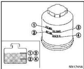
text_image
① ② ③ ④ ①③ ②④ 501765ACheckthefluidlevelinthereservoir.
Thefluidlevelshouldbecheckedusingthe HOTrange( ①:HOTMAX., ②:HOTMIN.) atfluidtemperaturesof122to176 F(50 to80°C)orusingtheCOLDrange( ③: COLDMAX., ④:COLDMIN.)atfluid temperatures of 32 to 86°F (0 to 30°C).
IfthefluidisbelowtheMINline,add GenuineNISSANPSForequivalent.Removethecapandfillthroughtheopening.
BRAKEFLUID
CAUTION
- Donotoverfill - UseGenuineNISSANPSForequivalent.
For further brake fluid information, see "Capacities and recommended fuel/lubricants" (P.9-2) of this manual.
WARNING
- Useonlynewfluidfromasealed container.Old,inferiorontaminated fluidmaydamagethebrakesystem. The useofimproperfluidscandamagethe brakesystemandaffectthevehicle's stoppingability. - Cleanthefillercapbeforeremoving. - Brakefluidispoisonousandshouldbe storedcarefullyinmarkedcontainersout ofthereachofchildren.
CAUTION
Donotspillthefluidonpaintedsurfaces. Thiswilldamagethepaint.Iffluidisspilled, washthesurfacewithwater.

Maintenanceanddo-it-yourself
WINDOWWASHERFLUID

text_image
Diagram of a car engine showing internal components and a labeled component with parts ① and ②, including a zoomed-in view.Checkthefluidlevelinthereservoir.Ifthe fluidisbelowtheMINline ② orthebrake warninglightcomeson,addGenuine NISSANSuperHeavyDutyBrakeFluidor equivalentDOT3fluiduptotheMAXline ①. Iffluidmustbeaddedfrequently,the systemshouldbecheckedbyanINFINITI retailer.

text_image
JVM0253XWARNING
Antifreezeispoisonousandshouldbe storedcarefullyinmarkedcontainersout ofthereachofchildren.
Fillthewindowwasherfluidreservoir periodically.Addwindowwasherfluid whenthelowwindowwasherfluidwarning appearsinthevehicleinformationdisplay. To fill the window washer fluid reservoir, lift the cap off the reservoir and pour the window washer fluid into the reservoir opening.
Tocheckthewindowwasherfluidlevel, useyourfingertoplugthehole (of the cap/tubeassembly, thenremoveitfrom thereservoir.Ifthereisnofluidinthetube, addfluid. Addawashersolventtothewasherfor bettercleaning.Inthewinterseason, addo windshieldwasherantifreeze. Follow the manufacturer'sinstructionsforthemixture ratio. Refillthereservoirmorefrequentlywhen drivingconditionsrequireanincreased amountofwindowwasherfluid. RecommendedfluidisGenuineNISSAN WindshieldWasherConcentrateCleaner& Antifreezeequivalent.
CAUTION
- Donotsubstituteengineanti-freeze coolantforwindowwashersolution.This mayresultindamagetothepaint. - Donotfillthewindowwasherreservoir withwasherfluidconcentratesatfull strength.Somemethylalcoholbased washerfluidconcentratesmaypermanentlystainthegrilleispilledwhile fillingthewindowwasherreservoir.
8-14 Maintenance and do-it-yourself
BATTERY
- Pre-mixwasherfluidconcentrateswith watertothemanufacturer's recommended levelsbeforepouringthefluid intothewindowwasherreservoir.Donot usethewindowwasherreservoirtomix thewasherfluidconcentrateandwater.
- Keepthebatterysurfacecleananddry. Cleanthebatterywithasolutionof bakingsodaandwater.
●Makecertaintheterminalconnections arecleanandsecurelytightened.
- If the vehicle is not to be used for 30 days longer, disconnect then negative (-) battery terminal cable to prevent discharging it.
NOTE:
Careshouldbetakentoavoidsituations thatcanleadtopotentialbatterydischargeandpotentialno-startconditions suchas:
-
Installationorextendeduseofelectronicaccessoriesthatconsumebattery powerwhentheengineisnotrunning (Phonechargers,GPS,DVDplayers, etc.)
-
Vehicle is not driven regularly and/or only drivenshort distances.
In these cases, the battery may need to be charged to maintain battery health.

WARNING
- Do not expose the battery to flames or electrical sparks. Hydrogen gas gener-
atedbythebatteryisexplosive.Donot allowbatteryfluidtocontactyourskin, eyes,fabrics,orpalntedsurfaces.After touchingabatteryorbatterycap,donot touchorrubyyoueyes.Thoroughlywash yourhands.Iftheacidcontactsyour eyes,skinorclothing,immediatelyflush withwaterforleast15minutesand seekmedicalattention.
- Donotoperatethevehicleifthefluidin thebatteryislow.Lowbatteryfluidcan causeahigherloadonthebatterywhich cangenerateheat,reducebatterylife, andinsomecasesleadtoanexplosion.
- When working on or near a battery, always wears suitable eyeprotection and remove all jewelry.
- Batteryposts,terminalsandrelated accessoriescontainleadandleadcompounds.Washhandsafterhandling.
- Keepthebatteryoutofthereachof children.
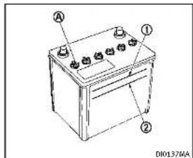
text_image
A ① ② D10137MACheckthefluidlevelineachcell(Remove thebatterycoverifitisnecessary).It shouldbebetweentheUPPERLEVEL andLOWERLEVEL ② lines. Ifitisnecessarytoaddfluid,addonly distilledwatertobringtheleveltothe indicatorineachfilleropening.Donot overfill.

text_image
① ② SDH-ABOC1.Removethecellplugs Ⓐ.
2.AdddistilledwateruptotheUPPER LEVEL ① line. Ifthesideofthebatteryisnotclear, checkthedistilledwaterlevelby lookingdirectlyabovethecell; the condition ① indicatesOKandthe conditions ② needsmoretobeadded.
- Tightencellplugs (A).
Vehiclesoperatedinhightemperaturesor under severe conditions require frequent checks of the battery fluid level.

JUMPSTARTING
Ifjumpstartingisnecessary,see"Jump starting"(P.6-9).Iftheenginedoesnot startbyjumpstarting,thebatterymay havetobereplaced.ContactanINFINITI retailer.
8-16 Maintenance and do-it-yourself
- Use electrical accessories with the engineer running to avoid discharging the vehicle battery.
The variable voltage control system measures the amount of electrical discharge from the battery and control voltage generated by the generator.

text_image
1 2 5 4 SDP119TypeA
- Powersteeringfluidpump
2.Alternator
3.Crankshaftpulley
4.Airconditionercompressor
5.Drivebellauto-tensioner
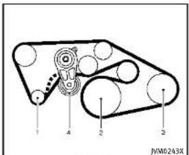
text_image
1 2 3 4 JVM0243XTypeB
- Alternator
2.Crankshaftpulley - Airconditionercompressor
4.Drivebeltauto-tensioner

WARNING
BesuretheignitionswitchisintheOFFor
LOCKpositionbeforeservicingdrivebelts.
Theenginecouldrotateunexpectedly
- Visually inspect each belt for sign of unusual wear, cuts, fraying or looseness. If the belt is in poor condition or
Maintenanceanddo-it-yourself8-17
SPARKPLUGS
loose, haveitreplacedoradjustedby anINFINITretailer.
- Havethebelts checked regularly for condition and tension in accordance with them maintenances schedule in your "INFINITIServiceandMaintenance Guide".
WARNING
Besuretheengineandtheignitionswitch areoffandthattheparkingbrakeis engagedsecurely.
CAUTION
Besuretousethecorrectsocketto remove thesparkplugs.Anincorrectsocketcan damagethesparkplugs.

text_image
5012020REPLACINGSPARKPLUGS
Ifreplacementisrequired,seeanINFINITI retailerforservicing.
Iridium-tippedsparkplugs
Itisnotnecessarytoreplacetheiridium-tippedsparkplugsasfrequentlyasthe conventionaltypesparkplugssincethey willlastmuchlonger.Followthemain- tenanceschedulein"INFINITIServiceand MaintenanceGuide",butdonotreuse thembycleaningorregapping.

8-18 Maintenance and do-it-yourself
Alwaysreplacesparkplugswithrecommendedorequivalentones.
AIRCLEANER
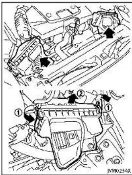
text_image
Technical diagram showing engine components with numbered annotations and directional arrows indicating assembly or movement.Removetheretainers ① asillustrated and pullout the filter element ②. The filter elements should not be cleaned and reused. Replace it according to the maintenance intervals. See "INFINITI Service and Maintenance Guide" for maintenance intervals. When replacing the filter
wipetheinsideoftheaircleanerhousing andthecoverwithadampcloth.

WARNING
- Operating the engine with the air cleaner removed can cause you or others to be burned. The air cleaner not only cleanstheair, it stops flame if the engine back fires. If it isn't there, and the engine back fires, you could be burned. Donot drivewith the air cleaner removed, and be careful when working on the engine with the air cleaner removed.
- Neverpourfuellintothethrottlebodyor attempttostarttheenginewiththeair cleanerremoved.Doingsocouldresult inseriousinjury.
Maintenanceanddo-it-yourself8-19
WINDSHIELDWIPERBLADES
CLEANING
If your windshield is not clear after using the windshield washer or if a wiper blade chatters when running, wax or other material may be on the blade or windshield.
Cleantheoutsideofthewindshieldwitha washersolutionoramilddetergent.Your windshielddiscleanifbeadsdonotform whenrinsingwithclearwater.
Cleaneachbladebywipingitwithacloth soakedinawashersolutionoramild detergent. Thenrinsethebladewithclear water. If your windshield disstill not clear aftercleaningtheblades and using the wiper, replacetheblades.
Wornwindshieldwiperbladescandamage thewindshieldandimpairdrivervision.
Whenawashernozzleisclogged
SeeanINFINITretailerifawashernozzleis cloggedoranymalfunctionoccurs.Donot attempttocleanthenozzleusinganeedle orapin.Doingsomaydamagethenozzle.

text_image
Diagram illustrating a mechanical or electrical process with labeled components A and directional arrows, likely from an engineering or mechanical context.REPLACING
Replacethewiperbladesiftheyareworn.
Before replacing the wiper blades, the wipers should be in the fully upposition to avoid scratching the engine hood or damaging the wiper arm. Topullup the wiper arm, see "Windshieldwiper and washerswitch" (P.2-33).
1.Pullthewiperarm.
-
Pushthereleasetab (A), and then move the wiper blade down the wiper arm (1) while pushing the release tab torem ove.
-
Insertthenewwiperbladeontothe wiperarmuntilaclicksounds.
-
Rotatethewiperbladesothedimpleis inthegroove.

CAUTION
- Afterwiperbladereplacement, return thewiperarmtoltsoriginalposition; otherwiseitmaybedamagedwhenthe hoodisopened.
- Makesurethewiperbladescontactthe glass;otherwisethearmmaybeda-
8-20 Maintenance and do-it-yourself
magedfromwindpressure.
BRAKES
If the brakes donot operate properly, have the brakes checked by an INFINIT retailer.
SELF-ADJUSTINGBRAKES
Yourvehicleisequippedwithself-adjustingbrakes.
Thedisc-typebrakesself-adjusteverytime thebrakepedalisapplied.

WARNING
SeeanINFINITretailerforabrakesystem checkifthebrakepedalheightdoesnot returntonormal.
occasionalbrakesqueak, squealorother noisemaybeheard. Occasionalbrake noiseduringlighttomoderatestopsis normalanddoesnotaffectthefunctionor performanceofthebrakesystem.
Properbrakeinspectionintervalsshould befollowed.Foradditionalinformation, seethemaintenancelogsectionofyour "INFINITIServiceandMaintenanceGuide" formaintenanceintervals.
BRAKEPADWEARWARNING
Thediscbrakepadshaveaudiblewear warnings.Whenabratepadrequires replacement,itwillmakeahighpitched scrapingsoundwhenthevehicleisin motion.Thisscrapingsoundwillfirstoccur onlywhenthebrakepedalisdepressed. Aftermorewearofthebrakepad,the soundwillalwaysbeheardevenifthe brake pedal is not depressed. Have the brakes checked as soon as possible if the wear warning sound is heard.
Under some driving or climate conditions,
Maintenanceanddo-it-yourself8-21
FUSES
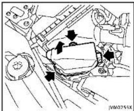
text_image
Technical diagram showing mechanical assembly with labeled components and directional arrows indicating motion or force vectorsENGINECOMPARTMENT

CAUTION
Neveruseafuseofahigherorlower amperageratingthanthatspecifiedonthe fuseboxcover.Thiscoulddamagethe electricalsystemorcauseafire.
Ifanyelectricalequipment does not operate, checkforanopenfuse.
- Besuretheignitionswitchispushed to the OFFForLOCKpositionandthe headlightswitchisturnedtoOFF.
8-22 Maintenance and do-it-yourself
- Opentheenginehood.
- Removethefuse/fusiblelinkholder cover.
- Removethefusewiththefusepuller.
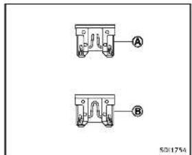
text_image
A B 50/1754- If the fuse is open (A), replace it with a new fuse (B). Spare fuses are restored in the passenger compartment fuse box.
- If an fuse also opens, have the electrical system checked and repaired by an INFINIT retailer.
Fusiblelinks
Ifanyelectrical equipment does not operate and fuses are good condition, check the fusible links. If any of these fusible links are melted, replace only with genuine INFINIT parts.
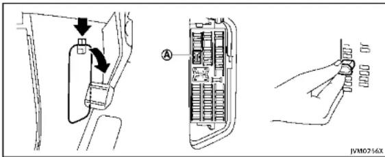
text_image
Technical diagram showing car door panel installation with labeled component A and hand holding connectorPASSENGERCOMPARTMENT

CAUTION
Neveruseafuseofahigherorlower amperageratingthanthatspecifiedonthe fuseboxcover.Thiscoulddamagethe electricalsystemorcauseafire.
If any electricalequipment does not operate, check for an open fuse.
-
Besuretheignitionswitchispushed to the OFFForLOCKpositionandthe headlightswitchisturnedtoOFF.
-
Openthefuseboxlid.
-
Removethefusewiththefusepuller Ⓐ.
-
If the fuse is open, replace it with an new fuse.
-
Ifanewfusealsoopens, havethe electricalsystemcheckedandrepaired by an INFINITretailer. Sparefusesare stored in the fusebox.

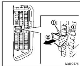
text_image
JVM0257XExtendedstoragefuseswitch(ifso equipped)
Toreducebatterydrain, the extended storagefuseswitchcomesfromthefactory switchedoff. Prior to delivery of your vehicle, the switch is pushedin (switched on) and should always remain on.
Iftheextendedstoragefuseswitchisnot pushedin(switchedon),the"Shipping ModeOn,PushStorageFuse"warningmay appearinthevehicleinformationdisplay. See"18.Extendedstoragefusewarning" (P.2-23).
Ifanyelectricalequipmentdoesnot
Maintenanceanddo-it-yourself8-23
INTELLIGENTKEYBATTERYREPLACEMENT
operate,removetheextendedstoragefuse switchandcheckforanopenfuse.
NOTE:
Iftheextendedstoragefuseswitchmal- functionsorifthefuseisopen,itisnot necessarytoreplacetheswitch.Inthis case,removetheextendedstoragefuse switchandreplaceitwithanewfuseof thesamerating.
Howtoremovetheextendedstoragefuse switch:
- Toremovetheextendedstoragefuse switch, besuretheignitionswitchisin theOFForLOCKposition.
- Besuretheheadlightswitchisinthe OFFposition.
- Removethefuseboxcover.
4.Pinchthelockingtabs ① foundon eachsideofthestoragefuseswitch. - Pullthestoragefuseswitchstraightout fromthefusebox ②.
CAUTION
Becarefulnottoallowchildrenoswallow thebatteryandremovedparts.
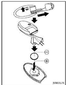
flowchart
graph TD
    A["Sensor Input"] --> B["Device"]
    B --> C{Switch}
    C -->|+| D["Output"]
    C -->|-| E["Ground"]
Toreplacethebattery:
- Releasethelockknobatthebackofthe IntelligentKeyandremovethemechanicalkey.
- Insertaflat-bladescrewdriverwrapped withaclothintotheslitofthecorner andtwistittoseparatetheupperpart
8-24 Maintenance and do-it-yourself
fromthelowerpart.
- Replacethebatterywithanewone.
Recommendedbattery:
CR2025orequivalent
- Donottouchtheinternalcircuitand electricterminalsasitcouldcausea malfunction.
- Holdthebatterybytheedges. Holdingthebatteryacrossthecontactpointswillseriouslydepletethe storagecapacity.
- Makesurethatthe+sidefaceshe bottomofthecase.

text_image
Diagram of a toilet with labeled parts and directional arrows indicating rotation or movement-
Alignthetipsoftheupperandlower parts ①, and thenpushthemtogether ② untilitissecurelyclosed.
-
Operatethebuttonstocheckits operation.
SeeanINFINITretailerifyouneedany assistanceforreplacement.
FCCNotice:
ForUSA:
ThisdevicecomplieswithPart15ofthe
FCC Rules. Operation is subject to the following two conditions: (1) This device may not cause harmful interference, and (2) this device must accept any interfer-
encereceived, including interference that may cause undesired operation.
NOTE:
Changesormodificationsnotexpressly approvedbythepartyresponsiblefor compliancecouldvoidtheuser'sauthority tooperatetheequipment.
ForCanada:
This device complies with RSS-210 of Industry Canada. Operation is subject to the following two conditions: (1) this device may not cause interference, and (2) this device must accept any interference, including interference that may cause undesired operation of the device.
LIGHTS

text_image
7 2 3 4 5 6 7 8 9 10 11 12 13 14 15 16 17 18 JVM0272X1.Headlight(high-beam)
2.Headlight(low-beam)
3.Maplight
4.Frontsidemarkerlight
- Rearpersonallight
6.Sideturnsignallight
7.Frontturnsignallight
8.Foglight
-
Parkinglight
-
Steplight
11.Courtesylight
- High-mounted stoplight
13.Back-uplight
- Reartumsignallight
15.Stoplight/taillight
16Rearsidemarkerlight
17Licenseplatelight
18Trunklight
8-26 Maintenance and do-it-yourself
EXTERIORANDINTERIORLIGHTS
| Item/Wattage(W)Bulb/No. | ||
| Headlight*High/Lowbeamsl.FD-Frontturnsignallight*LED-Frontfoglight*LED-Parkinglight*LED-Sidemarkerlight*LED-Rearcombinationlight*back-up*LED-turnsignal21WY21Wstop/tail/sidemarker*LED-LicenseplatelightMaplight*RearpersonallightVanitynlrrorlightStoplightSTranklightCourtesylight*High-mountedstoplight* | 5LED823.4LED-LED- | W5W-- |
*:SeeanINFINITretailerfor replacement.
NOTE: Always check with the Parts Department at an INFINITE retailer for the
ment at an INFINITE retailer for the latest informationaboutparts.

Replacementprocedures
AllotherlightsareeithertypeA,B,C,D,E
or F. When replacing a bulb, first remove the lens and/or cover.

flowchart
graph TD
    A["REMOVE"] --> B["INSTALL"]
    B --> C["A"]
    C --> D["B"]
    D --> E["C"]
    E --> F["D"]
    F --> G["E"]
    G --> H["F"]
    style A fill:#f9f,stroke:#333
    style B fill:#ccf,stroke:#333
    style C fill:#cfc,stroke:#333
    style D fill:#fcc,stroke:#333
    style E fill:#cff,stroke:#333
    style F fill:#ffc,stroke:#333
    style G fill:#cfc,stroke:#333
    style H fill:#fcc,stroke:#333
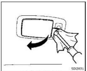
natural_image
Hand holding a device with an arrow indicating motion (no text or symbols)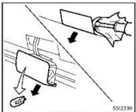
text_image
Technical diagram showing mechanical assembly with labeled components and directional arrows
text_image
Rearpersonlaught S01839
flowchart
graph TD
    A["Steplight"] --> B["Steplight ①"]
    A --> C["Steplight ②"]
    B --> D["Arrow ①"]
    C --> E["Arrow ②"]
    D --> F["Arrow ②"]
    E --> F
    style A fill:#f9f,stroke:#333
    style B fill:#ccf,stroke:#333
    style C fill:#ccf,stroke:#333
    style D fill:#fff,stroke:#333
    style E fill:#fff,stroke:#333
Vanity mirror light
8-28 Maintenance and do-it-yourself
WHEELSANDTIRES
If you have a flattire, see "Flattire" (P.6-3).
TIREPRESSURE
TirePressureMonitoringSystem (TPMS)
This vehicleisequipped with the Tire Pressure Monitoring System (TPMS). It monitor tire pressure of all tire except these spare. Whentelow tire pressure warning lights lit and the "Tire Pressure Low-Add Air" warning appears in the vehicle information display, one more or more your tiresis significantly under inflated. The TPMS will activate only when the vehicle is driven at speeds above 16 MPH (25 km/h). Also, this system may not detect a sudden drop in tire pressure (for example afall tire while driving).
Formoredetails,see"Lowtirepressure warninglight"(P.2-14),"TirePressureMonitoringSystem(TPMS)("P.5-4)and"Tire PressureMonitoringSystem(TPMS)("P.6-3).
Tireinflationpressure
Checkthepressureofthetires (includingthespare)oftenandal-
wayspriortolongdistancetrips. The recommended tirepressures specificationsareshownontheTireand LoadingInformationlabelunderthe "ColdTirePressure"heading. The TireandLoadingInformationlabelis affixedtothedriversidecenterpillar. Tirepressuresshouldbechecked regularlybecause:
- Mosttiresnaturallyloseairover time.
- Tirescanloseairsuddenlywhen drivenoverpotholesorother objectsonifthevehiclestrikesa curbwhileparking.
Thetirepressureshouldbechecked whenthetiresarecold. Thetires are consideredCOLDafterthevehicle has beenparkedfor3ormorehours, ordrivenlessthan1mile(1.6km)at moderatespeeds.
TPMS with Tire Inflation Indicator provides visual and audible signals outside the vehicle for inflating the tires to the recommended COLD tire pressure.(See"TPMSwithTireInflationIndicator"(P.5-7)aboutthe TPMSwithTireInflationIndicator.)
Incorrect tire pressure, including underinflation, may adversely affect tire life and vehicle handling.

WARNING
- Improperlyinflatedtirescanfail suddenlyandcauseanaccident.
- TheGrossVehicleWeightrating (GVWR)islocatedonthef.M.V.S. S./C.M.V.S.S.label.Thevehicle weightcapacityisindicated on theTireandLoadingInformation label.Donotloadyourvehicle beyondthiscapacity.Overloading yourvehiclemayresultinreduced tirelife,unsafeoperatingconditionsduetoprematuretirefailure, orunfavorablehandlingcharacteristicsandcouldalsoleadtoa seriousaccident Loadingbeyond thespecifiedcapacitymayalso
Maintenanceanddo-it-yourself
resultinfailureofothervehicle components.
●Beforetakingalongtrip,or wheneveryouheavilyloadyour vehicle,useatirepressuregauge toensurethatthetirepressures areatthespecifiedlevel.
- For additional information regarding tires, refer to "Important Tire Safety Information" (US) or "Tire Safety Information" (Canada) in the Warranty Information Booklet.

text_image
Technical diagram with numbered annotations and labeled components, likely from a technical or engineering document.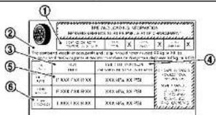
text_image
① ② ③ ④ ⑤ ⑥ 1.000 100.000 250 2.000 100.000 250 3.000 100.000 250 4.000 100.000 250 5.000 100.000 250 6.000 100.000 250 7.000 100.000 250 8.000 100.000 250 9.000 100.000 250 10.000 100.000 250 11.000 100.000 250 12.000 100.000 250 13.000 100.000 250 14.000 100.000 250 15.000 100.000 250 16.000 100.000 250 17.000 100.000 250 18.000 100.000 250 19.000 100.000 250 20.000 100.000 250 21.000 100.000 250 22.000 100.000 250 23.000 100.000 250 24.000 100.000 250 25.000 100.000 25 26.005012567
TireandLoadingInformationlabel
① Seatingcapacity:Themaximum number of occupants that can be seated in the vehicle.
② Vehicle load limit; See "Vehicle loading information" (P.9-16).
③ Original size: The size of the tires originally installed on the vehicle atthefactory.
④ Cold tire pressure: Inflatethe tirestothispressurewhenthe tiresarecold.Tiresareconsid-
ered COLD after the vehicle has been parked for 3 or more hours, or driven less than 1 mile (1.6 km) at moderate speeds. The recommended cold tire inflation is set by the manufacturer to provide the best balance of tire wear, vehicle handling, driveability, tire noise, etc., up to the vehicle's GWRP.
⑤ Tire size — see "Tire labeling" (P.8-32).
⑥ Spare tire size or compact spare tire size (if so equipped)
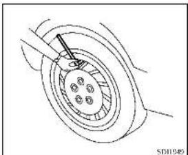
natural_image
Technical line drawing of a mechanical component with no visible text or symbolsChecking the tire pressure
-
Remove the valve stem cap from the tire.
-
Press the pressure gauge squarely onto the valve stem. Do not press too hard or force the valve stem sideways, or air will escape. If the hissing sound of air escaping from the tire is heard while checking the pressure deposition on the gauge to eliminate this leakage.
-
Remove the gauge.
- Read the tire pressure on the gauge stem and compare it to the specification shown on the Tire and Loading Information label.
- Add air to the tire as needed. If too much air is added, press the core of the valve stem briefly with the tip of the gauge stem to release pressure. Recheck the pressure and add or release air as needed.
- Install the valve stem cap.
- Check the pressure of all other tires, including the spare.
| SIZE | COLDTIRE INFLATION PRESSURE | |
| FRONT ORIGINAL TIRE | P225/55RF1795V | 240kPa,35PSI |
| P245/40RF1994V | 240kPa,35PSI | |
| 245/40RF1994W | 240kPa,35PSI | |
| REARORI-GINALTIRE | P225/55RF1795V | 240kPa,35PSI |
| P245/40RF1994V | 240kPa,35PSI | |
| 245/40RF1994W | 240kPa,35PSI | |
| SPARETIRE (Ifso equipped) | T145/70R18107M | 420kPa,60PSI |
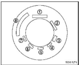
text_image
① ② ③ ④ ⑤ ⑥ ⑦ ⑧ SDH575Example
TIRELABELING
Federallawrequirestiremanufacturerstoplacestandardizedinformationonthesidewallofaltilties.This informationidentifiesanddescribes the fundamentalcharacteristicsof thetireandalsoprovidesthetire identificationnumber(TIN)for safety standardcertification.TheTINcanbe used to identify the tire in case of a recall. Information Provided by

text_image
P215/60R16 94H P 215 60 R 16 94 H 1 2 3 4 5 6 7 501606Example
① Tiresize(example:P215/60R1694H)
- P:The"P"indicatesthetireis designedforpassengervehicles. (Notalltireshavethisinformation.)
- Three-digitnumber(215):This numbergivesthewidthinmillimetersofthetirefromsidewall edgetosidewalledge.
- Two-digitnumber(60):Thisnumber,knownastheaspectratio,
givesthetire's ratio of height to width.
- R: The "R" stands for radial. F: The "F" after "R" indicates Self-Supporting type per un-flattire.
- Two-digitnumber(16):Thisnumberisthewheelorrimdiameterin inches.
- Two-orthree-digitnumber(94): This numberisthetire'sload index.Itisameasurementof how much weighteachtire can support.You may not find this information all tires because it is not required by law.
- H:Tirespeedrating.Youshould notdrivethevehiclefasterthan thetirespeedrating.
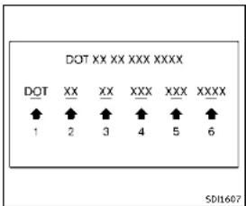
- DOT: Abbreviation for the "Department of Transportation". Thesymbol can be placed above, below or to the left or right of the Tire Identification Number.
- Two-digit code: Manufacturer's identification mark
-
Two-digit code: Tire size
-
Three-digitcode:Tiretypecode (Optional)
- Three-digitcode:DateofManufacture
- Fournumbersrepresenttheweek andyearthetirewasbuilt. For example, thenumbers3103 meansthe31stweekof2003. If thesenumbersaremissing,then lookontheothersidewallofthe tire.
③ Tireplycompositionandmaterial Thenumberoflayersorpliesof rubber-coatedfabricinthetire.
Tiremanufacturersalsomustindicatethematerialsinthetire,which includesteel,nylon,polyester,and others.
④ Maximumpermissibleinflation pressure
Thisnumberisthegreatestamount of airpressurethatshouldbeputin thetire.Donotexceedthemaximum
permissibleinflationpressure.
⑤ Maximumloadrating
Thisnumberindicatesthemaximum loadinkilogramsandpoundsthat canbecarriedbythetire.When replacingthetiresonthevehicle, alwaysuseatirethathasthesame loadratingasthefactoryinstalled tire.
⑥ Term of "tubeless" or "tube type" Indicates whether the itrierequires an innertube("tubetype") or not ("tubeless").
⑦ Theword"radial"
Theword"radial"isshown,ifthetire hasradialstructure.
⑧ Manufacturerorbrandname Manufacturerorbrandnameis shown.
Othertire-related terminology: Inadditiontothemanytermsthat aredefinedthroughoutthissection,
8-34 Maintenance and do-it-yourself
IntendedOutboardSidewallis(1)the sidewallthatcontainsawhitewalk, bearswhiteletteringorbearsmanufacturer,brandand/ormodelname moldingthatishigherordeeperthan thesamemoldingonthe othersidewallofthetire,or(2)theoutward facingsidewallofanasymmetrical tirethathasaparticularsidethat mustalwaysfaceoutward when mountedonavehicle.
TYPESOFTIRES
WARNING
- Whenchangingorreplacingtires, be sureallfourtiresareofthesametype (Example:Summer,All SeasonorSnow) and construction.AnINFINITretailer may be able to help you with information abouttiretype,size,speedratingand availability.
- Replacement tires may have a lower speed rating than the factory equipped tires, and may not match the potential maximum vehicle speed. Never exceed
themaximum speedrating of the tire.
- Replacing tires with those not originally specified by INFINIT could affect the proper operation of the TPMS.
- Foradditionalinformationregarding tires,referto"ImportantTireSafety Information"(US)or"TireSafetyInformation" (Canada) in the Warranty InformationBooklet.
Allseasontires
INFINITI specifies all season tires on some modelstoprovidegoodperformanceall year, including snowy and icy road conditions. AllSeasontiresareidentifiedbyALL.SEASONand/orM&S(MudandSnow)on thetiresidewall.Snowtireshavebetter snowtractionthanAllSeasontiresand maybe moreappropriate insome areas.
Summerlires
INFINITspecifiessummertiresonsome modelsto providesuperiorperformance on dryroads.Summertireperformanceis substantiallyreducedinsnowandice. Summer tires do not have the tire traction ratingM&S onthe tiresidewall.
If you plan to operate your vehicle in snowy
oricyconditions, INFINITI recommends the use of SNOW tires or ALL SEASON tires on all four wheels.
Snowtires
Ifsnowtiresareneeded,itsnecessaryto selecttiresequivalentinsizeandload ratingtotheoriginalequipmenttires.If youdonot,itcanadverselyaffectthe safetyandhandlingofyourvehicle.
Generally, snowtireswillhavelowerspeed ratingsthanfactoryequippedtiresand maynotmatchthepotentialmaximum vehiclespeed. Neverexceedthemaximum speedratingofthetire.
If you install snowtires, they must be the same size, brand, construction and tread pattern on all four wheels.
For additional traction on icy roads, studded tires maybe used. However, some U.S. states and Canadian provinces prohibit their use. Check local, state and provincial laws before installing studded tires. Skid and traction capabilities of studded snowtires, on wetordry surfaces, may be poorer than that of non-studded snowtires.
Run-flattires
Yourvehicleisequippedwithrun-flattires. Youcancontinuedrivingtoasafelocation eveniftheyarepunctured. Alwaysuserun-flattiresofthespecifiedsizeonallfour wheels. Mixingtiresizesorconstruction mayreducevehiclehandlingstability. If necessary, contactanINFINITretailerfor assistance.
Frequentlycheckthetirepressure and adjust pressure of each tire properly. The tire pressure can be also checked in the vehicle information display.
Itcanbedifficulttotellfarun-flattireis under-inflatedorflat.Checkthetire pressuresasdescribedearlierinthis section.Ifthetirebecomesunder-inflated whiledriving,thelowtirepressurewarning lightwillilluminate.Ifthetirebecomesflat whiledriving,thelowtirepressurewarning lightandthe"FlatTire-Visitdealer" warningwillappear.
Lowtirepressure:
If the vehicle is being driven with low tire pressure, the low tire pressure warning light will illuminate.
Flattire:
Ifthevehicleisbeingdrivenwithoneor moreflattires,thelowtirepressure warninglightwillilluminatecontinuously andachimewillsoundfor10seconds.A "FlatTire-Visitdealer"warningalso appearsinthevehicleinformationdisplay.
Thechimewillonlysoundatthefirst indicationofaflattireandthewarning lightwillilluminatecontinuously. Whenthe flattirewarningisactivated, havethe systemresetandthetirecheckedand replacedifnecessarybyanINFINITretailer. Evenifthetireisinflatedtothe specifiedCOLDtirepressure, thewarning lightwillcontinuetoilluminateuntilthe systemisresetbyanINFINITretailer.
Ifthelowtirepressurewarninglight illuminatescontinuouslyandthe"FlatTire-Visitdealer"warningappearsinthe vehicleinformationdisplay:
- Donotexceed50MPH(80km/h). - Increaseyourfollowingdistanceto allowforincreasedstoppingdistances.
●Avoidsuddenmaneuvers,hardcorneringandhardbraking.

Maintenanceanddo-it-yourself8-35

WARNING
- Although you can continued driving with punctured run-flattire, remember that vehicle handling stability is reduced, which could lead to an accident and personal injury. Also, driving along distance at high speeds may damage the tire.
- Donotdriveatspeedsabove50MPH (80km/h)anddonotdrivemorethan approximately93miles(150km)witha puncturedrun-flattire.Theactualdistancethevehiclecanbedrivenonaflat tiredependsonoutsidetemperature, vehicleload,roadconditionsanother factors.
- Drivesafelyatreducedspeeds.Avoid hardcorneringorbraking,whichmay causeyoutolosecontrolofthevehicle.
- If you detect any unusual sounds or vibrations while driving with apunctured run-flattire, pullofftheroadtoasafe location and stop the vehicle as soon as possible. The tire may be seriously damaged and need to be replaced.

CAUTION
■Neverinstalltirechainsonapunctured run-flattire,asthiscoulddamageyour vehicle.
■AvoIddrivingoveranyprojectionor pothole,astheclearancebetweenthe vehicleandthegroundissmallerthan normal.
- Donotenteranautomatedcarwashwith apuncturedrun-flattire.
●Havethepuncturedtireinspectedbyan INFINITretailerorotherauthorized repairshop. Replacethetireassoon aspossibleifthetireisseriously damaged.
TIRECHAINS
Useoftirechainsmaybeprohibited according to location. Check the local laws beforeinstallingtirechains.Wheninstallingtirechains,makesuretheyarethe propersizeforthetiresonyour vehicleand are installed according to the chain manufacturer's suggestions. Use only SAE Class S chains. Class "S" chains are used on vehicles with restricted tire to vehicle
clearance.VehiclesthatcanuseClass"5" chainsaredesignedtomeettheSAE standardminimumclearancesbetween the tire and the closest vehicle suspension orbodycomponentrequiredtoaccommodatetheuseofawintertractiondevice(tire chains or cables). The minimum clearances are determined using the factory equipped tiresize.Othertypesmaydamageyour vehicle. Use chain tensioners when recommendedbythetirechainmanufacturer to ensureahtightfit.Looseendlinksothe tirechainmustbesecuredorremovedto preventthepossibilityofwhippingaction damagetothefendersorunderbody.of possible, avoidfullyloadingyourvehicle whenusingtirechains.Inaddition,driveat areducedspeed.Otherwise,yourvehicle maybedamagedand/orvehiclehandling andperformancemaybeadverselyaffected.
Tirechainsmustbeinstalledonlyonthe
fearwheelsandnotonthrentontwheels. NeverinstalltirechainsonaTEMPORARY USE ONLY spare tire (if so equipped). Never installtirechainsonapuncturedrun-flat tire,asthiscoulddamageyourvehicle. Donotusetirechainsondryroads. Driving withtirechainsinsuchconditionscan
causedamagetothevariousmechanisms ofthevehicleduetosomeoverstress.

text_image
SD1662CHANGINGWHEELSANDTIRES
Tirerotation
INFINITI recommends rotating the tires every 5,000 miles (8,000 km). (See "Flattire" (P.6-3) fortirereplacing procedures.)
Assoonaspossible,tightenthe wheelnutstothespecifiedtorque withatorquewrench.
Wheel nut tightening torque: 80 ft-lb (108 N·m)
Thewheelnutsmustbekepttigh- tenedtothespecificationatall times. It is recommended that wheel nutsbetightenedtothespecifica- tionateachtirerotationinterval.

WARNING
•Afterrotatingthetires,checkand adjustthetirepressure.
- Retightenthewheelnutswhen thevehiclehasbeendrivenfor 600miles(1,000km)(alsoin casesofaflattire,etc.).
- DonotincludetheT-typespare tireoranyothersmallsizespare tireinthetirerotation.
- For additional information regarding tires, referto "Important Tire Safety Information" (US) or "Tire Safety Information" (Canada) in the Warranty Information Booklet.
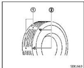
text_image
① ② SDI:663- Wearindicator
- Wearindicatorlocationmark
Tirewearanddamage

WARNING
- Tiressshouldbeperiodicallyin- spectedforwear, cracking, bul- gingorobjectscaughtinthe tread. Ifexcessivewear, cracks, bulgingordeepcutsarefound, thetire(s)shouldbereplaced.
●Theoriginaltireshavebuilt-in treadwearindicators.Whenwear indicatorsarevisible,thetire(s) shouldbereplaced.
●Tiresdegradewithageanduse. Havetires,includingthespare, over6yearsoldcheckedbya qualified technician, because sometiredamagemaynotbe obvious. Replacethetiresas necessarytopreventtirefailure andpossiblepersonalinjury.
- Improperserviceofthesparetire mayresultinseriouspersonal injury. If it is necessary to repair thesparetire,contactanINFINITI retailer.
- For additional information regarding tires, refer to "Important Tire Safety Information"(US)or"Tire Safety Information"(Canada)in the Warranty Information Booklet.

Replacingwheelsandtires
When replacing atire, usethesamesize, treaddesign, speedrating and load carry-ing capacity as originally equipped. (See "Specifications" (P.9-8) for recommended types and sizes soft tires and wheels.)

WARNING
- Theuseoftiresotherthanthose recommendedorthemixeduseoftires of different brands, construction (bias, bias-belted, radialorrun-flat), ortread patterns can adversely affect the ride, braking, handling, ground clearance, body-to-tire clearance, tire chain clearance, speedometercalibration, headlightaimand bumperheight. Someof these effects may lead to accidents and could result in serious personal injury.
- For Two-Wheel Drive (2WD) models, If your vehicle was originally equipped with 4 tires that were the same size and you are only replacing 2 of the 4 tires, install the new tires on the rear axle. Placing new tires on the frontaxle may cause loss of vehicle control in some driving conditions and cause an
8-38 Maintenance and do-it-yourself
accidentandpersonalinjury.
- If the wheels are changed for any reason, always replace with wheels which have the same off-set dimension. Wheel so far different off-set could cause premature tire wear, degrade vehicle handling characteristics and/or interference with the braked discs/drums. Such interference can lead to decreased braking efficiency and/or early brake pad/show wear. See "Wheelsandtries" (P.9-9) of this manual for wheel off-set dimensions.
- Whenasparetireismountedorawheel isreplaced, theTPMSwillnotfunction andthelowtirepressurewarninglight willflashforapproximately1minute. Thelightwillremainonafter1minute. ContactyourINFINITretailerassoonas possiblefortirereplacementand/or systemresetting.
●Replacing tires with those not originally specified by INFINIT could affect the proper operation of the TPMS.
- Donotinstalladamagedordeformed wheelortireevenifithasbeenrepaired. Suchwheelsortirescouldhavestructuraldamageandcouldfailwithout
warning.
•Theuseofretreadtireisnotrecommended.
- For additional information regarding tires, referto "Important Tire Safety Information" (US) or "Tire Safety Information" (Canada) in the Warranty Information Booklet.
IntelligentAll-WheelDrive(AWD) models
CAUTION
●Alwaysusetiresofthesametype,size, brand,construction(bias,bias-beltedor radial),andtreadpatternonallfour wheels.Failureretodosomayresultina circumferencedifferencebetweentires onthefrontandrearaxeswhichwill causeexcessivetirewearandmay damageethetransmission,transfercase anddifferentialgears.
- ONLY use spare tires specified for the Intelligent AWD model.
If excessive tire wear is found, it is
recommendedthatallfourtiresbere- placedwithtiresofthesamesize,brand, constructionandtreadpattern.Thetire pressureandwheelalignmentsshouldalso becheckedandcorrectedasnecessary. ContactanINFINITlretailer.
Wheelbalance
Unbalancedwheelsmayaffectvehicle handlingandtirelife.Evenwithregular use, wheelscangetoutofbalance.Therefore,theyshouldbebalancedasrequired. Wheelbalanceserviceshouldbeperformedwiththewheelsoffthevehicle. Spinbalancingthewheelsonthevehicle couldleadtomechanicaldamage.
For additional information regarding tires, refer to "Important Tire Safety Information" (US) or "Tire Safety Information" (Canada) in the INFINITI Warranty Information Booklet.
Careofwheels
See "Cleaningexterior" (P.7-2) fordetails about care of the wheels.
Sparetire(TEMPORARYUSEONLY (T-type)sparetire)(ifsoequipped)
Whenasparetireismounted(TEMPORARY USEONLY),theTirePressureMonitoring System(TPMS)willnotfunction.
Observethefollowingprecautionsifthe TEMPORARYUSEONLYsparetiremustbe used,otherwiseyourvehiclecouldbe damagedorinvolvedinanaccident.

WARNING
•TheTEMPORARYUSEONLYsparetire shouldbeusedforemergencyuse.It shouldbereplacedwiththestandard tireatthefirstopportunitytoavoid possibletireordifferentialdamage.
- DrivecarefullywhiletheTEMPORARY USEONLYsparetireisinstalled.Avoid sharpturnsandabruptbrakingwhile driving.
•Periodicallychecksparetireinflation pressure. Alwayskeepthepressureof theTEMPORARYUSE ONLYspare treat 60psi(420kPa,4.2bar).Alwayskeep thepressureofthefullsizesparetire(if so equipped) at the recommended pressureforstandardtires,asindicatedon
8-40 Maintenance and do-it-yourself
theTireandLoadingInformationlabel. For Tire and Loading Information label, see "Tire and loading information label" (P.9-13).
■WiththeTEMPORARYUSEONLYspare tireinstalleddonotdrive yourvehicle at speedsfasterthan 50 MPH(80 km/h).
- When driving on roads covered with snow orice, the TEMPORARY USE ONLY spare tires should be used on the front wheels and original tire used on the rear wheels (drivewheels). Usetirechains only on the two rear original tires.
- Tire tread of the TEMPORARY USE ONLY spare tire will wear a fasterratethan the standard tire. Replace the spare tire as soon as the tread wear indicators appear.
- Donotusethesparetireonother vehicles.
- Do not use more than one spare tire at thesametime.

CAUTION
- Do not use tire chains on a TEMPORARY USE ONLY spare tire. Tire chains will not
fitproperlyandmaycausedamageto thevehicle.
●Because the TEMPORARY USE ONLY spare tire is smaller than the original tire, ground clearance is reduced. To avoid damage to the vehicle, donot drive over obstacles. Also on to drive the vehicle through an automatic car wash since it may get caught.
9Technicalandconsumerinformation
Capacitiesandrecommendedfuel/lubricants.....9-2
Fuelinformation....9-4
Engineoilandoilfilterrecommendation....9-6
Airconditioningsystemrefrigerantand
lubricantrecommendations....9-7
Specifications....9-8
Engine....9-8
Wheelsandtires....9-9
Dimensions....9-10
Whentravelingorregisteringyourvehiclein
othercountry....9-11
Vehicleidentification....9-11
VehicleIdentificationNumber(VIN)plate.....9-11
Vehicleidentificationnumber
(chassisnumber)....9-11
Engineserialnumber....9-12
F.M.V.S.S./C.M.V.S.S.certificationlabel.....9-12
Emissioncontrolinformationlabel....9-12
Tireandloadinginformationlabel....9-13
Airconditionerspecificationlabel....9-13
Installingfrontlicenseplate....9-14
Removingairdeflectors....9-15
Vehicleloadinginformation....9-16
Terms....9-16
Vehicleloadcapacity....9-17
Loadingtips....9-18
Measurementofweights....9-18
Towingatrailer....9-19
Flattowing....9-19
Uniformtirequalitygrading....9-19
Treadwear....9-19
TractionAA,A,BandC....9-20
TemperatureA BandC 9-20
Emissioncontrolsystemwarranty....9-20
Reportingsafetydefects....9-21
ReadinessforInspection/Maintenance(I/M)test
(USonly)....9-22
EventDataRecorders(EDR)....9-23
Owner'sManual/ServiceManual
orderinformation....9-23
CAPACITIESANDRECOMMENDEDFUEL/
LUBRICANTS
The following are approximate capacities. The actual refill capacities may be a little different. When refilling, follow the procedure instructed in the "8. Maintenance and do-it-yourself" section to determine the proper refill capacity.
| Capacity(Accoutrate) | Recommended specifications | |||
| USmeasurement measure for | ||||
| Fuel/20gatts 5-8gwt/4Ser*Flue/information*(P,9-6) | ||||
| Ergicoil*2 | ||||
| Desiredefill. | ||||
| Without/Other change | 3-1/8gwt-3/8gwt-4.9 | • Genuine/NISSA/Kergine/Ionequivalent*1• Ergicoil with APCertificationMars*10• Viscosity/SCLNA-30 | ||
| Without/Different change | 4-7/8gwt | 4.0g | 4.6 | |
| Cooling system | ||||
| Withensor | 11-1/2g | 9-5/8g | 10.9 | Pre-filtration/genuine/NISSA/Lung, Dekn/Freeze/CodomainBlue/onequivalent |
| Reservoir | 1st | 1/2gwt | 0.9 | |
| Automatic transmission fluid | — | — | — | Genuine KISSAR Music S ATP*3 |
| Differential/perseal | — | — | — | Front: Genuine NISSIA Differential Oil Hybrid Super Gc 5 80W-90 or API GL-3, Viscosity SML RTa-90*4Ran: APGL-Synthetic/perseol,ViscositySML73W-90*5 |
| Transfer fluid | — | — | — | Genuine KISSAR Music L ATP*6 |
| Power scaling fluid (VSP) | Refill to the proper mill level according to the instructions in the PS. Maintenance and use yourself section. | Genuine/NISSA/RPS/Onequivalent*7Genuine/NISSA/Superclass/Duty Brake Fluid/Baregulation/HoT*1 | ||
| Breakfast | — | — | — | |
| Multi-purpose process | — | — | — | MLG/Mn 20/10/Iminephase[ ] |
| Air conditioning system relevant | — | — | — | HFC13ta [R-13sa]*9 |
| Aircond/mile/geosystem-like tests | — | — | — | NISSAA/CSystem/DISP-10 for exact/evalent |
| Window/waste fluid | — | — | — | Genuine/NISSA/Indirect/Airchase Co-reactrateClame A/Intracerequevalent |
*1: INFINITE recommends Genuine NISSANEster Engine Oil available by your INFINITE retailer.
*2: For additional information, see "Engine oil" (P.B-10) for changing engine oil.
*3: Using automatic transmission fluid other than Genuine NISSAN Matric S ATF will cause deterioration in driveability and automatic transmission durability, and may damage the automatic
transmission, which is not covered by the INFINITE new vehicle limited warranty.
*4: For hot climates, viscosity SAE 90 is suitable for ambient temperatures above 32°F (0°C).
*5: SeananIFINITretailerforservicearsynthetrol.
9-2Technicalandconsumerinformation
*6: Using transfer fluid other than Genuine MISSAN Matic | ATF will cause deterioration in driveability and transfer durability, and may damage the transfer, which is not covered by the INFINITI new vehicle-limited warranty.
*: DEYRONI Wihue#Tfey
*8: avail. shiein mainland 15.3 through xolk EIKITretailer
*9: For additional information, see "Vehicle Identification" (P.9-11) for air conditioner specification label.
*10: For additional information, see "Engine oil and oil filter recommendation" (P.9-6).

Technicalandconsumerinformation9·3
FUELINFORMATION
Useunleadedpremiumgasolinewithan octaneratingofatleast91AKI(Anti-Knock Index)number(Researchoctanenumber 96).
Ifpremiumgasolineisnotavailable, unleadedregulargasolinewithanoctane ratingof87AKlnumber(Researchoctane number91)maybetemporarilyused,but onlyunderthefollowingprecautions:
●Havethefueltankfilledonlypartially withunleadedregulargasoline,andfill upwithunleadedpremiumgasolineas soonaspossible.
- Avoidfullthrottledrivingandabrupt acceleration.
Useunleadedpremiumgasolineformax- imumvehicleperformance.

CAUTION
- Usingafuelotherthanthatspecified couldadverselyaffecttheemission controlsystem,andmayalsoaffect warrantycoverage.
- Undernocircumstances should leadaded gasoline beused, because this will damage the three-way catalyst.
9-4 Technical and consumer information
- DonotuseE-15orE-85fuelinyour vehicle. Your vehicle is not designed to runon E-15orE-85fuel. Using E-15orE-85fuel in vehiclenots specifically designed for E-15orE-85 fuel can adversely affect the emission control devices and system software. Damage caused by such fuels not covered by the INFINIT new vehicle limited warranty.
•U.S. government regulations require ethanoldispensingpumpstobeidentified byasmall, square, orange and black label with the common abbreviation or the appropriate percentage for that region.
Gasolinespecifications
INFINITirecommendsusinggasolinethat meetstheWorld-WideFuelCharter(WWFC) specificationswhereitisavailable.Many oftheautomobilemanufacturersdevelopedthisspecificationtoimproveemissionsystemandvehicle performance.Ask your service station manager if the gasoline meets the World-Wide Fuel Charter (WWFC)s pecifications.
Reformulated gasoline
Somefuelsuppliers arenow producing reformulatedgasolines.Thesegasolines arespeciallydesignedtoreducevehicle emissions.INFINITIsupportseffortstowardscleanerairandsuggeststhatyou usereformulated gasoline whenavailable.
Gasolinecontainingoxygenates
Some fuelsuppliersell gasolinecontainingoxygenatessuchasethanol,MTBEand methanol with or without advertising their presence.INFINITIdoesnotrecommendthe useoffuelsofwhichthepoxygenatecontent and the fuel compatibility for your INFINITI cannot bereadilydetermined. Ifindoubt, askyour service stationmanager.
If you use oxygenate-blend gasoline, pleasetakethefollowing precautions as the usage of such fuels may cause vehicle performance problems and/or fuel system damage.
- Thefuel should be unleaded and have an octanerating nolower than that recommended for unleaded gasoline.
- Ifanoxygenate-blend, excepting a methanol blend, is used, it should contain no more than 10% oxygenate. (MTBEmay, however, beadedupto
15%.)
•E-15fuelcontainsmorethan10% oxygenate.E-15fuelwilladversely affecttheemissioncontroldevices andsystemsofthevehicleandshould notbeused.Damagecausedbysuch fuelisnotcoveredbytheINFINITINew VehicleLimitedWarranty.
ifamethanolblendisused, it should containnonmore than 5% methanol (methylalcohol, woodalcohol). It should also contains suitable amount of appropriate cosolvents and corrosion inhibitors. If not properly formulated with appropriate cosolvents and corrosion inhibitors, such methanol blends may cause fuel system damage and/or vehicle performance problems. At this time, sufficient details not available to ensure that all methanol blends are suitable for use in INFINITE vehicles.
Ifanyundesirabledriveabilityproblems suchasenginestallingorhardhotstarting areexperiencedafterusingoxygenateblendfuels,immediatelychangetoa non-oxygenatefuelorafuelwithalow blendofMTBE.
Takecarenottospillgasolineduring refueling.Gasolinecontainingoxygenates cancausepaintdamage.
E-15fuel
E-15fuelisamixtureofapproximately 15%fuelethanoland85%unleaded gasoline. E-15canonlybeusedinvehicles designedorunon E-15fuel. Donotuse E-15inyourvehicle. U.S. government regulations require fuelethanoldispensing pumpstobeidentifiedwithsmall, square, orange and black label with the common abbreviation or the appropriate percentage for that region.
E-85fuel
E-85fuelisamixtureofapproximately 85%fuelethanoland15%unleaded gasoline. E-85canonlybeusedina FlexibleFuelVehicle(FFV). DonotuseE-85fuelinyourvehicle.U.S. government regulationsrequirefuelethanoldispensing pumpstobeidentifiedbyasmall, square, orangeandblacklabelwiththecommon abbreviationortheappropriatepercentage forthar region.

Aftermarketfueladditives
INFINITdoesnotrecommendtheuseof anyaftermarketfueladditives(Example: fuelinjectorcleaner, octanebooster, intake valvedepositremovers, etc.),whichare soldcommercially.Manyoftheseadditives intendedforgum, varnishordeposit removalmaycontainactivesolventor similaringredientsthatcanbeharmfulto thefuelsystemandengine.
Octaneratingtips
Using unlegadedgasoline with an octane rating lower than recommended above can cause persistent, heavysparkknock. (Sparkknock is a metallic rapping noise.) If severe, this can lead to an injured damage. If you detect epistersent the heavyspark knock even when using gas gasoline of the stated octanating, or if you hear steady sparkknock while holding a steady speed on levelroads, have an infinitretailer correct the condition. Failure to correct the condition is misuse the vehicle, for which infinitile is not responsible.
Incorrect ignition timing will result in knocking, after run over heating. This turn may cause excessive fuel consumption, or damage to the engine. If any of the
Technicalandconsumerinformation9·5
above symptoms are encountered, have your vehicle checked at an INFINIT retailer or other competent service facility. However, now and then you may notice lightsparknockforashort timwhile accelerating or driving up hills. This is no cause for concern, because you get the greatest fuel benefit when there is light sparkknockforashort time under heavy engine load.
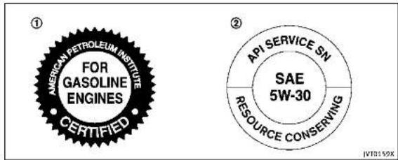
1.APlcertificationmark
2.APIservicesymbol
ENGINEOILANDOILFILTERRE-COMMENDATION
Selectingthecorrectoil
Itisessentialtochoosethecorrectgrade, quality,andviscosityengineoiltoensure satisfactoryenginelifeandperformance, see"Capacitiesandrecommendedfuel/lubricants" (P.9-2). INFINITI recommends the use of an energy conserving oil in order to improve fuel economy.
Select only engine oils that meet the
AmericanPetroleumInstitute(API)certificationInternationallubricantStandardizationandApprovalCommittee(ILSAC)certificationandSAEviscositystandard. TheseoilshavetheAPlcertificationmark on the front of the container. Oils which do not have the specified quality label should notbeusedastheycouldcauseengine damage.
Oiladditives
INFINITI does not recommend the use of oil additives. Theuseofanoladditivesnot necessary when the proper oil type is used andmaintenanceintervalsarefollowed.
Oilwhichmaycontainforeignmatteror hasbeenpreviouslyusedshouldnotbe used.
Oilviscosity
Theengineoilviscosityorthickness changeswithtemperature. Becauseofthis, itisimportantthattheengineoilviscosity beselectedbasedonthetemperaturesat whichthevehiclewillbeoperatedbefore thenextoilchange.Choosinganoil viscosityotherthanthatrecommended couldcauseseriousenginedamage.
Selectingthecorrectoilfilter
Yournewvehicleisequippedwithahigh-qualitygenuineNISSANoilfilter.When replacing,usethegenuineoilfilterorits equivalentforthereasondescribedin changeintervals.
Changeintervals
Theoilandoilfilterchangeintervalsfor youreginearebasedontheuseofthe specifiedqualityoilsandfilters. Oiland filterotherthanthespecifiedquality,oroil andfilterchangeintervalslongerthan recommendedcouldreduceenginelife. Damagetoenginescausedbyimproper maintenanceoruseofincorrectoiland
filterqualityand/orviscosityisnotcovered bythenewINFINITvehiclelimitedwarranties.
Yourenginewasfilledwithahighquality engineoilwhenitwasbuilt.Youdonot havetochangetheoilbeforethefirst recommendedchangeinterval.Oiland filterchangeintervalsdependuponhow youseyourvehicle.Operationunderthe followingconditionsmayrequiremore frequentoilandfilterchanges.
■repeatedshortdistancedrivingatcold outsidetemperatures,
●drivingindustyconditions,
•extensiveidling,
- stopandgo"rushhour"traffic, Refertothe"INFINITIServiceandMaintenanceGuide"forthemaintenanceschedule.
AIRCONDITIONINGSYSTEMREFRIGERANTANDLUBRICANTRECOMMENDATIONS
The airconditioningsysteminyour INFINITI vehicle must be charged with the refrigerant HFC-134a (R-134a) and the lubricant, NISSAN A/C system oil SP-10 ortheex act equivalents.

CAUTION
The useofanyotherrefrigerantorlubricant willcauseseveredamagetotheairconditioningsystemandwillrequirethereplacementofallairconditionersystem components.
TherefrigerantHFC-134a(R-134a)lnyour INFINITvehiclewillnotharmtheearth's ozonelayer.Althoughthisrefrigerantdoes notafecttheearth'satmosphere,certain governmentalregulationsrequiretherecoveryandrecyclingofanyrefrigerant duringautomotiveairconditioningsystem service.YourINFINITretailerhas the trainedtechniciansandequipmentneeded torecoverandrecycleyourairconditioning systemrefrigerant.
ContactanINFINITretailerwhenservicing yourairconditioningsystem.
SPECIFICATIONS
ENGINE
| ModelVQ37VHR | ||
| TypeGasoline,4-cycle | ||
| Cylinderarangement | 6-cylinder,V-slantedat60° | |
| Bare × Strokin(mm) | 3.760 x 3.385(95.5 x 86.0) | |
| Displacementcain(cm) | 2)125.54(3,696) | |
| Firingorder1-2-3-4-5-6 | ||
| Idiespeed/rpm | ||
| IgnitionTiming(B.T.D.C.) | degree/rpm | Noadjustmentsnecessary. |
| SparkplugFXE24HR11 | ||
| Sparkpluggap(Normal) | in(mm)0.043(1.1) | |
| ComshaftoperationTimingchain | ||
ThissparkignitionsystemcomplieswiththeCanadianstandardICES-002.

text_image
1 3 5 2 4 6 ST04259-8Technicalandconsumerinformation

WHEELSANDTIRES
Roadwheel
| TypeSizeOfscirin(mm) | ||
| Conventional | 17×7.5(1.77(45) | |
| 19×8.5(1.97(50) | ||
| Spare(fsoequipped)18×47 | 0(0) | |
| Tire | ||
| TypeSizePressurePS(kPa)(Cold) | ||
| Conventional | P225/55RF1795V | |
| P245/40RF1994V | 35(240) | |
| 245/40RF1994W | ||
| Spare(-type)(fsoequipped) | T145/70R18107M60(420) | |

Technical and consumer information 9-9
DIMENSIONS
In(mm)
| Base/Premium | Sport | |
| Overalllength(withfrontlicenseplate) | 188.6(4,790) | 189.1(4,802) |
| Overalllength(withoutfrontlicenseplate) | 188.3(4,782) | 189.1(4,802) |
| Overallwidth | 71.8(1,823) | 71.8(3,823) |
| Overallheight | 56.8(1,443)*1*2 | 56.8(1,443)*1*2 |
| 57.2(1,453)*3*4 | 57.2(1,453)*3*4 | |
| Fronttread | 60.8(1,545)*1*3 | 60.8(1,545)*1*3 |
| 60.4(1,535)*2*4 | 60.4(1,535)*2*4 | |
| Reartread | 61.8(1,570)*1*3 | 61.8(1,570)*1*3 |
| 61.4(1,560)*2*4 | 61.4(1,560)*2*4 | |
| Wheelbase | 112.2(2,850) | 112.2(2,850) |
*1:Two-WheelDrive(2WD)/17-intiremodels
*2:Two-WheelDrive(2WD)/19-intiremodels
*3:IntelligentAll-WheelDrive(AWD)/17-intiremodels
*4:IntelligentAll-WheelDrive(AWD)/19-intiremodels
9-10Technicalandconsumerinformation

WHENTRAVELINGORREGISTERINGYOUR VEHICLEINANOTHERCOUNTRY
If you plant to travel in another country, you should first find out if the fuel available is suitable for your vehicle's engine.
Using fuel with too low an octanerating may cause engaged damage. All gasoline vehicles must be operated with unleaded gasoline. Therefore, avoid taking your vehicle to areas where appropriate fuel is not available.
Whentransferringtheregistrationofyour vehicletoanothercountry,state,province ordistrict,itmaybenecessarytomodify thevehicletomeetlocalawsandregulations.
Thelawsandregulationsfomotorvehicle emissioncontrolandsafetystandardsvary accordingtothecountry,state.provinceor district;therefore,vehiclespecifications maydiffer.
When any vehicle is to be taken into another country, state, province or district and registered, its modifications, transportation, and registration are the responsibility of the user. INFINIT is not responsible for any inconvenience that may result.
VEHICLEIDENTIFICATION

text_image
S100716VEHICLEIDENTIFICATIONNUMBER (VIN)PLATE
The vehicle identification number plate is attached as shown. This number is the identification for your vehicle and is used in the vehicleeregistration.

natural_image
Technical diagram of a car engine bay with a black arrow pointing to a component (no text or symbols present)VEHICLEIDENTIFICATIONNUMBER (chassisnumber)
Thenumberisstampedasshowninthe enginecompartment.

Technicalandconsumerinformation9-11
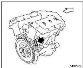
natural_image
Technical line drawing of an internal combustion engine (no text or labels)ENGINESERIALNUMBER
Thenumberisstampedontheengineas shown.
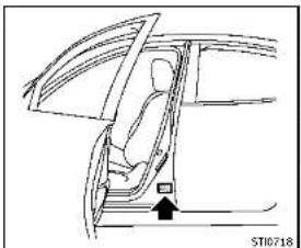
natural_image
Line drawing of a car interior showing seat, door, and window (no text or symbols)F.M.V.S.S./C.M.V.S.S.CERTIFICATIONLABEL
The Federal/Canadian Motor Vehicle Safety Standards (F.M.V.S.S./C.M.V.S.S.) certification labels are fixed based on this label contains valuable vehicle information, such as: Gross Vehicle Weight Ratings (GVWR), Gross Axle Weight Rating (GAWR), month and year of manufacture, Vehicle Identification Number (VIN), etc. Review it carefully.
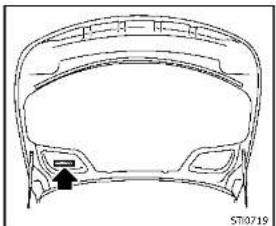
natural_image
Technical line drawing of a car head panel with no visible text or symbolsEMISSIONCONTROLINFORMATION
LABEL
The emission control information label is attached as shown.
9-12Technicalandconsumerinformation


natural_image
Line drawing of a car interior showing a person seated inside the dashboard and wheel (no text or symbols)TIREANDLOADINGINFORMATION LABEL
ThecoldtirepressureisshownontheTire andLoadingInformationlabelaffixedto thepillarasillustrated.

natural_image
Technical line drawing of a car body panel with no visible text or symbolsAIRCONDITIONERSPECIFICATION LABEL
Theairconditionerspecificationlabelis attachedasshown.

Technicalandconsumerinformation9-13
INSTALLINGFRONTLICENSEPLATE

text_image
Step 5 Learne plate broked Step 4 Mounting holes Step 3 Fiat blade DRAW MATH Extracer DRAW ZIMM Extracer Rearve grauvets Step 2 Lift to pan DRAW MATH, where it and the hole. Step 1 Screw JV0222XUse the following step to mount the license plate: Before mounting the license plate, confirm that the following parts are enclosed in the plastic bag.
Only use there recommended mounting position, otherwise teradarsensor(Intelligent Cruise Control(ICC) system)(ifso equipped) obstruction may result.
●Licenseplatebracket
J-nut × 2
- Screw × 2
●Screwgrommet × 2 1. Parkthevehicleonflat, levelground.
- Locatethecenterposition ① as illustrated. Positionthelicenseplate bracketata distance of approximately 1.26in(32mm) ② fromthebottomof thebumper. Holdthelicenseplate bracketinplace
3.Markthecenterofthehole felt-tippen. © witha
- Carefully drilltwopilotholesusinga 0.35in(9mm)drillbitatthemarked locations.(Besurethatthedrillonly goesthroughthebumperfascia.)
9-14Technicalandconsumerinformation
REMOVINGAIRDEFLECTORS
- Insertgrommets into the hole on the fascia.
- Insertaflat-bladescrewdriver into the grommetholetoadd90°turnontothe part (D).
- Install the license plate bracket with screws.

text_image
A B ST10623Leftside
This vehicle is equipped with air deflectors in front of the front wheels. The deflectors will change the airflow to help improve aerodynamic performance.
Whentransportingyourvehicleonatrailer, theairdeflectorsmayinterlerewitha steepslopetoatrailerbed. Inthiscase, removethedeflectorsfromtheundercover ofthevehicle.
-
Loosenthreescrewsasshownand remove the left-side air deflector Ⓐ.
-
Tighten the removed screw Ⓑ in its original position.
-
Perform the same procedure to remove the right-side air deflector.
- Storethetwoairdeflectorsandfour screwstoreinstallinthereverseorder.
- When reinstalling, makesurealls six screws are firmly tightened on both hair deflectors.
Technicalandconsumerinformation9-15
VEHICLELOADINGINFORMATION

WARNING
-Itisextremelydangeroustoride inacargoareainsidethevehicle. Inacollision,peopleridingin theseareasaremorelikelytobe seriouslyinjuredorkilled.
- Donotallowpeopleorideinany area of vehicle that is not equipped with seats and seat belts.
- Besureeveryoneinyourvehicleis inaseatandusingaseatbelt properly.
TERMS
It is important to familiarize yourself with the following terms before loading your vehicle:
- CurbWeight(actualweightofyour vehicle)- vehicleweight including:standardandoptionalequipment,fluids,emergencytools,andsparetireassembly. This
weightdoesnotincludepassengersandcargo.
- GVW(GrossVehicleWeight)-curb weightplusthecombinedweight ofpassengersandcargo.
- GVWR(GrossVehicleWeightRating) - maximum total combined weightof the unloadedvehicle, passengers, luggage, hitch, trailer tongue load and any other optionalequipment. This informationislocatedontheF.M.V.S.S./C.M.V.S.S.label.
- GAWR(GrossAxleWeightRating)-maximumweight(load)limitspecified for the front or rear axle. Thisinformationislocatedonthe F.M.V.S.S./C.M.V.S.S.label.
- GCWR(GrossCombinedWeight Rating)-Themaximumtotal weightratingofthevehicle,passengers,cargo,andtrailer.
- Vehicle Capacity Weight, Load limit, Total load capacity - maximum total weight limit specified
otheload(passengersandcargo) for the vehicle. This is the maximum combined weight of occupants and cargothat can be loaded into the vehicle. If the vehicle is used to tow a trailer, the trail is tongue weight must be included as part of the cargoload. This information is located on the Tire and Loading Information label.
- Cargocapacity-permissible weight of cargo, the weight of totaloccupantsweightsubtracted fromtheloadlimit.
9-16Technicalandconsumerinformation
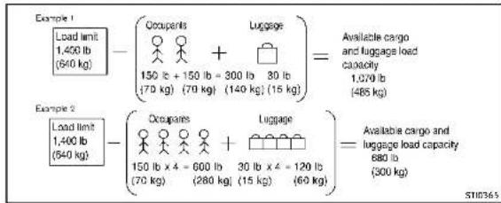
text_image
Example 1 Load limit 1,400 lb (640 kg) - (Occupants + Luggage) = Available cargo and luggage load capacity 1,070 lb (485 kg) 150 lb + 150 lb - 300 lb 30 lb (70 kg) (70 kg) (140 kg) (15 kg) Example 2 Load limit 1,400 lb (640 kg) - (Occupants + Luggage) = Available cargo and luggage load capacity 680 lb (300 kg) 150 lb x 4 = 600 lb 30 lb x 4 = 120 lb (70 kg) (280 kg) (15 kg) (60 kg)VEHICLELOADCAPACITY
Donotexceedtheloadlimitofyour vehicleshownas"Thecombined weightofoccupantsandcargo"on the Tire and Loading Information label. Donotexceedthenumber of occupantsshownas"SeatingCapacity"on the Tire and Loading Information label.
Toget "the combined weight of occupants and cargo", add the weight of allooccupants, then add
thetotalluggageweight.Examples areshownintheillustration.
Stepsfordeterminingcorrectload limit
-
Locatetheatement"Thecombinedweightofoccupantsand cargoshouldneverexceedXXXkg orXXXlbs"onyourvehicle's placard.
-
Determine the combined weight of the driver and passengers will be riding in your vehicle.
-
Subtract the combined weight of the driver and passengers from XXXkgorXXXlbs.
-
Theresultingfigureequalsthe availableamountofcargo and luggageloadcapacity. Forexample, iftheXXXamountequals 1400lbs.andtherewillbefive 150lb.passengersinyouvehicle, theamountofavailablecargo andluggageloadcapacityis650 lbs.(1400-750(5x150)=650lbsor640-340(5x70)=300kg.)
-
Determinethecombinedweightof luggageandcargobeingloaded onthevehicle.Thatweightmay notsafelyexceedtheavailable cargoandluggageloadcapacity calculatedinStep4.
-
If your vehicle will betowing a trailer, load from your trailer will be transferred to your vehicle. Consult this manual to determine how this reduces the available
cargoandluggageloadcapacity of your vehicle.
Beforedrivingloadedvehicle, confirmthatyoudonotexceedthe GrossVehicleWeightRating(GVWR) ortheGrossAxleWeightRating (GAWR)foryourvehicle.(See"Measurementofweights"(P.9-18).) Alsochecktiresforproperinflation pressures.SeetheTireandLoading Informationlabel.
LOADINGTIPS
- TheGVWmustnotexceedGVWR orGAWRassspecifiedontheF.M.V.S.S./C.M.V.S.S.certificationlabel.
- Donotloadthefrontandrearaxle totheGAWR.Doingsowillexceed theGVWR.

WARNING
•Properlysecureallcargotohelp preventitfromslidingorshifting. Donotplacecargohigherthanthe
seatbacks. In a sudden stop or collision, unsecured cargo could cause personal injury.
- Donotloadyourvehicle any heavierthantheGVWRorthe maximumfrontandrearGAWRs. Ifyoudo, partsofyourvehiclecan break, tiredamagecouldoccur, or itcanchangethewayyourvehicle handles. Thiscouldresultinloss ofcontrolandcausepersonal injury.
Overloadingcouldnotonlyshort-enthelifeofyourvehicleandthe tires,but alsocould lead to hazardous vehiclehandling and long braking distance.This may cause a premature tire malfunction,whichcouldresult in a seriousaccidentandpersonalinjury.Failurescausedbyoverloading are not covered by the vehicle's warranty.
MEASUREMENTOFWEIGHTS
Securelooseitemstopreventweight shiftsthatcouldaffectthebalanceof yourvehicle. When thevehicleis loaded,drivetoascaleandweigh thefrontandtherearwheelsseparately to determine axle loads. Individualaxle loads should not exceedeitherofthe grossaxle weightratings(GAWR). Thetotalof theaxleloadsshouldnotexceedthe grossvehicleweightrating(GVWR). Theseratingsaregiven onthe vehicle certificationlabel. If weight ratings are exceeded, move or removeitemstobringallweights belowtheratings.
9-18Technicalandconsumerinformation
TOWINGATRAILER
Donottowatralerwithyour vehicle.
FLATTOWING
Towingyourvehiclewithallfourwheelson thegroundissometimescalledflattowing. Thismethodissometimesusedwhen towingavehiclebehindarecreational vehicle,suchasamotorhome.

CAUTION
●Failuretofollowtheseguidelinescan resultinseveretransmissiondamage.
- Whenever flattowing your vehicle, al- waystowforward, never backward.
- DONOTtowanyAutomaticTransmission (AT)vehiclewithallfourwheelsonthe ground(flattowing).DoingsoWILL DAMAGEinternaltransmissionparts duetolackoftransmissionlubrication.
•DONOTtowanyAll-WheelDrive(AWD) vehiclewithanyofthewheelsonthe ground.Doingsomaycauseseriousand expensivedamagetothepowertrain.
- Foremergencytowingproceduresrefer to "TowingrecommendedbyINFINITI" (P.6-14).
AutomaticTransmission
All-WheelDrive(AWD)models:
DonottowanAWDvehiclewithanyofthe wheelsontheground.
Two-WheelDrive(2WD)models:
Totowavehicleequippedwithanautomatictransmission,anappropriatevehicle dollyMUSTbeplacedunderthetowed vehicle'sdrivewheels.Alwaysfollowthe dollymanufacturer'srecommendations whenusingtheirproduct.
UNIFORMTIREQUALITYGRADING
DOT(DepartmentOfTransportation)QualityGrades: Allpassengercartiresmust conformtofederalsafetyrequirementsin additiontothesegrades.
Qualitygradescanbefoundwhereapplicableonthetiresidewallbetweentread shoulderandmaximumsectionwidth. For example:
Treadwear200TractionAATemperatureA
TREADWEAR
The threadweargradeisacomparative ratingbasedonthewearrateofthetire whentestedundercontrolledconditions onaspecifiedgovernmentestcourse. For example, atiregaded 150 wouldwearone andone-half(11/2)timesaswellonthe governmentcourseasatiregraded 100. Therealive performancecofiresdepends uponacualconditionsoltheiruse, however, andmaydepartssignificantlyfrom the normduetovariationsindrivinghabits, servicepracticesanddifferencesinroad characteristicsandclimate.

Technical and consumer information
TRACTIONAA,A,BANDC
Thelractiongrades, from highest to lowest, are AA, A, Band C. Those grades represent the 'sability to stop on wet pavement as measured under controlled conditions on specified government test surfaces of asphalt and concrete. Atire marked C may have poor traction performance.

WARNING
Thetractiongradeassignedtothistireis basedonstraight-aheadbrakingtraction tests, and does not include acceleration, cornering, hydroplaning, or peaktraction characteristics.
TEMPERATUREA, BANDO
The temperature grades A (the highest), B, and C, representing the tire's resistance to the generation of heat and its ability to dissipate heat when tested under controlled conditions as specified indoor laboratory test wheel. Sustained high temperature can cause them material of the tire to generate and reduce tire life, and excessive temperature can lead to sudden
9-20Technicalandconsumerinformation
tirefailure. ThegradeCcorrespondstoa levelofperformancewhichallpassenger cartiresmustmeetundertheFederal MotorVehicleSafetyStandardNo.109. GradesBandArepresenthigherlevelsof performanceonthelaboratorytestwheel thantheminimumrequiredbylaw.

WARNING
Thetemperaturegradeforthistireis establishedforatirethatisproperly inflatedandnotoverloaded.Excessive speed,under-inflation,orexcessiveloading, eitherseparatelyorIncombination,can causeheatbuild-upandpossibletirefailure.

DEALER
EMISSIONCONTROLSYSTEMWARRANTY
Your INFINIT discovered by the following emission warranties.
ForUSA:
- EmissionDefectsWarranty - EmissionsPerformanceWarranty Detailsofthesewarrantiesmaybefound withother vehiclewarrantiesinyour WarrantyInformationBookletthatcomes withyourINFINITI.Ifyoudidnotreceive a WarrantyInformation Booklet,or it has becomelost,youmayobtainareplacementbywritingto:
• INFINITIDivision NissanNorthAmerica,Inc ConsumerAffairsDepartn P.O.Box685003 Franklin.TN37068-5003
ForCanada:
EmissionControlSystemWarranty Details of these warranties may be found with other vehicle warranties in your Warranty and Roadside Assistance Information that comes with your INFINIT. If you did not receive a Warranty and Roadside Assistance Information, or has become lost, you may obtain are placement by writing to:
●NissanCanadInc. 5290OrbitorDrive Mississauga,Ontario, L4W4Z5
REPORTINGSAFETYDEFECTS
ForUSA
If you believe that your vehicle has a defect which could cause crash or could cause injury or death, you should immediately inform the National Highway Traffic Safety Administration (NHTSA) in addition to notifying INFINITI.
IfNHTSAreceivessimilarcomplaints, itmayopenaninvestigation, andifit findsthatasafetydefectexistsina groupofvehicles, itmayordera recallandremedycampaign. However, NHTSAcannotbecomeinvolved in individualproblemsbetweenyou, yourretailer, orINFINITI.
TocontactNHTSA,youmaycallthe VehicleSafetyHotlinetoll-freeat1-888-327-4236(TTY:1-800-424-9153);gotohttp://www.safercar.gov;orwriteto:Administrator, NHTSA, 400 Seventh St&Wt, Washington DC 20590. You can also obtain other information about motor vehicle safety from http://www.safe-
rcar.gov.
YoumaynotifyINFINITIbycontacting ourConsumerAffairsDepartment, toll-free, at1-800-662-6200.
ForCanada
If you believethat your vehicle has a defect which could cause acrashor could cause injury or death, you should immediately inform Transport Canada in addition to notifying INFINITI.
IfTransportCanadareceivescomplaints, itmayopenaninvestigation, andifitfindsthatasafetydefect existsinagroupofvehicles, itmay requestthatINFINITIconductarecall campaign. However, TransportCanada cannot become involved in individual problems between you, your retailer, or INFINITI.
YoumaycontactTransportCanada's DefectInvestigationsandRecalls Divisiontollfreeat1-800-333-0510. Youmayalsoreportsafetydefects
Technical and consumer information 9·21
onlineat:
https://wwwapps.tc.gc.ca/Saf-Sec-Sur/7/PCDB-BDPP/Index.aspx.
Additional information concerning motorvehiclesafety maybeobtained from Transport Canada's Road Safety Information Centreat 1-800-333-
0371oronlineatwww.tc.gc.ca/roadsafety(Englishspeakers)or www.tc.gc.ca/securiteroutiere (Frenchspeakers).
TonotifyINFINITlofanysafetyconcernspleasecontactourConsumerInformationCentretollfreeat1-800-361-4792.
READINESSFORINSPECTION/MAINTENANCE(I/M)TEST(USonly)
WARNING
AvehiclequippedwithIntelligentAll-WheelDrive(AWD)shouldneverbeleted usingatwowheeldynamometer(suchas the dynamometersusedbysomestatesfor emissionstesting),orsimilarequipment. Makesureyouinformtestfacilitypersonnel thatyouvrheiclesequippedwithAWD before it is placed on a dynamometer. Using the wrongtestequipmentmayresultin transmission damage or unexpected vehicle movementwhichcouldresultinserious vehicledamageopersonalinjury.
Duetolegalrequirementsinsomestates/areas,yourvehiclemayberequiredtobe inwhatiscalledthe"readycondition"for anInspection/Maintenance(I/M)testof theemissioncontrolsystem.
The vehicle is set to the "ready condition" when it is driven through certain driving patterns. Usually, the "ready condition" can be obtained by ordinary usage of the vehicle.
If a powertrain system component is repaired or the battery is disconnected, the vehicle may be reset to a "not ready
condition".Beforetakingthel/Mtest, check the vehicle's inspection/maintenanceetestreadinesscondition.Piacethe ignitionswitchintheONpositionwithout startingtheengine.IftheMalfunction IndicatorLight(MIL)comesonsteadyfor 20 seconds and then blinks for 10 seconds,thel/Mtestconditionis"not ready".IfheMiI does not blinkafter 20 seconds, the I/M test condition is "ready". ContactanINFINITretailertosetthe "ready condition" or to prepare the vehicle fortesting.
9-22Technicalandconsumerinformation
EVENTDATARECORDERS(EDR)
ThisvehicleisequippedwithanEventData Recorder(EDR).Themainpurposeofan EDRistorecord, incertaincrashornear crash-likesituations, suchasanairbag deploymentorhittingaroadobstacle, data that willassistinunderstandinghowa vehicle'ssystemperformed. The EDRis designedtorecorddatarelatedtovehicle dynamicsandsafetysystemsforashort periodoftime, typically30secondsor less. The EDRinthisvehicleisdesignedto recordsuchdataas:
- Howvarious systems in your vehicle were operating;
- Whetheromotthedriverandpassengersafetybeltswerebuckled/fastened;
■Howfar(ifatall)thedriverwas depressingtheacceleratorand/or brakepedal;and,
- Howfastthevehiclewastraveling. - Soundsarenotrecorded.
Thesedatacanhelpprovideabetter understandingofthecircumstancesin whichcrashesandinjuriesoccur.
NOTE:EDRdataarerecordedbyyour vehicleonlyifanontrivialcrashsituation occurs;nodataarerecordedbytheEDR undernormaldrivingconditionsandno personaldata(e.g.name,gender,ageanc
crashlocationarerecorded. However, otherparties, suchaslawenforcement, couldcombinetheEDRdatawiththetype ofpersonallyidentifyingdataroutinely acquiredduringacrashinvestigation. ToreaddatarecordedbyanEDR, special equipmentsrequiredandaccessstothe vehicletheEDRisneeded. Inadditionto thevehiclemanufacturer and INFINITI retailer,otherparties,suchaslawenforcement,thathavethespecialequipment,can readtheinformationiftheyhaveaccesso thevehicleortheEDR.EDRdatawillonty beaccessedwiththeconsentofthevehicle ownerolesseesorasotherwiserequiredor permittedbylaw.

OWNER'SMANUAL/SERVICEMANUAL ORDERINFORMATION
GenuineINFINITServiceManualforthis modelyearandpriorcanbepurchased.A genuineINFINITServiceManualisthebest sourceofserviceandrepairinformationfor yourvehicle.Thismanualisthesameone usedbythefactory-trainedtechnicians workingatINFINITretailerships.Genuine INFINITIOwner'sManualscanalsobe purchased.
ForUSA:
For current pricing and availability of genuine INFINITIService Manuals, contact:
1-800-450-9491 www.infiniti-techinfo.com
For current pricing and availability of genuine INFINITI Owner's Manuals, contact:
1-800-247-5321
ForCanada:
TopurchaseacopyofagenuineINFINITI ServiceManualorOwner'sManualforth is modelyearandprior,contactanINFINITI retailer.Forthephonenumberandlocation ofanINFINITIretailerinyourareacallthe INFINITISatisfactionCenterat1-800-361-4792andabilingualINFINITIrepresentativewillassistyou.
Technical and consumer information
MEMO
9-24Technicalandconsumerinformation

Information Provided by: DEALER
10Index
A
ABS(Anti-lockBrakingSystem)....5-107
ActiveLaneControl 5-24
Activetracecontrol....5-110
Airbagsystem
Front-sealmountedside-impact
supplementalairbagsystem....1-52
Roof-mountedcurtainside-impact
supplementalairbagsystem....1-52
Airbagwarninglabels....1-55
Airbagwarninglight....1-55,2-16
Aircleanerhousingfilter.
Airconditioner
Airconditionerspecificationlabel....9-13
Airconditioningsystemrefrigerantand
lubricantrecommendations....9-7
Airdeflectors....9-15
Alarm
Howtostopalarm(seevehicle
securitysystem)....2-32
Alcohol, drugs and driving....5-9
Antenna 4-3
Anti-lockBrakingSystem(ABS)....5-107
Арреагансосаге
Exteriorappearancecare....7-2
Interiorappearancecare....7-5
Armrest....1-7
Ashtrays....2-44
Audiblereminders....2-19
Autolightsystem 2-37
Automatic
Automatictransmissionfluid(ATF)....8-12
Drivingwithautomatictransmission....5-15
Automatic doorlocks....3-5
Automaticdrivepositioner....3-29
Automaticmoonroof....2-51
Automaticseatpositioner....3-29
Averagespeed 2-28
Avoiding collision and rollover....5-8
B
Back-upCollisionIntervention(BCI)system.....5-48
Battery....8-15
Batteryreplacement.IntelligentKey....3-2
Batterysaversystem....2-40
IntelligentKey....8-24
Variablevoltagecontrolsystem....8-17
Beforestartingtheengine....5-13
Bells(Seodrivebelts)....8-17
BlindSpotWarning(BSW)system/BlindSpot
Intervention ^TM (BSI)system....5-37
Brake
Anti-lockBrakingSystem(ABS)....5-107
Brakefluid....8-13
Brakeforced distribution 5-109
Brake system 5-106
Parking brake operation 5-20
Brake warning light 2-13
Break-in schedule 5-99
Bulbcheck/instrumentpanel....2-12
Bulbreplacement....8-26
C
Capacities and recommended fuel/lubricants.....9-2
CarphoneonCBradio....4-3
Cardholder....2-47
Catalyticconverter
Three-waycatalyst....5-4
Chassiscontrol....5-112
Checkfirepressurewarning....2-23
Childrestraints....1-24
LATCHsystem....1-26
Precautionsonchildrestraints....1-24
Childsafety....1-22
Childsafetyreardoorlock....3-6
Chimes
Audiblereminders....2-19
Sealbeltwarninglightlandchime....2-16
Circuitbreaker
Fusiblelink....8-22
Cleaningexteriorandinterior....7-2,7-5
Clock 2-30
Coathooks 2-48
Cockpit....2-3
Coldweather driving....5-112
Compact Spare tire....B-40
Compass....2

Coolant
Capacitiesand
recommendedfuel/lubricants....9-2
Changingengine coolant....8-9
Checkingenginecoolantlevel....8-9
Corrosion protection....7-7
Courtesy 2-56
Cruisecontrol....5-56
Fixedspeedcruisecontrol(aniCCsystem)...5-74
IntelligentCruiseControl(ICC)system....5-5B
Cruise indicator....2-24
Cupholders....2-44
Currentfuelconsumption....2-28
D
Daytimerunninglightsystem....2-40
Delrosterswitch
Rearwindowandoutsidemirror
defrosterswitch....2-36
Dimensions....9-1
Directadaptivesteering....5-104
DistanceControlAssist(DCA)system....5-79
Distancetoempty....2-28
Drivebelts....8-17
Drivepositioner....3-29
Driverassisystemindicator....2-25
Driving
Coldweatherdriving....5-112
Drivingwithautomatictransmission....5-15
Precautionswhenstartinganddriving....5-3
E
ECOdriveindicatorlight....2-17
ECOmade 5-22
ECOpedalsystem....5-22
Economy
Fuel \$-100
Lispechine....7-78
Elapsectimed-tripodometer....2-28
Emission control information label....9-12
Emissioncontrolsystemwarranty....9-20
Engine
Beforestartingtheengine....5-13
Break-inschedule 5-99
Capacitiesand
recommendedfuel/lubricants....9-2
Changingenginocoulant....8-9
Changingengineoilandfilter 8-10
Checkingengineapolantlevel 8.0
Checkingengineoilval 8:10
Coolanttemperaturegauge 2.8
Emergency check cutoff 5-17
Engineblockheater 5-113
Engineering, analyst check locations 8-5
Enginecoatingsystem B-R
Engiopoil B-10
Enging oil and filter replacement indicator... 2.26
Engine oil and oil filter recommendation 9-6
Engine oil viscosity 9-7
Engine serial number 9-12
Engine specifications 9-8
Enginestarloperationindicator....2-22
Ilyourvehicleoverheats....6-12
Startingtherengine....5-14
Enginecoolanttemperaturegauge....2-8
Entry/exitfunction
Automaticdrivepositioner....3-29
EventDataRecorders(EDR)....9-23
Exhaustgas(carbonmonoxide)....5-3
F
F.M.V.S.S./C.M.V.S.S.certificationlabel....9-12
Filter
Aircleanerhousingfilter....8-19
Changingengineoilandfilter....8-10
shers(Seehazardwarningflasherswitch).....6-2
Flattire....6-3
FlatTire-Visitdealerwarning....2-23
Flattowing....9-1
Floormatecleaning....7-6
Floomatpositioningaid....7-6
Fluid
Automatictransmissionfluid(AIF)......8-12
Brakefluid 8-13
Capacitiesand
recommendself/lubricants 9-2
Γριπορολατ 8.4
Enginopil 8-10
Powerstearingfluid 9-13
Windowwasherfluid 8-14
Englishswitch 7-47
Forwardemergencybrakingsystem....5-89
Forwardemergencybrakingsystem
warninglight....2-13
Frontpassengerairbagandstatuslight......1-49
Frontpowerseat adjustment....1-3 Frontseat
Frontseatadjustment....1-3
Fuel
Capacitiesand
recommendedfuel/lubricants....9-2
Fuel economy....5-100
Fuelinformation....9-4
Fueloctanerating....9-4
Fuel-fillercap....3-21
Fuel-filterdoor....3-21
Gudge....2 FuelEfficientDrivingTips....5-99
Fuses....8-27
Fusiblelinks....B-22
G
Garagedooropener
HomeLink ^® Universaltransceiver......2-56
Gascap....3-21
Gauge....2-6
Enginecoolanttemperaturegauge....2-8
Fuelgauge....2-9
Gabmeter....2
Sjotho-Hefer 2
Tachronieter....2-
Generalmaintenance....8-2
Glovebox....2-46
H
Hazard warning flasherswitch....6-2
Headrestraints/headrests....1-8
Headlights
Aimingcontrol(SeeAdaptiveFrontlighting
System(ATS)....2-40
Headlightswitch....2-36
ated seats....1-5
ater
Engineblockheater....5-113
Hobemassist....2-38
startassistsystem....5-111 met link® UniversalTranscetiver 7-56
TRELINK UNIVERSITHEISCENER 2-30 admiraten 3-18
adrechase..../ta ak
cp
Trunkbooks 2-49
- 2-42
1
Ignitionswitch
(Push-button)....5-10
Automatictransmissionmodels....5-15
nobilizer system 2-3
icator
Lights 2-17
Vehicle information display 2-20
Indicator lights 2-17
Indicatorslooperation(vehicle
informationdisplay)....2-22
INFINITIDriveMadeSelector....5-21
InfinitInTouchOwner'sManual....4-2
INFINITVehicleImmobilizer System....2-32
Enginestart....2-32
Insidermirror....3-26 inversion(maintenance(1/50)test....8-27
inspection; maintenance(1; 9) test....9-22
Instrument brightness control....2-41 Instrument panel....2-5
Intelligent(All-Wheel)Drive(AWD) 5-101
IntelligentCruiseControl(ICC)system....5-58
IntelligentCruiseControl(ICC)system
ONindicator....2-24
IntelligentKey....3-2
IntelligentKeysystem....3-6
Batteryreplacement....8-24
Keyoperatingrange....3-8
Keyoperation....3-9
Warningsignals....3-12
interiorightcontrolswitch....2-54 interiorlightreplacement....0.27
Interiorlightreplacement....8-27 Interiorlights....3-52
interiortrunklidrelease 3-21
150FIXchildrestraint 1-26
)
lumpstarting....6-9
K
Keylessentry(Soeremotakeyless
entrysystem)....3-14
Keys....3-2
For Intelligent Keysystem....3-6
L
Labels
ArdiagWarningGlauers....1-35
AconditionanerFastingLabel....0-12
Emission control information label 9.12
Engineserialnumber....9-12
F.M.V.S.S./C.M.V.S.S.certificationlabel.....9-12
TireandLoadinginformationlabel.....8-30,9-13
LaneDeparturePrevention(LDP)system....5-33
LaneDepartureWarning(LDW)system....5-31
LaneDepartureWarning(LOW)system/Lane
LATCHsystem....1-26
Licenseplate
Installingfrontlicenseplate....9-14
Airbagwarninglight....1-55
Bulbreplacement....8-26
ToglightS/NHL 2-42
Indicatorlights 2.17
Interiorlightcontrolswitch....2-54
Interiorlights....2-53
Maplights....2-53
Personallights....2-54
Replaciment......8-76 Treadlight......2.65
Vanitymirrorlights....2-55
Warning/indicatorlightsand
audiblereminders....2-12
Lights
Exterior and interior light replacement.....8-27
leadinginformation) 9-16
Lack
Automatic doorlocks....3-5
Doorlocks....3-4
POKESONHOCK....34 Taviklid....7.49
Lockingwithmechanicalkey....3-4
Log-infunction....3-14
LooseFuelCapWarning....2-23,3-23
Lawful warning light....2-14 Lawoutsidotampraturwarming....2-26
Lowtinepressurewarpinglight 2-14
Lowtirepressurewarmingsystem
(See TirePressureMonitoring
System(TPMS)....5-4,6-3,8-29
M
Maintenance
Battery 8-15
General maintenance 8-2
Indicators for maintenance vehicle
informationdisplay)....2-25
Insidethevehicle....B-3
Maintenance precautions....8-5
Maintenance requirements....8-2 Outside vehicle....8-1
Seatbeltmaintenance 1-71
Underthehood and vehicle....8-4
Malfunctionindicatorlight(MIL)....2-18
Maplights 2-53
Masterwarninglight....2-16
MecAzn:Alakey(Intelligent System)....3-1
Memory storage Automaticdrivenpositioner....3-30
Meter
Tripcomputer....2-28
Meters and gauges....2-6
instrumenting thickness control....2-41
Insidermirror 3-26
Outsidemirrors....3-27
Vanitymirror....3-29
Moenroof 2-51
N
NAV|ShiftControl....5-19
Newvehiclebreak-in....5-99
0
Odometer 2-7
Off-roadrecovery....5-8
Oil
Capacitiesand
recommendedfuel/lubricants....9-2
Changingengineoilandfilter....8-10
Checkingengineoillevel....8-10
Engineoil....8-10
Engineolviscosity....9-7
Onelouchunlocksensor(Seelntelligent
Keysystem)....3-9
Operation
Indicatorsforoperation....2-22
Outside air temperature....2-30
Outsidemirrors....3-27
Overheat, If your vehicle overmeats....6-12
Owner: s'manual, Servicemanual
orderinformation....9-23
P
Paricalarm....3-16
Parking
Parkingbrakeoperation....5-20
Parkingonhills....5-103
Parkingbrakebreak-in....5-106
Personallights....2-14 PERSONAL roads....5-23
PERSONAL FIDDE....9-73
Fluor Carnhoeer/ Brodie 0.3
Power
cautions Banking recommendations 5.106
Braking precautions....5-106 Childrestraints 1-74
Children's 1-24 Cruiservcontrol 5-56
Landopardur warning(LDW) system....S-31
Maintenance....8-9
PrecautionsonBCIsystem....5-53
Seatbeltusage....1-12
Supplementalrestraintsystem....1-42
Whenstartinganddriving....5-3
Pre-crashseatbeltswithcomfortfunction.....1-14
Predictiveforwardcollisionwamingsystem.....5-94
Pushstarting....6-11
Push-buttonignitionswitch....5-10
R
Radio
Carphone/CBradio....4-3
Rain-sensingautowlpersystem....2-35
Rapidairpressureloss....5-9
Readinessforinspection/maintenance(I/M)test
(US only) 9-22
Keardban och
Child safety rear door lock 3-6
Rear seats 1-5
Rearwindowandoutsidemirror
defrosterswitch....2-36
Recorders
Eventdata....9-23
Registering your vehicle in another country.....9-11
Remotekeylessentrysystem....3-14
Reportingsafetydefects....9-21
Requestswitch(See IntelligentKeysystem)......3-9
Roadsideassistanceprogram....6-2
Rolla
Roof
Maonrapf....2-52
5
Safety
Childsnatbells....1-22
Reportingsafetydeferts....9-21
Seatadjustment
Frontpowerseatadjustment....1-3
Frontseats....1-3
atbelt(s)
Childsafety....1-22
Infants....1-23
Injuredpersons....1-14
Largerchildren....1-23
Preciseous health insurance....1-12
Pre-crashseatbetiswincomfortfunction...1-14
Pregnantwomen....1-14
Seathelteerling....7-7 Seathelteernders....1.21
Seatbeltmaintenance....1-21
Seatbeltwaminglightandchime....2-16
Seatbelts....1-12
Seatbeltwithpreensions....1-94 Shoulderbeltheightadjustment 1-20
Smallchildren....1-23
Three-pointtype....1-15
Seat(s)
Driver-sidermemory....3-29
Healedseals....1-5 Soats....1-7
Securitysystem
Vehiclesecuritysystem....2-31
Securitysystem(INFINITVehicleImmobilizer
System)
Enginestart....2-32 Shiftlower
Shintever Sniffverkursorge 5-12
Shiftlockrelease....5-18 Shiftlockrelease.Transmission....5-18
Shifting
Automatictransmission....5-15
Shoulderbeltheightadjustment....1-20
SNOWmode....5-22
Sparetle 9-9 Sparkups 8-12
Sparkstags....0-10 Sperdometer....2-7
SPORTmode....5-22
STANDARDmade....5-21
Starting
Before starting the engine....5-13
jumpstarting....8-16
Precautionswhenstartinganddriving....5-3
Pushstarling....6-11
Startingthoengine....5-14
Statuslight, Frontpassengerairbag......1-49
Steering
Directadaptivesteering....5-104
Powersteeringfluid....8-13
Powersteeringsystem....5-104
Till/telescopicsteering....3-24
Storage: 7-2 Storagebox: 2-47
Sunvisors 3-25
Sunglassesholder....2-46
Supplementalairbagwarninglabels....1-55
Supplementalairbagwarninglight.....1-55,2-16
Supplementalrestraintsystem....1-42
Precautionsonsupplemental
restrainlsystem....1-42
Switch
Autolightswitch....2-37
Foglightswitch....2-42
Hazardwarningflasherswitch....6-2
Headlightswitch....2-36
Ignitionswitch....5-15
Rearwindowandoutsidermirror
defresterswitch....2-36
Turn signal switch.... 7-42
Vehicle Dynamic Control (VDC) off switch ..... 2-43
T
Tachometer....2-8
Temperaturegauge
Enginecoolanttemperaturegauge....2-8
Theft(INFINITVehicleImmobilizerSystem)
Enginestart....2-32
Thighextension....1-5
Three-waycatalyst....5-4
Hitt/telescopicsteering....3-24
the
FlatTire-Visitdealerwarning....2-23
Run-flattires....6-4
Tirereplacementindicator....2-26
Ilerotation....8-37
Tirepressure
Lowtirepressurewarninglight....2-14
TirePressureLow-AddAirWarning....2-23
tires
Flattire 6-3
Lowtirepressurewarningsystem...5-4,6-3,8-29
Run flatties....8-35
Sparetire....8-40
TireandLoadinginformationlabel.....8-30,9-13
Tirechains....8-36
Tiredressing....7-4
Tirepressure....8-29
TirePressureMonitoring
System(IPS)....5-4,6-3,8-29
Typesoltires....8-34
Uniformtirequalitygrading....9-19
Wheel/tiresize....9-9 Wheelsandtires....8-29
Towing Flattowing....9-19 Towtrucktowing....6-13 Towingatraler....9-19
TPMS TirePressureMonitoringSystem....5-4,6-3,8-29 TPMS,Tirepressuremonitoringsystem TPMSwithTireInflationIndicator.....5-7
Trailerbowing....9-19 Transceiver HomeLink® UniversalTransceiver....2-56 Transmission Automatictransmissionfluid(ATF)....8-12 Drivingwithautomatictransmission....5-15 Transmissionshiftleverlockrelease....5-18
Transmitter(Seeremotakeylessanlrysystem)...3-14 Travelingorregisteringyourvehiclein anothercountry....9-11 Tripcomputer....2-28 Tripodometer....2-28 Trunk
Interiortrunklidrelease....3-21 Light....2-55 Pass-through....1-7 Trunkhooks....2-48 Trunklid....3-19 Trunklidreleaseswitch....3-19 Trunkopenrequestswitch....3-19 Trunkreleasepowercancelswitch....3-20
Turnsignalswitch....2-42
U
Underbodycleaning....7-3 Uniformtirequalitygrading....9-19
V
Vanitymirror....3-29 Vanitymirrortights....2-55 Variablevoltagecontrolsystem....8-17 Vehicle
Dimensions....9-10 Recovery(freeingastuckvehicle)....6-16 VehicleDynamicControl(VDC)offswitch....2-43 VehicleDynamiccontrol(VDC)system....5-108 VehicleDynamicControl(VDC) warninglight....2-17
Vehicleidentificationnumber(VIN)....9-11 Vehicleinformationdisplay....2-20 Vehicleloadinginformation....9-16 Vehiclesecuritysystem....2-31 Ventilators....4-7
W
Warning Blind Spot Warning (BSW) system.... 5-38 Flat Tire · Visit dealer warning .... 2-23 Hazard warning flasher switch.... 6-2
Indicators/operation(vehicle information/display)....2-22 LaneDepartureWarning(LDW):system....5-31 Lights....2-12 Powersteeringwarninglight....2-16 Predictiveforwardcollision warningsystem....5-94 TirePressureMonitoring System(TPMS)....5-4,6-3,8-29 VehicleInformationdisplay....2-20 Warning/Indicatorlightsand audiblerominders....2-12
Warninglabels Airbagwarninglabels....1-55
Warninglight Airbagwarninglight....1-55,2-16 Ant-lockbrakingsystem(ABS) warninglight....2-1 Brakewarninglight....2-13 Forwardemorgencybrakingsystem warninglight....2-1 Lowfuelwarninglight....2-14 Lowtirepressurewarninglight....2-14
Warranty Emission control system warranty....9-20 Washerswitch Windshield viper and washerswitch....2-33 Washing....7- Waxing....7- Wheel, tiresize....9-9
Wheelsandtires....8-79
Careolwheels....7-1
Cleaningaluminumallywheels..../-1
Cleaningoughwiths....7-4 Windowwasherfluid 8-10
Window(s)
Cleaning....7-3
Powerwindows....2-49
Windshieldwiperandwasherswitch....2-33
Wiper Rain-soning water/winter system 2.35
Windshieldwingsrandwashswitch 2-31
Wiperblades 8-20
MEMO

Information Provided by: DEALER
10-9
GAS STATION INFORMATION
FUELINFORMATION:
Useunleadedpremiumgasolinewithan octaneratingofatleast91AKI(Anti-Knock Index)number(Researchoctanenumber 96).
If unleaded premium gasoline is not available, unleaded regular gasolinewith an octanerating of 87AKInumber (Research octanenumber91) maybe temporarily used, but only under the following precautions:
- Havethefueltankfilledonlypartially withunleadedregulargasoline,andfill upwithunleadedpremiumgasolineas soonaspossible.
- Avoidfullthrottledrivingandabrupt acceleration.
Useunleadedpremiumgasolineformax- imumvehicleperformance.

CAUTION
- Usingafuelotherthanthatspecified couldadverselyaffecttheemission controlsystems,andmayalsoaffect warrantycoverage.
■Undermocircumstanceshouldaleaded gasolinebeused, because this will damagethethreewaycatalyst.
- DonotuseE-15orE-85fuelInyour vehicle.Youvehcleisnotdesignedto runonE-15orE-85fuel.UsingE-15orE-85fuelinavehiclenotspecifically designedforE-15orE-85fuelcan adverselyaffecttheemissioncontrol devicesandsystemsofthevehicle. Damagecausedbysuchfuelsnot coveredbytheINFINITnewvehicle limitedwarranty.
•U.S. government regulations require ethanoldispensingpumpstobeldentifiedbyasmall,square,orangeandblack labelwiththecommonabbreviationor theappropriatepercentageforthat region.
Foradditionalinformation,see"Capacities andrecommendedfuel/lubricants"(P.9-2).
ENGINEOILRECOMMENDATION:
●GenuineNISSANengineoilorequivalent
- EngineoilwithAPICertificationMark - ViscositySAESW-30
See "Capacitiesandrecommendedfuel/lubricants"(P.9-2)forengineoilandoil filterrecommendation.
COLDTIREPRESSURES:
The label is typically located on the driver sidecenterpillaronthedriver'sdoor. Foradditionalinformation,see"Wheels andtires"(P.8-29).
NEWVEHICLEBREAK-INPROCEDURE DURESRECOMMENDATION:
During the first 1,200 miles (2,000 km) of vehicleuse, followtherecommendations outlinedinthe"Break-inschedule"(P.5-99)ofthisOwner'sManual.Followthese recommendations forthefuture reliability andeconomyofyournewvehicle.

INFINITI.

DEALER