DirectNET CDI2528IW - Security Camera Costar - Free user manual and instructions
Find the device manual for free DirectNET CDI2528IW Costar in PDF.

User questions about DirectNET CDI2528IW Costar
0 question about this device. Answer the ones you know or ask your own.
Ask a new question about this device
Download the instructions for your Security Camera in PDF format for free! Find your manual DirectNET CDI2528IW - Costar and take your electronic device back in hand. On this page are published all the documents necessary for the use of your device. DirectNET CDI2528IW by Costar.
USER MANUAL DirectNET CDI2528IW Costar
Before reading this manual
This is a basic operation manual for use of a network camera. Users who are using this product for the first time, as well as users with experience using comparable products, must read this operation manual carefully before use and heed to the warnings and precautions contained herein while using the product. Safety warnings and precautions contained in this operation manual are intended to promote proper use of the product and thereby prevent accidents and property damage and must be followed at all times. Once you have read this operation manual, keep it at an easily accessible location for future reference.

- The manufacturer will not be held responsible for any product damage resulting from the use of unauthorized parts and accessories or from the user's failure to comply with the instructions contained in this manual.
- The information in this document is believed to be accurate as of the date of publication even though explanation about some functions may not be incorporated. The manufacturer is not responsible for any problems resulting from the use thereof. The information contained herein is subject to change without notice. Revisions or new editions to this publication may be issued to incorporate such changes.
- It is recommended that first-time users of this network camera and individuals who are not familiar with its use seek technical assistance from their retailer regarding product installation and use.
- If you need to disassemble the product for functionality expansion or repair purposes, you must contact your retailer and seek professional assistance.
- Both retailers and users should be aware that this product has been certified as being electromagnetically compatible for commercial use. If you have sold or purchased this product unintentionally, please replace with a consumer version.
Safety Symbols
| Symbol | Publication Description | |
| --- | IEC60417, No.5031 | Direct current |
In-Text
| Symbol | Type Description | |
 | Caution | Important information concerning a specific function. |
 | Note | Useful information concerning a specific function. |
Safety Precautions
WARNING
RISK OF ELECTRIC SHOCK
DO NOT OPEN
WARNING: TO REDUCE THE RISK OF ELECTRIC SHOCK,
DO NOT REMOVE COVER (OR BACK).
NO USER-SERVICEABLE PARTS INSIDE.
REFER SERVICING TO QUALIFIED SERVICE PERSONNEL.
Important Safeguards
1. Read Instructions
All the safety and operating instructions should be read before the appliance is operated.
2. Retain Instructions
The safety and operating instructions should be retained for future reference.
3. Cleaning
Unplug this equipment from the wall outlet before cleaning it. Do not use liquid aerosol cleaners. Use a damp soft cloth for cleaning.
4. Attachments
Never add any attachments and/or equipment without the approval of the manufacturer as such additions may result in the risk of fire, electric shock or other personal injury.
5. Water and/or Moisture
Do not use this equipment near water or in contact with water.
6. Placing and Accessories
Do not place this equipment on an wall or ceiling that is not strong enough to sustain the camera. The equipment may fall, causing serious injury to a child or adult, and serious damage to the equipment. Wall or shelf mounting should follow the manufacturer's instructions, and should use a mounting kit approved by the manufacturer.

This equipment and cart combination should be moved with care. Quick stops, excessive force, and uneven surfaces may cause the equipment and cart combination to overturn.
Do not place this equipment in an enclosed space. Sufficient ventilation is required to prevent an increase in ambient temperature which can cause malfunction or the risk of fire.
7. Power Sources
This equipment should be operated only from the type of power source indicated on the marking label. If you are not sure of the type of power, please consult your equipment dealer or local power company.
You may want to install a UPS (Uninterruptible Power Supply) system for safe operation in order to prevent damage caused by an unexpected power stoppage. Any questions concerning UPS, consult your UPS retailer.
This equipment should be remain readily operable.
8. Power Cord
Operator or installer must remove power and TNT connections before handling the equipment.
9. Lightning
For added protection for this equipment during a lightning storm, or when it is left unattended and unused for long periods of time, unplug it from the wall outlet and disconnect the antenna or cable system. This will prevent damage to the equipment due to lightning and power-line surges. If thunder or lightning is common where the equipment is installed, use a surge protection device.
10. Overloading
Do not overload wall outlets and extension cords as this can result in the risk of fire or electric shock.
11. Objects and Liquids
Never push objects of any kind through openings of this equipment as they may touch dangerous voltage points or short out parts that could result in a fire or electric shock. Never spill liquid of any kind on the equipment.
12. Servicing
Do not attempt to service this equipment yourself. Refer all servicing to qualified service personnel.
13. Damage requiring Service
Unplug this equipment from the wall outlet and refer servicing to qualified service personnel under the following conditions:
A. When the power-supply cord or the plug has been damaged.
B. If liquid is spilled, or objects have hit the equipment.
C. If the equipment has been exposed to rain or water.
D. If the equipment does not operate normally by following the operating instructions, adjust only those controls that are covered by the operating instructions as an improper adjustment of other controls may result in damage and will often require extensive work by a qualified technician to restore the equipment to its normal operation.
E. If the equipment has been dropped, or the cabinet damaged.
F. When the equipment exhibits a distinct change in performance — this indicates a need for service.
14. Replacement Parts
When replacement parts are required, be sure the service technician has used replacement parts specified by the manufacturer or that have the same characteristics as the original part. Unauthorized substitutions may result in fire, electric shock or other hazards.
15. Safety Check
Upon completion of any service or repairs to this equipment, ask the service technician to perform safety checks to determine that the equipment is in proper operating condition.
16. Field Installation
This installation should be made by a qualified service person and should conform to all local codes.
17. Tmra
A manufacturer's maximum recommended ambient temperature (Tmra) for the equipment must be specified so that the customer and installer may determine a suitable maximum operating environment for the equipment.
FCC Compliance Statement
THIS EQUIPMENT HAS BEEN TESTED AND FOUND TO COMPLY WITH THE LIMITS FOR A CLASS A DIGITAL DEVICE, PURSUANT TO PART 15 OF THE FCC RULES. THESE LIMITS ARE DESIGNED TO PROVIDE REASONABLE PROTECTION AGAINST HARMFUL INTERFERENCE WHEN THE EQUIPMENT IS OPERATED IN A COMMERCIAL ENVIRONMENT. THIS EQUIPMENT GENERATES, USES, AND CAN RADIATE RADIO FREQUENCY ENERGY AND IF NOT INSTALLED AND USED IN ACCORDANCE WITH THE INSTRUCTION MANUAL, MAY CAUSE HARMFUL INTERFERENCE TO RADIO COMMUNICATIONS. OPERATION OF THIS EQUIPMENT IN A RESIDENTIAL AREA IS LIKELY TO CAUSE HARMFUL INTERFERENCE, IN WHICH CASE USERS WILL BE REQUIRED TO CORRECT THE INTERFERENCE AT THEIR OWN EXPENSE.
WARNING: CHANGES OR MODIFICATIONS NOT EXPRESSLY APPROVED BY THE PARTY RESPONSIBLE FOR COMPLIANCE COULD VOID THE USER'S AUTHORITY TO OPERATE THE EQUIPMENT. THIS CLASS OF DIGITAL APPARATUS MEETS ALL REQUIREMENTS OF THE CANADIAN INTERFERENCE CAUSING EQUIPMENT REGULATIONS.
WEEE (Waste Electrical & Electronic Equipment)
Correct Disposal of This Product
(Applicable in the European Union and other European countries with separate collection systems)

This marking shown on the product or its literature, indicates that it should not be disposed with other household wastes at the end of its working life. To prevent possible harm to the environment or human health from uncontrolled waste disposal, please separate this from other types of wastes and recycle it responsibly to promote the sustainable reuse of material resources.
Household users should contact either the retailer where they purchased this product, or their local government office, for details of where and how they can take this item for environmentally safe recycling.
Business users should contact their supplier and check the terms and conditions of the purchase contract. This product should not be mixed with other commercial wastes for disposal.
This product contains software built partially on open-source content. You may obtain the complete corresponding source code depending on whether or not the source is publicly available under a license policy. For more information, refer to System > General page. This product includes software developed by the University of California, Berkeley and its contributors, and software developed by the OpenSSL Project for use in the OpenSSL Toolkit (http://www.openssl.org/). Also, this product includes cryptographic software written by Eric Young (eay@cryptsoft.com).
1
Part 1 - Remote Setup....7
Camera Protocol....7
Switching Protocols 7
Remote Setup....8
Quick Setup....9
System....9
General 9
Date/Time 10
User/Group 11
Network 12
IP Address 12
FEN....13
Port/QoS....14
Bandwidth Control 15
Security....16
IEEE 802.1X ......17
Video 17
Camera 18
Streaming 22
Webcasting 24
MAT 25
Privacy Masking....26
Event Action 26
Email 27
Remote Callback 27
FTP Upload 28
Record....29
Event 31
Motion Detection 31
Trip-Zone 32
Tampering 33
System Event 34
2
Part 1 - Remote Setup
Configure basic network camera settings and all other system settings.

Screen images may vary depending on the model.
Camera Protocol
Camera supports DirectNET™ and iNEX protocols.
- DirectNET™ protocol:
- Using with a DirectNET™ NVR enables camera use without the need to configure network settings.
- The DirectNET™ NVR also allows you to control all camera settings directly from the NVR, without the need for a computer.

For more information on configuring camera settings from a DirectNET™ NVR, refer to the DirectNET™'s operation manual.
- iNEX protocol:
- Control the camera over the network from software installed on a computer or a separate NVR.
- Ideal for using the camera over the network from a remote location.
Switching Protocols

text_image
INIT - Integrated Network Installation Tool Lookup Setup Test Reset Multiselection No Name 1 2 3 4 IP Address Setup Remote Setup WebGuard Apply Setup File Make Setup File IP Address 10.0.17.130 10.0.17.195 10.0.113.52 10.0.113.53
text_image
Protocol Setup Select Protocol : INEX OK Cancel1 Launch the INIT program and from the list, select a camera whose protocol you wish to change.
2 Click on the Setup 📄 icon and then select Setup → Protocol Setup.
• Alternatively, you can right-click on the mouse and select Protocol Setup.
3 From the Protocol Setup screen, select the desired protocol and then click OK.
4 This will activate the selected protocol. You can check each camera's protocol on the INIT program.

This user manual was written based on the iNEX protocol.
Remote Setup
1 Launch the INIT program and then from the main screen, select a network camera whose settings you wish to change.
2 Click on the Setup Icon.
3 Select Remote Setup from the Setup menu to load the Remote Setup screen. Alternatively, you can select Network Camera from the main screen and then right-click to access the Remote Setup screen.

- System settings can also be changed using a remote program.
- Remote Setup works with the following web browsers when the web browsers support HTML5: Microsoft Internet Explorer version 10 or later, Google Chrome, Mozilla Firefox, or Apple Safari. It may not work properly with Microsoft Internet Explorer version 9.0 or earlier. It is recommended that you update the web browser to the latest version. When you launch Remote Setup on a Microsoft Internet Explorer version 10 or later supporting HTML5 and the Remote Setup screen does not appear, check if the web browser's document mode is set to 9 or higher or Edge. You can check the document mode as follows: Press the F12 key on the keyboard → click the Document mode icon.

text_image
INIT - Integrated Network Installation Tool Lookup Setup Test Reset Multiselection IP Address Setup Remote Setup IP Address 1 WebGuard 10.0.17.130 2 Apply Setup File 10.0.17.195 3 Make Setup File 10.0.113.52 4 10.0.113.53
text_image
Quick Setup Information System Authority Video Systems Network Value Smart Action Smart Language: English Action Description: New User: Unknown/My/Other Preview: New - Edit 9 Preview: Default Name Category: Default/Residual Status: 0.000 Description: 1234 Application: 1234 (0) Quality: 1234 (0) Design Level: RGB Language code: 0.000 Settings: 0.000 Name: 1234 Name: 1234 Name: 1234From the Remote Setup screen, select the menu on the left to display the current settings. Select an option under the menu to change the corresponding settings. Once you have changed the settings, click Save to apply the settings.
Quick Setup

text_image
Quick Setup System Network Video System Network Video Event Action Event Quick Setup / Overview System: 1. Web App 2. Email 3. Text 4. Audio 5. Print 6. Print 7. Print 8. Print 9. Print 10. Print 11. Print 12. Print 13. Print 14. Print 15. Print 16. Print 17. Print 18. Print 19. Print 20. Print 21. Print 22. Print 23. Print 24. Print 25. Print 26. Print 27. Print 28. Print 29. Print 30. Print 31. Print 32. Print 33. Print 34. Print 35. Print 36. Print 37. Print 38. Print 39. Print 40. Print 41. Print 42. Print 43. Print 44. Print 45. Print 46. Print 47. Print 48. Print 49. Print 50. Print 51. Print 52. Print 53. Print 54. Print 55. Print 56. Print 57. Print 58. Print 59. Print 60. Print 61. Print 62. Print 63. Print 64. Print 65. Print 66. Print 67. Print 68. Print 69. Print 70. Print 71. Print 72. Print 73. Print 74. Print 75. Print 76. Print 77. Print 78. Print 79. Print 80. Print 81. Print 82. Print 83. Print 84. Print 85. Print 86. Print 87. Print 88. Print 89. Print 90. Print 91. Print 92. Print 93. Print 94. Print 95. Print 96. Print 97. Print 98. Print 99. PrintQuick Setup allows you to set up System, Network, Video, and other basic settings needed for camera use.
System

text_image
Quick Setup System General Language English Paper SMM/SW 1:1 / 1:0:0 OMAT Protocol On Data/Filter Data/Time Time Zone GMT (2:40) Eastern Time (US & Canada) (ECE) Time Sync Off UsageGroup UserGroup 1 / 3 Abitargets StartChange the camera's system information, add users/groups, and/or import/export settings.
General

text_image
Quick Setup System General SARCT FREE User/Group Network Video Event Action Event System / General Language Creation (Husatiki) Name: Name: Size: 01 Size: 110 Import Setup View Export Setup Import Setup Export Setup- Language: Select the language you wish to use for remote setup.
- Name: Enter a name for the camera. (Up to 31 alphanumeric characters, including spaces)
• Note: Enter a description for the camera. - HW Version/SW Version: Indicates the camera's hardware and software versions.
- Miscellaneous
- ONVIF Protocol: Select to enable ONVIF protocol use. However, ONVIF Protocol is available only to users belonging to the standard user groups (Administrator, Operator, and User) and when video compression is set to H.264 or JPEG under Video > Streaming menu. When you have connected to the camera by using the ONVIF protocol, only the currently enabled streams or events are supported and you cannot change it. There may be some more settings that cannot be changed, too. If you want to change those settings, connect to the camera by using the INIT program.
- Opensource Licenses: Click View to see the information of opensource licenses.
- Setup
- Load Default Setup: Restores all settings other than Date/Time to their factory defaults. Select Include Network Setup to load default network settings as well. For more information on network setup, refer to the Network on page 12.
- Import Setup: Open a setup file and apply its settings to the camera. Click on the button and then select a setup file. Select Include Network Setup to apply the file's network setup settings (exc. FEN). For more information on network setup, refer to the Network on page 12.
- Export Setup: Export the current settings as a file. Click on the button and then enter a file name.

- Load Default Setup and Import Setup options are available only to users belonging to the Administrator group.
- When applying the settings of a setup file, do not select the Include Network Setup option if the network settings contained in the selected file is currently being used by a different camera. Doing so can interfere with establishing a connection with the other camera.
- If IP Address, Port, and/or SSL settings have been changed, click Save to apply the current settings, and then restart Remote Setup. If you do not restart Remote Setup, the changes afterwards will not be applied.
Date/Time

text_image
Quick Setup Systems General Data/Time User/Group Networks Video Event Action Event System / Data/Time Data Time Date: 9916.08.08 ns Time: 17:23:30 Time Type: Shift-17:00 Foreword, Realspan Use Daylight Saving Time Time Type: Automatic Sync Time Details: Auto Tools Power: 50 ms. Size as Server Save- Date/Time: Change the camera's date/time settings and display formats and configure the time zone and daylight saving time settings. Click Save to apply the changes right away.
- Time Sync
- Automatic Sync: Select to synchronize the system's time with the time server at a specified interval. Enter the time server's IP address or domain name and then specify the interval. If the time server is FEN-enabled, select the Use FEN option and then enter the time server's name instead of its IP address or domain name.
- Run as Server: Select to run the camera as a time server. Other devices will then be able to synchronize its time setting with this camera's time setting.

If you wish to enter a domain name instead of an IP address for the Time Server setting, DNS server must be configured during Network setup. If you wish to enter a server name instead of an IP address or a domain name, the Use FEN option must be enabled during Network setup.
User/Group

text_image
Outk's Setup System General Data/Time User/Group Networks Video Event Action Event System / User/Group User/Group Add Group... Add User... Edit... Edit... Edit... Add User... Add User... Edit... Edit... All-Row Address User Save- User/Group: Change remote camera control permission settings for users and user groups.
- Add Group: Add a new user group. Designate a name for the group and then specify control authorities.
- Add User: Add a new user. Designate a name for the user, select which group to add the user to, and then enter a connection password.
- Edit: Edit group authorities and/or user passwords. Select a group or user and then click on the button.
- Remove: Delete groups or users. Select a group of user you wish to delete and then click on the button.
- Allow Anonymous Login: Select if you are using Webcasting. For more information on webcasting, refer to the Webcasting on page 24.

- User/Group settings can only be configured by users belonging to the Administrator group.
- There is no default password for the Administrator group's admin user.
- Standard groups (Administrator, Operator, and User) cannot be edited or deleted. Authorities assigned here apply identically to ONVIF protocol user groups.
- Group authorities that can be assigned are as follows:
- Upgrade: Upgrade the system.
- Setup: Configure the system's settings.
- Color Control: Adjust the camera's brightness, contrast, saturation, and hue settings.
- Search: Search video recordings saved on the SD memory card from a remote program.
- Clip-Copy: Search video recordings saved on the SD memory card and save them as video files from a remote program.
Network

text_image
Quick Setup System Networks IP Address FEN Port/OCT Bandwidth Control Security BEE MCLX Video Event Action Event Networks / Overview IP Address Type DHCP FTP Server FEN FEN Server - detamutLat Camera Name Port Sample Port 0006 WebGuard 80 RTSP 554 QPT (DASH) Sample Port 0 WebGuard 0 RTSP 0 Bandwidth Control Bandwidth Off Security IP Filtering Off USB OFF BEE MCLX SaveChange the network settings, enable FEN and security features, and control network bandwidth use.
IP Address

text_image
Quick Setup System Network IP Address FTP Networks Bandwidth Control Security BEE 002.3K Video Event Action Event Network / IP Address Type: Manual 1. IP Address: 16, 8, 17, 190 2. Network: 0, 0, 0, 0 3. Network Type: 0, 8, 9, 0 4. Chfs Server: 0, 8, 5, 0 ✓ Event DHCP Save- Type: Select the type of network you are using. If this option has been changed, click Save to apply the current settings, and then restart Remote Setup. If you do not restart Remote Setup, the changes afterwards will not be applied.
- Manual: Select if using a static IP. You will then be able to configure the related settings manually.
- DHCP: Select if connected to the network using DHCP. Click Save to retrieve IP address and other network settings automatically from the DHCP server.
- DNS Server: Enter the DNS server's IP address. By using the DNS server, you will be able to use domain names instead of IP addresses when configuring the FEN, time, or SMTP server. If the camera is connected to the network via DHCP, select the From DHCP option to retrieve the DNS server's IP address from the DHCP server automatically. The updated address will be displayed upon the subsequent connection.

- Contact your network administrator for more information on the camera's network connection type, the DNS server's IP address, and other related information.
- If using DHCP, the camera's IP address may change from time to time. We therefore recommend that you use the FEN feature.
FEN
Select Use FEN to enable the FEN feature.

text_image
Quick Setup System Networks Address FEN PostScript Bandwidth Control Security SET ISO 2X Video Event Action Event Network / FEN Use FEN FEN Server: Port: 10000 (30000 - 12000) FEN Name: Check... Save- FEN Server: Enter the FEN Server's IP address or domain name.
- Port: Enter the FEN Server's port number.
- FEN Name: Enter a camera name you wish to register to the FEN Server. Click OK to check the name's availability.

- Use FEN is a feature that allows you to register a unique name for a camera that utilizes a dynamic IP address to the FEN Server and connect to the camera using the registered name instead of an IP address, which can change from time to time. Moreover, you can access the camera without having to configure NAT (Network Address Translation) device settings even when the camera uses a NAT device. In order to use this feature, you must first register a FEN name to the FEN Server.
- If network settings have been changed, click Save at the bottom of the setup window to save the changes and then setup the FEN.
- Inquire with your network administrator for the FEN Server's IP address or domain name. If a DNS server has been configured under Network setup, you can enter the FEN Server's domain name instead of its IP address for the FEN Server setting.
- DNS server must be configured under network setup to ensure normal operation.
- You will not be able to save FEN settings unless you click on the OK button next to the FEN name field and check the entered name's availability. In addition, you will be prompted with an error message if you do not enter a FEN name or enter a name already registered to the FEN Server. If the FEN name contains the #,\ and/or % symbol, it might not be able to connect to the camera from the WebGuard program.

The FEN Server may go offline without notice for server update purposes or due to an unexpected failure.
Port/QoS

text_image
Quick Setup System Networks IF Address TEN Port QoS Networks Control Security $13.052.2K Video Event Action Event Network / Port/QoS Use Port DISCP Remote Port $018 0 Webcoend / HTTP $0 0 RESP $54 0 Use HTTP Use User Check... Save- Use/Port: Enable/disable ports and designate corresponding port numbers. Remote Port and WebGuard / HTTP ports are enabled by default and cannot be disabled. By enabling WebGuard and RTSP ports, you will be able to use the WebGuard program or a media player that supports RTSP (Real-Time Streaming Protocol) service to connect to the camera. When the HTTP port is enabled, you can run the camera's Remote Setup. If this option has been changed, click Save to apply the current settings, and then restart Remote Setup. If you do not restart Remote Setup, the changes afterwards will not be applied.
-
DSCP: Designate each port's QoS (Quality of Service) level using DSCP values. Assigning QoS levels prioritizes the ports for network bandwidth use. Higher the DSCP value, higher the QoS level and thus higher on the network bandwidth allocation priority list. Use 0 if you do not want to assign a QoS level. The network environment must support DSCP in order for this feature to function properly. Contact your network administrator for more details.
-
Use HTTPS: Select this option to apply https protocol-based security on WebGuard.
- Use UPnP: If the camera is connected to the network via an IP router (or NAT), select this option to connect to the camera without setting up port forwarding. The IP router (or NAT) must be enabled with UPnP in order for this feature to function properly. For more information enabling UPnP on your IP router (or NAT), refer to the IP router or NAT's operation manual.
Click Check to test the current port settings.
A confirmation message will appear if all the selected ports are available for use. If not, a list of recommended port numbers will be shown.

text_image
Notify Recommended Port Numbers Remote Port : 8016 ==> 8017 WebGuard : 80 ==> 81 OK CancelClick Apply to use the recommended port numbers.

- In a WAN environment, it is recommended that you use the UPnP function if you record video by using the FEN function or FEN connection is not smooth. Otherwise, monitoring or recording might not be smooth depending on the network environment.
• Each port number must be unique. - It is not allowed to use the same port number for more than one function.
- You can connect to the camera using a media player that supports RTSP service and monitor its video feed. If the camera is connected to the network via an IP router (or NAT) or is behind a firewall, you must open the ports. (All ports if using UDP protocol and RTSP ports if using TCP protocol) This feature may not be supported by al media player. In addition, video display on certain media players may not be smooth depending on the network status, video streaming compression method used, and/or the resolution setting. Connection methods are as follows:
- Via PC: Launch the media player (such as VLC) and then enter rtsp://ID:Password@IP Address:RTSP Port Number/trackID='Stream Number'
(Stream Number: 1 if Primary, 2 if Secondary, and 3 if Tertiary). (e.g.: rtsp://admin:@10.0.152.35:554/trackID=1 (User: admin, Password: None, Camera IP Address: 10.0.152.35, RTSP Port Number: 554, Stream: Primary))
- Via Mobile Device: Launch the web browser and then enter http://IP Address: WebGuard Port Number/ (If Use HTTPS has been enabled, enter https instead of http). Camera's WebGuard port number and RTSP port number must be configured correctly in order to establish a connection this way.

- Port numbers of the remote program must be updated whenever the camera's port numbers are changed.
• ONVIF protocol may not function if using HTTPS.
Bandwidth Control
Regulates the camera's network bandwidth use based on network traffic fluctuations.

text_image
Quick Setup Systems Network IP Address TEN PORT Date Bandwidth Control Security BLL WDT.01 Video Event Action Event Network / Bandwidth Control Network bandwidth test SaveSelect Network Bandwidth limit and then specify the maximum bandwidth. The camera will not be able to use more than the specified limit in the event of network traffic.

It may not be possible to produce the frame rate specified under Video > Streaming if a network bandwidth limit has been set.
Security

text_image
Quick Setup Systems Networks IP Address FEN PortQoB Bandwidth Control Security 300 957.19 Video Event Action Event Network / Security Type IP Address Type IP Address Status: Down... Down: 42. Add... Remove... Remove Add... Standard- IP Filtering: Select this option to enable IP Filtering. IP Filtering allows camera access from certain IP addresses and blocks access from others.
- Add: Add new IP addresses to Allow List or Deny List. Select the Host option to add one IP address at a time. Select the Group option to define a range of IP addresses you wish to add.
- Remove/Remove All: Remove individual or all IP addresses from Allow List or Deny List.
- SSL: Select this option to enable SSL (Secure Sockets Layer). Enabling this option applies SSL protocol protection on data transmitted out. However, programs and systems that do not support SSL will not be able to connect to the camera. If this option has been changed, click Save to apply the current settings, and then restart Remote Setup. If you do not restart Remote Setup, the changes afterwards will not be applied.

- Time server, FEN Server, and SMTP server's IP addresses must be added to Allow List under IP Filtering in order to use Time Sync, FEN, and Send Email features. No connection to the camera will be permitted whatsoever from IP addresses added to Deny List.
- Enabling the SSL option may place a greater load on the system, depending on the level of security being used.
- This product contains software developed by Open SSL Project for use in Open SSL Toolkit. (http://www.openssl.org/)
IEEE 802.1X
Select the IEEE 802.1X option to enable IEEE 802.1X network connection authentication.

text_image
Quick Setup System Network Actions GEN Protocols Launch/Control Security IEEE 001.1K Video Event Action Event Network / IEEE 001.1K IEEE 001.1K Certificates No On certificate uploaded. Upload... No client certificate upload... Upload... No private key uploaded. Upload... Browse as Programers ****** Settings BAP-ARTS Awards: 0 Download: ****** Save- Certificates: Upload a certificate or a private key. You may be prompted to enter a password for the private key.
-
Settings: Configure EAP (Extensible Authentication Protocol) settings.
-
EAP Type: Choose a network connection authentication method. Selected method must be identical to the authentication method used on the authentication server.
- EAPOL Version: Choose EAP authentication's version.
- EAP Identity/EAP Password: Enter authentication ID and password.

The authentication server and AP must support IEEE 802.1X authentication in order for the IEEE 802.1X network connection authentication feature to function properly.
Video

text_image
Quick Setup Systems Network Video Canvas Shooting Winancing MAY Binary Masking Event Action Event Video / Desertes Camera MACS Audio Audio Audio Audio Audio Audio Audio Audio Audio Audio Audio Audio Audio Audio Audio Audio Audio Audio Audio Audio Audio Audio Audio Audio Audio Audio Audio Audio Audio Audio Audio Audio Audio Audio Audio Audio Audio Audio Audio Audio Audio Audio Audio Audio Audio Audio Audio Audio Audio Audio Video Video Video Video Video Video Video Video Video Video Video Video Video Video Video Video Video Video Video Video Video Video Video Video Video VideoConfigure Camera, Streaming, Webcasting, MAT, and Privacy Masking options.
Part 1 - Remote Setup
Camera
Image Sensor
Configure Image Sensor settings.

text_image
Quick Setup System Network Video Camera Recording Web-Coding M&I Binary Monitoring Event Action Event Video / Camera Image Sensor White Satency Exposure Play It Might Miscellaneous Monitoring Instrumental Vertical Play Off Debug Off- Mirroring: Select Horizontal Reverse or Vertical Reverse to flip the image horizontally or vertically.
- Pivot: Select a direction to rotate images 90 degrees clockwise or counterclockwise. If vertical resolution is less than 320, this function is not supported. If you enable this function, you can monitor more efficiently long and narrow space such as hallways, corridors, etc. If both Mirroring and Pivot functions are enabled, Mirroring functions first, then Pivot.
- Defog: Disables or enables the Defog feature. When it is enabled, image with a fog is adjusted.
White Balance
Configure White Balance settings.

text_image
Quick Setup System Network Video Camera Streaming Webacing M&T Privacy Screening Event Action Event Video / Camera Image Setup Wide Balance Export Due & Night Micro-Blending Preview Sub: Manual Event Action Event Save- Preset: Use preconfigured white balance settings.
- Auto: Allow the system to adjust the white balance automatically. The system will assess the lighting conditions and adjust the white balance automatically.
- INCANDESCENT - FLUORESCENT COLD: Select a lighting type to apply the appropriate white balance.
- Manual: Adjust the white balance manually. Adjust Red and Blue gain values. Greater the value, greater the intensity of the corresponding color.
Exposure
Configure Exposure settings.

text_image
Quick Setup System Network Value Current Streaming Modeling MAT Privacy Modeling Event Action Event Value / Current Image Setup White Balance Exposure Day & Height Miscellaneous Alt Target Gain: 500000 Anti-Strategy: Off Slow-Shutter: Off WiFi: Off Backlight Compensation: Off Exposure Control ●- AE Target Gain: Specify exposure compensation's target gain. Exposure is compensated automatically based on the specified target gain. Higher the gain, brighter the images.
- Anti-Flicker: If the lights in the area where the camera is located use alternating current, specify the frequency of the lights to minimize flickering. Matching the frequencies can reduce flickering. (NTSC: 60Hz, PAL: 50Hz) When using WDR, it can flicker on the bad flickering environment even if Anti-Flicker is turned on.
Part 1 - Remote Setup
- Slow Shutter: Activate Slow Shutter. The electronic shutter's speed will decrease to the specified level under low-lighting conditions to allow more light in and therefore produce brighter images.
- WDR: Disables or enables the WDR(Wide Dynamic Range). When the very dark and very bright areas exist simultaneously on the screen, WDR allows you to recognize the both areas.
- Backlight Compensation: Enable/disable the Backlight Compensation feature. If using WDR, Backlight Compensation OFF does not work.
- ON: When images are too bright overall due to backlight, objects are exposed brighter under backlight circumstances.
- HSBLC (High Suppress Backlight Compensation): When a certain area of images is too bright due to backlight under low lighting conditions and it causes the other area to be too dark, this function provides the other area of images brightly and clearly by blocking the backlight in the certain area. Dark parking lot entrances and gas station entrances at night, for example (HSBLC compensates for the bright light coming from incoming vehicle headlights and makes it possible to see the license plates).
- Exposure Control: Adjust Shutter Speed and gain. This option is available only when Anti-Flicker and Slow Shutter are both set to Off.
- Auto: The system will assess the lighting conditions and adjust the shutter speed and gain automatically.
- Manual: Use the slider to select the desired shutter speed and gain. Select the most suitable minimum and maximum shutter speeds and gains for the lighting conditions in the area where the camera is located.

With certain features, selecting Auto automatically loads settings suitable for the camera's installation environment.
Day & Night
Configure Day & Night settings.

text_image
Quick Setup System Network Video Camera Streaming Webcasting M&T Binary Listening Event Action Event Image Sensor White Balance Exposure Dog & Night Miscellaneous Motion Mode: On With Cut Filter: Lightning Mode Switching level (Clock) 1(light)
Motion Mode Motion Mode Mask Motion Mode Mask Motion Mode Mask Motion Mode Mask Motion Mode Mask Motion Mode Mask Motion Mode Mask Motion Mode Mask Motion Mode Mask Motion Mode Mask Motion Mode Mask Motion Mode Mask Motion Mode Mask Motion Mode Mask Motion Mode Mask Motion Mode Mask Motion Mode Mask Motion Mode Mask Motion Mode Mask Motion Mode Mask Motion Mode Mask Motion Mode Mask Motion Mode Mask Motion Mode Mask Motion Mode Mask Motion Mode Black Motion Mode Black Motion Mode Black Motion Mode Black Motion Mode Black Motion Mode Black Motion Mode Black Motion Mode Black Motion Mode Black Motion Mode Black Motion Mode Black Motion Mode Black Motion Mode Black Motion Mode Black Motion Mode Black Motion Mode Black Motion Mode Black Motion Mode Black Motion Mode Black Motion Mode Black Motion Mode Black Motion Mode Black Motion Mode Black Motion Mode Black Motion Mode Black Motion ModeBlack- B&W Mode: Display the images in greyscale for greater clarity in low-lighting conditions.
- On/Off: Enable/disable B&W Mode. - Auto: Allow the system to enable/disable B&W Mode automatically.
- Schedule: Set up a B&W Mode schedule. B&W Mode is enabled on days and times designated as Nighttime and disabled at all other times. Select On or Off at the bottom of the schedule table and then click or drag on the dates and times to select/unselect as Nighttime. Select On or Off and then click Select All/Clear All to select/unselect all dates and times as Nighttime.
- IR Cut Filter: IR Cut Filter blocks out the infrared spectrum. You can ensure clear images at all times by blocking out the infrared spectrum in high-lighting conditions and allowing the infrared spectrum to pass through in low-lighting conditions.
- Nighttime Mode/Daytime Mode: Disables or enables the IR cut filter.
- Auto: Allow the system to enable/disable IR Cut Filter automatically.
- Schedule: Sets up the IR cut filter schedule. The IR cut filter is disabled during the date and time scheduled as Nighttime and enabled during the rest. Set up or release Nighttime by selecting On or Off in the bottom and clicking or dragging the date and time area in the table. Selecting On or Off and clicking the Select All/Clear All button sets up or releases Nighttime for all dates and time.
- Switching Level: Sets up the switching level between the daytime mode and nighttime mode. For example, if the darkness level is set to 3 and brightness level to 5, the system switches to nighttime mode when in the lighting condition of level 3 or below and to daytime mode when in the lighting condition of level 5 or over. It is recommended that you do not set up the darkness level and brightness level identically; otherwise, this function may not work properly. This functions only when B&W Mode or IR Cut Filter is set to Auto.
Part 1 - Remote Setup
Miscellaneous
Configure Miscellaneous settings.

text_image
Quick Setup System Network Video Camera Streaming Webcasting MAY Privacy Modeling Event Action Event Video / Camera Image Sensor White Balance Exposure Day & Night Miscellaneous Off Selectivity: 100% Event Only: Off- IR Strength: Set the brightness of the IR LED. The higher the value is set, the brighter it is. IR LED supported models only
- Smart IR: Prevent the object from being saturated by IR light. Select On to always control saturation and select Auto to control saturation only when the zone is over-saturated. IR LED supported models only
Streaming

text_image
Quick Setup Systems Network Value Current Tracking Modulating Noise Primary Masking Event Action Sound Video / Streaming Compressor: 4.265 Resolution: 1000x1000 Quality: Very High Target: 80% 20% Baseline: 10% 10% Fiscal Status: 0% Default: Passive Duration: 10% Inselligent: Coded: 0% Settings: OK Cancel Help• Primary/Secondary/Tertiary/Quaternary:
Multistreaming is supported (priority: Primary > Secondary > Tertiary > Quaternary). Enable/disable streaming use. The lower stream settings may change depending on higher stream settings. The tertiary and quaternary streams may not be available depending on higher stream settings. (refer to the table below).

The table below is an example of H.265 and H.264 compression. It can be more limit if it is JPEG compression.
| Primary Secondary Tertiary Quaternary | |||||||
| Resolution ips Resolution ips Resolution ips Resolution ips | |||||||
| 1920x1080 30 | 1920 | x1080 15 | 1920x1080 4 | 1280x720 2 | |||
| 704x480 5 | |||||||
| 640x360 5 | |||||||
| 352x240 15 | |||||||
| 1280x720 10 | 1280x720 1 | ||||||
| 704x480 2 | |||||||
| 640x360 4 | |||||||
| 352x240 10 | |||||||
- Compression: Choose the streaming compression method. The H.265 compression does not support ONVIF Protocol.

When using H.265 compression, the device that does not support H.265 compression can prevent the screen from being displayed.
- Resolution: Choose a resolution setting for video streaming. The resolution varies depending on the camera model. The current stream resolution cannot be higher than the higher stream resolution.
• Quality: Choose a quality setting for video streaming. - Target Bitrate(Kbps): Set the target bitrate. When Quality is set to Manual, you can configure the value of target bitrate. If not, it appears the set value of the target bitrate for each Quality.
- Bitrate Control: Choose a bitrate control mode for video compression.
- CBR (Fixed Bitrate): Maintains the current bitrate regardless of motion change in the video.
- VBR (Variable Bitrate): Bitrate varies depending on motion changes in the video. Less movement places less load on the network and takes up less storage space.
- Frame Rate: Choose a frame rate setting for video streaming. The fame rate of the current stream cannot be higher than the fame rate of the higher stream if those stream resolutions are same.
- Default Record Stream: Choose a stream to use for recording. This setting, however, may not apply if a recording stream has been designated from the remote program or the SD memory card recording feature has been enabled.
- Intelligent Codec: Analyze real-time video intelligently to minimize bitrate while maintaining frame rate and image quality.
- Multi-View Streaming: Designate a specific area of the screen and stream images from that area only. (not supported for the primary stream) Click Setup to designate a streaming area.
Select On and then specify the streaming area's resolution.

text_image
Multi-View Streaming Secondary Tertiary Quaternary On Resolution Limit 1280x720 Resolution Unrestricted Current Resolution Off OK CancelPart 1 - Remote Setup
- Resolution Limit: Indicates the maximum resolution that can be set for the streaming area.
- Resolution: Designate a streaming area. Designated area is marked in red on the screen. You can adjust the resolution of the area or reposition the area by dragging and dropping using the mouse.
- Current Resolution: Displays the resolution of the designated streaming area.

If multiple users are connected to the camera, the increase in bandwidth use can lower the frame rate.
Webcasting
Use the webcasting service to view live images from the camera on a web site.

text_image
Quick Setup System Network Video Latency Streaming Webboarding MAI Primary Marketing Event Action Event Value / Webboarding "Webboarding is used to provide video streaming service for those with dedicated web sites for customer service." "To provide this service, peak the HTML Code that is generated below in your web page on your web server" HTML Code Stream Primary Secondary Tertiary Customary Save- HTML Code: Copy and paste the html code shown on the screen within the code of the web page you want the video to be displayed.
- Stream: Choose a stream to use for webcasting. Only a stream currently in use can be selected.

In order to use the webcasting service, the Allow Anonymous Login option under System > User/Group must be selected.
MAT
Select the MAT option to use the MAT (Motion Adaptive Transmission) feature during video transmission and recording.

text_image
Quick Setup System Networks Video Camera Streaming antecoding MST Proxy Masking Event Action Event Video / MAT FAST Speedily 3 Recovery Status All Time Home Rate Frequency: 50 Standard: 50 Turkey: 50 Challenge: 50 Motion Adaptive Transmission reduces bandwidth overhead and saves storage capacity for reducing the first time of the input delay periods of requests. The first time is added to the first time of a minimum transaction which triggers the function by adjusting transaction period. The frame rate returns to normal frame rate immediately upon matching any returns. Save- Sensitivity: Set the motion detection sensitivity. Higher values will result in more sensitive motion detection.
- Inactivity Period: Set the Inactivity Period. If motion is not detected for the duration of time specified, video is transmitted and recorded using the frame rate designated below until movement is detected again.
- Frame Rate: Designate the frame rate to be used between the end of the Inactivity Period and the next motion detection. When the slow shutter mode is enabled under Video > Camera menu, the fame rate may change. Video is transmitted and recorded at the designated frame rate between then end of the Inactivity Period and the next motion detection. Once motion is detected again, the frame rate designated under Streaming is restored immediately.

MAT (Motion Adaptive Transmission) is a feature that lowers the frame rate when motion is not detected to reduce the load on the network and save on storage space. Based on the specified sensitivity setting, no movement will be assumed if there is no change between two consecutive images.
Privacy Masking
Select Privacy Masking to set up a privacy mask over a specific area. The section on which a privacy mask is applied will appear as black when monitoring video.

text_image
Quick Setup Systems Network Video Camera Streaming Webboarding M&T Primary Masking Event Action Event Video / Privacy Masking Primary Masking No. Name: Privacy Masking Setup... Save- Privacy Masking Setup: Set up privacy masks. (Up to 8)

text_image
Privacy Masking File Name Delete OK Cancel- (Select)/(Unselect): Set or remove a privacy mask. Click on the button and drag & drop using the mouse to set up a privacy mask.
- No./Name: Displays a list of active privacy masks. The numbers indicate privacy mask numbers. Select the empty space next to a number to assign a name to the corresponding privacy mask. Click Delete to remove the selected privacy mask.
Event Action
Designate event detection alert actions.

text_image
Quick Setup Systems Network Video Event Action Email Remote Callback PHP Uploaded Record Event Event Active / Overview Email Recipient: U Remote Callback Missing: U PHP Uploaded Record SaveSelect Email to send out emails.

text_image
Quick Setup Systems Network Video Event Action Event Router Callback FTP Options Record Event Event Action / Event Event Start Devem Start User ID/Accession Name Authentication Personal Location Accounting Recipients Completed List Add... Remove...- SMTP Server/Port: Enter the SMTP server's IP address (or domain name) and port number you received from the network administrator. If a DNS server has been set up during network configuration, you can enter a domain name instead of an IP address.
- Use SSL/STARTTLS: If using an SMTP server requiring an SSL or STARTTLS connection, select SSL or STARTTLS option.
- Authentication: Enter a user ID and password if user authentication is required by the SMTP server.
- Sender/Recipient(s): Enter the sender and recipients' addresses. (Up to 10) The addresses must be properly formatted and include the @ symbol.
Remote Callback
Select Remote Callback to send callback messages to a remote system.

- Not supported from the WebGuard program. - The camera must be registered to the remote system in order to use the Remote Callback feature.

text_image
Event Action / Remote CallbackRemote Callback
IP Address Port (8000-12000) 1 2 3 4 5 derry 5 Sew- IP Address: Enter the IP address and port number of the remote system that will receive the messages.
- Retry: Designate how many reattempts to make if message delivery fails.
FTP Upload
Select FTP Upload to upload .jpg image of the event detected to an FTP server.

text_image
Quick Setup System Network Video Event Action / FTP Upload FTP Upload FTP User Add... Add... Remove... Remove... Email Remote Callback FTP Upload Record Event Settings Google Google Google Google Google Google Google Google Google Google Google Google Google Google Google Google Google Google Google Google Google Google Google Google Google Google Google Google Google Google Google Google Google Google Google Google Google Google Google Google Google Google Google Google Google Google Google Google Google Google G800-8000 100% 100% 100% 100% 100% 100% 100% 100% 100% 100% 100% 100% 100% 100% 100% 100% 100% 100% 100% 100% 100% 100% 100% 100% 100% 100%- FTP Server: Click Add to register a new FTP server. Click Remove to remove a registered FTP server. When an event is detected, a .jpg image of the event detected image is uploaded to the Primary Server. If the upload to the Primary Server fails, the file will be uploaded to the Secondary Server. Upload to the Secondary Server will continue to be attempted until successful. Fill out the fields below and click Test to test the FTP server connection settings. Once the test is complete, click OK.

text_image
Add FTP Server FTP Server Upload Path Port 21 User ID Password Test OK Cancel- FTP Server: Enter the FTP server's IP address (or domain name).
- Upload Path: Designate the file upload path.
- Port: Enter the FTP server's port number.
- User ID, Password: Enter the user ID and password needed for connecting to the FTP server.
- Settings: Configure image and upload settings.
- Upload Type: Choose an upload type. Select Always to upload images using the settings below, irrespective of event detection. Select Event to upload images using the settings below when an event is detected.
- Upload Frequency: Activated only when Upload Type has been set to Always. Designate the upload speed. The specified number of images will be uploaded to the FTP server during the specified period of time.
-
Upload 1 image per: Activated only when Upload Type has been set to Event. Designate the upload speed. Select Upload for and specify a duration. Images will be uploaded for the specified duration at the specified upload speed. Select Upload while event status is active to upload images at the specified speed only while event status is active.
-
Resolution/Quality: Choose the resolution and quality of the images to upload to the FTP server. Range of resolution settings you can use here can vary depending on the resolution setting applied under Video > Streaming.
- Base File Name: Enter a name for the files to be uploaded to the FTP server and then choose file identification options. Select Add Date/Time Suffix to add event detection date and time information to each image file. Select Add Sequence Number Suffix - max. Count to number the image files based on the order of event detection. Select
Overwrite to overwrite the previous image with the new image. Event type is automatically added to the file names.

- When specifying the Upload Path or Base File Name, you cannot use special characters such as \, /, #,*|, :, ", <, >, and ?.
- The resolution of FTP upload image can change depending on the resolution setting applied under Video > Streaming.
- Set speed settings for Upload Frequency and Upload 1 image per options in consideration of the FTP server's performance. FTP uploads can fail if the configured speed is higher than what the FTP server can handle.
Record
Select Record to record video on the SD memory card. First, make sure that an SD memory card (Class 6 or higher) has been properly inserted.

text_image
Quick Setup Systems Network Video Event Action / Record ■ Event Time Guide To Play format 50 Cart Estrogen Settings Always - Record 0 sec 40% Select All Save- Total Capacity: Indicates the SD memory card's total capacity if it has been inserted properly.
- Format SD Card: Click on this button to format the inserted SD memory card. Formatting the SD memory card erases all data saved on the card.

This function is only supported for users in Administrator group.
Part 1 - Remote Setup
Schedule
Select the Schedule tab and set up a recording schedule.
• Mode: Choose a recording mode.
- Always - Event: Records video in event mode. In event recording mode, video is recorded when an event is detected.
- Always - Time-Lapse: Records video in time lapse mode. In time lapse recording mode, video is recorded continuously, irrespective of event detection.
- Always - Time-Lapse/Event: Records video in time lapse mode when event has not been detected and in event mode when one is detected.
- Date/Time: Video is recorded in the specified mode according to the dates and times selected in the schedule. Select On or Off at the bottom of the schedule table and then choose a recording mode. Click on dates and times on the schedule table or drag to enable/disable recording mode. Select On or Off and then click Select All/Clear All to enable/disable recording mode on all dates and times.
• Duration: Specify the event recording duration.
- Pre-Event: Select the pre-event recording duration. You can record up to 60MB of video. Using high resolution, quality, and frame rate settings can cause the recording to exceed the 60MB limit and stop before the end of the specified recording duration.
- Post-Event: Select the post-event recording duration.
Settings
Select the Settings tab and configure recording settings.

text_image
Quick Setup Systems Network Video Event Action Email Remote Callback FTP Outlook Record Event Event Action / Record Record Total Capacity / Prime Format 10 Card Schedule Settings Recording Stream Timing Frequency Save- Recording Stream: Choose a stream to use for recording. It's possible to designate different streams for different recording modes.
- Time-Lapse/Pre-Event: Designate the stream to use for recording in time lapse mode or event mode (pre-event).
- Event: Designate the stream to use for recording in event mode (post-event).

- Recordings saved on the SD memory card can be searched and played back from the iNEX Basic program or remotely from the remote program. For more information, refer to each program's operation manual.
• Video search and playback may not function properly on the remote program while video is being recorded on to the SD memory card.

To remove the SD memory card, unselect the Record option and wait 30 seconds before doing so. Removing the SD memory card while recording is in progress of without waiting 30 seconds can damage the system and/or the recording data.
Event
Configure event detection settings.

text_image
Quick Setup System Network Video Event Action Event / Overview System Details Variables: 1 / 2 Variables: 0.000 Trip Type: Variables: 1 / 2 Trip Type: Top Entity: 0 Modeling: Variables: 1 Modeling: 0.000 System Type: Parameters: 1 / 2 System Type: 0.000Motion Detection
Select Motion Detection to configure motion detection event settings. With motion detection event enabled, motion detections within the designated area will be assumed as events.

text_image
Quick Setup System Network View Event Action Event / Motion Detection Motion Detection Sensitivity Daytime: 0 (dull) Nighttime: 0 (dull) Minimum Blocks for Detection Daytime: Nighttime: Motion Zone Setup... Motion Approaching Interval 00:00 Daytime: 00:00 28:00 Event Action Send Event Remote Callback FTP Upload record Event Action should like set for normal operations.- Sensitivity: Select daytime and nighttime motion detection sensitivity levels. Higher values will result in more sensitive motion detection.
- Minimum Blocks for Detection: Select minimum blocks for daytime and nighttime motion detection. Motion must take place over the selected number of blocks in order for it to be considered as a motion detection event.
-
Motion Zone: Click Setup and define the motion zone using blocks.
-
(Select)/(Unselect): Enable/disable motion detection.
- □ (Single Block): Select/unselect motion detection blocks individually.
- (Zone): Select/unselect multiple motion detection blocks.
- (All): Select/unselect all motion detection blocks.
Part 1 - Remote Setup
- Motion Ignoring Interval: With Motion Ignoring Interval configured, no event log or notification is generated for motions detected during a period of time following a motion detection event.
- Daytime: Specify when daytime starts and ends. All other times will be assumed as nighttime.
• Event Action: Select a motion detection event alert action.
- Send Email: Select if you wish to send an email. Select the Image Attachment option to attach a .jpg image of the event detected to the email.
- Remote Callback: Select this option to send a message to a remote system and then select which system to send the message to.

• Not supported from the WebGuard program.
- The camera must be registered to the remote system in order to use the Remote Callback feature.
- FTP Upload: Select this option if you wish to upload images to the FTP server.
- Record: Select this option to record video.

Event Action settings must be configured correctly in order to perform event actions.
Trip-Zone
Select Trip-Zone to configure trip zone event settings. With trip zone event enabled, motion detected inside/outside the selected area will be assumed as an event.

text_image
Quick Setup Systems Network Video Event Action Event Motion Detection Trip Zone Previewing Speaker Event Event / Trip Zone Trip Zone: Sensitivity Daytime: 2 (Full) Nighttime: 2 (Full) Trip Zone Setup... Mock() Motion Advertising Interval Forward Daytime: 00.00 25.00 Event Action: Send Event Pseudo Callback FTP Upload record Event Action should be set for normal operation.- Sensitivity: Select daytime and nighttime motion detection sensitivity levels. Higher values will result in more sensitive motion detection.
-
Trip-Zone: Click Setup and define the trip zone using blocks.
-
(Select)/(Unselect): Enable/disable trip zone.
- □ (Single Block): Select/unselect trip zone blocks individually.
- (Zone): Select/unselect multiple trip zone blocks.
- (AII): Select/unselect all trip zone blocks.
- Trip Direction: Define in which direction the motion has to occur in order for it to be considered as an event. Select In for movement occurring from outside the trip zone in and Out for movement occurring from inside the trip zone out.
- Motion Ignoring Interval: With Motion Ignoring Interval configured, no event log or notification is generated for motions detected during a period of time following a motion detection event.
-
Daytime: Specify when daytime starts and ends. All other times will be assumed as nighttime.
• Event Action: Select a trip zone event alert action. -
Send Email: Select if you wish to send an email. Select the Image Attachment option to attach a .jpg image of the event detected to the email.
- Remote Callback: Select this option to send a message to a remote system and then select which system to send the message to.

• Not supported from the WebGuard program.
- The camera must be registered to the remote system in order to use the Remote Callback feature.
- FTP Upload: Select this option if you wish to upload images to the FTP server.
- Record: Select this option to record video.

Event Action settings must be configured correctly in order to perform event actions.
Tampering
Select Tampering to configure tampering detection event settings. With tampering detection event enabled, a sudden change in the video, such as due to movement of the camera or covering up of the lens, will be assumed as an event.

text_image
Quick Setup System Network Value Event Action Event Motion Detector Step Time Targeting System Event Event / Tempending □ Tempending Sensitivity Activation Time Use Ignoring Time (20:00) 80:00 Event Action □ Signal Event □ Remote Callback □ FTP Upload □ Second □ Event Action should be set for normal operation.- Sensitivity: Define the tampering detection sensitivity. Higher values will result in more sensitive detection.
- Activation time: Specify how long tampering has to be detected for it to be considered as an event. Tampering detections that do not last for the specified duration of time will not be considered as events.
- Use Ignoring Time: Define the event ignoring time. Tampering detections taking place during the defined time range will not be assumed as events.
Part 1 - Remote Setup
- Event Action: Select a tampering detection event alert action.
- Send Email: Select if you wish to send an email. Select the Image Attachment option to attach a .jpg image of the event detected to the email.
- Remote Callback: Select this option to send a message to a remote system and then select which system to send the message to.

• Not supported from the WebGuard program.
- The camera must be registered to the remote system in order to use the Remote Callback feature.
- FTP Upload: Select this option if you wish to upload images to the FTP server.
- Record: Select this option to record video.

Event Action settings must be configured correctly in order to perform event actions.
System Event
Select System Event and configure system event settings. With system event enabled, system status, and disk status will be checked periodically and corresponding alerts will be generated.

text_image
Quick Setup System Network Video Event/Action Event Median Detection Top Zone Targeting System Count Event / System Event System Status Interval: 0% Send Event Template Callback Send Event Send Event Template Callback Local Output Local Output Local Output- System Alive: Select to check the system status and then set up a schedule.
- Send Email: Select to send out an email when the system comes on line.
- Remote Callback: Select this option to send a message to a remote system when the system comes on line and then select which system to send the message to.
- Disk In/Out: Select to check if the SD memory card has been inserted/removed.
- Send Email: Select to send out an email when the SD memory card is inserted/removed.
- Remote Callback: Select this option to send a message to a remote system when the SD memory card is inserted/removed and then select which system to send the message to.

- Email and Remote Callback settings under Event Action must be configured correctly in order to send out emails and messages.
- Remote Callback is not supported on WebGuard.
- The camera must be registered to the remote system in order to use the Remote Callback feature.
WebGuard is a program that allows you to view and search video from remote locations over the Internet and can be accessed on a Microsoft Internet Explorer.
System requirements for running WebGuard are as follows:
- OS: Microsoft Windows XP (Service Pack 3), Microsoft Windows Vista (Service Pack 1), Microsoft Windows 7 (Home Premium, Professional, Ultimate), Microsoft Windows 8 (Pro, Enterprise)
• CPU: Intel Pentium III (Celeron) 600MHz or faster (Core 2 Duo E4600 recommended)
• RAM: 128MB or more (2GB recommended)
• VGA: 8MB or more (128MB recommended) (1024x768, 24bpp or higher)
• Internet Explorer: Version 10 or later 32-bit
1 Launch Internet Explorer and then enter the following information in the address bar.
- http://IP Address:Port Number (WebGuard connection port number selected during camera IP address and port number setup)
- Or http://FEN Server Address/FEN name (FEN Server address and FEN name registered to the FEN Server)

- If the Use HTTPS option has been selected during WebGuard port number setup, enter https instead of http. If prompted with a security certificate warning, select "Continue to this website (not recommended)." If the WebGuard login page fails to load, configure Internet Explorer's settings as follows:
- Tools → Internet Options → Security → Custom Level... → Medium-high (default) or Medium.
- Tools → Internet Options → Advanced → Security → Use TLS 1.0 (select)
- If connecting by entering an IP address and a port number, you can connect by entering just the IP address if WebGuard connection port number has been set to 80 (443 when entering https).
- Contact your network administrator for the IP address of the camera you wish to connect to the WebGuard pot number.
2 Enter the ID and password and click LOGIN.

text_image
LOGIN WEBGUARD LOGIN ID PASSWORD [LOGIN] [EXIT]
- WebGuard supports Microsoft Internet Explorer only and no other type of web browser.
- WebGuard does not work with Microsoft Windows 8 metro UI.
- Do not close the login window while WebGuard is running. Switching over to Web Live or Web Search mode can cause a script error, requiring you to restart the WebGuard program.
- To use WebGuard on Microsoft Windows Vista or above, launch Internet Explorer by right-clicking on the icon and selecting the Run as administrator option. Otherwise, certain WebGuard functions might not be available.
- When running WebGuard, the bottom section of the screen may get cut off if the address bar or the status bar is shown. In this case, change Internet Options so that the address bar or the status bar is hidden. (Tools → Internet Options → Security → Custom level... → Allow websites to open windows without address or status bars (Enable))
- Launching a new version of WebGuard for the first time can cause Internet Explorer to load information from the previous version. In this case, navigate to Tools → Internet Options → General, delete temporary Internet files, and then restart WebGuard.
- On Microsoft Windows Vista or above, lowered image transmission rate can prevent the screen from being displayed or updated. In this case, we recommend that you disable the computer's auto tuning function. Open the command prompt as an administrator. (Start → Accessories → Command Prompt → Right-Click and then select Run as administrator) Type in "netsh int tcp set global autotuninglevel=disable" and then press Enter. Restart the computer to apply the change. To enable auto tuning again, launch the command prompt as an administrator and then type in "netsh int tcp set global autotuninglevel=normal". Restart the computer to apply the change.
Web Live Mode
A remote web monitoring program that allows you to monitor images from remote locales in real-time.

text_image
Web Watch - Windows Internet Explorer http://10.0.17.45/watch.html# ① ② WebWatch ③ 2009-11-12 19:35:03 IP 10.0.17.45 USER 80mm ④ ⑤ ⑥ ⑦ ⑧ ⑨ ⑩ ⑪ 2009-11-12 19:23:04 EVENT DATE / TIME ① 10.0.17.45 ② 10.0.17.45 ③ 10.0.17.45 ④ 10.0.17.45 ⑤ 2009-11-12 7:22:55 ⑥ 2009-11-12 7:22:22 ⑦ 2009-11-12 7:21:52 ⑧ 2009-11-12 7:21:48 100%| 1 | Log Out: Click to log out of the WebGuard program. | |||
| 2 | Search: Click to access to the web search mode. | |||
| 3 | Version: Position the mouse pointer on the logo to see the WebGuard program version. | |||
| 4 | Information: The Information window displays the login information of WebGuard. | |||
| 5 | Full Display: Clicking the button displays the video in full screen. Pressing the Esc button on a keyboard returns to the previous screen. | |||
| 6 | Camera Button: The button displays the camera number. | |||
| 7 | Image Adjustment: Click to adjust the brightness, contrast, saturation and hue of monitored image. | |||
| 8 | PTZ Control: This function is not supported. | |||
| 9 | Alarm-Out Control:This function is not supported. | |||
| 10 | Setup: Click to set up the image drawing mode and OSD display. You can adjust the display speed by changing the image drawing mode, and select OSD information to be displayed on the screen. | |||
| 11 | Save Image: Click to save the current image as a bitmap or JPEG file format. | |||
| 12 | Remote Setup: Click to change the settings of the camera by using the Remote Setup screen. | |||
| 13 | Event Status Window: The event status window at the bottom displays a list of events that were detected in the camera. | |||
| / / | Enable/Disable Alarm In Tampering | |||
| Motion Detection Audio Detection | ||||
| Trip zone | ||||
| Enable/Disable Alarm In Tampering | |||
| Motion Detection Audio Detection | |||
| Trip zone |
| 14 | Right-click on the screen to display the pop-up menu. Click to enable or disable each function.· Change Camera Title: Used to change the camera's name. Renaming the camera in Web Live mode does not affect the camera's name on the remote system. If no name is entered for the camera, the name used at the remote locale is shown on the screen. Renaming the camera in Web Live mode does not affect the camera's name on the remote system. If no name is entered for the camera, the name used at the remote locale is shown on the screen. |  |
| · Enable Audio: This function is not supported.· Aspect Ratio: Change the aspect ratio of the video displayed on the screen.- Fit to Screen: Fit the video to the size of the camera screen.- Fit to Aspect Ratio: Resizes camera screen to original aspect ratio of the video.- Half Size (x0.5) - 4 Times Bigger (x4): Displays the camera videos in the selected size based on the original size of the video. For example, original size (x1) displays the video in its original size. Half size (x0.5) through 4 times larger (x4) options are only available if there is enough space on the camera screen to accommodate the selected size.· MultiStream: If the camera is running on multi-stream mode, you can choose between the streams.· Anti-Aliasing Screen: Removes stair step effect (blocks) that are caused when zooming a video to improve overall quality of video output.· Mouse PTZ Control: This function is not supported. |
Web Search Mode
A remote web search program that allows you to search for recordings from remote locales in real-time.

While in Web Search mode, connection to remote locales will terminate automatically after 30 minutes of inactivity.

text_image
Web Search - Windows Internet Explorer http://10.0.17.45/search.htm ① ② ③ Websearch 2009-11-12 15:27:05: 10.0.17.45 user admin ④ ⑤ ⑥ [2009-11] S M T W T S 1 2 3 4 5 6 7 8 9 10 11 12 13 14 15 16 17 18 19 20 21 22 23 24 25 26 27 28 29 30 ⑦ ⑧ ⑨ ⑩ ⑪ ⑫ ⑬ 2009-11-12 15:27:05 Segment 1 ⑭ ⑮ ⑯ ⑰ ⑱ ⑲ ⑳ ⑴| 1 | Log Out: Click to log out of the WebGuard program. | |
| 2 | Watch: Click to access to the web monitoring mode. | |
| 3 | Version: Position the mouse pointer on the logo to see the WebGuard program version. | |
| 4 | Information: Displays the login information of WebGuard. | |
| 5 | Playback Image Control: Click to blur, sharpen, equalize and interpolate playback images. Click to zoom out or zoom in the recorded image.Click to adjust the brightness of the recorded images. 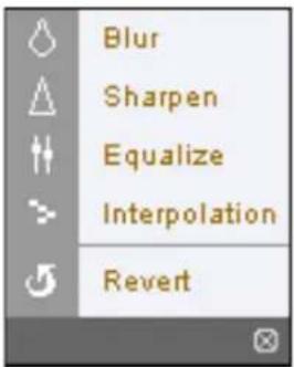 Image processing works only in the pause mode. Image processing works only in the pause mode. | |
| 6 | Playback Control: Click the desired button to play recorded video. The following functions are supported: fast backward, pause, play, fast forward, go to the first image, go to the previous image, go to the next image, and got to the last image. | |
| 7 | Time-Lapse Search: Click to enter the time-lapse search mode which allows you to search for recorded data by time and then play back images found within the time parameters. The Timetable window located at the bottom displays the time information for the image of the date selected on the calendar. If the camera has more than one video segment in the same time range, you can select the video segment you want to search. Clicking a specific time displays the image recorded at that time on the screen.Selecting allows you to display an image from a specific time.  | |
| 8 | Event Search: Click to enter the event search mode which allows you to search for event log entries using specific conditions and play back the images associated with those event entries. | |
| 9 | Setup: Click to set up the image drawing mode and OSD display. You can adjust the display speed by changing the image drawing mode, and select OSD information to be displayed on the screen. | |
| 10 | Save Video: Click to save any video clip of recorded data as a video file. | |
| 11 | Save Image: Click to save the current image in a bitmap or JPEG file format. | |
| 12 | Print: Click to print the current image on a printer connected to your computer. | |
| 13 | Reload: Click to reload the recording data. | |
| 14 | Timetable: Displays recorded data of the camera by time (in hour segments). If the camera's time and date have been reset to a time that is earlier than some recorded video and more than one video segment exists in the same time range, select the video segment you want to search from the SEGMENT menu at the top-right corner on the timetable. | |
| 15 | Screen Popup Menu: Clicking the right mouse button on the screen displays the screen popup menu.Click to enable or disable each function. | |
 | - Change Camera Title: Select to change the camera title.- Enable Audio: Plays audio while playing back recorded video that has recorded audio.- Aspect Ratio: Changes the image aspect ratio.- Anti-Aliasing Screen: Select to enhance image display quality by eliminating stair stepping (aliasing) effects in the enlarged image. | |
 | A camera name change in the Web Search mode does not affect the camera name set up on the camera. Leaving the Camera Title blank causes the camera name set up on the camera to display. | |
Setup Menu Tree (Remote Setup)

flowchart
graph TD
    A["Remote Setup"] --> B["Quick Setup"]
    B --> C["System"]
    B --> D["Network"]
    B --> E["Video"]
    A --> F["System"]
    F --> G["General"]
    F --> H["Date/Time"]
    F --> I["User/Group"]
    A --> J["Network"]
    J --> K["IP Address"]
    J --> L["FEN"]
    J --> M["Port/QoS"]
    J --> N["Bandwidth Control"]
    J --> O["Security"]
    J --> P["IEEE 802.1X"]
    A --> Q["Video"]
    Q --> R["Camera"]
    Q --> S["Streaming"]
    Q --> T["Webcasting"]
    Q --> U["MAT"]
    Q --> V["Privacy Masking"]
    A --> W["Event Action"]
    W --> X["Email"]
    W --> Y["Remote Callback"]
    W --> Z["FTP Upload"]
    W --> AA["Record"]
    A --> AB["Event"]
    AB --> AC["Motion Detection"]
    AB --> AD["Trip zone"]
    AB --> AE["Tampering"]
    AB --> AF["System Event"]
Index
B
Bitrate Control 23
C
Camera Name 9
Compression 23
D
Date/Time 10
DSCP 14
F
FEN Name 13
FEN Server 13
Frame Rate 23
|
IPFiltering 16
M
MAT 25
N
Network Bandwidth Limit 15
0
ONVIF Protocol 9
Q
Quality 23
R
Remote Port 14
Resolution 23
RTSP Port 14
s
SSL 16
T
Time Sync 10
U
Use FEN 13
Use HTTPS 14
User/Group 11
Use UPnP 14
COSTAR
COSTAR VIDEO SYSTEMS
101 Wrangler, Suite 201 Coppell, Texas 75019
Phone: (469) 635-6800
Fax: (469) 635-6822
Toll-free: (888) 694-7827