KM28 - Washing machine Kaden - Free user manual and instructions
Find the device manual for free KM28 Kaden in PDF.

User questions about KM28 Kaden
0 question about this device. Answer the ones you know or ask your own.
Ask a new question about this device
Download the instructions for your Washing machine in PDF format for free! Find your manual KM28 - Kaden and take your electronic device back in hand. On this page are published all the documents necessary for the use of your device. KM28 by Kaden.
USER MANUAL KM28 Kaden
natural_image
Line drawing of a rectangular air conditioner unit (no text or symbols)
natural_image
Line drawing of a modern air conditioner unit with fan and ventilation grille (no text or symbols)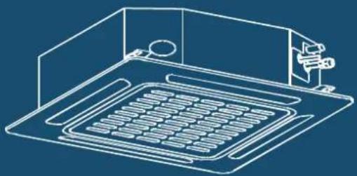
natural_image
Isometric line drawing of a kitchen appliance with a tray and sink (no text or symbols)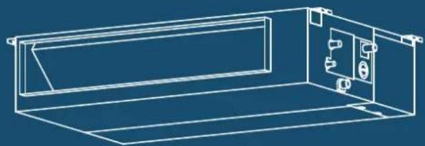
natural_image
Technical line drawing of a rectangular enclosure with internal compartments and mounting fixtures (no text or symbols)Table of contents
Safety precautions 4
KSI Split Air Conditioner 7
- KSI accessories 8
- KSI installation summary -indoor unit 9
- KSI unit parts 11
-
KSI indoor unit installation 12
Installation instructions – indoor unit 12
Prior to installation 12 -
KSI wiring 17
Electrical wiring work 18
Take note of fuse specifications 19
Drain hose must be on bottom 20
Do not intertwine signal cable with other wires 20
Do not wrap ends of piping 20
- KSI electrical checks 21
Wi-Fi operation setup 21
- KSI test run 22
Before test run 22
Test run instructions 22
- KSI error codes 23
KMD Multi Ducted Air Conditioner 25
- KMD accessories 26
- KMD installation summary 27
- KMD unit parts 28
-
KMD indoor unit installation 29
Installation instructions – indoor unit 29 -
KMD wiring 36
Indoor unit wiring 38 -
KMD test run 39
Before test run 39
Test run instructions 39 -
KMD error codes 40
KMC Multi Cassette Air Conditioner 41
- KMC accessories 42
- KMC installation summary 43
-
KMC unit parts 44
-
KMC indoor unit installation 45
Installation instructions – indoor unit 45
Note for new home installation 48
Note on purchasing drain pipes 48
Note on drainpipe installation 49
- KMC wiring 50
Indoor unit wiring 52
-
KMC panel installation 53
-
KMC test run 54
Before test run 54
Test run instructions 54
- KMC error codes 55
KM Multi Outdoor Unit 57
-
KM accessories 58
-
KM installation summary 59
-
KM specifications 60
-
KM unit installation 61
Installation instructions – outdoor unit 61
Special considerations for extreme weather 61
Notes on drilling hole in wall 63
When selecting a KS09 indoor unit 63
- KM refrigerant piping connection 64
Note on pipe length 64
Connection instructions – refrigerant piping 66
Note on minimum bend radius 68
- KM wiring 69
Note on isolator 69
Circuit breaker recommendations 70
Outdoor unit wiring 71
Harmonic declaration 71
Wiring figure 72
- KM leak testing and evacuation 78
Leak, pressure test and evacuation 78
Preparations and precautions 79
Before performing evacuation 79
Opening outdoor unit valves 79
Note on adding refrigerant 80
Safety and leakage check 81
- KM test run 82
Before test run 82
Test run instructions 82
- KM automatic wiring/piping connection 83
Automatic wiring/piping connection function 83
How to activate this function 83
Important note
Read this manual carefully before installing
or operating your new air conditioning unit.
Make sure to save this manual for future reference.
Safety precautions
Read safety precautions before operation and installation
Incorrect installation due to ignoring instructions can cause serious damage or injury.
The seriousness of potential damage or injuries is classified as either a WARNING or CAUTION.

This symbol is a WARNING, and indicates that ignoring instructions may cause death or serious injury.

This symbol is a CAUTION, and indicates that ignoring instructions may cause moderate injury to your person, or damage to your unit or other property.
This symbol indicates that you must never perform the action indicated.

WARNING
Do not share the electrical outlet with other appliances. Improper or insufficient power supply can cause fire or electrical shock.
When connecting refrigerant piping, do not let substances or gases other than the specified refrigerant enter the unit. The presence of other gases or substances will lower the unit's capacity, and can cause abnormally high pressure in the refrigeration cycle. This can cause explosion and injury.
Do not allow children to play with the air conditioner. Children must be supervised around the unit at all times.
- Installation must be performed by a licensed installer. Incorrect installation can cause water leakage, electrical shock, or fire.
- Installation must be performed according to the installation instructions. Improper installation can cause water leakage, electrical shock, or fire.
- Contact an authorised service technician for repair or maintenance of this unit.
- Only use the included accessories, parts, and specified parts for installation. Using non-standard parts can cause water leakage, electrical shock, fire, and can cause the unit to fail.
-
Install the unit in a firm location that can support the unit's weight. If the chosen location cannot support the unit's weight, or the installation is not done properly, the unit may drop and cause serious injury and damage.
-
Only fully qualified licensed personnel should install service or carry out maintenance to this air conditioning unit. All electrical work is to follow local and national wiring standards and the Installation Manual.
- You must use an independent circuit and single outlet to supply power. Do not connect other appliances to the same outlet. Insufficient electrical capacity or defects in electrical work can cause electrical shock or fire.
- For all electrical work, use the specified cables. Connect cables tightly, and clamp them securely to prevent external forces from damaging the terminal. Improper electrical connections can overheat and cause fire, and may also cause shock.
- All wiring must be properly arranged to ensure that the control board cover can close properly. If the control board cover is not closed properly, it can lead to corrosion and cause the connection points on the terminal to heat up, catch fire, or cause electrical shock.
- In certain functional environments, such as kitchens, server rooms, etc., the use of specially designed air-conditioning units is highly recommended.
- This appliance can be used by children aged from 8 years and above and persons with reduced physical, sensory or mental capabilities or lack of experience and knowledge if they have been given supervision or instruction concerning use of the appliance in a safe way and understand the hazards involved. Children must not play with the appliance. Cleaning and user maintenance must not be made by children without supervision.

AUTION
Do not install the unit in a location that may be exposed to combustible gas leaks. If combustible gas accumulates around the unit, it may cause fire.
Do not operate your air conditioner in a wet room such as a bathroom or laundry room. Too much exposure to water can cause electrical components to short circuit.
-
The product must be properly grounded at the time of installation, or electrical shock may occur.
-
Install drainage piping according to the instructions in this manual. Improper drainage may cause water damage to your home and property.
Note about fluorinated gases
- This air-conditioning unit contains fluorinated gases. For specific information on the type of gas and the amount, please refer to the relevant label on the unit itself.
- Installation, decommissioning, service, maintenance and repair of this unit must be performed by a licensed technician.
- Product decommissioning and recycling must be performed by a licensed technician.
- If the system has a leak-detection system installed, it must be checked for leaks at least every 12 months.
- When the unit is checked for leaks, proper record-keeping of all checks is strongly recommended.
- Only ARC (Australian Refrigeration Council) licence holders can install and commission this air conditioner. This air conditioner must be installed to meet the requirements of the current version of AS/NZS 5149. It is illegal to vent some types of refrigerant to the atmosphere.

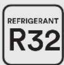
REFRIGERANT
This appliance uses R32 (difluoromethane) refrigerant, which is a flammable gas class 2.2 according to AS/NZS 5149 and must be handled by a refrigeration mechanic with appropriate Australian refrigerant handling licence.
- WARNING risk of fire/flammable material. If the refrigerant is leaked, together with an external ignition source, there is possibility of ignition.
- Read all the OPERATING INSTRUCTIONS carefully before operation.
- Service personnel are required to carefully read the OPERATING INSTRUCTIONS and INSTALLATION MANUAL before operation.
• Further information is available in the OPERATING INSTRUCTIONS, INSTALLATION MANUAL and the like.
Certain levels of refrigerant require minimum room sizes. Please ensure that these minimum room sizes are adhered to for standard installations (up to 10m pipe length). If larger refrigerant charges than standard are used then please consult AS/NZS 60335.2.40 to determine the safe minimum floor area for the installation.
Make sure that the area has been made safe by having suitable ventilation and is free from ignition sources before charging or recovering the charge of R32.

WARNINGS FOR PRODUCT INSTALLATION
- Installation must be performed by an authorised technician. Defective installation can cause water leakage, electrical shock, or fire.
- Installation must be performed according to the installation instructions. Improper installation can cause water leakage, electrical shock, or fire.
- Contact an authorised service technician for repair or maintenance of this unit. This appliance shall be installed in accordance with national wiring regulations.
- Only use the included accessories, parts, and specified parts for installation. Using non-standard parts can cause water leakage, electrical shock, fire, and can cause the unit to fail.
- Install the unit in a firm location that can support the unit's weight. If the chosen location cannot support the unit's weight, or the installation is not done properly, the unit may drop and cause serious injury and damage.
- Install drainage piping according to the instructions in this manual. Improper drainage may cause water damage to your home and property.
- For units that have an auxiliary electric heater, do not install the unit within 1 metre (3 feet) of any combustible materials.
- Do not install the unit in a location that may be exposed to combustible gas leaks. If combustible gas accumulates around the unit, it may cause fire.
- Do not turn on the power until all work has been completed.
- When moving or relocating the air conditioner, consult authorised service technicians for disconnection and re-installation of the unit.
- How to install the appliance to its support, please read the information for details in "indoor unit installation" and "outdoor unit installation" sections.
NOTE ABOUT FLUORINATED GASES
- This air-conditioning unit contains fluorinated gases. For specific information on the type of gas and the amount, please refer to the relevant label on the unit itself.
- Installation, decommissioning, service, maintenance and repair of this unit must be performed by a licensed technician.
- Product decommissioning and recycling must be performed by a licensed technician.
- If the system has a leak-detection system installed, it must be checked for leaks at least every 12 months.
- When the unit is checked for leaks, proper record-keeping of all checks is strongly recommended.
- Only ARC (Australian Refrigeration Council) license holders can install and commission this air conditioner. This air conditioner must be installed to meet the requirements of the current version of AS/NZS 5149. It is illegal to vent some types of refrigerant to the atmosphere.
R32 WALL MOUNTED AIR CONDITIONER
KSI Split Air Conditioner
KSI06 | KSI09 | KSI12 | KSI18 | KSI24 | KSI28

natural_image
Line drawing of a rectangular air conditioner unit (no text or symbols)Important note
This appliance must be installed in accordance with:
Manufacturer's Installation Instructions
Current AS/NZS 3000, AS/NZS 5149
Local Regulations and Municipal Building Codes including local OH&S requirements
This appliance must be installed, maintained, and removed only by an Authorised Person.
For continued safety of this appliance, it must be installed and maintained in accordance with the manufacturer's Instructions.


1. KSI accessories
The air conditioning system comes with the following accessories. Use all of the installation parts and accessories to install the air conditioner. Improper installation may result in water leakage, electrical shock and fire, or cause the equipment to fail.
| Name of Accessories Qty (pc) | Shape | |
| Mounting plate 1 | [HXY] | |
| Clip anchor 5 | [7TH0] | |
| Mounting plate fixing screw ST3.9 x 25 5 | [7386] | |
| Remote controller 1 |  | |
| Fixing screw for remote controller holder ST2.9 x 10 | 2 | [X263] |
| Remote controller holder 1 | 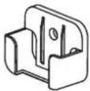 | |
| Dry battery AAA.LR03 2 | 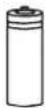 | |
| Drain seal 1 | 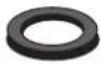 | |
| Drain joint 1 | [WCD0] | |
| Owner's and Controller Manual 1 |  | |
| Installation Manual 1 | [XTTW] |
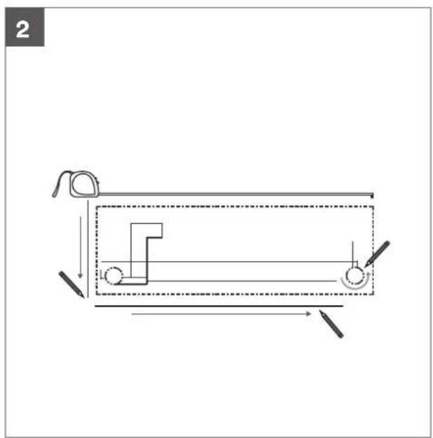
2. KSI installation summary – indoor unit
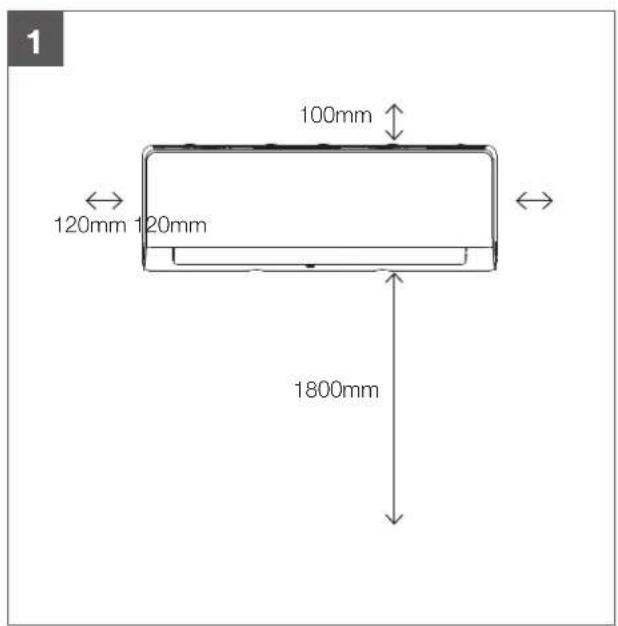
text_image
1 100mm 120mm 120mm 1800mmSelect installation location Determine wall hole position
natural_image
Pure mechanical diagram showing a lever mechanism with no text or symbols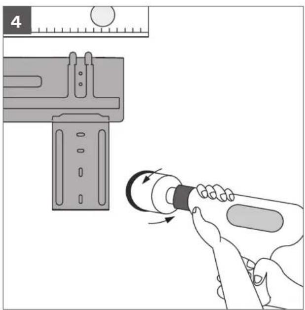
natural_image
Illustration of a hand using a tool to adjust a component, with no visible text or symbols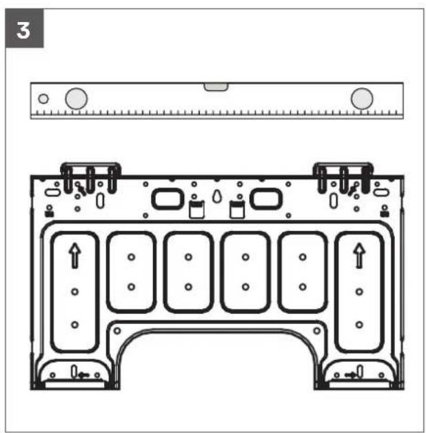
text_image
3Attach mounting plate Drill wall hole
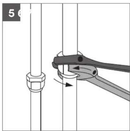
natural_image
Mechanical diagram showing a pipe fitting with a clamping tool (no text or symbols)
text_image
L N S
natural_image
Illustration of two hands holding a small object near a textured surface (no text or symbols)Connect piping Connect wiring Prepare drain hose
natural_image
Diagram of a cable assembly with exposed and hidden wires, no text or symbols presentWrap piping and cable
natural_image
Illustration of two hands holding a horizontal bar with upward arrows, no text or symbols presentMount indoor unit
3. KSI unit parts
Wall-mounted air conditioner
Indoor unit
1 Panel frame
2 Rear air intake grille
3 Front panel
4 Air purifying filter and air filter (behind)
5 Horizontal louvre
6 LCD display window
7 Vertical louvre
8 Manual control button (behind)
9 Remote controller holder

AUTION
- Use a stud finder to locate studs to prevent unnecessary damage to the wall.
- A minimum pipe run of 3000mm is required to minimise vibration and excessive noise.
- A, B, and C directions should be free from intrusion or obstruction.
- This illustration is for explanation purposes only. The actual style of indoor and outdoor unit may be slightly different.
• Copper refrigerant lines must be insulated independently.

text_image
1 2 3 4 5 6 7 8 9 One-five One-four One-three One-twin One-twin4. KSI indoor unit installation

natural_image
Line drawing of a rectangular air conditioner unit (no text or symbols)Installation instructions – indoor unit
Prior to installation
Before installing the indoor unit, refer to the label on the product box to make sure that the model number of the indoor unit matches the model number of the outdoor unit.
Step 1: Select installation location
Before installing the indoor unit, you must choose an appropriate location. The following are standards that will help you choose an appropriate location for the unit.
Proper installation locations meet the following standards:
√ Good air circulation
√ Convenient drainage
√ Noise from the unit will not disturb other people
√ Firm and solid — the location will not vibrate
√ Strong enough to support the weight of the unit
√ A location at least one meter from all other electrical devices (e.g. TV, radio, computer)
DO NOT install unit in the following locations:
× Near an obstacle that will block air inlets and outlets.
✗ Near any obstacle that might block air circulation
× Near the doorway
✗ In a location subject to direct sunlight
Note about wall hole
While choosing a location, be aware that you should leave ample room for a wall hole (see drill wall hole for connective piping step) for the signal and power cable and refrigerant piping that connect the indoor and outdoor units. The default position for all piping is the right side of the indoor unit (while facing the unit).
However, the unit can accommodate piping to both the left and right.
Refer to the following diagram to ensure proper distance from walls and ceiling:

text_image
100mm or more 120mm or more 120mm or more 1800mm or moreStep 2: Attach mounting plate to wall
The mounting plate is the device on which you will mount the indoor unit.
- Remove the screw that attaches the mounting plate to the back of the indoor unit.
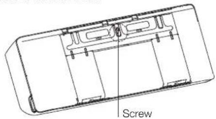
text_image
Screw- Secure the mounting plate to the wall with the screws provided. Make sure that mounting plate is flat against the wall.
Note for concrete or brick walls
If the wall is made of brick, concrete, or similar material, drill 5mm diameter holes in the wall and insert the sleeve anchors provided. Then secure the mounting plate to the wall by tightening the screws directly into the clip anchors.
Step 3: Drill wall hole for connective piping
You must drill a hole in the wall for refrigerant piping, the drainage pipe, and the signal cable that will connect the indoor and outdoor units.
- Determine the location of the wall hole based on the position of the mounting plate. Refer to mounting plate dimensions on the next page to help you determine the optimal position. The wall hole should have a 65mm diameter at least, and at a slightly lower angle to facilitate drainage.
- Using a 65mm or 90mm (depending on models) core drill, drill a hole in the wall. Make sure that the hole is drilled at a slight downward angle, so that the outdoor end of the hole is lower than the indoor end by about 5mm to 7mm. This will ensure proper water drainage.
- Place the protective wall cuff in the hole. This protects the edges of the hole and will help seal it when you finish the installation process.
CAUTION
When drilling the wall hole, make sure to avoid wires, plumbing, and other sensitive components.
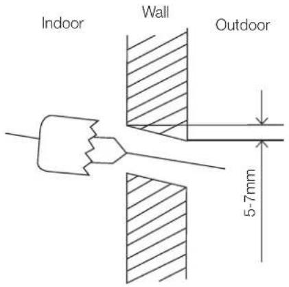
text_image
Indoor Wall Outdoor 5-7mmMounting plate dimensions
Different models have different mounting plates. In order to ensure that you have ample room to mount the indoor unit, the diagrams to the right show different types of mounting plates along with the following dimensions:
- Width of mounting plate
• Height of mounting plate - Width of indoor unit relative to plate
• Height of indoor unit relative to plate - Recommended position of wall hole (both to the left and right of mounting plate)
- Relative distances between screw holes
Model Width of indoor unit
relative to plate
Model A - KSI06/09/12 453.2mm
Model E - KSI18/24/28 645±1mm
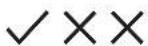
Correct orientation of mounting plate
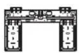
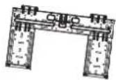

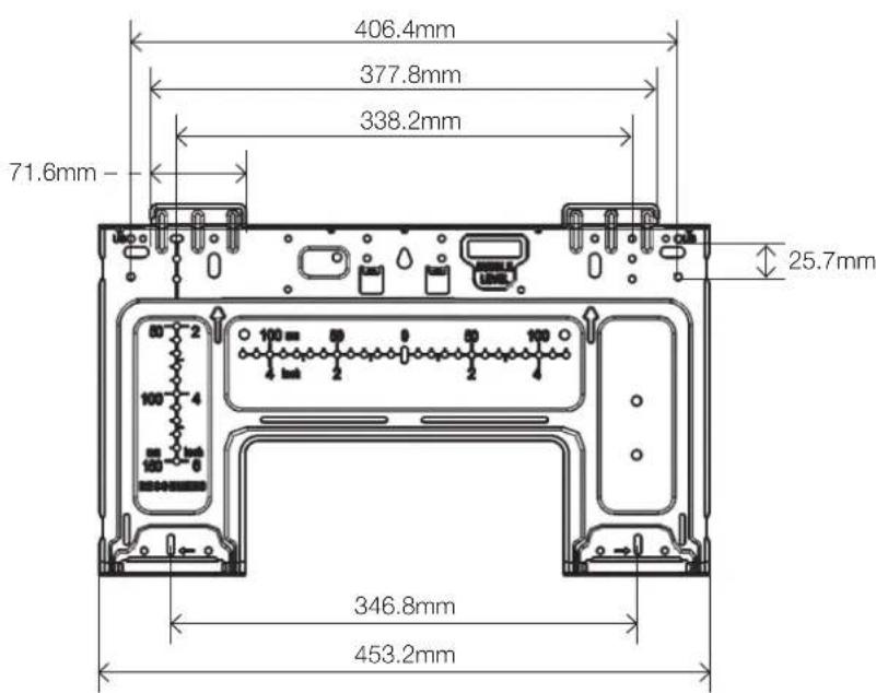
text_image
406.4mm 377.8mm 338.2mm 71.6mm - 25.7mm 346.8mm 453.2mmModel A - KSI06 / KSI09 / KSI12

text_image
645±1mm 531±0.5mm 65mm 65mm 65mm 65mm 65mm 54mm 285±0.5mm 304±0.5mm 429.5±0.5mmModel E - KSI18 / KSI24 / KSI28
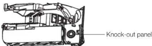
Step 4: Prepare refrigerant piping
The refrigerant piping is inside an insulating sleeve attached to the back of the unit. You must prepare the piping before passing it through the hole in the wall.
- Based on the position of the wall hole relative to the mounting plate, choose the side from which the piping will exit the unit.
- If the wall hole is behind the unit, keep the knock-out panel in place. If the wall hole is to the side of the indoor unit, remove the plastic knock-out panel from that side of the unit. This will create a slot through which your piping can exit the unit. Use needle nose pliers if the plastic panel is too difficult to remove by hand.

Knock-out panel
- Connect drain hose step. If there is no embedded piping, connect the indoor unit's refrigerant piping to the connective piping that will join the indoor and outdoor units. Refer to the Refrigerant piping connection section of this manual for detailed instructions.
NOTE ON PIPING ANGLE: Refrigerant piping can exit the indoor unit from four different angles: left-hand side, right-hand side, left rear, right rear.
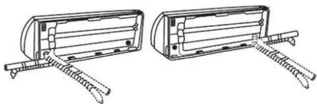
natural_image
Technical line drawing of two mechanical components with spring-loaded arms (no text or symbols)
CAUTION
Be extremely careful not to dent or damage the piping while bending them away from the unit. Any dents in the piping will affect the unit's performance.
Step 5: Connect drain hose
By default, the drain hose is attached to the left-hand side of unit (when you're facing the back of the unit). However, it can also be attached to the right-hand side. To ensure proper drainage, attach the drain hose on the same side that your refrigerant piping exits the unit. Attach drain hose extension (purchased separately) to the end of drain hose.
- Wrap the connection point firmly with teflon tape to ensure a good seal and to prevent leaks.
- For the portion of the drain hose that will remain indoors, wrap it with foam pipe insulation to prevent condensation.
- Remove the air filter and pour a small amount of water into the drain pan to make sure that water flows from the unit smoothly.

NOTE ON DRAIN HOSE PLACEMENT
Make sure to arrange the drain hose according to the following figures.

natural_image
Simple line drawing of a mechanical bracket and vertical wall, with a checkmark indicating a detail (no text or symbols present)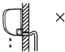
natural_image
Simple line drawing of a hook and rod inserted into a vertical wall, with a cross symbol indicating a defect or mark (no text or labels)CORRECT
Make sure there are no kinks or dent in drain hose to ensure proper drainage.
NOT CORRECT
Kinks in the drain hose will create water traps.
natural_image
Simple line drawing of a mechanical or electrical component with no text or symbols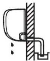
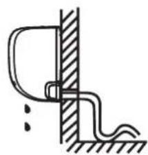
NOT CORRECT
Kinks in the drain hose will create water traps.
NOT CORRECT
Do not place the end of the drain hose in water or in containers that collect water. This will prevent proper drainage.
Plug the unused drain hole
To prevent unwanted leaks you must plug the unused drain hole with the rubber plug provided.
5. KSI wiring
! BEFORE PERFORMING ANY ELECTRICAL WORK, READ THESE REQUIREMENTS
- All wiring must comply with local and national electrical codes, and must be installed by a licensed electrician.
- All electrical connections must be made according to the electrical connection diagram located on the panels of the indoor and outdoor units.
- If there is a serious safety issue with the power supply, stop work immediately. Explain your reasoning to the client, and refuse to install the unit until the safety issue is properly resolved.
- Power voltage should be within 90-100% of rated voltage. Insufficient power supply can cause malfunction, electrical shock, or fire.
- If connecting power to fixed wiring, install a surge protector and main power switch with a capacity of 1.5 times the maximum current of the unit.
- If connecting power to fixed wiring, a switch or circuit breaker that disconnects all poles and has a contact separation of at least 3mm must be incorporated in the fixed wiring. The qualified technician must use an approved circuit breaker or switch.
- Only connect the unit to an individual branch circuit outlet. Do not connect another appliance to that outlet.
- Make sure to properly ground the air conditioner.
- Every wire must be firmly connected. Loose wiring can cause the terminal to overheat, resulting in product malfunction and possible fire.
- Do not let wires touch or rest against refrigerant tubing, the compressor, or any moving parts within the unit.

WARNING
Before performing any electrical or wiring work, turn off the main power to the system.
Choose the right cable size
The size of the power supply cable, signal cable, fuse, and switch needed is determined by the maximum current of the unit. The maximum current is indicated on the nameplate located on the side panel of the unit. Refer to this name plate to choose the right cable, fuse, or switch.
Electrical requirement
The indoor unit is powered by the outdoor unit. Do not power indoor unit from separate power source.
| Cable Conductor size (mm2) | Type Remarks | ||
| Interconnect power cable | 1.5 Type | 60245IEC 57 | 3 cable + Earth(Ground)1 ∅ 230 V |
Cable length: Limit voltage drop to less than 2%. Increase cable gauge if voltage drop is 2% or more.
If the interconnect cable exceeds 30000mm in length 2.5mm thick cable should be used.
The cable specifications are based on the assumption that a metal or plastic conduit is used with no more than three cables contained in a conduit and a voltage drop of 2%.

WARNING
Standard for electrical wiring and equipment differs in each country or region. Before you start electrical work, confirm related regulations, codes or standards.
Electrical wiring work
- Before installation, make sure that the power source complies with the air-conditioner's power specification
- Carry out electrical wiring work according to following guidelines
Preparing cable
- Selecting cable. Select the connecting cable in accordance with the specifications mentioned below. 4-core* 1.5mm^2 conformed with 60245 IEC57. *1 Earth wire is included (yellow/green).
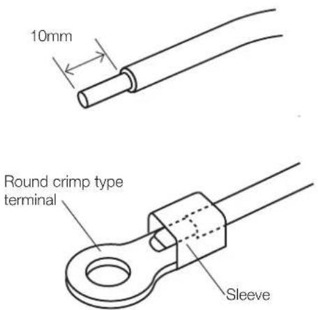
- Arrange each wire length as shown below. Make sure that each wire is stripped 10mm from the end.
Connecting cable
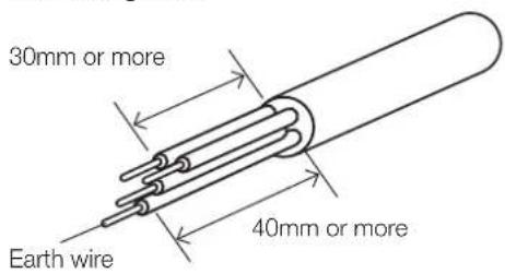
text_image
30mm or more Earth wire 40mm or moreWire end

text_image
10mm- Attach round crimp-type terminal to each wire as shown below. Select the size of round crimp-type terminal after considering the specifications of terminal block and wire diameter.

text_image
10mm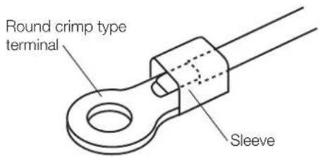
text_image
Round crimp type terminal SleeveTake note of fuse specifications
The air conditioner's circuit board (PCB) is designed with a fuse to provide overcurrent protection. The specifications of the fuse are printed on the circuit board, such as: T3.15A/250VAC, T5A/250VAC, etc.
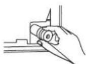
- Open front panel of the indoor unit.
- Using a screwdriver, open the wire box cover on the right side of the unit. This will reveal the terminal block.
Front view
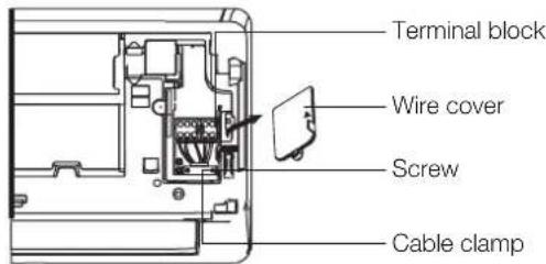
text_image
Terminal block Wire cover Screw Cable clampBack view (for some units only)
text_image
Knock-out panelNOTE:
- For the units with conduit tube to connect the cable, remove the big plastic knock-out panel to create a slot through which the conduit tube can be installed.
- For the units with five-core cable, remove the middle small plastic knock-out panel to create a slot through which the cable can exit.
-
Use needle nose pliers if the plastic panel is too difficult to remove by hand.
-
Unscrew the cable clamp below the terminal block and place it to the side.
- Facing the back of the unit, remove the plastic panel on the bottom left-hand side.
- Feed the signal wire through this slot, from the back of the unit to the front.
- Facing the front of the unit, connect the wire according to the indoor unit's wiring diagram, connect the u-lug and firmly screw each wire to its corresponding terminal.

WARNING
DO NOT MIX UP LIVE AND NULL WIRES
This is dangerous, and can cause the air conditioning unit to malfunction.
- Unscrew the cable clamp below the terminal block and place it to the side.
- Facing the back of the unit, remove the plastic panel on the bottom left-hand side.
- Feed the signal wire through this slot, from the back of the unit to the front.
- Facing the front of the unit, match the wire colours with the labels on the terminal block, connect the u-lug and firmly screw each wire to its corresponding terminal.
- After checking to make sure every connection is secure, use the cable clamp to fasten the signal cable to the unit. Screw the cable clamp down tightly.
- Replace the wire cover on the front of the unit, and the plastic panel on the back.

OTE ABOUT WIRING
The wiring connection process may differ slightly between units.
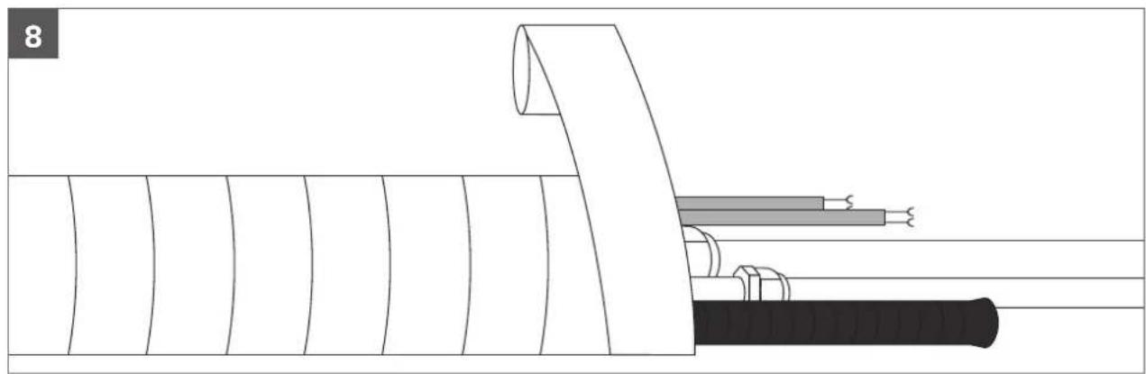
Step 6: Wrap piping and cables
Before passing the piping, drain hose, and the signal cable through the wall hole, you must bundle them together to save space, protect them, and insulate them.
- Bundle the drain hose, refrigerant pipes, and signal cable.
Indoor unit

text_image
Space behind unit Refrigerant piping Insulation tape Drain hoseSignal wireDrain hose must be on bottom
Make sure that the drain hose is at the bottom of the bundle. Putting the drain hose at the top of the bundle can cause the drain pan to overflow, which can lead to fire or water damage.
Do not intertwine signal cable with other wires
While bundling these items together, do not intertwine or cross the signal cable with any other wiring.
- Using adhesive vinyl tape, attach the drain hose to the underside of the refrigerant pipes.
- Using insulation tape, wrap the signal wire, refrigerant pipes, and drain hose tightly together.
Do not wrap ends of piping
When wrapping the bundle, keep the ends of the piping unwrapped. You need to access them to test for leaks during of the installation process (refer to Electrical checks and leak checks section of this manual).
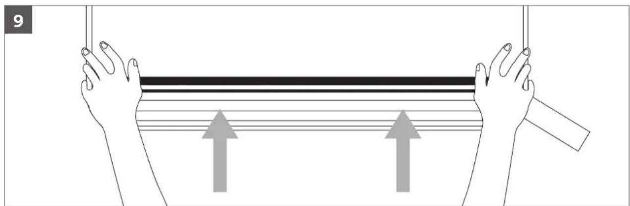
Step 7: Mount indoor unit
If you installed new connective piping to the outdoor unit, do the following:
- If you have already passed the refrigerant piping through the hole in the wall, proceed to Step 4.
- Otherwise, double-check that the ends of the refrigerant pipes are sealed to prevent dirt or foreign materials from entering the pipes.
- Slowly pass the wrapped bundle of refrigerant pipes, drain hose, and signal wire through the hole in the wall.
- Hook the top of the indoor unit on the upper hook of the mounting plate.
- Check that unit is hooked firmly on mounting by applying slight pressure to the left and right-hand sides of the unit. The unit should not jiggle or shift.
- Using even pressure, push down on the bottom half of the unit. Keep pushing down until the unit snaps onto the hooks along the bottom of the mounting plate.
- Again, check that the unit is firmly mounted by applying slight pressure to the left and the right-hand sides of the unit.
If refrigerant piping is already roughed into the wall
New refrigerant piping must be used as older piping may not meet the safe working pressure requirements of R32.
Residual mineral oil in existing pipe work is not compatible with R32 and POE oil.
- Hook the top of the indoor unit on the upper hook of the mounting plate.
- Use a bracket or wedge to prop up the unit, giving you enough room to connect the refrigerant piping, signal cable, and drain hose.
- Connect drain hose and refrigerant piping (refer to refrigerant piping connection section of this manual for instructions).
- Keep pipe connection point exposed to perform the leak test (refer to Electrical checks and leak checks section of this manual).
- After the leak test, wrap the connection point with insulation tape.
- Remove the bracket or wedge that is propping up the unit.
- Using even pressure, push down on the bottom half of the unit. Keep pushing down until the unit snaps onto the hooks along the bottom of the mounting plate.
6. KSI electrical checks
Electrical safety checks
After installation, confirm that all electrical wiring is installed in accordance with local and national requirements, and according to the Installation Manual.
Before test run
Check grounding work
Measure grounding resistance by visual detection and with grounding resistance tester. Grounding resistance must be less than 4 .
During test run
Check for electrical leakage
During the test run, use an electroprobe and multimeter to perform a comprehensive electrical leakage test.
If electrical leakage is detected, turn off the unit immediately and call a licensed electrician to find and resolve the cause of the leakage.

WARNING – RISK OF ELECTRIC SHOCK
All wiring must comply with local and national electrical codes, and must be installed by a licensed electrician.
Wi-Fi operation setup
For instructions on setting up Wi-Fi connectivity for your Kaden air conditioner, please scan the QR code below, or visit kadenair.com.au

text_image
QR code image containing encoded data, no visible human-readable text7. KSI test run
Before test run
Only perform test run after you have completed the following steps:
- Refrigerant leak checks – check all flare nut connections and confirm that the system is not leaking
- Electrical safety checks – confirm that the unit's electrical system is safe and operating properly
- Confirm that gas and liquid (high and low pressure) valves are fully open
Test run instructions
You should perform the test run for at least 30 minutes.
- Connect power to the unit.
- Press the ON/OFF button on the remote controller to turn it on.
- Press the MODE button to scroll through the following functions, one at a time:
• COOL – Select lowest possible temperature
- HEAT – Select highest possible temperature
- Let each function run for 5 minutes, and perform the following checks:
List of checks to perform Pass/fail
| No electrical leakage | ||
| Unit is properly grounded | ||
| All electrical terminals properly covered | ||
| Indoor and outdoor units are solidly installed | ||
| All pipe connection points do not leak | Outdoor (2): | Indoor (2): |
| Water drains properly from drain hose | ||
| All piping is properly insulated | ||
| Unit performs COOL function properly | ||
| Unit performs HEAT function properly | ||
| Indoor unit louvres rotate properly | ||
| Indoor unit responds to remote controller |
Double-check pipe connections
During operation, the pressure of the refrigerant circuit will increase. This may reveal leaks that were not present during your initial leak check. Take time during the test run to double-check that all refrigerant pipe connection points do not have leaks. Refer to gas leak check section for instructions.
- After the test run is successfully completed, and you confirm that all checks points in list of checks to perform have PASSED, do the following:
a. Using remote control, return unit to normal operating temperature.
b. Using insulation tape, wrap the indoor refrigerant pipe connections that you left uncovered during the indoor unit installation process.
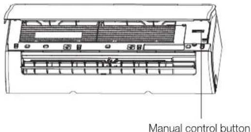
If ambient temperature is below 17^ C ( 63^ F)
You can't use the remote controller to turn on the COOL function when the ambient temperature is below 17°C. In this instance, you can use the MANUAL CONTROL button to test the COOL function.
- The MANUAL CONTROL button is located on the right-hand side panel of the unit.
- Press the button 2 times to select the COOL function.
- Perform test run as normal.
text_image
Manual control button8. KSI error codes
Error display (indoor unit)
When the indoor unit encounters a recognized error on different models.
- The running LED with flash in a corresponding series, the timer LED may turn on or begin flashing;
- An error code will be displayed;
- Both 1 and 2.
These error codes are described in the following tables:
| Running lamp | Timer lamp | Display Information Solution | ||
| 1 time | × | EH 00/EH 0A Indoor unit EEPROM parameter error TS01-IDU | ||
| 2 times | × | EL 01 Indoor/outdoor unit communication error TS02-S-INV | ||
| 3 times | × | EH 02 Zero-crossing signal detection error TS03 | ||
| 4 times | × | EH 03 The indoor fan speed is operating outside of the normal range TS04-S-IDU | ||
| 5 times | × | EC 51 Outdoor unit EEPROM parameter error TS01-ODU | ||
| 5 times | × | EC 52 Condenser coil temperature sensor T3 is in open circuit or has short circuited | TS05-ODU | |
| 5 times | × | EC 53 Outdoor room temperature sensor T4 is in open circuit or has short circuited | TS05-ODU | |
| 5 times | × | EC 54 Compressor discharge temperature sensor TP is in open circuit or has short circuited | TS05-ODU | |
| 5 times | × | EC 56 Evaporator coil outlet temperature sensor T2B is in open circuit or has short circuited (for free-match indoor units) | TS05-ODU | |
| 6 times | × | EH 60 Indoor room temperature sensor T1 is in open circuit or has short circuited | TS05-IDU | |
| 6 times | × | EH 61 Evaporator coil middle temperature sensor T2 is in open circuit or has short circuited | TS05-IDU | |
| 12 times | × | EC 07 The outdoor fan speed is operating outside of the normal range TS04-ODU | ||
| 9 times | × | EH 0b Indoor PCB/Display board communication error TS07 | ||
| 8 times | × | EL 0C Refrigerant leakage detection | TS06-INV | |
| 7 times | △ | PC 00 | IPM malfunction or IGBT over-strong current protection | TS09-S |
| 2 times | △ | PC 01 Over voltage or over low voltage protection | TS10-S | |
| 3 times | △ | PC 02 Top temperature protection of compressor or High temperature protection of IPM module or High pressure protection | TS11-S-INV | |
| 5 times | △ | PC 04 Inverter compressor drive error | TS12-S | |
| 1 time | △ | PC 08 Current overload protection | TS08-S | |
| 6 times | △ | PC 40 Communication error between outdoor main chip and compressor driven chip | TS33 | |
| 7 times | △ | PC 03 Low pressure protection | TS13-INV | |
| 1 time | ○ | Indoor units mode conflict (match with multi outdoor unit) | TS14 | |
O on
× off
△ flash
For other errors:
The display board may show a garbled code or a code undefined by the service manual. Ensure that this code is not a temperature reading.
Troubleshooting:
Test the unit using the remote control. If the unit does not respond to the remote, the indoor PCB requires replacement. If the unit responds, the display board requires replacement.
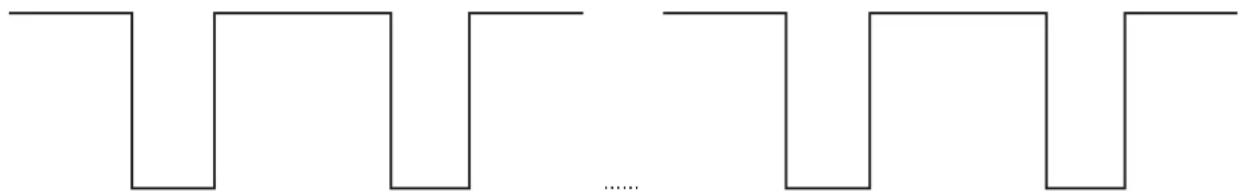
88 flash frequency:
1s 0.4s 1.2s 0.4s 1s 0.4s 1.2s 0.4s
natural_image
Pure electrical circuit lines without any symbolsThe design and specifications are subject to change without prior notice for product improvement. Consult with the sales agency or manufacturer for details. Any updates to the manual will be uploaded to the service website. Please check for the latest version.
MULTI DUCTED INDOOR AIR CONDITIONER
KMD Multi Ducted Air Conditioner
KMD09 | KDM12 | KMD18 | KMD24
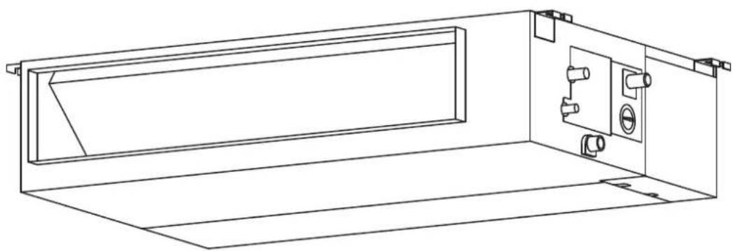
natural_image
Technical line drawing of a cabinet or enclosure with internal components (no text or symbols)1. KMD accessories
The air conditioning system comes with the following accessories. Use all of the installation parts and accessories to install the air conditioner. Improper installation may result in water leakage, electrical shock and fire, or cause the equipment to fail. The items not included with the air conditioner must be purchased separately.
| Name of accessories Qty (pc) Shape Name of accessories Qty (pc) Shape | |||||
| Owner's and Controller Manual | 1 |  | Seal ring 1 |  | |
| Installation Manual 1 |  | Connecting wire for display (2000mm) | 1 |  | |
| Soundproof/insulation sheath | 2 |  | Magnetic ring S1 & S2 1 |  | |
| Copper nut 2 Magnetic ring |  | Varies by model |  | ||
| Display panel 1 |  | Cord protection rubber ring | 1 |  | |
| Drain joint 1 |  | ||||
Optional accessories
There are two types of remote controls: wired and wireless. Select a remote controller based on customer preferences and requirements and install in an appropriate place. Refer to catalogues and technical literature for guidance on selecting a suitable remote controller.
Important note
This appliance must be installed in accordance with:
Manufacturer's Installation Instructions
Current AS/NZS 3000, AS/NZS 5149
Local Regulations and Municipal Building Codes including local OH&S requirements
This appliance must be installed, maintained, and removed only by an Authorised Person.
For continued safety of this appliance, it must be installed and maintained in accordance with the manufacturer's Instructions.

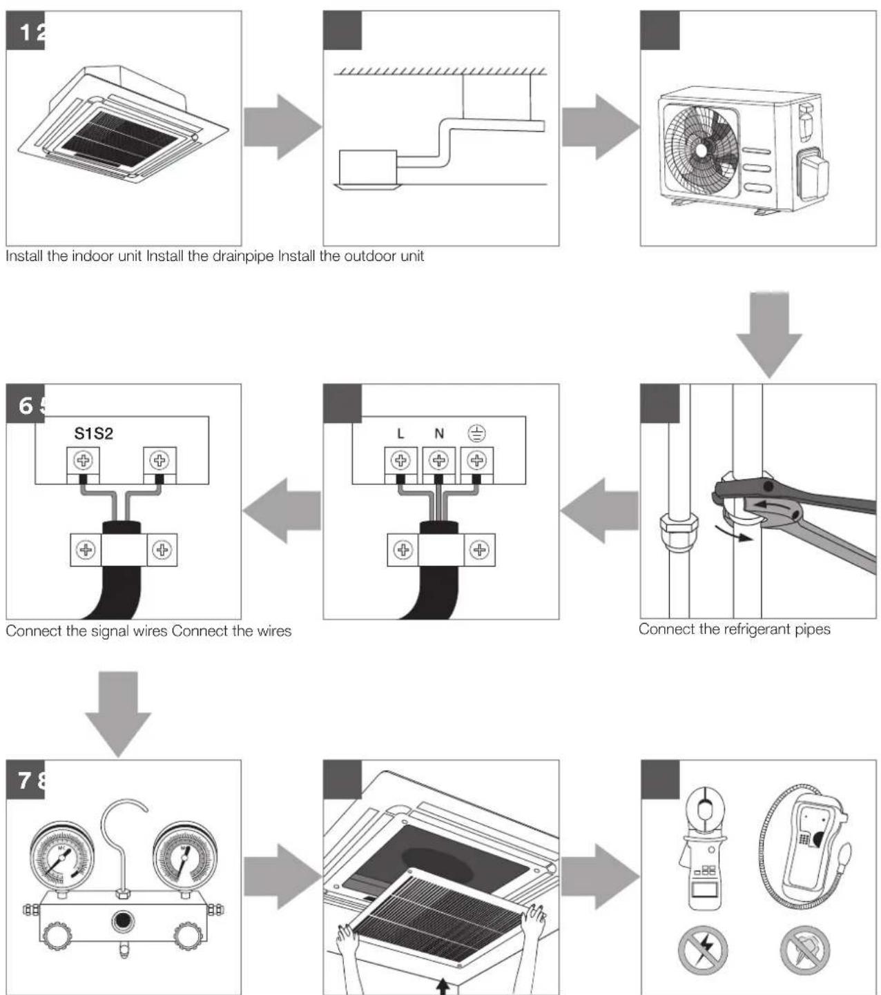
2. KMD installation summary

Install the indoor unit Install the drainpipe Install the outdoor unit
Connect the signal wires Connect the wires Connect the refrigerant pipes
Pressure test and evacuation
Perform a test run
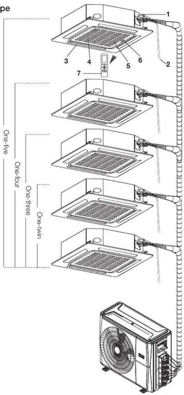
3. KMD unit parts
NOTE: The installation must be performed in accordance with the requirement of local and national standards. The installation may be slightly different in different areas.
Duct/ceiling type
1 Air out
2 Air in
3 Air filter
4 Electric control box
5 Wire control

text_image
One-five One-four One-three One-twoNote on illustrations
Illustrations in this manual are for explanatory purposes. The actual shape of your indoor unit may be slightly different.
4. KMD indoor unit installation
Installation instructions – indoor unit
NOTE: Panel installation should be performed after piping and wiring have been completed.
Step 1: Select installation location
Before installing the indoor unit, you must choose an appropriate location. The following are standards that will help you choose an appropriate location for the unit.
Proper installation locations meet the following standards:
√ Enough room exists for installation and maintenance.
√ Enough room exists for connecting the pipe and drainpipe.
√ The ceiling is horizontal and its structure can sustain the weight of the indoor unit.
√ The air inlet and outlet are not blocked.
√ The airflow can fill the entire room.
√ There is no direct radiation from heaters.
√ Models with a cooling capacity of KMD09 – KMD18 only apply to one room.
DO NOT install unit in the following locations:
× Areas with oil drilling or fracking.
× Coastal areas with high salt content in the air.
× Areas with caustic gases in the air, such as hot springs.
X Areas that experience power fluctuations, such as factories.
✗ Enclosed spaces, such as cabinets.
✗ Kitchens that use natural gas.
× Areas with strong electromagnetic waves.
× Areas that store flammable materials or gas.
× Rooms with high humidity, such as bathrooms or laundry rooms.
Installation place
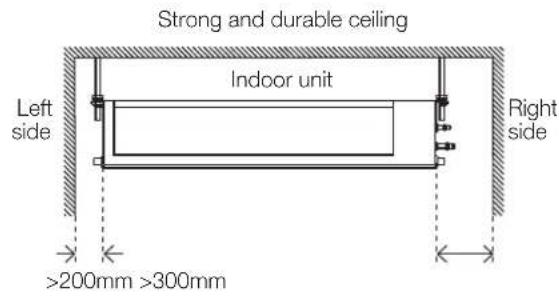
text_image
Strong and durable ceiling Indoor unit Left side Right side >200mm >300mm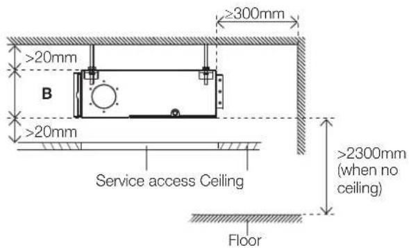
text_image
≥300mm >20mm B >20mm Service access Ceiling >2300mm (when no ceiling) Floor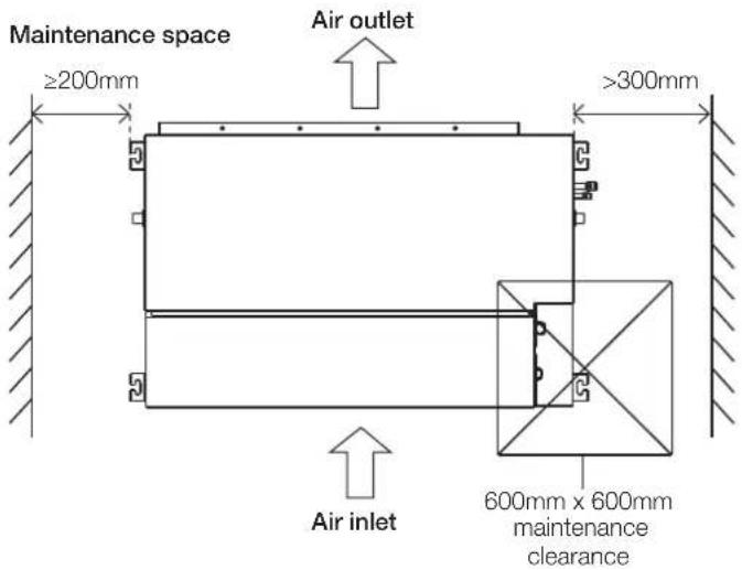
text_image
Maintenance space ≥200mm Air outlet >300mm Air inlet 600mm x 600mm maintenance clearanceStep 2: Hang indoor unit.
- Please refer to the following diagrams to locate the four positioning screw bolt holes on the ceiling. Be sure to mark the places where you will drill ceiling hook holes.
Air outlet dimensions

text_image
A F E B C DAir inlet dimensions

text_image
H G Air filterDescending ventilation opening and mounted hook
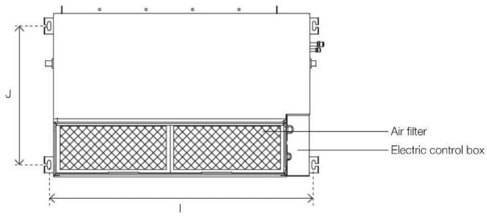
text_image
Air filter Electric control boxUnit: mm
| MODEL(Btu/h) | Outline dimension | Air outletopening size | Air returnopening size | Size ofmounted lug | ||||||
| A B C | D E F G H I J | |||||||||
| KMD09/12 | 700 | 200 | 506 | 450 | 152 | 537 | 186 | 599 | 741 | 360 |
| KMD18 | 880 | 210 | 674 | 600 | 136 | 706 | 190 | 782 | 920 | 508 |
| KMD24 | 1100 | 249 | 774 | 700 | 175 | 926 | 228 | 1001 | 1140 | 598 |
Wood
Place the wood mounting across the roof beams, then install the hanging screw bolts.

text_image
Wood mounting Roof beam Ceiling Hanging screw boltsNew concrete bricks
Inlay or embed the screw bolts.

Blade shape insertion Slide insertion
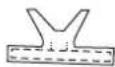
Original concrete bricks
Use an embedding screw bolt, crock, and stick harness.
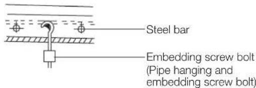
text_image
Steel bar Embedding screw bolt (Pipe hanging and embedding screw bolt)Steel roof beam structure
Install and use the supporting steel angle.

text_image
Hanging screw bolt Hanging bolts Supporting angle steel
AUTION
The unit body must be completely aligned with the hole. Ensure that the unit and the hole are the same size before moving on.
-
Install and fit pipes and wires after you have finished installing the main body. When choosing where to start, determine the direction of the pipes to be drawn out. Especially in cases where there is a ceiling involved, align the refrigerant pipes, drain pipes, and indoor and outdoor lines with their connection points before mounting the unit.
-
Install hanging screw bolts.
-
Cut off the roof beam.
-
Strengthen the point at which the cut was made. Consolidate the roof beam.
-
After you select an installation location, align the refrigerant pipes, drain pipes, as well as indoor and outdoor wires with their connection points before mounting the unit.
- Drill 4 holes 100mm deep at the ceiling hook positions in the internal ceiling. Be sure to hold the drill at a 90° angle to the ceiling.
- Secure the bolt using the washers and nuts provided.
- Install the four suspension bolts.
- Mount the indoor unit with at least two people to lift and secure it. Insert suspension bolts into the unit's hanging holes. Fasten them using the washers and nuts provided.
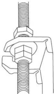
natural_image
Technical line drawing of a mechanical clamp or fastener assembly (no text or symbols)- Mount the indoor unit onto the hanging screw bolts with a block. Position the indoor unit flat using a level indicator to prevent leaks.
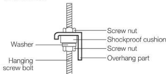
text_image
Screw nut Shockproof cushion Screw nut Overhang part Washer Hanging screw boltNOTE: Confirm the minimum drain tilt is 1/100 or more.
Step 3: Duct and accessories installation
- Install the filter (optional) according to the size of the air inlet.
- Install the canvas tie-in between the body and duct.
- The air inlet and air outlet duct should be far enough apart to avoid air passage short-circuit.
- Connect the duct according to the following diagram:

text_image
Isolation booth Canvas tie-in Air outlet Air inletAir filterChecking access- Refer to the following static pressure guidelines when installing the indoor unit.
Model Static pressure (Pa/in.wg)
| KMD09 0 - 50/0 - 0.2 | |
| KMD12 0 - 50/0 - 0.2 | |
| KMD18 0 - 100/0 - 0.4 | |
| KMD24 0 - 160/0 - 0.64 |
Change the fan motor air static pressure according to external duct static pressure.
NOTE:
- Do not place the connecting duct weight on the indoor unit.
- When connecting the duct, use a non-flammable canvas tie-in to prevent vibrating.
- Insulation foam must be wrapped outside the duct to avoid condensate. An internal duct under-layer can be added to reduce noise, if the end-user requires.
NOTE: All the figures in this manual are for demonstration purposes only. The air conditioner you have purchased may be slightly different in design, though similar in shape.
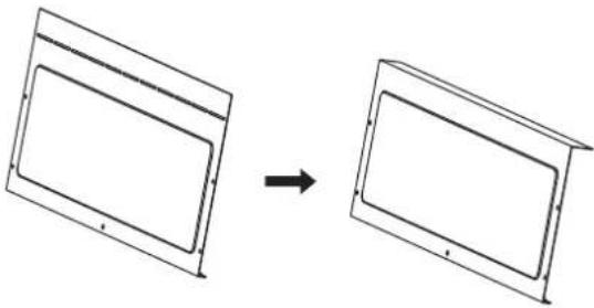
Step 4: Adjust the air inlet direction (from rear side to under-side)
- Take off the ventilation panel and flange.

text_image
Air return flange Ventilation panelBend the rear ventilation panel 90 degrees along the dotted line into a descending ventilation panel. (some models)
natural_image
Diagram showing two rectangular panels transforming into a larger empty panel, with an arrow indicating transformation (no text or symbols present)- Change the mounting positions of the ventilation panel and air return flange.
- When installing the filter mesh, fit it into the flange as illustrated in the following figure.
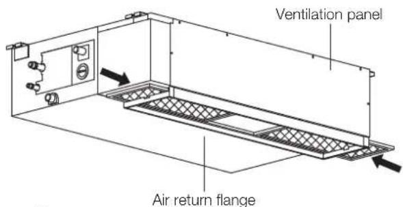
text_image
Ventilation panel Air return flangeOr

text_image
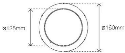
Ventilation panel Air return flangeStep 5: Fresh air duct installation
Dimension
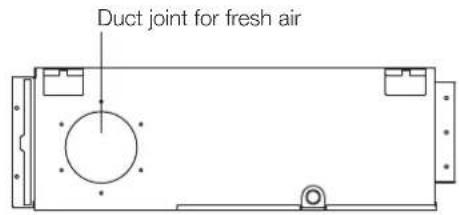
text_image
Duct joint for fresh airKMD09, 12
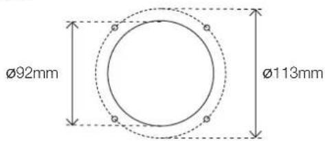
text_image
Ø92mm Ø113mmKMD18, 24
text_image
Ø125mm Ø160mmStep 6: Motor and drain pump maintenance
The rear ventilated panel is used as an example.
Motor maintenance
- Take off the ventilated panel.
- Take off the blower housing.
- Take off the motor.

text_image
Motor Blower housing Ventilated panelPump maintenance
- Remove four screws from the drain pump.
- Unplug the pump power supply and water level switch cable.
- Detach the pump.
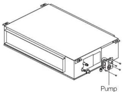
natural_image
Technical line drawing of a rectangular electronic device with labeled components (no text or symbols beyond 'Pump')Step 7: Drill wall hole for connective piping
- Determine the location of the wall hole based on the location of the outdoor unit.
- Using a 65mm or 90mm (depending on models) core drill, drill a hole in the wall. Make sure that the hole is drilled at a slight downward angle, so that the outdoor end of the hole is lower than the indoor end by about 12mm. This will ensure proper water drainage.
- Place the protective wall cuff in the hole. This protects the edges of the hole and will help seal it when you finish the installation process.
CAUTION
When drilling the wall hole, make sure to avoid wires, plumbing, and other sensitive components.

text_image
Wall Outdoor Indoor ≈ 12mmStep 8: Connect drain hose
The drainpipe is used to drain water away from the unit. Improper installation may cause unit and property damage.

CAUTION
• Insulate all piping to prevent condensation, which could lead to water damage.
- If the drainpipe is bent or installed incorrectly, water may leak and cause a water-level switch malfunction.
- In HEAT mode, the outdoor unit will discharge water. Ensure that the drain hose is placed in an appropriate area to avoid water damage and slippage.
- Do not pull the drainpipe forcefully. This could disconnect it.
NOTE ON PURCHASING PIPES
Installation requires a polyethylene tube (exterior diameter = 37 - 3mm, interior diameter = 32mm), which can be obtained at your local hardware store or dealer.
Indoor drainpipe installation
Install the drainpipe as illustrated in the following figure.
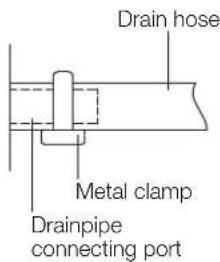
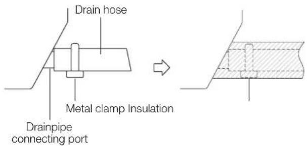
text_image
Drain hose Metal clamp Drainpipe connecting port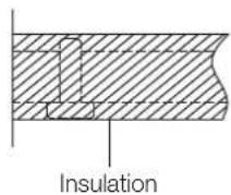
- Cover the drainpipe with heat insulation to prevent condensation and leakage.
- Attach the mouth of the drain hose to the unit's outlet pipe. Sheath the mouth of the hose and clip it firmly with a pipe clasp.

text_image
1000 - 1500mm Lean over 1/50NOTE ON DRAINPIPE INSTALLATION
- When using an extended drainpipe, tighten the indoor connection with an additional protection tube. This prevents it from pulling loose.
- The drainpipe should slope downward at a gradient of at least 1/100 to prevent water from flowing back into the air conditioner.
- To prevent the pipe from sagging, space hanging wires every 1000 - 1500mm.
- If the outlet of the drainpipe is higher than the body's pump joint, use a lift pipe for the indoor unit's exhaust outlet. The lift pipe must be installed no higher than 550mm from the ceiling board. The distance between the unit and the lift pipe must be less than 200mm. Incorrect installation could cause water to flow back into the unit and flood.
- To prevent air bubbles, keep the drain before the riser level or sloping slightly up.
Drainpipe installation for units with a pump
NOTE: When connecting multiple drainpipes, install the pipes as illustrated.
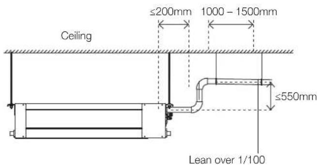
text_image
Ceiling ≤200mm 1000 - 1500mm ≤550mm Lean over 1/100Units with a pump
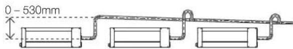
text_image
0 - 530mmDrainpipe connecting port
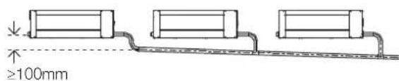
text_image
≥100mm- Pass the drain hose through the wall hole. Units with a pump. Make sure the water drains to a safe location where it will not cause water damage or a slipping hazard.
NOTE: The drainpipe outlet should be at least 50mm above the ground. If it touches the ground, the unit may become blocked and malfunction. If you discharge the water directly into a sewer, make sure that the drain has a U or S pipe to catch odours that might otherwise come back into the house.
Drainage test
Check whether the drainpipe is unhindered. This test should be performed on newly built houses before the ceiling is painted.
Units without a pump.
Fill the water pan with 2 litres of water. Check that the drainpipe is unhindered.

text_image
Stow tubeNOTE:
If drain pump spigot not used, drain pump will still engage if the drain tray fills and activates water level sensor. This can lead to water leakage. Possible actions to avoid water leakage:
- Disconnect power to drain pump.
- Plumb drain pump spigot into gravity fed drain
Units with a pump
- Remove the test cover.
Fill the water pan with 2 litres of water.
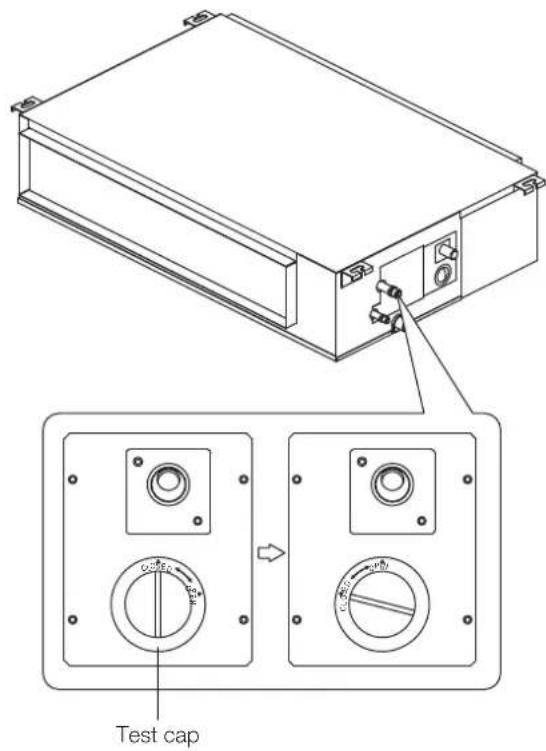
text_image
Test cap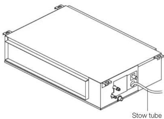
natural_image
Technical line drawing of a rectangular electronic device with a stow tube and internal components (no text or symbols)- Turn on the unit in COOLING mode. You will hear the drain pump. Check whether the water is discharged properly (a 1 minute lag is possible, depending on the length of the drain pipe), Check whether water leaks from the joints.
- Turn off the air conditioner and put the cap back on.
5. KMD wiring

WARNING
BEFORE PERFORMING ANY ELECTRICAL OR WIRING WORK, TURN OFF THE MAIN POWER TO THE SYSTEM.

BEFORE PERFORMING ANY ELECTRICAL WORK, READ THESE REQUIREMENTS
- All wiring must comply with local and national electrical codes, regulations and must be installed by a licensed electrician.
- All electrical connections must be made according to the Electrical Connection Diagram located on the panels of the indoor and outdoor units.
- If there is a serious safety issue with the power supply, stop work immediately. Explain your reasoning to the client, and refuse to install the unit until the safety issue is properly resolved.
- Power voltage should be within 90 – 110% of rated voltage. Insufficient power supply can cause malfunction, electrical shock, or fire.
- If connecting power to fixed wiring, install a surge protector and main power switch with a capacity of 1.5 times the maximum current of the unit.
- If connecting power to fixed wiring, a switch or circuit breaker that disconnects all poles and has a contact separation of at least 3mm must be incorporated in the fixed wiring. The qualified technician must use an approved circuit breaker or switch.
- Only connect the unit to an individual branch circuit outlet. Do not connect another appliance to that outlet.
-
Make sure to properly ground the air conditioner.
-
Every wire must be firmly connected. Loose wiring can cause the terminal to overheat, resulting in product malfunction and possible fire.
- Do not let wires touch or rest against refrigerant tubing, the compressor, or any moving parts within the unit.
- If the unit has an auxiliary electric heater, it must be installed at least 1 metre away from any combustible materials.
- To avoid getting an electric shock, never touch the electrical components soon after the power supply has been turned off. After turning off the power, always wait 10 minutes or more before you touch the electrical components.
- Make sure that you do not cross your electrical wiring with your signal wiring. This may cause distortion and interference.
- The unit must be connected to the main outlet. Normally, the power supply must have a impedance of 32 ohms.
- No other equipment should be connected to the same power circuit.
- Connect the outdoor wires before connecting the indoor wires.
Indoor unit wiring

WARNING
Before performing any electrical or wiring work, turn off the main power to the system.
Electrical requirement
The indoor unit is powered by the outdoor unit. Do not power indoor unit from separate power source.

WARNING
Standard for electrical wiring and equipment differs in each country or region. Before you start electrical working, confirm related regulations, codes or standards.
| Cable Conductor size (mm2) | Type Remarks | ||
| Interconnect power cable | 1.5 Type | 60245 IEC 57 | 2 core + Earth (Ground) 1 ∅ 230 V |
| Cable Conductor size (mm2) | Type Remarks | ||
| Signal cable | 1.0 Type | 60245 IEC 57 | 2 core Shielded |
Cable length: Limit voltage drop to less than 2%. Increase cable gauge if voltage drop is 2% or more.
If the interconnect cable exceeds 30M in length 2.5mm thick cable should be used.
The cable specifications are based on the assumption that a metal or plastic conduit is used with no more than three cables contained in a conduit and a voltage drop of 2%.
Preparing cable
- Selecting cable: Select the interconnect power cable in accordance with the specifications mentioned: 3-Core 1.5mm² or more* Interconnect Power cable, conformed with 60245 IEC57. When selecting the interconnect power cable length, make sure the voltage drop is less than 2%. If wire voltage drop is above 2% increase interconnect power cable wire diameter/thickness.
- Arrange each wire length as shown. Make sure that each wire is stripped 10mm from the end.
- Attach round crimp-type terminal to each wire as shown. Select the size of round crimp-type terminal after considering the specifications of terminal block and wire diameter.
Interconnect power cable

text_image
30mm or more Earth wire 40mm or moreSignal cable

text_image
30mm or more 40mm or moreWire end
text_image
10mm Round crimp type terminal SleeveIndoor unit wiring

CAUTION
- While connecting the wires, please strictly follow the wiring diagram.
-
The refrigerant circuit can become very hot. Keep the interconnection cable away from the copper tube.
-
Prepare the power and signal cables for connection a. Using wire strippers, strip the rubber jacket from both ends of the power and signal cable to reveal about 150mm of the wires.
b. Strip the insulation from the ends of the wires.
c. Using a wire crimper, crimp the u-lugs to the ends of the wires. -
Open the front panel of the indoor unit. Using a screwdriver, remove the cover of the electric control box on your indoor unit.
-
Thread the power cable and the signal cable through the wire outlet.
-
Connect the u-lugs to the terminals. Match the wire colours/labels with the labels on the terminal block. Firmly screw the u-lug of each wire to its corresponding terminal. Refer to the Serial Number and Wiring Diagram located on the cover of the electric control box.
-
Clamp down the cable with the cable clamp. The cable must not be loose or pull on the u-lugs.
-
Locate the factory test cable. This has two 5-conductor cream-coloured female connectors plugged into connector CN14 of the indoor unit printed circuit board (PCB) using a 10-conductor white plug.
-
Remove the factory test cable from the white-coloured connector CN14 of the indoor PCB.
-
Plug the cable from the cassette cover panel with the same type of white connector into CN14 of the indoor PCB.
-
Ensure the control panel cable from the cassette cover panel is attached to the black 10-conductor connector plug.
-
Re-attach the electrical enclosure cover being careful not to squash the wiring.
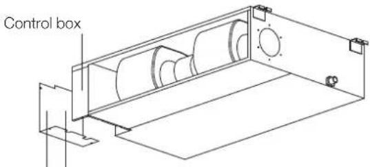
text_image
Control boxWiring diagram Connective wiring diagram
Magnetic ring (if supplied and packed with the accessories)
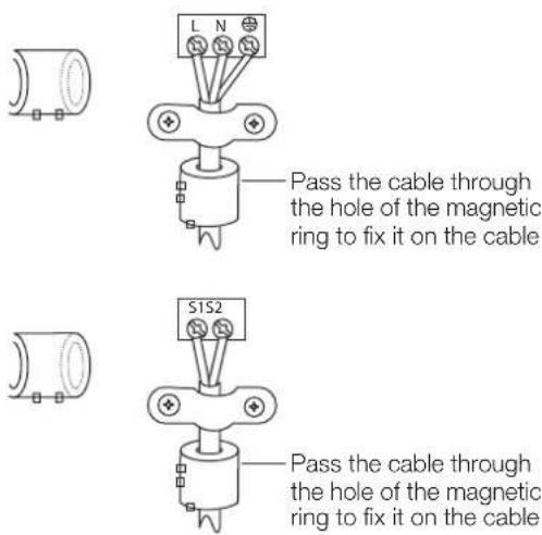
text_image
L N Pass the cable through the hole of the magnetic ring to fix it on the cable S1S2 Pass the cable through the hole of the magnetic ring to fix it on the cable
text_image
OUTDOOR UNIT L1 2 L3 S S2 N 1L N INDOOR UNIT6. KMD test run
Before test run
A test run must be performed after the entire system has been completely installed. Confirm the following points before performing the test:
- Indoor and outdoor units are properly installed.
- Piping and wiring are properly connected.
- No obstacles near the inlet and outlet of the unit that might cause poor performance or product malfunction.
- Refrigeration system does not leak.
- Drainage system is unimpeded and draining to a safe location.
- Heating insulation is properly installed.
- Grounding wires are properly connected.
- Length of the piping and additional refrigerant stow capacity have been recorded.
- Power voltage is the correct voltage for the air conditioner.

CAUTION
Failure to perform the test run may result in unit damage, property damage, or personal injury.
Test run instructions
- Open both the liquid and gas stop valves.
- Turn on the main power switch and allow the unit to warm up.
- Set the air conditioner to COOL mode.
-
For the indoor unit
a. Ensure the remote control and its buttons work properly.
b. Ensure the louvres move properly and can be changed using the remote control.
c. Double check to see if the room temperature is being registered correctly.
d. Ensure the indicators on the remote control and the display panel on the indoor unit work properly.
e. Ensure the manual buttons on the indoor unit work properly.
f. Check to see that the drainage system is unimpeded and draining smoothly.
g. Ensure there is no vibration or abnormal noise during operation. -
For the outdoor unit
a. Check to see if the refrigeration system is leaking.
b. Make sure there is no vibration or abnormal noise during operation.
c. Ensure the wind, noise, and water generated by the unit do not disturb your neighbours or pose a safety hazard.
- Drainage test
a. Ensure the drainpipe flows smoothly. For installations in new buildings, you should perform this test before finishing the ceiling.
b. Remove the test cover. Add 2,000ml of water to the tank through the attached tube.
c. Turn on the main power switch and run the air conditioner in COOL mode.
d. Listen to the sound of the drain pump to see if it makes any unusual noises.
e. Check to see that the water is discharged. It may take up to one minute before the unit begins to drain, depending on the drainpipe.
f. Make sure that there are no leaks in any of the piping.
g. Stop the air conditioner. Turn off the main power switch and reinstall the test cover.
NOTE: If the unit malfunctions or does not operate according to your expectations, please refer to the Troubleshooting section of the Owner's Manual before calling customer service.
The design and specifications are subject to change without prior notice for product improvement. Consult with the sales agency or manufacturer for details. Any updates to the manual will be uploaded to the service website. Please check for the latest version.
7. KMD error codes
Error display (indoor unit)
| Running lamp | Timer lamp | Display Information Solution | ||
| 1 time | × | EH 00/EH 0A Indoor unit EEPROM parameter error TS01-IDU | ||
| 2 times | × | EL 01 Indoor/outdoor unit communication error TS02-S-INV | ||
| 3 times | × | EH 02 Zero-crossing signal detection error TS03 | ||
| 4 times | × | EH 03 The indoor fan speed is operating outside of the normal range TS04-S-IDU | ||
| 5 times | × | EC 51 Outdoor unit EEPROM parameter error TS01-ODU | ||
| 5 times | × | EC 52 Condenser coil temperature sensor T3 is in open circuit or has short circuited | TS05-ODU | |
| 5 times | × | EC 53 Outdoor room temperature sensor T4 is in open circuit or has short circuited | TS05-ODU | |
| 5 times | × | EC 54 Compressor discharge temperature sensor TP is in open circuit or has short circuited | TS05-ODU | |
| 5 times | × | EC 56 Evaporator coil outlet temperature sensor T2B is in open circuit or has short circuited (for free-match indoor units) | TS05-ODU | |
| 6 times | × | EH 60 Indoor room temperature sensor T1 is in open circuit or has short circuited | TS05-IDU | |
| 6 times | × | EH 61 Evaporator coil middle temperature sensor T2 is in open circuit or has short circuited | TS05-IDU | |
| 12 times | × | EC 07 The outdoor fan speed is operating outside of the normal range TS04-ODU | ||
| 9 times | × | EH 0b Indoor PCB/Display board communication error TS07 | ||
| 8 times | × | EL 0C Refrigerant leakage detection TS06-INV | ||
| 7 times | △ | PC 00 | IPM malfunction or IGBT over-strong current protection | TS09-S |
| 2 times | △ | PC 01 Over voltage or over low voltage protection | TS10-S | |
| 3 times | △ | PC 02 Top temperature protection of compressor or High temperature protection of IPM module or High pressure protection | TS11-S-INV | |
| 5 times | △ | PC 04 Inverter compressor drive error | TS12-S | |
| 1 time | △ | PC 08 Current overload protection | TS08-S | |
| 6 times | △ | PC 40 Communication error between outdoor main chip and compressor driven chip | TS33 | |
| 7 times | △ | PC 03 Low pressure protection | TS13-INV | |
| 1 time | ○ | Indoor units mode conflict (match with multi outdoor unit) | TS14 | |
o on
× off
△ flash
MULTI CASSETTE AIR CONDITIONER
KMC Multi Cassette Air Conditioner
KMC09 | KMC12 | KMC18
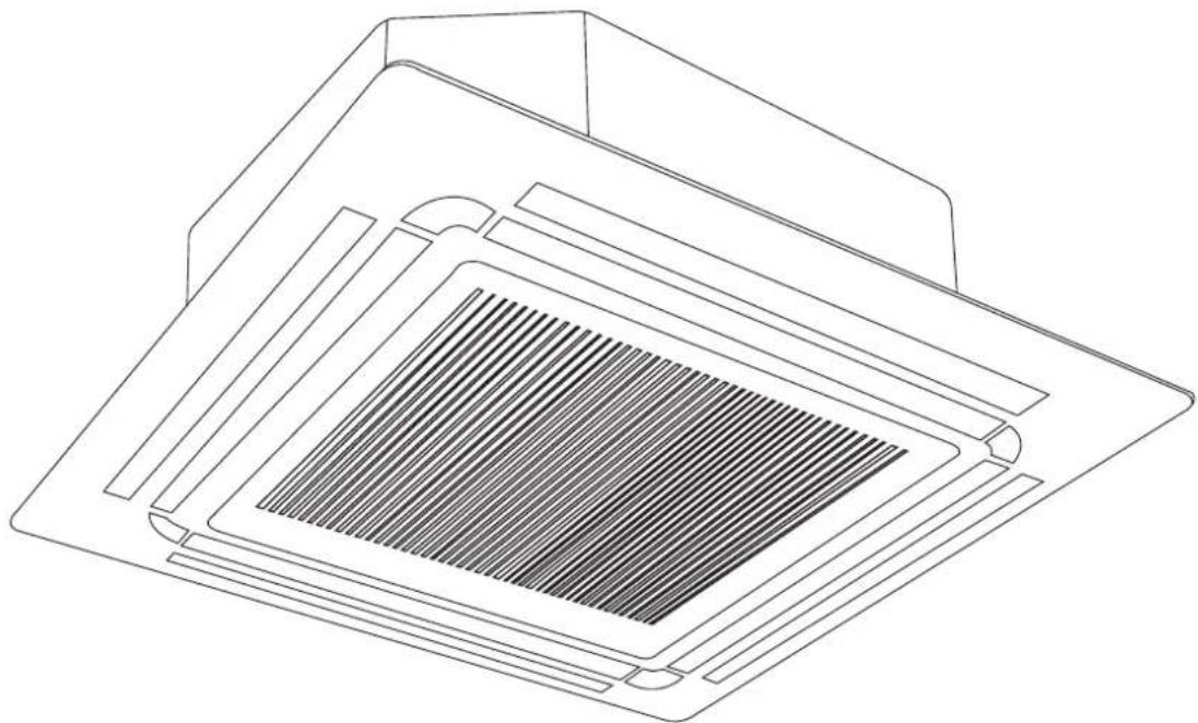
natural_image
Technical line drawing of a microchip or solar panel with a grid-patterned cover (no text or symbols)1. KMC accessories
The air conditioning system comes with the following accessories. Use all of the installation parts and accessories to install the air conditioner. Improper installation may result in water leakage, electrical shock and fire, or cause the equipment to fail.
| Name of accessories Qty (pc) Shape Name of accessories Qty (pc) Shape | |||||
| Owner's and Controller Manual | 1 |  | Suspension bolt 4 |  | |
| Installation Manual 1 |  | Installation paper template | 1 |  | |
| Soundproof/insulation sheath | 1 |  | Drain joint 1 |  | |
| Soundproof/insulation sheath | 1 |  | Seal ring 1 |  | |
| Drain connection 1 Copper nut 2 |  |  | |||
| Worm drive clamp | 1 |  | Magnetic ring – wrap the electric wires S1 & S2 around the magnetic ring twice | 1 |  |
| Ceiling hook | 4 |  | Magnetic ring – hitch it on the connective cable between indoor unit and outdoor unit after installation | Varies by model |  |
Important note
This appliance must be installed in accordance with:
Manufacturer's Installation Instructions
Current AS/NZS 3000, AS/NZS 5149
Local Regulations and Municipal Building Codes including local OH&S requirements
This appliance must be installed, maintained, and removed only by an Authorised Person.
For continued safety of this appliance, it must be installed and maintained in accordance with the manufacturer's Instructions.
2. KMC installation summary
Install the indoor unit Install the drainpipe Install the outdoor unit
Connect the signal wires Connect the wires
Connect the refrigerant pipes
Pressure test and evacuation Install the front panel Perform a test run
3. KMC unit parts
NOTE: The installation must be performed in accordance with Australian guidelines. The installation may be slightly different in different areas.
Compact four-way cassette type
1 Drain pump (drain water from indoor unit
2 Drain hose
3 Air out
4 Air in
5 Air-in grille
6 Display panel
7 Remote control
text_image
pe 1 2 3 4 5 6 7 One-five One-four One-three One-twin One-twinNote on illustrations
Illustrations in this manual are for explanatory purposes. The actual shape of your indoor unit may be slightly different.
4. KMC indoor unit installation
Installation instructions – indoor unit
NOTE: Panel installation should be performed after piping and wiring have been completed.
Step 1: Select installation location
Before installing the indoor unit, you must choose an appropriate location. The following are standards that will help you choose an appropriate location for the unit.
Proper installation locations meet the following standards:
√ Enough room exists for installation and maintenance.
√ Enough room exists for the connecting the pipe and drainpipe.
√ The ceiling is horizontal and its structure can sustain the weight of the indoor unit.
√ The air inlet and outlet are not blocked.
√ The airflow can fill the entire room.
√ There is no direct radiation from heaters.
DO NOT install unit in the following locations:
× Areas with oil drilling or fracking.
× Coastal areas with high salt content in the air.
× Areas with caustic gases in the air, such as hot springs.
× Areas that experience power fluctuations, such as factories.
✗ Enclosed spaces, such as cabinets.
✗ Kitchens that use natural gas.
× Areas with strong electromagnetic waves.
× Areas that store flammable materials or gas.
× Rooms with high humidity, such as bathrooms or laundry rooms.
Recommended distances between the indoor unit and the ceiling
The distance between the mounted indoor unit and the internal ceiling should meet the following specifications.

text_image
Ceiling H A Front panel Ceiling board B (Ceiling hole) >2500mm GroundDistance from ceiling relative to height of indoor unit
| Type Model A (mm) H (mm) B (mm) | |||
| KMC | KMC09 245 > 275 | ||
| 880KMC12 205 > 235 | |||
| KMC18 245 > 275 | |||
Step 2: Hang indoor unit
-
Use the included paper template to cut a rectangular hole in the ceiling, leaving at least 1000mm on all sides.
-
The cut hole size should be 40mm larger than the body size. Be sure to mark the areas where ceiling hook holes will be drilled.
KMC models ceiling hole size

text_image
Drain hose side Refrigerant piping side 523mm (Suspension bolt) 570mm (Body) 600mm (Ceiling opening) 647mm (Panel) 545mm (Suspension bolt) 570mm (Body) 600mm (Ceiling opening) 647mm (Panel)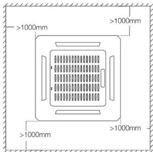
text_image
>1000mm >1000mm >1000mm >1000mmKMC compact models ceiling hole size
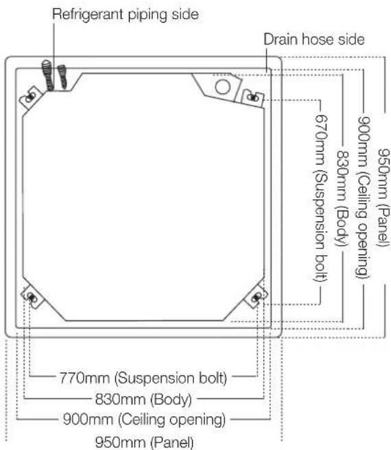
text_image
Refrigerant piping side Drain hose side 670mm (Suspension bolt) 830mm (Body) 900mm (Ceiling opening) 950mm (Panel) 770mm (Suspension bolt) 830mm (Body) 900mm (Ceiling opening) 950mm (Panel)
AUTION
The unit body should align perfectly with the hole. Ensure that the unit and the hole are the same size before moving on.
- Drill 4 holes 50mm deep at the ceiling hook positions in the internal ceiling. Be sure to hold the drill at a 90° angle to the ceiling.
- Using a hammer, insert the ceiling hooks into the pre-drilled holes. Secure the bolt using the included washers and nuts.
- Install the four suspension bolts.

natural_image
Line drawing of a vertical mechanical device with a flanged handle and base (no text or symbols)- Mount the indoor unit. You will need two people to lift and secure it. Insert suspension bolts into the unit's hanging holes. Fasten them using the included washers and nuts.

natural_image
Technical line drawing of a mechanical clamp or fastener assembly (no text or symbols)NOTE: The bottom of the unit should be 10 – 18mm higher than the ceiling board. Generally, L (indicated in the following figure) should be half the length of the suspension bolt or long enough to prevent the nuts from coming off.

text_image
IL Main body 10 - 18mmCeiling board
AUTION
Ensure that the unit is completely level. Improper installation can cause the drain pipe to back up into the unit or water leakage.
NOTE: Ensure that the indoor unit is level. The unit is equipped with a built-in drain pump and float switch. If the unit is tilted against the direction of condensate flows (the drainpipe side is raised), the float switch may malfunction and cause water to leak.
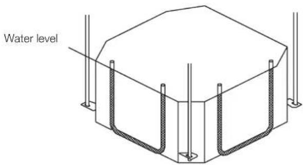
text_image
Water levelNote for new home installation
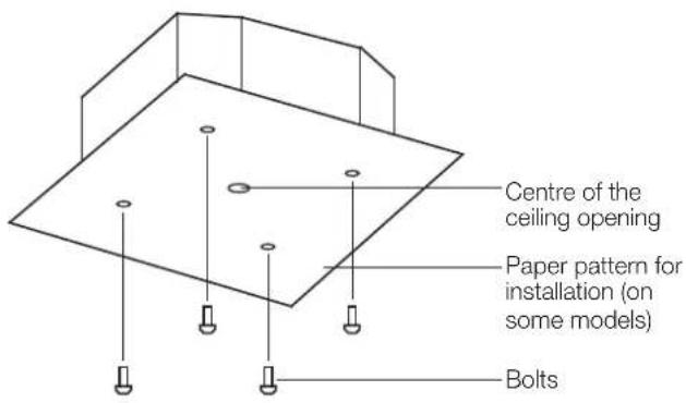
When installing the unit in a new home, the ceiling hooks can be embedded in advance. Make sure that the hooks do not come loose due to concrete shrinkage. After installing the indoor unit, fasten the installation paper template onto the unit with bolts to determine in advance the dimension and position of the opening on the ceiling. Follow the instructions above for the remainder of the installation.
Step 3: Drill wall hole for connective piping
- Determine the location of the wall hole based on the location of the outdoor unit.
- Using a 65mm or 90mm (depending on models) core drill, drill a hole in the wall. Make sure that the hole is drilled at a slight downward angle, so that the outdoor end of the hole is lower than the indoor end by about 12mm. This will ensure proper water drainage.
- Place the protective wall cuff in the hole. This protects the edges of the hole and will help seal it when you finish the installation process.

CAUTION
When drilling the wall hole, make sure to avoid wires, plumbing, and other sensitive piping or cables.
text_image
Centre of the ceiling opening Paper pattern for installation (on some models) Bolts
text_image
Wall Outdoor Indoor ≈ 12mmStep 4: Connect drain hose
The drainpipe is used to drain water away from the unit. Improper installation may cause unit and property damage.

CAUTION
• Insulate all piping to prevent condensation, which could lead to water damage.
- If the drainpipe is bent or installed incorrectly, water may leak and cause a water-level switch malfunction.
- In HEAT mode, the outdoor unit will discharge water. Ensure that the drain hose is placed in an appropriate area to avoid water damage and slippage.
- Do not pull the drainpipe forcefully. This could disconnect it.
Note on purchasing drain pipes
Installation requires a polyethylene tube (exterior diameter = 37 - 39mm, interior diameter = 32mm).
Indoor drain pipe installation
Install the drainpipe as illustrated in the following figure.
text_image
Drain hose Metal clamp Insulation Drainpipe connecting port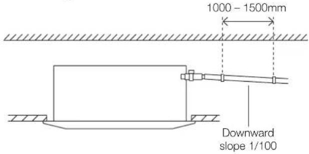
text_image
1000 - 1500mm Downward slope 1/100Note on drainpipe installation
- When using an extended drainpipe tighten the indoor connection with an additional protection tube to prevent it from pulling loose.
- The drainpipe should slope downward at a gradient of at least 1/100 to prevent water from flowing back into the air conditioner.
- To prevent the pipe from sagging, space hanging wires every 1000 – 1500mm.
- If the outlet of the drainpipe is higher than the body's pump joint, provide a lift pipe for the exhaust outlet of the indoor unit. The lift pipe must be installed no higher than 750mm from the ceiling board and the distance between the unit and the lift pipe must be less than 300mm. Incorrect installation could cause water to flow back into the unit and flood.
- To prevent air bubbles, keep the drain hose level or slightly tiled up (<75mm).
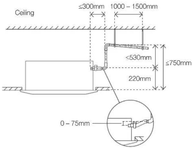
text_image
Ceiling ≤300mm 1000 - 1500mm ≤530mm ≤750mm 220mm 0 - 75mmNOTE: When connecting multiple drainpipes, install the pipes as illustrated in the following figure.
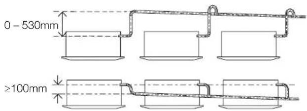
text_image
0 - 530mm ≥100mmPass the drain hose through the wall hole. Make sure the water drains to a safe location where it will not cause water damage or a slipping hazard.
NOTE: The drainpipe outlet should be at least 50mm above the ground. If it touches the ground, the unit may become blocked and malfunction. If you discharge the water directly into a sewer, make sure that the drain has a U or S pipe to catch odours that might otherwise come back into the house.
5. KMC wiring

WARNING
BEFORE PERFORMING ANY ELECTRICAL OR WIRING WORK, TURN OFF THE MAIN POWER TO THE SYSTEM.

BEFORE PERFORMING ANY ELECTRICAL WORK, READ THESE REQUIREMENTS
- All wiring must comply with local and national electrical codes, regulations and must be installed by a licensed electrician.
- All electrical connections must be made according to the Electrical Connection Diagram located on the panels of the indoor and outdoor units.
- If there is a serious safety issue with the power supply, stop work immediately. Explain your reasoning to the client, and refuse to install the unit until the safety issue is properly resolved.
- Power voltage should be within 90 – 110% of rated voltage. Insufficient power supply can cause malfunction, electrical shock, or fire.
- If connecting power to fixed wiring, install a surge protector and main power switch with a capacity of 1.5 times the maximum current of the unit.
- If connecting power to fixed wiring, a switch or circuit breaker that disconnects all poles and has a contact separation of at least 3mm must be incorporated in the fixed wiring. The qualified technician must use an approved circuit breaker or switch.
- Only connect the unit to an individual branch circuit outlet. Do not connect another appliance to that outlet.
-
Make sure to properly ground the air conditioner.
-
Every wire must be firmly connected. Loose wiring can cause the terminal to overheat, resulting in product malfunction and possible fire.
- Do not let wires touch or rest against refrigerant tubing, the compressor, or any moving parts within the unit.
- If the unit has an auxiliary electric heater, it must be installed at least 1000mm away from any combustible materials.
- To avoid getting an electric shock, never touch the electrical components soon after the power supply has been turned off. After turning off the power, always wait 10 minutes or more before you touch the electrical components.
- Make sure that you do not cross your electrical wiring with your signal wiring. This may cause distortion and interference.
- The unit must be connected to the main outlet. Normally, the power supply must have a impedance of 32 ohms.
- No other equipment should be connected to the same power circuit.
- Connect the outdoor wires before connecting the indoor wires.
Indoor unit wiring

WARNING
Before performing any electrical or wiring work, turn off the main power to the system.
Electrical requirement
The indoor unit is powered by the outdoor unit. Do not power indoor unit from separate power source.

WARNING
Standard for electrical wiring and equipment differs in each country or region. Before you start electrical working, confirm related regulations, codes or standards.
| Cable Conductor size (mm2) | Type Remarks | ||
| Interconnect power cable | 1.5 Type | 60245 IEC 57 | 2 core + Earth (Ground) 1 ∅ 230 V |
| Cable Conductor size (mm2) | Type Remarks | ||
| Signal cable | 1.0 Type | 60245 IEC 57 | 2 core Shielded |
Cable length: Limit voltage drop to less than 2%. Increase cable gauge if voltage drop is 2% or more.
If the interconnect cable exceeds 30000mm in length 2.5mm thick cable should be used.
The cable specifications are based on the assumption that a metal or plastic conduit is used with no more than three cables contained in a conduit and a voltage drop of 2%.
Preparing cable
- Selecting cable: Select the interconnect power cable in accordance with the specifications mentioned: 3-Core 1.5mm² or more* Interconnect Power cable, conformed with 60245 IEC57. When selecting the interconnect power cable length, make sure the voltage drop is less than 2%. If wire voltage drop is above 2% increase interconnect power cable wire diameter/thickness.
- Arrange each wire length as shown. Make sure that each wire is stripped 10mm from the end.
- Attach round crimp-type terminal to each wire as shown. Select the size of round crimp-type terminal after considering the specifications of terminal block and wire diameter.
Interconnect power cable
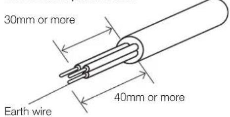
text_image
30mm or more Earth wire 40mm or moreSignal cable
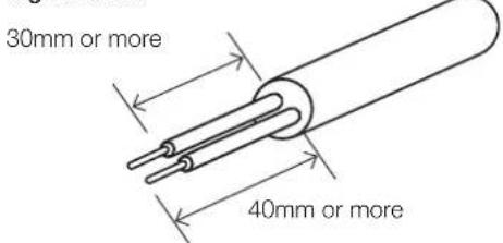
text_image
30mm or more 40mm or moreWire end
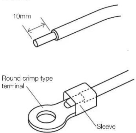
text_image
10mm Round crimp type terminal SleeveIndoor unit wiring

CAUTION
- While connecting the wires, please strictly follow the wiring diagram.
- The refrigerant circuit can become very hot. Keep the interconnection cable away from the copper tube.

text_image
Control box Wire outlet Control box Wiring diagram Connective wiring diagram-
Prepare the power and signal cables for connection
a. Using wire strippers, strip the rubber jacket from both ends of the power and signal cable to reveal about 150mm of the wires.
b. Strip the insulation from the ends of the wires.
c. Using a wire crimper, crimp the u-lugs to the ends of the wires. -
Open the front panel of the indoor unit. Using a screwdriver, remove the cover of the electric control box on your indoor unit.
-
Thread the power cable and the signal cable through the wire outlet.
-
Connect the u-lugs to the terminals. Match the wire colours/labels with the labels on the terminal block. Firmly screw the u-lug of each wire to its corresponding terminal. Refer to the Serial Number and Wiring Diagram located on the cover of the electric control box.
-
Clamp down the cable with the cable clamp. The cable must not be loose or pull on the u
- Locate the factory test cable. This has two 5-conductor cream-coloured female connectors plugged into connector CN14 of the indoor unit printed circuit board (PCB) using a 10-conductor white plug.
- Remove the factory test cable from the white-coloured connector CN14 of the indoor PCB.
- Plug the cable from the cassette cover panel with the same type of white connector into CN14 of the indoor PCB.
- Ensure the control panel cable from the cassette cover panel is attached to the black 10-conductor connector plug.
- Re-attach the electrical enclosure cover being careful not to squash the wiring.
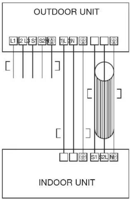
text_image
OUTDOOR UNIT L1 2 L3 S 1 2 N 1 L 2 N 1 2 N INDOOR UNIT6. KMC panel installation

CAUTION
If the unit is not hung correctly and a gap exists, the unit's height must be adjusted to ensure proper function. The unit's height can be adjusted by loosening the upper nut, and adjusting the lower nut.
Multi cassette models
Step 1: Remove the front grille.
- Push both of the tabs towards the middle simultaneously to unlock the hook on the grille.

text_image
Grille hook Grille hook- Hold the grille at a 45^ angle, lift it up slightly and detach it from the main body.
Step 2: Install the panel.
Align the indicator on the decoration panel to the indicator on the unit. Attach the decoration panel to the unit with the supplied screws as shown in figure below.

text_image
Decoration panel Screws (M5) (supplied with the panel)After installing the decoration panel, ensure that there is no space between the unit body and decoration panel. Otherwise air may leak through the gap and cause dewdrop. (See figure below)

natural_image
Simple line drawing of a floating platform with arrows indicating motion, no text or symbols present
natural_image
Pure mechanical diagram showing a structural component with rotational arrows, no text or symbols presentStep 3: Mount the intake grille.
Ensure that the buckles at the back of the grille are properly seated in the groove of the panel.

natural_image
Diagram of a printer with an arrow indicating a cable or cable being inserted, showing internal components (no text or symbols present)Step 4: Connect the 2 wires of the decoration panel to the mainboard of the unit.

text_image
10-core wire5-core wireStep 5: Fasten the control box lid with 2 screws.

natural_image
Line drawing of a microwave oven with internal components and wiring (no text or symbols)Step 6: Close the intake grille, and close the 2 grille hooks.
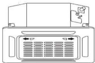
natural_image
Front view of a computer monitor with ventilation grilles and ports (no text or symbols visible)7. KMC test run
Before test run
A test run must be performed after the entire system has been completely installed. Confirm the following points before performing the test:
- Indoor and outdoor units are properly installed.
- Piping and wiring are properly connected.
- No obstacles near the inlet and outlet of the unit that might cause poor performance or product malfunction.
- Refrigeration system does not leak.
- Drainage system is unimpeded and draining to a safe location.
- Heating insulation is properly installed.
- Grounding wires are properly connected.
- Length of the piping and additional refrigerant stow capacity have been recorded.
- Power voltage is the correct voltage for the air conditioner.

CAUTION
Failure to perform the test run may result in unit damage, property damage, or personal injury.
Test run instructions
- Open both the liquid and gas stop valves.
- Turn on the main power switch and allow the unit to warm up.
- Set the air conditioner to COOL mode.
-
For the Indoor Unit
a. Ensure the remote control and its buttons work properly.
b. Ensure the louvres move properly and can be changed using the remote control.
c. Double check to see if the room temperature is being registered correctly.
d. Ensure the indicators on the remote control and the display panel on the indoor unit work properly.
e. Ensure the manual buttons on the indoor unit work properly. -
Drainage test
a. Ensure the drainpipe flows smoothly. For installations in new buildings, you should perform this test before finishing the ceiling.
b. Remove the test cover. Add 2,000ml of water to the tank through the attached tube.
c. Turn on the main power switch and run the air conditioner in COOL mode.
d. Listen to the sound of the drain pump to see if it makes any unusual noises.
e. Check to see that the water is discharged. It may take up to one minute before the unit begins to drain, depending on the drainpipe.
f. Make sure that there are no leaks in any of the piping.
g. Stop the air conditioner. Turn off the main power switch and reinstall the test cover.
- Ensure there is no vibration or abnormal noise during operation
NOTE: If the unit malfunctions or does not operate according to your expectations, please refer to the Troubleshooting section of the Owner's Manual before calling customer service.
8. KMC error codes
| Operation lamp | Timer lamp | Display LED status |
| 1 time | × | E0 Indoor unit EEPROM parameter error |
| 2 times | × | E1 Indoor/outdoor units communication error |
| 4 times | × | E3 Indoor fan speed has been out of control |
| 5 times | × | E4 Indoor room temperature sensor T1 open circuit or short circuit |
| 6 times | × | E5 Evaporator coil temperature sensor T2 open circuit or short circuit |
| 7 times | × | EC Refrigerant leakage detection |
| 1 time | ○ | F0 Overload current protection |
| 2 times | ○ | F1 Outdoor ambient temperature sensor T4 open circuit or short circuit |
| 3 times | ○ | F2 Condenser coil temperature sensor T3 open circuit or short circuit |
| 4 times | ○ | F3 Compressor discharge temperature sensor T5 open circuit or short circuit |
| 5 times | ○ | F4 Outdoor unit EEPROM parameter error |
| 6 times | ○ | F5 Outdoor fan speed has been out of control |
| 1 time | △ | P0 IPM malfunction or IGBT over-strong current protection |
| 2 times | △ | P1 Over voltage or over low voltage protection |
| 3 times | △ | P2 High temperature protection of IPM module or compressor top |
| 5 times | △ | P4 Inverter compressor drive error |
○ light
× off
△ flash
*Fault Symptom: The display board shows a garbled code or a code that is not an error code found in the service manual nor a temperature reading.
Trouble shooting:
Use the remote controller. If the unit does not respond to the remote, the indoor PCB needs to be replaced; if the unit does respond, then the display board needs to be replaced.
MULTI OUTDOOR AIR CONDITIONER
KM Multi Outdoor Unit
KM24 | KM28 | KM46
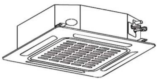
natural_image
Technical line drawing of a microwave oven with cooling fins and a handle (no text or symbols)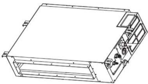
natural_image
Technical line drawing of a rectangular electronic device with internal components and mounting brackets (no text or symbols)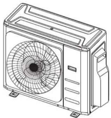
natural_image
Line drawing of a dual air conditioner unit with fan blades and ventilation slots (no text or symbols)
natural_image
Line drawing of a rectangular air conditioner unit with ventilation grilles and cooling fins (no text or symbols)1. KM accessories
The air conditioning system comes with the following accessories. Use all of the installation parts and accessories to install the air conditioner. Improper installation may result in water leakage, electrical shock and fire, or cause the equipment to fail. The items are not included with the air conditioner must be purchased separately.
| Name Shape Adapter Quantity | |||
| Drain joint (some models) |  | 1 | |
| Seal ring (some models) |  | 1 | |
| Reducing flare nut |  | ∅9.52 - ∅12.7 2 | |
| ∅9.52 - ∅15.9 1 | |||
| ∅6.35 - ∅9.52 1 | |||
| ∅12.7 - ∅9.52 1 | |||
| ∅12.7 - ∅15.9 1 | |||
| ∅9.52 - ∅15.9 1 | |||
| ∅9.52 - ∅12.7 1 | |||
| ∅12.7 - ∅9.52 1 | |||
| Pipe adaptor |  | ∅9.52 - ∅12.7 3 | |
| ∅12.7 - ∅15.9 1 | |||
| ∅6.35 - ∅9.52 2 | |||
| ∅12.7 - ∅9.52 2 | |||
| ∅12.7 - ∅15.9 2 | |||
| Owner's and Controller Manual |  | 1 | |
| Installation Manual |  | 1 | |
2. KM installation summary

Install the outdoor unit Connect the refrigerant pipes Connect the wires
Perform a test run
Evacuate the refrigeration system Connect the signal wires
3. KM specifications
Number of units that can be used together Connected units 1 - 5 units
Compressor stop/start frequency Stop time 3 min or more
Power source voltage voltage fluctuation within ±10% of rated voltage
voltage drop during start within ±15% of rated voltage
interval unbalance within ±3% of rated voltage
1 drive 2 1 drive 3 1 drive 4 1 drive 5
Max. length for all rooms 40000mm 60000mm 80000mm 80000mm
Max. length for one indoor unit 25000mm 30000mm 35000mm 35000mm
Max. height difference between indoor and outdoor unit 15000mm 15000mm 15000mm 15000mm
Max. height difference between indoor units 10000mm 10000mm 10000mm 10000mm
When installing multiple indoor units with a single outdoor unit, ensure that the length of the refrigerant pipe and the drop height between the indoor and outdoor units meet the requirements illustrated in the following diagram:

text_image
Outdoor unit Indoor unit Max height difference Indoor unit 15000mm 10000mm 15000mm Indoor unit4. KM unit installation
Install the unit by following local codes and regulations; they may differ slightly between different regions.

text_image
600mm above 300mm from back wall 300mm on left 2000mm in front 600mm on rightInstallation instructions – outdoor unit
Step 1: Select installation location
Before installing the outdoor unit, you must choose an appropriate location. The following are standards that will help you choose an appropriate location for the unit.
Proper installation locations meet the following standards:
√ Meets all spatial requirements shown in the diagram above.
√ Good air circulation and ventilation.
√ Firm and solid — the location can support the unit and will not vibrate.
√ Noise from the unit will not disturb others.
√ Protected from prolonged periods of direct sunlight or rain.
√ Where snowfall is anticipated, raise the unit above the base pad to prevent ice build up and coil damage. Mount the unit high enough to be above the average accumulated area snowfall. The minimum height must be 460mm.
DO NOT install unit in the following locations:
✗ Near an obstacle that will block air inlets and outlets.
✗ Near a public street, crowded areas, or where noise from the unit will disturb others.
✗ Near animals or plants that will be harmed by hot air discharge.
× Near any source of combustible gas.
✗ In a location that is exposed to large amounts of dust.
✗ In a location exposed to excessive amounts of salty air.
Special considerations for extreme weather
If the unit is exposed to heavy wind:
Install unit so that air outlet fan is at a 90° angle to the direction of the prevailing wind. If needed, build a barrier in front of the unit to protect it from extremely heavy winds. See figures below.
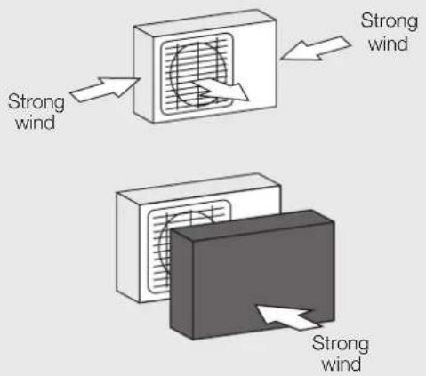
text_image
Strong wind Strong wind Strong windIf the unit is frequently exposed to heavy rain or snow:
Build a shelter above the unit to protect it from the rain or snow. Be careful not to obstruct air flow around the unit.
Step 2: Install drain joint (heat pump unit only)
Before bolting the outdoor unit in place, you must install the drain joint at the bottom of the unit. Note that there are two different types of drain joints depending on the type of outdoor unit.
If the drain joint comes with a rubber seal (see Fig. A), do the following:
- Fit the rubber seal on the end of the drain joint that will connect to the outdoor unit.
- Insert the drain joint into the hole in the base pan of the unit.
- Rotate the drain joint 90° until it clicks in place facing the front of the unit.
- Connect a drain hose extension (not included) to the drain joint to redirect water from the unit during heating mode.
If the drain joint doesn't come with a rubber seal (see Fig. B), do the following:
-
Insert the drain joint into the hole in the base pan of the unit. The drain joint will click in place.
-
Connect a drain hose extension (not included) to the drain joint to redirect water from the unit during heating mode.

text_image
Base pan hole of outdoor unit Seal Seal Drain joint A B
IN COLD CLIMATES
In cold climates, make sure that the drain hose is as vertical as possible to ensure swift water drainage. If water drains too slowly, it can freeze in the hose and flood the unit.
Step 3: Anchor outdoor unit
The outdoor unit can be anchored to the ground or to a wall-mounted bracket with a bolt (M10). Prepare the installation base of the unit according to the dimensions below.
Unit mounting dimensions
The following is a list of different outdoor unit sizes and the distance between their mounting feet. Prepare the installation base of the unit according to the dimensions below.
Outdoor unit types and specifications
Split type outdoor unit
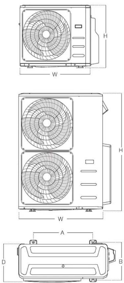
| Outdoor unit dimensionsW x H x D | Mounting dimensions | |
| Distance A | Distance B | |
| 946mm x 810mm x 410mm 673mm 403mm | ||
| 952mm x 1333mm x 415mm 634mm 404mm | ||
Rows of series installation
The relations between H, A and L are as follows.
| L | A | |
| L ≤ HL ≤ 1/2H | 250mm or more | |
| 1/2H < L ≤ H | 300mm or more | |
| L >H Cannot be installed | ||
Notes on drilling hole in wall
You must drill a hole in the wall for the refrigerant piping, and the signal cable that will connect the indoor and outdoor units.
- Determine the location of the wall hole based on the location of the outdoor unit.
- Using a 65mm core drill, drill a hole in the wall. NOTE: When drilling the wall hole, make sure to avoid wires, plumbing, and other sensitive components.
Place the protective wall cuff in the hole. This protects the edges of the hole and helps seal it when you finish the installation process.
When selecting a KS09 indoor unit
The KS09 indoor unit can only be connected with an A system. If there are two KS09 indoor units, they can be connected with A and B systems.
Connective pipe size of an A and B system (unit: inch)
| Indoor unit capacity (kW) | Liquid Gas | |
| KSI09/KSI12 1/4 3/8 | ||
| KSI12/KSI18 1/4 1/2 | ||
| KSI24 3/8 5/8 |
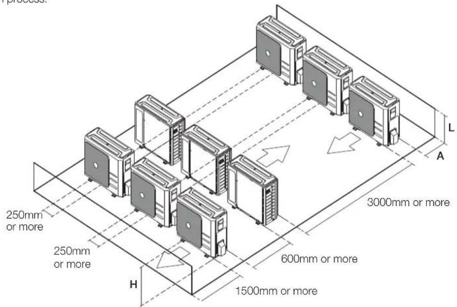
text_image
250mm or more 250mm or more H 1500mm or more 600mm or more 3000mm or more A L5. KM refrigerant piping connection

natural_image
Technical illustration of a mechanical assembly showing two stages of fastening or threading process (no text or symbols)Note on pipe length
The length of refrigerant piping will affect the performance and energy efficiency of the unit. Nominal efficiency is tested on units with a pipe length of 5000mm.
Refer to the table below for specifications on the maximum length and drop height of piping.
Maximum length and drop height of refrigerant piping per unit model
| Model Capacity (kW) Min. length (mm) Max. length (mm) | Max. height difference (mm) | |||
| KSI06 2.0 3000 2500 1000 | ||||
| KSI09 2.6 3000 2500 1000 | ||||
| KSI12 3.5 3000 2500 1000 | ||||
| KSI18 5.0 3000 3000 2000 | ||||
| KSI24 7.0 3000 5000 2500 | ||||
| KSI28 8.0 3000 5000 2500 | ||||
| KMD09 2.5 3000 2500 1000 | ||||
| KMD12 3.5 3000 2500 1000 | ||||
| KMD18 5.2 3000 3000 2000 | ||||
| KMD24 7.0 3000 3000 2000 | ||||
| KMC09 2.6 3000 2500 1000 | ||||
| KMC12 3.5 3000 2500 1000 | ||||
| KMC18 5.3 3000 3000 2000 | ||||
For KMD and KMC models

AUTION
- Oil traps
If the indoor unit is installed higher than the outdoor unit:
If oil flows back into the outdoor unit's compressor, this might cause liquid compression or deterioration of oil return. Oil traps in the rising gas piping can prevent this.
An oil trap should be installed every 10000mm of vertical suction line riser.

AUTION
If the outdoor unit is installed higher than the indoor unit:
It is recommended that vertical suction risers not be up-sized. Proper oil return to the compressor should be maintained with suction gas velocity. If velocities drop below 7.62m/s, oil return will be decreased. An oil trap should be installed every 6000mm of vertical suction line riser.
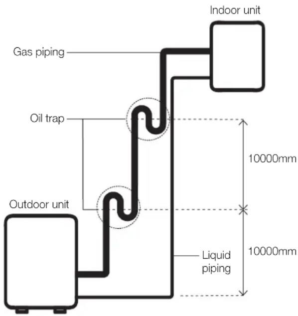
text_image
Gas piping Oil trap Outdoor unit Indoor unit 10000mm Liquid piping 10000mmThe indoor unit is installed higher than the indoor unit
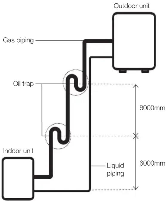
text_image
Outdoor unit Gas piping Oil trap Indoor unit Liquid piping 6000mm 6000mmThe outdoor unit is installed higher than the indoor unit
Connection instructions – refrigerant piping

CAUTION
- The branching pipe must be installed horizontally. An angle of more than 10^ may cause malfunction.
- Do not install the connecting pipe until both indoor and outdoor units have been installed.
• Insulate both the gas and liquid piping to prevent water leakage.
Step 1: Cut pipes
When preparing refrigerant pipes, take extra care to cut and flare them properly. This will ensure efficient operation and minimise the need for future maintenance.
- Measure the distance between the indoor and outdoor units.
- Using a pipe cutter, cut the pipe a little longer than the measured distance.
- Make sure that the pipe is cut at a perfect 90^ angle.
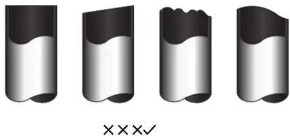
natural_image
Four identical 3D-rendered cylindrical objects with wavy surfaces, no text or symbols present90° Oblique Rough Warped

DO NOT DEFORM PIPE WHILE CUTTING
Be extra careful not to damage, dent, or deform the pipe while cutting. This will drastically reduce the heating efficiency of the unit.
Step 2: Remove burrs
- Burrs can affect the air-tight seal of refrigerant piping connection. They must be completely removed.
- Hold the pipe at a downward angle to prevent burrs from falling into the pipe.
- Using a reamer or deburring tool, remove all burrs from the cut section of the pipe.

text_image
Point down Pipe DeburrerStep 3: Flare pipe ends
Proper flaring is essential to achieve an airtight seal.
- After removing burrs from cut pipe, seal the ends with PVC tape to prevent foreign materials from entering the pipe.
- Sheath the pipe with insulating material.
- Place flare nuts on both ends of pipe. Make sure they are facing in the right direction, because you can't put them on or change their direction after flaring.

text_image
Flare nut Copper pipe-
Remove PVC tape from ends of pipe when ready to perform flaring work.
-
Clamp flare form on the end of the pipe. The end of the pipe must extend beyond the flare form.

text_image
Flare form Pipe-
Place flaring tool onto the form.
-
Turn the handle of the flaring tool clockwise until the pipe is fully flared. Flare the pipe in accordance with the dimensions.
Piping extension beyond flare form
| Pipe gauge | Tightening torque Flare dimension (A) (Unit: mm) | |
| Min. Max. | ||
| ∅ 6.35 18 – 20 N.m(183 – 204 kgf.cm) | 8.4 8.7 | |
| ∅ 9.52 25 – 26 N.m(255 – 265 kgf.cm) | 13.2 13.5 | |
| ∅ 12.7 35 – 36 N.m(357 – 367 kgf.cm) | 16.2 16.5 | |
| ∅ 16 45 – 47 N.m(459 – 480 kgf.cm) | 19.2 19.7 | |
| ∅ 19 65 – 67 N.m(663 – 683 kgf.cm) | 23.2 23.7 | |
| ∅ 22 75 – 85 N.m(765 – 867 kgf.cm) | 26.4 26.9 | |
Flare shape
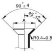
- Remove the flaring tool and flare form, then inspect the end of the pipe for cracks and even flaring.
Step 4: Connect pipes
Connect the copper pipes to the indoor unit first, then connect it to the outdoor unit. You should first connect the low-pressure pipe, then the high-pressure pipe.
-
When connecting the flare nuts, apply a thin coat of refrigeration oil to the flared ends of the pipes.
-
Align the centre of the two pipes that you will connect.
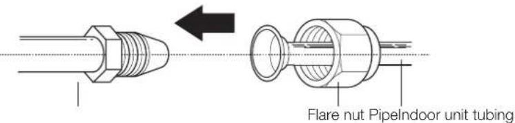
text_image
Flare nut PipelIndoor unit tubing-
Tighten the flare nut as tightly as possible by hand.
-
Using a spanner, grip the nut on the unit tubing.
-
While firmly gripping the nut, use a torque wrench to tighten the flare nut according to the torque values in above table.
NOTE: Use both a spanner and a torque wrench when connecting or disconnecting pipes to/from the unit.
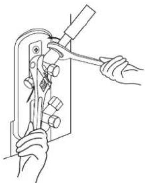
natural_image
Line drawing of hands using a tool to adjust or install a mechanical component (no text or symbols present)CAUTION
- Ensure that you wrap insulation around the piping. Direct contact with the bare piping may result in burns or frostbite.
- Make sure the pipe is properly connected. Over-tightening may damage the bell mouth and undertightening may lead to leakage.
Note on minimum bend radius
Carefully bend the tubing in the middle according to the diagram below. Do not bend the tubing more than 90^ or more than 3 times.
Bend the pipe with thumb

natural_image
Line drawing of two hands stretching a curved object (no text or symbols)Min radius 100mm
- After connecting the copper pipes to the indoor unit, wrap the power cable, signal cable and the piping together with binding tape.
NOTE: Do not intertwine signal cable with other wires. While bundling these items together, do not intertwine or cross the signal cable with any other wiring.
- Thread this pipeline through the wall and connect it to the outdoor unit.
- Insulate all the piping, including the valves of the outdoor unit.

CAUTION
Check to make sure there is no refrigerant leak after completing the installation work. If there is a refrigerant leak, locate and repair the leak before evacuating the system (refer to the Leak Testing and Evacuation section of this manual).
6. KM wiring
BEFORE PERFORMING ANY ELECTRICAL WORK, READ THESE REGULATIONS
- All wiring must comply with local and national electrical codes, regulations and must be installed by a licensed electrician.
- All electrical connections must be made according to the Electrical Connection Diagram located on the panels of the indoor and outdoor units.
- If there is a serious safety issue with the power supply, stop work immediately. Explain your reasoning to the client, and refuse to install the unit until the safety issue is properly resolved.
- Power voltage should be within 90 - 110% of rated voltage. Insufficient power supply can cause malfunction, electrical shock, or fire.
- If connecting power to fixed wiring, install a surge protector and main power switch with a capacity of 1.5 times the maximum current of the unit.
- If connecting power to fixed wiring, a switch or circuit breaker that disconnects all poles and has a contact separation of at least 3mm must be incorporated in the fixed wiring. The qualified technician must use an approved circuit breaker or switch.
- Only connect the unit to an individual branch circuit outlet. Do not connect another appliance to that outlet.
-
Make sure to properly ground the air conditioner.
-
Every wire must be firmly connected. Loose wiring can cause the terminal to overheat, resulting in product malfunction and possible fire.
- Do not let wires touch or rest against refrigerant tubing, the compressor, or any moving parts within the unit.
- If the unit has an auxiliary electric heater, it must be installed at least 1000mm away from any combustible materials.
- To avoid getting an electric shock, never touch the electrical components soon after the power supply has been turned off. After turning off the power, always wait 10 minutes or more before you touch the electrical components.
- Make sure that you do not cross your electrical wiring with your signal wiring. This may cause distortion and interference.
- The unit must be connected to the main outlet. Normally, the power supply must have a impedance of 32 ohms.
- No other equipment should be connected to the same power circuit.
- Connect the outdoor wires before connecting the indoor wires.
WARNING
BEFORE PERFORMING ANY ELECTRICAL OR WIRING WORK, TURN OFF THE MAIN POWER TO THE SYSTEM.
Note on isolator
An isolator and leakage protection switch with protective device must be used (purchased separately).
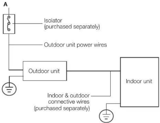
flowchart
graph TD
    A["Indoor unit"] --> B["Outdoor unit"]
    B --> C["Isolator (purchased separately)"]
    B --> D["Outdoor unit power wires"]
    B --> E["Indoor & outdoor connective wires (purchased separately)"]
Circuit breaker recommendations
| Model KM24 KM28 | KM46 | |||
| Power Phase 1 Phase 1 Phase 1 Phase | ||||
| Volt 208-240V 208-240V 208-240V | ||||
| Circuit breaker (A) 25 | 25 | 32 | ||
Outdoor unit wiring

WARNING
Before performing any electrical or wiring work, turn off the main power to the system.
Electrical requirement
The indoor unit is powered by the outdoor unit. Do not power indoor unit from separate power source.

WARNING
Standard for electrical wiring and equipment differs in each country or region. Before you start electrical working, confirm related regulations, codes or standards.
| Cable Conductor size (mm2) | Type Remarks | ||
| Power cable | 2.5 Type | 60245 IEC 57 | 2 core + Earth (Ground)1 ∅ 230 V |
| Cable Conductor size (mm2) | Type Remarks | ||
| Interconnect power cable | 1.5 Type | 60245IEC 57 | 2 core + Earth(Ground)1 ∅ 230 V |
| Cable Conductor size (mm2) | Type Remarks | ||
| Signal cable | 1.0 Type | 60245 IEC 57 | 2 core Shielded |
Cable length: Limit voltage drop to less than 2%.
Increase cable gauge if voltage drop is 2% or more.
If the interconnect cable exceeds 30M in length 2.5mm thick cable should be used.
The cable specifications are based on the assumption that a metal or plastic conduit is used with no more than three cables contained in a conduit and a voltage drop of 2%.
Preparing cable
-
Selecting cable: Select the power source cable and connecting cable in accordance with the specifications mentioned below: 3-core Power source cable* or more 2.5mm^2 or more, conformed with 60245 IEC57. When selecting the power source cable length, make sure that voltage drop is less than 2% . If the wire length gets longer, increase the wire diameter.
Connecting cable: 3-core* 1.5mm², conformed with 60245 IEC57. -
Arrange each wire length as shown. Make sure that each wire is stripped 10mm from the end.
-
Attach round crimp-type terminal to each wire as shown. Select the size of round crimp-type terminal after considering the specifications of terminal block and wire diameter.
Power and interconnect cable

text_image
30mm or more Earth wire 40mm or moreSignal cable
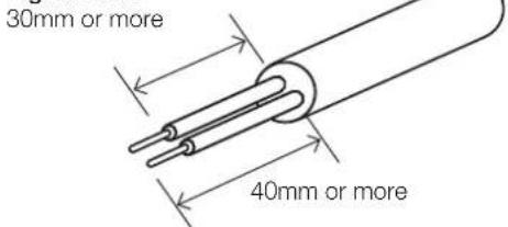
text_image
30mm or more 40mm or moreWire end
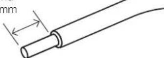
natural_image
Diagram of a cylindrical cable with a gap labeled 'mm' (no text or symbols beyond the label)Round crimp type

text_image
terminal SleeveOutdoor unit wiring

WARNING Before performing any electrical or wiring work, turn off the main power to the system.
- Prepare the cable for connection
a. You must first choose the right cable size. Be sure to use H07RN-F cables.
b. Using wire strippers, strip the rubber jacket from both ends of the signal cable to reveal approximately 15cm of wire.
c. Strip the insulation from the ends.
d. Using a wire crimper, crimp u-lugs on the ends.
NOTE: When connecting the wires, strictly follow the wiring diagram found inside the electrical box cover.
- Remove the electric cover of the outdoor unit. If there is no cover on the outdoor unit, take off the bolts from the maintenance board and remove the protection board.
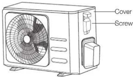
text_image
Cover Screw- Connect the u-lugs to the terminals. Match the wire colours/labels with the labels on the terminal block. Firmly screw the u-lug of each wire to its corresponding terminal.
- Clamp down the cable with the cable clamp.
- Insulate unused wires with electrical tape. Keep them away from any electrical or metal parts.
- Reinstall the cover of the electric control box.
Harmonic declaration
"The equipment M4OB-36HFN8-Q complies with IEC 61000-3-12 provided that the short-circuit power Ssc is greater than or equal to 4787737.5 at the interface point between the user's supply and the public system. It is the responsibility of the installer or user of the equipment to ensure, by consultation with the distribution network operator if necessary, that the equipment is connected only to a supply with a short-circuit power Ssc greater than or equal to 4787737.5."
"The equipment M5OD-42HFN8-Q complies with IEC 61000-3-12 provided that the short-circuit power Ssc is greater than or equal to 3190042.5 at the interface point between the user's supply and the public system. It is the responsibility of the installer or user of the equipment to ensure, by consultation with the distribution network operator if necessary, that the equipment is connected only to a supply with a short-circuit power Ssc greater than or equal to 3190042.5."
Wiring figure
CAUTION
Connect the connective cables to the terminals, as identified, with their matching numbers on the terminal block of the indoor and outdoor units. For example, in the US models shown in the following diagram, Terminal L1(A) of the outdoor unit must connect with terminal L1 on the indoor unit.

flowchart
graph TD
    A["L1 L2 L1"] -->|Power| B["To A To B"]
    C["S (A)"] -->|Switch| B
    D["S (B)"] -->|Switch| B
    E["L1 (B)"] -->|Switch| B
    F["L2 (B)"] -->|Switch| B
    G["S (B)"] -->|Switch| B
    H["Power"] --> I["To A To B"]
    style A fill:#f9f,stroke:#333
    style C fill:#f9f,stroke:#333
    style D fill:#f9f,stroke:#333
    style E fill:#f9f,stroke:#333
    style F fill:#f9f,stroke:#333
    style G fill:#f9f,stroke:#333
    style H fill:#ccf,stroke:#333
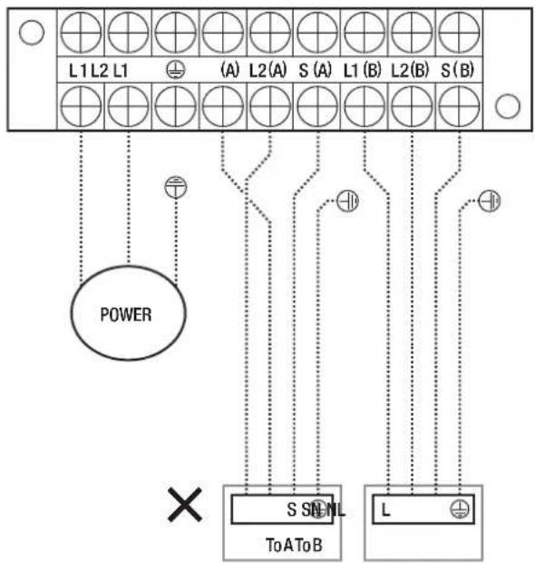
flowchart
graph TD
    A["L1 L2 L1"] -->|Power| B["To A"]
    C["(A) L2(A) S (A) L1(B) L2(B) S (B)"] -->|Signal| D["S SNL To A To B"]
    E["L"] -->|Signal| F["To A"]
    G["×"] --> H["Power"]
    I["○"] --> J["Power"]
NOTE: Refer to the following figures.
Run the main power cord through the lower line-outlet of the cord clamp.
- - - - This symbol indicates field wiring.

NOTE: Use the magnetic ring to hitch the connective cable of indoor and outdoor units after installation. One magnetic ring is used for one cable.
One-two models
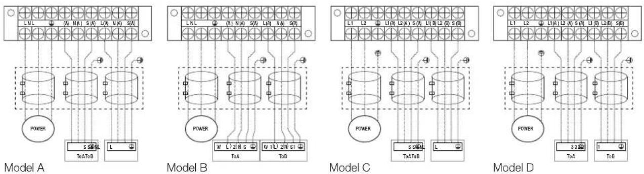
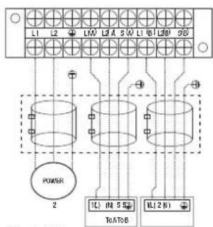
text_image
L1 L2 L3 A S (A) L1 L2 L3 D SG POWER 2 TC (M) 5 SQ TcATbB DL (2 N)Model E
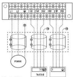
text_image
L1 L2 1 Q 2 Q 3 Q 1 Q8 2 Q 3 Q0 POWER 320Ω ToAToB 1Model F
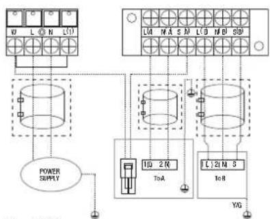
text_image
V1 L O N L01 L04 N A S M L0 B M D S01 POWER SUPPLY 10 2 R ToA C.21 M S ToR YGModel G

flowchart
graph TD
    A["POWER SUPPLY"] --> B["Transformer 1"]
    A --> C["Transformer 2"]
    A --> D["Terminal Block 1"]
    B --> E["Terminal Block 2"]
    C --> F["Terminal Block 3"]
    D --> G["Terminal Block 4"]
    E --> H["Power Supply"]
    F --> I["Power Supply"]
    G --> J["Power Supply"]
Model H

flowchart
graph TD
    A["ToA"] --> B["POWER SUPPLY"]
    B --> C["ToB"]
    C --> D["ToC"]
    D --> E["Load"]
    style A fill:#f9f,stroke:#333
    style B fill:#ccf,stroke:#333
    style C fill:#cfc,stroke:#333
    style D fill:#fcc,stroke:#333
Model I

flowchart
graph TD
    A["Grid Grid"] --> B["Power Supply"]
    A --> C["ToB"]
    A --> D["ToA"]
    B --> E["L N S ⊕"]
    D --> F["L N S ⊕"]
    style A fill:#f9f,stroke:#333
    style B fill:#ccf,stroke:#333
    style C fill:#cfc,stroke:#333
    style D fill:#fcc,stroke:#333
Model J

flowchart
graph TD
    A["POWER SUPPLY"] --> B["TOATOS"]
    C["S01"] --> D["Grid"]
    E["S02"] --> F["Grid"]
    G["S1"] --> H["Grid"]
    I["S2"] --> J["Grid"]
    K["NWLI"] --> L["Toats"]
    M["NM S"] --> N["Toats"]
    O["NM"] --> P["Toats"]
    Q["LW"] --> R["Toats"]
    S["L"] --> T["Grid"]
    U["L"] --> V["Grid"]
    W["L"] --> X["Grid"]
    Y["L"] --> Z["Grid"]
Model K

flowchart
graph TD
    A["Power Supply"] --> B["L(A)"]
    A --> C["L(B)"]
    D["Terminal Block L(A)"] --> E["L(A)"]
    F["Terminal Block L(B)"] --> G["L(B)"]
    H["Terminal Block L(B)"] --> I["L(B)"]
    J["Terminal Block L(B)"] --> K["L(B)"]
    L["Terminal Block L(B)"] --> M["L(B)"]
    N["Terminal Block L(B)"] --> O["L(B)"]
    P["Terminal Block L(B)"] --> Q["L(B)"]
    R["Terminal Block L(B)"] --> S["L(B)"]
    T["Terminal Block L(B)"] --> U["L(B)"]
    V["Terminal Block L(B)"] --> W["L(B)"]
    X["Terminal Block L(B)"] --> Y["L(B)"]
    Z["Terminal Block L(B)"] --> AA["L(B)"]
    AB["Terminal Block L(B)"] --> AC["L(B)"]
    AD["Terminal Block L(B)"] --> AE["L(B)"]
    AF["Terminal Block L(B)"] --> AG["L(B)"]
    AH["Terminal Block L(B)"] --> AI["L(B)"]
    AJ["Terminal Block L(B)"] --> AK["L(B)"]
    AL["Terminal Block L(B)"] --> AM["L(B)"]
    AN["Terminal Block L(B)"] --> AO["L(B)"]
    AP["Terminal Block L(B)"] --> AQ["L(B)"]
    AR["Terminal Block L(B)"] --> AS["L(B)"]
    AT["Terminal Block L(B)"] --> AU["L(B)"]
    AV["Terminal Block L(B)"] --> AW["L(B)"]
    AX["Terminal Block L(B)"] --> AY["L(B)"]
    AZ["Terminal Block L(B)"] --> BA["L(B)"]
    BB["Terminal Block L(B)"] --> BC["L(B)"]
    BD["Terminal Block L(B)"] --> BE["L(B)"]
    BF["Terminal Block L(B)"] --> BG["L(B)"]
    BH["Terminal Block L(B)"] --> BI["L(B)"]
    BJ["Terminal Block L(B)"] --> BK["L(B)"]
    BL["Terminal Block L(B)"] --> BM["L(B)"]
    BN["Terminal Block L(B)"] --> BO["L(B)"]
    BP["Terminal Block L(B)"] --> BQ["L(B)"]
    BR["Terminal Block L(B)"] --> BS["L(B)"]
    BT["Terminal Block L(B)"] --> BU["L(B)"]
    BV["Terminal Block L(B)"] --> BW["L(B)"]
    BX["Terminal Block L(B)"] --> BY["L(B)"]
    BZ["Terminal Block L(B)"] --> CA["L(B)"]
    CB["Terminal Block L(B)"] --> CBL["L(B)"]
    CC["Terminal Block L(B)"] --> CD["L(B)"]
    CE["Terminal Block L(B)"] --> CF["L(B)"]
    GD["Terminal Block L(B)"] --> GDY["L(B)"]
    DG["Terminal Block L(B)"] --> DH["L(B)"]
    DI["Terminal Block L(B)"] --> DJ["L(B)"]
    DK["Terminal Block L(B)"] --> DL["L(B)"]
    DV["Terminal Block L(B)"] --> DVY["L(B)"]
    DW["Terminal Block L(B)"] --> DWY["L(B)"]
    DX["Terminal Block L(B)"] --> DXY["L(B)"]
    DXZ["Terminal Block L(B)"] --> DXZL["L(B)"]
    DXY --> DXZY["L(B)"]
    DXZ --> DXZYL["L(B)"]
    DXZ --> DXZYX["L(B)"]
    DXZ --> DXZYXY["L(B)"]
    DXZ --> DXZYXZL["L(B)"]
    DXZ --> DXZYXZD["L(B)"]
    DXZ --> DXZYXZDXZL["X"]
Model L
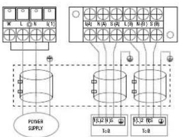
flowchart
graph TD
    A["Power Supply"] --> B["Grid 1"]
    A --> C["Grid 2"]
    B --> D["Output 1"]
    B --> E["Output 2"]
    C --> F["Output 3"]
    C --> G["Output 4"]
    D --> H["Output 5"]
    E --> I["Output 6"]
    F --> J["Output 7"]
    G --> K["Output 8"]
Model M
One-three models
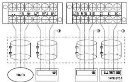
text_image
LL NN L/A N/A1 S/A1 L/L W N/D S/B C1 C1 SC POWER LLL NNN S/B To CTo BT-AModel A
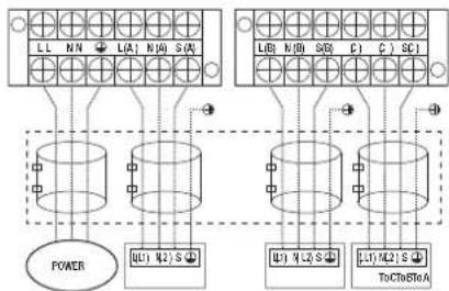
flowchart
graph TD
    A["Power"] --> B["L1"]
    A --> C["L2"]
    A --> D["S"]
    B --> E["ToCtoSRA"]
    C --> F["ToCtoSRA"]
    D --> G["ToCtoSRA"]
    H["LL N/N L(A) N/A S(A)"] --> I["Power"]
    J["UB1 N2 S"] --> K["ToCtoSRA"]
    L["UB1 N/L S"] --> M["ToCtoSRA"]
Model B
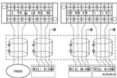
flowchart
graph TD
    subgraph Power
        A["Power"] --> B["M2L N1S"]
        B --> C["L1 N1 S"]
        C --> D["M2 L N1 S"]
        D --> E["W2L W1S"]
        E --> F["TnCln R1A"]
    end
    subgraph Bottom
        G["Bottom Panel"] --> H["L1 N1 S"]
        H --> I["L1 N1 S"]
        I --> J["M2 L N1 S"]
        J --> K["W2L W1S"]
        K --> L["TnCln R1A"]
    end
Model C
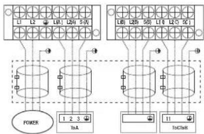
flowchart
graph TD
    A["Power"] --> B["1"]
    A --> C["2"]
    A --> D["3"]
    E["InA"] --> F["1"]
    E --> G["2"]
    E --> H["3"]
    I["InC"] --> J["11"]
    I --> K["2"]
    I --> L["3"]
Model D
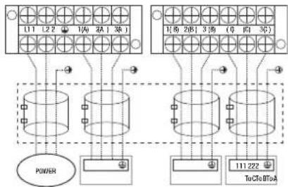
flowchart
graph TD
    A["Power"] --> B["11"]
    A --> C["2"]
    A --> D["3"]
    A --> E["4"]
    A --> F["5"]
    A --> G["6"]
    A --> H["7"]
    A --> I["8"]
    A --> J["9"]
    A --> K["10"]
    A --> L["11 222"]
    M["TuCfa BToA"] --> N["11 222"]
    O["11 222"] --> P["3"]
    Q["3"] --> R["6"]
    S["6"] --> T["9"]
    U["9"] --> V["10"]
Model E
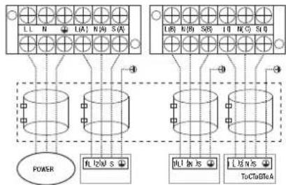
flowchart
graph TD
    A["Power"] --> B["TL1N/S"]
    B --> C["TL1N/S"]
    C --> D["TL1N/S"]
    D --> E["ToClo/TA"]
    F["Terminal Block 1"] --> G["TL1N/S"]
    H["Terminal Block 2"] --> I["TL1N/S"]
    J["Terminal Block 3"] --> K["TL1N/S"]
    L["Terminal Block 4"] --> M["TL1N/S"]
    N["Terminal Block 5"] --> O["TL1N/S"]
    P["Terminal Block 6"] --> Q["TL1N/S"]
    R["Terminal Block 7"] --> S["TL1N/S"]
    T["Terminal Block 8"] --> U["TL1N/S"]
    V["Terminal Block 9"] --> W["TL1N/S"]
    X["Terminal Block 10"] --> Y["TL1N/S"]
Model F
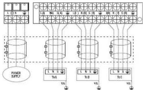
flowchart
graph TD
    A["Power Supply"] --> B["L A"]
    A --> C["L B"]
    A --> D["L C"]
    B --> E["ToA"]
    C --> F["ToB"]
    D --> G["ToC"]
    E --> H["YAG"]
    F --> I["YAG"]
    G --> J["YAG"]
Model G
One-four models
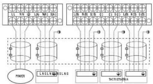
text_image
LL NN LA NA SA L0 N8 S0 C1 C2 SC L0 N0 S0 POWER LNSLN NSLNS ToC TO DTo AModel A

flowchart
graph TD
    subgraph_BusBar1["Busbar 1"]
        L1["L1"] --> N1["N1"]
        L2["L2"] --> N2["N2"]
        L3["L3"] --> N3["N3"]
        L4["L4"] --> N4["N4"]
        L5["L5"] --> N5["N5"]
        L6["L6"] --> N6["N6"]
        L7["L7"] --> N7["N7"]
        L8["L8"] --> N8["N8"]
        L9["L9"] --> N9["N9"]
        L10["L10"] --> N10["N10"]
        L11["L11"] --> N11["N11"]
        L12["L12"] --> N12["N12"]
        L13["L13"] --> N13["N13"]
        L14["L14"] --> N14["N14"]
        L15["L15"] --> N15["N15"]
        L16["L16"] --> N16["N16"]
        L17["L17"] --> N17["N17"]
        L18["L18"] --> N18["N18"]
        L19["L19"] --> N19["N19"]
        L20["L20"] --> N20["N20"]
        L21["L21"] --> N21["N21"]
        L22["L22"] --> N22["N22"]
        L23["L23"] --> N23["N23"]
        L24["L24"] --> N24["N24"]
        L25["L25"] --> N25["N25"]
        L26["L26"] --> N26["N26"]
        L27["L27"] --> N27["N27"]
        L28["L28"] --> N28["N28"]
        L29["L29"] --> N29["N29"]
        L30["L30"] --> N30["N30"]
        L31["L31"] --> N31["N31"]
        L32["L32"] --> N32["N32"]
        L33["L33"] --> N33["N33"]
        L34["L34"] --> N34["N34"]
        L35["L35"] --> N35["N35"]
        L36["L36"] --> N36["N36"]
        L37["L37"] --> N37["N37"]
        L38["L38"] --> N38["N38"]
        L39["L39"] --> N39["N39"]
        L40["L40"] --> N40["N40"]
        L41["L41"] --> N41["N41"]
        L42["L42"] --> N42["N42"]
        L43["L43"] --> N43["N43"]
        L44["L44"] --> N44["N44"]
        L45["L45"] --> N45["N45"]
        L46["L46"] --> N46["N46"]
        L47["L47"] --> N47["N47"]
        L48["L48"] --> N48["N48"]
        L49["L49"] --> N49["N49"]
        L50["L50"] --> N50["N50"]
        L51["L51"] --> N51["N51"]
        L52["L52"] --> N52["N52"]
        L53["L53"] --> N53["N53"]
        L54["L54"] --> N54["N54"]
        L55["L55"] --> N55["N55"]
        L56["L56"] --> N56["N56"]
        L57["L57"] --> N57["N57"]
        L58["L58"] --> N58["N58"]
        L59["L59"] --> N59["N59"]
        L60["L60"] --> N60["N60"]
        L61["L61"] --> N61["N61"]
        L62["L62"] --> N62["N62"]
        L63["L63"] --> N63["N63"]
        L64["L64"] --> N64["N64"]
        L65["L65"] --> N65["N65"]
        L66["L66"] --> N66["N66"]
        L67["L67"] --> N67["N67"]
        L68["L68"] --> N68["N68"]
        L69["L69"] --> N69["N69"]
        L70["L70"] --> N70["N70"]
        L71["L71"] --> N71["N71"]
        L72["L72"] --> N72["N72"]
        L73["L73"] --> N73["N73"]
        L74["L74"] --> N74["N74"]
        L75["L75"] --> N75["N75"]
        L76["L76"] --> N76["N76"]
        L77["L77"] --> N77["N77"]
        L78["L78"] --> N78["N78"]
        L79["L79"] --> N79["N79"]
        L80["L80"] --> N80["N80"]
Model B

text_image
LL NN LW MA1 SAD LW N/B S/D T/C I/O S/O L/D N/D S/D POWER W2L H S/D W2L H S/D W2L H S/D InClDInS/AModel C

text_image
L1 L2 1W 2H 3W 10 20 30 POWER 123 InA 123 InB 123 ToC 123 ToDModel D
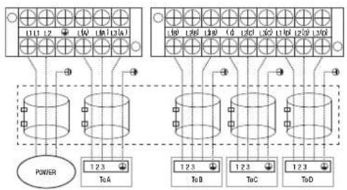
text_image
111 12 10 130 140 10 120 130 C D 120 130 140 10 120 130 C D 120 130 140 POWER 12.3 ToA 12.3 ToD 12.3 ToC 12.3 ToDModel E
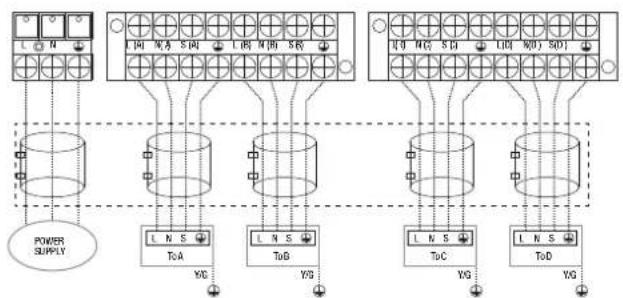
flowchart
graph TD
    A["POWER SUPPLY"] --> B["T0A"]
    A --> C["T0B"]
    A --> D["T0C"]
    A --> E["T0D"]
    B --> F["YG"]
    C --> G["YG"]
    D --> H["YG"]
    E --> I["YG"]
    F --> J["L N S"]
    G --> K["L N S"]
    H --> L["L N S"]
    I --> M["L N S"]
Model F
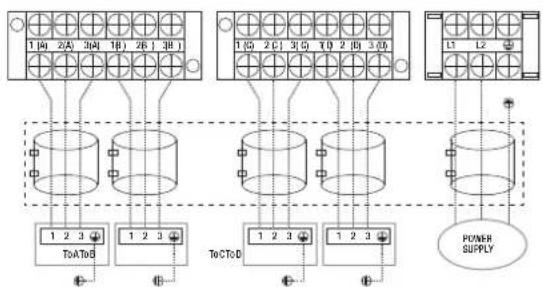
flowchart
graph TD
    A["Power Supply"] --> B["ToA/D"]
    A --> C["ToC/D"]
    A --> D["12-13 Bus"]
    B --> E["1 2 3"]
    C --> F["1 2 3"]
    D --> G["12-13 Bus"]
    style A fill:#f9f,stroke:#333
    style B fill:#ccf,stroke:#333
    style C fill:#ccf,stroke:#333
    style D fill:#ccf,stroke:#333
Model G
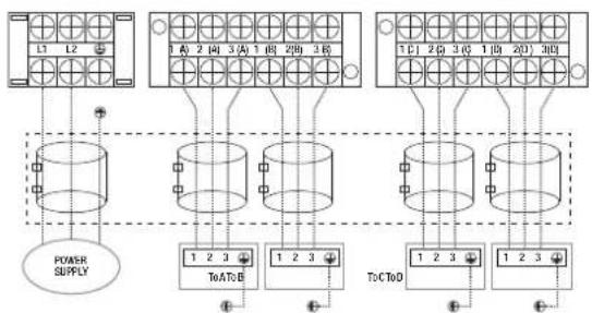
flowchart
graph TD
    A["POWER SUPPLY"] --> B["1 2 3"]
    B --> C["ToA:0"]
    C --> D["1 2 3"]
    D --> E["Tc:CToD"]
    E --> F["1 2 3"]
    F --> G["1 2 3"]
    G --> H["Tc:CToD"]
    H --> I["1 2 3"]
    I --> J["1 2 3"]
    J --> K["Tc:CToD"]
    K --> L["1 2 3"]
    L --> M["Tc:CToD"]
    M --> N["1 2 3"]
    N --> O["Tc:CToD"]
    O --> P["1 2 3"]
    P --> Q["Tc:CToD"]
    Q --> R["1 2 3"]
    R --> S["Tc:CToD"]
    S --> T["1 2 3"]
    T --> U["Tc:CToD"]
    U --> V["1 2 3"]
    V --> W["Tc:CToD"]
    W --> X["1 2 3"]
    X --> Y["Tc:CToD"]
    Y --> Z["1 2 3"]
    Z --> AA["Tc:CToD"]
Model H
One-five models
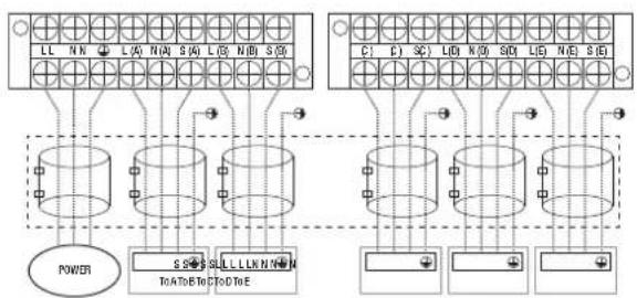
flowchart
graph TD
    subgraph Power
        A["Power"] --> B["Component Block"]
        B --> C["Component Block"]
        C --> D["Component Block"]
        D --> E["Component Block"]
    end
    subgraph Control
        F["Control Block"] --> G["Component Block"]
        G --> H["Component Block"]
        H --> I["Component Block"]
        I --> J["Component Block"]
    end
Model A

flowchart
graph TD
    subgraph Power
        A["Power Input"] --> B["TOA"]
        C["TOA"] --> D["TOB"]
    end
    subgraph Circuit
        E["TOA"] --> F["TOB"]
        G["TOB"] --> H["TOC"]
        I["TOC"] --> J["TOE"]
    end
    subgraph Control
        K["Control Input"] --> L["TOA"]
        M["Control"] --> N["TOB"]
        O["Control"] --> P["TOC"]
        Q["Control"] --> R["TOE"]
    end
    style Power fill:#f9f,stroke:#333
    style Circuit fill:#ccf,stroke:#333
Model B
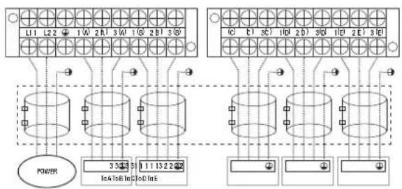
text_image
L1 L2 1 W 2 B 3 W 1 G 2 B 3 IC C1 OC 1B 2 D 3D 1D ZE 3E POWER 33435 111322 Ia4 Ib8 In3 Ia0 In5Model C

text_image
L1 L2 L3 L4 L5 L6 L7 L8 L9 L10 L11 L12 L13 L14 L15 L16 L17 L18 L19 L20 L21 POWER 3 3 3 3 3 3 3 3 3 3 3 3 3 3 3 3 3 3 3 3 InA to B Ind InB IndModel D
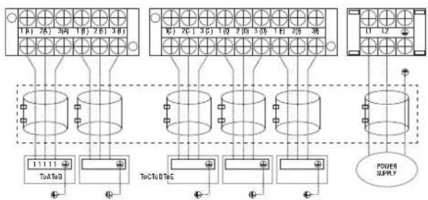
flowchart
graph TD
    A["Terminal Block 1"] --> B["ToA to D"]
    C["Terminal Block 2"] --> D["ToC to D to E"]
    E["Terminal Block 3"] --> F["ToC to D to E"]
    G["Terminal Block 4"] --> H["ToC to D to E"]
    I["Terminal Block 5"] --> J["ToC to D to E"]
    K["Terminal Block 6"] --> L["ToC to D to E"]
    M["Terminal Block 7"] --> N["ToC to D to E"]
    O["Terminal Block 8"] --> P["ToC to D to E"]
    Q["Terminal Block 9"] --> R["ToC to D to E"]
    S["Terminal Block 10"] --> T["ToC to D to E"]
    U["Terminal Block 11"] --> V["ToC to D to E"]
    W["Terminal Block 12"] --> X["ToC to D to E"]
    Y["Power Supply"] --> Z["Ground"]
Model E

flowchart
graph TD
    A["Power Supply"] --> B["Three cylindrical breakers"]
    B --> C["ToT&ToC"]
    B --> D["ToD"]
    B --> E["ToE"]
    B --> F["ToE1&ToS"]
    B --> G["ToE2&ToS"]
    B --> H["ToE3&ToS"]
    B --> I["ToE4&ToS"]
    B --> J["ToE5&ToS"]
    B --> K["ToE6&ToS"]
    B --> L["ToE7&ToS"]
    B --> M["ToE8&ToS"]
    B --> N["ToE9&ToS"]
    B --> O["ToE10&ToS"]
    B --> P["ToE11&ToS"]
    B --> Q["ToE12&ToS"]
    B --> R["ToE13&ToS"]
    B --> S["ToE14&ToS"]
    B --> T["ToE15&ToS"]
    B --> U["ToE16&ToS"]
    B --> V["ToE17&ToS"]
    B --> W["ToE18&ToS"]
    B --> X["ToE19&ToS"]
    B --> Y["ToE20&ToS"]
    B --> Z["ToE21&ToS"]
    B --> AA["ToE22&ToS"]
    B --> AB["ToE23&ToS"]
    B --> AC["ToE24&ToS"]
    B --> AD["ToE25&ToS"]
    B --> AE["ToE26&ToS"]
    B --> AF["ToE27&ToS"]
    B --> AG["ToE28&ToS"]
    B --> AH["ToE29&ToS"]
    B --> AI["ToE30&ToS"]
    B --> AJ["ToE31&ToS"]
    B --> AK["ToE32&ToS"]
    B --> AL["ToE33&ToS"]
    B --> AM["ToE34&ToS"]
    B --> AN["ToE35&ToS"]
    B --> AO["ToE36&ToS"]
    B --> AP["ToE37&ToS"]
    B --> AQ["ToE38&ToS"]
    B --> AR["ToE39&ToS"]
    B --> AS["ToE40&ToS"]
    B --> AT["ToE41&ToS"]
    B --> AU["ToE42&ToS"]
    B --> AV["ToE43&ToS"]
    B --> AW["ToE44&ToS"]
    B --> AX["ToE45&ToS"]
    B --> AY["ToE46&ToS"]
    B --> AZ["ToE47&ToS"]
    B --> BA["ToE48&ToS"]
    B --> BB["ToE49&ToS"]
    B --> BC["ToE50&ToS"]
Model F

CAUTION
After confirmation of the above conditions, follow these guidelines when performing wiring:
- Always have an individual power circuit specifically for the air conditioner. Always follow the circuit diagram posted on the inside of the control cover.
- Screws fastening the wiring in the casing of electrical fittings may come loose during transportation. Because loose screws may cause wire burn-out, check that the screws are tightly fastened.
- Check the specifications for the power source.
- Confirm that electrical capacity is sufficient.
- Confirm that starting voltage is maintained at more than 90 percent of the rated voltage marked on the name plate.
- Confirm that the cable thickness is as specified in the power source specifications.
- Always install an earth leakage circuit breaker in wet or moist areas.
- The following can be caused by a drop in voltage: vibration of a magnetic switch, damaging the contact point, broken fuses, and disturbance of normal functioning.
- Disconnection from a power supply must be incorporated into the fixed wiring. It must have an air gap contact separation of at least 3mm in each active (phase) conductors.
- Before accessing terminals, all supply circuits must be disconnected.
NOTE: To satisfy the EMC compulsory regulations, which is required by the international standard CISPR 14-1:2005/A2:2011 in specific countries or districts, please make sure you apply the correct magnetic rings on your equipment according to the wiring diagram that adhere to the equipment. Please contact your distributor or installer to get further information and purchase magnetic rings.
7. KM leak testing and evacuation
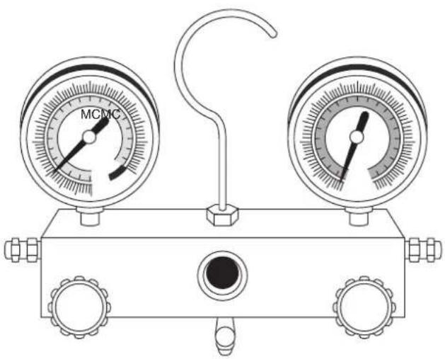
natural_image
Line drawing of a pressure gauge device with two gauges and a central hub (no text or symbols)Leak, pressure test and evacuation
The interconnecting pipe work and indoor unit must be pressure tested at 1000kpa and leak tested before being evacuated. Before using the manifold gauge and vacuum pump, read their operation manuals to familiarise yourself with how to use them properly.
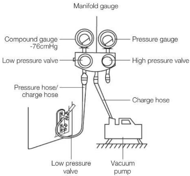
text_image
Manifold gauge Compound gauge -76cmHg Low pressure valve Pressure gauge High pressure valve Pressure hose/ charge hose Charge hose Low pressure valve Vacuum pump- Connect the charge hose of the manifold gauge to the outdoor unit's low pressure valve.
- Connect another charge hose from the manifold gauge to the pressure regulator of a nitrogen or Trace A Gas cylinder.
- Carefully add pressure 100kPa at a time to a maximum of 1000kPa and check for leaks in the interconnecting pipe work, connections, and indoor units. If a leak is found safely release the test pressure and repair leak before repeating step 3.
- Safely release the test pressure then connect charge hose to vacuum pump as shown in the diagram.
- Open the low pressure side of the manifold gauge. Keep the high pressure side closed.
- Turn on the vacuum pump to evacuate the system.
- Evacuate the interconnecting pipes to <=500 microns.
- Close the low pressure side of the manifold gauge, and turn off the vacuum pump.
- Wait for 5 minutes, then check that there has been no change in system vacuum.
- If the vacuum does not settle, repeat from Step 1 of Leak, pressure test and evacuation. If there is no change in system vacuum, unscrew the cap from the packed valve (high pressure valve).
Preparations and precautions
Air and foreign matter in the refrigerant circuit can cause abnormal rises in pressure, which can damage the air conditioner, reduce its efficiency, and cause injury. Use a vacuum pump and manifold gauge to evacuate the refrigerant circuit, removing any non-condensible gas and moisture from the system.
Evacuation should be performed upon initial installation and when unit is relocated.
Before performing evacuation
√ Check to make sure that both high pressure and low pressure pipes between the indoor and outdoor units are connected properly in accordance with the Refrigerant Piping Connection section of this manual.
√ Pressure test the interconnecting pipes.
√ Check to make sure all wiring is connected properly.
Opening outdoor unit valves
- Insert hexagonal wrench into the packed valve (high pressure valve) and open the valve by turning the wrench in a 1/4 counterclockwise turn. Listen for gas to exit the system, then close the valve after 5 seconds.
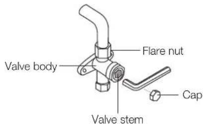
text_image
Valve body Flare nut Valve stem Cap- Watch the pressure gauge for one minute to make sure that there is no change in pressure. The pressure gauge should read slightly higher than atmospheric pressure.
- Remove the charge hose from the service port.
- Using hexagonal wrench, fully open both the high pressure and low pressure valves.
- Tighten valve caps on all three valves (service port, high pressure, low pressure) by hand. Tighten valves caps to ensure a leak tight connection using a torque wrench.
Note on adding refrigerant
Some systems require additional charging depending on pipe lengths. The additional refrigerant to be charged can be calculated using the below.

CAUTION
- Refrigerant charging must be performed after wiring, vacuuming, and the leak testing.
- Do not exceed the maximum allowable quantity of refrigerant or overcharge the system. Doing so can damage the unit or impact its functioning.
- Charging with unsuitable substances may cause explosions or accidents. Ensure that the appropriate refrigerant is used.
- Refrigerant containers must be opened slowly. Always use protective gear when charging the system.
- Do not mix refrigerant types.
Additional refrigerant per pipe length
| Connective pipe length (m) | Air purging method | Additional refrigerant | |
| More than (pre-charge pipe length x N) m | Vacuum pump | Liquid side:ø6.35mm (ø1/4")R410A(Total pipe length – pre-charge pipe length x N) x 12g/m | Liquid side:ø9.52mm (ø3/8")R32(Total pipe length – pre-charge pipe length x N) x 24g/m |
- Do not mix refrigerant types. Some systems require additional charging depending on pipe lengths.
Safety and leakage check
Electrical safety check
Perform the electrical safety check after completing installation. Cover the following areas:
- Insulated resistance. The insulated resistance must be more than 2MΩ.
- Grounding work. After finishing grounding work, measure the grounding resistance by visual detection and using the grounding resistance tester. Make sure the grounding resistance is less than 4 .
- Electrical leakage check (performing during test while unit is on). During a test operation after completed installation, use the electroprobe and multimeter to perform an electrical leakage check. Turn off the unit immediately if leakage happens. Try and evaluate different solutions until the unit operates properly.
Gas leak check
- Soap-water method. Apply a soap-water solution or a liquid neutral detergent on the indoor unit connection or outdoor unit connections with a soft brush to check for leakage of the connecting points of the piping. If bubbles emerge, the pipes are experiencing leakage.
- Leak detector. Use the leak detector to check for leakage.
NOTE: The illustration is for example purposes only. The actual order of A, B, C, D, and E on the machine may be slightly different from the unit you purchased but the general shape will remain the same.
A, B, C, D are points for one-four type. A, B, C, D, and E are points for the one-five type.

text_image
Indoor unit check point Outdoor unit check point E D C B A8. KM test run
Before test run
A test run must be performed after the entire system has been completely installed. Confirm the following points before performing the test:
- Indoor and outdoor units are properly installed.
- Piping and wiring are properly connected.
- No obstacles near the inlet and outlet of the unit that might cause poor performance or product malfunction.
- Refrigeration system does not leak.
- Drainage system is unimpeded and draining to a safe location.
- Heating insulation is properly installed.
- Grounding wires are properly connected.
- Length of the piping and additional refrigerant stow capacity have been recorded.
- Power voltage is the correct voltage for the air conditioner.

CAUTION
Failure to perform the test run may result in unit damage, property damage, or personal injury.
Test run instructions
- Open both the liquid and gas stop valves.
- Turn on the main power switch and allow the unit to warm up.
- Set the air conditioner to COOL mode.
- For the indoor unit:
a. Ensure the wired control and its buttons work properly.
b. Double check to see if the room temperature is registered correctly.
c. Ensure the indicators on the wired control and the display panel on the indoor unit work properly.
d. Ensure the manual buttons on the indoor unit work properly.
e. Check to see that the drainage system is unimpeded and draining smoothly.
f. Ensure there is no vibration or abnormal noise during operation.
5. For the outdoor unit
a. Check to see if the refrigeration system is leaking.
b. Make sure there is no vibration or abnormal noise during operation.
c. Ensure the fan, noise, and water generated by the unit do not disturb your neighbours or pose a safety hazard.
6. Drainage test
a. For installations in new buildings, you should perform this test before finishing the ceiling.
b. Remove the test cover. Add 2,000ml of water to the tank through the attached tube.
c. Turn on the main power switch and run the air conditioner in COOL mode.
d. Listen to the sound of the drain pump to see if it makes any unusual noises.
e. Check to see that the water is discharged. It may take up to one minute before the unit begins to drain, depending on the drainpipe.
f. Make sure that there are no leaks in any of the piping.
g. Stop the air conditioner. Turn off the main power switch and reinstall the test cover.
NOTE: If the unit malfunctions or does not operate according to your expectations, please refer to the Troubleshooting section of the Owner's Manual before calling customer service.
9. KM automatic wiring/piping connection
Automatic wiring/piping connection function
More recent models now feature automatic connection of wiring/piping errors. Press the 'check switch' on the outdoor unit PCB board for 5 seconds until the LED displays "CE", indicating that this function is working, Approximately 5 – 10 minutes after the switch is pressed, the 'CE' disappears, meaning that the wiring/piping error is corrected and all wiring/piping is properly connected.

Check switch
LED display
How to activate this function
- Check that outside temperature is above 5^ C. (This function does not work when outside temperature is not above 5^ C.)
- Check that the stop valves of the liquid pipe and gas pipe are open.
- Turn on the breaker and wait at least 2 minutes.
- Press the check switch on the outdoor PCB board unit LED display 'CE'.
kaden ^
your perfect climate