
KDI36 - Refrigerator Kaden - Free user manual and instructions
Find the device manual for free KDI36 Kaden in PDF.

| Product Type | Ducted Air Conditioner (Split System) |
| Model | KDI36 |
| Brand | Kaden |
| Indoor Unit Dimensions (W x D x H) | 625 mm x 1200 mm x 380 mm |
| Outdoor Unit Dimensions (W x H x D) | 946 mm x 810 mm x 410 mm |
| Power Supply | 220-240 V, 1 Phase, 50 Hz |
| Circuit Breaker / Fuse Rating | 32 A |
| Refrigerant Type | R32 (Difluoromethane) |
| Refrigerant Flammability Class | Class 2.2 (Flammable) |
| Maximum Pipe Length | 65 m |
| Maximum Drop Height | 30 m |
| Operation Modes | Cooling, Heating, Fan Only, Auto |
| Control Method | Wired Controller (included) |
| Manual Operation | Yes (on indoor unit panel) |
| Fan Speeds | Low, Medium, High (adjustable via static pressure settings) |
| External Static Pressure Range | 0-200 Pa (4 selectable settings) |
| Drain Pump | Yes (with water level sensor) |
| Refrigerant Connections | Gas: 15.9 mm (5/8"), Liquid: 9.5 mm (3/8") |
| Installation Requirements | Must be installed by licensed technician (ARC for Australia) |
| Compliance Standards | AS/NZS 3000, AS/NZS 5149, Local codes |
| Accessories Included | Soundproof insulation sheath, drain joint, seal ring, wired controller, magnetic rings, display panel |
| Error Code Display | Yes (LED flash patterns and codes) |
| Auto Airflow Adjustment | Yes (via wired controller) |
| Warranty | Refer to manufacturer's warranty card |
Frequently Asked Questions - KDI36 Kaden
User questions about KDI36 Kaden
0 question about this device. Answer the ones you know or ask your own.
Ask a new question about this device
Download the instructions for your Refrigerator in PDF format for free! Find your manual KDI36 - Kaden and take your electronic device back in hand. On this page are published all the documents necessary for the use of your device. KDI36 by Kaden.
USER MANUAL KDI36 Kaden
DUCTED AIR CONDITIONER
Installation Manual
KDI Series
KDI36 | KDI42 | KDI48 | KDI60

natural_image
Line drawing of a rectangular electronic device with two slots and a side panel, no text or symbols presentImportant note
This appliance must be installed in accordance with:
Manufacturer's Installation Instructions
Current AS/NZS 3000, AS/NZS 5149
Local Regulations and Municipal Building Codes including local OH&S requirements
This appliance must be installed, maintained, and removed only by an Authorised Person.
For continued safety of this appliance, it must be installed and maintained in accordance with the manufacturer's Instructions.


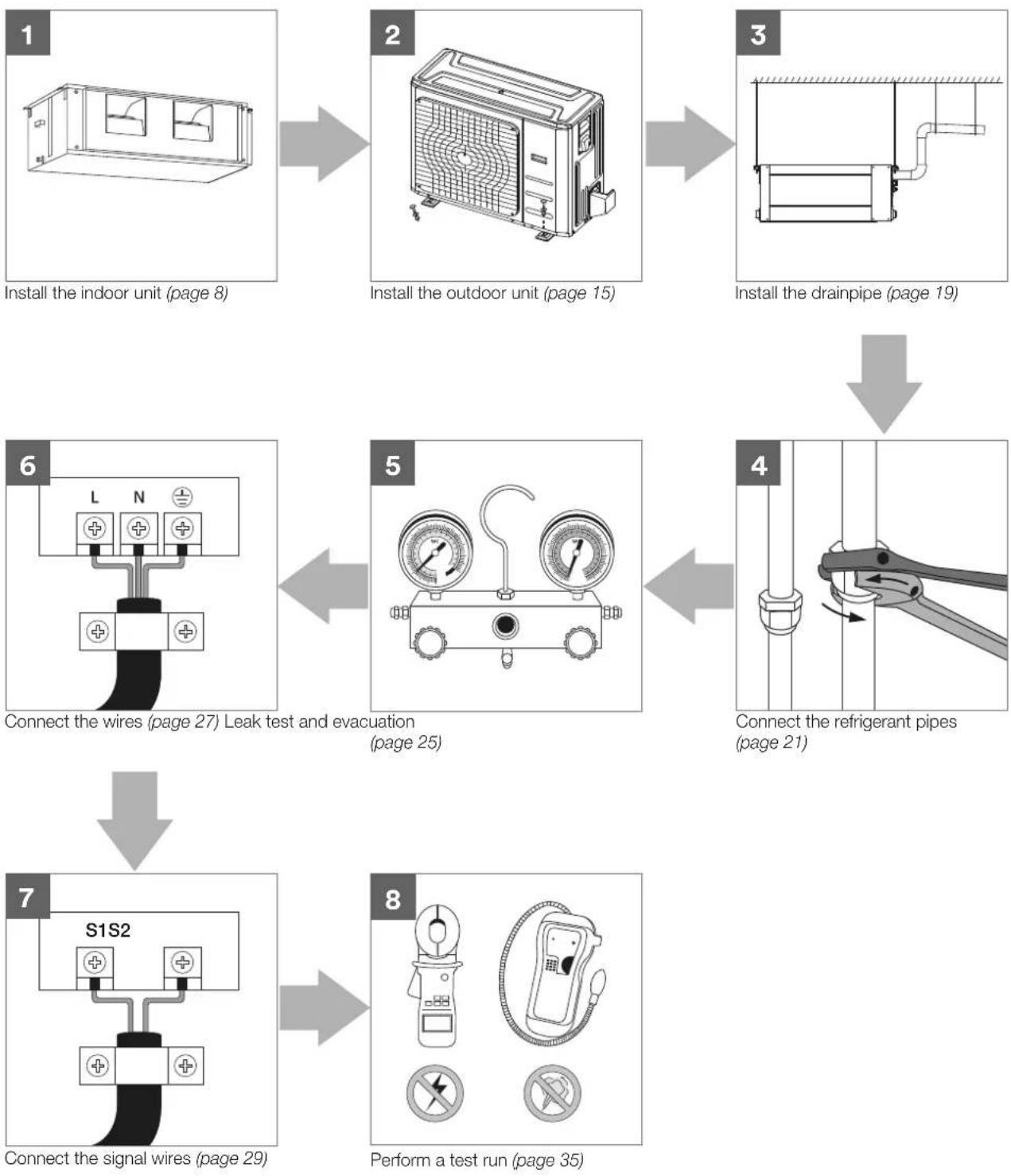
Table of contents
1. Safety precautions 4
Note about fluorinated gases 5
2. Accessories 6
3. Installation summary 7
4. Indoor unit installation 8
Indoor unit parts 8
Safety precautions 8
Indoor unit installation instructions 9
5. Outdoor unit installation 16
Outdoor unit installation instructions 16
Outdoor unit specifications 17
Drain joint installation 18
Notes on drilling hole in wall 18
6. Drainpipe installation 19
Note on drainpipe installation 19
7. Refrigerant piping connection 21
Safety precautions 21
Note on pipe length and elevation 21
Refrigerant piping connection instructions 22
Note on minimum bend radius 24
8. Leak testing and evacuation 25
Leak, pressure test and evacuation 25
Preparations and precautions 26
Before performing evacuation 26
Opening outdoor unit valves 26
Note on adding refrigerant 26
9. Wiring 27
Safety precautions 27
Power specifications 27
Signal wiring between outdoor and indoor units 29
Indoor unit wiring 29
10. Electrical checks 34
Electrical safety checks 34
Before test run 34
During test run 34
11. Test run 35
Before test run 35
Test run instructions 35
12. Manual operations 36
Manual operations 36
Error codes 37
Important note
Read this manual carefully before installing
or operating your new air conditioning unit.
Make sure to save this manual for future reference.
1. Safety precautions
Read safety precautions before operation and installation
Incorrect installation due to ignoring instructions can cause serious damage or injury.
The seriousness of potential damage or injuries is classified as either a WARNING or CAUTION.
This symbol is a WARNING, and indicates that ignoring instructions may cause death or serious injury.

This symbol is a CAUTION, and indicates that ignoring instructions may cause moderate injury to your person, or damage to your unit or other property.

This symbol indicates that you must never perform the action indicated.

WARNING
Do not share the electrical outlet with other appliances. Improper or insufficient power supply can cause fire or electrical shock.
When connecting refrigerant piping, do not let substances or gases other than the specified refrigerant enter the unit. The presence of other gases or substances will lower the unit's capacity, and can cause abnormally high pressure in the refrigeration cycle. This can cause explosion and injury.
Do not allow children to play with the air conditioner. Children must be supervised around the unit at all times.
- Installation must be performed by an authorised dealer or specialist. Defective installation can cause water leakage, electrical shock, or fire.
- Installation must be performed according to the installation instructions. Improper installation can cause water leakage, electrical shock, or fire.
- Contact an authorised service technician for repair or maintenance of this unit.
- Only use the included accessories, parts, and specified parts for installation. Using non-standard parts can cause water leakage, electrical shock, fire, and can cause the unit to fail.
-
Install the unit in a firm location that can support the unit's weight. If the chosen location cannot support the unit's weight, or the installation is not done properly, the unit may drop and cause serious injury and damage.
-
Only fully qualified licensed personnel should install, service or carry out maintenance to this air conditioning unit. All electrical work is to follow local and national wiring standards and the Installation Manual.
- You must use an independent circuit and single outlet to supply power. Do not connect other appliances to the same outlet. Insufficient electrical capacity or defects in electrical work can cause electrical shock or fire.
- For all electrical work, use the specified cables. Connect cables tightly, and clamp them securely to prevent external forces from damaging the terminal. Improper electrical connections can overheat and cause fire, and may also cause shock.
- All wiring must be properly arranged to ensure that the control board cover can close properly. If the control board cover is not closed properly, it can lead to corrosion and cause the connection points on the terminal to heat up, catch fire, or cause electrical shock.
- In certain functional environments, such as kitchens, server rooms, etc., the use of specially designed air-conditioning units is highly recommended.
- This appliance can be used by children aged from 8 years and above and persons with reduced physical, sensory or mental capabilities or lack of experience and knowledge if they have been given supervision or instruction concerning use of the appliance in a safe way and understand the hazards involved. Children must not play with the appliance. Cleaning and user maintenance must not be made by children without supervision.

AUTION
Do not install the unit in a location that may be exposed to combustible gas leaks. If combustible gas accumulates around the unit, it may cause fire.
Do not operate your air conditioner in a wet room such as a bathroom or laundry room. Too much exposure to water can cause electrical components to short circuit.
-
The product must be properly grounded at the time of installation, or electrical shock may occur.
-
Install drainage piping according to the instructions in this manual. Improper drainage may cause water damage to your home and property.
Note about fluorinated gases
- This air-conditioning unit contains fluorinated gases. For specific information on the type of gas and the amount, please refer to the relevant label on the unit itself.
- Installation, decommissioning, service, maintenance and repair of this unit must be performed by a licensed technician.
- Product decommissioning and recycling must be performed by a licensed technician.
- If the system has a leak-detection system installed, it must be checked for leaks at least every 12 months.
- When the unit is checked for leaks, proper record-keeping of all checks is strongly recommended.
- Only ARC (Australian Refrigeration Council) licence holders can install and commission this air conditioner. This air conditioner must be installed to meet the requirements of the current version of AS/NZS 5149.
- It is illegal to vent some types of refrigerant to the atmosphere.

REFRIGERANT
This appliance uses R32 (difluoromethane) refrigerant, which is a flammable gas class 2.2 according to AS/NZS 5149 and must be handled by a refrigeration mechanic with appropriate Australian refrigerant handling licence.
- WARNING risk of fire/flammable material. If the refrigerant is leaked, together with an external ignition source, there is possibility of ignition.
- Read all the OPERATING INSTRUCTIONS carefully before operation.
- Service personnel are required to carefully read the OPERATING INSTRUCTIONS and INSTALLATION MANUAL before operation.
• Further information is available in the OPERATING INSTRUCTIONS, INSTALLATION MANUAL and the like.
Certain levels of refrigerant require minimum room sizes. Please ensure that these minimum room sizes are adhered to for standard installations (up to 10m pipe length). If larger refrigerant charges than standard are used then please consult AS/NZS 60335.2.40 to determine the safe minimum floor area for the installation.
Make sure that the area has been made safe by having suitable ventilation and is free from ignition sources before charging or recovering the charge of R32.
2. Accessories
The air conditioning system comes with the following accessories. Use all of the installation parts and accessories to install the air conditioner. Improper installation may result in water leakage, electrical shock and fire, or cause the equipment to fail.
| Name Shape Quantity | |||
| Tubing and fittings Soundproof/insulation sheath |  | 2 | |
| Cooling and heating | Drain joint |  | 1 |
| Seal ring | 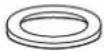 | 1 | |
| Others | Owner's manual |  | 1 |
| Installation manual |  | 1 | |
| Display panel (for testing purposes only) | 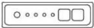 | 1 | |
| EMC magnetic ring | Magnetic ring - wrap the electric wires S1 & S2 around the magnetic ring twice |  | 1 |
| Magnetic ring - hitch on the connective cable between the indoor unit and outdoor unit after installation |  | KDI36 = 2KDI42 = 1KDI48 = 1KDI60 = 0 | |
| Wired controller | Wired controller 1 |  | |
| Wired controller manual |  | 1 | |
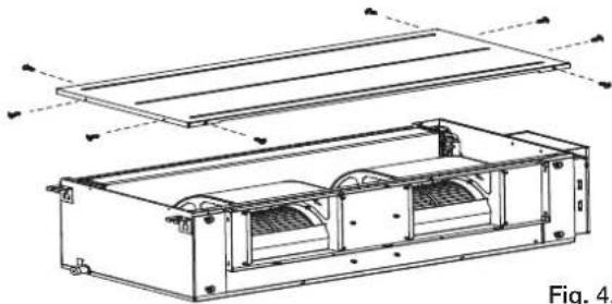
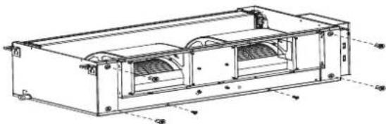
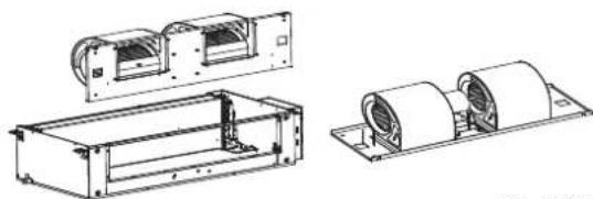
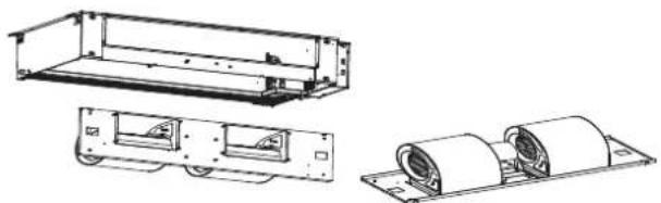
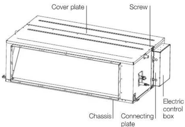
4. Indoor unit installation
Indoor unit parts
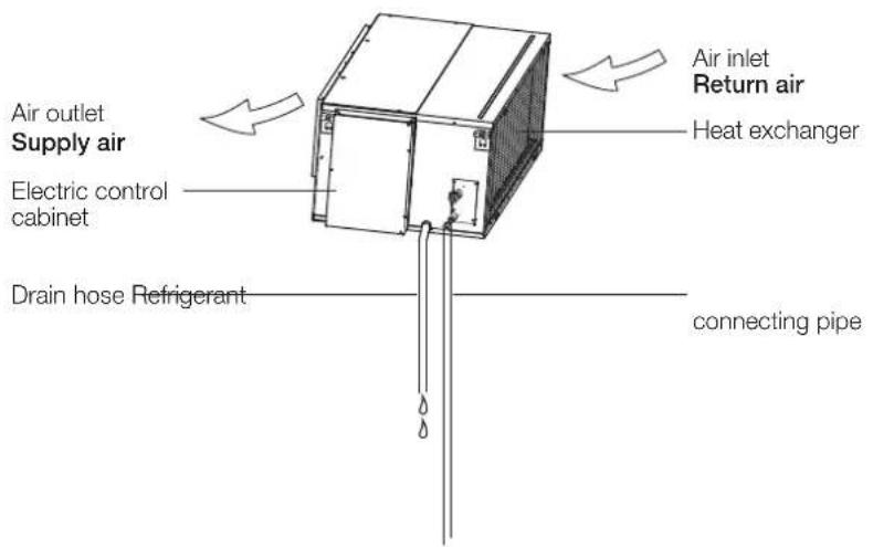
Fig. 4.1 (applicable to KDI36, KDI42, KDI48 and KDI60)
- Upon delivery, the package should be checked and any damage should be reported immediately.
-
When handling the unit, take into account the following: The unit is fragile, handle the unit with care.
-
Keep the unit upright in order to avoid compressor damage.
- When lifting the unit, always use protectors to prevent belt damage and pay attention to the position of the unit's centre of gravity.
Safety precautions

WARNING
Securely install the indoor unit on a structure that can sustain its weight. If the structure is too weak, the unit may fall, causing personal injury, unit and property damage, or even death.

AUTION
Install the indoor and outdoor units, cables and wires at least 1m from televisions or radios to prevent static or image distortion. Depending on the appliances, a 1m distance may not be sufficient.
DO NOT install unit in the following locations:
✗ Where oil drilling or fracking is taking place.
× Coastal areas with high salt content in the air.
× Areas with caustic gases in the air, such as near hot springs.
× Areas with power fluctuations, such as factories.
✗ Enclosed spaces, such as cabinets.
✗ Areas with strong electromagnetic waves.
× Areas that store flammable materials or gas.
× Rooms with high humidity, such as bathrooms or laundry rooms.
Indoor unit installation instructions
Step 1: Select installation location
The indoor unit should be installed in a location that meets the following requirements:
√ Enough room for installation and maintenance.
√ Enough room for the connecting pipe and drainpipe.
√ The ceiling is horizontal and its structure can sustain the weight of the indoor unit.
√ The air inlet and outlet are not impeded.
√ The airflow can fill the entire room.
√ There is no direct radiation from heaters.
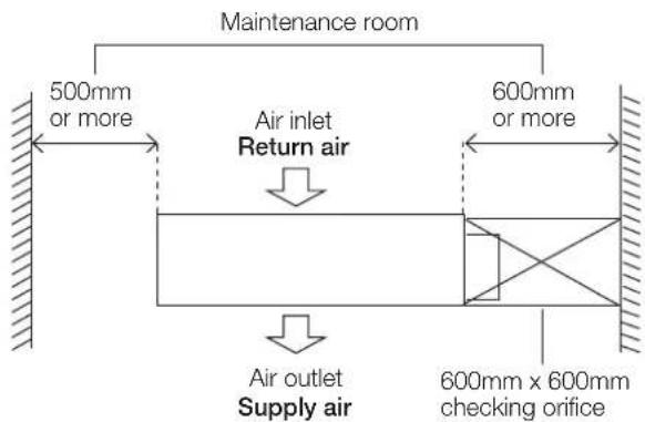
Fig. 4.2
Step 2: Hang indoor unit
- Please refer to the following diagrams to locate the four positioning screw bolt holes on the ceiling. Be sure to mark the places where you will drill ceiling hook holes.
This unit has been installed with an air intake pipe flange, but there is no air filter. (See Fig. 4.3 and Fig. 4.4)
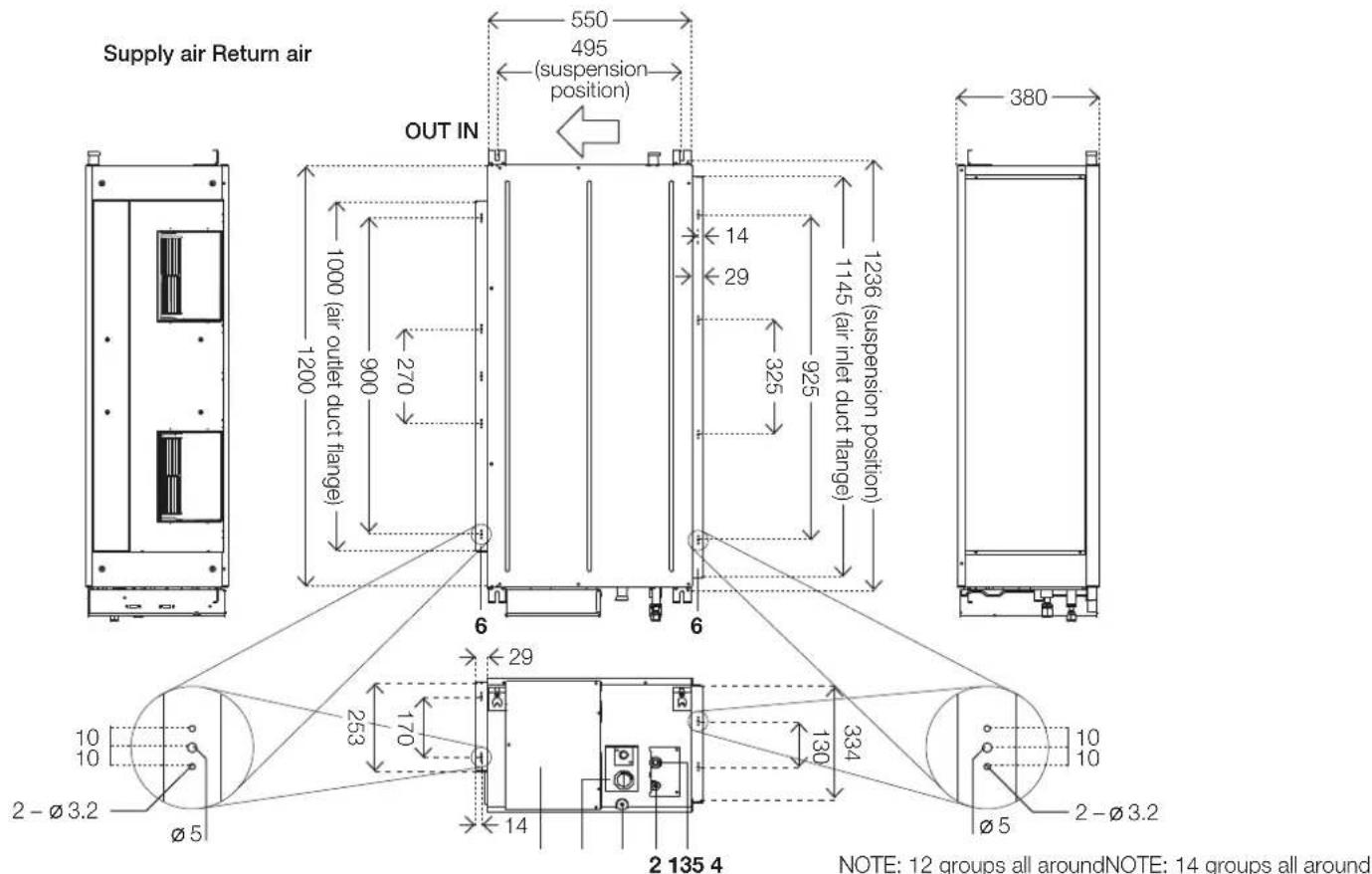
Fig. 4.3 (applicable to KDI36, KDI42 and KDI48)

Fig. 4.4 (applicable to KDI60 only)
Table 4.1
| Number Name Description | |
| 1 Gas pipe connection | 15.9 (KDI36, KDI42 and KDI48) 19 (KDI60) |
| 2 Liquid pipe connection | 9.5 |
| 3 Drain pipe connection OD | 25 ID 20 |
| 4 Drain pipe connection Using drain pump | |
| 5 Power supply connection – | |
| 6 Air discharge flange – |

Fig. 4.5 (applicable to KDI36, KDI42, KDI48 and KDI60)
Table 4.2
| Model | Outline dimension | Size of mounted lug | Air outlet opening size (symmetry of air outlet opening) | Air inlet opening size (symmetry of air inlet opening) | |||||||||||
| A | B | C | D | E | F | G | H | I | J | K | L | M | N | O | |
| KDI36, KDI42 & KDI48 | 625mm | 1200mm | 380mm | 495mm | 1236mm | 1000mm | 253mm | 270mm | 900mm | 170mm | 1145mm | 334mm | 325mm | 925mm | 130mm |
| KDI60 | 858mm | 1400mm | 440mm | 700mm | 1436mm | 1188mm | 385mm | 500mm | 1000mm | 280mm | 1188mm | 385mm | 500mm | 1000mm | 290mm |
Table 4.3
| Number Name Description | ||
| 1 Gas pipe connection | 15.9 (KDI36, KDI42 and KDI48) | |
| 2 Liquid pipe connection | 9.5 | |
| 3 | Drain pipe connection | OD 25 ID 20 |
| 4 | Drain pipe connection | Using drain pump |
| 5 | Power supply connection | - |
| 6 | Air inlet duct flange | Some models |
| 7 Air outlet duct flange | - | |
Wood
Place the wood mounting across the roof beams, then install the hanging screw bolts. (See Fig. 4.6)

Fig. 4.6
New concrete bricks
Inlay or embed the screw bolts. (See Fig. 4.7)

Blade shape insertion

Slide insertion
Fig. 4.7
Original concrete bricks
Use an embedding screw bolt, crock and stick harness. (See Fig. 4.8)

Fig. 4.8
Steel roof beam structure
Install and use the supporting steel angle. (See Fig. 4.9)
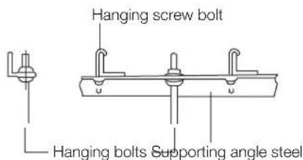
Fig. 4.9

AUTION
The unit body must be completely aligned with the hole. Ensure that the unit and the hole are the same size before moving on.
-
Install and fit pipes and wires after you have finished installing the main body. When choosing where to start, determine the direction of the pipes to be drawn out. Especially in cases where there is a ceiling involved, align the refrigerant pipes, drain pipes, and indoor and outdoor lines with their connection points before mounting the unit.
-
Install hanging screw bolts.
-
Cut off the roof beam.
-
Strengthen the point at which the cut was made. Consolidate the roof beam.
-
Drill 4 holes 10cm deep at the ceiling hook positions in the internal ceiling. Be sure to hold the drill at a 90° angle to the ceiling.
- Secure the bolt using the washers and nuts provided.
- Install the four suspension bolts.
- Mount the indoor unit with at least two people to lift and secure it. Insert suspension bolts into the unit's hanging holes. Fasten them using the washers and nuts provided. (See Fig. 4.10)
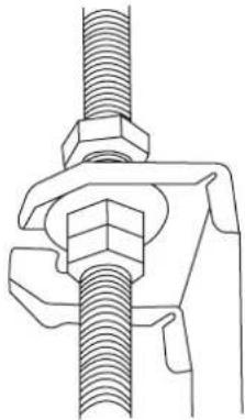
natural_image
Technical line drawing of a mechanical clamp or fastener assembly (no text or symbols)Fig. 4.10
- Mount the indoor unit onto the hanging screw bolts with a block. Position the indoor unit flat using a level indicator to prevent leaks. (See Fig. 4.9)
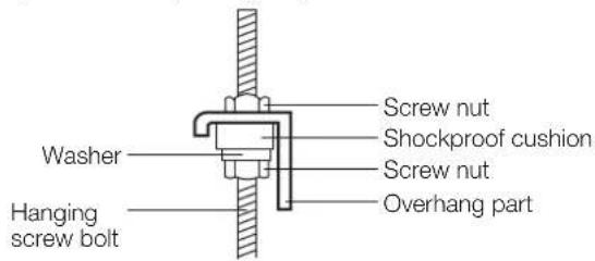
Fig. 4.11
NOTE: Confirm the minimum drain tilt is 1/100 or more.
Step 3: Diagrammatic sketch for installing the main body
Installing the dust-proof net and canvas air passage
- Install the dust proof net according to the installation manual.
- Install the canvas air passage underneath the dust-proof net.
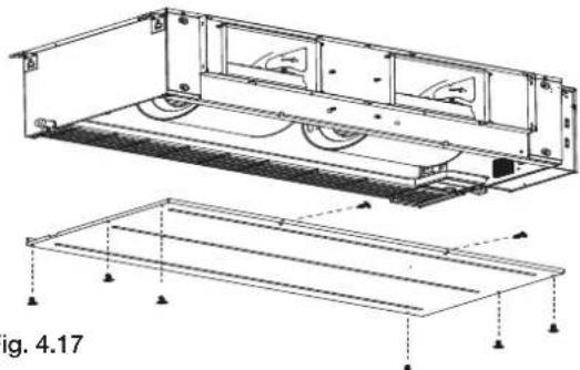
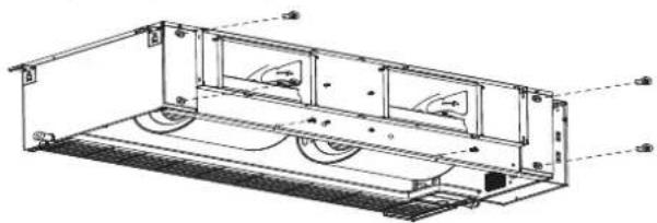
Step 4: Duct and accessories installation
- The air inlet and air outlet duct should be far enough apart to prevent air from the outlet entering the air inlet. Please attach the outside air duct to the indoor air outlet/inlet flange by using the type ST3.9 x 10 screw.
- Connect the duct according to the following diagram:

Fig. 4.12
Note
- Do not place the connecting duct weight on the indoor unit.
- When connecting the duct, use a non-flammable flexible tie-in to prevent vibrating.
- When connecting the duct, install in place prone to takedown for maintenance.
- Change the fan motor static pressure corresponding to external duct static pressure.
- If installed in a place like a meeting room where noise is easy to be perceived, design isolation booth and internal duct underlayer to muffle the duct system and weaken the air encounter noise in the duct.
Step 5: Motor and drain pump maintenance
Pump maintenance
- Remove four screws from the drain pump.
- Unplug the pump power supply and water level switch cable.
- Detach the pump.

Fig. 4.13
Motor maintenance
There are three methods:
- Remove the top plate from the top.
- Remove the top cover as shown.
natural_image
Technical line drawing of an electronic device with internal components and mounting brackets (no text or symbols)Fig. 4.14
- Loosen the four bolts and two screws which are used to fasten the front side plate.
natural_image
Technical line drawing of a mechanical device with internal components and mounting holes (no text or symbols)Fig. 4.15
- Remove the cord of the motor, take off the front side plate and repair the motor.
natural_image
Technical line drawings of mechanical components, including a housing, rollers, and a base plate (no text or symbols)Fig. 4.16
- Remove the bottom plate from the bottom.
- Remove the bottom base as shown.
natural_image
Technical line drawing of a mechanical assembly with mounting brackets and structural supports (no text or symbols)- Loosen the four bolts and two screws which are used to fasten the front side plate (be careful, the front side plate may fall down).
natural_image
Technical line drawing of a mechanical assembly with wheels and mounting brackets (no text or symbols)Fig. 4.18
- Remove the cord of the motor, take off the front side plate and repair the motor.
natural_image
Technical line drawings of mechanical components including a frame, housing, and cylindrical rollers (no text or symbols)Fig. 4.19
- Repair it directly (only applicable to plastic scroll and fan wheel).
• Take off the chassis assembly.
• Take off the volute.
• Take off the motor.

Fig. 4.20
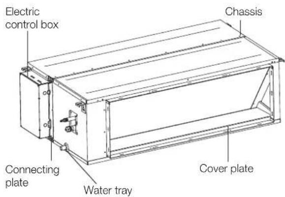
Disconnect-type installation
- Remove the cover of the electric control box and pull out the temperature sensor line and water pump line (water distribution pump model) from the main control board.
- Remove 6 screws on the top cover and 3 screws on the connecting plate of the left side plate.
- Remove the connecting plate on the left side panel.
- Separate the box and pull out the temperature sensing envelope/water pump line from the wire through hole in the electric control box.

- Move the two boxes to the installation position (the chassis faces up and the water tray faces down).
- Connect the temperature sensing cable/water pump cable to the main board in the electric control box.
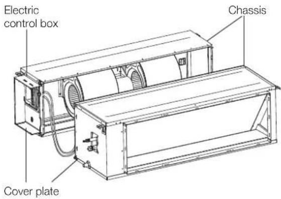
- Combine the two boxes and fix the chassis a connecting plates on both sides with screws.
NOTE: When merging, the sensor line or water pump line cannot be clamped by the box.
5. Outdoor unit installation
Outdoor unit installation instructions
Step 1: Select installation location
The outdoor unit should be installed in the location that meets the following requirements:
√ Place the outdoor unit as close to the indoor unit as possible.
√ Ensure that there is enough room for installation and maintenance.
√ The air inlet and outlet must not be obstructed or exposed to strong wind.
√ Ensure the location of the unit will not be subject to snowdrifts, accumulation of leaves or other seasonal debris. If possible, provide an awning for the unit.
√ Ensure the awning does not obstruct airflow.
√ The installation area must be dry and well ventilated.
√ There must be enough room to install the connecting pipes and cables and to access them for maintenance.
√ The support is flat and horizontal and can stand the weight of the outdoor unit, and will not add additional noise or vibration.
√ It is easy to install the connecting pipes or cables.
√ Determine the air outlet direction where the discharged air is not blocked. If necessary, install a blind that does not interfere with the air flow.
√ The area must be free of combustible gases and chemicals.
√ The pipe length between the outdoor and indoor unit may not exceed the maximum allowable pipe length.
√ If possible, do not install the unit where it is exposed to direct sunlight.
NOTE: All the pictures in this manual are for explanation purpose only. They may be slightly different from the air conditioner you purchased. The actual shape shall prevail.

Fig. 5.1
√ If possible, make sure the unit is located far away from your neighbours' property so that the noise from the unit will not disturb them.
√ If the location is exposed to strong winds (for example: near a seaside), the unit must be placed against the wall to shelter it from the wind. If necessary, use an awning. (See Fig. 5.1 and Fig. 5.2)
√ Install the indoor and outdoor units, cables and wires at least 1 metre from televisions or radios to prevent static or image distortion. Depending on the radio waves, a 1 metre distance may not be enough to eliminate all interference.
√ During heating mode, condensate should be well drained away by the drain hole to an appropriate place, so as not to interfere with other people.
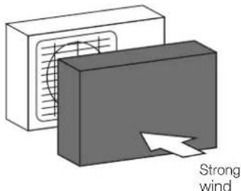
Fig. 5.2
Step 2: Install outdoor unit
Fix the outdoor unit with anchor bolts (M10).
CAUTION
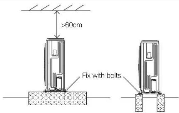
Fig. 5.3
- Be sure to remove any obstacles that may block air circulation.
- Make sure you refer to length specifications to ensure there is enough room for installation and maintenance.
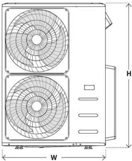
Outdoor unit specifications
Split type outdoor unit
(Refer to Fig. 5.4, Fig. 5.5, Fig. 5.6, Fig. 5.7 and Table 5.1)
Fig. 5.4

natural_image
Technical line drawing of a dual-panel air conditioner unit with labeled dimensions (W and H), no text or symbols present.Fig. 5.5
natural_image
Technical line drawing of a dual-panel air conditioning unit with labeled dimensions (W and H), no text or symbols present.Fig. 5.6
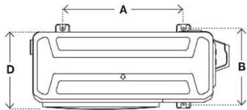
Table 5.1 Length specifications of split type outdoor unit
| Model | Outdoor unit dimensions W x H x D | Mounting dimensions | |
| Distance A | Distance B | ||
| KDI36 | 946mm x 810mm x 410mm | 673mm | 403mm |
| KDI42, KDI48 & KDI60 | 952mm x 1333mm x 415mm | 634mm | 404mm |
NOTE: The minimum distance between the outdoor unit and walls described in the installation guide does not apply to airtight rooms. Be sure to keep the unit unobstructed in at least two of the three directions (M, N, P). (See Fig. 5.7)
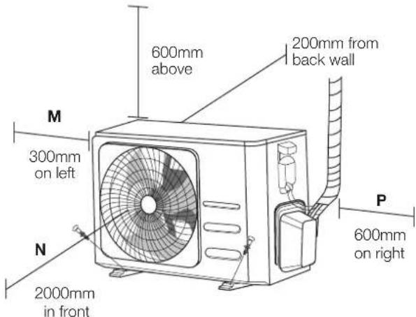
Fig. 5.7
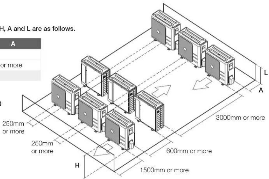
Rows of series installation
Table 5.2 The relations between H, A and L are as follows.
| L | A | |
| L ≤ HL ≤ 1/2H 250mm or more | ||
| 1/2H < L ≤ H 300mm or more | ||
| L > H Can not be installed | ||
Fig. 5.8
Drain joint installation
If the drain joint comes with a rubber seal (See Fig. 5.9 A), do the following:
- Fit the rubber seal on the end of the drain joint that will connect to the outdoor unit.
- Insert the drain joint into the hole in the base pan of the unit.
- Rotate the drain joint 90irc until it clicks in place facing the front of the unit.
- Connect a drain hose extension (not included) to the drain joint to redirect water from the unit during heating mode.
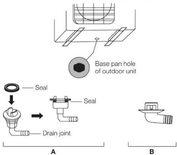
Fig. 5.9
If the drain joint doesn't come with a rubber seal (See Fig. 5.9 B), do the following:
- Insert the drain joint into the hole in the base pan of the unit. The drain joint will click in place.
- Connect a drain hose extension (not included) to the drain joint to redirect water from the unit during heating mode.
NOTE: Make sure the water drains to a safe location where it will not cause water damage or a slipping hazard.
Notes on drilling hole in wall
You must drill a hole in the wall for the refrigerant piping, and the signal cable that will connect the indoor and outdoor units.
- Determine the location of the wall hole based on the location of the outdoor unit.
- Using a 65mm core drill, drill a hole in the wall. NOTE: When drilling the wall hole, make sure to avoid wires, plumbing, and other sensitive components.
- Place the protective wall cuff in the hole. This protects the edges of the hole and will help seal it when you finish the installation process.
6. Drainpipe installation
The drainpipe is used to drain water away from the unit. Improper installation may cause unit and property damage.

AUTION
• Insulate all piping to prevent condensation, which could lead to water damage.
- If the drainpipe is bent or installed incorrectly, water may leak and cause a water-level switch malfunction.
- In HEAT mode, the outdoor unit will discharge water. Ensure that the drain hose is placed in an appropriate area to avoid water damage and slippage.
- Do not pull the drainpipe forcefully. This could disconnect it.
Indoor drainpipe installation
Install the drainpipe as illustrated in Fig. 6.1.

Fig. 6.1
- Cover the drainpipe with heat insulation to prevent condensation and leakage.
- Attach the mouth of the drain hose to the unit's outlet pipe. Sheath the mouth of the hose and clip it firmly with a pipe clasp. (See Fig. 6.2)

Fig. 6.2
Note on drainpipe installation
- When using an extended drainpipe, tighten the indoor connection with an additional protection tube. This prevents it from pulling loose.
- The drainpipe should slope downward at a gradient of at least 1/100 to prevent water from flowing back into the air conditioner.
- To prevent the pipe from sagging, space hanging wires every 1 – 1.5m.
- If the outlet of the drainpipe is higher than the body's pump joint, use a lift pipe for the indoor unit's exhaust outlet. The lift pipe must be installed no higher than 55cm from the ceiling board. The distance between the unit and the lift pipe must be less than 20cm. Incorrect installation could cause water to flow back into the unit and flood.
- To prevent air bubbles, keep the drain before the riser level or sloping slightly up.
Drainpipe installation for units with a pump
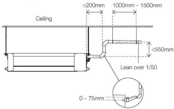
Fig. 6.3
NOTE: If the drain pump spigot is not used, the drain pump will still engage if the drain tray fills and activates the water level sensor. This can lead to water leakage. Possible actions to avoid water leakage:
- Disconnect power to drain pump.
-
Plumb drain pump spigot into gravity fed drain
-
Using a 65mm core drill, drill a hole in the wall. Make sure that the hole is drilled at a slight downward angle, so that the outdoor end of the hole is lower than the indoor end by about 12mm. This will ensure proper water drainage (See Fig. 6.4). Place the protective wall cuff in the hole. This protects the edges of the hole and will help seal it when you finish the installation process.
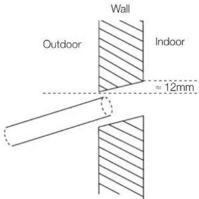
Fig. 6.4
NOTE: When drilling the hole, make sure to avoid wires, plumbing, and other sensitive components.
- Pass the drain hose through the wall hole. Make sure the water drains to a safe location where it will not cause water damage or a slipping hazard.
NOTE: The drainpipe outlet should be at least 5cm above the ground. If it touches the ground, the unit may become blocked and malfunction. Make sure that the drain has a U or S pipe to catch odours that might otherwise come back into the house.
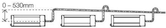
NOTE: When connecting multiple drainpipes, install the pipes as shown in Fig. 6.5.
With drain pump
Without drain pump
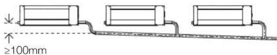
Fig. 6.5
Drainage pump test procedure
Check that the drainpipe is unhindered. This test should be performed on newly built houses before the ceiling is surfaced.
- Remove the test cover. Fill the water pan with 2 litres of water.
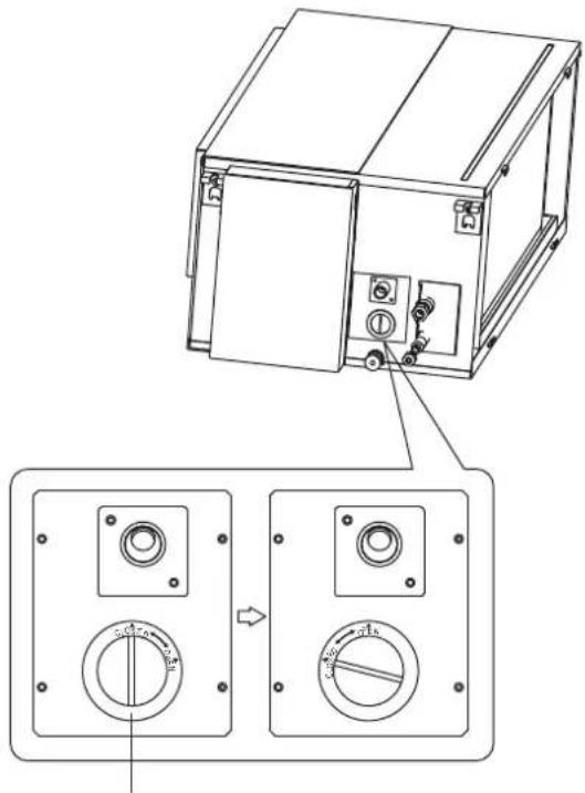
Fig. 6.6

Fig. 6.7
-
Turn on the unit in COOLING mode. You will hear the drain pump. Check whether the water is discharged properly (a 1 minute lag is possible, depending on the length of the drain pipe). Check whether water leaks from the joints.
-
Turn off the air conditioner and put the cap back on.
7. Refrigerant piping connection
Safety precautions

WARNING
- All filed piping must be completed by an ARC licensed technician and must comply with all local and national regulations including AS/NZS 5149 and Australian wiring regulations.
- When the air conditioner is installed in a small room, measures must be taken to prevent the refrigerant concentration in the room from exceeding the safety limit in the event of refrigerant leakage. If the refrigerant leaks and its concentration exceeds its proper limit, hazards due to lack of oxygen may result.
- When installing the refrigeration system, ensure that air, dust, moisture or foreign substances do not enter the refrigerant circuit. Contamination in the system may cause poor operating capacity, high pressure in the refrigeration cycle, explosion or injury.
- Ventilate the area immediately if there is refrigerant leakage during the installation. Leaked refrigerant gas is both toxic and flammable. Ensure there is no refrigerant leakage after completing the installation work.
Note on pipe length and elevation
Ensure that the length of the refrigerant pipe, the number of bends, and the drop height between the indoor and outdoor units meets the requirements shown in the following table:
Table 7.1 The maximum length and drop height based on models. (Unit: metres)
| Type of model Length of piping Maximum drop height | |
| KDI36, KDI42, KDI48 and KDI60 | 65 30 |

AUTION
Oil traps
If oil flows back into the outdoor unit's compressor when the indoor unit is installed higher than the outdoor unit, this might cause liquid compression or deterioration of oil return.
Oil traps in the rising gas piping can prevent this. An oil trap should be installed every 10m of vertical gas piping. (See Fig. 7.1)

The indoor unit is installed higher than the outdoor unit
Fig. 7.1

AUTION
If the outdoor unit is installed higher than the indoor unit:
It is recommended that vertical suction risers not be up-sized. Proper oil return to the compressor should be maintained with suction gas velocity. If velocities drop below 7.62m/s, oil return will be decreased. An oil trap should be installed every 6m of vertical gas piping. (See Fig. 7.2)

The outdoor unit is installed higher than the indoor unit
Fig. 7.2
Refrigerant piping connection instructions

CAUTION
- The branching pipe must be installed horizontally. An angle of more than 10irc may cause malfunction.
- Do not install the connecting pipe until both indoor and outdoor units have been installed.
• Insulate both the gas and liquid piping to prevent water leakage.
Step 1: Cut pipes
When preparing refrigerant pipes, take extra care to cut and flare them properly. This will ensure efficient operation and minimise the need for future maintenance.
- Measure the distance between the indoor and outdoor units.
- Using a pipe cutter, cut the pipe a little longer than the measured distance.

AUTION
Do not deform pipe while cutting. Be extra careful not to damage, dent, or deform the pipe while cutting. This will drastically reduce the heating efficiency of the unit.
- Make sure that the pipe is cut at a perfect 90irc angle. Refer to Fig. 7.3 for examples of good and bad cuts.

natural_image
Four identical 3D-rendered cylindrical objects with wavy surfaces, no text or symbols present90° Oblique Rough Warped
Fig. 7.3
Step 2: Remove burrs
Burrs can affect the airtight seal of the refrigerant piping connection. They must be completely removed.
-
Hold the pipe at a downward angle to prevent burrs from falling into the pipe.
-
Using a reamer or deburring tool, remove all burrs from the cut section of the pipe.
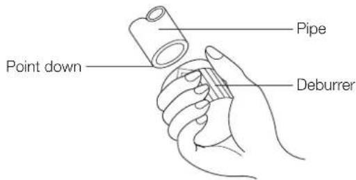
Fig. 7.4
Step 3: Flare pipe ends
Proper flaring is essential to achieve an airtight seal.
-
After removing burrs from cut pipe, seal the ends with PVC tape to prevent foreign materials from entering the pipe.
-
Sheath the pipe with insulating material.
-
Place flare nuts on both ends of pipe. Make sure they are facing in the right direction, because you can't put them on or change their direction after flaring. (See Fig. 7.5)

Fig. 7.5
-
Remove PVC tape from ends of pipe when ready to perform flaring work.
-
Clamp flare form on the end of the pipe. The end of the pipe must extend beyond the flare form.
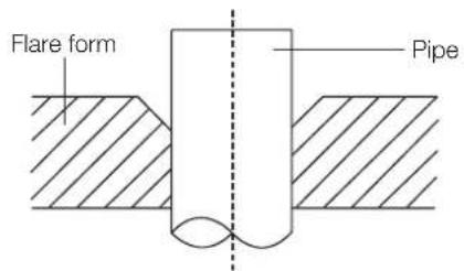
Fig. 7.6
-
Place flaring tool onto the form.
-
Turn the handle of the flaring tool clockwise until the pipe is fully flared. Flare the pipe in accordance with the dimensions shown in Table 7.2.
Table 7.2 Piping extension beyond flare form
| Pipe gauge | Tightening torque | Flare dimension (A) (Unit: mm) |
| Min. Max. | ||
| ∅ 9.5 25 - 26 N.m(255 - 265 kgf.cm) | 13.2 13.5 | |
| ∅ 15.9 45 - 47 N.m(459 - 480 kgf.cm) | 19.2 19.7 | |
| ∅ 19.1 65 - 67 N.m(663 - 683 kgf.cm) | 23.2 23.7 | |
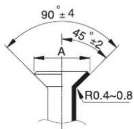
Fig. 7.7
- Remove the flaring tool and flare form, then inspect the end of the pipe for cracks and even flaring.
Step 4: Connect pipes
Connect the copper pipes to the indoor unit first, then connect it to the outdoor unit. You should first connect the low pressure pipe, then the high pressure pipe.
- When connecting the flare nuts, apply a thin coat of refrigeration oil to the flared ends of the pipes.
- Align the centre of the two pipes that you will connect.
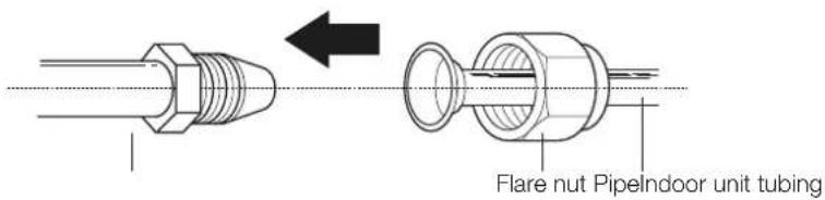
Fig. 7.8
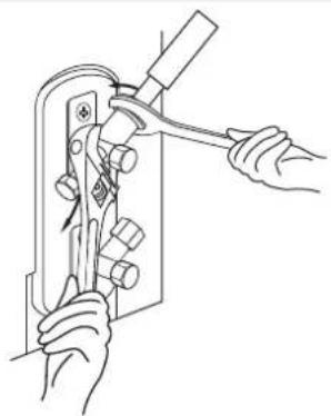
- Tighten the flare nut as tightly as possible by hand.
- Using a spanner, grip the nut on the unit tubing.
- While firmly gripping the nut, use a torque wrench to tighten the flare nut according to the torque values in Table 7.2.
NOTE: Use both a spanner and a torque wrench when connecting or disconnecting pipes to/from the unit.
natural_image
Line drawing of hands using a tool to adjust or install a mechanical component (no text or symbols present)Fig. 7.9

CAUTION
- Ensure that you wrap insulation around the piping. Direct contact with the bare piping may result in burns or frostbite.
- Make sure the pipe is properly connected. Over-tightening may damage the bell mouth and under-tightening may lead to leakage.
Note on minimum bend radius
Carefully bend the tubing in the middle according to the diagram below. Do not bend the tubing more than 90irc or more than 3 times.
Bend the pipe with thumb
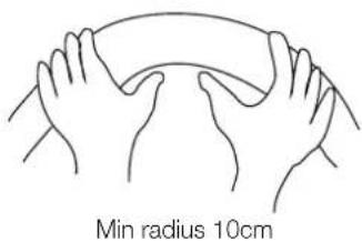
Fig. 7.10
- After connecting the copper pipes to the indoor unit, wrap the power cable, signal cable and the piping together with binding tape.
NOTE: Do not intertwine signal cable with other wires. While bundling these items together, do not intertwine or cross the signal cable with any other wiring.
- Thread this pipeline through the wall and connect it to the outdoor unit.
- Insulate all the piping, including the valves of the outdoor unit.
- Open the stop valves of the outdoor unit to start the flow of the refrigerant between the indoor and the outdoor unit.

CAUTION
Check to make sure there is no refrigerant leak after completing the installation work. If there is a refrigerant leak, located and repair the leak before evacuating the system (refer to the Leak testing and evacuation section of this manual).
8. Leak testing and evacuation
natural_image
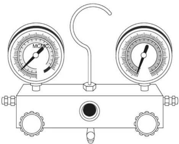
Line drawing of a pressure gauge with two gauges and a central hub, no text or symbols present.Leak, pressure test and evacuation
The interconnecting pipe work and indoor unit must be pressure tested at 1000kpa and leak tested before being evacuated. Before using the manifold gauge and vacuum pump, read their operation manuals to familiarise yourself with how to use them properly.
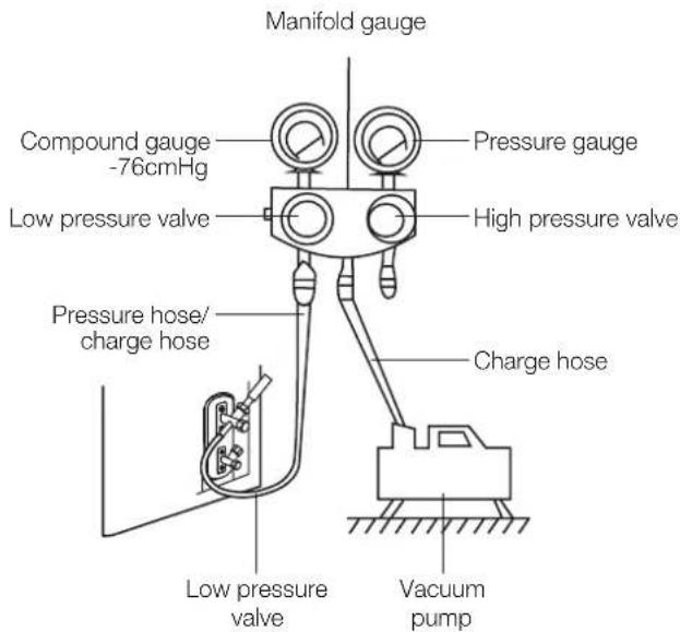
Fig. 8.1
- Connect the charge hose of the manifold gauge to the outdoor unit's low pressure valve.
- Connect another charge hose from the manifold gauge to the vacuum pump.
- Monitor test pressure and check with a leak detector and bubble solution. Safely release the test pressure.
- Open the Low pressure side of the manifold gauge. Keep the High pressure side closed.
- Turn on the vacuum pump to evacuate the system.
- Evacuate the interconnecting pipes to <=500 microns.
- Close the low pressure side of the manifold gauge, and turn off the vacuum pump.
- Wait for 5 minutes, then check that there has been no change in system vacuum.
- If the vacuum does not settle, repeat from Step 1 of Leak, pressure test and evacuations. If there is no change in system vacuum, unscrew the cap from the packed valve (high pressure valve).
Preparations and precautions
Air and foreign matter in the refrigerant circuit can cause abnormal rises in pressure, which can damage the air conditioner, reduce its efficiency, and cause injury. Use a vacuum pump and manifold gauge to evacuate the refrigerant circuit, removing any non-condensible gas and moisture from the system.
Evacuation should be performed upon initial installation and when unit is relocated.
Before performing evacuation
√ Check to make sure that both high pressure and low pressure pipes between the indoor and outdoor units are connected properly in accordance with the Refrigerant piping connection section of this manual.
√ Pressure test the interconnecting pipes.
√ Check to make sure all wiring is connected properly.
Opening outdoor unit valves
- Insert hexagonal wrench into the packed valve (high-pressure valve) and open the valve by turning the wrench in a 1/4 counterclockwise turn. Listen for gas to exit the system, then close the valve after 5 seconds.
Fig. 8.2
- Watch the pressure gauge for one minute to make sure that there is no change in pressure. The pressure gauge should read slightly higher than atmospheric pressure.
- Remove the charge hose from the service port.
- Using hexagonal wrench, fully open both the high pressure and low pressure valves.
- Tighten valve caps on all three valves (service port, high pressure, low pressure) by hand. You may tighten it further using a torque wrench if needed.
Note on adding refrigerant
Some systems require additional charging depending on pipe lengths. The additional refrigerant to be charged can be calculated using the below.
Liquid side diameter
∅ 9.52mm/3/8"
| Total pipe length - Standard pipe length x 24g/m |
| Refrigerant type |
| R32 |
CAUTION
- Refrigerant charging must be performed after wiring, vacuuming, and the leak testing.
- Do not exceed the maximum allowable quantity of refrigerant or overcharge the system. Doing so can damage the unit or impact its functioning.
- Charging with unsuitable substances may cause explosions or accidents. Ensure that the appropriate refrigerant is used.
- Refrigerant containers must be opened slowly. Always use protective gear when charging the system.
- Do not mix refrigerant types.
9. Wiring
Safety precautions

WARNING
- Disconnect the power supply before working on the unit.
- All wiring must be performed according to local and national regulations, and must be installed by a licensed electrician.
- Wiring must be done by a qualified technician. Improper connections may cause electrical malfunction, injury, or fire.
- All electrical connections must be made according to the electrical connection diagram located on the panels of the indoor and outdoor units.
- If there is a serious safety issue with the power supply, stop work immediately. Explain your reasoning to the client and refuse to install the unit until the safety issue is properly resolved.
- Power voltage should be within 90 – 100% of rated voltage. Insufficient power supply can cause malfunction, electrical shock, or fire.
- If connecting power to fixed wiring, install a surge protector and main power switch with a capacity of 1.5 times the maximum current of the unit.
- If connecting power to fixed wiring, a switch or circuit breaker that disconnects all poles and has a contact separation of at least 3mm must be incorporated in the fixed wiring. The qualified technician must use an approved circuit breaker or switch.
- Do not let wires touch or rest against refrigerant tubing, the compressor, or any moving parts within the unit.
- Do not connect another appliance into the same circuit. If the unit cannot handle the load or there is a defect in the wiring, it can lead to shock, fire, and property damage.
- Connect the power cable to the terminals and fasten it with a clamp. An insecure connection may cause fire.
- Make sure that all wiring is done correctly and the control board cover is properly installed. Failure to do so can cause overheating at the connection points, fire, and electrical shock.

AUTION
- Connect the outdoor wires before connecting the indoor wires.
- Make sure you ground the unit. The grounding wire should be located away from gas pipes, water pipes, lightning rods, telephone wires or other grounding wires. Improper grounding may cause electrical shock.
- Do not connect the unit to the power source until all wiring and piping is completed.
- Make sure that you do not cross your electrical wiring with your signal wiring. This may cause distortion and interference.
Take note of fuse specifications
The air conditioner's printed circuit board (PCB) is designed with a fuse that provides overcurrent protection. The specifications of the fuse are printed on the circuit board; examples of such are T5A/250VAC and T10A/250VAC.
Choose the right cable size
The size of the power supply cable, signal cable, fuse, and switch needed is determined by the maximum current of the unit. The maximum current is indicated on the nameplate located on the side panel of the unit. Refer to this nameplate to choose the right cable, fuse, or switch.
Power specifications
Outdoor power supply specifications
| Model KDI36 KDI42 KDI48 KDI60 | ||||
| Power Phase 1 phase 1 phase 1 phase 1 phase | ||||
| Volt 220 –240V | 220 –240V | 220 –240V | 220 –240V | |
| Circuit breaker/fuse (A) | 32 40 40 40 | |||
Outdoor unit wiring

WARNING
Before performing any electrical or wiring work, turn off the main power to the system.
Electrical requirement
The indoor unit is powered by the outdoor unit. Do not power indoor unit from separate power source.
| Cable Conductor size (mm2) | Type Remarks | ||
| Power supply cable | 4.0 Type | 60245 IEC 57 | 2 core + Earth (Ground) 1 ∅ 230 V |
| Cable Conductor size (mm2) | Type Remarks | ||
| Interconnect power cable | 1.5 Type | 60245IEC 57 | 2 core + Earth(Ground)1 ∅ 230 V |
| Cable Conductor size (mm2) | Type Remarks | ||
| Signal cable | 1.0 Type | 60245IEC 57 | 2 core Shielded |
Cable length: Limit voltage drop to less than 2%. Increase cable gauge if voltage drop is 2% or more.
If the interconnect cable exceeds 30M in length 2.5mm thick cable should be used.
The cable specifications are based on the assumption that a metal or plastic conduit is used with no more than three cables contained in a conduit and a voltage drop of 2%.
Preparing cable
1. Selecting cable
Select the power source cable and connecting cable in accordance with the specifications mentioned below:
a. Power source cable
3-core* 4.0mm² or more, conformed with 60245 IEC57.
When selecting the power source cable length, make sure that voltage drop is less than 2%. If the voltage drop is more than 2%, increase cable thickness.
b. Connecting cable
3-core* 1.5mm², conformed with 60245 IEC57.
- Arrange each wire length as shown. Make sure that each wire is stripped 10mm from the end.
- Attach round crimp-type terminal to each wire as shown. Select the size of round crimp-type terminal after considering the specifications of terminal block and wire diameter.
Power supply and interconnect cable
Signal cable
30mm or more

Wire end
10mm

Round crimp type terminal
- Remove two fixing screws, then remove front panel.
- Use a hammer and a flat blade screwdriver to knock out the two metal electrical knock outs.

natural_image
Technical line drawing of a mechanical assembly with a hammer and hilt, no visible text or symbols- Connect the u-lugs to the terminals. Match the correct wire with the correct label on the terminal block. Firmly screw the u-lug of each wire to its corresponding terminal.
- Clamp down the cable with the wire clamp.
- The power cables and interconnect power cables will enter the unit separately through the two knock out holes on the bottom right side panel and be fastened with a lock ring adaptor or rubber grommet. Wires should be bound with cable ties and fixed to the internal side of the right chassis panel as shown in the figure below.

natural_image
Technical line drawing of an air conditioning unit with fan blades and internal components, showing close-up insets (no text or symbols)Magnetic ring (if supplied and packed with the accessories)

Signal wiring between outdoor and indoor units
Use 2-core shielded data cable to connections S1, S2 and shield on both outdoor and indoor units. Do not run this cable next to high amperage loads. See wiring diagram adhered to the electrical enclosure cover panel.
Indoor unit wiring
- Prepare the cable for connection
a. Using wire strippers, strip the rubber jacket from both ends of the signal cable to reveal about 15cm of the wire.
b. Strip the insulation from the ends of the wires.
c. Using a wire crimper, crimp the u-lugs to the ends of the wires.
- Remove the cover of the electric control box on your indoor unit.
- Connect the u-lugs to the terminals. Match the wire colours/labels with the labels on the terminal block and firmly screw the u-lug of each wire to its corresponding terminal. Refer to the serial number and wiring diagram located on the cover of the electric control box.

Wiring diagram Connective wiring diagram


AUTION
- While connecting the wires, please strictly follow the wiring diagram.
-
The refrigerant circuit can become very hot. Keep the interconnection cable away from the copper tube.
-
Clamp down the cable with the cable clamp. The cable must not be loose or pull on the u-lugs.
- Reattach the electric box cover.
Using the wire controller to set external static pressure
- You can use the unit's automatic airflow adjustment function to set external static pressure.
-
Automatic airflow adjustment is the volume of blow-off air that has been automatically adjusted to the quantity rated.
-
Make sure the test run is done with a dry coil. If the coil is not dry, run the unit for 2 hours in FAN ONLY mode to dry the coil.
-
Check that both power supply wiring and duct installation have been completed. Check that any closing dampers are open.
-
Set the parameters for automatic airflow adjustment. When the air conditioning unit is off, perform the following steps:
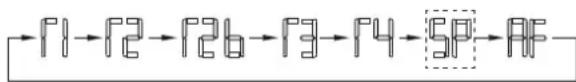
-
Press the COPY button.
- Press + or - to select the AF.

flowchart
graph LR
    F1 --> F2 --> F2b --> F3 --> F4 --> SP --> RF
- Press CONFIRM. The air conditioning unit will then start the fan for airflow automatic adjustment.
ON will flash when the fan is on during automatic airflow adjustment
CAUTION
- Do not adjust the dampers when automatic airflow adjustment is active.
After 3 to 6 minutes, the air conditioning unit stops operating once automatic airflow adjustment has finished.
!CAUTION
- If there is no change after airflow adjustment in the ventilation paths, be sure to reset automatic airflow adjustment.
- If there is no change to ventilation paths after airflow adjustment, contact your dealer, especially if this occurs after testing the outdoor unit or if the unit has been moved to a different location.
- Do not use automatic airflow adjustment with remote control, if you are using booster fans, outdoor air processing unit, or a HRV via duct.
- If the ventilation paths have been changed, reset airflow automatic adjustment as described from step 3 onwards.
Manual fan setting
The system can be set manually based on four static pressure settings.
Each setting has a low, medium and high speed range.
See fan performance curves on p.29 and p.30.
SP No. External static pressure parameters
| SP 1 0 – 40 Pa |
| SP 2 40 – 80 Pa |
| SP 3 80 – 120 Pa |
| SP 4 120 – 200 Pa |
When the system is OFF, perform the following steps using the wired controller.
- Press the COPY button and hold for 3 seconds.
- Press the + or - to select the required SP buttons.
flowchart
graph LR
    A["1"] --> B["2"]
    B --> C["3"]
    C --> D["4"]
    D --> E["5P"]
    E --> F["3F"]
- Press the CONFIRM button.
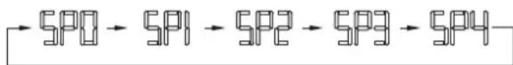
flowchart
graph LR
    A["SP0"] --> B["SP1"] --> C["SP2"] --> D["SP3"] --> E["SP4"]
- Press the CONFIRM button.
The external static pressure settings is now complete.
Electrical safety checks
After installation, confirm that all electrical wiring is installed in accordance with local and national requirements, and according to the Installation Manual.
Before test run
Check grounding work
Measure grounding resistance by visual detection and with grounding resistance tester. Grounding resistance must be less than 4Ω .
During test run
Check for electrical leakage
During the test run, use an electroprobe and multimeter to perform a comprehensive electrical leakage test.
If electrical leakage is detected, turn off the unit immediately and call a licensed electrician to find and resolve the cause of the leakage.

WARNING
Risk of electric shock
All wiring must comply with local and national electrical codes, and must be installed by a licensed electrician.
11. Test run
Before test run
A test run must be performed after the entire system has been completely installed. Confirm the following points before performing the test:
- Indoor and outdoor units are properly installed.
- Piping and wiring are properly connected.
- No obstacles near the inlet and outlet of the unit that might cause poor performance or product malfunction.
- Refrigeration system does not leak.
- Drainage system is unimpeded and draining to a safe location.
- Heating insulation is properly installed.
- Grounding wires are properly connected.
- Length of the piping and additional refrigerant stow capacity have been recorded.
- Power voltage is the correct voltage for the air conditioner.

CAUTION
Failure to perform the test run may result in unit damage, property damage, or personal injury.
Test run instructions
- Open both the liquid and gas stop valves.
- Turn on the main power switch and allow the unit to warm up.
- Set the air conditioner to COOL mode.
- For the indoor unit
a. Ensure the wired control and its buttons work properly.
b. Double check to see if the room temperature is being registered correctly.
c. Ensure the indicators on the wired control and the display panel on the indoor unit work properly.
d. Ensure the manual buttons on the indoor unit works properly.
e. Check to see that the drainage system is unimpeded and draining smoothly.
f. Ensure there is no vibration or abnormal noise during operation.
5. For the outdoor unit
a. Check to see if the refrigeration system is leaking.
b. Make sure there is no vibration or abnormal noise during operation.
c. Ensure the wind, noise, and water generated by the unit do not disturb your neighbours or pose a safety hazard.
6. Drainage test
a. Ensure the drainpipe flows smoothly. For installations in new buildings, you should perform this test before finishing the ceiling.
b. Remove the test cover. Add 2,000ml of water to the tank through the attached tube.
c. Turn on the main power switch and run the air conditioner in COOL mode.
d. Listen to the sound of the drain pump to see if it makes any unusual noises.
e. Check to see that the water is discharged. It may take up to one minute before the unit begins to drain, depending on the drainpipe.
f. Make sure that there are no leaks in any of the piping.
g. Stop the air conditioner. Turn off the main power switch and reinstall the test cover.
NOTE: If the unit malfunctions or does not operate according to your expectations, please refer to the Troubleshooting section of the Owner's manual before calling customer service.
12. Manual operations
Manual operations
This display panel on the indoor unit can be used to operate the unit in case the remote control has been misplaced or is out of batteries.
- MANUAL button: This button selects the mode in the following order: AUTO, FORCED COOL, OFF.
- FORCED COOL mode: In FORCED COOL mode, the Operation light flashes. The system will then turn to AUTO after it has cooled with a high wind speed for 30 minutes. The remote control will be disabled during this operation.
- OFF mode: When the panel is turned OFF, the unit turns off and the remote control is re-enabled.
Fig. 12.1
Error codes
natural_image
Pure electrical circuit lines without any symbols| Number Cause | The number of flashes per second | Timer indicator | Error code | |
| 1 Indoor EEPROM (Electrically Erasable Programmable Read-Only Memory) error 1 Off EH00 | ||||
| 2 Indoor and outdoor unit communication malfunction 2 Off EL01 | ||||
| 3 Indoor fan speed malfunction 4 Off EH03 | ||||
| 4 Indoor room temperature sensor error 6 Off EH60 | ||||
| 5 Evaporator coil temperature sensor error 6 Off EH61 | ||||
| 6 Refrigerant leak malfunction 8 Off ELOC | ||||
| 7 Water level alarm malfunction 13 Off EH0E | ||||
| 8 Dual indoor unit (twins model only) communication malfunction 9 Off EH12 | ||||
| 9 Outdoor unit malfunction | 14 Off EC0d | |||
| 10 | Communication error between indoor main board chips | 9 | Off | EH0b |
| 11 | Outdoor ambient temperature sensor error | 5 | Off | EC53 |
| 12 | Outdoor condenser pipe sensor error | 5 | Off | EC52 |
| 13 | Compressor discharge temperature sensor error | 5 | Off | EC54 |
| 14 | Outdoor IPM Module temperature sensor error | 5 Off EC55 | ||
| 15 | Communication error between master and slave unit (twins system) | 11 | Off | EL11 |
| 16 | Outdoor EEPROM (Electrically Erasable Programmable Read-Only Memory) error | 5 On | EC51 | |
| 17 | Outdoor fan speed (DC fan motor only) malfunction | 12 | Off | EC07 |
| 18 | Inverter module IPM protection | 7 | Flash | PC00 |
| 19 | High/Low voltage protection | 2 | Flash | PC01 |
| 20 | Compressor top overheating protection | 3 | Flash | PC02 |
| 21 | Outdoor high/low pressure protection | 4 | Flash | PC03 |
| 22 | Compressor drive error | 5 | Flash | PC04 |
| 23 | Compressor low pressure protection | 7 | Flash | PC03 |
| 24 | Outdoor IGBT sensor error | 8 | Flash | PC07 |
Notes
kaden irc
your perfect climate


- Installation Manual
- Important note
- Table of contents
- Safety precautions 4
- Accessories 6
- Installation summary 7
- Indoor unit installation 8
- Outdoor unit installation 16
- Drainpipe installation 19
- Refrigerant piping connection 21
- Leak testing and evacuation 25
- Wiring 27
- Electrical checks 34
- Test run 35
- Manual operations 36
- Safety precautions
- Read safety precautions before operation and installation
- WARNING
- AUTION
- Note about fluorinated gases
- REFRIGERANT
- Accessories
- Indoor unit installation
- Indoor unit parts
- Safety precautions
- DO NOT install unit in the following locations:
- Indoor unit installation instructions
- Step 1: Select installation location
- Step 2: Hang indoor unit
- Wood
- New concrete bricks
- Original concrete bricks
- Steel roof beam structure
- Step 3: Diagrammatic sketch for installing the main body
- Step 4: Duct and accessories installation
- Note
- Step 5: Motor and drain pump maintenance
- Pump maintenance
- Motor maintenance
- Disconnect-type installation
- Outdoor unit installation
- Outdoor unit installation instructions
- Step 2: Install outdoor unit
- Outdoor unit specifications
- Rows of series installation
- Drain joint installation
- Notes on drilling hole in wall
- Drainpipe installation
- Indoor drainpipe installation
- Note on drainpipe installation
- Drainage pump test procedure
- Refrigerant piping connection
- Note on pipe length and elevation
- Oil traps
- Refrigerant piping connection instructions
- CAUTION
- Step 1: Cut pipes
- Step 2: Remove burrs
- Step 3: Flare pipe ends
- Step 4: Connect pipes
- Note on minimum bend radius
- Leak testing and evacuation
- Leak, pressure test and evacuation
- Preparations and precautions
- Before performing evacuation
- Opening outdoor unit valves
- Note on adding refrigerant
- Wiring
- Take note of fuse specifications
- Choose the right cable size
- Power specifications
- Outdoor unit wiring
- Electrical requirement
- Preparing cable
- Selecting cable
- Signal wiring between outdoor and indoor units
- Indoor unit wiring
- Using the wire controller to set external static pressure
- !CAUTION
- Manual fan setting
- Electrical safety checks
- Before test run
- Check grounding work
- During test run
- Check for electrical leakage
- Risk of electric shock
- Test run
- Test run instructions
- For the outdoor unit
- Drainage test
- Manual operations
- Manual operations
- Error codes
- Notes
- kaden irc
Brand : Kaden
Model : KDI36
Category : Refrigerator