
VT-SHE904A - Radio Vitek - Free user manual and instructions
Find the device manual for free VT-SHE904A Vitek in PDF.

| Product Type | HD-TVI / AHD / 960H Digital Video Recorder |
| Video Inputs | 4 Channels (TVI/AHD/960H) |
| Video Compression | H.264 |
| Display & Recording Frame Rate | 120 fps @ 1080P / 720P / 960H / D1 / 2CIF / CIF |
| Audio Inputs / Output | 4 Line In (RCA) / 1 Line Out (RCA) |
| Alarm Inputs / Output | None (N/A) |
| Internal Storage | 1 SATA HDD (up to 6TB) |
| Video Outputs | 1 HDMI, 1 VGA |
| Network Interface | 1 x RJ-45 10/100/1000 Mbps Ethernet |
| Remote Viewing | Web browser (Windows, Linux, Mac OSX), iOS & Android apps |
| PTZ Control | CoC (Up the COAX) |
| Power Supply | DC 12V, 2A adapter; Input: 100~240VAC, 50/60Hz |
| Power Consumption | 4W max (without HDD) |
| Dimensions (W x H x D) | 10 x 1.85 x 7.25 inches (255.6 x 44 x 172.3 mm) |
| Weight | 3.3 lbs (1.5 kg) |
| Operating Temperature | 32°F ~ 104°F (0°C ~ 40°C) |
| Humidity | 10% ~ 90% (non-condensing) |
| Included Accessories | USB mouse, IR remote control with batteries, power adapter, power cable, screws, user manual on USB, quick guide |
| Key Features | Quick Search, motion detection (20x12 grid), panic record, pre/post recording, email notifications, backup player, HDD PC viewer |
| Cleaning & Maintenance | Wipe with a dry cloth; avoid water, paint thinner, or organic solvents |
| Safety Precautions | Keep away from humidity; ensure proper grounding; do not open cover; use only provided power adapter |
| Hard Drive Replacement | User-replaceable; 1 internal SATA HDD; see manual for instructions |
Frequently Asked Questions - VT-SHE904A Vitek
User questions about VT-SHE904A Vitek
0 question about this device. Answer the ones you know or ask your own.
Ask a new question about this device
Download the instructions for your Radio in PDF format for free! Find your manual VT-SHE904A - Vitek and take your electronic device back in hand. On this page are published all the documents necessary for the use of your device. VT-SHE904A by Vitek.
USER MANUAL VT-SHE904A Vitek
natural_image
Three black VITEK and SpireHD electronic devices with control buttons and ports (no visible text or symbols on the devices themselves)FEATURES
• Supports High Resolution HD-TVI, AHD, and 960H Cameras
• 4, 8, or 16 Video Inputs with 1 HDMI & 1 VGA Output (VT-SHE904A/VT-SHE908A) / 1 HDMI, 2 Spot Monitor, & 1 VGA Outputs (VT-SHP916A)
• H.264 Compression
• Realtime with up to 480fps Live Display & 480fps Recording (VT-SHP916A) / 240/240 (VT-SHE908A) / 120/120 (VT-SHE904A)
• Supports both Dynamic and Static IP Addresses
• 16 Audio In / 2 Audio Out (VT-SHP916A) / 4 Audio In / 1 Audio Out (VT-SHE904A/VT-SHE908A)
- 18 Alarm Inputs (16 +1 Panic & 1 Reset) 8 Outputs with 8 Relays (VT-SHP916A) / 4 Alarm Inputs with 1 Relays (VT-SHE908A)
- Remote Viewing over the Internet via Web Browser or LAN
- Up to Five internal 6TB HDD for up to 30TB of internal Storage (VT-SHP916A) / 2 internal HDD (VT-SHE908A) / 1 internal HDD (VT-SHE904A)
- 6TB Hard Drive Support
- Applications for iPhone, iPad, iTouch and Android Devices
- "Quick Search" Function for automatic review
• Mac OSX Client & CMS Central Management Software Included
• Automatic sending of Health & Event notifications via email
- Control locally via Front Panel Controls, USB Mouse or with the Included IR Remote control
• PTZ Control over RS-485 (VT-SHE908A & VT-SHP916A)
- Rack Mountable (VT-SHP916A)
Table of Contents
INTRODUCTION
4
4 Safety Instructions
5 What's Included
6 Remote Control at a Glance
7 Change Remote Control ID
VT-SHE-A
8
8 VT-SHE-A Overview
9 VT-SHE-A Specifications
10 VT-SHE-A Rear Panels
12 Replacing HDD
16 Basic Layout
17 Connecting to an External Device
VT-SHP916A
22
22 VT-SHP916A Overview
23 VT-SHP916A Specifications
24 VT-SHP916A Rear Panel
26 Replacing HDD
28 Basic Layout
29 Connecting to an External Device
MONITORING
36
36 Monitoring
38 Live Screen at a Glance
SYSTEM SETTING
45
45 To Move to the System Setup Menu
46 Camera Setting
51 Display Setting
56 Audio Setup
57 User Setting
59 Network Setup
62 System Setting
66 Storage
68 Event Setup
RECORD SETTING
76
76 To start the Record Setup Menu
77 Record Setup
SEARCH
81
81 To Move to the Search Menu while in Monitoring
81 To Move to the Search Menu while in Playback Mode
82 Search Settings
PLAY
85
85 If you Want to Play
ARCHIVING
88
88 To start the Archive Menu
WEB VIEWER
91
91 What is the Web Viewer?
93 Live Screen at a Glance
97 Search
99 Setup
MOBILE VIEWER
115
115 SPIRE DVR Smartphone App
ARCHIVE VIEWER
127
127 Getting Started with the Backup Player
129 Backup Player At a Glance
APPENDIX
132
132 Compatible HDD Specifications
133 Troubleshooting (FAQ)
Introduction
Safety Instructions
Vitek shall not have any responsibility for any accident or damage that may incur during the use of the product. For your safety, we provide the following instructions regarding installation, cleaning, assembly/disassembly of the product. Please read carefully, and comply with the instructions.
Before installation
Comply with the following instructions to prevent fire, explosion, system failure or electrical shock.
\~ Remove the power supply module before proceeding.
\~ Check the input voltage (AC100V-AC240V) to the power supply module before connecting it.
\~ Keep the product away from humidity.
\~ Ensure that all devices connected to the product are properly earth-grounded.
In operation mode
Comply with the following instructions to prevent fire, explosion, system failure or electric shock.
\~ If you need to open the cover, consult with an authorized Vitek service technician.
\~ Do not connect multiple devices to a single power outlet.
\~ Keep the product away from dust or combustible substances (ex: propane gas).
\~ Do not touch product with wet hands.
\~ Do not insert anything into the vent of the ventilation system.
\~ Do not apply excessive force when unplugging the power cord.
Disassembly & Cleaning
\~ When cleaning the surface, use a dry cloth.
\~ Do not wipe the product using water, paint thinner or organic solvents.
\~ Do not dismantle, repair or modify the product on your own.
During installation
To prevent an accident or physical injury, please comply with the following:
\~ Secure at least 6 inches of distance between cooling fan and wall for a proper ventilation.
\~ Install the product on a flat surface.
\~ Keep product away from direct sunlight or excessive temperature.
While in use
\~ Do not apply force or shake product while using it.
What's included

natural_image
3D rendered image of a gray computer mouse (no text or symbols visible)Mouse x1
natural_image
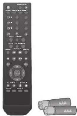
Black remote control with black buttons and two USB drive units beside it (no visible text or symbols)Remote Control x1 & Batteries (AAA x2)
natural_image
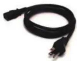
Black cable with two terminal leads, no visible text or symbolsPower Cable x1

natural_image
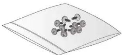
Black rectangular electronic device with cable and connector, no visible text or symbolsDC 12V Adaptor x1 Screws

natural_image
Illustration of a black cable with two connectors (no text or symbols)Conversion adaptor (VT-SHP916A)
chemical
Molecular structure diagram showing a central atom bonded to multiple surrounding atoms, likely representing a molecular model or cluster.
natural_image
Green VITEK USB flash drive with a circular logo, no visible text or symbols on the device itself.User Manual on USB

natural_image
Simple line drawing of a stack of papers or documents (no text or symbols)Quick Guide
SpireHD Series Remote
SR-SERIES Remote Control At a Glance

Change the remote control ID
The remote control will only function if the Remote Control ID matches with that specified on the DVR.
If multiple DVRs are installed at one location and you would like to have just a single remote control, use the ID button to set the remote control ID. Only the ID-matching DVR can be controlled.
- From
- Press the [ID] button on the remote control. The default remote control ID is 00.
- Use the number buttons to provide a two-digit ID. If you want to enter 01, for instance, enter the number 0 and 1 in sequence. To check if the remote control ID is set properly, manipulate the remote control and see if the DVR responds.
- To reset the ID to 00, press and hold the [ID] button.
VT-SHE-A Overview

natural_image
Exterior view of a VITEK and SpireHD home devices with labeled ports (PWR, REC, NET, ALM) and HDMI branding (no additional text or symbols visible)VT-SHE-A Series
SpireHD Series Realtime HD 4 & 8 Channel HD-TVI / AHD / 960H Digital Video Recorders
VT-SHE-A Key Features
• Supports High Resolution HD-TVI, AHD, and 960H Cameras
• 4 or 8 Video Inputs with 1 HDMI and 1 VGA output
• H.264 Compression
• Realtime with up to 240fps Live Display & Recording (VT-SHE908A) / 120fps Live Display & Recording (VT-SHE904A)
• 4 Audio Inputs / 1 Audio Output
• Supports both Dynamic and Static IP Addresses
• 4 Alarm Inputs with 1 Relays (VT-SHE908A)
- Remote Viewing over the Internet via Web Browser or LAN
- Up to Two internal 6TB HDD for up to 12TB of internal Storage (VT-SHE908A) / Up to one internal 6TB HDD for up to 6TB of internal Storage (VT-SHE904A)
• Supports 6TB Hard Drives
• Applications for iPhone, iPad, iTouch and Android Devices
- "Quick Search" Function for automatic review
• Mac OSX Client & CMS Central Management Software Included
• Automatic sending of Health & Event notifications via email
• Control locally via USB Mouse or with the Included IR Remote control
• PTZ Control over RS-485 (VT-SHE908A)
Detailed Specifications VT-SHE904A VT-SHE908A
| Video Inputs | 4 Channels (TVI / AHD / 960H) | 8 Channels (TVI / AHD / 960H) |
| Video Compression | H.264 | H.264 |
| FPS (Display & Recording) | 120 / 120 @ 1080P / 720P / 960H / D1 / 2CIF / CIF | 240 / 240 @ 1080P / 720P / 960H / D1 / 2CIF / CIF |
| FPS (Playback) | Up to 30FPS @ 1080p / Up to 120FPS @ 2CIF | Up to 30FPS @ 1080p / Up to 120FPS @ 2CIF |
| Operating System | Linux | |
| Video Output | VGA / HDMI | |
| Dual Monitor Support | NO | |
| Spit-Screen | Live: 1, 4, SEQ / Playback: 1, 4 | Live: 1,4,6,8,9, SEQ / Playback: 1, 4, 9 |
| Audio In/Out | 4 Line In (RCA) / 1 Line Out (RCA) | |
| Alarm In/Out | N/A | 4 Alarm Inputs + 1 Relay |
| Internal Storage | 1 Internal HDD (SATA) | 2 Internal HDD (SATA) |
| On-Board RAID | N/A | |
| External Storage | NAS (Backup to FTP Server) | |
| Archive | USB Device & Network | |
| USB Port | 2 Ports (2 Front) | 3 Ports (2 Front + 1 Rear) |
| System Control | USB Mouse, Included IR Remote Control | |
| Network | TCP/IP, HTTP, DHCP (DDNS) | |
| RJ-45 Ethernet Port | 1x - 10/100/1000Mbps | |
| Auto Port Forwarding | YES | |
| Search | Calendar, Time, Panorama (thumbnail), Event | |
| PTZ Control | CoC (Up the COAX) | |
| Recording Resolution Setting | Individual resolution settings for each camera (CIF, 2CIF, D1, 960H, 720p, 1080P) | |
| Recording Quality Control | 5 Levels (Lowest/Low/Standard/High/Highest) | |
| Recording Modes | By hour, by day, by recording mode, By alarm, By Ch | |
| Panic Record | Overrides all other recording settings to provide the best quality recording | |
| Pre-recording | Max. 15 seconds | |
| Post-recording | Max. 180 seconds | |
| Motion Detection | Adjustable 20x12 Grid with 10 Steps Sensitivity Level | |
| Player | Backup player, and HDD PC Viewer | |
| Remote Viewing | YES (Windows®, Linux, Mac OSX®) | |
| E-mail notification | E-mails to specific users to notify events | |
| System Configuration | Full setup configuration over network | |
| Bandwidth limit | YES: Adjustable by User | |
| Two-Way Audio | YES | |
| Power | 12V Adaptor, 2A, 100~240VAC, 50~60Hz | 12V Adaptor, 3.3A, 100~240VAC, 50~60Hz |
| Power Consumption | 4W max. without HDD | 5W max. without HDD |
| Operating Temperature | 32° ~ 104°F (0° ~ 40°C) | |
| Humidity | 10 ~ 90% NC | |
| Case Form Factor | 1U | |
| Dimensions (W x H x D) | 10" x 1.85" x 7.25" (255.6 x 44 x 172.3mm) | 12" x 1.85" x 12.25" (305 x 44 x 298mm) |
| Weight | 3.3 lbs. (1.5kg) | 6.85 lbs. (3.1kg) |
VT-SHE-A Overview
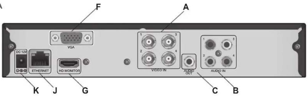
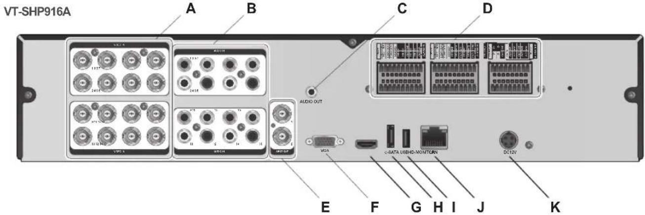
VT-SHE-A Rear Panels
VT-SHE904A
VT-SHE908A
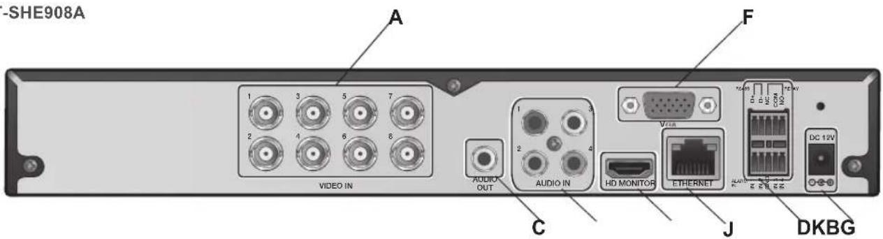
No. Name Description
| A | VIDEO IN Video input terminals for Analpg/TVI/AHD cameras. | |
| B | AUDIO IN Audio input terminals. | |
| C | AUDIO OUT Port for speaker connection. | |
| D | ALARM IN/OUT RS485 Alarm input/output terminals. | |
| E | SPOT Analog Spot Video Output | |
| F | VGA VGA monitor video output port. | |
| G | HDMI HDMI (HD monitor) video output port | |
| H | eSATA External SATA Port | |
| I | USB USB Input | |
| J | ETHERNET Network port for connection to the Internet, router or hub. | |
| K | POWER Power Input | |
VT-SHE-A Installation
Replacing HDD
When a hard drive is full or problematic, it is possible to replace it yourself.
4-Channel Model
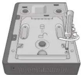
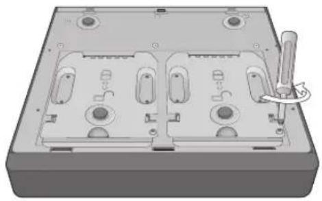
- Remove the screw from the bracket on the bottom of the DVR.
natural_image
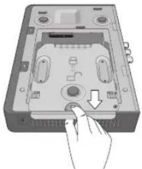
3D rendering of a mechanical device casing with mounting holes and a handle (no visible text or symbols)- Hold the HDD bracket with your finger as shown in the figure and pull it to separate it from the DVR.
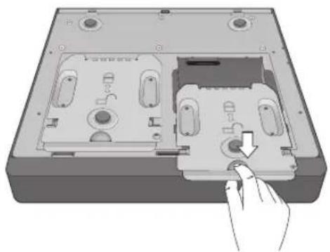
natural_image
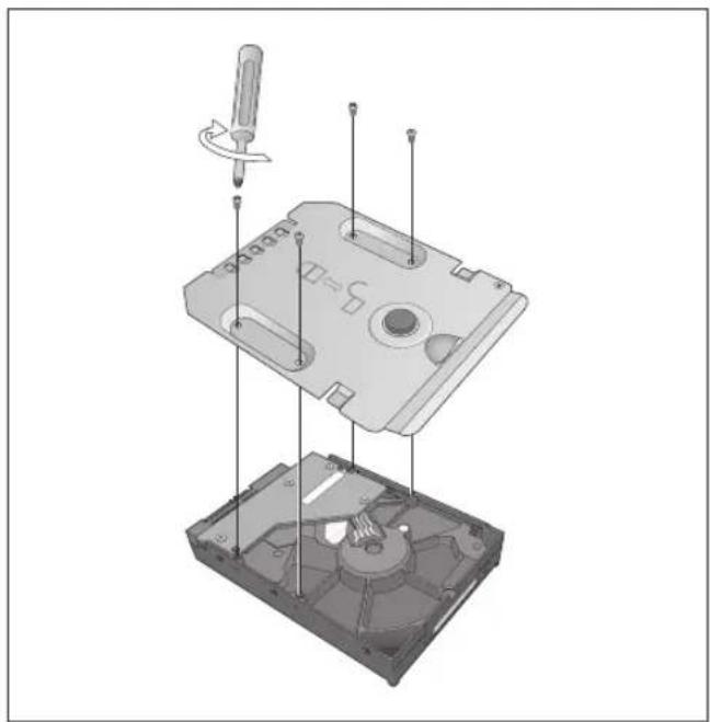
Illustration of a hand inserting a CD into a device casing (no text or symbols visible)- Install the HDD to the bracket (see figure).
When installing the HDD, make sure to install in the correct direction.
natural_image
Exploded view diagram of a mechanical device showing internal components and a screwdriver (no text or labels)- Insert the bracket back into the DVR.

natural_image
Hand inserting a CD into a device casing (no text or symbols visible)- Secure the bracket by fastening the screw.

natural_image
3D rendering of a computer case with a screwdriver inserted, showing internal components and mounting holes (no text or symbols)VT-SHE-A Installation
8-Channel Model
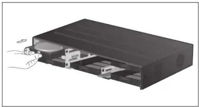
- Remove the screw from each bracket on the bottom of the DVR.
natural_image
3D rendering of a mechanical housing with multiple ports and a tool inserted (no text or symbols visible)- Hold the HDD bracket with your finger as shown in the figure and pull it to separate it from the DVR.
natural_image
Illustration of a computer case with a hand pointing to a component, showing internal components and a downward arrow (no text or symbols)- Install the HDD to the bracket (see figure)
When installing the HDD, make sure to install in the correct direction.

natural_image
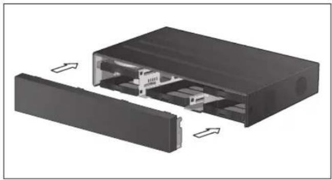
Exploded view diagram of a floppy disk assembly with screwdriver and internal components (no text or labels)- Insert the bracket back into the DVR.

natural_image
Diagram of a computer case with an open rear panel and a hand inserting a button (no text or symbols visible)- Secure the bracket by fastening the screw.

natural_image
3D rendering of a mechanical housing with internal compartments and a screwdriver inserted (no text or symbols visible)VT-SHE-A Installation
Basic Layout
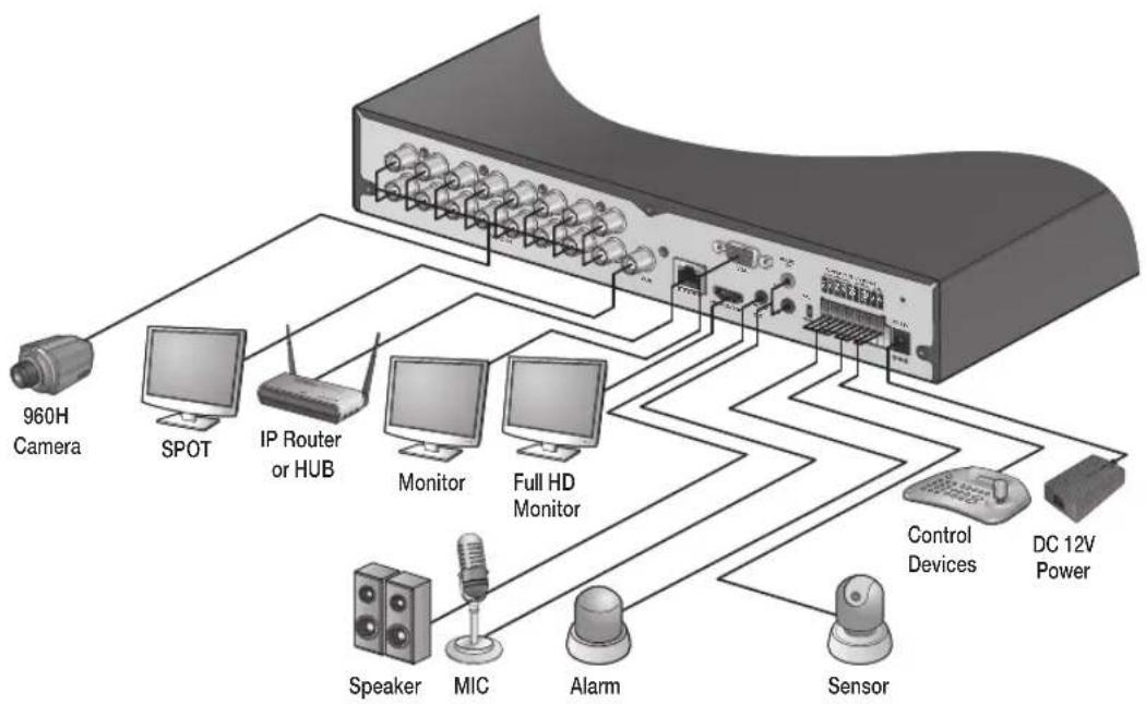
flowchart
graph TD
    A["960H Camera"] --> B["SPOT"]
    B --> C["IP Router or HUB"]
    C --> D["Monitor"]
    C --> E["Full HD Monitor"]
    D --> F["Control Devices"]
    E --> G["DC 12V Power"]
    F --> H["Sensor"]
    G --> H
    I["Speaker"] --> J["MIC"]
    K["Alarm"] --> L["Sensor"]
- Cable quality and distance can directly effect the video quality. it is recommended to consult an authorized installer when installing the DVR.
Connecting to an external device
Connecting to a Monitor
This product supports 1080p 60 Hz HDMI monitors and regular monitors that support DVI and VGA inputs. Connect an HDMI cable to the port on the product's rear bottom, or connect an HDMI-DVI converter cable to connect a DVI monitor. Or, use VGA cable to connect the product with a VGA monitor.
Power Connection
Plug the provided DC 12V adaptor in the rear power port of the DVR.
- For stable operation of the product, it is recommended to use the provided adapter. (12V, 5A)
• Make connection when the power is not applied yet. - Arrange the cables and be careful not to peel off the cable coating.
- Do not place the power cord under the carpet or rug. The power cord is usually earth-grounded. However, even if it's not earth-grounded, do not modify it on your own for earth-grounding.
- Do not plug multiple devices into single power outlet.
- For stability, this product provides two separate adaptors and two corresponding AC cords by factory default. Make sure all cables are connected properly.

Alarm I/O Connection (VT-SHE908A)
To connect the alarm input signal
Connect the signal line of an alarm input device to the rear [ALARM IN] port.
- Push the Alarm In and [GND] terminals' top side (orange color) with a sharp tipped tool such as screw driver.
- While pushing, insert one end of alarm signal cable into the hole of Alarm In terminal.
- While pushing, insert one end of ground cable into the hole of [GND] terminal.
VT-SHE-A Installation
- Check to be sure the cable has been inserted properly-- stop pushing and gently pull the cable to make sure it is secure. To disconnect a cable, push the top side of the terminal (orange color) and pull out the cable.

To connect the alarm output signal
Connect the signal cable of the alarm output device to the [RELAY] terminal on the product's rear side.
- Push the [NO]/[NC]/[COM] terminal's top side (orange color) with a sharp tipped tool such as screw driver.
- While pushing, insert one end of alarm signal cable into the desired terminal of [NO] or [NC].
NO(Normal Open) : Normally Open but switches to Closed if an alarm out occurs.
COM : Insert the grounding wire.
NC(Normal Closed) : Normally Closed but switches to Open if an alarm out occurs.
- Insert the ground signal wire into the hole of the [COM] port.
- Check to be sure the cable has been inserted properly-- stop pushing and gently pull the cable to make sure it is secure. To disconnect a cable, push the top side of the terminal (orange color) and pull out the cable.
Communication Port (VT-SHE908A)

RS-485 Connection
Connect a PTZ Camera or Keyboard Controller.
After connecting the control device, be sure to match the connection settings between the DVR and the device.
To change communication settings see
- Connect the positive (+) transmission signal cable of the PTZ camera/keyboard controller to the RS-485 [D+] communication port on the DVR's rear panel.
- Connect the negative (-) transmission signal cable of the PTZ camera/keyboard controller to the RS-485 [D-] communication port on the DVR's rear panel.
For RS-485 communication configuration, refer to the user's manual of the applicable PTZ camera or keyboard controller.
Audio Device Connection
Connect an audio input device such as a microphone to the rear Audio In port; connect an audio output device such as an amplifi ed speaker to the Audio Out port.
Storage and Mouse Connection
USB Device
You can connect and use USB storage devices for backup of recorded video, saving snapshots, fi rmware updating, importing/exporting user confi gurations. In addition, the DVR will accept a USB mouse.
- If you need to connect a USB HDD with a high power consumption, it is recommended to use a separate power source for that HDD.
20GB file size limit for backups
VT-SHE-A Installation
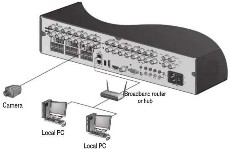
Network Connection
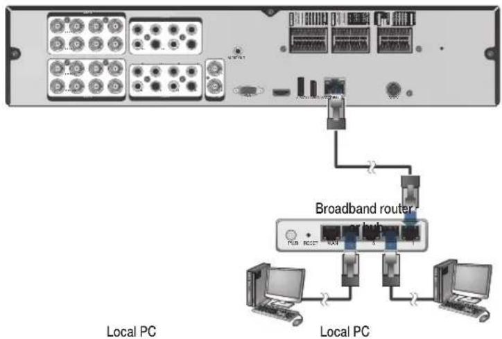
PC Connection - Local Network
You can connect the DVR to a PC in the same local area network.
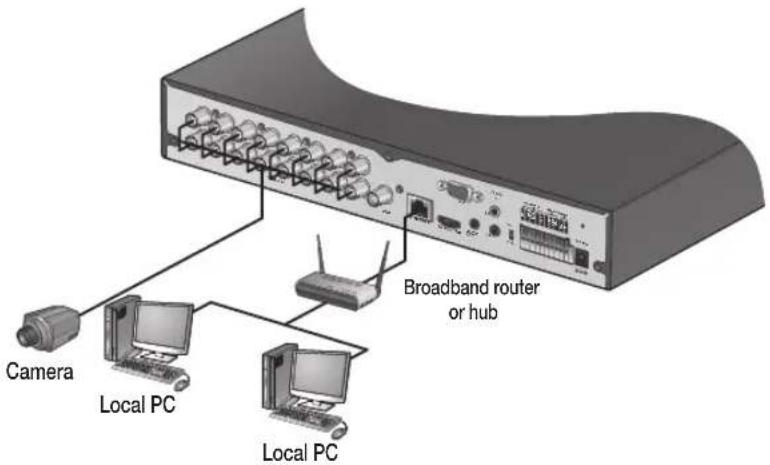
- Connect a CAT-5 network cable to the DVR's [ETHERNET] port on the rear panel to a router or hub.
- Connect a local PC to the same router or hub.
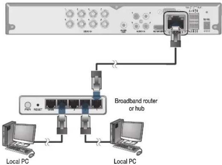
- Enter the DVR's IP address in the Web browser in the format of: "http://IP address:Web service port" (Ex : http://192.168.0.23:8080) The web service port is set to 8080 by default. From the Network Setup screen, you can change the port number.
If using the dedicated PC S/W, refer to the user manual of the program.
- Enter the DVR's Username and Password to log in. Factory default: ADMIN / 1234.
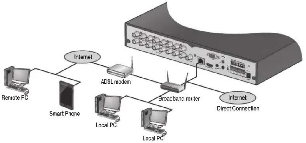
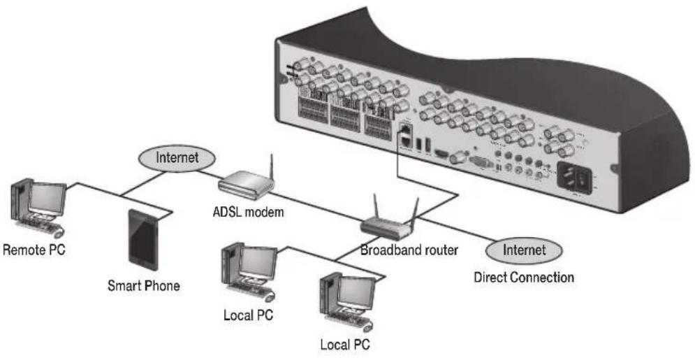
PC Connection - Remote Network
You can connect to the DVR from a remote PC or mobile device.
- Connect a CAT-5 network cable to the DVR's [ETHERNET] port on the rear panel to a router or hub.
flowchart
graph TD
    A["Remote PC"] --> B["Smart Phone"]
    B --> C["ADSL modem"]
    C --> D["Broadband router"]
    D --> E["Internet Direct Connection"]
    D --> F["Internet"]
    C --> G["Local PC"]
    C --> H["Local PC"]
- Connect the [WAN(UPLINK)] port of the router directly to the fixed IP LAN cable, or connect it to the ADSL modem.

flowchart
graph TD
    A["ADSL modem"] --> B["Broadband router"]
    B --> C["Local PC"]
    B --> D["Internet 1"]
    B --> E["Internet 2"]
    B --> F["Internet 3"]
    B --> G["Internet 4"]
    B --> H["Internet 5"]
    B --> I["Internet 6"]
    B --> J["Internet 7"]
    B --> K["Internet 8"]
    B --> L["Internet 9"]
    B --> M["Internet 10"]
    style A fill:#f9f,stroke:#333
    style B fill:#ccf,stroke:#333
    style C fill:#cfc,stroke:#333
    style D fill:#fcc,stroke:#333
    style E fill:#cff,stroke:#333
    style F fill:#ffc,stroke:#333
    style G fill:#cfc,stroke:#333
    style H fill:#fcc,stroke:#333
    style I fill:#cfc,stroke:#333
    style J fill:#fcc,stroke:#333
    style K fill:#cfc,stroke:#333
    style L fill:#fcc,stroke:#333
- If using a router, make sure BOTH the Web Service Port and RTSP Port have been port forwarded.
- You can remotely access your DVR in the following ways:
a. The DVR's MAC address
b. The DVR's DDNS Host Name aka DVR NAME
c. The external IP address of the network
NOTE: See page 74 for more detail
VT-SHP916A Overview

VT-SHP916A
SpireHD Series Realtime HD 16 Channel HD-TVI / AHD / 960H Digital Video Recorder
VT-SHP916A Key Features
• Supports High Resolution HD-TVI, AHD, and 960H Cameras
• 16 Video Inputs with 1 HDMI, 2 Spot, and 1 VGA output
• H.264 Compression
• Realtime with up to 480fps Live Display & 480fps Recording
• Supports both Dynamic and Static IP Addresses
• 18 Alarm Inputs (16 +1 Panic & 1 Reset) 8 Outputs with 8 Relays
• 16 Audio In / 1 Audio Out
- Remote Viewing over the Internet via Web Browser or LAN
• Supports Five internal Hard Drives for up to 30TB of internal Storage (5 x 6TB HDD)
- RAID 5 (block level HDD striping with distributed parity) & RAID 1 (HDD Mirroring) for data integrity
• Supports 6TB Hard Drives
• Applications for iPhone, iPad, iTouch and Android Devices
- "Quick Search" Function for automatic review
- Gigabit Ethernet
• Mac OSX Client & Central Management Software (CMS) Included
• Automatic sending of Health & Event notifications via email
• Control locally via Front Panel Controls, USB Mouse or with the Included IR Remote control
• PTZ Control over RS-485
- Rack Mountable with included Rack Ears
Detailed Specifications
| Video Inputs | 16 Channels (TVI / AHD / 960H) |
| Video Compression | H.264 |
| FPS (Display & Recording) | 480 / 480 @ 1080P / 720P / 960H / D1 / 2CIF / CIF |
| FPS (Playback) | 4div: Up to 120FPS @ 1920x1080 / Up to 480FPS @ CIF |
| Operating System | Linux |
| Video Output | VGA / HDMI / 2x Spot BNC |
| Dual Monitor Support | YES |
| Spit-Screen | Live: 1, 4,6,8,9,16 SEQ / Playback: 1, 4,6,8,9,16 |
| Audio In/Out | 16 Line In (RCA) / 1 Line Out (RCA) |
| Alarm In/Out | 18 Alarm Inputs (16 +1 Panic & 1 Reset) 8 Outputs with 8 Relays |
| Internal Storage | 5 Internal HDD's (SATA) |
| On-Board RAID | YES |
| External Storage | eSATA / NAS (Backup to FTP Server) |
| Archive | USB Device & Network |
| USB Port | 3 Ports (2 Front + 1 Rear) |
| System Control | Front Panel, USB Mouse, Included IR Remote Control, or Keyboard controller |
| Network | TCP/IP, HTTP, DHCP (DDNS) |
| RJ-45 Ethernet Port | 1x - 10/100/1000Mbps |
| Auto Port Forwarding | YES |
| Search | Calendar, Time, Panorama (thumbnail), Event |
| PTZ Control | CoC (Up the COAX) / 2x RS485 & 1x RS232 |
| Recording Resolution Setting | Individual resolution settings for each camera (CIF, 2CIF, D1, 960H, 720p, 1080P) |
| Recording Quality Control | 5 Levels (Lowest/Low/Standard/High/Highest) |
| Recording Modes | By hour, by day, by recording mode, By alarm, By Channel |
| Panic Record | Overrides all other recording settings to provide the best quality recording |
| Pre-recording | Max. 15 seconds |
| Post-recording | Max. 180 seconds |
| Motion Detection | Adjustable 20x12 Grid with 10 Steps Sensitivity Level |
| Player | Backup player and HDD PC Viewer |
| Remote Viewing | YES (Windows®, Linux, Mac OSX®) |
| E-mail notification | E-mails to specific users to notify events |
| System Configuration | Full setup configuration over network |
| Bandwidth limit | YES: Adjustable by User |
| Two-Way Audio | YES |
| Power | 12V Adaptor, 6.67A, 100~220VAC, 50~60Hz |
| Power Consumption | 42W max. without HDD |
| Operating Temperature | 32° ~ 104°F (0° ~ 40°C) |
| Humidity | 10 ~ 90% NC |
| Case Form Factor | 2U |
| Dimensions (W x H x D) | 16.93" x 3.48" x 14.45" (430 x 88.4 x 367mm) |
| Weight | 12.0 lbs (5.4kg) |
VT-SHP916A Overview
VT-SHP916A
No. Name Description
| A | VIDEO IN Video input terminals for Analpg/TVI/AHD cameras. | |
| B | AUDIO IN Audio input terminals. | |
| C | AUDIO OUT Port for speaker connection. | |
| D | ALARM IN/OUT RS485 Alarm input/output terminals. | |
| E | SPOT Analog Spot Video Output | |
| F | VGA VGA monitor video output port. | |
| G | HDMI HDMI (HD monitor) video output port | |
| H | eSATA External SATA Port | |
| I | USB USB Input | |
| J | ETHERNET Network port for connection to the Internet, router or hub. | |
| K | POWER Power Input | |
VT-SHP916A Installation
Replacing HDD
When a HDD is full or problematic, it is possible to replace it yourself.
Replacing All 5 Hard Drives
Below illustrations are based on the 16-channel model.
- Remove the 2 screws on both ends of DVR.
-
Pull the front faceplate of the unit forward to separate it.
-
Hold the middle section of HDD bracket's handle with index finger and pull it forward while supporting the bracket handle with your thumb and middle finger as shown in the illustration.

natural_image
Diagram of an open electronic device showing internal components and housing (no text or symbols)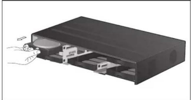
natural_image
Illustration of a device internal structure with a hand inserting a component (no text or symbols visible)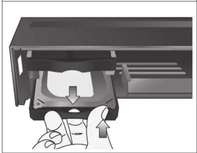
natural_image
Hand inserting a CD into a drive into a memory compartment (no text or symbols visible)- Once the HDD bracket is separated from the main unit, remove 4 screws on both ends of HDD bracket to separate the HDD from the bracket.
- Install a new HDD and fasten the 4 screws back to both ends of the bracket.
When installing HDD, make sure to install in the correct direction.

- Push the bracket (with new hard drive installed) back into the main unit until it is completely inserted.
natural_image
Diagram of a computer drive showing internal components and a hand interacting with the lid (no text or symbols present)- Assemble the front panel back to the unit.
- Fasten the 2 screws on both ends of the main unit.
natural_image
Diagram of an open electronic device showing internal components and external casing (no text or symbols)VT-SHP916A Installation
Basic Layout

flowchart
graph TD
    A["POS"] --> B["ATM"]
    B --> C["Access Controller"]
    C --> D["Sensor"]
    D --> E["IP Router or HUB"]
    E --> F["Mouse"]
    F --> G["sSATA Storage"]
    G --> H["Full HD (RGB) Monitor"]
    G --> I["AUX SPOT Monitor"]
    G --> J["VGA Monitor"]
    G --> K["Speaker"]
    L["960H Camera"] --> M["Control Devices"]
    M --> N["Alarm"]
    N --> O["Microphone"]
Cable quality and distance can directly effect the video quality. it is recommended to consult an authorized installer when installing the DVR.
Connecting to an external device
Connecting to the monitor
This product supports 1080p 60 Hz HDMI monitors and regular monitors that support DVI and VGA inputs. Connect an HDMI cable to the port on the product's rear bottom, or connect an HDMI-DVI converter cable to connect a DVI monitor. Or, use VGA cable to connect the product with a VGA monitor.
Power Connection
Plug the provided power cord to the rear power port of the DVR.
- Do not place the power cord under the carpet or rug. The power cord is usually earth-grounded. However, even if it's not earth-grounded, do never modify it on your own for earth-grounding.
- Do not insert multiple devices in a single power socket. Otherwise, it may cause a power overload.

VT-SHP916A Installation
Alarm I/O Connection
To connect the alarm input signal

natural_image
Back panel of a network equipment rack with multiple ports and connectors (no visible text or labels)Connect the signal line of an alarm input device such as sensor to the rear [ALARM IN] port.
- Loosen the screws on both the alarm input port and [GND] port of the provided terminal block plug.
- Insert one end of alarm signal cable through the [AO1] or [AO8] terminal hole below the screw hole, and then fasten the screw.
- Insert the ground signal wire into the hole of the [GND] port (shown also below the screw), and tighten the screw.
- To check proper insertion of cable, stop pushing and gently pull the cable and test whether it disconnects. To disconnect a cable, push the bottom side of the terminal and pull out the cable.
To connect the alarm output signal
Connect the signal line of an alarm output device to the rear [RELAY] port.
Loosen the screws on the [NO] and [NC] ports and the [COM] port of the provided terminal block plug.
2. Insert the alarm signal wire into the hole of the [NO] or [NC] input port (shown below the screw), and tighten the screw. Check the relay output type of Normal Open or Normal Close before selecting a proper type (NO or NC).
NO(Normal Open) : Normally Open but switches to Closed if an alarm out occurs.
COM : Insert the grounding wire.
NC(Normal Close) : Normally Closed but switches to Open if an alarm out occurs.
- Insert the ground signal wire into the hole of the [COM] port (shown also below the screw), and tighten the screw.
Or, you can connect the signal cable of the alarm output device to the [ALARM OUT] port on the rear side.
Loosen the screws on the [AO1] and [AO8] ports and the [GND] port of the provided terminal block plug.
2. Insert the alarm signal wire into the hole of the [AO1] or [AO8] input port (shown below the screw), and tighten the screw.
Check the relay output type of Normal Open or Normal Close before selecting a proper type (NO or NC).
3. Insert the ground signal wire into the hole of the [GND] port (shown also below the screw), and tighten the screw.
4. To check proper insertion of cable, stop pushing and gently pull the cable and test whether it disconnects. To disconnect a cable, push the bottom side of the terminal and pull out the cable.
5. Install the wire-connected terminal block in the rear port.
Communication Port

RS-485 Connection
Connect a PTZ Camera or Keyboard Controller.
You can connect a text-in device such as POS or ATM (future firmware release).
After connecting the control device, be sure to match the connection settings between DVR and device.
Make communication settings in
- Connect the positive (+) transmission signal cable of the PTZ camera/keyboard controller to the RS-485 [D+] communication port on the DVR's rear panel..
- Connect the negative (-) transmission signal cable of the PTZ camera/keyboard controller to the RS-485 [D-] communication port on the DVR's rear panel.
- Connect the [GND] port of the terminal block plug and the [GND] port of the keyboard controller.
For RS-485 communication configuration, refer to the user's manual of the applicable PTZ camera or keyboard controller.
RS-232 Connection
You can connect PTZ cameras, POS or ATM devices (future firmware release).
For connection of the text-in device, refer to the user manual of the text-in device.
Audio Device Connection
Connect an audio input device such as a microphone to the rear Audio In port; connect an audio output device such as an amplified speaker to the Audio Out port.
VT-SHP916A Installation
Storage and Mouse Connection
eSATA Storage

If the internal storage space is insufficient, you can extend your storage capacity by adding an eSATA storage device to the rear eSATA port.
- Using devices other than the recommended eSATA products may cause serious problem.
USB Device
You can connect and use USB storage devices for backup of recorded video, saving snapshots, firmware updating, importing/exporting user configurations. Also, USB mouse can be connected for DVR manipulations.
- If you need to connect a USB HDD with a high power consumption, it is recommended to use a separate power source for that HDD.
√ 20GB file size limit for backups
Network Connection
PC connection in the local network
You can connect the DVR to a PC in the same local area network.
- Connect the [WAN(UPLINK)] port in the rear panel to the router or hub.
The LAN (DOWN LINK) port is only for a dedicated backup network device. (Do not connect devices to this port.)
- Connect the local PC to the same router or hub.
- Enter the address in the Web browser of your PC in the format of: "http://IP address:Web service port" (Ex : http://192.168.0.23:8080) The web service port is set to 8080 by default. From the Network Setup screen, you can change the port number.
If using the dedicated PC S/W, refer to the user manual of the program.
- Enter the DVR's username and Password to log in. Factory default is ADMIN / 1234
VT-SHP916A Installation
PC connection from a remote network
You can connect DVR to a PC or mobile device in the same remote network and control or manipulate it on the monitor of the PC or mobile device.
flowchart
graph TD
    A["Remote PC"] --> B["Smart Phone"]
    B --> C["ADSL modem"]
    C --> D["Broadband router"]
    D --> E["Direct Connection"]
    C --> F["Local PC"]
    D --> G["Local PC"]
    C --> H["Internet"]
    D --> I["Internet"]
    style A fill:#f9f,stroke:#333
    style B fill:#ccf,stroke:#333
    style C fill:#cfc,stroke:#333
    style D fill:#fcc,stroke:#333
    style E fill:#ffc,stroke:#333
    style F fill:#cff,stroke:#333
    style G fill:#ffc,stroke:#333
    style H fill:#cfc,stroke:#333
- Connect the [WAN(UPLINK)] port in the rear panel to the router.
The LAN (DOWN LINK) port is reserved and only for servicing and development. (Do not connect devices to this port.)

- Connect the [WAN(UPLINK)] port of the router directly to the fixed IP LAN cable, or connect it to the ADSL modem.
- If using the router, set the port forwarding and enter the DDNS address in the address bar (web browser) of the remote PC, or of the dedicated software program or mobile phone.
For the IP and DDNS address settings, refer to "Network Setup". (page 46)
- If the MAC address of the DVR is 00-11-5F-12-34-56 and the web port number is 8080, enter "http://00115f123456.dvrlink.net:8080" in the address bar of the web browser.
If you have renamed DDNS as "mydvr", you can make network connection at http://mydvr.dvrlink.net:8080.
Notes
Notes
Monitoring
START
- Connect the 110V power input to the rear panel of the DVR.
- The logo screen appears several seconds after the front LED turns on.
- When the booting process is completed, the login screen appears.
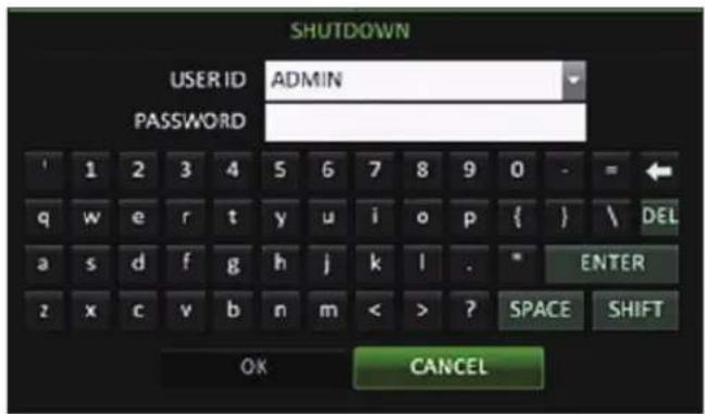
Log In
- When the system starts, the login screen appears.
- Select a user and provide the password. The default USER ID is: "ADMIN" and the PASSWORD is: "1234".
- Click
.
- For safe and secure use of the product, change the password after purchasing.

Log Out
To prevent unauthorized access, it is recommended to log out when you leave the screen.
- In the live monitoring screen, click
- While logged out, Search / Backup / System Settings / Record Settings / Exit menus are restricted.
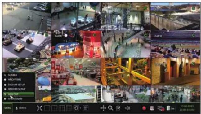
System Shutdown
- In the monitoring screen, click
- If you turn off the system in an abnormal manner such as removing the power cord while the system is in operation, the disk can be damaged, causing data loss and shortened life cycle of the disk.
Shutdown turns off Disk and Operations. The DVR will ask to disconnect power to the unit (on the SRP, turn the power switch next to the 110 power cord input to OFF)
Monitoring
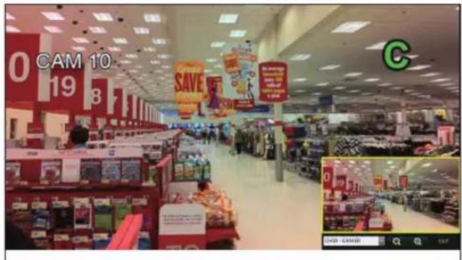
Live Screen At a Glance
The live screen largely consists of three components: video window, status bar and timeline.
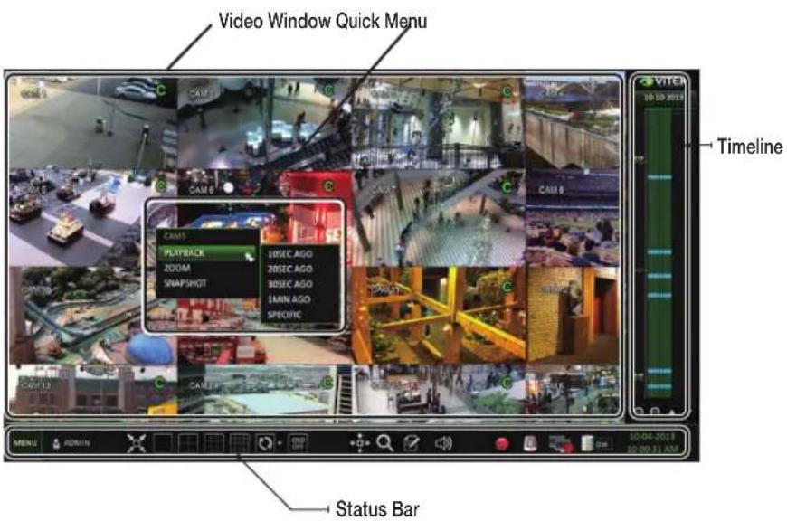
Video Window
Icons used in the video window.
| Item Description | ||
| Camera ID | CAM1 | Show the camera ID. |
| Record Mode Icons | Displayed if an event recording is reserved. | |
| C | Continuous Recording. | |
| A | Alarm Recording. | |
| M | Motion Recording. | |
| P | Panic (Emergency) Recording. | |
| Audio I/O Icons | Audio Output | |
| Motion Detection Icon | Motion is detected by the connected camera. | |
Status Bar
Press the [▼] button on the remote control, or place the mouse in the lower area of the screen to display the status bar.
| Item Description | ||
| Menu Button | [3702] | Allows access to the DVR's menu system |
| User ID |  | Show the ID of the currently logged in user |
| Screen Control Buttons |  | Edit the screen layout to show the status bar and timeline at all times or only when the mouse cursor hovers on the status bar/timeline. |
 | Select various display modes | |
| [3208] | Select Auto Sequence Mode. | |
 | Display or hide the OSD menu on the screen. | |
| PTZ |  | Launches the PTZ control screen. |
| Zoom |  | Digital Zoom. |
| Quick Log |  | Displays the log list of the recent recording events. |
| Audio Channel Selection Button |  | Select the audio input to listen to. |
| Panic Record |  | Start/stop panic recording. |
| Alarm Indicator |  | Tums on if a predetermined alarm event occurs. |
| Network Connection Status |  | Click this to view the current users remotely logged into the DVR, and to check the network connection status. For more information, refer to "Network Setup". (page 43) |
| Disk Space |  | If you have set the disk overwrite mode, it will be displayed "OW". Click this to view the details of the disk status. For more information, refer to "Record Setup". (page 60) |
| Date & Time Display the current user and date. | ||
Monitoring
Timeline
Press the [▶] button on the remote control or move the cursor to the right of the screen to display the timeline. Double-click the timeline to move to the video screen. Drag and drop it to make backup or event search for the specified area.
| Item Description | ||
| Timeline Date |  | Displays the date of the current timeline.Click this to select a desired date of the timeline. |
| Expand/Collapse the timeline |  | Expand or collapse the timeline. |
| Navigation through Timeline |  | Navigate through the timeline.You can also use the mouse wheel. |
| Timeline Bar |  | Displays the recording data with time. The color of each bar indicates the following:~ Green : Continuous Recording~ Red : Alarm Recording~ Blue : Motion Recording~ Yellow: Panic Recording |
Quick Menu
Right click on a channel to display a quick menu popup window.
| Item Description | |
| Channel No Displays the number of the current channel. | |
| Playback Starts playing the video of the selected channel from the specified time. | |
| Zoom Operates (digital) zoom on the selected channel. | |
| Snapshot | Captures the current live video and saves it in .jpeg format. |
Using the status bar in the live mode
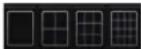
Selecting a Split Mode
Click a desired split mode from 1, 4, 9 and 16 split screen. Or press the [DISPLAY] button on the remote control until a desired split mode is displayed.
Auto Sequence
Click the Sequence button in the status bar, or press the [SEQ] button on the remote control. You can configure the sequence settings in
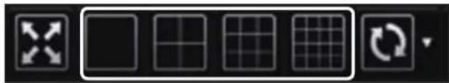
natural_image
Pure graphical toolbar icons without any text or symbolsControlling a PTZ
To control a PTZ camera, select the channel, then click PTZ button on the status bar, or press the [PTZ] button of the remote control to.

In PTZ mode, use the directional buttons to control the PTZ. Use [ZOOM], [FOCUS], [IRIS], [PRESET], and [SCAN/TOUR] to make adjustments to PTZ.
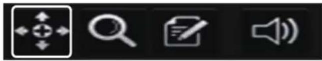
natural_image
Four black-and-white interface icons: zoom, document, speaker, and folder (no text or symbols)
Monitoring
Digital Zooming
You can enlarge the monitoring screen for better view.
Zooming will enlarge the video of the selected channel. If no channel is selected, channel 1 will be zoomed.
- Click Zoom in the status bar or move the cursor to a desired channel and right-click it to display the context menu. Select
. You can also press the [ZOOM] button on the remote control. - When the menu bar appears in the right bottom, use the buttons to control the zooming.
CH1 - CAM1 : Select a channel to zoom in/out.
: Zoom out the current (enlarged) image step by step.
: Enlarge the current image step by step.
Zoom Box : Use the yellow box to move to or select a desired zooming area.
EXIT : Exit the zooming screen and return to the live screen.
Digital zooming magnifies the video image digitally and produces enlarged images that may not be sharp and clear. For sharper and clearer magnification, it is recommended to use cameras supporting optical zooming.
Event Log
You can check the log of the events that occurred.
- Click Log to display the "EVENT LOG" window. The log list is sorted with the most recent event on top.
- Double-click a desired event to display the video.

Select an Audio Input Channel
Select a channel from which the audio signal will be received.
CHANNEL : Produces the selected channel's audio, regardless of the split screen mode.
LINK TO FULL SCREEN : When switching the DVR display mode to view one channel (Single Split), it produces the selected channel's audio.

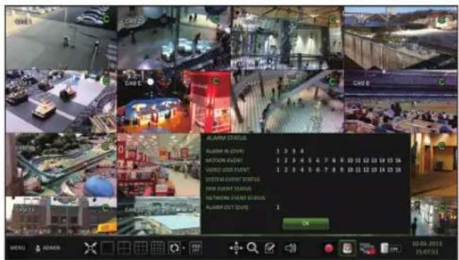
Check the Alarm Status
You can check alarms and events from each camera and the system. Click
Check the Network Status
Shows the connection status of cameras and network devices. Click
For more information, refer to "Network Status". (page 75).

flowchart
graph TD
    A["ACOMT"] --> B["CATAMAR"]
    B --> C["Network Status"]
    C --> D["Access Data"]
    C --> E["Connected Nodes"]
    D --> F["01:48:3.19(6MFS)"]
    D --> G["01:15:40:42.xx"]
    E --> H["01:15@40:42.com"]
    E --> I["01:15@40:42.com"]
    E --> J["01:15@40:42.com"]
    E --> K["01:15@40:42.com"]
    E --> L["01:15@40:42.com"]
    E --> M["01:15@40:42.com"]
    E --> N["01:15@40:42.com"]
    E --> O["01:15@40:42.com"]
    E --> P["01:15@40:42.com"]
    E --> Q["01:15@40:42.com"]
    E --> R["01:15@40:42.com"]
    E --> S["01:15@40:42.com"]
    E --> T["01:15@40:42.com"]
    E --> U["01:15@40:42.com"]
    E --> V["01:15@40:42.com"]
    E --> W["01:15@40:42.com"]
    E --> X["01:15@40:42.com"]
    E --> Y["01:15@40:42.com"]
    E --> Z["01:15@40:42.com"]
    E --> AA["01:15@40:42.com"]
    E --> AB["01:15@40:42.com"]
    E --> AC["01:15@40:42.com"]
    E --> AD["01:15@40:42.com"]
    E --> AE["01:15@40:42.com"]
    E --> AF["01:15@40:42.com"]
    E --> AG["01:15@40:42.com"]
    E --> AH["01:15@40:42.com"]
    E --> AI["01:15@40:42.com"]
    E --> AJ["01:15@40:42.com"]
    E --> AK["01:15@40:42.com"]
    E --> AL["01:15@40:42.com"]
    E --> AM["01:15@40:42.com"]
    E --> AN["01:15@40:42.com"]
    E --> AO["01:15@40:42.com"]
    E --> AP["01:15@40:42.com"]
    E --> AQ["01:15@40:42.com"]
    E --> AR["01:15@40:42.com"]
    E --> AS["01:15@40:42.com"]
    E --> AT["01:15@40:42.com"]
    E --> AU["01:15@40:42.com"]
    E --> AV["01:15@40:42.com"]
    E --> AW["01:15@40:42.com"]
    E --> AX["01:15@40:42.com"]
    E --> AY["01:15@40:42.com"]
    E --> AZ["01:15@40:42.com"]
    E --> BA["01:15@40:42.com"]
    E --> BB["01:15@40:42.com"]
    E --> BC["01:15@40:42.com"]
    E --> BD["01:15@40:42.com"]
    E --> BE["01:15@40:42.com"]
    E --> BF["01:15@40:42.com"]
    E --> BG["01:15@40:42.com"]
    E --> BH["01:15@40:42.com"]
    E --> BI["01:15@40:42.com"]
    E --> BJ["01:15@40:42.com"]
    E --> BK["01:15@40:42.com"]
    E --> BL["01:15@40:42.com"]
    E --> BM["01:15@40:42.com"]
    E --> BN["01:15@40:42.com"]
    E --> BO["01:15@40:42.com"]
    E --> BP["01:15@40:42.com"]
    E --> BQ["01:15@40:42.com"]
    E --> BR["01:15@40:42.com"]
    E --> BS["01:15@40:42.com"]
    E --> BT["01:15@40:42.com"]
    E --> BU["01:15@40:42.com"]
    E --> BV["01:15@40:42.com"]
    E --> BW["01:15@40:42.com"]
    E --> BX["01:15@40:42.com"]
    E --> BY["01:15@40:42.com"]
Monitoring
Check the Disk Status
You can check status and information on storage devices currently connected to the system.
Click
For more information, refer to "Disk Information". (page 103).

Saving Captured Snapshots
You can capture the current video screen and save or export it to a connected storage device.
- Select a channel fi rst, and right click on mouse to open popup menu, and select
menu item, or press the [SNAPSHOT] button of the remote control.
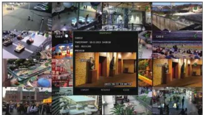
- Connect a storage device, and click the
button. To save the captured image to the built-in HDD, press the button.
Saved image can be found in the "Archive > Reserved data management" and can be backed up later. (Page 101)

- Enter the
and and press or button.
A progress bar appears and indicates the progress of exporting to storage device.
BURN: Snapshot is stored in the connected USB storage device.
ERASE & BURN : Deletes all fi les in the connected USB storage and then saves the snapshot.
Note thatoption erases all data on the USB storage device.
System Setting
To move to the System Setup menu
How to use the mouse


How to use the remote control 1
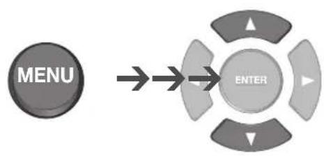
flowchart
graph LR
    A["MENU"] --> B["ENTER"]
    style A fill:#333,stroke:#fff,color:#fff
    style B fill:#999,stroke:#000,color:#fff
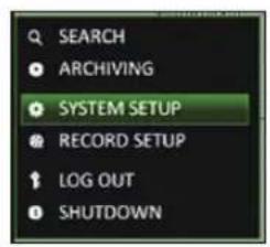

How to use the remote control 2
System Setting
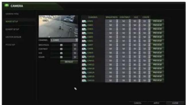
Camera Setting
You can configure the display settings of: camera title, hidden option, motion and camera type.
CAMERA TITLE
You can change the camera ID that is displayed on the screen.
- From
- Use the [▲▼◄►/ENTER] buttons on the remote control or use the mouse to select a channel that you want to rename. Alternatively, simply double-click the camera to rename from the top left corner.

- Once the virtual keyboard appeared, select desired alphanumeric characters to complete your input, and press the
button.
The
-
To apply the change, click
at the bottom of the screen. -
When done, press the [EXIT] button on the remote control or click
in the lower screen. A confirmation message appears and you will return to the previous menu.

For the SRE and SRP models, camera titles can be up to 16 characters, combining numbers and upper/lower case letters. (no spaces). For the SRL model, camera titles can be up to 8 characters.
Image Setup
You can adjust the brightness, contrast, color, and quality setting of each channel's camera.
-
From
-
Use [▲▼◄►/ENTER] buttons of the remote control or mouse to edit settings.
-
To apply your changes, click
button. -
Once completed, press the [EXIT] button of the remote control or click the
button on the bottom of the screen. A confirmation dialog appears and returns to the previous menu.
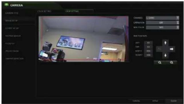
Crop Setting
On the SRE/SRPmodels you can crop camera images.
- From
-
Select the channel you wish to crop, then in the BOX POSITION section use the “-” and “+” and directional arrows to move the crop box. When finished, turn OPERATION to ON.
-
To apply your changes, click
button. -
Once completed, press the [EXIT] button of the remote control or click the
button on the bottom of the screen. A confirmation dialog appears and returns to the previous menu.
Covert Setup
You can make selected cameras "covert" so that specific users or user groups can not view the camera images.
-
Use the [▲▼◄►/ENTER] buttons on the remote control or use the mouse to select a covert channel(s) for a specifi c user group.
ADMIN, MANAGER, USER : Set them to. The selected channel(s) will be covert from the applicable user account. LOG OUT : Set it to
. When the user logs out, the current channel will be set to a covert channel. -
From
-
To apply the change, click
in the bottom of the screen. -
When done, press the [EXIT] button on the remote control or click
in the lower screen. The confirmation message appears and you will return to the previous menu. -
To set specific channels to COVERT for specific users, go to [USER], [MANAGEMENT], and select a USER ID. On the EDIT screen, you can assign what cameas are COVERT.
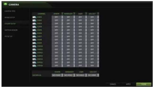
User can assign camera channel to display "Covert" or "No Video" while in covert mode
System Setting
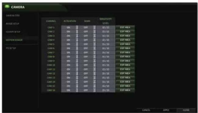
Motion Sensor
Set the motion sensor of the camera.
- From
- Use the [▲▼◄►/ENTER] buttons on the remote control or use the mouse to specify the use of each option item.
ACTIVATION : turn on or off the motion sensor.
MARK: Set toto display the motion detection indicator on each video tile.
SENSITIVITY: Set the sensitivity level of the motion sensor to either Daytime or Nighttime.
EDIT AREA : Specify the motion detection area.
- To apply the change, click
in the bottom of the screen. - When done, press the [EXIT] button on the remote control or click
in the lower screen. The confirmation message appears and you will return to the previous menu.
- The motion detection sensitivity may differ depending on the characteristics of the connected camera or the installation environment.
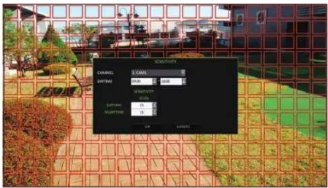
Motion Area Setup
From the motion sensor window, click
- Click
to move to the motion area setup screen. - If using the remote control, press the [ENTER] button to initiate the process.
- Use the arrow buttons to move to a desired block and press [ENTER]. The area setup will begin. Then, use the arrow buttons to specify the area. Press [ENTER] to select/deselect the area.
Alternatively, when using a mouse you can use the drag-and-drop method to specify or release the area.
- If you select the specified area again, it will be released.

Red Block = Selected area. The screenshot above shows the entire screen selected. These blocks are what triggers the motion sensor.
- Press the [EXIT] button on the remote control or right-click any area to display the popup window as in the right picture.
- While the popup window is displayed, select
to set the motion detection sensitivity of the channel currently selected.
Channel: Select the channel to set the motion sensitivity.
- SENSITIVITY : 1(Low) \~ 30(High) - The higher the number is, the higher the sensitivity level becomes.
DAYTIME : specify the time period that will be considered as daytime.
- DAYTIME : specify the
for the daytime. - NIGHTTIME : specify the
for the nighttime.
Images recorded in a low contrast scene such as at night can cause severe noise, which can trigger motion events too often.
If unwanted events occur frequently at night, you may want to reduce the motion sensitivity for the nighttime setting.
PTZ Settings
Set the camera ID, protocol, baud rate, and PTZ control speed for each channel.
- From
- Use [▲▼◄►/ENTER] buttons of the remote control or mouse to set protocol and baud rate of each channel.
Refer to the camera's manual or consult your installation technician for further information about your PTZ camera.
- To apply your changes, click the
button. - Once the setup has been completed, press the [EXIT] button of the remote control or click
button on the bottom. Click to return to the previous menu.

User will need to connect the PTZ camera(s) to the DVR's RS-485 ports on the rear panel.
System Settings
TAMPER DETECTION - (SRE/SRP ONLY)
Redirection, Blockage, and Defocusing of the camera(s) have been combined into the Tamper Detection function that has a simple On/Off Activation button in the menu
- Select
from -
Set the activation of each channel,
-
ACTIVATION: Set the detection for each channel to be enabled/disabled
- MARK: Turns on or off the detection indicator to be displayed on the screen
- LEVEL: The detection sensor's sensitivity; This can be separately set for day / night modes
- To apply the change, click
in the bottom of the screen. - When done, press the [EXIT] button on the remote control or click
in the lower screen. The confirmation message appears and you will return to the previous menu.
For more features, please see
PRIVACY MASK - (SRE/SRP ONLY)
Allows users to block out specific areas of camera image
-
Select
from -
Set the activation of each channel in the ACTIVATION tab.
-
ACTIVATION : Set to on for each camera channel that will utilize the featureMARK: Turns on or off the detection indicator to be displayed on the screen
- MASK COLOR: Choose the Privacy Mask color
- To apply the change, click
in the bottom of the screen.
Set the AREA SETUP of your Privacy Mask(s).
- Select the desired camera channel
- Set the activation of each channel in the ACTIVATION tab.
- Use the mouse to click-and-drag to select the designated masking areas. User can select up to 4 different areas per camera channel.
- When done, press the [EXIT] button on the remote control or click
in the lower screen. - The confirmation message appears and you will return to the previous menu.

You can configure screen display setup for the On-screen Display, Sequence, and SPOT Out.
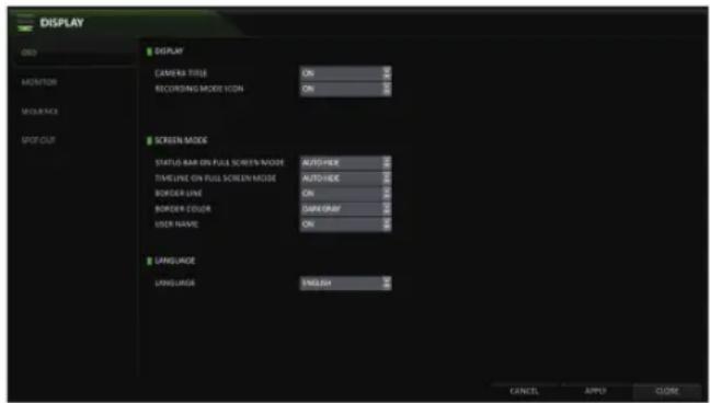
OSD
You can set the Camera Name, Icon, Status Bar, Timeline, Borderline, User Name and Language.
- From
- Use the [▲▼◄►/ENTER] buttons on the remote control or use the mouse to set each option of the OSD item.
CAMERA TITLE : specify the display of the camera title on the screen.
RECORDING MODE ICON : shows/hides the record mode icon on the screen.
STATUS BAR ON FULL SCREEN MODE : select to show or hide the status bar in full screen mode.
-AUTO HIDE: move the cursor to the lower area of the screen to display the status bar. When moving the cursor up, the status bar will disappear.
- ALWAYS ON : The status bar will be displayed at all times.
-5 SEC \~1 MIN : If no mouse movement is detected from 5 seconds to 1 minute, the status bar will disappear.
TIMELINE ON FULL SCREEN MODE : shows/hides the timeline in full screen mode.
- AUTO HIDE : move the cursor to the right margin to display the timeline. Move the cursor to the left to hide the timeline.
- ALWAYS ON : The timeline will be displayed at all times.
- ALWAYS OFF : The timeline will not be displayed.
BORDER LINE : displays the cross-border between channels in split mode
BORDER COLOR : select a color for the border.
USER NAME : displays the currently logged-in users on the status bar.
LANGUAGE : select a menu display language.
- To apply the change, click
in the bottom of the screen. - When done, press the [EXIT] button on the remote control or click
in the lower screen. The confirmation message appears and you will return to the previous menu.
System Setting
Monitor
Adjust the dwell times for Sequence and Spot.
- From
- Use the [▲▼◄►/ENTER] buttons of the remote control or mouse to set the dwell times for Sequence mode and SPOT Out.
SEQUENCE DWELL: Sets the time interval to the next screen (Can set to 1 sec \~ 60 sec). Default is 5
SPOT DWELL : Sets the time interval to the next view type. (Can set to 1 sec \~ 60 sec) Default is 5 - VIDEO ASPECT RATIO : User can specify the Aspect Ration; 16:9 or 4:3

-
DISPLAY RESOLUTION : User can select the display resolution from the list: Auto, 1280x1024, 1280x720, 1920x1080
-
To apply the change, click
in the bottom of the screen. -
When done, press the [EXIT] button on the remote control or click
in the lower screen. The confirmation message appears and you will return to the previous menu.
Sequence
Confi gure the sequence feature.
- From
- Use the [▲▼◄►/ENTER] buttons on the remote control or use the mouse to add a sequence or change the activation setting of the existing sequence.
ACTIVATION : Activates the selected sequence.
ADD : Add a sequence. -
To apply the change, click
in the bottom of the screen. -
When done, press the [EXIT] button on the remote control or click
in the lower screen. The confirmation message appears and you will return to the previous menu.
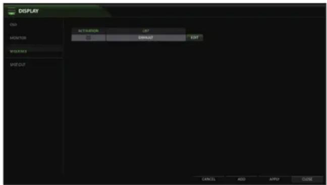
To add a sequence
- Click
in the bottom of the screen. - When the "ADD" dialog appears, enter a title using the virtual keyboard. (8 Characters)
- Enter the name of the sequence, set ACTIVATION to ON, then click
. - Select Activation ON/OFF
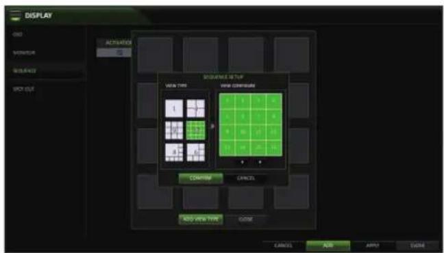
- Select
. -
When the "SEQUENCE SETUP" dialog appears, select a split mode that you want to add from
. -
When the selected split mode is displayed on
, select a channel you want to display in each split screen. -
Click
. The set sequence mode is confirmed and will be added to the Sequence list. -
When done, click
in the bottom of the screen. After the sequence type is saved, you will return to the previous screen.

System Setting
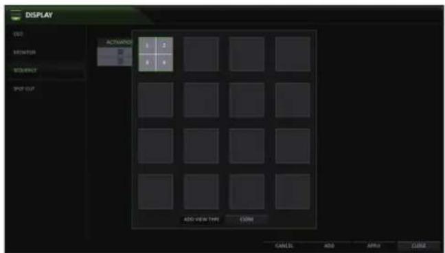
To edit a sequence
- Select a sequence that you want to edit in the list by clicking the
button, or double-clicking the sequence title - The "EDIT" dialog appears.
- Use the [▲▼◄►/ENTER] buttons on the remote control or use the mouse to edit the selected sequence.
SEQUENCE TITLE : enter a new sequence name.
ACTIVATION : Activates/Deactivates the sequence.
MODIFY : change the sequence settings.
DELETE : delete the selected sequence.
CANCEL : cancel the changes.
- Pressing the
button will display the Modify Sequence window. - To change the existing settings, select a screen mode that you want to edit and right-click to display the context menu. Then, select
. - When done, click
to close the window. - To apply your changes, click
.

SPOT OUT
You can configure the Spot Out to display a Live channel in various live view types (depending on model).
From


- FEATURES
- Table of Contents
- INTRODUCTION
- VT-SHE-A
- VT-SHP916A
- MONITORING
- SYSTEM SETTING
- RECORD SETTING
- SEARCH
- PLAY
- ARCHIVING
- WEB VIEWER
- MOBILE VIEWER
- ARCHIVE VIEWER
- APPENDIX
- Safety Instructions
- Before installation
- In operation mode
- Disassembly & Cleaning
- During installation
- While in use
- What's included
- SpireHD Series Remote
- SR-SERIES Remote Control At a Glance
- Change the remote control ID
- VT-SHE-A Overview
- VT-SHE-A Series
- VT-SHE-A Key Features
- VT-SHE-A Rear Panels
- VT-SHE-A Installation
- Replacing HDD
- 4-Channel Model
- 8-Channel Model
- Basic Layout
- Connecting to an external device
- Connecting to a Monitor
- Power Connection
- Alarm I/O Connection (VT-SHE908A)
- To connect the alarm input signal
- To connect the alarm output signal
- Communication Port (VT-SHE908A)
- RS-485 Connection
- Audio Device Connection
- Storage and Mouse Connection
- USB Device
- Network Connection
- PC Connection - Remote Network
- VT-SHP916A Overview
- VT-SHP916A Key Features
- VT-SHP916A Installation
- Replacing All 5 Hard Drives
- Connecting to the monitor
- Alarm I/O Connection
- Communication Port
- RS-232 Connection
- PC connection in the local network
- PC connection from a remote network
- Notes
- START
- Log In
- Log Out
- System Shutdown
- Live Screen At a Glance
- Video Window
- Status Bar
- Timeline
- Quick Menu
- Using the status bar in the live mode
- Selecting a Split Mode
- Auto Sequence
- Controlling a PTZ
- Digital Zooming
- Event Log
- Select an Audio Input Channel
- Check the Alarm Status
- Check the Network Status
- Check the Disk Status
- Saving Captured Snapshots
- To move to the System Setup menu
- Camera Setting
- CAMERA TITLE
- Image Setup
- Crop Setting
- Covert Setup
- Motion Sensor
- Motion Area Setup
- PTZ Settings
- System Settings
- TAMPER DETECTION - (SRE/SRP ONLY)
- PRIVACY MASK - (SRE/SRP ONLY)
- OSD
- Monitor
- Sequence
- To add a sequence
- To edit a sequence
- SPOT OUT
- Spot Out View Types
- To add a View Type to a Spot Out
- To edit or delete View Type of the SPOT Output
- LOOP OUT (SRE Only)
- Audio
- Buzzer
- User Settings
- Management
- To add a user account
- To edit the user account information
- Group Authority
- Network Setup
- IP Setup
- DDNS
- Network Status
- Date/Time
- System Management
- To perform an upgrade
- System Information
- Control Device
- Storage
- Disk Information
- RAID Hard Drive By
- Connecting an External Disk/RAID Bay/Hard Drive Bay to the DVR
- Disk Operations
- S.M.A.R.T settings
- Event Setup
- Alarm Out
- ON/OFF Schedule
- Event Notification
- Buzzer output
- Display
- Alarm Sensor
- Video Loss
- System Event
- Disk
- Record
- System
- Network
- Tampering Event (SRE/SRP only)
- To start the Record Setup menu
- Record Setup
- Operation Mode
- Auto Confi guration
- Manual Conf i guration
- Continuous Recording
- Size/FPS/Quality Setting
- Schedule Setting
- Motion Recording
- Alarm Recording
- Panic Recording
- To move to the Search menu while in monitoring
- To move to the Search menu while in playback mode
- Search Settings
- Time Search
- Thumbnail Search
- Event Search
- If you want to play
- Playback screen configuration
- Menu / split-screen selection menu
- Play Bar
- Bookmarking
- To start the Archive menu
- Archive
- Reserved data management
- Playing the archived data
- Archive Devices Setup
- What is the Web Viewer?
- System Requirements
- Connection
- To connect to the DVR from inside
- To connect to the DVR from outside
- Live
- No. Item Description
- Switching the split mode
- To save the video
- Screen capture
- ActiveX Settings
- Status tab
- Log tab
- PTZ tab
- Search Viewer at a Glance
- Search by time
- Search by event
- Setup
- Setup Viewer at a Glance
- Camera
- Name the camera title
- Covert Setting
- Motion Setting
- PTZ Setup
- OSD Setting
- Monitor Settings
- Audio/Buzzer
- User
- User Management
- Group Permission Setting
- Network Setting
- DDNS Setting
- Email Setting
- Date/Time Setting
- Control Device Setting
- Device Information
- S.M.A.R.T Status
- Sensor
- Alarm Output
- About
- Web Viewer Information
- SPIRE DVR SMARTPHONE APP
- SPIRE Viewer specification
- Using the SPIRE Viewer on the iPhone
- To connect to the DVR with SPIRE Viewer
- Split Mode
- Using the Log View
- Using the Search function
- Using the Setup function
- Using nViewer with Android
- To connect to DVR with nViewer
- Getting started with the Backup Player
- Backup Player At a Glance
- Image Capture
- Print Out
- Settings
- CONSIDER THESE OTHER GREAT PRODUCTS!
- PREMIUM
- TVI CAMERAS
- IN-STOCK & READY
- FOR SHIPMENT!
- The Mighty Dome Trio Offers HD-SDI, EX-SDI, TVI & CVBS All-in-One Solution and Feature:
- MegaPixel Premium Smart HD-TVI & EX-SDI True Day/Night WDR Bullet Cameras Feature:
- VITEK LIMITED PRODUCT WARRANTY
Brand : Vitek
Model : VT-SHE904A
Category : Radio