JKU-Pods - Speaker Select Increments - Free user manual and instructions
Find the device manual for free JKU-Pods Select Increments in PDF.

User questions about JKU-Pods Select Increments
0 question about this device. Answer the ones you know or ask your own.
Ask a new question about this device
Download the instructions for your Speaker in PDF format for free! Find your manual JKU-Pods - Select Increments and take your electronic device back in hand. On this page are published all the documents necessary for the use of your device. JKU-Pods by Select Increments.
USER MANUAL JKU-Pods Select Increments
JKU-PODS INSTALLATION INSTRUCTIONS
** (4) screws go into the metal sport cage to affix the pods. Follow instructions for a good installation **

These instructions and all pictures show installation of the Driver Side JKU-Pod with the Kicker® component speakers. Installing the Passenger Side JKU-Pod is the same procedure in mirror image. Instructions should be used as a general guide to installing other component systems or coaxial speakers.

Tools required:
Drill
3/8" Hex-Head Driver Bit Phillips Bit
Exacta Knife or Razor Blade Small piece 12 " thick wood Zip Ties / Cable Ties
(Other tools possibly required):
-Rotary Tool w/ Sanding Drum
-Wire cutters / crimp tool
-Other wiring accessories such as solder, glue gun, heat shrink tubing, electrical tape, etc.
*A second set of hands is helpful when attaching pods, but not absolutely necessary.

natural_image
Close-up of a car's front window showing the hood and seat area with visible stitching lines (no text or symbols)No need to unzip or remove any of this, but here's some photos of the driver side area where the driver side pod will go. (If the images aren't very clear, you can always print color copies from our site.) This picture is taken from standing at the rear of the Jeep, fabric unzipped, exposing the 'pop-in' foam piece and the metal sport cage. The foam pieces should not be removed. We're just showing you how and where the pods will affix...you don't need to unzip any of this to affix the pods. The pods install right on top of all of this stuff. The foam is very rigid and doesn't compress under screw pressure.

natural_image
Close-up of a person applying adhesive to a large cylindrical object on a vehicle (no visible text or symbols)These two photos show you where the screws will penetrate the foam and affix the driver side pod. (Think mirror image for the passenger side.) The foam can sort of jiggle around, but that goes away when the pods are installed.

natural_image
Close-up of a hand adjusting a metal object on a vehicle (no visible text or symbols)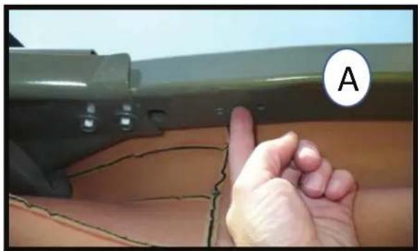
natural_image
Close-up of a hand pointing at a damaged green object with visible cracks and a circular label labeled 'A' (no text or symbols on the object itself)In these photos with the foam piece removed, you can see where the screws will enter the sport cage on the driver side. (Mirror image for passenger side.)
natural_image
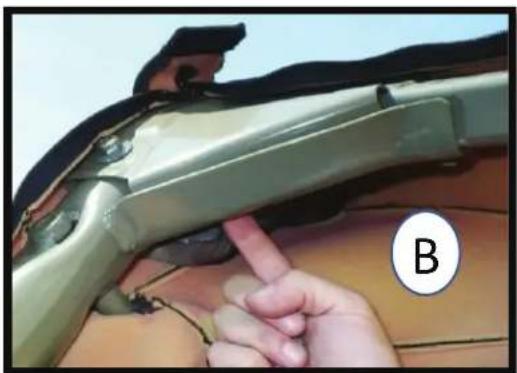
Close-up of a hand inserting a finger into a car's hood, with part labeled B (no text or symbols on the object itself)Note also in these photos how the angle of the metal is different for each screw used to affix the pod; the screw in photo (A) will enter at a higher trajectory, more straight up toward the sky. The screw in photo (B) will enter at a lower trajectory. Why are we showing you all of this? We want you to see this area with everything removed to help understand where the screws are going because all of this is intact when you install the pods and we figured you may want to see exactly what/where you're drilling into.
(If you're using your own speakers and purchased the pods empty)
natural_image
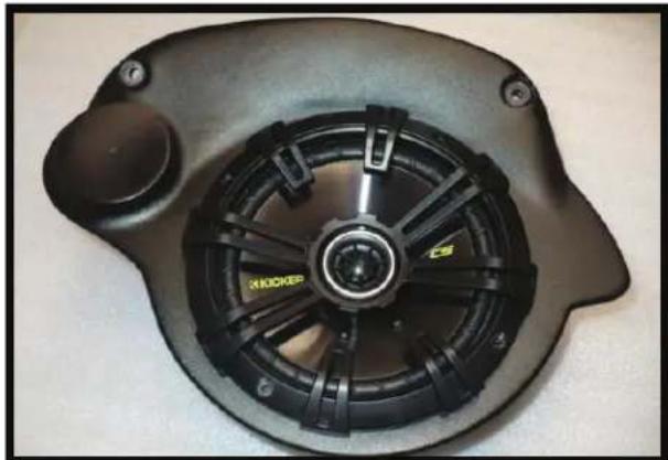
Close-up of a black mechanical fan or motor component with visible blades and mounting holes (no text or symbols)For those installing their own coaxial speakers with no separate tweeters, you'll simply leave the tweeter sections uncut and install your coaxial speakers similar to the Kicker Coaxial shown in the photo here.

text_image
This step is for those installing their own component speakers.If installing your own component speaker system, you'll need to follow your manufacturer's instructions and cut out the proper size tweeter holes. Sizes vary and need to be precise which is why we leave them uncut (unless you purchased the pods with the Kicker® component system).
Some possible crossover locations if you're using component speakers:
(Please decide where you'll put the crossovers before installing speakers or affixing the pods.)

natural_image
Interior view of a black electronic device with wires and a labeled component (A), no readable text or symbols beyond the label.A: Crossovers can be placed inside the pods. We dropped one in the driver's side pod to show the best mounting orientation (driver's side pod shown).
Positives: Total protection from the elements and offers some possible additional theft protection.
Negatives: Can't easily change switches on crossovers and should probably remove excess wire or at least make sure it's wound up and can't rattle.
natural_image
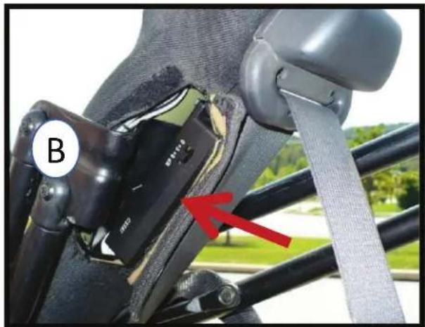
Close-up of a car seatbelt buckle with a red arrow pointing to the lower side (no text or symbols visible)B: Using a couple of zip ties could provide a place for the crossovers behind the hook & loop opening in the fabric for the soft-top bars.
Positives: Easy access to the switches on crossovers and can hide excess wire under padding.
Negatives: Less protection from the elements...maybe consider putting them in plastic bags for additional protection from moisture?
HINT: If you opt to put the crossovers inside the pods, you should consider powering up the tweeters temporarily to decide crossover level switch settings before they're inside the pods and behind the woofers. (Kicker crossover points only increase volume to the tweeters, not the woofers).
Speaker Installation: Tweeters are first, pick a method...

natural_image
Three black plastic washers on a surface, one labeled 'FLUSH MOUNT' (no other text or symbols visible)
A flush mount would have the trim ring up against the tweeter and the 'nut end' of the shorter mounting nut placed against pod from inside.
Tighten tweeter into place by turning the nut from inside.

text_image
FLUSH MOUNT
You need to pick a mounting configuration (flush mount or angled). Shown here are the Kicker tweeter, trim ring, and shorter mounting nut needed for a flush mount scenario.
OR...
An angled mount of the Kicker tweeter requires you to slightly widen the hole (using a rotary tool with a sanding drum works) so that the threaded section of the longer mounting nut can pass through the hole as shown. Consult Kicker instructions for sequence of tweeter pieces. It can take a little time to get things angled the way you want and secured.

text_image
ANGLED MOUNT

text_image
NO MATTER WHICH WAY...Flush or angled, you'll want the tweeter logo positioned at about the angle seen here (driver side pod) for final install. (Mirror image position for passenger pod.)
Next - If installing crossovers outside of the pods...

natural_image
Close-up of a black electronic device with a circular vent and wires, labeled with number 1 (no text or symbols on the device itself)With tweeter installed, pull its' wires through the grommet hole (no grommet installed in hole yet).

natural_image
Close-up of a finger holding a black cable with a connector, placed on a textured surface (no text or symbols visible)Push grommet over the tweeter's wires.
natural_image
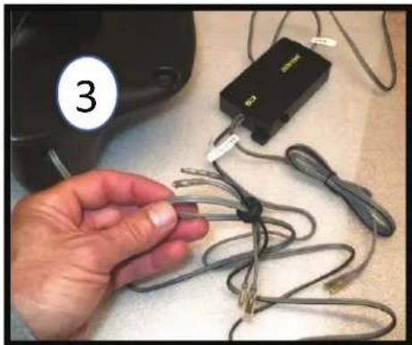
Hand holding a cable with attached electronic device labeled '3' (no text or symbols on cable)Then push the labeled 'Mid' wires through the grommet in the opposite direction. It's a tight fit but that minimizes air escaping the pod.
natural_image
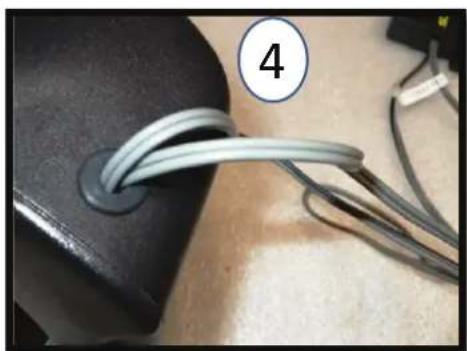
Close-up of a black object with two coiled wires attached, labeled with number 4 (no text or symbols on the wires themselves)Insert grommet w/ wires into hole in pod. Push through from outside while pulling grommet from inside and you'll be able to get it through and inserted properly as shown. Keep only enough wire inside the pod to connect to the woofer and tweeter. Here's where you may want to use a glue gun or wax, etc. to fill any gaps around the wires so air can't escape the pod. Not absolutely necessary, but if you get a whistling sound, this is likely why.
If installing crossovers inside pods:

natural_image
Close-up of hands adjusting a black object with a small inset detail, labeled with number 1 (no text or symbols on the object itself)Insert your rubber grommet. This is where the wires will exit the pod.

natural_image
Hand inserting cables into a black device casing (no visible text or symbols)While it's better to remove the excess, if you'd rather not cut and solder the wires shorter, you can use a long zip tie as shown and wrap all the excess wire length, holding in place on top of the crossover. Just be sure it's tight and secure so there's no rattling later. Leave a little 'Mid' wire out so you can attach to the woofer. Pull the input line through the grommet hole and out of the pod. Later, you'll connect it to the length of speaker wire that comes from your amplifier (see wiring instructions pages).
natural_image
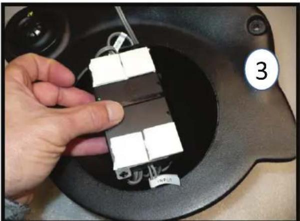
Hand holding a small electronic device with three white components inside a black circular device (no visible text or symbols)And if you purchased the pods with the Kicker component system included, they come with correctly sized tape squares for the crossovers...
natural_image
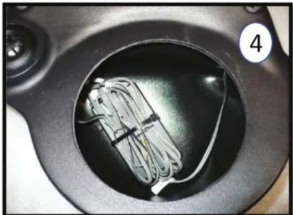
Close-up of a black circular container with a coiled cable inside, no visible text or symbols...so you can affix the crossovers inside the pod as shown, leaving enough 'Mid' wire out to connect to the woofer.
Woofer installation:

natural_image
Close-up of a hand holding a small electronic device with wires, next to a white spherical object (no visible text or symbols)Re-install the poly-fill and connect the 'Mid' wires to the woofer.

natural_image
Close-up of a black ergonomic device with a hand adjusting its interior panel, no visible text or symbolsAffix the woofer with the logo oriented in same manner as the tweeter logo for the best appearance.
Attaching pods to the sport cage:
natural_image
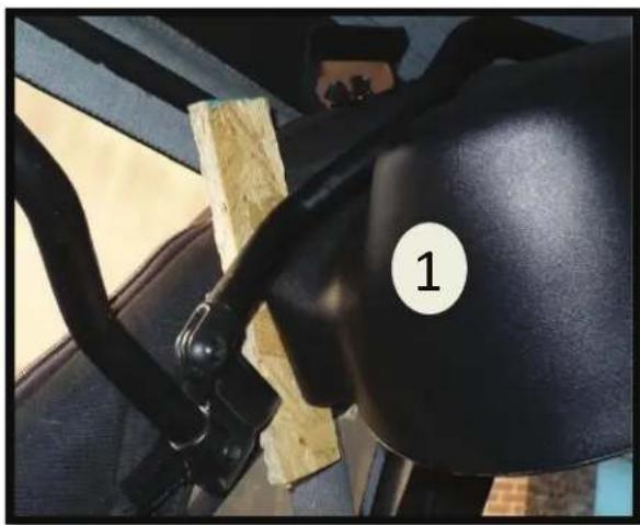
Close-up of a car's seatbelt and steering wheel, showing black grip and wooden frame (no text or symbols visible)Getting a feel for where it will go - use a small piece of wood that's 12 " thick to show how close the JKU-Pod should be to the downward sport bar. Place the wood as shown in the photo so it spans that side of the pod appropriately. Wood piece should butt up against fabric & metal; any factory wiring under the fabric should be moved aside.

text_image
You're in the right spot when the seat belt mount swivels, just clearing the pod.With the 12 ” wood spacer in place, you can tell the pod is at the correct angle when the seat belt guide (shown) can swivel past the pod, missing it by just a little bit. (If it’s missing it by more than 14 ” you need to swing the pod forward). This ensures the first screw goes in at the right spot!
3
It's helpful to slide the pod around a bit, feeling where it fits best, like a sweet spot.

text_image
4Prior to screwing the pod in place, you must decide how to get the speaker wires under the fabric. 1) You can run them through the factory opening for the soft top bars with a small amount of wire showing, or 2) you can use a razor blade and cut a tiny slit in the fabric right next to the grommet hole so the speaker wires exit the pod immediately going under the fabric. If choosing that way, hold the pod in place, determine where the slit should be made, remove the pod and make the slit.
text_image
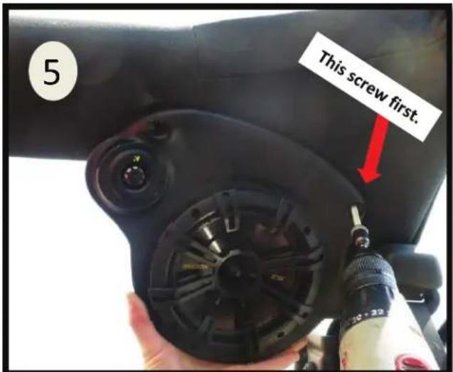
5 This screw first.Installation is easier if you first feed the speaker wire behind the fabric, especially if you made the fabric slit.
The screw nearer the seat belt is first. Wood spacer in place and pod butted to it, seatbelt mount should still swivel and just misses pod as shown in #2. While maintaining this angle, hold underbelly of pod and push it into its little nook in the cage's "corner" to remove any play in the foam piece underneath. Hold pod firmly in place and drill steady. Pre-drilled screw hole in pod acts as guide & starts the screw at the correct angle. Screw punctures the fabric, quickly spins through the foam and hits metal. It will cinch down nicely within a few revolutions of breaking through the metal.
Generally under tweeter area, push pod up to remove any play in the foam underneath. The screw is roughly perpendicular to the fabric and pre-drilled hole acts as guide for proper direction. Hold the pod firmly in place: the screw will puncture the fabric, quickly spin through the foam and hit metal. Hold everything steady throughout this process allowing the screw to drill through metal. Once you're through, the pod will cinch down nicely against the fabric within a few revolutions.

text_image
This screw next. 5
natural_image
Close-up of a hand using a small tool to apply material, no visible text or symbolsThe screw recess areas are a tight fit not just for a nice look, but for rigidity since they're the mounting points and flex in the plastic should be minimized. So, if a screw went in a little off-center and you're having trouble popping the screw cap over the head, no worries. The caps are thick plastic and you can easily remove some with a rotary tool or even shave some excess off carefully with a razor blade until the cap can clear the pods' recess and pop on the screw head.

natural_image
Close-up of hands holding a red tool against a wooden surface (no text or symbols visible)
Repeat process for passenger side pod. Hint: when affixing the pod, make sure it's at the same pitch as the driver side pod for best appearance.


text_image
STEALTH-POD Select Increments 4WD Audio www.jeepsound.comWe also make the Stealth-Pod for Wrangler JKU's like yours: It holds a 10" subwoofer and suspends on the tailgate. It's also portable.
HOW TO WIRE IN YOUR NEW JKU-PODS
These instructions are of installing the #30647KL version of the JKU-Pods (Kicker amplifier included) in a factory sound system with the basic 130 Radio. Some connectors and hardware shown are included only with this version.
These instructions describe wiring paths with the amplifier located under the Driver Seat.
*If you purchased #30647KL with Kicker amplifier included and are installing the pods in a factory stereo system, use the 20' length of speaker wire included in the amp wire kit to tap into the factory speaker wires described in #4, and use the other 25' speaker wire length included in your #30647KL kit for #1-3.

natural_image
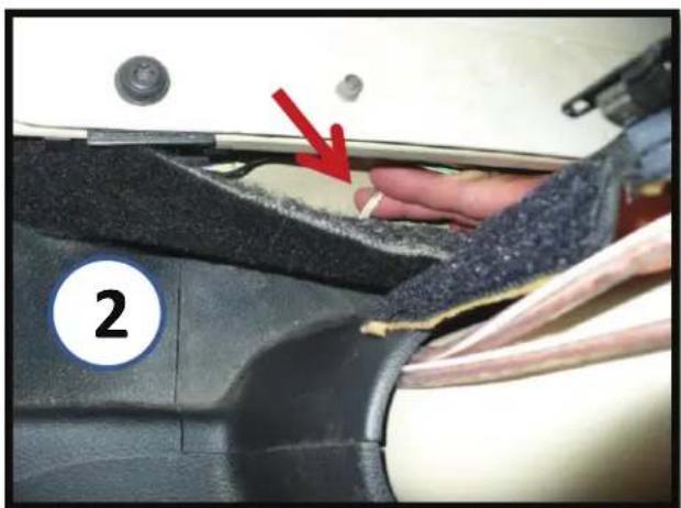
Close-up of a car interior showing white and orange insulation material, with a numbered label '1' in the corner (no readable text or symbols on the main subject)You must run two sets of speaker wires from the pods to your amplifier. Make note of which are left, right and pos.+ and neg. – so you know which is which up at the amp. Start with the passenger side pod: unzip the sport bar fabric to slip the wire underneath.
When it's over by the driver side pod, start a second run of wire for the driver side pod and bring both pairs together down the sport bar as shown here.
natural_image
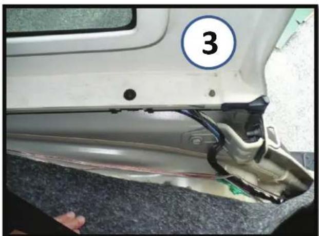
Close-up of a car's side panel showing a numbered circle and a damaged component, no visible text or symbols.Continue running the speaker wires under the carpet along the driver side wheel well. Bring them under the rear floor carpet until you get under the driver seat. They can exit at seat bracket or you can make a slit in carpet at the exact spot where they'll connect to the amp.
Gray with Light Green Stripe is Left Rear (+)
Gray with Dark Green Stripe is Left Rear (-)
natural_image
Close-up of a hand pressing down on a car seatbelt with a red arrow pointing to a component (no text or symbols visible)Pulling the carpet back, you can grab the wires as they're fed under the plastic piece at the base of the sport bar.
natural_image
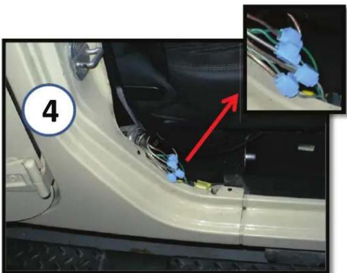
Close-up of a white car door panel with wiring and a red arrow pointing to a small component, inset shows close-up of blue wire wires (no text or symbols visible)If you don't have an aftermarket radio and are tapping into the factory sound bars' speaker wires for signal, do it here by the passenger seat. The wires are under the plastic trim. Pop out the two plastic rivets and remove some of the electrical tape. Your wires will go under the carpet. Follow the wire color code below, making sure to mark which is which for the amp.
If purchased version with Kicker amplifier included, you have these blue lock wire connectors (shown).
Dark Green with Light Green Stripe is Right Rear (+) Dark Green with Gray Stripe is Right Rear (-)
natural_image
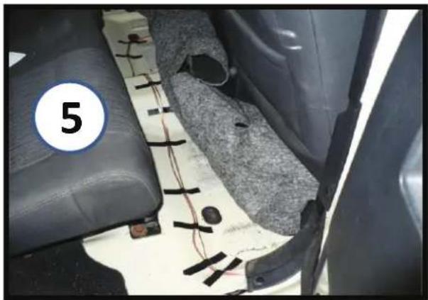
Interior view of a car showing leather seats, wiring, and a numbered component (no readable text or symbols)Now run the wires over to where the amplifier will be installed under the driver seat. If using your own amp, it will have either a High Level Input with a small plug of wires, or a High/Low Level button the wires will connect to using RCA adapters. Consult the manual for your amp.
*If you purchased the pods with the Kicker amplifier, specific RCA connectors are included. Make note of which wires are left, right, pos.+ and neg.- wiring them as indicated on the RCA housings, and you must have the button on the Kicker amplifier set for High Level input.
natural_image
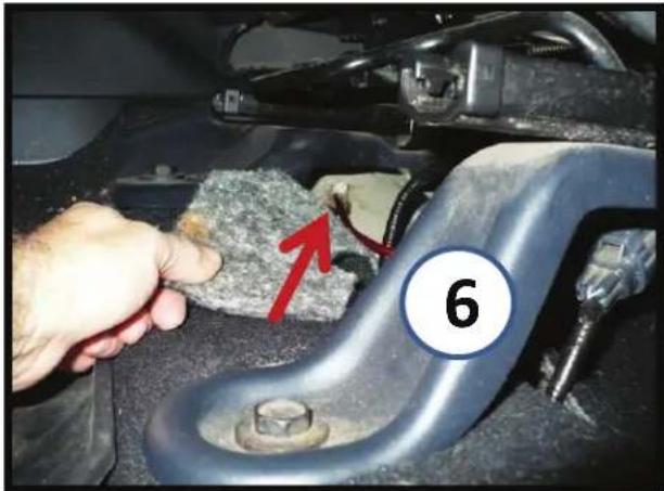
Close-up of a hand inspecting a car engine component with a red arrow pointing to a textured material, labeled '6' (no readable text or symbols beyond label)Amplifier Ground: An easy connection is already right under the Driver seat. It's up by the inner seat bracket on the uphill slope of the floor. Use 10mm wrench to loosen the nut and use a ring terminal on the ground wire. Ground Wire must be connected to amp prior to attaching Power or Remote Wires to amp!
natural_image
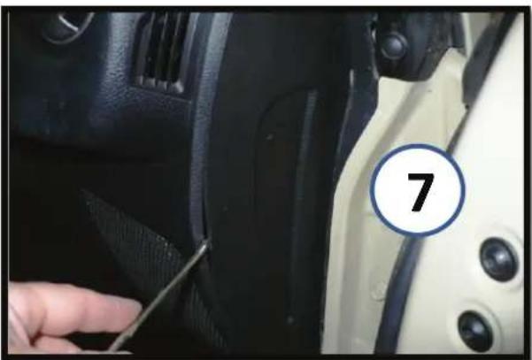
Close-up of a car interior showing a finger inserted into the seat area, with a numbered circle highlighting the number 7 (no text or symbols on the main subject)Amp Power Wire: Pop off this little side panel on the passenger side dash with a flathead screwdriver. It pops off easily. (This is the panel in later models).

natural_image
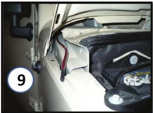
Close-up of a car interior showing a hand using a tool to adjust the engine compartment, with a numbered marker '8' on the door (no text or symbols on the main subject)Behind it is a little hole that has foam in it. Use a piece of wire such as a coat hanger with the power wire taped to it and poke it through.
natural_image
Close-up of a car engine bay with visible battery and wiring, no text or symbols presentPower wire will pop through here. Note: if you're adding other amplifier(s) for other audio upgrades you should run separate Power wires for them.
natural_image
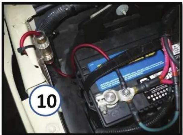
Close-up of a car battery pack with red cables and wiring, no visible text or symbolsFuse holder can be mounted by battery as shown. Don't connect the power wire unless amp ground wire is already connected so amp is grounded!
natural_image
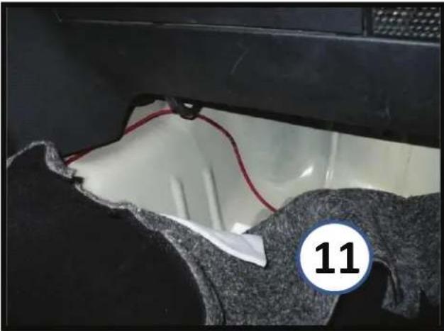
Close-up of a car interior with visible wiring and fabric, marked with number 11 (no text or symbols on main subject)Run Power Wire under carpet in passenger foot area and feed it under center of dash on top of metal hump until it exits over in the driver foot area. Leave it there for now and let's move on to the amp's Remote Wire.

natural_image
Interior view of a car dashboard with air filters and control panels (no readable text or symbols)'07-'10, pop out the cigarette lighter housing on the left using a small pick or tiny flathead- the tabs right behind the face can be pushed in to pop it out.
(Easier than removing the whole dash piece).
This is the switched port you want to use and the blue wire with pink stripe is the wire you want to splice into for the Remote amp wire. You can feed the wire down behind the panel and into the driver foot area, under the carpet. Note: if you're adding other amplifier(s) for other audio upgrades, you only need to run this single Remote wire over to the amp(s) and can then splice into it for additional short runs to the other amp(s). Next follow #14, then #16 for the rest of your '07-'10 install.
Next step is the amplifier Remote Wire. 2007-2010 models see #12. 2011-2016 models see #13.

text_image
Car dashboard control panel with red arrows and circled highlights, labeled with number 13For '11-'16, pop out window switch panel with a good tug and unplug it. Then remove the single screw (arrow). This allows you to pop off the top piece of the dash a little (the piece with the vents) so you can pop off the lower AC Control piece that has the cigarette lighter outlet. It is piggy-backed to the top vent piece with plastic mounts at the red circles and you need to slide it off them. Then you can reach behind and unplug everything to gain better access to the outlet wiring. Next follow # 14.

natural_image
Close-up of a yellow and blue plastic electrical connector with black wires against a dark background, labeled with number 14 in the corner (no text or symbols on components)Tap into the blue wire with pink stripe. The Black/White Stripe wire is the Ground and remains as-is. Note: if you're adding other amplifier(s) for other audio upgrades, you only need to run this single Remote wire over to the amp(s) and can then splice into it for additional short runs to the other amp(s).
natural_image
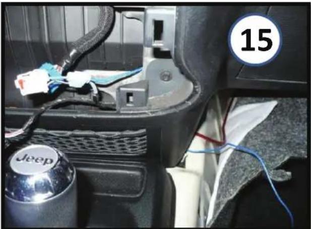
Interior view of a car showing a Jeep brand wheel, cable, and wiring (no readable text or symbols)'11-'16 Feed remote wire down behind dash to meet up with power wire and run remote wire under dash to driver side area just like power wire was done. Note: if you're adding other amplifier(s) for other audio upgrades, you only need to run this single Remote wire over to the amp(s) and can then splice into it for additional short runs to the other amp(s).
natural_image
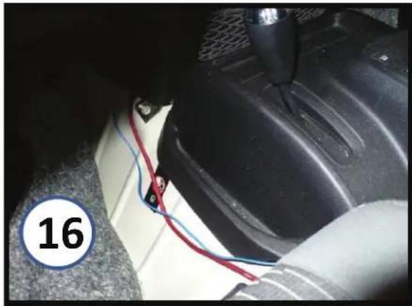
Close-up of a car interior showing a blue and red cable being inserted into a car wheel (no text or symbols visible)Bring the Remote and Amp Power wires under the carpet, between driver seat and center console so they can come up from under the carpet under the driver seat. You can bring them up where the other factory wiring for the seat exits, or cut slits in the carpet exactly where they will need to be for the amp.

natural_image
Interior view of a car showing a mounted electronic device with wiring and indicator lights (no visible text or symbols)A clean looking install of the Kicker amp under the driver seat with only the speaker input leads showing. Easy access to amp's controls from here, and all other wires are on other side of amp and hidden from view.
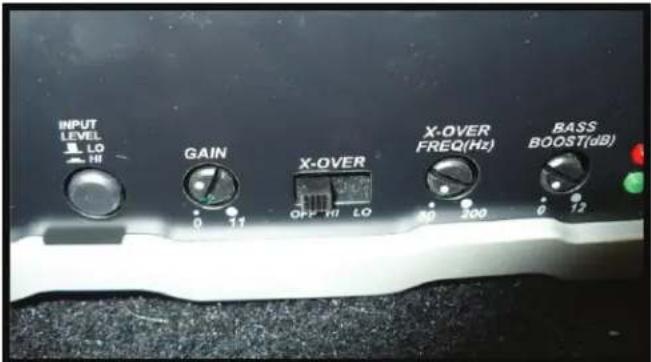
text_image
INPUT LEVEL LO HI GAIN X-OVER OFF HI LO X-OVER FREQ(Hz) 30 200 BASS BOOST(dB) 0 17 0 12For Kicker amp, this is how we ended up setting ours: Stock 130 radio in our Jeep so input level is on High and we tapped into the sound bar speakers. We put the gain about a third of the way up and kept the x-over off so the pods get the full audio spectrum. We had the bass boost down/off. We had our regular stock 130 radio set at +4 bass, +1 treble, +2 mid, balance centered and fader at +4 Front. It's at least a good starting point for you if you got the Kicker amp too.