
BP480V370NB - UPS Tripp Lite - Free user manual and instructions
Find the device manual for free BP480V370NB Tripp Lite in PDF.


| Product Type | Extended-Run Battery Cabinet |
| Model | BP480V370NB |
| Dimensions (H x W x D) | 2005 x 647 x 1100 mm |
| Empty Weight | 266 kg (empty cabinet) |
| Battery Configuration | 40 x 12V DC batteries (user-supplied) |
| Nominal Voltage | 480V DC (±240V DC) |
| Circuit Breaker Rating | 400A, 600V DC |
| Maximum Parallel Cabinets | 3 |
| Construction | Heavy gauge steel with powder coat finish |
| Ventilation | Front and rear vents for convection cooling |
| Door | Hinged lockable door |
| Overcurrent Protection | Molded case circuit breaker |
| Cable Entry | Conduit knockouts on top |
| Battery Type | Valve-Regulated Lead-Acid (VRLA), user-supplied |
| Included Components | Cable jumpers, terminals, circuit breaker |
| Operating Temperature | 0°C to 40°C |
| Storage Temperature | < 40°C, relative humidity < 90% |
| Warranty | 1 year limited |
| Maintenance | Quarterly voltage and connection check |
| Mounting | Floor-standing, level surface |
Frequently Asked Questions - BP480V370NB Tripp Lite
User questions about BP480V370NB Tripp Lite
0 question about this device. Answer the ones you know or ask your own.
Ask a new question about this device
Download the instructions for your UPS in PDF format for free! Find your manual BP480V370NB - Tripp Lite and take your electronic device back in hand. On this page are published all the documents necessary for the use of your device. BP480V370NB by Tripp Lite.
USER MANUAL BP480V370NB Tripp Lite
Extended-Run Battery Cabinet
Models: BP480V370, BP480V370NB
Not suitable for mobile applications.
natural_image
Exterior view of a double door with grid pattern and handle (no text or symbols)

1111 W. 35th Street, Chicago, IL 60609 USA • www.tripplite.com/support
Copyright © 2018 Tripp Lite. All rights reserved.
Table of Contents
1. Introduction 2
Features 2
2. Important Safety Instructions 3
Installation and Location Warnings 3
Connection Warnings 3
Battery Warnings 4
3. Battery Cabinet Installation 4
3.1 Preparation 4
3.2 Transportation 5
3.3 Mechanical Check 5
3.4 Internal Wiring (Typical) 5
3.5 Preliminary Electrical Check 5 (After Battery Installation)
3.6 Battery Cabinet Placement 5
3.7 Electrical Connection 6
3.8 Final Electrical Check 6
4. Operation and Charging
4.1 Determine Charging Voltages 7
4.2 Initial Charge 7
4.3 Operational Check 7
5. Maintenance 7
5.1 Maintenance Schedule 7
5.1.1 Quarterly Check 7
6. Mechanical Data 8
6.1 Physical Measurements 8
6.2 Battery Requirements 9
7. Installation 10
7.1 Battery Pre-Installation 10
7.2 Cable Jumpers and Internal Wiring 11
7.2.1 Included Cable Jumpers Specifications 11
7.2.2 Battery Cabinet Internal Wiring 12
7.2.3 Battery Cabinet Parallel Installation 13
7.3 Battery Installation 14
7.4 Installation Specifications 23
7.4.1 Installation and Floor Loading Information 23
7.4.2 Recommended Torque 23
8. Storage and Service 23
9. Warranty and Product Registration 24
Español 25
Русский 49
1. Introduction
Tripp Lite's Extended-Run Battery Cabinets connect to SmartOnline® UPS Systems to provide long-lasting battery backup for data centers, telecommunications, networks, industrial facilities, security, emergency systems and other mission-critical applications that require high capacity, high availability and extended runtime.
Features
- Battery cabinets are available in two options: BP480V370 and BP480V370NB. The BP480V370 model includes jumpers, terminals, breaker, and 40 x of CSB GPL 121000 batteries in a separate pallet for a complete installation. The BP480V370NB model is a similar kit but without batteries, allowing users the flexibility to purchase batteries for the cabinet separately.
- Battery cabinets are available in voltages of 480V DC and capacities option of 100Ah @ C20 to 1.67VPC.
- Battery cabinets contain multiple 12V DC batteries connected in series for higher voltages. Up to 3 battery cabinets may be connected in parallel for increased runtime.
• Each battery cabinet contains 6 shelves with 5, 6, or 7 individual batteries (maximum) per shelf.
- Hinged lockable door facilitates access to batteries for periodic maintenance.
- A minimum of 130 mm clearance is located above the individual batteries for access to terminals.
- Battery cabinet is constructed of heavy gauge steel.
- Baked powder coat finish provides chip and corrosion resistance.
- Battery cabinet ships bolted to pallet with a double layer of protective stretch wrap and integrated corner and top protection.
- Appropriate ventilation and convection cooling of individual batteries is provided via spacing between batteries. Front and rear vents allow the free flow of warmer air out of the battery cabinet.
- A molded case circuit breaker is provided for overcurrent protection.
- User-supplied power output cables can be fed into the battery cabinet via built-in conduit knockouts on top of the cabinet.
- For improved safety, higher power density and minimized maintenance, the cabinet systems use Valve-Regulated Lead-Acid (VRLA) recombinant batteries. The electrolyte in these batteries is immobilized in either an absorbent mat separator or a gelling medium, eliminating the spilling hazards and maintenance requirements of free liquid electrolyte. There is no need to add water or measure specific gravity.
- Because the batteries are recombinant cells that employ an oxygen recombination cycle, minimal gasses are emitted during normal float charging. Each cell contains an individual valve, which releases the gas products from overcharge and prevents pressure build-up within the cell.
2. Important Safety Instructions
SAVE THESE INSTRUCTIONS
All sections of this manual contain instructions and warnings that must be followed during the installation and operation of the battery cabinet described in this manual. Read ALL instructions thoroughly before attempting to move, install or connect your battery cabinet.
Failure to heed these warnings may affect your warranty and cause serious property damage and/or personal injury.

DANGER! LETHAL HIGH VOLTAGE HAZARD!
All wiring should be performed by a qualified electrician in accordance with the warnings in this manual and all applicable electrical and safety codes. Incorrect wiring may cause serious personal injury and property damage.
Installation and Location Warnings
• Install the battery cabinet in a controlled indoor environment, away from moisture, temperature extremes, flammable liquids and gasses, conductive contaminants, dust and direct sunlight.
• Install the battery cabinet in a level, structurally sound location.
- The battery cabinet is extremely heavy. Exercise caution when moving or lifting the unit.
- Operate the battery cabinet at indoor temperatures between 0^ and 40^ only. For best results, maintain an ambient indoor temperature of 25^ .
- Allow adequate space around the front and rear of the battery cabinet for proper ventilation. Do not block, cover or insert objects into the battery cabinet's external ventilation openings.
- Do not place any object on the battery cabinet, especially containers of liquid.
- Do not attempt to stack the battery cabinet. Attempting to stack the battery cabinet may cause permanent damage and create a potential for serious personal injury.
- Do not attempt to unpack or move the battery cabinet without assistance. Use appropriate handling equipment rated to bear the weight and bulk of the battery cabinet, such as freight elevators, pallet jacks and forklifts. (Fully extend forks under load. Spread forks to maximum possible width under load. Lift cabinet from bottom only. Wear safety shoes.)
- For emergency use, install a fire extinguisher rated for energized electrical equipment fires (Class C rating or exact equivalent, with a non-conductive extinguishing agent) near the battery cabinet.
Connection Warnings
- The battery cabinet contains hazardous high voltages that have the potential to cause personal injury or death from electric shock.
- The battery cabinet has its own energy source. The output terminals may be live, even when the battery cabinet is not connected to a UPS system.
- The battery cabinet must be suitably grounded according to all applicable electrical wiring regulations.
- Use of this equipment in life support applications where failure of this equipment can reasonably be expected to cause the failure of the life support equipment or to significantly affect its safety or effectiveness is not recommended.
- De-energize all input and output power sources before installing cables or making electrical connections.
- Use flexible cable of sufficient length to permit battery cabinet servicing.
- Use ferrule caps to cover termination cables and prevent frayed ends from shorting on terminal blocks. Use cabling rated VW-1, FT-1 or better. Use cable sleeves and connector clamps.
- Confirm all cables are marked correctly according to their purpose, polarity and diameter.
- Observe proper polarity by following the positive and negative markings on the unit. Failure to observe proper polarity may damage the batteries and create a serious risk of personal injury and property damage.
- Wiring and assembly should be performed by trained, qualified electricians only. Refer to the UPS unit's Owner's Manual for wire sizing.
2. Important Safety Instructions
Battery Warnings
- The battery cabinet does not require routine maintenance by the user. There are no user-serviceable parts inside. Only qualified, knowledgeable service personnel familiar with all required precautions should open the access panels for any reason. Keep unauthorized personnel away from batteries.
- The battery cabinet contains valve-regulated recombinant lead-acid (VRLA) batteries. Do not attempt to add water to these batteries or sample the electrolyte specific gravity.
- VRLA batteries can contain an explosive mixture of hydrogen gas. DO NOT SMOKE when near batteries. DO NOT cause flames or sparks near batteries. Discharge static electricity from body before touching batteries. DO NOT open or mutilate batteries—released electrolyte is harmful to the skin and eyes and may be toxic. DO NOT dispose of batteries in a fire—they may explode.
- Batteries present a risk of electrical shock and burns from high short-circuit current. Battery connection or replacement should be performed only by qualified service personnel observing proper precautions. Use tools with insulated handles. Remove watches, rings or other metal objects. Wear rubber gloves and boots. Do not short or bridge the battery terminals with any object. Do not lay tools or metal parts on top of batteries.
- Replace batteries with equivalent batteries (same number and type) available from Tripp Lite.
- The batteries are recyclable. Refer to local codes for disposal requirements. Do not dispose of batteries except through approved channels in accordance with all applicable local, state and national regulations.
- Do not connect or disconnect batteries when the UPS system is operating from the battery supply or when the unit is not in bypass mode. Disconnect the charging source prior to connection or disconnecting battery terminals.
- If the charging source remains off for an extended period of time, it should be turned on periodically to allow the batteries to recharge. The charging source should be turned on and the batteries should be recharged at least one uninterrupted 24-hour period every 3 months. Failure to recharge the batteries periodically may cause permanent battery damage.
- Allow batteries to charge uninterrupted for 24 hours after installation.
- Do not attempt to service the integrated battery charger (included with "C" models only). Contact Tripp Lite if service is required.
Note on Labeling
These symbols may appear on the product label:
V\~: AC Voltage
V÷DC Voltage
①: Ground
+: Battery Positive
-: Battery Negative
Refer to the product label for model numbers, voltage ratings and other important information.
3. Battery Cabinet Installation

Read Section 2 – Important Safety Instructions Before Installation

3.1 Preparation
- At your site, prepare to off-load the battery cabinet from the delivery truck and transport it to the final installation location. Consider both the packaged weight and dimensions.
- Make sure the floor can support the load of the specific battery cabinet being installed. The battery cabinet must be installed in a structurally sound area with a level floor that is able to bear the weight of the battery cabinet and other equipment that will be installed nearby.
- Draw a wiring schematic representing the cables connected between the battery cabinet's output terminal blocks and any external disconnect device, junction box and/or load/rectifier.
- If you plan to store the battery cabinet for an extended period before or after installation, follow the instructions in Section 8. Storage and Service.
3. Battery Cabinet Installation
3.2 Transportation
- Inspect the shipping container(s) for visible damage (do not remove the stretch wrap around the unit until it has been transported to the final installation location). Confirm that the model name and rating match the unit you ordered. If you determine the unit has been damaged during shipping or if anything appears to be missing, contact Tripp Lite for assistance. Do not attempt to use the unit if it has been damaged or mishandled.
- Do not attempt to move or unpack the battery cabinet without assistance. Use appropriate handling equipment rated to bear the weight and bulk of the battery cabinet, such as freight elevators, pallet jacks and forklifts. (Fully extend forks under load. Spread forks to maximum possible width under load. Lift cabinet from bottom only. Wear safety shoes.) Confirm load limits for freight elevators, handling equipment and floors along the transport route are not exceed by the combined weight of the packaged battery cabinet, handling equipment and personnel. Confirm that the packaged unit will pass through any doorways along the intended route.
- The battery cabinet is secured with stretch wrap to protect it during shipping and movement within a facility. Remove the stretch wrap from the battery cabinet when the unit is in the final installation location—not before.
3.3 Mechanical Check
While the assembled cabinet battery system is still on the shipping pallet, inspect all sides for impact or other damage.
- Open the front door of the battery cabinet.
- Confirm none of the individual batteries included on a separate pallet are damaged (applies to BP480V370 model only).
- Confirm that none of the internal parts (terminal blocks, circuit breakers and other parts) have been damaged.
- Note the individual battery model number. Refer to Section 6.2 for the battery's terminal type and recommended torque.
- Use insulated tools to tighten all battery terminal connections to the recommended torque.
- Use insulated tools to tighten the cables from the positive and negative output terminals at the end batteries to the circuit breaker.
3.4 Internal Wiring (Typical)
- Battery cabinets use multiple 12V DC batteries connected in series to provide nominal DC voltage of 480V DC (±240V DC).
- Internal cabling is sized for specific application load currents. Do not use any other cable size other than the one provided in the battery cabinet.
• Each battery cabinet shelf includes a specific wiring diagram. - All circuit breakers are in the middle tier of the battery cabinet.
- All load connection polarities will be marked by a POS (+) or NEG (-) label (or an "N" center label for ±240V DC strings).
- All battery cabinets are provided with a branch circuit overcurrent protection device and may be wired directly to the load or UPS.
3.5 Preliminary Electrical Check (After Battery Installation)
- Reset the circuit breaker to the "On" position and measure the battery cabinet output voltage at the output load connection points. Measure voltage with a digital voltmeter.
- The measured voltage should approximately match the voltage listed on the battery cabinet nameplate. The battery cabinet output voltage will be equal to the number of individual batteries installed in series multiplied by the unit voltage. For example: 40 batteries x 12.84V DC = 513.6V DC output.
- If the measured voltage is significantly different than anticipated, determine the cause (e.g. low charge, shorted cell, reversed battery, faulty wiring) and correct the voltage disparity before proceeding.
- Set the circuit breaker to the "off" position as a safety precaution during installation.
3.6 Battery Cabinet Placement
Place the battery cabinet in a cool location with free airflow and away from direct heat sources. The lifespan and performance of a battery may be dramatically affected by elevated temperature, decreasing 50% for each 8.25°C above 25°C.
- Prepare the surface where the cabinet will be placed. The surface must be clean, flat and able to support the battery cabinet and other equipment installed nearby. See Section 7.4 for floor loading specifications.
- Allow adequate clearance around the front and rear of the battery cabinet for ventilation and maintenance. The front door must be accessible to allow easy access to internal batteries, internal fuses and other overcurrent protection devices. See Section 6.1 for dimensions and battery cabinet measurements.
- If the cabinet will be anchored to the floor, install appropriate anchor bolts in the mounting hole located at the bottom of the cabinet. Use washers to create a level surface between the mounting areas around the anchor bolts.
- Using extreme caution, remove the bolts securing the battery cabinet to the shipping pallet.
3. Battery Cabinet Installation
- Forklift forks should be at maximum width within the cabinet clearance opening and fully inserted to prevent tipping. Lift cabinet from bottom only. Be careful not to damage the sheet metal floor of the cabinet with the forks.
- If the battery cabinet will be secured to the floor, carefully align and lower the battery cabinet down on the floor anchor bolts and secure it in place.
- If the cabinet will not be secured to the floor, lower it into the designated space and then level it using shims. Leveling does not affect performance, but does align the battery cabinet with other equipment in the facility.
3.7 Electrical Connection

DANGER! LETHAL HIGH VOLTAGE HAZARD!
All wiring should be performed by a qualified electrician in accordance with the warnings in this manual and all applicable electrical and safety codes. Incorrect wiring may cause serious personal injury and property damage.
- The battery cabinet is connected to the load through a DC circuit breaker. This allows the battery to disconnect from the load and charger for maintenance and/or repair.
- The DC molded case circuit breakers are CE approved for branch circuit protection. If replacement is required, CE approved components with the same voltage and current rating must be used.
- The size of the load connection cables must consider maximum allowable voltage drop as well as the cables' continuous ampere capacity and anticipated ampere discharge rate of the individual battery cabinet. A maximum voltage drop of 1.5V DC in the load connection cables is recommended. Refer to the UPS unit's Owner's Manual for recommended wire sizes.
- Refer to all applicable local, state and national codes for appropriate cable size and ratings.
- External circuit protection devices (fuses or circuit breakers) must consider the discharge rate of the battery, the wiring to be protected and the DC short circuit current of the battery.
After performing the installation procedures in Section 7.:
- Open the front door of the battery cabinet to access internal components. Use a digital voltmeter when voltage measurements are required.
- Determine if the battery has been inadvertently grounded by resetting the circuit breaker to the "On" position and measuring the voltage between the battery cabinet grounding lug and the positive load connection point within the cabinet. This voltage should measure 0 (zero) VDC. If the measured voltage is not zero, determine the cause and correct before proceeding.
- Return the internal circuit breaker to an open "Off" position as a safety precaution while connecting the output cables. Doing so prevents damage in the event the cables are accidentally shorted.
- The top of the battery cabinet includes knockouts for load connection cable entry. Punch out the appropriate knockout and connect the conduit or cable bushing.
- The output circuit breaker accommodates cables up to 300 mm ^4 .
- Connect an appropriate equipment grounding cable to the grounding lug located on the top of the battery cabinet.
- Feed the positive and negative cables (and "N" center, if equipped) from the open external disconnect switch or the UPS battery field wiring terminals through the conduit/cable bushing. Connect to the respective output terminals inside the battery cabinet.
3.8 Final Electrical Check
Before closing any connecting circuit breaker or disconnect switch, complete these verification steps:
- Verify the battery cabinet output voltage is correct.
- If battery cabinets will be operated in parallel, verify that the individual system output voltages match within 2V DC.
- Verify the voltage measured between either output terminal and the battery cabinet ground is zero.
- If any of the above verification steps show an irregularity, determine and correct the cause before proceeding.
- Reset the circuit breaker to the "On" position.
4. Operation and Charging
4.1 Determine Charging Voltages
To determine the appropriate equalization (freshening) charge voltage and float charge voltage, multiply the number of batteries connected in series in the battery cabinet by the recommended charging voltage per unit.
For example:
A +/- 240V DC cabinet containing 40 CSB GPL12100* batteries in series would use the following charging voltages:
Float Charge Voltage = 20 x (13.5 to 13.8V DC/unit average) = +/- 270 to 276V DC
4.2 Initial Charge
After the correct charging voltages have been calculated, follow these steps:
- Adjust the charger/rectifier equalization and float voltage outputs to the appropriate level.
- Place the charger/rectifier in equalization mode. Tripp Lite SmartOnline UPS units adjust the charging voltage level automatically based on present battery voltage.
- Close the disconnect switch/circuit breaker connection from the charger/rectifier to the battery cabinet(s) and start a 24-hour freshening charge at the equalization charge.
- After a few minutes on charge, monitor the voltage across several of the individual batteries to assure they are charging at the proper value.
- Following completion of the freshening charge, place the charger/rectifier in float charge mode. Tripp Lite SmartOnline UPS units adjust the charging voltage level automatically based on the status of the battery voltage.
- After the battery cabinet has been on float for an additional 1 to 24 hours, complete the operational check (see Section 4.3 below).
4.3 Operational Check
- Measure and record the total system float voltage. Measure at the battery terminals.
- Measure and record the system float current using a clamp-on ammeter.
- Measure and record the float voltage of individual battery units.
- Measure and record the temperature of several batteries. Measure battery temperature with a digital thermometer by placing the surface thermocouple on the flat surface of the negative terminal—not the "L" connection surface. An infrared temperature monitor may also be used.
- Optional: Perform impedance and conductance tests on individual battery units. These tests require special equipment, but the data can be useful in trending the system over time or identifying suspect units during later periodic checks. It may be necessary to disconnect the battery system from the charger/load during these checks.
5. Maintenance
The battery cabinet contains valve-regulated recombinant lead-acid (VRLA) batteries, which are maintenance-free relative to the electrolyte. You cannot add water to these batteries or sample the electrolyte specific gravity. It is necessary, however, to periodically check the charging voltage, temperature and connections of the individual battery units.
5.1 Maintenance Schedule
5.1.1 Quarterly Check
Quarterly maintenance by qualified service personnel is recommended.
6. Mechanical Data
6.1 Physical Measurements
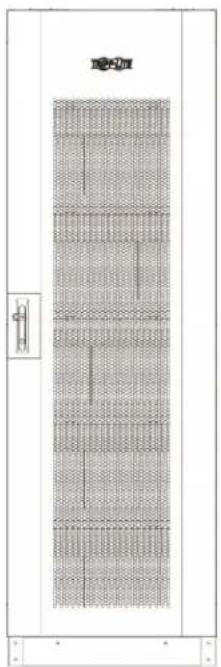
Dimensions (H x W x D): 2005 x 647 x 1100 mm
Empty Cabinet Weight: 487 lb. / 221 kg

W

natural_image
Technical line drawing of a door with mesh pattern and door label (no readable text or symbols)FRONT VIEW
D

SIDE VIEW REAR VIEW

natural_image
Technical line drawing of a door with mesh pattern and control panel (no text or symbols)6. Mechanical Data


FRONT VIEW SIDE VIEW REAR VIEW
6.2 Battery Requirements
Lead-Acid Cell Type and Quantity: 12V 100Ah x 40 Batteries
Lead-Acid Battery Maximum Size (H x W x D): 224 x 173 x 343 mm
Terminal Type: M6 Bolt
Terminal Torque (applies to CSB GPL 121000 model): 138.6 kgf·cm/13.58 N·m

7. Installation

Battery installation should only be performed by qualified service personnel.
7.1 Battery Pre-Installation
Battery cabinet:
The "F" marks the front side of the battery cabinet; the "R" marks the rear side of battery cabinet.
Battery shelf structure:
The cabinet includes 6 shelves total from L1 (bottom) to L6 (top).

7. Installation
7.2 Cable Jumpers and Internal Wiring
7.2.1 Included Cable Jumpers Specifications
1/0 AWG double wire

| ITEM DESCRIPTION UNIT CABLE LENGTH (mm) QUANTITY CABLE NUMBER | ||||
| A UL 1015#11/OAWG BLACK mm 250 28 | 1 | |||
| A UL 1015#11/OAWG BLACK mm 300 6 | 2 | |||
| A UL 1015#11/OAWG BLACK mm 550 3 | 3 | |||
| A UL 1015#11/OAWG BLACK mm 850 1 | 4 | |||
| A UL 1015#11/OAWG BLACK mm 550 1 N | ||||
| A UL 1015#11/OAWG BLACK mm 800 1 N | ||||
| A UL 1015#11/OAWG BLACK mm 1250 1 BAT+ | ||||
| A UL 1015#11/OAWG BLACK mm 1200 1 BAT- | ||||
| B | L/W PVC UL1015 TS #1/0 BLK | PCS | — | 84 |
Distance between battery shelves

7. Installation
7.2.2 Battery Cabinet Internal Wiring

flowchart
graph TD
    A["Breaker on battery cabinet (Rated for 400A, 600V DC)"] --> B["Wiring to UPS"]
    B --> C["L1"]
    B --> D["L2"]
    B --> E["L3"]
    B --> F["L4"]
    B --> G["L5"]
    B --> H["L6"]
    style A fill:#f9f,stroke:#333
    style B fill:#ccf,stroke:#333
    style C fill:#cfc,stroke:#333
    style D fill:#cfc,stroke:#333
    style E fill:#cfc,stroke:#333
    style F fill:#cfc,stroke:#333
    style G fill:#cfc,stroke:#333
    style H fill:#cfc,stroke:#333
7. Installation
7.2.3 Battery Cabinet Parallel Installation

flowchart
graph TD
    subgraph L1
        A["Breaker on battery cabinet"] --> B["L3"]
        C["Breaker on battery cabinet"] --> D["L2"]
        E["Breaker on battery cabinet"] --> F["L4"]
        G["Breaker on battery cabinet"] --> H["L6"]
    end
    subgraph L2
        I["Breaker on battery cabinet"] --> J["L5"]
        K["Breaker on battery cabinet"] --> L["F"]
        M["Breaker on battery cabinet"] --> N["L4"]
    end
    subgraph L3
        O["Breaker on battery cabinet"] --> P["L6"]
        Q["Breaker on battery cabinet"] --> R["L5"]
        S["Breaker on battery cabinet"] --> T["L4"]
    end
    subgraph L4
        U["Breaker on battery cabinet"] --> V["L6"]
        W["Breaker on battery cabinet"] --> X["L5"]
        Y["Breaker on battery cabinet"] --> Z["L4"]
    end
    subgraph L5
        AA["Breaker on battery cabinet"] --> AB["L6"]
        AC["Breaker on battery cabinet"] --> AD["L5"]
        AE["Breaker on battery cabinet"] --> AF["L4"]
    end
    subgraph L6
        AG["Breaker on battery cabinet"] --> AH["L6"]
        AI["Breaker on battery cabinet"] --> AJ["L5"]
        AK["Breaker on battery cabinet"] --> AL["L4"]
    end
    subgraph TO UPS
        AM["TO UPS"] --> AN["BAT"]
    end
7. Installation
7.3 Battery Installation
- Pull out the latch from the front door hinge. Remove door.

natural_image
Technical line drawing of a server rack cabinet with an inset showing a close-up of the door and wall-mounted cable (no text or symbols present)- Unscrew the M4 screws (12 pcs.) with a Phillips screwdriver and remove the side panels.

natural_image
Technical line drawing of a server rack cabinet with multiple panels and ventilation grilles (no text or labels)7. Installation
- Unscrew the M6 screws (4 pcs.) from each battery tray. Remove all the battery trays from cabinet.

natural_image
Technical line drawing of a server rack cabinet with metal frame and ventilation slots (no text or symbols)- Battery installation in the battery cabinet will start from the bottom (L1) and end at the top (L6). See below right figure for internal wiring "L1". Reference the table and diagrams in Sections 7.1.1 and 7.2.2 for the appropriate wire jumper needed.

7. Installation
- Use the saved M6 screws to secure the battery tray for L2.

natural_image
Technical line drawing of a multi-level server rack cabinet with no visible text or symbols- See the below right diagram for internal wiring "L2". Reference the table and diagrams in Sections 7.1.1 and 7.2.2 for the appropriate wire jumper needed.

7. Installation
- Use the saved M6 screws to secure the next battery tray for L3.

natural_image
Technical line drawing of a multi-level server rack cabinet with visible internal compartments and mounting base (no text or labels)- See the below right diagram for internal wiring "L3". Reference the table and diagrams in Sections 7.1.1 and 7.2.2 for the appropriate wire jumper needed.

7. Installation
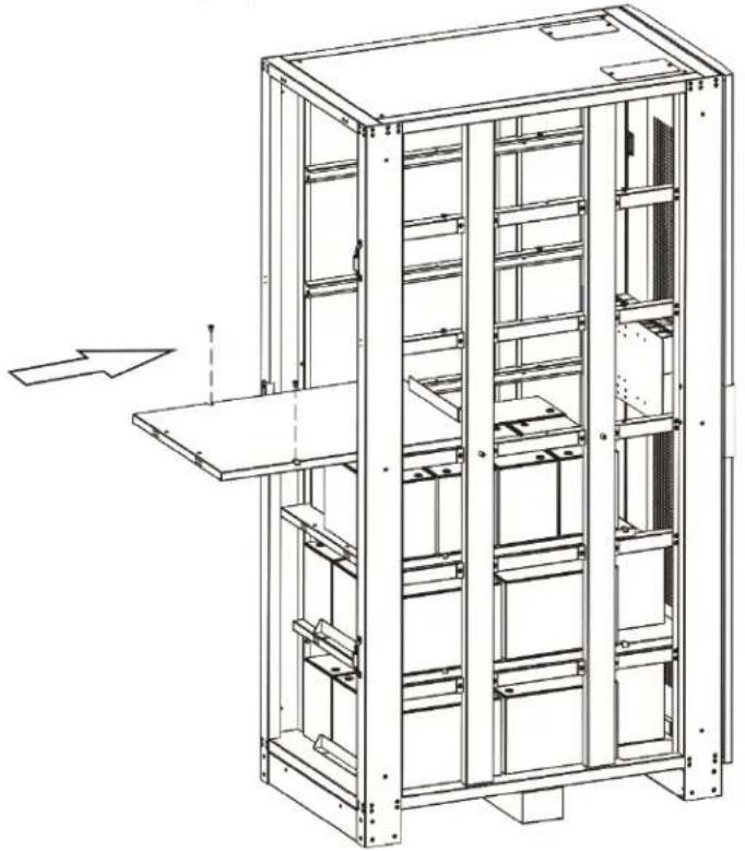
- Use the saved M6 screws to secure the next battery tray for L4.
natural_image
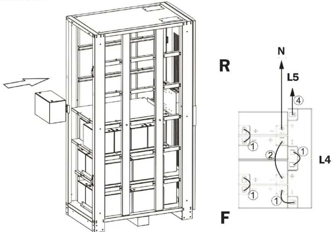
Technical line drawing of a multi-level industrial storage unit with structural beams and a central platform (no text or symbols)- See the below right diagram for internal wiring "L4". Reference the table and diagrams in Sections 7.1.1 and 7.2.2 for the appropriate wire jumper needed.
7. Installation
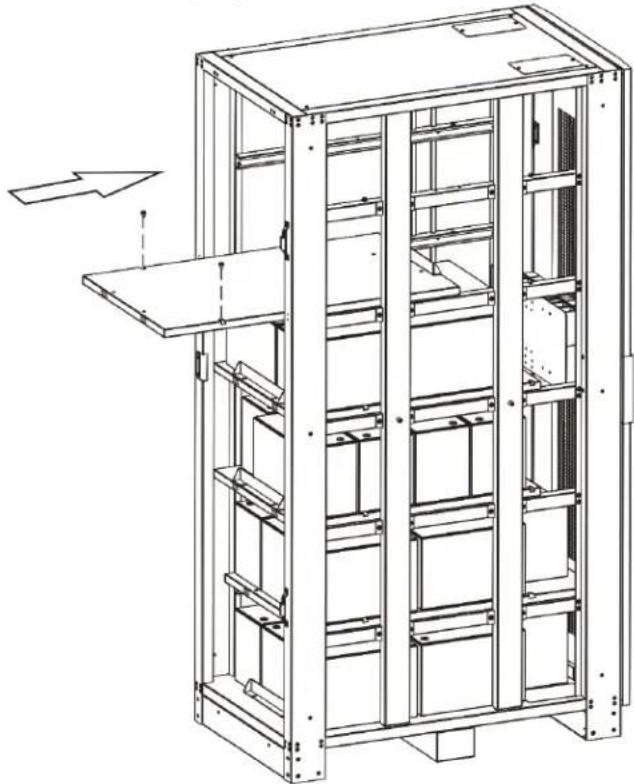
- Use the saved M6 screws to secure the next battery tray for L5.
natural_image
Technical line drawing of a multi-level industrial storage unit with structural beams and a central shelf (no text or symbols)- See the below right diagram for internal wiring "L5". Reference the table and diagrams in Sections 7.1.1 and 7.2.2 for the appropriate wire jumper needed.

natural_image
Technical line drawing of a multi-level server rack cabinet with mounting base and internal compartments (no text or labels)
7. Installation
- Use the saved M6 screws to secure the next battery tray for L6.

natural_image
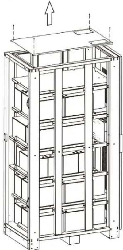
Technical line drawing of a multi-level industrial storage unit with shelves and structural supports (no text or symbols)- Remove the M4 screws (4 pcs.) from cabinet top cover and remove.
natural_image
Technical line drawing of a multi-level industrial storage unit with structural framework and mounting brackets (no text or symbols)7. Installation
- See the below right diagram for internal wiring "L6". Reference the table and diagrams in Sections 7.1.1 and 7.2.2 for the appropriate wire jumper needed.

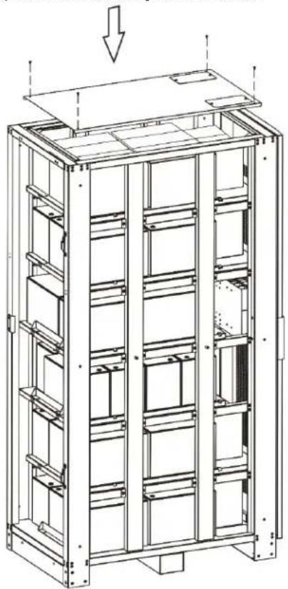
- Use M4 screws to reinstall and secure the top cover to the battery cabinet frame.
natural_image
Technical line drawing of a multi-level industrial storage unit with structural framework and mounting base (no text or symbols)7. Installation
- Use the saved M4 screws to reinstall and secure the side panels to the battery cabinet frame.

natural_image
Technical line drawing of a server rack cabinet with multiple panels and ventilation grilles (no text or labels)- Reinstall the front door and reinsert the latch to the door hinge.

natural_image
Technical line drawing of a server rack cabinet with internal panel and door, showing structural details and mounting bracket (no text or symbols)7. Installation
7.4. Installation Specifications
7.4.1 Installation and Floor Loading Information
| Battery Cabinet Model Shelves Dimensions (Height x Width x Depth) Casters Weight Floor Load | |||||
| BP480V370 6 2005 x 650 | x 1100 mm N | 1606 kg 1187 kg/m | ^2 | ||
| BP480V370NB 6 2005 x 650 | x 1100 mm | N 266 kg 1187 kg/m | ^2 | ||
7.4.2 Recommended Torque
| Battery Cabinet Model | Individual Battery Unit Model | Terminal Type | Torque |
| BP480V370 | CSB GPL 121000 | M6 Threaded Insert | 138.6 kgf•cm/120.3 lbf•in/13.58 N•m |
| BP480V370NB | N/A | N/A | N/A |
8. Storage and Service
Storage
The battery cabinet must be stored in a clean, secure environment with a temperature less than 40^ C ( 104^ F) and a relative humidity less than 90% (non-condensing). Store the battery cabinet in its original shipping container if possible. Charge the batteries for at least 24 hours prior to use. Do not rely on the battery cabinet to provide backup power to connected equipment until the batteries are fully charged.
Note: If the UPS system remains off for an extended period of time, it should be turned on periodically to allow the batteries to recharge. The UPS system should be turned on and the batteries should be recharged at least one uninterrupted 24-hour period every 3 months. Failure to recharge the batteries periodically may cause irreversible battery damage.
Service
Your Tripp Lite product is covered by the warranty described in this manual. A variety of Extended Warranty and On-Site Service Programs are also available from Tripp Lite. For more information on service, visit www.triplite.com/support. Before returning your product for service, follow these steps:
- Review the installation and operation procedures in this manual to insure that the service problem does not originate from a misreading of the instructions.
- If the problem continues, do not contact or return the product to the dealer. Instead, visit www.tripplite.com/support.
- If the problem requires service, visit www.triplite.com/support and click the Product Returns link. From here you can request a Returned Material Authorization (RMA) number, which is required for service. This simple on-line form will ask for your unit's model and serial numbers, along with other general purchaser information. The RMA number, along with shipping instructions will be emailed to you. Any damages (direct, indirect, special or consequential) to the product incurred during shipment to Tripp Lite or an authorized Tripp Lite service center are not covered under warranty. Products shipped to Tripp Lite or an authorized Tripp Lite service center must have transportation charges prepaid. Mark the RMA number on the outside of the package. If the product is within its warranty period, enclose a copy of your sales receipt. Return the product for service using an insured carrier to the address given to you when you request the RMA.
9. Warranty and Product Registration
Limited Warranty
Seller warrants this product, if used in accordance with all applicable instructions, to be free from original defects in material and workmanship for a period of 1 year from the date of initial purchase. If the product should prove defective in material or workmanship within that period, Seller will repair or replace the product, in its sole discretion. Service under this Warranty includes parts and Tripp Lite service center labor. On-site service plans are available from Tripp Lite through authorized service partners (in most areas). Visit www.triplite.com/support for details. International customers should contact Tripp Lite support at intlservice@tripplite.com.
THIS WARRANTY DOES NOT APPLY TO NORMAL WEAR OR TO DAMAGE RESULTING FROM ACCIDENT, MISUSE, ABUSE OR NEGLECT. SELLER MAKES NO EXPRESS WARRANTIES OTHER THAN THE WARRANTY EXPRESSLY SET FORTH HEREIN. EXCEPT TO THE EXTENT PROHIBITED BY APPLICABLE LAW, ALL IMPLIED WARRANTIES, INCLUDING ALL WARRANTIES OF MERCHANTABILITY OR FITNESS, ARE LIMITED IN DURATION TO THE WARRANTY PERIOD SET FORTH ABOVE; AND THIS WARRANTY EXPRESSLY EXCLUDES ALL INCIDENTAL AND CONSEQUENTIAL DAMAGES. (Some states do not allow limitations on how long an implied warranty lasts, and some states do not allow the exclusion or limitation of incidental or consequential damages, so the above limitations or exclusions may not apply to you. This Warranty gives you specific legal rights, and you may have other rights which vary from jurisdiction to jurisdiction.)
Tripp Lite; 1111 W. 35th Street; Chicago IL 60609; USA
WARNING: The individual user should take care to determine prior to use whether this device is suitable, adequate or safe for the use intended. Since individual applications are subject to great variation, the manufacturer makes no representation or warranty as to the suitability or fitness of these devices for any specific application.
Product Registration
Visit www.triplite.com/warranty today to register your new Tripp Lite product. You'll be automatically entered into a drawing for a chance to win a FREE Tripp Lite product.*
* No purchase necessary. Void where prohibited. Some restrictions apply. See website for details.
Regulatory Compliance Identification Numbers
For the purpose of regulatory compliance certifications and identification, your Tripp Lite product has been assigned a unique series number. The series number can be found on the product nameplate label, along with all required approval markings and information. When requesting compliance information for this product, always refer to the series number. The series number should not be confused with the marketing name or model number of the product.
Tripp Lite has a policy of continuous improvement. Specifications are subject to change without notice.


1111 W. 35th Street, Chicago, IL 60609 USA • www.tripplite.com/support
natural_image
Architectural elevation drawing of a double door with grid pattern and door handle (no text or symbols)

natural_image
Technical line drawing of a door with grid pattern and control panel (no text or symbols)VISTA FRONTAL

natural_image
Technical diagram of a multi-panel server rack with labeled dimension (AI), showing internal grid layout and mounting points (no text or symbols beyond label)VISTA LATERAL VISTA POSTERIOR

natural_image
Technical line drawing of a vertical panel with grid pattern and a small inset component (no text or symbols)6. Datos Mecánicos


VISTA FRONTAL VISTA LATERAL VISTA POSTERIOR
| ÍTEM DESCRIPCIÓN UNIDAD LONGITUD DE CABLE | (mm) CANTIDAD NÚMERO DE CABLE | ||
| A UL 1015#11 / 0 AWG NEGRO mm 250 28 | 1 | ||
| A UL 1015#11 / 0 AWG NEGRO mm 300 6 | 2 | ||
| A UL 1015#11 / 0 AWG NEGRO mm 550 3 | 3 | ||
| A UL 1015#11 / 0 AWG NEGRO mm 850 1 | 4 | ||
| A UL 1015#11 / 0 AWG NEGRO mm 550 1 N | |||
| A UL 1015#11 / 0 AWG NEGRO mm 800 1 N | |||
| A UL 1015#11 / 0 AWG NEGRO mm 1250 1 BAT+ | |||
| A UL 1015#11 / 0 AWG NEGRO mm 1200 1 BAT- | |||
| B L/W PVC UL1015 TS #1/0 NEGRO | PIEZAS — | 84 | — |
natural_image
Technical line drawing of a server rack cabinet with an inset showing a close-up of the door panel (no text or symbols present)natural_image
Technical line drawing of a server rack cabinet with multiple panels and ventilation grilles (no text or labels)7. Instalación
natural_image
Technical line drawing of a server rack cabinet with metal frame and ventilation slots (no text or symbols)7. Instalación
natural_image
Technical line drawing of a multi-level server rack cabinet with no visible text or symbols7. Instalación
natural_image
Technical line drawing of a multi-level server rack cabinet with visible internal compartments and mounting base (no text or labels)7. Instalación
natural_image
Technical line drawing of a multi-level industrial storage unit with structural beams and a central platform (no text or symbols)7. Instalación
natural_image
Technical line drawing of a multi-level industrial storage unit with structural beams and a central shelf (no text or symbols)natural_image
Technical line drawing of a multi-level industrial storage unit with shelves and structural supports (no text or symbols)natural_image
Technical line drawing of a multi-level industrial storage unit with structural framework and upward arrow indicator (no text or symbols)7. Instalación
natural_image
Technical line drawing of a multi-level industrial storage unit with structural framework and mounting base (no text or symbols)7. Instalación
natural_image
Technical line drawing of a server rack cabinet with multiple panels and ventilation grilles (no text or labels)natural_image
Technical line drawing of a server rack cabinet with an inset showing internal components (no text or symbols)7. Instalación
natural_image
Architectural elevation drawing of a double door with grid pattern and door handle (no text or symbols)

1111 W. 35th Street, Chicago, IL 60609 USA • www.tripplite.com/support
natural_image
Technical line drawing of a door frame with grid pattern and a small inset component (no text or symbols)natural_image
Technical line drawing of a server rack cabinet with an inset showing a close-up of the interior panel (no text or symbols present)natural_image
Technical line drawing of a server rack cabinet with multiple panels and ventilation grilles (no text or labels)7. Установка
natural_image
Technical line drawing of a multi-level server rack cabinet with no visible text or symbolsnatural_image
Technical line drawing of a server rack cabinet with internal compartments and mounting base (no text or symbols)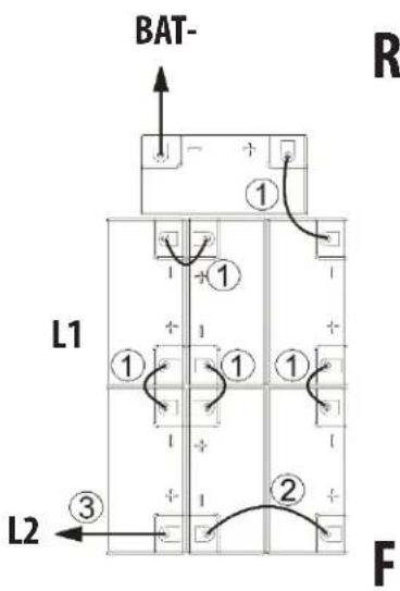
7. Установка
natural_image
Technical line drawing of a multi-level industrial storage unit with structural beams and a central platform (no text or symbols)natural_image
Technical line drawing of a multi-level industrial storage unit with internal compartments and a directional arrow indicating motion (no text or symbols)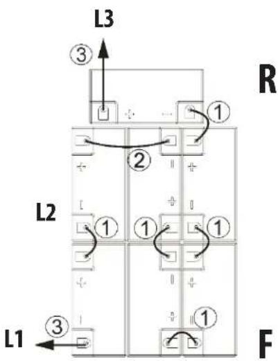
7. Установка
natural_image
Technical line drawing of a multi-level server rack cabinet with visible internal compartments and mounting base (no text or labels)7. Установка
natural_image
Technical line drawing of a multi-level server rack cabinet with visible shelves and mounting brackets (no text or labels)natural_image
Technical line drawing of a multi-level server rack cabinet with internal compartments and mounting base (no text or labels)R

F
7. Установка
natural_image
Technical line drawing of a multi-level industrial storage unit with visible shelves and structural supports (no text or symbols)natural_image
Technical line drawing of a multi-level server rack cabinet with mounting base and internal compartments (no text or labels)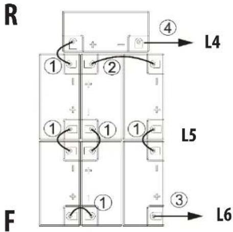
7. Установка
natural_image
Technical line drawing of a multi-level industrial storage unit with shelves and structural supports (no text or symbols)natural_image
Technical line drawing of a multi-level industrial storage unit with structural framework and upward arrow indicator (no text or symbols)7. Установка
natural_image
Technical line drawing of a multi-level industrial storage unit with structural framework and mounting base (no text or symbols)7. Установка
natural_image
Technical line drawing of a server rack cabinet with multiple panels and ventilation grilles (no text or labels)natural_image
Technical line drawing of a server rack cabinet with internal panel and door, showing structural details and mounting bracket (no text or symbols)7. Установка
1111 W. 35th Street, Chicago, IL 60609 USA • www.tripplite.com/support


- Extended-Run Battery Cabinet
- Table of Contents
- Introduction 2
- Important Safety Instructions 3
- Battery Cabinet Installation 4
- Operation and Charging
- Maintenance 7
- Mechanical Data 8
- Installation 10
- Storage and Service 23
- Warranty and Product Registration 24
- Español 25
- Русский 49
- Introduction
- Features
- Important Safety Instructions
- SAVE THESE INSTRUCTIONS
- DANGER! LETHAL HIGH VOLTAGE HAZARD!
- Installation and Location Warnings
- Connection Warnings
- Battery Warnings
- Note on Labeling
- Battery Cabinet Installation
- Read Section 2 – Important Safety Instructions Before Installation
- Preparation
- Transportation
- Mechanical Check
- Internal Wiring (Typical)
- Preliminary Electrical Check (After Battery Installation)
- Battery Cabinet Placement
- Electrical Connection
- After performing the installation procedures in Section 7.:
- Final Electrical Check
- Determine Charging Voltages
- For example:
- Initial Charge
- Operational Check
- Maintenance
- Maintenance Schedule
- Quarterly Check
- Mechanical Data
- Physical Measurements
- Battery Requirements
- Installation
- Battery installation should only be performed by qualified service personnel.
- Battery Pre-Installation
- Cable Jumpers and Internal Wiring
- Included Cable Jumpers Specifications
- Battery Installation
- Installation Specifications
- Installation and Floor Loading Information
- Recommended Torque
- Storage and Service
- Storage
- Service
- Warranty and Product Registration
- Limited Warranty
- Product Registration
- Regulatory Compliance Identification Numbers
- Datos Mecánicos
- Instalación
- Установка
Brand : Tripp Lite
Model : BP480V370NB
Category : UPS