
SmartOnline Expandable - UPS Tripp Lite - Free user manual and instructions
Find the device manual for free SmartOnline Expandable Tripp Lite in PDF.


| Product Type | Rack/Tower Mount Online UPS |
| Model Series | SmartOnline Expandable |
| Input Voltage Range (Full Load) | 80-138V (120V models) / 160-275V (208/230V models) |
| Output Voltage | 120V, 208V, or 230V depending on model |
| Output Capacity (VA/Watts) | Up to 3000/2400 depending on model |
| Output Waveform | Pure Sine Wave (Line and Battery Modes) |
| Transfer Time | 0 ns (instantaneous) |
| Battery Type | Sealed Lead-Acid (replaceable) |
| System Battery Voltage | 36VDC, 48VDC, or 72VDC depending on model |
| Battery Runtime (Half Load/Full Load) | Typically 14-18 min / 5-6 min depending on model |
| Battery Recharge Time to 80% | 2-4 hours |
| Input Frequency | 50/60 Hz (auto-selecting) |
| Approvals | UL, cUL, FCC, NOM (varies by model; some models CE) |
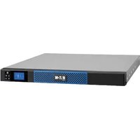
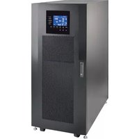
| Mounting | Rackmount (2U) or Vertical Tower |
| Communication Ports | DB9 Serial (RS-232 / Dry Contact / EPO) |
| Accessory Slot | For optional SNMP/network management cards |
| External Battery Connector | For optional external battery packs |
| Input Plug Types | 5-15P, 5-20P, L5-30P, 6-15P, 6-20P, L6-20P, IEC C14, C20 (model dependent) |
| Output Receptacles | NEMA 5-15R, 5-15/20R (varies by model) |
| Operating Temperature | 32°F to 104°F (0°C to 40°C) |
| Safety Features | Overload protection, short circuit protection, wiring fault detection, internal fault alerts |
| Maintenance | No routine maintenance required; battery replacement by qualified personnel only |
| Warranty | 2 years |
Frequently Asked Questions - SmartOnline Expandable Tripp Lite
User questions about SmartOnline Expandable Tripp Lite
0 question about this device. Answer the ones you know or ask your own.
Ask a new question about this device
Download the instructions for your UPS in PDF format for free! Find your manual SmartOnline Expandable - Tripp Lite and take your electronic device back in hand. On this page are published all the documents necessary for the use of your device. SmartOnline Expandable by Tripp Lite.
USER MANUAL SmartOnline Expandable Tripp Lite
Rack/Tower Mount Online UPS Systems

US


Important Safety Instructions 2
Installation 3
Basic Operation 6
Troubleshooting 10
Battery Replacement 12
Storage and Service 14
Specifications 14
Español 16
Français 31
Русский 46

1111 W. 35th Street Chicago, IL 60609 USA
Customer Support: (773) 869-1234 • www.tripplite.com
SAVE THESE INSTRUCTIONS
This manual contains instructions and warnings that should be followed during the installation, operation and storage of all Tripp Lite UPS Systems. Failure to heed these warnings will void your warranty.
UPS Location Warnings
• Install your UPS indoors, away from excess moisture or heat, conductive contaminants, dust or direct sunlight.
- For best performance, keep the indoor temperature between between 32ircF and 104ircF (0ircC and 40ircC) .
- Leave adequate space around all sides of the UPS for proper ventilation.
UPS Connection Warnings
- Connect your UPS directly to a properly grounded AC power outlet. Do not plug the UPS into itself; this will damage the UPS.
- Do not modify the UPS's plug, and do not use an adapter that would eliminate the UPS's ground connection.
- Do not use extension cords to connect the UPS to an AC outlet. Your warranty will be voided if anything other than Tripp Lite surge suppressors are used to connect your UPS to an outlet.
- If the UPS receives power from a motor-powered AC generator, the generator must provide clean, filtered, computer-grade output.
Equipment Connection Warnings
- Do not use Tripp Lite UPS Systems for life support applications in which a malfunction or failure of a Tripp Lite UPS System could cause failure or significantly alter the performance of a life-support device.
- Do not connect surge suppressors or extension cords to the output of your UPS. This might damage the UPS and will void the surge suppressor and UPS warranties.
Battery Warnings
- Your UPS does not require routine maintenance. Do not open your UPS for any reason except battery replacement. There are no user-serviceable parts inside.
- Battery replacement must be performed by qualified service personnel. Because the batteries present a risk of electrical shock and burn from high short-circuit current, observe proper precautions. Unplug and turn off the UPS before performing battery replacement. Use tools with insulated handles, and replace the existing batteries with the same number and type of new batteries (Sealed Lead-Acid). Do not open the batteries. Do not short or bridge the battery terminals with any object.
- The UPS batteries are recyclable. Refer to local codes for disposal requirements, or in the USA only call 1-800-SAV-LEAD for recycling information. Do not dispose of the batteries in a fire.
- Only connect Tripp Lite battery packs of the appropriate type and correct voltage to the external battery connector.
- Do not connect or disconnect external batteries while the UPS is operating from battery.
- Do not operate your UPS without batteries.
Installation
Mounting
Rackmount
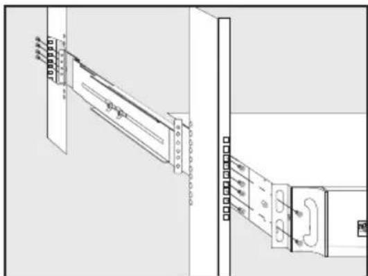
1) Loosen the wingnuts on each of the two UPS Side Supports; adjust the length of the supports to match the depth of your rack; tighten wingnuts.
2) Mount both UPS Side Supports in your rack on the inside surfaces of the rack rails.
Note: Both support ledges should face inward. The side supports front and back holes are threaded and do not require nuts to secure rack bolts.
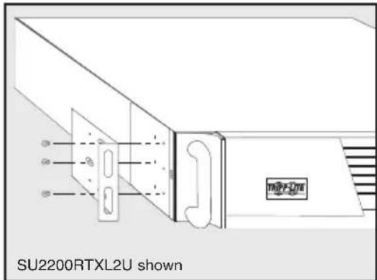
3) Attach mounting ‘ears’ to the front end of the UPS’s sides using the screws provided.
4) Lift UPS and slide it onto the UPS Side Supports within your rack. Mount the UPS by screwing rack bolts through the UPS mounting 'ears', through the rack rails and through the UPS Side Supports.
Note: The side supports' front holes are threaded and do not require nuts to secure rack bolts.
Vertical Tower Mount
1) Cover the rackmount screw holes on the UPS's sides with supplied snap-in hole-cover caps.
2) Place the UPS upright in a flat, stable location with its control panel on the high corner facing forward. Position stabilizer feet 4 in. from each end of the UPS.
natural_image
Technical line drawing of a door frame assembly with mounting bracket and door handle (no text or symbols)
natural_image
Technical line drawing of a server rack unit with mounting brackets and ventilation cover (no text or symbols on the diagram itself)Connection and Start-Up
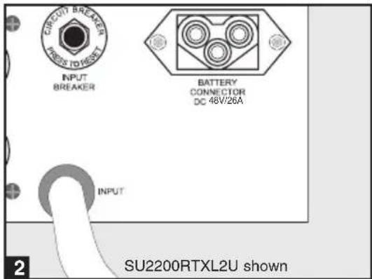
1 Plug your UPS's line cord into an electrical outlet.
If your model features a detachable line cord, first plug the female end into your UPS's AC Input Receptacle.
Your UPS must be connected to a dedicated circuit of sufficient amperage—check the “Recommended Utility Amps” rating of your model in the specifications. Note, however, that the select models may be fitted with different plug types. Refer to the “OP Rating/Plug Rating” chart printed on the top of your UPS.
Once your UPS is plugged in, the fan and all Indicator Lights will turn ON. The “LINE” and “LOAD ACTIVE METER” LEDs will illuminate and the UPS will emit a beep to indicate normal operation. However, power is not supplied to your UPS’s AC outlets until the UPS is turned on.
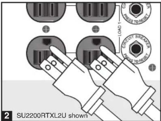
2 Plug your equipment into your UPS.
Your UPS is designed to support computer equipment only. You will overload your UPS if you connect household appliances or laser printers to the UPS's outlets.
3 Turn your UPS ON:
- Press the "ON/TEST" Switch
- Hold it for several seconds until you hear a beep
- Release it
Your UPS will begin providing AC power to its outlets. The "ON LINE" LED will illuminate.


Installation (continued)
Optional Connections
Your UPS will function properly without these connections.
1 Serial Port Connection
Using the serial cable provided, connect a serial port on your computer to the serial port of your UPS. See Communications in the Basic Operation section of this manual to determine how to monitor and manage your UPS using this port.
2 External Battery Pack Connection
Check to ensure that the external batteries you are connecting match the voltage listed on your UPS's battery connector. Plug either end of the battery connection cable (supplied with the battery pack) into the UPS's External Battery Connector and the other end into the Battery Output Connector on the rear panel of the external battery pack.
Since your UPS has internal batteries, external batteries are only needed to extend runtime. Adding external batteries will increase recharge time as well as runtime. Make sure that each end of the cable is fully inserted into its connector. Several small sparks may result during battery connection; this is normal.

Front Panel Switches

"ON/TEST" Switch: This switch controls four separate UPS functions:
UPS Power ON
To turn the UPS on, press this switch, hold it for several seconds until you hear a beep, then release it. The “ON LINE” LED will illuminate.
UPS Self-Test
During normal on-line operation, press this switch and hold it until you hear a beep. This initiates a 10-second self-test of the battery. The UPS will shift to battery power (the “ON BATT” and “BATT ACTIVE METER” LEDs will illuminate) for ten seconds.
Alarm Silence
To silence the UPS “on-battery” alarm, press this switch and hold it until you hear a beep.
UPS Cold Start
To use your UPS as a stand-alone power source when AC power is unavailable (i.e. during a blackout), press this switch and hold it until you hear a beep. The UPS will then provide battery power to its outlets.*
* The “ON BATT” Indicator Light will be illuminated since your UPS will be operating from battery power.
“OFF” Switch: This switch turns power OFF at the UPS receptacles. Press this switch, hold it until you hear a beep, then release it. The UPS will continue charging and the fan will continue to cool internal components even after you turn the UPS receptacles off. To turn the UPS OFF completely, including the charger, disconnect the UPS’s power cord after pressing the “OFF” switch.
Front Panel Indicator Lights

“ON LINE” LED: This green light will illuminate constantly to indicate the UPS is performing normal on-line operation (filtering and resynthesizing incoming AC line voltage to provide pure sine wave output). When this light is illuminated, you can monitor the load level of your UPS on the “LOAD ACTIVE METER” LEDs.

“LINE” LED: This green light will illuminate constantly to indicate the utility supplied AC line voltage at your wall outlet is nominal. It will flash if the line voltage is outside the nominal range (either too low or two high). No action is required on your part when the LED flashes; the UPS continuously and automatically filters AC line power to provide your equipment with pure sine wave AC power, regardless of brownout or overvoltage conditions. If this light is off, then AC line voltage is not present (blackout) or is at an extremely high voltage, and the UPS will provide connected equipment with power from battery.
Basic Operation (continued)
Front Panel Indicator Lights continued

"BYPASS" LED: This yellow light will illuminate to indicate that the UPS's DC/AC inverter is deactivated and the UPS is in the "Bypass" mode. During normal operation this LED will light briefly when the unit is plugged in, but if an internal fault or overload occurs this light will illuminate constantly to show that connected equipment will receive filtered AC mains power, but will not receive battery power during a blackout. In this case, contact Tripp Lite for service.

“FAULT” LED: This red light will flash when your UPS detects an internal fault (overheating, overvoltages, etc.) or when it detects a wiring fault in your wall outlet (reversed phases, missing ground, etc.) The UPS will only detect wiring faults when it is plugged into a utility outlet but not turned ON. If the light persists after restarting the UPS, contact an electrician to check the AC line. Your UPS will identify the presence of most (but not all) wiring faults.

"LOAD ACTIVE METER" LED: This green light will illuminate when your UPS is receiving AC power to indicate that the set of four dual-function LEDs is displaying the load level of your UPS.

"BATT ACTIVE METER" LED: This green light will illuminate when your UPS is operating from battery power to indicate that the set of four dual-function LEDs is displaying the battery charge level of your UPS. Note: the "ON BATT" LED will also be illuminated.

"OVERLOAD" LED: This red light will illuminate constantly to indicate that your UPS's capacity has been exceeded while it is in on-line operation. The UPS alarm will beep continuously. Immediately remove overload until light and alarm goes off. If you do not immediately remove the overload, the UPS will transfer from on-line to bypass operation.

"BATT LOW" LED: This yellow light will illuminate when your UPS's battery charge level is low. The UPS alarm will beep until either the battery charge is depleted or the batteries are adequately recharged.

“ON BATT” LED: This green light will illuminate constantly to indicate that AC line voltage is not present and your UPS is providing your equipment with battery power. The UPS will also beep every two seconds, unless silenced by the “ON/TEST” Switch. When this light is illuminated, you can monitor the battery charge level of your UPS on the “BATT ACTIVE METER” LEDs.
Front Panel Indicator Lights continued

"REPLACE BATT" LED: This red light will illuminate constantly and the UPS alarm will sound three beeps* if your UPS's microprocessor detects a battery fault or if your UPS fails the automatic self-test (after you turn your UPS ON) and the UPS battery is less than fully charged. Let the UPS system charge for at least 12 hours and perform a self test using the "ON/Test Switch" as described on page 6. If the light continues to stay on, contact Tripp Lite for service.
*After the initial alarm, the UPS will beep once every hour until the problem is corrected.
Rear Panel

Accessory Slot: Remove the small cover panel from this slot to use optional accessories to remotely monitor and control your UPS. Contact Tripp Lite Customer Support at (773) 869-1234 for more information, including a list of available SNMP, network management and connectivity products.
natural_image
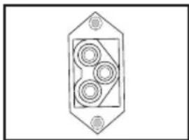
Pure electrical circuit lines without any symbolsExternal Battery Pack Connector: Use to connect optional Tripp Lite Battery Packs for additional runtime. Contact Tripp Lite Customer Support at (773) 869-1234 for the appropriate Tripp Lite battery pack to connect. Refer to instructions available with the Battery Pack for complete connection information and safety warnings.
natural_image
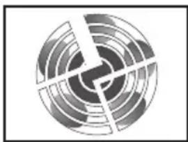
Abstract circular pattern with concentric rings and radial lines, no text or symbols presentFan: The fan cools the UPS's internal components. It is always on when line power is present.

natural_image
Simple rectangular diagram with two small cross symbols at the bottom corners (no text or labels)TVSS Cover Plate: Remove this plate to install optional modem/network surge protection modules, available for purchase by special arrangement with Tripp Lite.

Input Circuit Breaker Switch: This resettable breaker prevents high input current from damaging the UPS or the attached load. If this breaker trips, make sure your UPS is connected to AC power of the proper voltage before resetting the circuit breaker by pushing the breaker switch in.
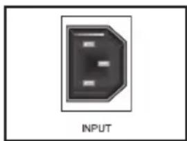
Input Receptacle (Select Models Only): Connect one end of the detachable line cord into this receptacle and the other into your wall outlet.
Basic Operation (continued)
Rear Panel continued
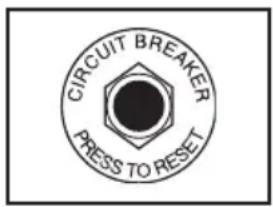
Output Circuit Breakers Switches (Select Models Only): These resettable circuit breakers protect your UPS from output overload. If one or both breakers trip, remove some of the load on the circuit(s) and allow the UPS to cool before pressing the breaker switch(es) in to reset.

Input Cord (Select Models Only): This permanently attached power cord connects your UPS to a power outlet.
natural_image
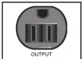
Circular device with three vertical slots and a labeled 'OUTPUT' button (no other text or symbols)NEMA 5-15R

NEMA 5-15/20R
Other outlet types not shown
AC Receptacles (Varied by Model): These 15-, 20- and 30-amp receptacles provide your connected equipment with pure sine-wave AC output from the AC line during normal operation and from battery power during blackouts and severe brownouts. Power provided at these outlets is filtered to protect connected equipment against damaging surges and line noise. The receptacles are divided into numbered load banks, as labelled on the unit. Using PowerAlert software and cabling, load banks one and two may be individually turned off and on from a remote location, allowing users to reset or reboot connected equipment. See Serial Port Connection under Optional Connections.
Communications
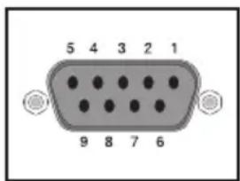
"SMART" DB9 Port: Your UPS's DB9 port can be used to monitor and control your UPS using either RS-232 or dry contact protocols. It can also be used to connect an emergency power off (EPO) switch.
RS-232 communications are very complex, but are easy to implement. The easiest way monitor and control the UPS using RS-232 is to connect the UPS to a computer with a DB9 cable and install Tripp Lite's PowerAlert software on the connected computer.
Dry contact communications are simple, but some knowledge of electronics is necessary to configure them. The DB9 port's pin assignments are shown in the diagram at the left. If the UPS battery is low, the UPS sends a signal by bridging pin 1 and pin 5. If utility power fails, the UPS sends a signal by bridging pin 8 and pin 5. To shut the UPS down remotely, send a 5V to 12V signal on pin 3 (using pin 5 as the (negative) ground) for at least 3.8 seconds.
You may connect your UPS to an EPO switch and a computer at once using a Tripp Lite EPO cable (not included; order accessory #73-0901 from Tripp Lite). Follow the connection procedures included with the EPO Cable.
Troubleshooting
The UPS's control panel lights will turn on in the sequences below to signal that the UPS is having operational difficulties.
Lights (On/Flashing) and Condition Solution
| On: REPLACE BATTCondition: Replace Battery 12 hours and perform a self test using the "ON/Test Switch" as described on page 6. If the light continues to stay on, contact Tripp Lite for service. | Let the UPS system charge for at least |
| On: BATT LOW, ON BATT Prepare for imminent UPS shutdown. Condition: Battery Low | |
| On: BYPASS, LINE, LOAD, OVERLOAD Condition: On Bypass due to Overload | Reduce the load the UPS supports. |
| On: FAULT Remove the cause of the short circuit Condition: Short Circuit from the UPS output. | |
| Flashing: FAULT Check the utility line for wiring problems Condition: Wiring Fault such as reversed line and neutral or a missing ground. | |
| On: FAULT, REPLACE BATT Condition: Battery Voltage too High | Restart the UPS. If the problem persists, contact Tripp Lite for repairs. |
| On: FAULT, REPLACE BATT, OVERLOAD Condition: EEPROM Error | Restart the UPS. If the problem persists, contact Tripp Lite for repairs. |
| On: FAULT, BYPASS, LINE, 100% Condition: On Bypass due to High Output Voltage | Restart the UPS. If the problem persists, contact Tripp Lite for repairs. |
| On: FAULT, BYPASS, LINE, 75% Condition: On Bypass due to Low Output Voltage | Restart the UPS. If the problem persists, contact Tripp Lite for repairs. |
| On: FAULT, BYPASS, LINE, 50% Condition: On Bypass due to High Bus Voltage | Restart the UPS. If the problem persists, contact Tripp Lite for repairs. |
| On: FAULT, BYPASS, LINE, 25% Condition: On Bypass due to Low Bus Voltage | Restart the UPS. If the problem persists, contact Tripp Lite for repairs. |
Lights (On/Flashing) and Condition Solution
| On: FAULT, BYPASS, LINE, 100%, 75%Condition: On Bypass due to High adequate space for air to circulate near Internal Temperature the vents and that the fan is working properly. Restart the UPS. | |
| Flashing: LINE This indicates that utility power is too highCondition: Input Abnormal or low for the UPS to operate in BYPASS mode, so if an inverter failure occurs, the UPS will deliver no output. | |
| On: FAULT, 100%Flashing: LINE, BYPASS Condition: No Output due to High Output Voltage and Abnormal Input | Restart the UPS. If the problem persists, contact Tripp Lite for repairs. |
| Flashing: LINE, BYPASS On: FAULT, 75%Condition: No Output due to Low Output Voltage and Abnormal Input | Restart the UPS. If the problem persists, contact Tripp Lite for repairs. |
| Flashing: LINE, BYPASS On: FAULT, 50%Condition: No Output due to High Bus Voltage and Abnormal Input | Restart the UPS. If the problem persists, contact Tripp Lite for repairs. |
| Flashing: LINE, BYPASS On: FAULT, 25%Condition: No Output due to Low Bus Voltage and Abnormal Input | Restart the UPS. If the problem persists, contact Tripp Lite for repairs. |
| Flashing: LINE, BYPASS On: FAULT, 100%, 75%Condition: No Output due to High Internal Temperature and Abnormal Input | Check the UPS to be sure that there is adequate space for air to circulate near the vents and that the fan is working properly. Restart the UPS. If the problem persists, contact Tripp Lite for repairs. |
Battery Replacement
Under normal conditions, the original battery in your UPS will last several years. Contact Tripp Lite for information about replacement batteries.
Battery replacement should be performed only by qualified service personnel. The batteries are hot-swappable: it is not necessary to turn off or disconnect the UPS and its connected load to replace the UPS's batteries. However, when it is convenient to do so, service personnel may simplify the replacement procedure by turning power off at the UPS outlets by pressing the OFF switch to and disconnecting the UPS's power cord from the wall outlet.
When replacing the batteries on a SU1000RTXL2U, SU1000RTXL2UHV or SUINT1000RTXL2U, qualified service personnel should refer to “Battery Warnings” in the Safety section and follow this procedure:
1) Place the UPS horizontal with the Control Panel on the right side.
2) Remove both snap-on cover panels (A).
3) Unscrew and remove rack handle plates (B) on either side of the UPS.
4) Disconnect the microprocessor circuit board plug (C) located on the right side of the UPS.
5) Disconnect battery connectors (D). Note: while batteries are disconnected, the UPS will not provide battery backup in the event of a power outage.
6) Unscrew and remove the battery retaining bracket (E).
7) Grasp pull-tab and pull out sliding battery tray (F).
8) Make a detailed sketch of the batteries and the polarity, color and connection of all cables. Disconnect used batteries and dispose of them properly. Connect replacement batteries in exactly the way the original batteries were connected. Note: Small sparks arcing between battery connectors during battery replacement are normal. Reassemble the UPS by reversing steps 1-7. Note: you may not receive full runtime until your new batteries have fully charged.

Battery Replacement (continued)
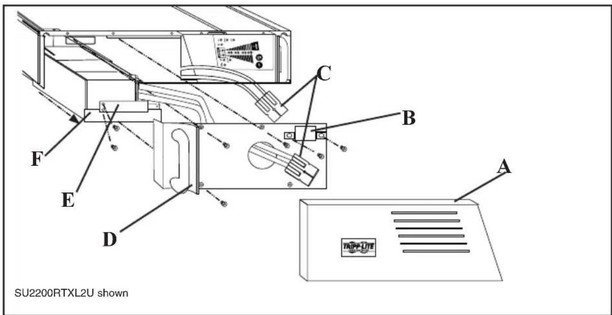
When replacing the batteries on a SU1500RTXL2U, SU1500RTXL2UHV, SUINT1500RTXL2U, SU2200RTXL2U, SU2200RTXL2UHV, SUINT2200RTXL2U, SU3000RTXL2U, SU3000RTXL2UHV or SUINT3000RTXL2U, qualified service personnel should refer to "Battery Warnings" in the Safety section and follow this procedure:
1) Place the UPS horizontal with its control panel on the right side.
2) Remove the left snap-on cover panel (A).
3) Unscrew and remove the battery connector cover (B).
4) Disconnect battery connectors (C). Note: while batteries are disconnected, the UPS will not provide battery backup in the event of a power outage.
5) Unscrew and remove the battery cover plate (D).
6) Unscrew and remove the battery retaining bracket (E).
7) Grasp pull-tab and pull out sliding battery tray (F).
8) Make a detailed sketch of the batteries and the polarity, color and connection of all cables. Disconnect used batteries and dispose of them properly. Connect replacement batteries in exactly the way the original batteries were connected. Note: Small sparks arcing between battery connectors during battery replacement are normal. Reassemble the UPS by reversing steps 1-7. Note: you may not receive full runtime until your new batteries have fully charged.
Storage and Service
Storage
First turn your UPS OFF: press the “OFF” switch to turn power off at the UPS outlets, then disconnect the power cord from the wall outlet. Next, disconnect all equipment to avoid battery drain. If you plan on storing your UPS for an extended period of time, fully recharge the UPS batteries once every three months by plugging the UPS into a live AC outlet and letting the UPS charge for 4-6 hours. If you leave your UPS batteries discharged for an extended period of time, they may suffer permanent loss of capacity.
Service
If returning your UPS to Tripp Lite, please carefully pack the UPS using the ORIGINAL PACKING MATERIAL that came with the unit. Enclose a letter describing the symptoms of the problem. If the UPS is within the 2 year warranty period, enclose a copy of your sales receipt.
Specifications
All Models: Input Frequency (50/60 Hz Auto-Selecting); Output Waveform in Line and Battery Modes (Pure Sine Wave); Transfer Time: (0 ns.); Maximum Harmonic Distortion with Linear Load ( ≤ 3%); Maximum Harmonic Distortion with Nonlinear Load ( ≤ 6%); Battery Recharge Time to 80% Capacity (2-4 hours).
Model SU1000RTXL2U SU1000RTXL2UHV SUINT1000RTXL2U
| Input Voltage (< 70% Load): 65-138V 130-275V 130-275V | |||
| Input Voltage (Full Load): 80-138V 160-275V 160-275V | |||
| Output Voltage: 120V 208V 230V | |||
| Input Breaker Rating: 15A | 8A | 8A | |
| Input Plug Type: | 5-15P | 6-15P | IEC 320-C14 |
| Recommended Utility Amps: | 15A | 15A | 10A |
| Output Capacity (VA/Watts): | 1000/800 | 1000/800 | 1000/800 |
| Battery Runtime (Half Load/Full Load) Min.: | 18/6 | 18/6 | 18/6 |
| System Battery Voltage: | 36 VDC | 36 VDC | 36 VDC |
| Approvals: | UL, cUL, FCC, NOM | UL, cUL, FCC, NOM | CE |
Model: SU1500RTXL2U SU1500RTXL2UHV SUINT1500RTXL2U
| Input Voltage (< 70% Load): 65-138V 130-275V 130-275V | |||
| Input Voltage (Full Load): 80-138V 160-275V 160-275V | |||
| Output Voltage: 120V 208V 230V | |||
| Input Breaker Rating: 20A | 10A | 10A | |
| Input Plug Type: | 5-15P | 6-20P | IEC 320-C14 |
| Recommended Utility Amps: | 20 A | 15 A | 15 A |
| Output Capacity (VA/Watts): | 1500/1200 | 1500/1200 | 1500/1200 |
| Battery Runtime (Half Load/Full Load) Min.: | 17/5 | 17/5 | 17/5 |
| System Battery Voltage: | 48 VDC | 48 VDC | 48 VDC |
| Approvals: | UL, cUL, FCC, NOM | UL,cUL, FCC, NOM CE | |
Model SU2200RTXL2U SU2200RTXL2UHV SUINT2200RTXL2U
| Input Voltage (< 70% Load): 65-138V 130-275V 130-275V | |||
| Input Voltage (Full Load): 80-138V 160-275V 160-275V | |||
| Output Voltage: 120V 208V 230V | |||
| Input Breaker Rating: 30A | 15A | 15A | |
| Input Plug Type: | 5-20P | 6-20P | IEC 320-C20 |
| Recommended Utility Amps: | 20A | 20A | 20A |
| Output Capacity (VA/Watts): | 2200/1600 | 2200/1600 | 2200/1600 |
| Battery Runtime (Half Load/Full Load) Min.: | 18/6 | 18/6 | 18/6 |
| System Battery Voltage: | 48 VDC | 48 VDC | 48 VDC |
| Approvals: | UL, cUL, FCC, NOM | UL, cUL, FCC, NOM | CE |
Specifications (continued)
Model SU3000RTXL3U SU3000RTXL3UHV SUINT3000RTXL3U
| Input Voltage (< 70% Load): 65-138V 130-275V 130-275V | |||
| Input Voltage (Full Load): 80-138V 160-275V 160-275V | |||
| Output Voltage: 120V 208V 230V | |||
| Input Breaker Rating: 40A 25A 25A | |||
| Input Plug Type: L5-30P | L6-20P | IEC 320-C20 | |
| Recommended Utility Amps: | 30A 20A 20A | ||
| Output Capacity (VA/Watts): 3000/2400 3000/2400 | 3000/2400 | ||
| Battery Runtime (Half Load/Full Load) Min.: | 14/6 | 14/6 14/6 | |
| System Battery Voltage: | 72 VDC | 72 VDC | 72 VDC |
| Approvals: | UL, cUL, FCC, NOM | UL, cUL, FCC, NOM | CE |
The policy of Tripp Lite is one of continuous improvement. Specifications are subject to change without notice.
FCC Specifications for Models with FCC Approval: This device complies with part 15 of the FCC Rules. Operation is subject to the following two conditions: (1) This device may not cause harmful interference, and (2) this device must accept any interference received, including interference that may cause undesired operation.
This equipment has been tested and found to comply with the limits for a Class A digital device, pursuant to part 15 of the FCC Rules. These limits are designed to provide reasonable protection against harmful interference when the equipment is operated in a commercial environment. This equipment generates, uses, and can radiate radio frequency energy and, if not installed and used in accordance with the instruction manual, may cause harmful interference to radio communications. Operation of this equipment in a residential area is likely to cause harmful interference in which case the user will be required to correct the interference at his own expense. The user must use shielded cables and connectors with this product. Any changes or modifications to this product not expressly approved by the party responsible for compliance could void the user's authority to operate the equipment.

1111 W. 35th Street, Chicago, IL 60609 USA 773.869.1234 (USA) • 773.869.1212 (International) www.tripplite.com


- SAVE THESE INSTRUCTIONS
- UPS Location Warnings
- UPS Connection Warnings
- Equipment Connection Warnings
- Battery Warnings
- Installation
- Mounting
- Rackmount
- Vertical Tower Mount
- Connection and Start-Up
- Plug your UPS's line cord into an electrical outlet.
- Plug your equipment into your UPS.
- Turn your UPS ON:
- Installation (continued)
- Optional Connections
- Serial Port Connection
- External Battery Pack Connection
- Front Panel Switches
- UPS Power ON
- UPS Self-Test
- Alarm Silence
- UPS Cold Start
- Front Panel Indicator Lights
- Basic Operation (continued)
- Front Panel Indicator Lights continued
- Rear Panel
- Rear Panel continued
- Communications
- Troubleshooting
- Battery Replacement
- Battery Replacement (continued)
- Storage and Service
- Storage
- Service
- Specifications
- Specifications (continued)
Brand : Tripp Lite
Model : SmartOnline Expandable
Category : UPS