GLEB27M9FQ - Oven FRIGIDAIRE - Free user manual and instructions
Find the device manual for free GLEB27M9FQ FRIGIDAIRE in PDF.

User questions about GLEB27M9FQ FRIGIDAIRE
0 question about this device. Answer the ones you know or ask your own.
Ask a new question about this device
Download the instructions for your Oven in PDF format for free! Find your manual GLEB27M9FQ - FRIGIDAIRE and take your electronic device back in hand. On this page are published all the documents necessary for the use of your device. GLEB27M9FQ by FRIGIDAIRE.
USER MANUAL GLEB27M9FQ FRIGIDAIRE
READ AND SAVE THESE INSTRUCTIONS FOR FUTURE REFERENCE.
WARNING FOR YOUR SAFETY: Do not store or use gasoline or other flammable vapors and liquids in the vicinity of this or any other appliance.
Your new wall oven has been designed to fit a limited variety of cutout sizes to make the job of installing easier. The first step of your installation should be to measure your current cutout dimensions and compare them to the cutout dimensions chart below for your model. You may find little or no cabinet work is necessary.
! WARNING Do not remove spacers (if equipped) on the side walls and/or on the back of the built-in oven. These spacers center the oven in the space provided. The oven must be centered to prevent excess heat buildup that may result in heat damage or fire.
NOTES:
- Base must be capable of supporting 225 pounds (102 kg).
- Allow at least 21" (53.3 cm) clearance in front of oven for door depth when it is open.
- Dimension G (cutout depth) is critical to the proper installation of the built-in oven. If the oven decorative trim does not butt against the cabinet verify dimension G to assure it is the required depth.
* Suggested distance from floor is 11½" (29.2 cm). Minimum required distance is 4½" (11.4 cm)

text_image
225 pounds (102 kg). Parance in front of oven for door of Door Open (see note 2) A B C D C 40-15/16" (104 cm) Spacer 1" (2.5 cm) Min. H 11½" (29.2 cm) G F 3" (7.6 cm) Max. 1¼" (3.2 cm) Min. Electrical Junction Box (right or left side) Hole for Cable (right or left side depending on model) 2" (5 cm) Wide Wood Spacer if NeededFigure 1
| PRODUCT DIMENSIONS | ||||||
| MODEL | A | B | C | D | ||
| 27" (68.6 cm) Wall Oven | 27 (68.6) | 42 34 (108.6) | 24 58 (62.5) | 24 12 (62.2) | ||
| 30" (76.2 cm) Wall Oven | 30 (76.2) | 42 34 (108.6) | 28 14 (71.8) | 24 12 (62.2) | ||
| CUTOUT DIMENSIONS AND CABINET WIDTH | ||||||
| MODEL | Min. F Max. | G (Min.) | Min. H Max. | I | ||
| 27" (68.6 cm) Wall Oven | 24 78 (63.2) | 25 14 (64.1) | 23 12 (59.7) | 41 18 (104.5) | 41 14 (104.8) | 27 18 (68.9) Min |
| 30" (76.2 cm) Wall Oven | 28 12 (72.4) | 29 (73.7) | 23 12 (59.7) | 41 18 (104.5) | 41 14 (104.8) | 30 18 (76.5) Min |
All dimensions are stated in inches and (cm).
MICROWAVE/ WALL OVEN COMBINATION INSTALLATION INSTRUCTIONS
Important Notes to the Installer
- Read all instructions contained in these installation instructions before installing the combination oven.
- Remove all packing material from the oven compartments before connecting the electrical supply to the wall oven.
- Observe all governing codes and ordinances.
- Be sure to leave these instructions with the consumer.
- Oven door may be removed to facilitate installation.
- THIS COMBINATION OVEN IS NOT APPROVED FOR STACKABLE OR SIDE-BY-SIDE INSTALLATION.
Important Note to the Consumer
Keep these instructions with your Owner's Guide for future reference. Do not discard oven removal tools found in the literature bag.
IMPORTANT SAFETY INSTRUCTIONS
- Be sure your combination oven is installed and grounded properly by a qualified installer or service technician.
- This wall oven must be electrically grounded in accordance with local codes or, in their absence, with the National Electrical Code ANSI/NFPA No.70- latest edition in United States, or with CSA Standard C22.1, Canadian Electrical Code, Part 1, in Canada.
WARNING Stepping, leaning or sitting on the door of this wall oven can result in serious injuries and can also cause damage to the wall oven.
- Never use your wall oven for warming or heating the room. Prolonged use of the wall oven without adequate ventilation can be dangerous.
WARNING The electrical power to the oven must be shut off while line connections are being made. Failure to do so could result in serious injury or death.
1. Carpentry
Refer to figure 1 for the dimensions applicable to your appliance, and the space necessary to receive the combination oven. The oven support surface may be solid plywood or similar material, however the surface must be leveled from side to side and from front to rear.
2. Electrical Requirements
This combination oven must be supplied with the proper voltage and frequency, and connected to an individual, properly grounded branch circuit, protected by a circuit breaker or fuse, having amperage as noted on the rating plate (the rating plate is located on the side trim).
Observe all governing codes and local ordinances
- A 3-wire or 4-wire single phase 120/240 or 120/208 Volt, 60 Hz AC only electrical supply is required on a separate circuit fused on both sides of the line (time-delay fuse or circuit breaker is recommended). DO NOT fuse neutral. The fuse size must not exceed the circuit rating of the appliance specified on the nameplate.
- The combination oven can consume up to 5200W when both ovens are operating. Use a circuit breaker of 30 Amp with wire gauge #10 AWG.
NOTE: Wire sizes and connections must conform with the fuse size and rating of the appliance in accordance with the American National Electrical Code ANSI/NFPA No. 70-latest edition, or with Canadian CSA Standard C22.1, Canadian Electrical Code, Part 1, and local codes and ordinances.
! WARNING An extension cord should not be used with this appliance. Such use may result in a fire, electrical shock, or other personal injury.
- This combination oven should be connected to the fused disconnect (or circuit breaker) box through flexible armored or nonmetallic sheathed cable. The flexible armored cable extending from the appliance should be connected directly to the junction box. The junction box should be located as shown in Figure 1 and with as much slack as possible remaining in the cable between the box and the appliance, so the latter can be moved if servicing is ever necessary.
- A suitable strain relief must be provided to attach the flexible armored cable to the junction box.
MICROWAVE/ WALL OVEN COMBINATION INSTALLATION INSTRUCTIONS
WARNING
Electrical Shock Hazard
• Electrical ground is required on this appliance.
- Do not connect to the electrical supply until appliance is permanently grounded.
- Disconnect power to the junction box before making the electrical connection.
- This appliance must be connected to a grounded, metallic, permanent wiring system, or a grounding connector should be connected to the grounding terminal or wire lead on the appliance.
- Do not use a gas supply line for grounding the appliance.
Failure to do any of the above could result in a fire, personal injury or electrical shock.
CAUTION In cold weather shipping and storage conditions, make sure that oven is in final location at least three (3) hours before switching on power. Switching on power while oven is still cold may damage the oven controls.
3. Electrical connection
It is the responsibility and obligation of the consumer to contact a qualified installer to assure that the electrical installation is adequate and is in conformance with the National Electrical Code ANSI/NFPA No. 70-latest edition, or with CSA Standard C22.1, Canadian Electrical Code, Part 1, and local codes and ordinances.
Electrical ground is required on this appliance.
This appliance is equipped with a copper conductor flexible cable. If connection is made to aluminum house wiring, use only special connectors which are approved for joining copper and aluminum wires in accordance with National Electrical Code and local codes and ordinances.
This appliance is manufactured with a white neutral power supply wire and a frame connected green or bare copper grounding wire.
Where local codes permit connecting the appliance-grounding conductor to the neutral (white) wire (see figure 2):
- Disconnect the power supply.
- In the circuit breaker, fuse box or junction box: connect appliance and power supply cable wires as shown in Figure 2.
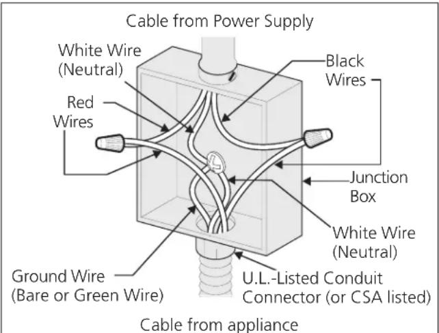
text_image
Cable from Power Supply White Wire (Neutral) Red Wires Black Wires Junction Box White Wire (Neutral) Ground Wire (Bare or Green Wire) U.L.-Listed Conduit Connector (or CSA listed) Cable from applianceFigure 2 3-WIRE GROUNDED JUNCTION BOX
WARNING Improper connection of aluminum house wiring to copper leads can result in a short circuit or fire. Use only connectors designed for joining copper to aluminum, and follow the manufacturer's recommended procedure closely.
WARNING You may not ground the oven through the neutral (white) wire if oven is used in a new branch circuit installation (1996 NEC), mobile home, recreational vehicle, or where local codes do not permit grounding through the neutral (white) wire. When grounding through the neutral (white) wire is prohibited, you must use a 4-wire power supply cable. See Figure 3. Failure to heed this warning may result in electrocution or other serious personal injury.
MICROWAVE/ WALL OVEN COMBINATION INSTALLATION INSTRUCTIONS
If oven is used in a new branch circuit installation (1996 NEC), mobile home, recreational vehicle, or where local codes DO NOT permit grounding through the neutral (white) wire (see figure 3):
- Disconnect the power supply.
- Separate the green (or bare copper) and white appliance cable wires.
- In the circuit breaker, fuse box or junction box: connect appliance and power supply cable wires as shown in Figure 3.
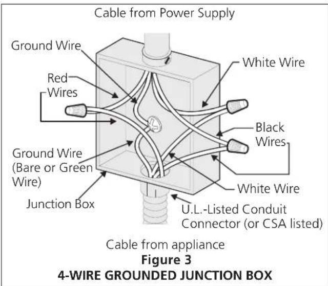
text_image
Cable from Power Supply Ground Wire Red Wires Ground Wire (Bare or Green Wire) Junction Box White Wire Black Wires White Wire U.L.-Listed Conduit Connector (or CSA listed) Cable from appliance Figure 3 4-WIRE GROUNDED JUNCTION BOXDO NOT ground to a gas supply pipe. DO NOT connect to electrical power supply until appliance is permanently grounded. Connect the ground wire before turning on the power (Figure 3).
! CAUTION If connecting to a 4-wire electrical system (mobile homes), the appliance frame MUST NOT be connected to the neutral wire of the 4-wire electrical system.
NOTE TO ELECTRICIAN: The armored cable leads supplied with the appliance are UL-recognized for connection to larger gauge household wiring. The insulation of the leads is rated at temperatures much higher than temperature rating of household wiring. The current carrying capacity of the conductor is governed by the temperature rating of the insulation around the wire, rather than the wire gauge alone.
WARNING
Heavy Weight Hazard
- Use 2 or more people to move and install this combination oven.
- Failure to follow this instruction can result in injury or damage to the unit.
4. Cabinet Installation
WARNING The combination oven can tip when the door is open. The mounting brackets supplied with the oven must be attached to the cabinet and the appliance to prevent tipping of the wall oven and injury to persons.
Mounting Brackets Installation Instructions
- Unpack the wall oven. Remove the bottom trim taped on the oven side panel. Find the 2 mounting brackets and screws included in the literature package.
- Install the mounting bracket in the wall cabinet as shown in Figure 4. Note: To prevent damage to cabinet, it is recommended to drill 1/16" (0.16 cm) dia. pilot holes before installing the mounting brackets.
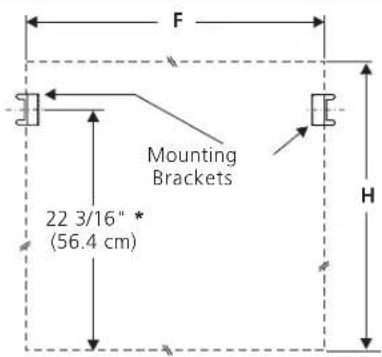
text_image
F Mounting Brackets 22 3/16" * (56.4 cm) H* If wood spacers are needed (see figure1) please calculate this dimension from the top of the spacer to the middle of the mounting bracket.
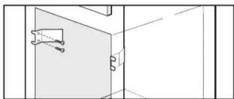
natural_image
Pure architectural line drawing of a room corner with window and door (no text or symbols)Figure 4
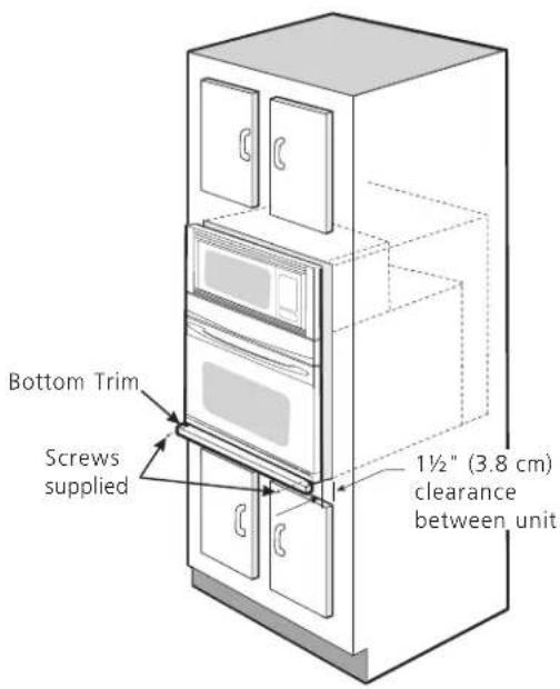
- Insert the oven into the cabinet opening. Slide oven inward leaving 1½" (3.8 cm) clearance between the oven and front of cabinet (see Figure 5). Pull the armored cable through the hole for it in the cabinet and toward the junction box while moving the appliance inward.
MICROWAVE/ WALL OVEN COMBINATION INSTALLATION INSTRUCTIONS
IMPORTANT
Do not lift the oven by the door handle.
- Push the oven in and against the cabinet; the oven side bracket will clip into the mounting bracket installed into the side of cabinet.
To pull out the oven for servicing you must use the two tools supplied with the oven. Insert one tool into hole in each side of oven frame. Holes are visible when door is opened. After inserting tools pull the oven towards you (see Figure 6).
5. Bottom Trim Installation:
Place the top of the bottom trim over the side trim tabs on each side of the oven below the oven door and fix it using the 2 screws supplied in the mounting holes located on each side trim below the oven frame.
text_image
Bottom Trim Screws supplied 1½" (3.8 cm) clearance between unitFigure 5

text_image
Mounting bracket installed in cabinet Oven side trim Cabinet Oven Right Side Tool supplied Mounting bracket released Oven removed from the cabinet Hole where to insert the toolFigure 6
MICROWAVE/ WALL OVEN COMBINATION INSTALLATION INSTRUCTIONS
6. Leveling the Wall Oven
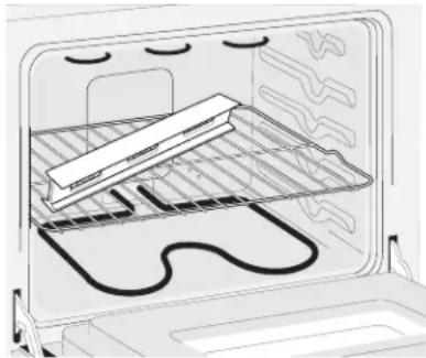
- Install an oven rack in the center of the upper oven (see Figure 7).
- Place a level on the rack. Take 2 readings with the level placed diagonally in one direction and then the other. Use wood shims under the wall oven to level if necessary.
- Repeat in the lower oven if you have a double cavity wall oven. If the level indicates that the rack is not level, use wood shims to reach a compromise for both ovens.
natural_image
Diagram of an oven with a rack and stove, showing internal components (no text or symbols)Figure 7
IMPORTANT NOTE
A cooling fan inside the upper rear part above the oven (some models) provides cooling of the oven electrical and electronic components. If the oven has been operating at high temperatures, the fan will continue to run after the oven is turned off.
7. Checking Operation
Your model is equipped with an Electronic Oven Control. Each of the functions has been factory checked before shipping. However, it is suggested that you verify the operation of the electronic oven controls once more. Refer to the Use and Care Guide for operation.
- Remove all items from the inside of the oven.
- Turn on the power to the oven (Refer to your Use & Care Guide.)
- Verify the operation of the electronic oven controls: Bake - Verify that this function makes the oven hot. 20 seconds after turning oven on, open the door and you should feel heat coming from the oven.
Broil - When the oven is set to BROIL, the upper element in the oven should become red.
Model and Serial Number Location
The serial plate is located along the interior side trim of the oven and visible when the door is opened.
When ordering parts for or making inquires about your oven, always be sure to include the model and serial numbers and a lot number or letter from the serial plate on your oven.
Before You Call for Service
Read the Before You Call for Service Checklist and operating instructions in your Use and Care Guide. It may save you time and expense. The list includes common occurrences that are not the result of defective workmanship or materials in this appliance.
Refer to your Use and Care Guide for service phone numbers.
natural_image
Pure architectural line drawing of a room corner with window and door (no text or symbols)Figura 4
natural_image
Interior view of an oven with a rack and insulation material inside (no text or symbols visible)Figura 7