
AC-DACWT-026 - Unspecified Mach Power - Free user manual and instructions
Find the device manual for free AC-DACWT-026 Mach Power in PDF.

| Product Type | AI Face Recognition Device (with optional temperature detection) |
| Display | IPS full-view HD display (size varies by type; up to 10.1 inches) |
| Camera | Dual 2MP wide-angle wide dynamic cameras |
| Face Database Capacity | Up to 30,000 faces |
| Recognition Speed | < 200 ms |
| Recognition Accuracy | > 99.5% |
| Liveness Detection | Binocular live detection (photo and video anti-counterfeiting) |
| Mask Detection | Yes (with voice prompt) |
| Temperature Measurement | Optional (forehead or wrist); error range ±0.3°C |
| Temperature Measurement Distance | Within 1.2 meters |
| Face Recognition Distance | 1.2 - 2.0 meters |
| Power Supply | DC 12V |
| Operating Temperature | 10°C to 50°C |
| Connectivity | RJ45 Ethernet, Wiegand, RS485, alarm output, USB 2.0 (some types), WiFi/4G (optional) |
| Audio Compression | G.711u / G.711a |
| Installation Methods | Gate, desktop, wall, floor pole bracket |
| Management Software | Smart device platform (SDP2000) and web interface |
| Cloud Service | Supported (remote management via app) |
| Storage | TF card slot (some types) |
| Language Support | Multiple (English, Italian, Spanish, Russian, Arabic, Polish, Japanese, French, Turkish) |
Frequently Asked Questions - AC-DACWT-026 Mach Power
User questions about AC-DACWT-026 Mach Power
0 question about this device. Answer the ones you know or ask your own.
Ask a new question about this device
Download the instructions for your Unspecified in PDF format for free! Find your manual AC-DACWT-026 - Mach Power and take your electronic device back in hand. On this page are published all the documents necessary for the use of your device. AC-DACWT-026 by Mach Power.
USER MANUAL AC-DACWT-026 Mach Power
AI Face Recognition Device
User Manual

natural_image
Illustration of a modern office building with a smartphone on top and a digital display showing a person walking, set against a black-and-white geometric background (no text or symbols)Contents
Chapter 1 Functions and Features....1
1.1 Product Manual....1
1.2 Product Features....1
Chapter 2 Device Introduction....2
2.1 Device Introduction.... 2
2.1.1 Smart Face Recognition Device (Type A Without Temperature Detection)....2
2.1.2 Smart Face Recognition Device (Type B Forehead Temperature Detection)....2
2.1.3 Smart Face Recognition Device (Type C Wrist Temperature Detection)....3
2.1.4 Smart Face Recognition Device (Type D Forehead Temperature Detection)....3
2.1.5 Smart Face Recognition Device (Type E Without Temperature Detection)....4
2.1.6 Smart Face Recognition Device (Type F Forehead Temperature Detection)....5
2.1.7 Smart Face Recognition Device (Type G Without Temperature Detection)....5
2.2 Device Size 6
2.2.1 Smart Face Recognition Device (Type..A)....6
2.2.2 Smart Face Recognition Device (Type..B)....7
2.2.3 Smart Face Recognition Device (Type-C)......8
2.2.4 Smart Face Recognition Device (Type D.&E)....9
2.2.5 Smart Face Recognition Device (Type..F)....10
2.2.6 Smart Face Recognition Device (Type..G).... 11
2.3 Connector Introduction.... 12
2.3.1 Wire connector (Type .A)....12
2.3.2 Wire connector (Type .B)....13
2.3.3 Wire connector (Type .C)....14
2.3.4 Wire connector (Type D &..E).... 15
2.3.5 Wire connector (Type F &..G).... 16
Chapter 3 Installation....18
3.1 Installation of Type A, Type B, and Type C Equipment....18
3.1.1 Installed on the gate....18
3.1.2 Install on the desktop.... 18
3.1.3 Install on floor pole bracket 20
3.1.4 Wall mounted.... 22
3.2 Type D & E equipment installation....23
3.2.1 Install on the desktop 23
3.2.2 Wall Mounted 25
Chapter 4 Smart device platform....27
4.1 Platform Installation.... 27
4.1.1 Configure the computer.... 27
4.1.2 Software Installation....28
4.2 Server introduction....31
4.2.1 Restart the system software....32
4.2.2 Language switch....32
4.3 Introduction of SDP2000 sever control panel....33
Chapter 5 Smart Device Platform Operation....34
5.1 Smart device platform login....34
5.2 Smart Device Platform Introduction 35
5.3 Data Center....36
5.4 Resource....37
5.4.1 Device....37
5.5 Personnel 50
5.5.1 Department....50
5.5.2 Personnel 54
5.6 Visitor....62
5.6.1 Visitor Information....62
5.7 Report....64
5.7.1 Personnel Access....64
5.7.2 Abnormal Access....65
5.7.3 Visitor....66
5.8 System....67
5.8.1 Area....67
5.8.2 User....70
5.8.3 Role....73
5.8.4 Log....76
5.8.5 Cloud Service....77
5.8.6 System Settings....78
5.9 Attendance....79
5.9.1 Attendance Point....79
5.9.2 Attendance Program....82
5.9.3 Check-In Record....86
5.9.4 Attendance Record.... 87
5.10 Terminal version....88
5.10.1 Firmware....88
5.11 Platform Account....90
5.11.1 Modify Password 90
5.11.2 Exit the platform....91
5.11.3 View version....92
Chapter 6 WEB Operation....94
6.1 Internet connection....94
6.2 Browser Login....94
6.3 Picture....95
6.4 Configuration....97
6.4.1 System....97
6.4.2 Local network....105
6.4.3 Face recognition....109
6.4.4 Temperature.... 111
6.4.5 Personnel Inquiry....111
Chapter 7 WEB Operation (Type F...&G)....113
7.1 Internet connection.... 113
7.2 Browser Login.... 113
7.3 My Device....114
7.4 Record....115
7.4.1 Pass Record.... 115
7.4.2 Temperature Measurement Record.... 116
7.5 System Configuration....117
7.5.1 System....117
7.5.2 Network Configuration....122
7.5.3 User Rights....126
7.5.4 Equipment Maintenance.... 129
7.6 Staff....130
7.6.1 Personnel Inquiry....130
7.7 Advance....131
7.7.1 Verification Mode....131
7.7.2 Face Recognition....132
7.7.3 Temperature-taking Setting....133
7.7.4 Interface Configuration....134
7.8 Logout....136
Chapter 8 Appendix....137
8.1 Common problem introduction....137
About this Manual
Without the written permission of the company, any company or individual should not extract, duplicate part of or all of contents of this manual and no spreading in any form. Unless otherwise stipulated, the manual is used as a NOTE. All statements, information and suggestions of the manual do not constitute any ostensive or implied guarantee. Photographs, graphics, charts, and illustrations provided in the manual are for explanation and illustration purposes only, and may differ from specific products. Please prevail in kind.
As the upgrade of the products or other reason, the contents of manual will be upgraded periodically. If you need the latest version of the manual, please scan the QR code below.

Disclaimer
- To the maximum extent permitted by applicable law, the product described, with its hardware, software and firmware, is provided "as is", with all faults and errors, and our company makes no warranties, express or implied, including without limitation, merchantability, satisfactory quality, fitness for particular purpose, and non-infringement of third party, nor is it liable for any special, incidental, incidental, or indirect damages resulting from the use of this manual or the use of our product including but not limited to damages resulting from loss of business profits, loss of data or documentation.
- Regarding to the product with internet access, the use of product shall be wholly at your own risks. Our company shall not take any responsibilities for abnormal operation, privacy leakage or other damages resulting from cyber attack hacker attack, virus inspection, or other internet security risks; however, our company will provide timely technical support if required.
● Surveillance laws vary by jurisdiction. Please check all relevant laws in your jurisdiction before using this product in order to ensure that your use conforms the
applicable law. Our company shall not be liable in the event that this product is used with illegitimate purposes.
- In the event of any conflicts between this manual and the applicable law, the legal provisions shall prevail.
Data Security Statement
- In the process of using the product, you will collect, store and use personal data. In the process of product development, our company implements the principles of personal data protection. For example, if you use a face recognition device, the biometric data will be encrypted and stored on your device.
- As a data controller, when collecting, storing and using personal data, you must comply with applicable laws and regulations concerning the protection of personal data, including but not limited to taking protective measures on personal data. We strongly recommend that you perform reasonable rights management on the device, strengthen the physical security of device application scenarios, and conduct regular security assessments.
Safety Precautions

WARNING
- Electrical safety regulations of the nation and the region must be strictly followed during installation or use.
- Do not connect multiple device with one single power adapter (Overload for adapter may lead to over-heat or fire hazard).
- The product must use the recommended wire assembly (power cord) and use it within its rated specifications.
- Shut down the power while connecting or dismounting the device. Do not operate with power on.
- Shut down the power and unplug the power cable immediately when there is smoke, odor or noise rising from the device. Then contact the dealer or service center.
- Please contact the local dealer or latest service center when IPC works abnormally. Do not attempt to disassemble or modify the device yourself. (We shall shoulder no responsibility for problems caused by unauthorized repair or maintenance).

CAUTION
- Please do not install the device in direct sunlight or around heat sources.
- Do not install the device in a humid, dusty or smoky place.
- Please keep the device installed in a stable place, taking care to avoid the product falling or being hit by falling objects.
- Please install the device in a well-ventilated place.
- Do not aim the lens of the device at objects with strong light, such as the sun, incandescent lamp, etc., otherwise the lens may be damaged.
- Please use a very soft dry cloth or other alternatives to wipe the surface, do not use alkaline cleaners, and avoid scratching the device with hard objects.
- Please understand that you are responsible for properly configuring all passwords and other product-related security settings, and keeping your user name and password properly.
- Biometric products cannot be 100% suitable for any anti-counterfeiting environment. For high security level places, please use the combined authentication method.

NOTE
● After receiving the product, please open the box, take out the equipment, and count the products and accessories according to the packing list.
- If you find that the contents of the box are damaged or any accessories are missing, please contact the dealer in time.
Chapter 1 Functions and Features
1.1 Product Manual
The AI Face Recognition Device is a face recognition temperature-sensing terminal independently developed by our company. It adopts a number of high-tech, such as video codec technology, audio codec technology, embedded system technology, storage technology, network technology and intelligent technology, etc. Excellent face recognition and living body judgment function.
Moreover, the body temperature detection technology based on the AI algorithm for accurate correction can match the face and body temperature in real time, and the device will broadcast a voice prompt when the body temperature is abnormal.
After the smart device installation is complete, after access the network, you can manage the device through the smart device platform or the device web page.
In order to meet the multi-element needs of various applications, this product can be widely used in airports, exit and entry points, railway stations, government agencies, schools, scenic spots, large factories and other places that need to be identified. It can help customers to carry out efficient, safe and intelligent entrance and exit management.
1.2 Product Features
- Using IPS full-view high-definition display, the image without smear and no delay.
- Using two 2 million high-definition wide-angle wide dynamic cameras, support binocular live detection (photo and video anti-counterfeiting).
- A photosensitive sensor is used to automatically adjust the fill light intensity through white light and infrared light. Support smart fill light.
- Use Linux system, low power consumption, high stability.
- Adopt deep learning algorithm, support 30,000 face database.
- Adopt G.711u and G711a audio compression formats.
● Recognition speed <200ms, Accuracy >99.5%.
● Mask detection to determine whether the identified person is wearing a mask.
● Support staff are identified when wearing a mask.
● Temperature error range+/-0.3°C.
- Background management, abnormal records, device management, personnel management.
- Support data upload to the network, can upload the device comparison results and captured photos to the platform for real-time storage, and support to upload files after network recovery after disconnection.
- App remote management, message push.
- Face recognition distance is 1.2-2.0M, it is recommended to paste a mark on the floor mark distance.
● Temperature measurement distance: within 1.2 meters, it is recommended to paste a mark on the floor mark distance.
● Operating temperature: 10^ C- 50^ C.
Chapter 2 Device Introduction
2.1 Device Introduction
2.1.1 Smart Face Recognition Device (Type A Without Temperature Detection)
The front panel, rear panel of Smart Face Recognition Device as shown in Figure 2-1 below.

Figure 2-1
2.1.2 Smart Face Recognition Device (Type B Forehead Temperature Detection)
The front panel, rear panel of Smart Face Recognition Device as shown in Figure 2-2 below

Figure 2-2
2.1.3 Smart Face Recognition Device (Type C Wrist Temperature Detection)
The front panel, rear panel of Smart Face Recognition Device as shown in Figure 2-3 below.
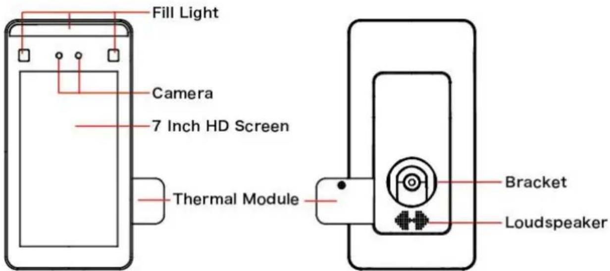
Figure 2-3
2.1.4 Smart Face Recognition Device (Type D Forehead Temperature Detection)
The front panel, rear panel of Smart Face Recognition Device as shown in Figure 2-4 below.
Front

Figure 2-4 ①
Back

Figure 2-4 ②
2.1.5 Smart Face Recognition Device (Type E Without Temperature Detection)
The front panel, rear panel of Smart Face Recognition Device as shown in Figure 2-5 below.
Front

Figure 2-5 ①
Back

Figure 2-5 ②
2.1.6 Smart Face Recognition Device (Type F Forehead Temperature Detection)
The front panel, rear panel of Smart Face Recognition Device as shown in Figure 2-1 below.


Figure 2-6
① Fill Light ② 1080P Camera
③ 10.1 Inch HD Screen ④ Card
⑤ Antenna ⑥ Card slot (SIM card & TF card)
⑦ Bracket and Outlet ⑧ Speaker
2.1.7 Smart Face Recognition Device (Type G Without Temperature Detection)
The front panel, rear panel of Smart Face Recognition Device as shown in Figure 2-1 below.


Figure 2-7
① Fill Light ② 1080P Camera
③ 10.1 Inch HD Screen ④ Card
⑤ Antenna ⑥ Card slot (SIM card & TF card)
⑦ Bracket and Outlet ⑧ Speaker

NOTE
- The schematic diagram of the panel does not represent the actual size and proportion of the product, please refer to the actual product for details.
2.2 Device Size
2.2.1 Smart Face Recognition Device (Type A)
The size of Smart Face Recognition Device as shown in Figure 2-8 below.

Figure 2-8
2.2.2 Smart Face Recognition Device (Type B)
The size of Smart Face Recognition Device as shown in Figure 2-9 below.

Figure 2-9
2.2.3 Smart Face Recognition Device (Type C)
The size of Smart Face Recognition Device as shown in Figure 2-10 below.

Figure 2-10
2.2.4 Smart Face Recognition Device (Type D & E)
The size of Smart Face Recognition Device as shown in Figure 2-11 below.

Figure 2-11
2.2.5 Smart Face Recognition Device (Type F)
The size of Smart Face Recognition Device as shown in Figure 2-12 below.

Figure 2-12
2.2.6 Smart Face Recognition Device (Type G)
The size of Smart Face Recognition Device as shown in Figure 2-13 below.

Figure 2-13
2.3 Connector Introduction
2.3.1 Wire connector (Type A)
The wire connectors for Smart Face Recognition Device are shown in Figure 2-14 below.

Figure 2-14
① RESET (Long press to restore factory settings.)
② DC12V Power Interface
③ RS485
④ RJ45 Network Interface
⑤ 1. Alarm out-, 2. Alarm out+
⑥ 1.NO, 2.COM, 3.NC
⑦ 1. GND, 2. D1, 3. D0
2.3.2 Wire connector (Type B)
The wire connectors for Smart Face Recognition Device are shown in Figure 2-15 below.

Figure 2-15
① RESET (Long press to restore factory settings.)
② DC12V Power Interface
③ RS485
④ RJ45 Network Interface
⑤ 1. Alarm out-, 2. Alarm out+
⑥ 1.NO, 2.COM, 3.NC
⑦ 1.GND, 2.D1, 3.D0
2.3.3 Wire connector (Type C)
The wire connectors for Smart Face Recognition Device are shown in Figure 2-16 below.

Figure 2-16
① RESET (Long press to restore factory settings.)
② DC12V Power Interface
③ RS485
④ RJ45 Network Interface
⑤ 1. Alarm out-, 2. Alarm out+
⑥ 1.NO, 2.COM, 3.NC
⑦ 1.GND, 2.D1, 3.D0
2.3.4 Wire connector (Type D & E)
The wire connectors for Smart Face Recognition Device are shown in Figure 2-17 below.

flowchart
graph TD
    A["DC12V"] --> B["RS485A"]
    A --> C["RS485B"]
    A --> D["NC"]
    A --> E["COM"]
    A --> F["NO"]
    A --> G["GND"]
    A --> H["D0"]
    A --> I["D1"]
    A --> J["GND"]
    B --> K["1.D0"]
    B --> L["2.D1"]
    B --> M["3.GND"]
    C --> N["RS485"]
    C --> O["1.NC"]
    C --> P["2.COM"]
    C --> Q["3.NO"]
    D --> R["1. NC"]
    D --> S["2.COM"]
    D --> T["3.NO"]
    E --> U["DC12V"]
Figure 2-17
The specific wiring ports are shown in Table 2-1:
| Interface | Mark | Wiring Color |
| Wiegand Interface | D0 | Blue |
| D1 | Purple | |
| W_GND | Gray | |
| RS485 Interface | 485A | Brown |
| 485B | Orange | |
| Relay Interface | NC | Green |
| COM | Yellow | |
| NO | White | |
| Power Interface | GND | Black |
| DC12V | Red |
Table 2-1
2.3.5 Wire connector (Type F & G)
The wire connectors for Smart Face Recognition Device are shown in Figure 2-18 below.

Figure 2-18
① RESET (Long press to restore factory settings)
② USB2.0 interface, connect to mouse or USB
③ Access control interface (1.NO, 2.NC, 3.COM)
④ Wiegand interface (1.D0, 2.D1, 3.GND)
⑤ 1. Alarm out+, 2. Alarm out-
⑥ RJ45 network port, access to Ethernet
⑦ 1.RS485+, 2.RS485-
⑧ DC12V Power Interface
Chapter 3 Installation
Installation Environment:
● The device should be at least 2 meters away from the light source and at least 3 meters away from the window and door to avoid direct sunlight.
● To make the device work better, avoid installing multiple devices face to face.
3.1 Installation of Type A, Type B, and Type C Equipment 3.1.1 Installed on the gate
Step 1: Open a hole with a diameter of D = 35mm on the gate, and the recommended position is 1/3 to 1/4 from the entrance end.
Step 2: Insert the equipment mounting bracket and the connecting wire into the opening of the gate. The connecting wire passes through the gasket and nut and fixes the lock nu Step 3: Adjust the device to a suitable angle (angle between 5° -15° vertical).

3.1.2 Install on the desktop
Step 1: With the base of the table bracket facing up, remove the screws and the cover.

Step 2: Pass the wire of the device through the holes, spacers, and nuts of the bracket, and lock the nut to fix the device on the top of the bracket.

Step 3: Pass the wire of the device through the cover, and fix the cover on the bracket with the locking screw.

3.1.3 Install on floor pole bracket
Step 1: Remove the screw under the floor pole bracket, align the base with the bracket, and fix the base with the locking screw.

Step 2: Remove the 2 screws on the top cover of the floor pole bracket and remove the top cover.

Step 3: Pass the wire of the device through the holes, spacers, and nuts of the top cover of the bracket, and lock the nut to fix the device on the top cover of the bracket.

Step 4: Connect the wire, install the top cover of the bracket to the floor pole bracket, a fix the lock nut.

Step 5: Adjust the device to an appropriate angle (vertical 5^-15^ included angle).
3.1.4 Wall mounted
Step 1: Open holes in the wall according to the installation sticker and install the rubber plug.

natural_image
Pure electrical circuit lines without any symbolsStep 2: Fix the wall mount bracket to the wall with screws.

natural_image
Technical line drawing of a circular mechanical component with multiple bolt holes and two separate cylindrical features (no text or symbols)-Step 3: Install the device on the wall bracket, align the screw holes on the left and right sides, and fix the lock screws.

natural_image
Technical line drawing of a smartphone with a circular component and cable connectors (no text or symbols)
NOTE
- It is recommended that the location of the sticker is 1.4 meters, and users can adjust it according to their height.
3.2 Type D & E equipment installation
3.2.1 Install on the desktop
Step 1: Turn the camera end of the device upward and turn it to the back.
Step 2: Put the silicone ring into the screw hole position on the inside of the desktop bracket.

Step 3: Align the holes of the bracket with the holes of the device, and fasten the bracket to the body with screws.

natural_image
Diagram showing a device on a stand before and after change, with no visible text or symbols.Step 4: Connect wires. To spread the desktop stand and adjust the angle as needed.

natural_image
Technical illustration of a mechanical assembly before and after disassembly, showing internal components and motion direction (no text or symbols)3.2.2 Wall Mounted
Step 1: According to the installation sticker, open holes on the wall and install the rubber plug.

Step 2: Pass the network cable and 10PIN wire through the wall bracket, and arrange the wire into the wire groove, then fix the bracket to the wall with screws.

Step 3: Connect wires, install the device on the wall bracket, then align the screw holes of the left and right sides, install the nuts and lock the screws.

natural_image
Technical diagram showing a mechanical assembly inside a circular housing and its side view with a screen (no text or symbols)Chapter 4 Smart device platform
The intelligent terminal platform is a background management system used for device management, personnel management, visitor management, report management, and data center.
4.1 Platform Installation

NOTE
● Before installation, please make sure that the computer is a Windows 64-bit system.
- When running the platform software with a non-computer administrator account, you must run it as an administrator.
● The device defaults to enable "DHCP" of type A, type B, type C, type D, type E..
If the device is not connected to a DHCP server, but DHCP is set to "On", the default values are as follows:
IP: "192.168.1.88"
Network Mask: "255.255.255.0" Port: "7080"
● Factory default IP of F & G device: "192.168.1.88"
Subnet mask: "255.255.255.0" Port: "80"
4.1.1 Configure the computer
IPv4 address of the PC needs to be in the same network segment with the IP address of the IP camera for normal operation. Specific settings in window system can refer to the following methods:
Step 1: Check the IPv4 address of PC, click "Start"/ "Control Panel"/ "Network and Internet"/ "Network and Sharing Center"/ "Local Network"/ "Details". If you have an IP of 192.168.1.X, you can add the device directly on the platform. If there is no IP address on this network segment, proceed to Step 2 to increase the IP address on this network segment.

Step 2: Click "Close"→ "Properties", double-click "Internet Protocol Version 4 (TCP / IPv4)".

Step 3: Click "Advanced"→ "Add" under the IP address, enter the same network segment IP as the device (such as 192.168.1.165) → "Add"→ "OK"→ "OK"→ "OK", add IP and exit.


NOTE: The IPv4 address can not be conflicted when you add in LAN.
4.1.2 Software Installation
Software installation is shown in Figure 4-1 below.

SDP2000_EN_x64_V2.2.2.exe
Figure 4-1
The specific steps for installing the smart terminal platform are as follows:
Step 1: Double-click the SDP2000 application shown in Figure 1-1 above, and click "Next".

Step 2: Select the destination location, click "Next".

Step 3: Wait for the installation progress to complete. Click "Finish".

Step 4: After the platform is installed, the control panel pops up on the desktop.


NOTE
- Currently, SDP2000_EN_x64_VX.X.X.exe software can only be installed on a computer with 64 bit Windows system.
- After the smart terminal platform is installed, a shortcut icon", pops up on the desktop. Double-click to run the program.
- When installing the software, the anti-virus software in the computer must be closed.
4.2 Server introduction

Right-click the "icon in the lower right corner of the desktop, you can restart the software and switch the system language and other operations, as shown in Figure 4-2 below.

Figure 4-2
4.2.1 Restart the system software
When abnormality occurs on the smart terminal platform, such as abnormal reading or abnormal data interface request, please follow the steps below:

Step 1: Right-click the "icon" in the lower right corner of the desktop.
Step 2: Check if the status of Nginx, Mysqld, and SDP2000 is" "green (normal status), if any item displays" "gray status, then you need to "restart" the software, so that the status of PHP, Nginx, and MariaDb becomes" "green (Normal state), as shown in Figure 4-3 below.

Figure 4-3

NOTE
- When the status of Nginx, Mysqld and SDP2000 are all" "gray, click "open all", restart all, wait for the status to change to" ".
4.2.2 Language switch
The steps to switch the language of the web page and server are as follows:

Step 1: Right-click the "icon" in the lower right corner of the desktop.
Step 2: Click "Language", select language to switch, click "OK".

Step 3: Right-click the "icon in the lower right corner of the desktop, click "Quit".

Step 4: Double-click the desktop icon" " to restart the smart terminal platform
4.3 Introduction of SDP2000 sever control panel
The interface of SDP2000 server control panel is shown in Figure 4-4 below.

Figure 4-4
The functions of SDP2000 server control panel are shown in Table 4-1 as below.
| Button | NOTE |
| Start | Start all services |
| Stop | Stop all services |
| Close | Close the taskbar |
 | Enter the SDP2000 login interface |
Table 4-1
Chapter 5 Smart Device Platform Operation
5.1 Smart device platform login
The steps to log in to SDP2000 are as follows

Step 1: Double-click the desktop icon " " to run the smart device platform.

Step 2: Double-click the desktop icon "pop up SDP2000 server control panel, as shown in Figure 5-1 below.

Figure 5-1
Step 3: In SDP2000 server control panel click " 🔊" to enter the login interface, as shown in Figure 5-2 below.

Figure 5-2
Enter the user name and password, the default user name is admin, the password is admin, click "Login".

NOTE
- It is recommended to set Google Chrome or Firefox as the computer's default browser.
5.2 Smart Device Platform Introduction
Enter to smart device platform control interface, it is composed of Data Center, Resource, Personnel, Visitor, Report, System and Terminal Version, as shown in Figure 5-3 below.

pie
| Statistic | Value | | --------------------- | ----- | | Off line | 0 | | On line | 0 | | Total person | 0 | | Issued | 0 | | Inf visited | 0 | | Today | 0 | | Captained | 0 | | Historical visits | 0 | | No visit | 0 |Figure 5-3
The functions of Smart device platform control interface are shown in Table 5-1 as below.
| Menu | Functions | |
| Data Center | Data Center | Used to display statistical equipment, personnel, visitors, snapshot data and trend distribution. |
| Resource | Device | Used to add devices, view, configure, delete, an upgrade devices. |
| Personnel | Department | For adding, viewing, editing, and deleting organizations. |
| Personnel | Add, view, edit and delete people to an existin organization. | |
| Visitor | Visitor Information | Used to register, view and delete visitor record visitor information. |
| Report | Personnel Access | Used to view and export all normal access rec including internal personnel records and visitor records. |
| Abnormal Access | Used to view and export all abnormal entry an exit records, such as "not wearing a mask", "stranger", "abnormal body temperature" and other records. | |
| Visitor | Used to view and export all guest records that been visited. | |
| Attendance | Attendance Point | Used to set attendance locations, where you ca add or delete attendance locations. |
| Attendance Program | Used to set the attendance plan, here you can or delete the attendance plan. | |
| Check-In Record | Used to view check-in records. | |
| Attendance Record | Used to view attendance records. | |
| System | Area | It can be divided into multiple areas according the actual needs of users, where areas can be added, deleted, edited. |
| User | Used to view, add, edit, delete the account of smart device platform . | |
| Role | User roles with different permissions can be configured according to actual needs, and roles be added, edited, and deleted. | |
| Log | Used to view and export all platform logs. | |
| Cloud Services | Used to activate cloud services. | |
| System Settings | Used to set the system language. | |
| Terminal Version | Firmware | Used to store and delete the firmware version the device. |
Table 5-1
5.3 Data Center
The SDP2000 platform data center provides users with comprehensive data services, and displays the equipment, personnel, visitors, and snapshot data managed by the platform in the form of data charts, allowing you to quickly grasp the latest developments in equipment and personnel. At the same time, you can enter the time to view visitor trends and abnormal trends, as shown in Figure 5-4 below:

donut
| Category | Value | | ---------- | ----- | | Off line 0 | 0 | | On line 0 | 0 |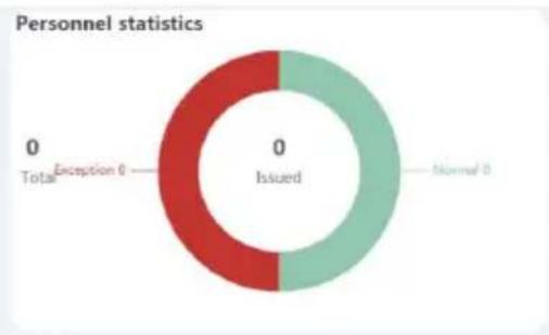
donut
| Category | Value | | ------------ | ----- | | Total | 0 | | Exception 0 | 0 | | Normal | 0 | | Issued | 0 |
pie
Visitor statistics | Visitor | Count | | :--- | :--- | | Had visited D | 15 | | No visit D | 25 | | Historical visits | 0 | | (Total) | 0 |
line
| Date | visitor trends | Abnormal trend | | ---------- | --------------- | -------------- | | 2020-07-27 | 2020-08-02 | 2020-07-27 | | 2020-08-02 | 2020-08-02 | 2020-08-02 |
pie
| Category | Value | | ---------------- | ----- | | Exception 0 | 0 | | Normal 0 | 0 | | I temperature 0 | 0 | | Stronger 0 | 0 | | No mask 0 | 0 |Figure 5-4
5.4 Resource
5.4.1 Device
Device management can add, delete, configure devices, and export device lists.
5.4.1.1 Add device
■ Add device by LAN search

NOTE
● Make sure that the device to be added is on the same local area network as the computer, and it is turned on and online.
- The status of the device to be added by the platform must be "Not Added".
The specific steps are as follows:
Step1: In the smart device platform interface, click "Resource→Device" to enter the device management interface, as shown in Figure 5-5 below.

Figure 5-5
Step 2: Click "Search Device", click the " ” icon of the device to be added, as shown in Figure 5-6 below.

Figure 5-6
Step 3: Configure device network parameters(IP Address, Network Mask, Gateway, DNS), click "Submit", as shown in Figure 5-7 below.

Figure 5-7
Step 4: Click "⊕", select the region to which the device belongs, click "Set", as shown in Figure 5-8 below.

Number of selected devices: 1 Select the device binding region (default is the first region)

Figure 5-8
Step 5: The device is successfully added to the device list, as shown in Figure 5-9 below.

Figure 5-9
■ Add device manually

NOTE
- Make sure that the device to be added is on the same local area network as the computer, and it is turned on and online. The network is not connected to a DHCP server.
- The status of the device to be added by the platform must be "Not Added".
- When the device is not connected to the DHCP server, the default IP is "192.168.1.88", the password is "12345", and the port is "7080".
The specific steps are as follows:
Step 1: In the smart device platform interface, click "Resource→Device" to enter the device management interface, as shown in Figure 5-10 below.

Figure 5-10
Step 2: Click "☐", enter the network information of the device to be added(IP Address, Device Password, Port, Area ), select area, click "Save", as shown in Figure 5-11 below.

Figure 5-11
Step 3: The device is successfully added to the device list, as shown in Figure 5-12 below

Figure 5-12
5.4.1.2 Delete device
The specific steps are as follows:
Step 1: In the smart device platform interface, click "Resource→Device" to enter the device management interface, as shown in Figure 5-13 below.

Figure 5-13
Step 2: Click the" to delete the device →Confirm", as shown in Figure 5-14 below.

Figure 5-14
Step 3: The selected device has been deleted, as shown in Figure 5-15 below.

Figure 5-15

NOTE
- When you want to delete multiple devices at the same time, you can first select the device to be deleted in the device list, click " Del →Confirm" below to complete the deletion.
5.4.1.3 Configure device
The specific steps are as follows:
Step 1: In the smart device platform interface, click "Resource→Device" to enter the device management interface, as shown in Figure 5-16 below.

Figure 5-16
Step 2: Click the device to be configured" "to enter the configuration interface, it is composed of Basic Parameters, Network Config, Remote Config, Version Info and Function Parameters, as shown in Figure 5-17 below.
Conf.


Figure 5-17
Step 3: Configure the device according to actual needs.
√ Basic Parameters Configuration:
- In the Conf. interface, click "Basic Parameters".
2.Input Device Name, Device Password, Area, click "Set".
[Device Name] The default is the device serial number, which can be modified as needed.
[Device Password] The default is 12345, which can be modified as needed.
[Area] Select the area where the device is located according to the actual situation.
√ Network Configuration:
-
In the Conf. interface, click "Network Config".
-
Modify the IP Address, Network Mask, Gateway, DNS1&DNS2 of the device according to actual needs, click "Set", as shown in Figure 5-18 below.

Figure 5-18
[IP Address] The default is 192.168.1.88, which can be modified as needed.
[Network Mask] The default is 255.255.255.0, which can be modified as needed.
[Gateway] The default is 192.168.1.1, which can be modified as needed.
[DNS1] The preferred DNS server.
[DNS2] Alternative DNS server.

NOTE
● The above is the default network parameters when the device is not connected to the DHCP server
√ Remote Configuration:
Remote configuration is used to restart the device, set the device volume, screen brightness and other related parameters.
-
In the Conf. interface, click "Remote Config".
-
Restart, upgrade, switch languages and restore the factory smart device according to actual needs, set the volume, screen brightness and supplementary lighting, as shown in Figure 5-19 below.

Figure 5-19
√ Version Info:
- In the Conf. interface, click "Version Info".
- Here you can view the device model, firmware version and serial number and other information, as shown in Figure 5-20 below.
Conf.

| Basic Parameters | Network Config | Remote Config | Version Info | Function Parameters |
| Device Type | FK03AYW | |||
| Firmware | FK03AYWEN_MX806_V20.3.30.1 | |||
| Serial number | 7101553033514 | |||
Figure 5-20
√ Function Parameters Configuration:
-
In the Conf. interface, click "Function Parameters".
-
Here you can set Temperature Check, Alarm Temperature, Stranger Access and Mask Detection.
- click "Set" to complete function parameter configuration, as shown in Figure 5-21 below.
Conf.


Figure 5-21
[Temperature Check] The default is off. After the device is turned on, the device starts to measure the temperature of passers-by, and the measured temperature is displayed on the device screen.
[Alarm Temperature] The default is 37.3^ C. After enable Temperature Check, when the device detects that the passing person exceeds the alarm temperature, the device will broadcast "Abnormal Temperature" and prohibit the person from passing.
[Stranger Access] The default is off. After enable Stranger Access, when the device detects a stranger, the person is allowed to pass through.
[Check Mask] The default is off. After enable Mask Detection, when the device detects that the passing person is not wearing a mask, the device will broadcast "No Mask".
[Save Photo] The default is off. At this time, all the places that capture pictures (such as personnel pass records, abnormal pass records, historical visitor records) will not capture face pictures. After it is turned on, the system will save a snapshot of the face of the passer-by.
5.4.1.4 Report Export
The specific steps are as follows:
Step 1: In the smart device platform interface, click "Resource→Device" to enter the device management interface, as shown in Figure 5-22 below.

Figure 5-22
Step 2: Click "", choose the format of the exported document, such as "Word", as shown in Figure 5-23 below.
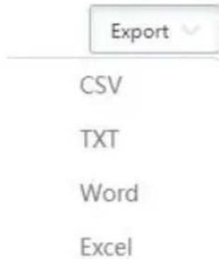
Figure 5-23
Step 3: The device list is exported in word document format, and the document content is shown in Figure 5-24 below.
| Device Name | Device Type | SN | IP Address | Device MAC | Version | Communication Port | Area | State | Engage |
| F3D | FXO205YV | 1231545645864 | 172.18.193.208 | b0:b7:a1:aa:01:91 | FXO20SYVEN_P4_V10_3_22_5 | 7080 | Default area 0n line | ||
Figure 5-24
5.4.1.5 Batch Upgrade Firmware
Batch Upgrade Firmware can simultaneously upgrade the firmware of one or multiple devices of the same model.
The specific steps are as follows:
Step 1: In the smart device platform interface, click "Terminal Version→Firmware" to enter the firmware version interface, as shown in Figure 5-25 below.

Figure 5-25
Step 2: Click +dd" to enter the version records interface, as shown in Figure 5-26 below.

Figure 5-26
Step 3: Input the version name and the version description, click "Select file" to upload the firmware version to the platform
Step 4: Click "Submit".
Step 5: Click "Resource→Device" to enter the device management interface, as shown in Figure 5-27 below.

Figure 5-27
Step 6: Select the device to upgrade, click "", as shown in Figure 5-28 below.

Figure 5-28
Step 7: Select the upgrade firmware version on the platform, click "To upgrade", wait for the device side to upgrade, the device will automatically restart after the upgrade is completed, and the upgrade is successful after the restart, as shown in Figure 5-29 below.
Batch upgrade firmware version - ☐ X
Number of selected devices: 1
Please select

Batch upgrade all the equipment in the table(Don't need to check, filter by search criteria)
Figure 5-29

NOTE
- When the device is being upgraded, please do not power off the device or disconnect the Internet.
5.5 Personnel
5.5.1 Department
Smart device platform can add, edit and delete organization.
5.5.1.1 Add Organization
The specific steps are as follows:
Step 1: In the smart device platform interface, click "Personnel→Department" to enter the organization management interface, as shown in Figure 5-30 below.

Figure 5-30
Step 2: Click Add", as shown in Figure 5-31 below.

Figure 5-31
Step 3: Input the organization information (Department NO., Department Name, Superior Department, Remark), click "Submit" to complete the addition of the organization, as shown in Figure 5-32 below.

Figure 5-32
5.5.1.2 Edit organization
The specific steps are as follows:
Step 1: In the smart device platform interface, click "Personnel→Department" to enter the organization management interface, as shown in Figure 5-33 below.

Figure 5-33
Step 2: Click the "☐" of the organization you want to edit, as shown in Figure 5-34 below.

Figure 5-34
Step 3: Modify the organization information(Department Name, Remarks), click "Submit" to complete the modification.
5.5.1.3 Delete organization
The specific steps are as follows:
Step 1: In the smart device platform interface, click "Personnel→Department" to enter the organization management interface, as shown in Figure 5-35 below.

Figure 5-35
Step 2: Click the "→Confirm" of the organization you want to delete to complete the organization deletion, as shown in Figure 5-36 below.

Figure 5-36

NOTE
- Multiple organizations can be selected at the same time, click "to delete multiple organizations(organizations without personnel) at the same time.
● All organizations can only be edited, not deleted. - No Group organizations cannot be edited or deleted.
5.5.1.4 Organization search
The specific steps are as follows:
Step 1: In the smart device platform interface, click "Personnel→Department" to enter the organization management interface, as shown in Figure 5-37 below.

Figure 5-37
Step 2: Select all, or an organization.
Step 3: Enter a piece of information for the search organization(Such as Department No.,
Department Name or Creation Date), click "", search results will be displayed in the organization list, as shown in Figure 5-38 below.

Figure 5-38

NOTE
● After searching for the organization, click "Export" to export the searched organization-related information to the document
5.5.2 Personnel
The specific steps are as follows:
Step 1: In the smart device platform interface, click "Personnel→Personnel" to enter the personnel management interface, as shown in Figure 5-39 below.

Figure 5-39
Step 2: Choose an organization, click 'Add', as shown in Figure 5-40 below.

Figure 5-40
Step 3: Upload personnel pictures locally, enter personnel information(Personnel NO., Name, Gender, Department, Certificate Type, Certificate NO., Mobile Phone NO.).
Step 4: Click " + Authorize" to set the authorization area, and click "Submit", all devices in this area are authorized to this person, as shown in Figure 5-41 below.

Figure 5-41
Step 5: Click "Submit" to complete the addition of personnel, as shown in Figure 5-42 below.

Figure 5-42
5.5.2.2 Add personnel in batches
The specific steps are as follows:
Step 1: In the smart device platform interface, click "Personnel→Personnel" to enter the personnel management interface, as shown in Figure 5-43 below.

Figure 5-43

Step 2: Choose an organization, cliInput personnel images in batches".
Step 3: According to the actual situation, choose the folder or compressed package to store the personnel pictures, click "Confirm", as shown in Figure 5-44 below.
Staff photo import

Picture naming formats can be divided into three formats:
1、Name.jpg
2. Name_Department Name.jpg
3. Name_Department Name_Personnel No.jpg (tip:Department name must exist in the system, and personnel number must be unique)

Please use zip to upload more than 500 pictures.

The file size cannot exceed 80m
Upload Zip
Upload file
Number of selected files:7
Cancel
Confirm
Figure 5-44

NOTE
- The uploaded person photos can only be uploaded successfully if they are in JPG format.
● The clearer the uploaded pictures, the more accurate the device identification and the faster the speed, but the uploaded folder cannot exceed 80M, and if it is greater than 1500 pictures, please use the zip compression package to upload.
● The picture should be named as follow:
1) Name.jpg
2) Name_Department Name.jpg
3) Name_Department Name_Personnel No..jpg
Step 4: Wait for the upload progress to be completed, the personnel picture is uploaded, as shown in Figure 5-45 below.

Figure 5-45
Step 5: Click "Input personnel in batches→ batch add people templates", enter the information of the person corresponding to the imported picture into the template, and the corresponding number.
Step 6: Click "Import" to complete the information of the person who has imported the picture.
The specific steps are as follows:
Step 1: In the smart device platform interface, click "Personnel→Personnel" to enter the personnel management interface, as shown in Figure 5-46 below.

Figure 5-46
Step 2: Choose an organization, click the " " of the person to be edited, enter the relevant information of the person, click "Submit" to complete personnel editing, as shown in Figure 5-47 below.

Figure 5-47
5.5.2.4 Delete Personnel
The specific steps are as follows:
Step 1: In the smart device platform interface, click "Personnel→Personnel" to enter the personnel management interface, as shown in Figure 5-48 below.

Figure 5-48
Step 2: Choose an organization, click the icon of the person to be edited "→Confirm" to complete personnel deletion.
5.5.2.5 Authorize / Reissue
Personnel issued refers to the distribution of personnel information to smart devices. The specific steps are as follows:
Step 1: In the smart device platform interface, click "Personnel→Personnel" to enter the personnel management interface, as shown in Figure 5-49 below.

Figure 5-49
Step 2: Select the authorized person, click "Authorize/Reissue" of the person to be issued, select the authorized area, and click "Submit", as shown in Figure 5-50.

Figure 5-50

NOTE
● After adding people pictures in batches, send the pictures to the device according to the actual situation.
5.5.2.6 Search Personnel
The specific steps are as follows:
Step 1: In the smart device platform interface, click "Personnel→Personnel" to enter the personnel management interface, as shown in Figure 5-51 below.

5-51
Step 2: Select "All", or an organization.
Step 3: At the top of the interface, enter a piece of information (such as NO., Name, Mobile Phone NO., Certificate NO., or state) of the search person, click "", search results will be displayed in the people list, as shown in Figure 5-52 below.

Figure 5-52

NOTE
● After searching for personnel, click "Export" to export the relevant information of the searched personnel to the document.
5.6 Visitor
5.6.1 Visitor Information
5.6.1.1 Visitor Registration
The specific steps are as follows:
Step 1: In the smart device platform interface, click "Visitor→Visitor Information" to enter the visitor information interface, as shown in Figure 5-53 below.

Figure 5-53
Step 2: Click "Visitor Registration" to enter the visitor registration interface, as shown in Figure 5-54 below.

Figure 5-54
Step 3: Upload visitor pictures, register visitor information, click "Submit" to complete visitor registration, as shown in Figure 5-55 below.

Figure 5-55

NOTE
- When registering visitor information, Gender, Certificate Type, Visiting Unit, Personnel Visited and Department Visited are optional items, other items with "*" are required items.
5.6.1.2 View visitor records
The specific steps are as follows:
Step 1: In the smart device platform interface, click "Visitor→Visitor Information" to enter the visitor information interface, as shown in Figure 5-56 below.

Figure 5-56
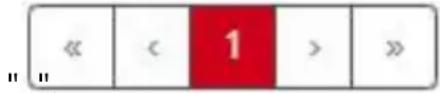
Step 2: To view all visitor information, you can turn pages by

NOTE
- At the top of the interface, enter a piece of information (such as Visitor Name, Gender, Certificate NO., Mobile Phone NO., State, Accessible Area, or Source) of a visitor information, click "", search results will be displayed in the visitor list.
5.7 Report
5.7.1 Personnel Access
Personnel access records are used to view and export all normal access records, including internal personnel records and visitor records.
5.7.1.1 View Personnel Access
The specific steps are as follows:
Step 1: In the smart device platform interface, click "Report→Personnel Access" to enter the personnel access interface, as shown in Figure 5-57 below.

Figure 5-57
Step 2: To view all the passerby records in the personnel access record list (displayed in

order from now to the past), you can turn the page by"".

NOTE
- At the top of the personnel access record interface, you can enter certain passerby information (such as Personnel NO., Name, Mobile phone NO., Certificate Type, Certificate NO., Personnel Type, Department Name, Accessible Area, Time, or Device Name), click "", and the search results are displayed in the personnel access list.
5.7.1.2 Export personnel access records
The specific steps are as follows:
Step 1: In the smart device platform interface, click "Report→Personnel Access" to enter the personnel access interface.
Step 2: Click "Export", select the file format (CSV/TXT/Word/Excel) and export the personnel access records as a file.
5.7.2 Abnormal Access
Abnormal Access is used to view and export all abnormal entry and exit records, such as "No Mask", "Stranger", "Abnormal Temperature".
5.7.2.1 View Abnormal Access
The specific steps are as follows:
Step 1: In the smart device platform interface, click "Report→Abnormal Access" to enter the abnormal access interface, as shown in Figure 5-58 below.

Figure 5-58
Step 2: To view all the passerby records in the abnormal access record list (displayed in

order from now to the past), you can turn the page by"".

NOTE
- At the top of the abnormal traffic record interface, you can enter the information of a certain abnormal traffic person(such as Personnel NO., Name, Mobile phone NO., Certificate Type, Certificate NO., Personnel Type, State, Department Name,
Accessible Area, Time, Device Name, or Exception), click "", and the search results are displayed in the abnormal access list.
5.7.2.2 Export Abnormal Access
The specific steps are as follows:
Step 1: In the smart device platform interface, click "Report→Abnormal Access" to enter the abnormal access interface.
Step 2: Click "Export", select the file format(CSV/TXT/Word/Excel), and export the abnormal access records as a file.
5.7.3 Visitor
Visitor is used to view and export all visitor records.
5.7.3.1 View Visitor
The specific steps are as follows:
Step 1: In the smart device platform interface, click "Report→Visitor" to enter the Visitor interface, as shown in Figure 5-59 below.

Figure 5-59
Step 2: To view all the visitor records in the visitor list (displayed in order from now to t

past), you can turn the page by"

NOTE
- At the top of the visitor record interface, you can enter a certain visitor information(such as Visitor Name, Mobile Phone No., Certificate Type, Certificate
No., Time, Accessible Area, or Source), "", the search results are displayed in the visitor list.
5.7.3.2 Export Visitor
The specific steps are as follows:
Step 1: In the smart device platform interface, click "Report→Visitor" to enter the Visitor interface.
Step 2: Click "Export", select the file format(CSV/TXT/Word/Excel) to export file.
5.8 System
5.8.1 Area
Area can be divided into multiple areas according to the actual needs of users, where you can add, edit, and delete areas.
5.8.1.1 Add Area
The specific steps are as follows:
Step 1: In the smart device platform interface, click "System→Area" to enter the area management interface, as shown in Figure 5-60 below.
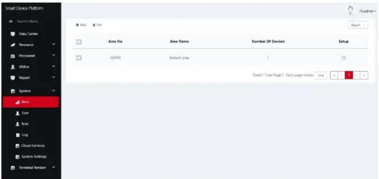
Figure 5-60
Step 2: Click "Add", enter the newly added area information(Area No., Area Name), as shown in Figure 5-61 below.

Figure 5-61
Step 3: Click "Submit" to complete adding area, as shown in Figure 5-62 below.

Figure 5-62
5.8.1.2 Edit Area
The specific steps are as follows:
Step 1: In the smart device platform interface, click "System→Area" to enter the area management interface, as shown in Figure 5-63 below.

Figure 5-63
Step 2: Click "☐" of the area you want to edit, enter information about the area, click "Submit" to complete area editing, as shown in Figure 5-64 below.

Figure 5-64
5.8.1.3 Delete Area
The specific steps are as follows:
Step 1: In the smart device platform interface, click "System→Area" to enter the area management interface, as shown in Figure 5-65 below.

Figure 5-65
Step 2: Click the area you want to delete "→Confirm" to complete the area deletion.

NOTE
● The default area can only be edited and cannot be deleted.
5.8.2 User
User management is used to view, add, edit, and delete smart device platform accounts.
5.8.2.1 Add users
The specific steps are as follows:
Step 1: In the smart device platform interface, click "System→User" to enter the user management interface, as shown in Figure 5-66 below.
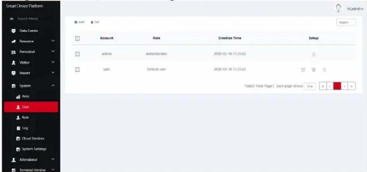
Figure 5-66
Step 2: Click "Aid", enter account, password, confirm password, select authority authorization, as shown in Figure 5-67 below.

Figure 5-67
Step 3: Click "Submit" to complete user addition, as shown in Figure 5-68 below.

Figure 5-68

NOTE
- The default permissions of the system are only for the administrator and the default user. If you need to modify it, you need to go to the role management interface to add roles as needed.
5.8.2.2 Edit User
The specific steps are as follows:
Step 1: In the smart device platform interface, click "System→User" to enter the user management interface, as shown in Figure 5-69 below.

Figure 5-69
Step 2: Click "☐" of the user you want to edit, enter account and permissions, click "Submit" to complete the user editing, as shown in Figure 5-70 below.

Figure 5-70
5.8.2.3 Delete User
The specific steps are as follows:
Step 1: In the smart device platform interface, click "System→User" to enter the user management interface, as shown in Figure 5-71 below.

Figure 5-71
Step 2: Click the account you want to delete →Confirm" to complete the account deleting.

NOTE
● The administrator account can only be edited and cannot be deleted.
5.8.3 Role
Role management configures user roles with different permissions according to actual needs, you can add, edit, and delete roles.
5.8.3.1 Add Role
The specific steps are as follows:
Step 1: In the smart device platform interface, click "System→Role" to enter the role management interface, as shown in Figure 5-72 below.

Figure 5-72
Step 2: Click +dd", enter role name and configure permissions, as shown in Figure 5-73 below.
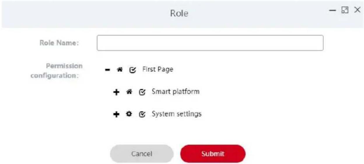
Figure 5-73
Step 3: Click "Submit" to complete the role addition, as shown in Figure 5-74 below.

Figure 5-74
5.8.3.2 Edit Role
The specific steps are as follows:
Step 1: In the smart device platform interface, click "System→Role" to enter the user management interface, as shown in Figure 5-75 below.

Figure 5-75
Step 2: Click "☐" of the role you want to edit, modify role name and permission configuration, click "Submit" to complete the user editing, as shown in Figure 5-76 below.
Role
- □ ×
Role Name:
Normal User
Permission configuration:


First Page


Smart platform

Data center


Resource


Personnel


Visitor


Report


System settings


System


Terminal version
Cancel
Submit
Figure 5-76
5.8.3.3 Delete Role
The specific steps are as follows:
Step 1: In the smart device platform interface, click "System→Role" to enter the user management interface, as shown in Figure 5-77 below.
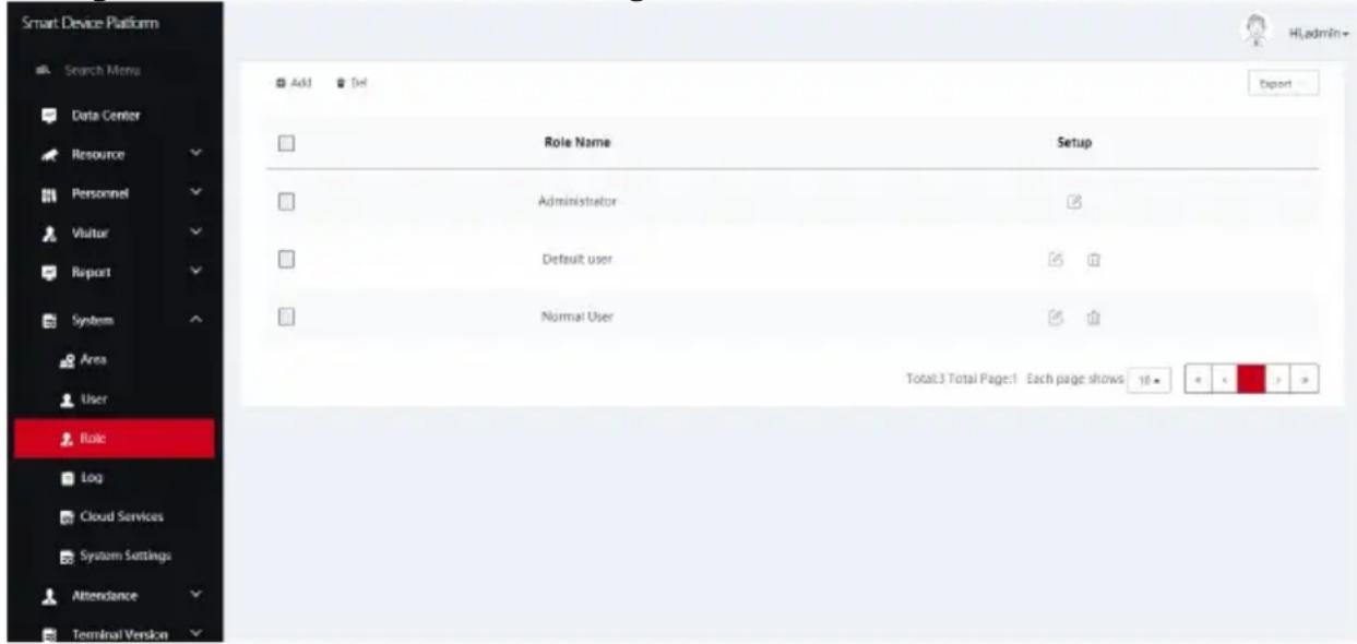
Figure 5-77
Step 2: Click the role you want to delete "→Confirm" to complete role deletion.

NOTE
● The administrator role can only be edited and cannot be deleted.
5.8.4 Log
Log management is used to query and export all platform logs.
5.8.4.1 Query log
The specific steps are as follows:
Step 1: In the smart device platform interface, click "System→Log" to enter the log management interface, as shown in Figure 5-78 below.
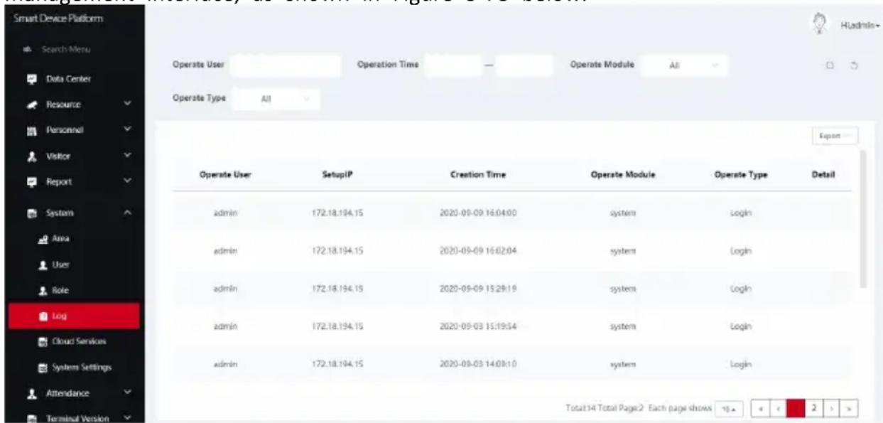
Figure 5-78
Step 2: View the logs.
Query log, at the top of the log management interface, enter a piece of information related to the query log(Such as Operate User, Operation Time, Operate Module, Operate
Type), click " " and logs that match the search criteria are displayed in the log list, as shown in Figure 5-79 below.
| Operate User | SetupIP | Creation Time | Operate Module | Operate Type | Detail |
| admin | 172.18.194.15 | 2020-09-09 16:04:00 | system | Login | |
| admin | 172.18.194.15 | 2020-09-09 16:02:04 | system | Login | |
| admin | 172.18.194.15 | 2020-09-09 15:29:19 | system | Login | |
| admin | 172.18.194.15 | 2020-09-03 15:19:54 | system | Login | |
| admin | 172.18.194.15 | 2020-09-03 14:09:10 | system | Login |
Figure 5-79
5.8.4.2 Export log
The specific steps are as follows:
Step 1: In the smart device platform interface, click "System→Log" to enter the log management interface.
Step 2: click "Export", select the file format (CSV/TXT/Word/Excel), and export the searched logs in a file format.
5.8.5 Cloud Service
Cloud services are used to activate cloud services. After the cloud services of an enterprise are activated, devices can be managed remotely through the mobile terminal.
The specific steps are as follows:
Step 1: In the smart device platform interface, click "System→Cloud Services" to enter the cloud service interface, as shown in Figure 5-80 below.

Figure 5-80
Step 2: Click "Open", enter enterprise code, as shown in Figure 5-81 below.

Figure 5-81
Step 3: Click "Confirm" to activate the cloud service.

NOTE
● The enterprise code is provided by the supplier, the platform and the App use the same enterprise code, and the App can be used normally.
5.8.6 System Settings
System settings are used to set the language of the smart device platform.
The specific steps are as follows:
Step 1: In the smart device platform interface, click "System→Cloud Services" to enter the system setting interface, as shown in Figure 5-82 below.

Figure 5-82
Step 2: Click "Please select", choose a language, as shown in Figure 5-83 below.

Figure 5-83
Step 3: Click "Save" to save setting, the system will automatically switches languages.
5.9 Attendance
Attendance management manages staff attendance and queries attendance records by setting attendance points and attendance solutions.
5.9.1 Attendance Point
Attendance point means the place of attendance, such as the front desk or the office doc. Here you can add, edit and delete attendance points.
5.9.1.1 Add Attendance Point
The specific steps are as follows:
Step 1: In the smart device platform interface, click "Attendance→Attendance Point" to enter the Attendance point interface, as shown in Figure 5-84.

Figure 5-84
Step 2: Click "add" as shown in Figure 5-85.

Figure 5-85
Step 3: Fill in the attendance point information (attendance point name, area, attendance device), and click "Submit" to complete the attendance point addition, as shown in Figure 5-86 below.

Figure 5-86
5.9.1.2 Edit Attendance Point
The specific steps are as follows:
Step 1: Click "Attendance Management → Attendance Point" on the smart terminal platform interface to enter the attendance point interface, as shown in Figure 5-87.

Figure 5-87
Step 2: Click " " of the attendance point to be edited, as shown in Figure 5-88.

Figure 5-88
Step 3: Modify the attendance point information (name, area and attendance equipment), and click "Submit" to complete the modification.
5.9.1.3 Delete Attendance Point
The specific steps are as follows:
Step 1: Click "Attendance Management → Attendance Point" on the smart terminal platform interface to enter the attendance point interface, as shown in Figure 5-89.

Figure 5-89
Step 2: Click "→OK" to complete the attendance point to be deleted, as shown in Figure 5-90.

Figure 5-90

NOTE
- You can select multiple attendance points to be deleted, and click
" ☑ to delete multiple attendance points at the same time.
5.9.2 Attendance Program
Set the attendance solution according to the actual needs of each department, such as working hours of the business department and the R&D department.
5.9.2.1 New Attendance Program
The specific steps are as follows:
Step 1: Click "Attendance Management→ Attendance Program" on the smart terminal platform interface to enter the attendance program setting interface, as shown in Figure 5-91.

Figure 5-91
Step 2: Click "Add" to set the attendance solution (set solution name, select applicable department, set attendance time, working day and overtime status), as shown in Figure 5-92 below.

Figure 5-92
Step 3: Click "Confirm" to complete the new attendance solution, as shown in Figure 5-93 below.

Figure 5-93

NOTE
● Support to set the attendance of multiple departments at the same time when set the attendance program.
● Each department can set up an attendance program.
5.9.2.2 Edit Attendance Program
The specific steps are as follows:
Step 1: Click "Attendance Management→ Attendance Program" on the smart terminal platform interface to enter the attendance program setting interface, as shown in Figure 5-94.

Figure 5-94
Step 2: Click " " to edit the attendance solution, as shown in Figure 5-95 below.

Figure 5-95
Step 3: Modify the attendance solution according to actual needs and click "Confirm".
5.9.2.3 Delete Attendance Program
The specific steps are as follows:
Step 1: Click "Attendance Management→ Attendance Program" on the smart terminal platform interface to enter the attendance program setting interface, as shown in Figure 5-96.

Figure 5-96
Step 2: Click "→Confirm" to complete the solution to be deleted, as shown in Figure 5-97 below.

Figure 5-97

NOTE
- You can select multiple attendance solutions, then click " " to delete multiple attendance solutions at the same time.
5.9.3 Check-In Record
The clock-in/out record is used to view and export the records of personnel in various departments, including time, place and times of clock-in/out.
5.9.3.1 View Clock-in Record
The specific steps are as follows:
Step 1: Click "Attendance Management→Check-In Record" on the smart terminal platform interface to enter the attendance check-in/out record setting interface, as shown in Figure 5-98.

Figure 5-98
Step 2: View all the visitor records in the visitor list (displayed in order from now to the

past), and you can turn the page through " "

NOTE
- You can fill the clock-in/out information (such as personnel number, name, department name, clock-in/out area, clock-in/out device, clock-in/out time) in the clock-in/out record interface, and click "Q", then the search result will be displayed in the list.
5.9.3.2 Export Clock-in/out Record
The specific steps are as follows:
Step 1: Click "Attendance Management→Check-In Record" on the smart terminal platform interface to enter the attendance check-in/out record setting interface.
Step 2: Click "Export", then select the file format (CSVTEXT/Word/Excel) to export the file.
5.9.4 Attendance Record
Attendance record is used to view and export the attendance status of personnel in various departments, such as normal, absent, leave early, and overtime.
5.9.4.1 View Attendance Record
The specific steps are as follows:
Step 1: Click "Attendance Management→ Attendance Record" on the smart terminal platform interface to enter the attendance record interface, as shown in Figure 5-99.

Figure 5-99
Step 2: View all the visitor records in the visitor list (displayed in order from now to the

past), and you can turn the page through " "

NOTE
- You can fill the attendance information (such as personnel number, name, department name, clock-in/out area, clock-in/out device, clock-in/out time) in the attendance record interface, and click "Q", then the search result will be displayed in the list.
5.9.4.2 Export Attendance Record
The specific steps are as follows:
Step 1: Click "Attendance Management→ Attendance Record" on the smart terminal platform interface to enter the attendance record interface.
Step 2: Click "Export", and select the file format (CSV/TXT/Word/Excel) to export the file.
5.10 Terminal version
5.10.1 Firmware
The firmware version is used for storage, delete the firmware version.
5.10.1.1 Storage firmware
The specific steps are as follows:
Step 1: In the smart device platform interface, click "Terminal Version→Firmware" to enter the firmware version interface, as shown in Figure 5-100 below.

Figure 5-100
Step 2: Click " + Add", enter the version name and version description, click "Select File" to select the firmware files, as shown in Figure 5-101 below.

Figure 5-101
Step 3: Click "Submit", the firmware was successfully uploaded to the platform, as shown in Figure 5-102 below.

Figure 5-102
5.10.1.2 Delete firmware
The specific steps are as follows:
Step 1: In the smart device platform interface, click "Terminal Version→Firmware" to enter the firmware version interface, as shown in Figure 5-103 below.

Figure 5-103
Step 2: Click the firmware you want to delete" →Confirm" to complete the firmware deletion.
5.11 Platform Account
The platform account is used to modify the login password, log out of the platform and view the platform version.
5.11.1 Modify Password
The specific steps are as follows:

Step 1: In the smart device platform interface, click "→Modify Password", as shown in Figure 5-104 below.

pie
| Category | Count | |----------------------|-------| | Equipment statistics | 2 | | Personnel statistics | 8 | | Visitor statistics | 0 | | Trend distribution | 0 |Figure 5-104
Step 2: Enter new password and confirm password, click "Submit" to complete the modification of login password, as shown in Figure 5-105 below.

Figure 5-105
5.11.2 Exit the platform
The specific steps are as follows:

Step 1: In the smart device platform interface, click "→Exit", as shown in Figure 5-106 below.

pie
| Statistic | Count | | ---------------------- | ----- | | On Line 1 | 2 | | On Line 7 | 2 | | Entity | 8 | | Seen | 8 | | Seen | 8 | | Seen | 8 | | Seen | 8 | | Seen | 8 | | Seen | 8 | | Seen | 8 | | Seen | 8 | | Seen | 8 | | Seen | 8 | | Seen | 8 | | Seen | 8 | | Seen | 8 | | Seen | 8 | | Seen | 8 | | Seen | 8 | | Seen | 8 | | Seen | 8 | | Seen | 8 | | Seen | 8 | | Seen | 8 | | Seen | 8 | | Seen | 8 | | Seen | 8 | | Seen | 8 | | Seen | 0 | | Historical visits | 0 | | No visit | 0 | | No visited | 0 | | Today | 0 | | Today | 0 | | Today | 0 | | Today | 0 | | Today | 0 | | Today | 0 | | Today | 0 | | Today | 0 | | Today | 0 | | Today | 0 | | Today | 0 | | Today | 0 | | Today | 0 | | Today | 0 | | Today | 0 | | Today | 0 | | Today | 0 | | Today | 0 | | Today | 0 | | Today | 0 | | Today | 0 | | Today | 0 | | Today | 0 | | Today | 0 | | Today | 0 | | Today | 0 | | Today | 0 | | Today | 0 | | Today | 0 | | Today | 0 | | Today | 0 | | Today | 0 | | Today | 0 | | Today | 0 | | Today | 0 | | Today | 0 | | Today | 0 | | Today | 0 | | Today | 0 | | Today | 0 | | Today | 0 | | Today | 0 | | Today | 0 | | Today | 0 | | Today | 0 | | Today | 0 | | Today | 0 | | Today | 0 | | Today | 0 | | Today | 0 | | Today | 0 | | Today | 0 | | Today | 0 | | Today | 0 | | Today | 0 | | Today | 0 | | Today | 0 | | Today | 0 | | Today | 0 | | Today | 0 | | Today | 0 | | Today | 0 | | Today | 0 | | Today | 0 | | Today | 0 | | Today | 0 | | Today | 0 | | Today | 0 | | Today | 0 | | Today | 0 | | Today | 0 | | Today | 0 | | Today | 0 | | Today | 0 | | Today | 0 | | Today | 0 | | Today | 0 | | Today | 0 | | Today | 0 | | Today | 0 | | Today | 0 | | Today | 0 | | Today | 0 | | Today | 0 | | Today | 0 | | Today | 0 | | Today | 0 end | Trend distribution Visitor trends: 2020-06-18 - 2020-06-24 : day - monthFigure 5-106
Step 2: The platform exits and returns to the login interface, as shown in Figure 5-107 below.

Figure 5-107
5.11.3 View version
The specific steps are as follows:

Step 1: In the smart device platform interface, click "", as shown in Figure 5-108 below.

Figure 5-108
Step 2: Check the current version of the platform is "V2.4.1", as shown in Figure 5-109 below.

Hi,admin
Modify Password

Exit
V2.4.1
Figure 5-109
Chapter 6 WEB Operation

NOTE
- Different types of devices have different interface displays. The following pictures are for reference only. Please refer to the actual ones.
● The device supports accessing and managing devices on the PC through the Web. - The WEB page provides application modules such as real-time preview, playback, configuration, and logout.
- The device supports a variety of browser monitoring, such as IE browser, 360 browser, Firefox browser (52 or less version), Google Chrome (Chrome 45 or less version).
- Users can access the device's WEB control interface through multiple PCs at the same time.
6.1 Internet connection
Before using the browser to log in to the web interface, check whether the network between the PC and the device is normal.
Step 1: Confirm that the device is properly connected to the network.
Step s 2: Set the IP address, subnet mask, and gateway for the PC and NVR devices, respectively.
√ If there is no routing device on the network, allocate the IP address of the same network segment: If there is a routing device on the network, you need to set the corresponding gateway and subnet mask.
√ The default IP address of the NVR device is 192.168.1.88.
Step s 3: Check whether the network between the PC and the device is normal. The method is as follows: When the network between the PC and the device is normal, you can log in to the web interface of the device through the PC.
√ On the PC, ping***.***.***.*** (device IP address) verifies that the network is connected and the returned TTL value is generally equal to 255.
6.2 Browser Login
To make sure device connects to Internet successfully, open Browser, input required IP address, the default setting is 192.168.1.88:7080, and enter the login interface, as below Figure 6-1.

Figure 6-1
Select the system language in the upper right corner of the interface (currently supports English, Italian, Spanish, Russian, Arabic, Polish, Japanese, French, Turkish, the default is English), enter the user name and password, the default user name is "admin", the password is "12345", click "Login" Remote login.

NOTE
- If you have modified the IP address of the device, please log in with the newly set IP address.
6.3 Picture
In the picture interface, you can view and download all the pictures captured on the device side. The Step s are as follows:
Step 1: After logging in to the web page, click "Picture" to enter the picture interface, as shown in Figure 6-2 below.

Figure 6-2
Step 2: Set search conditions (time, temperature).
Step 3: Click "", the searched image is displayed on the right side of the interface, as shown in Figure 6-3.


Figure 6-3
Step s 4: Select the picture, click "Download" to select the storage path, click "OK", select
the image to download to the specified folder. Click on the "corresponding to the preview position to view the image.
➢ Start/End Time: The time range for capturing image files.
Query: Click "____", the system will query the corresponding picture file according to the set channel, event type and time range, and display it in the file list.
Details: The image searched by clicking "≡" is displayed in the list as detailed information.
Big icon: The image searched by clicking "☐" is displayed in the list as a large icon.
Download: Select the picture, click "Download", select the storage path, click "OK", select the picture to download to the specified folder.
6.4 Configuration
6.4.1 System
6.4.1.1 System Configuration
■ Version Info
After logging in to the web page, click "Configuration→System→System configuration→Version Info" to enter the version Information interface, as shown in Figure 6-4 below. Here you can view the basic information of the current device.
| Version Info | Date | Dst | Maintain | Display Configuration |
| Serial Number: | 7101553033514 | |||
| Model No.: | FK03AYW | |||
| Firmware Version: | FK03AYWEN_MX806_V20.3.33.3 | |||
| Date: | Aug 12 2020 05:25:28 | |||
| WEB Version: | 20.1.33.200812 | |||
Figure 6-4
[Serial number] The serial number of the device.
[Model NO.] The model of the device.
[Firmware Version] The firmware version of the device.
[Date] The release date of the device version.
[WEB Version] The current web version.
Date
Step 1: After logging in to the web page, click "Configuration→ System→ System configuration → Date" to enter the date setting interface, as shown in Figure 6-5 below.

Figure 6-5
Step 2: Choose how to set the time.
There are ways to set the time "Time Zone", "Synchronize with the computer", "Receive date/time form NTP". When you choose "Receive date/time form NTP", you need to set the NTP server, port and update time.
Step 3: Click"Save" to complete setting.
Dst
Step 1: After logging in to the web page, click "Configuration→ System→ System configuration→ Dst" to enter the daylight saving time interface, as shown in Figure 6-6 below.

Figure 6-6
Step 2: To enable daylight saving time, select the type, set the time range, Offset.
Step 3: Click"Save" to complete the setting.
■ Maintain
After logging in to the web page, click "Configuration→System→ System configuration→ Maintain" to enter the maintain interface, as shown in Figure 6-7 below. Here you can reboot the device, restore the factory settings, and upgrade.

Figure 6-7
[Reboot System] Click "reboot→confirm", the device starts to reboot.
[Restore factory setting] after the device is restored to the factory settings, all parameter settings will be automatically restored to the default parameters (please operate this function carefully).
[Upgrade] Click "Browse" on the right of the upgrade file to select the upgrade file package, and click "Upgrade" to enter the device program upgrade. Do not cut off the power of the device during the upgrade process. Wait for the upgrade progress to complete (please proceed with caution, the wrong upgrade file will cause the device system to run abnormally).
[Manual Online Upgrade]
Step 1: Click "Online Test", when there is a new version, prompt whether to download, click "OK" to automatically download the new version to the default path.
Step 2: The system prompts if you are sure to upgrade the new version, click "Upgrade". The device starts to upgrade and prompts "Do not power off during device upgrade". After the upgrade is complete, the device will reboot and use the latest version of the program.
[Auto Online Upgrade]
Check "Automatic online upgrade", a certain day of the week (this time can be set as needed), the device automatically detects whether there is a new version online, when it displays "New version detected. Is it updated", click "Upgrade". The device starts to upgrade and prompts "Do not power off during device upgrade". After the upgrade is complete, the device will reboot and use the latest version of the program.
![Mach Power AC-DACWT-026 - [Auto Online Upgrade] - 1](/content/2026/06/1212571/images/62bc2ad2ac4c83d639db87bd4c95c8053cbd1874cec87c58ae9ecf73b8e60218.jpg)
NOTE
- When choosing to upgrade the device online, make sure that the device is properly connected to the network.
■ Display configuration
Step 1: After logging in to the web page, click "Configuration→ System→ System configuration→ Display Configuration" to enter the display configuration interface, as shown in Figure 6-8 below.
| Version Info | Date | Dst | Maintain | Display Configuration |
| Display Configuration | Show Ip Address | ✓ | ||
| Language | English | ✓ | ||
| Device Name | FRD | |||
| Temperature Scale | Celsius | ✓ | ||
Figure 6-8
Step 2: Set the display parameters of the device on the local interface.
Here you can set the device interface, such as Show IP address, Show serial number, Display device name, language, device name, temperature scale.
Step 3: Click"Save" to complete the setting.
■ Snapshot
Step 1: After logging in to the web page, click "Configuration→ System→ System Configuration→ Snapshot" to enter the snapshot interface, as shown in Figure 6-9 below.

Figure 6-9
Step 2: Set the relevant parameters of the device to snapshot.
Here you can save records, save pictures, save time.
Step 3: Click"Save" to complete the setting.
6.4.1.2 Scheduled reboot
■ Scheduled reboot
Step 1: After logging in to the web page, click "Configuration→System→Scheduled Reboot→Scheduled Reboot" to enter the scheduled reboot interface, as shown in Figure 6-10 below.

Figure 6-10
Step 2: Set the time to restart the device.
Here you can set daily, weekly, monthly restart or never restart.
Step 3: Click "Save" to complete the setting.
■ Standby settings
Step 1: After logging in to the web page, click "Configuration→System→Scheduled Reboot→Standby Setting" to enter the standby setting interface, as shown in Figure 6-11 below.

Figure 6-11
Step 2: Set the standby time.
Here you can set never, 5 minutes, 10 minutes and 30 minutes.
Step 3: Click "Save" to complete the setting.
6.4.1.3 Security
After logging in to the web page, click "Configuration→System→Security" to enter the standby setting interface. Here you can add, edit, delete users, or query the current user information. When the current user is the administrator "admin", the user can create other users according to actual needs, up to 10 users can be created. As shown in Figure 6-12 below
| Index | User Name | Security | Level | Modify | Del | |
| 1 | admin | Weak Password | Administrator | Modify | - | |
Figure 6-12
■ Add User
Step 1: Click "Add User" to enter the "User Edit" interface, as shown in Figure 6-13 below.

Figure 6-13
Step 2: Enter user name, password and confirm password, select user level.
Step 3: Click "Ok" to complete the user addition.

CAUTIONS
- In order to improve the security of the product's network use, please change your
user name and password regularly. It is recommended to update and maintain every 3 months. If the device is used in a high security risk environment, it is recommended to update monthly or weekly.
- It is recommended that administrators effectively manage device accounts and user permissions, delete irrelevant users and permissions, and close unnecessary network ports.

NOTE
- The user name of the device is admin, and this user name cannot be modified or deleted.
- When setting the password of the device, the password length is 8-31 characters, and must contain numbers and letters.
The password strength rules are as follows:
- If the password contains three or more character types (numbers, lowercase letters, uppercase letters, special characters), it is a strong password.
- If the password is a combination of numbers and special characters, a combination of lowercase letters and special characters, a combination of uppercase letters and special characters, and a combination of lowercase letters and uppercase letters, it is considered a medium-strength password.
- If the password is a combination of numbers and lowercase letters, the combination of numbers and uppercase letters is a weak password.
- The length of the password is 8 characters. The password contains only one type of character. The password is the same as the user name or the password is the reverse of the user name. The above types of passwords are risk passwords. It is not recommended to set this way.
To better protect your privacy and improve product security, it is recommended that you change the risk password to a high-strength password.
■ Edit users (new users)
Step 1: Select the user to be modified in the user management list, click "Modify" to enter the modify user interface, as shown in Figure 6-14 below.

Figure 6-14
Step 2: Tick "Modify Password", enter the old password, new password and confirm password;
Step 3: Click "Ok" to complete the user editing.

NOTE
● The password setting rules are the same as those when adding users.
Delete User
Step 1: Select the user to be deleted in the user management list and click "Del"; Step 2: Click "Ok" to delete the user.
6.4.1.4 Volume
Step 1: After logging in to the web page, click "Configuration→System→Volume" to enter the volume setting interface, as shown in Figure 6-15 below.

Figure 6-15
Step 2: Use the mouse to drag the progress bar to adjust the volume.
Step 3: Click "Save" to complete the setting.
6.4.1.5 Light
Step 1: After logging in to the web page, click "Configuration→System→Light" to enter the light setting interface, as shown in Figure 6-16 below.

Figure 6-16
Step 2: Use the mouse to drag the progress bar to adjust the screen brightness, turn on the fill light.
Step 3: Click "Save" to complete the setting.
6.4.1.6 Wiegand
Step 1: After logging in to the web page, click "Configuration→System→Wiegand" to enter the Wiegand setting interface, as shown in Figure 6-17 below.

Figure 6-17
Step 2: Set Wiegand direction in the drop-down box.
When the Wiegand interface (D0, D1, GND) of the device is connected to a third-party verification device (such as a card reader) that supports Wiegand protocol, select "Input".
Step 3: Click "Save" to complete the setting.
6.4.2 Local network
6.4.2.1 Basic configuration
TCP/IP
The network interface is used to modify the network parameters of the device.
The specific steps are as follows:
Step 1: After logging in to the web page, click "Configuration→ Network→ Basic Setup → TCP/IP" to enter the TCP/IP interface, as shown in Figure 6-18 below.
| TCP/IP | |
| Enable dhcp | ☐ |
| IP address | 172.18.195.251 |
| Network mask | 255.255.248.0 |
| Gateway | 172.18.192.1 |
| Device mac | 2C:6F:51:03:DC:03 |
| Primary dns | 172.18.192.1 |
| Secondary dns | 8.8.8.8 |
Figure 6-18
Step 2: Modify network parameters (enable dhcp, IP address, Network mask, Gateway, Device mac, Primary dns, and Secondary dns).
Step 3: Click "Save" to complete the setting.
6.4.2.2 Advanced configuration
■ MQTT Configuration
MQTT(Message Queuing Telemetry Transport) protocol, that is, message queue telemetry transport protocol.
The specific steps are as follows:
Step 1: After logging in to the web page, click "Configuration→Network→Advance Setup→MQTT Configuration" to enter the MQTT protocol configuration interface, as shown in Figure 6-19 below.

Figure 6-19
Step 2: Enable "MQTT", enter the user name, password, port and other parameters, enter the subscription setting and issue setting.
Step 3: Click "Save" to complete the setting.
■ SMTP Configuration
The specific steps are as follows:
Step 1: After logging in to the web page, click "Configuration→Network→Advance Setup→SMTP Configuration" to enter the SMTP setting interface, as shown in Figure 6-20 below.
□ Enable E-mail Alarm Notifications
| SMTP Server | Custom |
| Custom SMTP Server | smtp.MailServer.com |
| Sender's Address | User@domain.com |
| Port | 465 |
□ Attach File
| Subject | FRD ALERT |
| Encryption | SSL |
| User Name | User |
| Password | ********** |
| Recipient1 | receiver1@domain.com |
| Recipient2 | receiver2@domain.com |
| Recipient3 | receiver3@domain.com |

Figure 6-20
Step 2: Enable email alarm notification and set email related information.
Set the SMTP server, port, sender, recipient address, attach file and other information here.
Step 3: Click "Save" to complete the setting.
Sender
【SMTP Server】Enter the server address of the sender mailbox.
【Sender's Address】Enter the complete address of the sender mailbox.
【Port】Enter the server port of the sender mailbox.
【User Name】Enter the user name of the sender mailbox.
【Password】Enter the password of the sender mailbox.
Recipient
【Recipient 1, 2, 3】Fill in the complete address of the inbox, up to 3 inboxes are supported here. After completing, you can click "Test" to ensure the correctness of all input information and network connectivity of the device.
■ Wi-Fi Configuration
The specific steps are as follows:
Step 1: After logging in to the web page, click "Configuration→Network→Advance setup→Wi-Fi Configuration" to enter the Wi-Fi configuration interface, as shown in Figure 6-21 below.

Figure 6-21
Step 2: Turn on the wireless network function and click "Save".
Step 3: The interface automatically searches for nearby Wi-Fi hotspots, selects the Wi-Fi hotspot, enters the corresponding password in the Key column, and clicks "Connection".

NOTE
- Only device that support the Wi-Fi function have a Wi-Fi interface. Please refer to the specific function of the device.
- Up to 3 connected Wi-Fi accounts can be remembered in my network for users to switch Wi-Fi.
6.4.3 Face recognition
Step 1: After logging in to the web page, click "Configuration→Face recognition→Face recognition" to enter the face recognition interface, as shown in Figure 6-22 below.
Face Recognition
Stranger Passage

Detection Mask

Relay Time:
1000

(Millisecond)
Relay Direction:
Normal

Living Body:
Close

Thermal Map:
Close

Verification Mode:
Face Verification

Save
Figure 6-22
Step 2: Configure the relevant parameters for face recognition.
Here, you can enable the stranger passage, detection mask, living body, thermal map, set the relay time and relay direction.
Step 3: Click "Save" to complete the setting.
【Stranger Passage】Turn on/off the pass function for strangers (unregistered persons).
【Detection Mask】Turn on/off the device to check the mask function.
【Relay Time】The duration of the relay on/off.
【Relay Direction】When the external access control device is connected to the relay port NO and COM, the relay direction selects "Normal"; when the external access control device is connected to the relay port NC and COM, the relay direction selects "Reverse".
【Living Body】Turn on/off the live detection function of the device. After being turned on, it can effectively resist common frauds such as photos, videos, face changes, masks, and occlusions.
【Thermal Map】Turn on/off the heat map displayed on the device screen.
【Verification Mode】Choose the verification method according to actual needs.
【Face Verification】 The device can pass the access control after it recognizes the registered person.
【Card Verification】Registered persons can pass the access control by swiping their cards, while unregistered persons can pass the access control by swiping their cards after the "Stranger Passage" function is turned on.
【Face and Card Verification】The device performs face recognition first. After the device recognizes the face, it prompts "Please swipe your card", and then swipe your card to pass the access control.
6.4.4 Temperature
Step 1: After logging in to the web page, click "Configuration → Temperature→ Temperature" to enter the temperature measurement configuration interface, as shown in Figure 6-25 below.
Temperature
Temperature compensation:
0.0
Compensation range -5.00\~5.00
Temperature check

Alarm temperature
37.3

Save
Figure 6-25
Step 2: Configure the relevant parameters for temperature.
Here, you can enable temperature check, set temperature compensation and alarm temperature.
Step 3: Click "Save" to complete the setting.
6.4.5 Personnel Inquiry
Step 1: After logging in to the web page, click "Configuration→ Personnel inquiry → Personnel inquiry" to enter the personnel inquiry interface, as shown in Figure 6-26 below.
| Index | User id | Name | Effective start time | Effective end time |
| 1 | 6 | zhangle10405 | Not limited | Not limited |
| 2 | 7 | zhangle12001 | Not limited | Not limited |
| 3 | 8 | zhangle12002 | Not limited | Not limited |
| 4 | 9 | zhangle12003 | Not limited | Not limited |
| 5 | 10 | zhangle12004 | Not limited | Not limited |
| 6 | 11 | zhangle12005 | Not limited | Not limited |
| 7 | 12 | zhangle12006 | Not limited | Not limited |
| 8 | 13 | zhangle12007 | Not limited | Not limited |
| 9 | 14 | zhangle12008 | Not limited | Not limited |
| 10 | 15 | zhangle12009 | Not limited | Not limited |
| 11 | 16 | zhangle12010 | Not limited | Not limited |
| 12 | 17 | zhangle12011 | Not limited | Not limited |
| 13 | 18 | zhangle12012 | Not limited | Not limited |
| 14 | 19 | zhangle12013 | Not limited | Not limited |
| 15 | 20 | zhangle12014 | Not limited | Not limited |
| 16 | 21 | zhangle12015 | Not limited | Not limited |
| 17 | 22 | zhangle12016 | Not limited | Not limited |
| 18 | 23 | zhangle12017 | Not limited | Not limited |
| 19 | 24 | zhangle12018 | Not limited | Not limited |
| 20 | 25 | zhangle12019 | Not limited | Not limited |
| 21 | 26 | zhangle12020 | Not limited | Not limited |
| 22 | 27 | zhangle12021 | Not limited | Not limited |
| 23 | 28 | zhangle12022 | Not limited | Not limited |
Figure 6-26
Step 2: View information about storage personnel in the device.
Step 3: Enter the page number at the jump position, click "Go", the interface jumps to the specified interface.
Chapter 7 WEB Operation (Type F &G)

NOTE
- Different types of devices have different interface displays. The following pictures are for reference only. Please refer to the actual ones.
● The device supports accessing and managing devices on the PC through the Web. - The WEB page provides application modules such as real-time preview, playback, configuration, and logout.
- The device supports a variety of browser monitoring, such as IE browser, 360 browser, Firefox browser (52 or less version), Google Chrome (Chrome 45 or less version).
- Users can access the device's WEB control interface through multiple PCs at the same time.
- This chapter applies to face recognition terminal type F & type G devices. Type G device does not have a temperature measurement module, so Type G device does not have a temperature-related interface. Please refer to the actual product.
7.1 Internet connection
Before using the browser to log in to the web interface, check whether the network between the PC and the device is normal.
Step 1: Confirm that the device is properly connected to the network.
Step 2: Set the IP address, subnet mask, and gateway for the PC and NVR devices, respectively.
√ If there is no routing device on the network, allocate the IP address of the same network segment: If there is a routing device on the network, you need to set the corresponding gateway and subnet mask.
√ The default IP address of the NVR device is 192.168.1.88.
Step 3: Check whether the network between the PC and the device is normal. The method is as follows: When the network between the PC and the device is normal, you can log in to the web interface of the device through the PC.
√ On the PC, ping***.***.***.*** (device IP address) verifies that the network is connected and the returned TTL value is generally equal to 255.
7.2 Browser Login
To make sure device connects to Internet successfully, open Browser, input required IP address, the default setting is 192.168.1.88, and enter the login interface, as below Figure 7-1.

Figure 7-1
Select the system language in the upper right corner of the interface, enter the user name and password, the default user name is "admin", the password is "12345", click "Login" Remote login.

NOTE
- If you have modified the IP address of the device, please log in with the newly set IP address.
7.3 My Device
After logging in to the web page, it will automatically enter the "My Device" interface, where you can view the device's real-time video, face gallery, pass, abnormal temperature data, version information, and operating status, as shown in Figure 7-2 below.

Figure 7-2
[Device Model] Device model.
[Serial Number] The serial number for the device.
[Firmware Version] The version information for the device software program.
[Web Version] Current web page version.
7.4 Record
Local records are used to view and download access records and temperature measurement records.
7.4.1 Pass Record
The specific steps are as follows:
Step 1: After logging in to the web page, click "Record → Pass Record" to enter the pass record interface.
Step 2: Set the search criteria (search time range, name).
Step 3: Click "Query", the searched pictures are displayed in the list in the form of detailed information, as shown in Figure 7-3 below.

Figure 7-3

NOTE
- After searching the pass records, please select the record you want to download and click "Download". Then select the download path and click "Download" to complete the download.
7.4.2 Temperature Measurement Record
The specific steps are as follows:
Step 1: After logging in to the web page, click "Record → Temperature Measurement Record" to enter the temperature measurement record interface.
Step 2:Set the search criteria (search time range, name).
Step 3: Click "Query", the searched pictures are displayed in the list in the form of detailed information, as shown in Figure 7-4 below.

Figure 7-4

NOTE
- After searching the temperature measurement record, please select the record to be downloaded and click "Download". Select the download path and click "Download" to complete the download.
7.5 System Configuration
System consists of system, network configuration, user rights, and equipment maintenance, and is mainly used to configure the basic functions of the device.
7.5.1 System
The system consists of date, daylight saving time, image configuration, display configuration, sound configuration, fill light configuration and maintenance.
Date
The specific steps are as follows:
Step 1: After logging in to the web page, click "System → System → Date" to enter the date setting interface, as shown in Figure 7-5 below.

Figure 7-5
Step 2: Choose how to set the time.
There are ways to set the time "Time Zone", "Synchronize with the computer", "Receive date/time form NTP". When you choose "Receive date/time form NTP", you need to set the NTP server, port and update time.
Step 3: Click "Save" to complete setting.
■ DST
Step 1: After logging in to the web page, click "System → System → Dst" to enter the daylight saving time interface, as shown in Figure 7-6 below.

Figure 7-6
Step 2: To enable daylight saving time, select the type, set the time range, Offset.
Step 3: Click"Save" to complete the setting.
■ Image Configuration
Step 1: After logging in to the web page, click "System → System → Image Configuration" to enter the image configuration interface, as shown in Figure 7-7 below.

Figure 7-7
Step 2: Enable HDR, Beauty,and set related values.
Step 3: Click"Save" to complete the setting.
■ Display Configuration
Step 1: After logging in to the web page, click "System → System → Display Configuration" to enter the display configuration interface, as shown in Figure 7-8 below.

Figure 7-8
Step 2: Set the display parameters of the device on the local interface. Here you can set the device interface, such as Show IP Address, Show Serial Number, Display Device Name, Language, Device Name, Screen Brightness Setting. Step 3: Click"Save" to complete the setting.
■ Sound Configuration
Step 1: After logging in to the web page, click "System→System→Sound Configuration" to enter the sound configuration interface, as shown in Figure 7-9 below.

Figure 7-9
Step 2: Use the mouse to drag the progress bar to adjust the volume.
Step 3: Click"Save" to complete the setting.
■ Fill Light Configuration
Step 1: After logging in to the web page, click "System → System → Fill Light Configuration" to enter the light setting interface, as shown in Figure 7-10 below.

Figure 7-10
Step 2: Turn on the fill light, and use the mouse to drag the progress bar to adjust the screen brightness.
Step 3: Click"Save" to complete the setting.
- Maintain
Step 1: After logging in to the web page, click "System → System → Maintain" to enter the maintain interface, as shown in Figure 7-11 below. Here you can reboot the device, restore the factory settings, and upgrade.

Figure 7-11
[Reboot System] Click "reboot→confirm", the device starts to reboot.
[Restore factory setting] after the device is restored to the factory settings, all parameter settings will be automatically restored to the default parameters (please operate this function carefully).
[Upgrade] Click "Browse" on the right of the upgrade file to select the upgrade file package, and click "Upgrade" to enter the device program upgrade. Do not cut off the power of the device during the upgrade process. Wait for the upgrade progress to complete (please proceed with caution, the wrong upgrade file will cause the device system to run abnormally).
[Manual Online Upgrade]
Step 1: Click "Online Test", when there is a new version, prompt whether to download, click "OK" to automatically download the new version to the default path.
Step 2: The system prompts if you are sure to upgrade the new version, click "Upgrade".
The device starts to upgrade and prompts "Do not power off during device upgrade". After the upgrade is complete, the device will reboot and use the latest version of the program.
[Auto Online Upgrade]
Check "Automatic online upgrade", a certain day of the week (this time can be set as needed), the device automatically detects whether there is a new version online, when it displays "New version detected. Is it updated", click "Upgrade". The device starts to upgrade and prompts "Do not power off during device upgrade". After the upgrade is complete, the device will reboot and use the latest version of the program.
![Mach Power AC-DACWT-026 - [Auto Online Upgrade] - 1](/content/2026/06/1212571/images/12ca028a7ea52cd274b35901cc68d06b7d3ac020b589054892c75f061b23c2f8.jpg)
NOTE
- When choosing to upgrade the device online, make sure that the device is properly connected to the network.
7.5.2 Network Configuration
The network configuration consists of TCP/IP, WIFI, 4G, MQTT and SMTP.
TCP/IP
The network interface is used to modify the network parameters of the device.
The specific steps are as follows:
Step 1: After logging in to the web page, click "System → Network Configuration → TCP/IP" to enter the TCP/IP interface, as shown in Figure 7-12 below.

Figure 7-12
Step 2: Modify network parameters (enable dhcp, IP address, Network mask, Gateway, Device mac, Primary dns, and Secondary dns).
Step 3: Click "Save" to complete the setting.
WIFI
The WIFI interface is used to configure the device to connect to the LAN WIFI.
The specific steps are as follows:
Step 1: After logging in to the web page, click "System → Network Configuration → Wi-Fi Configuration" to enter the Wi-Fi configuration interface, as shown in Figure 7-13 below.

Figure 7-13
Step 2: Click "Enable" to enable wireless LAN, click "save".
Step 3: Click the "Scanning" button to search for connectable WIFI hotspots in the LAN.
Step 4: Select the WIFI to be connected, enter the corresponding WIFI password in the key field, and select the encryption method.
Step 5: Click "Enable" to enable DHCP, and click "Save".
[My Network] WIFI IPC can connect the device or delete the WIFI account through wireless WIFI management by remembering the account that has been connected to the WIFI.

NOTE
- When the device is connected to WIFI, you can also choose not to turn on DHCP,
manually input and select the preferred DNS server, IP address, default gateway of the same WIFI network segment, and set the relevant information of the camera WIFI network. Up to 3 connected Wi-Fi accounts can be remembered in my network for users to switch Wi-Fi.
4G
The 4G interface is used to configure the hotspot of the device's wireless network for users to connect.
Prerequisites:
Before using the 4G function of the device, you must ensure that the device has a 4G SII card installed and that the card can access the Internet normally.
The steps to connect the device to 4G are as follows:
Step 1: After logging in to the web page, click "System → Network Configuration → 4G" to enter the 4G configuration interface, as shown in Figure 7-14.

Figure 7-14
Step 2: Click "Enable" to enable 4G, enter APN, username and password
Step 3: Click "Save" to complete the setting.
MQTT
MQTT(Message Queuing Telemetry Transport) protocol, that is, message queue telemetry transport protocol.
The specific steps are as follows:
Step 1: After logging in to the web page, click "System → Network Configuration → MQTT Configuration" to enter the MQTT protocol configuration interface, as shown in Figure 7-15 below.

Figure 7-15
Step 2: Enable "MQTT", enter the user name, password, port and other parameters, enter the subscription setting and issue setting.
Step 3: Click "Save" to complete the setting.
SMTP
The specific steps are as follows:
Step 1: After logging in to the web page, click "Configuration → Network → Advance Setup → SMTP Configuration" to enter the SMTP setting interface, as shown in Figure 7-16 below.

Figure 7-16
Step 2: Enable email alarm notification and set email related information.
Set the SMTP server, port, sender, recipient address, attach file and other information here.
Step 3: Click "Save" to complete the setting.
Sender
[SMTP Server] Enter the server address of the sender mailbox.
[Sender's Address] Enter the complete address of the sender mailbox.
[Port] Enter the server port of the sender mailbox.
[User Name] Enter the user name of the sender mailbox.
[Password] Enter the password of the sender mailbox.
Recipient
[Recipient 1, 2, 3] Fill in the complete address of the inbox, up to 3 inboxes are supported here. After completing, you can click "Test" to ensure the correctness of all input information and network connectivity of the device.
7.5.3 User Rights
User permissions are used to manage (add, modify, delete) device users. When the current user is the administrator "admin", the user can create other users according to actual needs, up to 10 users can be created.
■ Add User
The specific steps are as follows:
Step 1: After logging in to the web page, click "System → User Rights" to user management interface, as shown in Figure 7-17 below.

Figure 7-17
Step 2: Click "Add User" to enter the "Add User" interface, as shown in Figure 7-18 below.

Figure 7-18
Step 3: Enter user name, password and confirm password, select user level.
Step 4: Click "Ok" to complete the user addition.

Warning
- In order to improve the security of the product's network use, please change your user name and password regularly. It is recommended to update and maintain every 3 months. If the device is used in a high security risk environment, it is recommended to update monthly or weekly.
- It is recommended that administrators effectively manage device accounts and user permissions, delete irrelevant users and permissions, and close unnecessary network ports.

NOTE
● The user name of the device is admin, and this user name cannot be modified or deleted.
- When setting the password of the device, the password length is 8-31 characters, and must contain numbers and letters.
The password strength rules are as follows:
- If the password contains three or more character types (numbers, lowercase letters, uppercase letters, special characters), it is a strong password.
- If the password is a combination of numbers and special characters, a combination of lowercase letters and special characters, a combination of uppercase letters and special characters, and a combination of lowercase letters and uppercase letters, it is considered a medium-strength password.
- If the password is a combination of numbers and lowercase letters, the combination of numbers and uppercase letters is a weak password.
- The length of the password is 8 characters. The password contains only one type of character. The password is the same as the user name or the password is the reverse of the user name. The above types of passwords are risk passwords. It is not recommended to set this way.
To better protect your privacy and improve product security, it is recommended that you change the risk password to a high-strength password.
■ Edit users (new users)
Step 1: Select the user to be modified in the user management list, click "Modify" to enter the modify user interface, as shown in Figure 7-19 below.

Figure 7-19
Step 2: Tick "Modify Password", enter the new password and confirm password;
Step 3: Click "Ok" to complete the user editing.

● The password setting rules are the same as those when adding users.
Delete User
Step 1: Select the user to be deleted in the user management list and click "Del";
Step 2: Click "Ok" to delete the user.
7.5.4 Equipment Maintenance
Equipment maintenance consists of scheduled restart and standby settings.
■ Scheduled Reboot
The specific steps are as follows:
Step 1: After logging in to the web page, click "System → Equipment Maintenance → Scheduled Reboot" to scheduled reboot interface, as shown in Figure 7-20 below.

Figure 7-20
Step 2: Set the time to restart the device.
Here you can set daily, weekly, monthly restart or never restart.
Step 3: Click "Save" to complete the setting.
■ Standby settings
The specific steps are as follows:
Step 1: After logging in to the web page, click "System → Equipment Maintenance → Standby Settings" to enter the standby setting interface, as shown in Figure 7-21 below.

Figure 7-21
Step 2: Set the standby time.
Here you can set never, 5 minutes, 10 minutes and 30 minutes.
Step 3: Click "Save" to complete the setting.
7.6 Staff
7.6.1 Personnel Inquiry
The specific steps are as follows:
Step 1: After logging in to the web page, click "Staff → Personnel Inquiry" to enter the personnel inquiry interface, as shown in Figure 7-22 below.

Figure 7-22
Step 2: Enter the name of the person to be queried in the input box at the upper right corner of the interface.
Step 3: Click "Query", and the interface displays the information of the searched person (user ID, name, effective start time, effective end time, picture).

NOTE
- Enter the personnel query interface, the system will automatically search and display all personnel information of the equipment.
- Click “ ” to view personnel photos.
7.7 Advance
The advanced configuration consists of verification mode, face recognition, temperature measurement configuration and interface configuration.
7.7.1 Verification Mode
The specific steps are as follows:
Step 1: After logging in to the web page, click "Advance → Verification Mode" to enter the verification mode interface, as shown in Figure 7-23 below.

Figure 7-23
Step 2: Select the verification mode from the drop-down box.
Step 3: Click "Save" to complete the setting.
[Verification Mode] Choose the verification method according to actual needs.
[Face Verification] The device can pass the access control after it recognizes the registered person.
[Swipe] Registered persons can pass the access control by swiping their cards.
[Face + Temperature Measurement] The device will first recognize the face, and after successfully recognizing the face, it will prompt "Please take temperature". When the temperature of the person is displayed as normal, the access control can be passed.
[Face + Swipe] The device will first recognize the face, and after successfully recognizing the face, it will prompt "Please swipe the card". If the card owner is the same as the detected person, the access control can be passed.
[Face + Temperature Measurement+Swipe]The device will first recognize the face, and after successfully recognizing the face, it will prompt "Please take temperature". When the temperature of the person is displayed as normal, it will prompt "Please swipe the card". If the card owner is the same as the detected person, the access control can be passed.
[Face + ID Card]The device will first recognize the face, and after successfully recognizing the face, it will prompt "ID Card". If the ID card owner is the same as the detected person the access control can be passed.
[Face + ID Card + Temperature Measurement]. After the device recognizes the face, it prompts for temperature measurement, and then prompts to swipe the ID card; if the body temperature is normal and the person is judged to be consistent with the ID card, the access control can be passed.
7.7.2 Face Recognition
The specific steps are as follows:
Step 1: After logging in to the web page, click "Advance → Face Recognition" to enter the face recognition interface, as shown in Figure 7-24 below.

Figure 7-24
Step 2: Set face recognition parameters as needed (stranger passage, detection mask, snapshot switch, pass record keeping, relay time, relay direction, live body and thermal map)
Step 3: Click "Save" to complete the setting.
[Stranger Passage] Turn on/off the pass function for strangers (unregistered persons).
[Detection Mask] Turn on/off the device to check the mask function.
[Snapshot Switch] After enabling, the device starts to capture faces and save the pictures.
[Relay Time] The duration of the relay on/off.
[Relay Direction] When the external access control device is connected to the relay port NO and COM, the relay direction selects "Normal"; when the external access control device is connected to the relay port NC and COM, the relay direction selects "Reverse". [Living Body] Turn on/off the live detection function of the device. After being turned on, it can effectively resist common frauds such as photos, videos, face changes, masks, and occlusions.
[Thermal Map] Turn on/off the heat map displayed on the device screen.
7.7.3 Temperature-taking Setting
The temperature measurement configuration interface is used to set temperature parameters and upgrade the temperature measurement module.
The specific steps for setting temperature measurement parameters are as follows:
Step 1: After logging in to the web page, click "Advance → Temperature-taking Setting" to enter the Temperature-taking Setting interface, as shown in Figure 7-25 below.

Figure 7-25
Step 2:Set temperature parameters (temperature compensation, alarm temperature, temperature scale) as required.
Step 3: Click "Save" to complete the setting.
The steps to upgrade the temperature measurement module are as follows
Step 1: After logging in to the web page, click "Advance → Temperature-taking Setting" to enter the Temperature-taking Setting interface.
Step 2: Click "Browse" and select the temperature measurement module upgrade file (eg: LS_HTP_V20.1.XX.X.bin).
Step 3: Click "Upgrade" and wait for the temperature measurement module to be upgraded.

- The upgrade process takes 1-10 minutes, please do not turn off the power, it will automatically restart after the upgrade is completed.
7.7.4 Interface Configuration
The interface configuration consists of disk management, Wiegand and alarm output.
■ HDD
The specific steps are as follows:
Step 1: After logging in to the web page, click "Advance → Interface Configuration → HDD" to enter the HDD Setting interface, as shown in Figure 7-26 below.

Figure 7-26
Step 2: Here you can view the memory card information (serial number, status, total capacity, remaining capacity, device type). You can also select the memory card, click "Format→Ok" to format the memory card.
■ Wiegand
The specific steps are as follows:
Step 1: After logging in to the web page, click "Advance → Interface Configuration → Wiegand" to enter the Wiegand Setting interface, as shown in Figure 7-27 below.

Figure 7-27
Step 2: Set Wiegand direction in the drop-down box.
When the Wiegand interface (D0, D1, GND) of the device is connected to a third-party verification device (such as a card reader) that supports Wiegand protocol, select "Input".
Step 3: Click "Save" to complete the setting.
■ Alarm Output
The specific steps are as follows:
Step 1: After logging in to the web page, click "Advance → Interface Configuration → Alarm Output" to enter the alarm output setting interface, as shown in Figure 7-28 below.

Figure 7-28
Step 2: Click "Enable" to enable the alarm output, and select the alarm output time in the drop-down box.
Step 3: Click "Save" to complete the setting.
7.8 Logout
The specific steps are as follows:

Step 1: After logging in to the web page, click “☐”, in the upper right corner to enter the logout interface, as shown in Figure 7-29.

Figure 7-29
Step 2: Click "OK" to jump to the login interface.
Chapter 8 Appendix
8.1 Common problem introduction
-
How many conditions may cause the device to fail to operate normally after booting? Answer: Check whether the input power is correct; check whether the switch power cord is in normal contact.
-
What effect may the heat dissipation of the device have on itself?
Answer: The operation of the device will generate a certain amount of heat. Please place the device in a safe and well-ventilated place to prevent the device from affecting the stability and service life of the system due to long-term high temperature.
- What should I do if the platform cannot find the device?
Answer:
1) Make sure the power is connected.
2) Make sure that the device network is smooth and connected normally.
3) Make sure that the computer where the device is installed is a windows system, and the computer and the device are on the same LAN.
4) Make sure that the device is fully started, and automatically enter the face recognition interface.
5) Make sure that the current network environment is stable.
- What to do if the network connection is unstable?
Answer:
1) Check if the network is unstable.
2) Check if the IP address conflicts.
3) Check if the MAC address conflicts.
4) Check whether the computer or device network card is abnormal.
- What should I do when SDP2000 is abnormal (such as abnormal reading or abnormal data interface)?

Answer: Right-click on the "icon" in the lower right corner of the desktop, check whether the status of Nginx, Mysqld and SDP2000 is green (normal status), if any item shows a gray status, please restart the Software, make it green, as shown in Figure 4-1 below.

Figure 7-1
- Abnormal temperature always showing 35.8°.
Answer:
1) If version is below V20.1.12.2 please contact technical to upgrade the device.
2) If confirm the firmware version is the latest one, need to disconnect the power and power on again for 5 mins then device can be used normally.
- The image delivery fails which may cause the device not working properly, you need to restart the device.
Answer:
1) If the version is lower than V20.1.12.2, please contact our technicians to upgrade the device program.
2) We need to use pre-processed software tools to process the pictures before importing them to the device. The picture pre-processed software tools can be obtained by contacting the relevant sales or technical person.
3) Enter the computer control panel and turn off the computer's network firewall.
- The web client clicks the device configuration and fails to get the data.
Answer:
1) Removed the network cable from the device, delete the device on the smart terminal platform, and then press the hard reset button to restore the factory. Then you can search and add the device again on the smart terminal platform.
2) If the data acquisition failure still occurs after trying the operation of step 1), after deleting the device on the smart terminal platform, install the smart terminal platform again and search and add the temperature measuring device again.
- There is no sound from the device.
Answer:
1) Go to the computer site of intelligent management terminal, enter the setting interface: Device Management-Configuration-Remote -Configuration, and check if the volume is set to a low value. It is recommended to set it to 75 (factory default).
2) If you confirm that the parameter has a setting of 75, also tried to press the hard-rese button on the device's waterproof cables to restore the device,
3) But if there is still no sound, then the device has speaker failure, and needs to be sent to us for RMA.

- AI Face Recognition Device
- Contents
- Chapter 1 Functions and Features....1
- Chapter 2 Device Introduction....2
- Chapter 3 Installation....18
- Chapter 4 Smart device platform....27
- About this Manual
- Disclaimer
- Data Security Statement
- Safety Precautions
- WARNING
- CAUTION
- NOTE
- Chapter 1 Functions and Features
- Product Manual
- Product Features
- Chapter 2 Device Introduction
- Device Introduction
- Smart Face Recognition Device (Type A Without Temperature Detection)
- Smart Face Recognition Device (Type B Forehead Temperature Detection)
- Smart Face Recognition Device (Type C Wrist Temperature Detection)
- Smart Face Recognition Device (Type D Forehead Temperature Detection)
- Smart Face Recognition Device (Type E Without Temperature Detection)
- Smart Face Recognition Device (Type F Forehead Temperature Detection)
- Smart Face Recognition Device (Type G Without Temperature Detection)
- Device Size
- Smart Face Recognition Device (Type A)
- Smart Face Recognition Device (Type B)
- Smart Face Recognition Device (Type C)
- Smart Face Recognition Device (Type D & E)
- Smart Face Recognition Device (Type F)
- Smart Face Recognition Device (Type G)
- Connector Introduction
- Wire connector (Type A)
- Wire connector (Type B)
- Wire connector (Type C)
- Wire connector (Type D & E)
- Wire connector (Type F & G)
- Chapter 3 Installation
- Installation Environment:
- Installation of Type A, Type B, and Type C Equipment 3.1.1 Installed on the gate
- Install on the desktop
- Install on floor pole bracket
- Wall mounted
- Type D & E equipment installation
- Install on the desktop
- Wall Mounted
- Chapter 4 Smart device platform
- Platform Installation
- Configure the computer
- Software Installation
- Server introduction
- Restart the system software
- Language switch
- Introduction of SDP2000 sever control panel
- Chapter 5 Smart Device Platform Operation
- Smart device platform login
- Smart Device Platform Introduction
- Data Center
- Resource
- Device
- Add device
- The specific steps are as follows:
- ■ Add device manually
- Delete device
- Configure device
- √ Remote Configuration:
- √ Version Info:
- √ Function Parameters Configuration:
- Report Export
- Batch Upgrade Firmware
- Personnel
- Department
- Add Organization
- Edit organization
- Delete organization
- Organization search
- Personnel
- Add personnel in batches
- Staff photo import
- Delete Personnel
- Authorize / Reissue
- Search Personnel
- Visitor
- Visitor Information
- Visitor Registration
- View visitor records
- Report
- Personnel Access
- View Personnel Access
- Export personnel access records
- Abnormal Access
- View Abnormal Access
- Export Abnormal Access
- Visitor
- View Visitor
- Export Visitor
- System
- Area
- Add Area
- Edit Area
- Delete Area
- User
- Add users
- Edit User
- Delete User
- Role
- Add Role
- Edit Role
- Delete Role
- Log
- Query log
- Export log
- Cloud Service
- System Settings
- Attendance
- Attendance Point
- Add Attendance Point
- Edit Attendance Point
- Delete Attendance Point
- Attendance Program
- New Attendance Program
- Edit Attendance Program
- Delete Attendance Program
- Check-In Record
- View Clock-in Record
- Export Clock-in/out Record
- Attendance Record
- View Attendance Record
- Export Attendance Record
- Terminal version
- Firmware
- Storage firmware
- Delete firmware
- Platform Account
- Modify Password
- Exit the platform
- View version
- Chapter 6 WEB Operation
- Internet connection
- Browser Login
- Picture
- Configuration
- System
- System Configuration
- ■ Version Info
- Date
- Dst
- ■ Maintain
- [Manual Online Upgrade]
- [Auto Online Upgrade]
- ■ Display configuration
- ■ Snapshot
- Scheduled reboot
- ■ Scheduled reboot
- ■ Standby settings
- Security
- ■ Add User
- CAUTIONS
- ■ Edit users (new users)
- Delete User
- Volume
- Light
- Wiegand
- Local network
- Basic configuration
- TCP/IP
- Advanced configuration
- ■ MQTT Configuration
- ■ SMTP Configuration
- Sender
- Recipient
- ■ Wi-Fi Configuration
- Face recognition
- Face Recognition
- Save
- Temperature
- Temperature
- Personnel Inquiry
- Chapter 7 WEB Operation (Type F &G)
- Internet connection
- Browser Login
- My Device
- Record
- Pass Record
- Temperature Measurement Record
- System Configuration
- System
- ■ DST
- ■ Image Configuration
- ■ Sound Configuration
- ■ Fill Light Configuration
- - Maintain
- Network Configuration
- WIFI
- 4G
- Prerequisites:
- The steps to connect the device to 4G are as follows:
- MQTT
- SMTP
- User Rights
- Equipment Maintenance
- Staff
- Personnel Inquiry
- Advance
- Verification Mode
- Face Recognition
- Temperature-taking Setting
- Interface Configuration
- ■ Wiegand
- ■ Alarm Output
- Logout
- Chapter 8 Appendix
- Common problem introduction
- Answer:
Brand : Mach Power
Model : AC-DACWT-026
Category : Unspecified