99-7882B - Kit voiture Metra - Free user manual and instructions
Find the device manual for free 99-7882B Metra in PDF.

User questions about 99-7882B Metra
0 question about this device. Answer the ones you know or ask your own.
Ask a new question about this device
Download the instructions for your Kit voiture in PDF format for free! Find your manual 99-7882B - Metra and take your electronic device back in hand. On this page are published all the documents necessary for the use of your device. 99-7882B by Metra.
USER MANUAL 99-7882B Metra
Installation instructions for part 99-78828
U.S. PATENT # D728.554
Honda Civic 2013-2015 99-7882B
KIT FEATURES
• ISO DIN radio provision with pocket
Note: This kit will not retain the i-MID display

natural_image
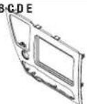
Interior view of a car dashboard with air conditioners and a digital display (no visible text or symbols)KIT COMPONENTS
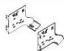
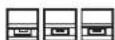
- A) Radio trim panel • B) Radio brackets • C) Pocket • D) (3) metal panel clips • E) (3) plastic panel clips
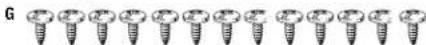
- F) (4) #8 x 3/8" Phillips truss-head screws • G) (13) #8 x 3/8" Phillips pan-head screws
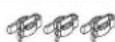
• H) (3) #4 x 3/8" Phillips truss-head screws • I) (2) #8 x 1/2" Phillips pan-head screws
A B C D E


WIRING & ANTENNA CONNECTIONS (sold separately)
Wiring Harness: • Please visit metraonline.com for options
Antenna Adapter: • 40-HD11
TOOLS REQUIRED
- Panel removal tool - Phillips screwdriver - 8mm socket wrench
Table of Contents
Dash Disassembly 2
Kit Preparation....3
Kit Assembly
- ISO DIN radio provision with pocket....3
CAUTION! Metra recommends disconnecting the negative battery terminal before beginning any installation, unless the vehicle manufacturer recommends against so. Please check with your local Dealership for more information. All accessories, switches, climate controls panels, and especially air bag indicator lights must be connected before reconnecting the battery or cycling the ignition. Also, do not remove the factory radio with the key in the on position, or the vehicle running. It would be best to remove the key from the ignition and then wait a few seconds before removing the factory radio.
Dash Disassembly
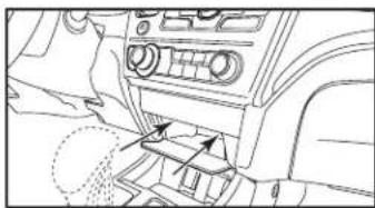
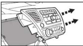
- Open the pocket door below the radio, remove (2) Phillips screws exposed, and then remove the pocket. (Figure A)
- Remove (2) Phillips screws from the bottom edge of the radio. (Figure B)
- Remove (2) 8mm screws facing up from inside the pocket cavity. (Figure C)
- Unsnap and remove the climate/radio panel assembly. (Figure D)
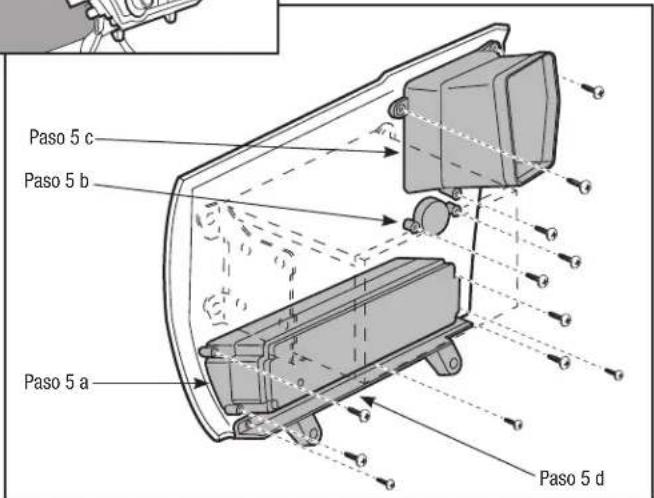
- Remove the components from the climate/radio panel to be reused in kit assembly. (Figure E)
a. Remove (4) screws from the climate control panel.
b. Remove (2) screws from the factory hazard button.
c. Remove (3) screws from the factory vent.
d. Remove (3) screws from the lower trim panel.
Continue to kit preparation
natural_image
Line drawing of a car interior showing dashboard and air vent (no text or symbols)(Figure A)

natural_image
Technical line drawing of a vehicle front bumper with mounting bracket (no text or symbols)(Figure B)

natural_image
Technical diagram of a mechanical assembly with no visible text or symbols(Figure C)
natural_image
Diagram of a car air conditioning unit with directional arrows indicating motion (no text or symbols)(Figure D)

text_image
Step 5 c Step 5 b Step 5 a Step 5 d(Figure E)
99-7882B
Kit Preparation Kit Assembly
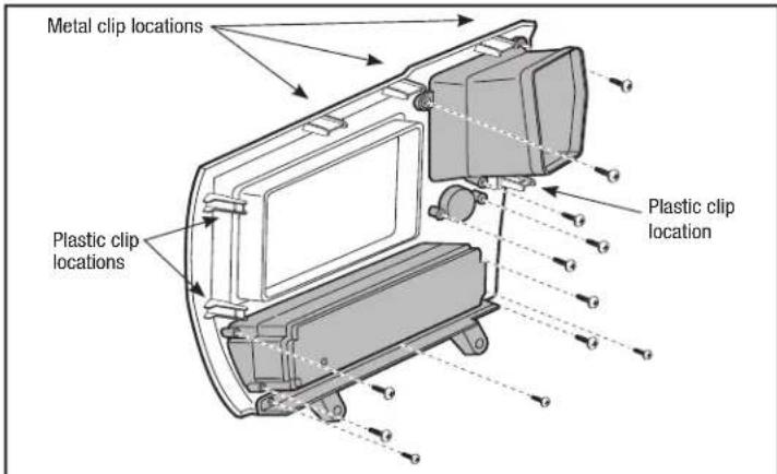
- Secure the factory components removed in dash disassembly to the radio panel. Except for the (3) screws to secure the lower trim panel, either the factory screws or the (9) #8 x 3/8" Phillips pan-head screws supplied with the kit may be used. For the lower trim panel use the (3) #4 x 3/8" Phillips truss-head screws supplied with the kit to secure it to the panel. (Figure A)
- Attach the (3) metal and (3) plastic panel clips to the radio panel. The factory metal clips may be used in place of the metal clips, but not the plastic clips. (Figure A)
Continue to kit assembly
text_image
Metal clip locations Plastic clip locations Plastic clip location(Figure A)
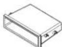
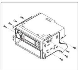
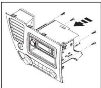
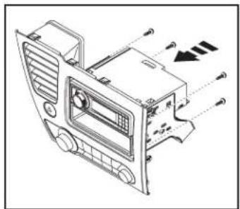
ISO DIN radio provision with pocket
- Secure the pocket to the radio brackets with the (4) #8 x 3/8" Phillips pan-head screws supplied with the kit. (Figure A)
- Remove the metal DIN sleeve and trim ring from the aftermarket radio.
- Slide the radio between the bracket/pocket assembly and secure it with the screws supplied with the radio. (Figure B)
- Secure the completed assembly to the radio trim panel with the (4) #8 X 3/8" Phillips truss-head screws supplied with the kit. (Figure C)
- Locate the factory wiring harness and antenna connector in the dash and complete all necessary connections to the radio. Metra recommends using the proper mating adapter from Metra and/or AXXESS. Re-connect the negative battery terminal and test the radio for proper operation.
- Reassemble the dash in reverse order of disassembly using the (2) #8 x 1/2" Phillips pan-head screws supplied with the kit for the lower radio mounts.
text_image
Technical diagram of an electronic device with labeled ports and internal components(Figure A)
natural_image
Technical line drawing of a car air conditioning unit with fan, vent, and door (no text or labels)(Figure B)
Installation instructions for part 99-7882B

IMPORTANT
If you are having difficulties with the installation of this product, please call our Tech Support line at 1-800-253-TECH. Before doing so, look over the instructions a second time, and make sure the installation was performed exactly as the instructions are stated. Please have the vehicle apart and ready to perform troubleshooting steps before calling.

KNOWLEDGE IS POWER
Enhance your installation and fabrication skills by enrolling in the most recognized and respected mobile electronics school in our industry. Log onto www.installerinstitute.com or call 800-354-6782 for more information and take steps toward a better tomorrow.

Metra recommends MECP certified technicians
Metra
U.S. PATENT # D728.554
Honda Civic 2013-2015 99-7882B
CARACTERÍSTICAS DEL KIT
natural_image
Interior view of a car dashboard with air conditioners and a digital display (no visible text or symbols)COMPONENTES DEL KIT
natural_image
Line drawing of a car interior showing dashboard and air vent (no text or symbols)(Figura A)

natural_image
Technical line drawing of a vehicle front bumper with mounting bracket (no text or symbols)(Figura B)
natural_image
Technical diagram of a mechanical assembly with no visible text or symbols(Figura C)

natural_image
Diagram of a car air conditioning unit with directional arrows indicating motion (no text or symbols)(Figura D)
text_image
Paso 5 c Paso 5 b Paso 5 a Paso 5 d(Figura E)
text_image
Technical diagram of a device with labeled components and directional arrows indicating assembly or movement.(Figura A)
natural_image
Technical line drawing of a car air conditioner unit with no visible text or symbols(Figura B)