AB-BP200X - Wall mount LG - Free user manual and instructions
Find the device manual for free AB-BP200X LG in PDF.

User questions about AB-BP200X LG
0 question about this device. Answer the ones you know or ask your own.
Ask a new question about this device
Download the instructions for your Wall mount in PDF format for free! Find your manual AB-BP200X - LG and take your electronic device back in hand. On this page are published all the documents necessary for the use of your device. AB-BP200X by LG.
USER MANUAL AB-BP200X LG
Please read the safety information carefully before using the product.
AB-BL200X
AD-BX200X
AB-BP200X
AD-BL200H
AD-BP200H
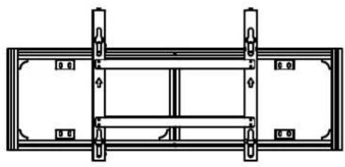
e-MultiVision Bracket AB-BL200X, AB-BP200X
natural_image
Technical line drawing of a structural frame with supports and mounting brackets (no text or symbols)E-MultiBoard Mounting Bracket - Landscape AB-BL200X
natural_image
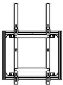
Pure structural diagram of a frame with vertical supports and mounting brackets (no text or symbols)E-MultiBoard Mounting Bracket - Portrait AB-BP200X

Accessories
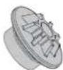
4 Guide Spacers

4 Guide Spacer Screws (M8 x 32 mm)
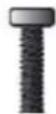
2 Bracket Screws (M8 x 100 mm)

2 Nuts
Owner's Manual
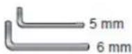
Wrench
e-MultiVision Stand AD-BX200X, AD-BL200H, AD-BP200H
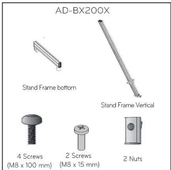
text_image
AD-BX200X Stand Frame bottom Stand Frame Vertical 4 Screws (M8 x 100 mm) 2 Screws (M8 x 15 mm) 2 Nuts
text_image
AD-BL200H, AD-BP200H Stand Frame Horizontal 4 Screws (M8 x 15 mm) 4 Nuts
Safety Precautions

- If you are a professional installer, please read this manual carefully before installing the product.
- After installing the product according to the manual, ensure that the user also reads the manual carefully.
After reading the manual, please keep it handy for future reference.

Warning
The product should be installed by a qualified professional specified by the retail store.
Installing the product without a qualified professional is dangerous and may cause injury.
When moving or replacing the product after installation, contact a qualified installer specified by the retail store.
Installation or movement of the product must be carried out by a skilled professional. If an unqualified person moves and installs the product, this may cause safety issues
Prior to installing the product, arrange the power cable and signal cable to prevent damage during the installation.
Damaged cables may result in a fire, electric shock or damage to the product.
To stand the product upright, two or more people are needed.
If you try to stand the product up alone, it may fall and cause an injury due to its weight.
The product should be installed where its weight can be supported.
If the product is installed on a weak surface, the product may fall and cause injury.
Do not hang on the product or impact the product.
The product may fall and cause injury.
Do not stand or hang on the product when upright.
The product may fall and cause injury.

Caution
Follow the instructions in the manual to install the product.
If you do not follow the instructions, the product may not be installed properly, causing serious injury or damage to the product.
Before installing the product, check whether the wall is strong enough to hold the product.
Installing the product on a wall that cannot hold its weight may cause safety issues.
Do not clean the product with wet towels, and do not use a heater or humidifier underneath the product.
Moisture permeating into the product, including through steam and heat, may result in a fire, electric shock or damage to the product.
Make sure that the power cord is removed from the outlet before installing the product.
Otherwise, it may cause an electric shock or a fire.
Place the product on a flat, hard floor.
Leaving the product on a carpet or cushioned surface may cause the product to fall and result in an injury.
To install or adjust the height of the product, two or more people are needed.
If you try to install or move the product alone, it may fall and cause injury or damage to the product.
Keep the product away from sprinklers, sprinkler sensors, high-tension wires and power sources. Do not install the product in a location where vibrations or shock impacts are likely to occur.
Wear working gloves when installing the product. Do not use bare hands.
Otherwise, it may cause injury.
Do not place the product on an unstable shelf or on a slanted or vibrating surface.
The product may fall or turn over and cause injury.

If the external surface has stains or fi ingerprints, gently wipe the stained area only.
Do not apply excessive force to remove the stain. This may cause scratches or discoloration.

Transportation method for panel protection
When moving or lifting the monitor, read the following to prevent the monitor from being scratched or damaged and for safe transportation regardless of its type and size.

CAUTION
- Avoid touching the screen at all times, as this may result in damage on the screen.
- It is recommended to move the monitor in the box or packing Cover that the monitor originally came in.
- Before moving or lifting the monitor, disconnect the power cord and all cables.
- Hold the top and bottom of the monitor frame firmly. Make sure not to hold the transparent part, speaker, or speaker grill area.

text_image
Diagram illustrating hand positioning and tool application steps for a monitor, with Chinese annotations indicating check and cross instructions.- When transporting the monitor, do not expose the monitor to jolts or excessive vibration.
- When transporting the monitor, keep the monitor upright, never turn the monitor on its side or tilt towards the left or right.
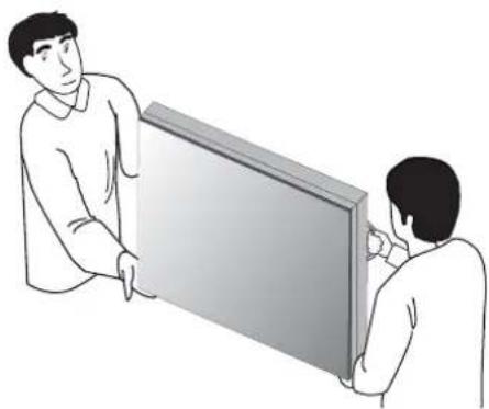
- When transporting the monitor by hand, hold the monitor as shown in the following illustration.
- When the product is carried upright, 2 persons carry by holding the bottom and top of the front, and when it is being put down, put down carefully for the panel not to be touched.
natural_image
Illustration of two people interacting with a large rectangular panel (no text or symbols visible)- When the product is carried laid down, 2 persons carry by holding the bottom of the back, and when it is being put down, put down carefully for the panel not to be touched.

natural_image
Two people handling a large rectangular object, possibly a tablet or case (no text or symbols visible)
Storage method for panel protection
text_image
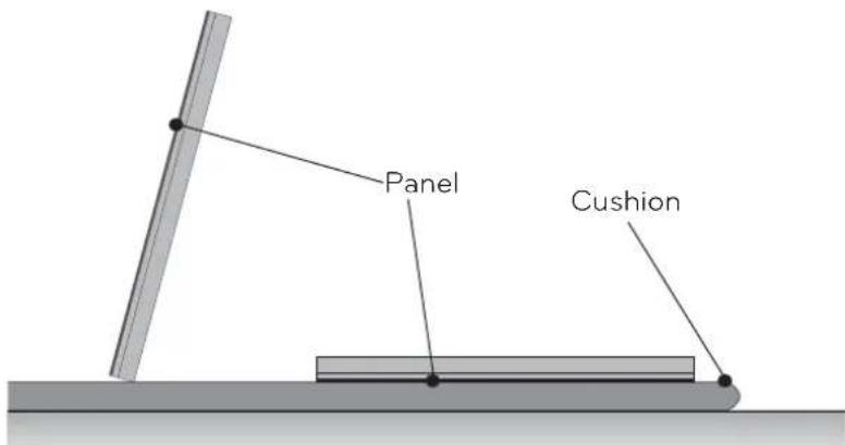
Panel CushionIf the product needs to be set upright, hold both sides of the product, and tilt backward carefully for the panel not to touch the floor. (The setting upright of the set is possible with the outer frame)
When laying down the product, lay a cushion on a flat floor, and put the product on it with the panel of the product facing down.

text_image
Panel PanelIf the product is tilted to the side of the panel, the bottom of the panel may be damaged.
If the product is tilted to the edge of the panel, the edge of the panel may be damaged.

NOTE
- Handle the product with care. The product may be damaged by shocks.

Before Installation
* Do not use this product for purposes other than to attach the monitor to the wall.
* Be careful when installing and using the bracket to prevent product damage and safety hazards.
* If the instructions in the manual are unclear, stop the installation and contact the service center.
If you are still having problems understanding the instructions after contacting the center, seek a professional to install the product.
When installing the bracket on a concrete wall or on any other walls capable of holding the strength specified in the manual, you may detach the standard gap bracket for stud wall mounting then follow the instructions for attaching the bracket to make the installation easier.
* Only install the bracket on vertical walls. Do not install the bracket on a wall inclined at an angle, exceeding the standard range or on the ceiling. LG Electronics is not liable for problems that occur due to the installation of the product on a slanted wall or on the ceiling.
* Check the accessories provided with the product before installing. LG Electronics is not liable for any damage to or loss of the accessories after the package has been opened.
* Make sure that the accessories are kept out of reach of children to prevent safety accidents, such as choking due to swallowing small parts.
* Make sure that the screws are fixed tightly.
Applying excessive force to screws may impair the performance or reduce the strength of the product, or cause it to become damaged.
* Make sure that the monitor to be installed does not exceed the specified tension load and that no external force is applied.
* In order to prevent accidents, take care when handling tools during installation of the product.
Philips screwdriver (manual or electric)/8 mm spanner/drill/level meter

How to Attach the Bracket (Stand Type)

natural_image
Technical line drawing of a multi-level metal frame structure with support columns (no text or symbols)1
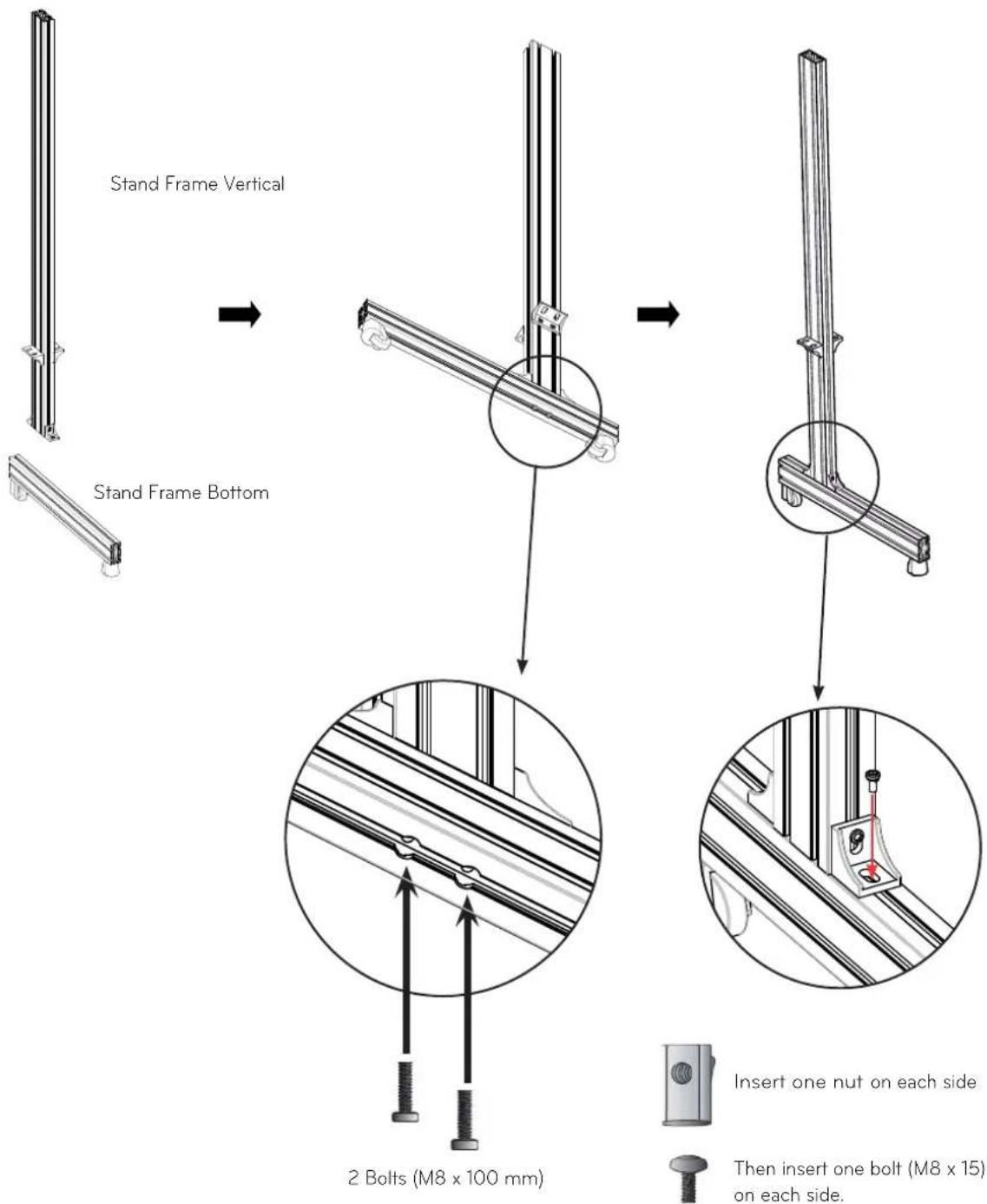
Attaching the Bottom Stand Frame and Vertical Stand Frame
Fix two bolts in the holes visible from the bottom as illustrated with the arrows. Insert a nut and then fix a M8 x 15 mm bolt.
text_image
Stand Frame Vertical Stand Frame Bottom 2 Bolts (M8 x 100 mm) Insert one nut on each side Then insert one bolt (M8 x 15) on each side.2
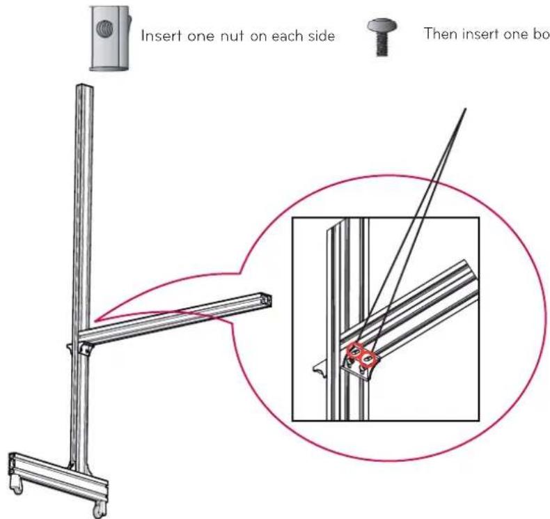
Attaching the Vertical Stand Frame and Horizontal Stand Frame
Place the horizontal stand frame on top of the angle guide of the vertical stand frame, insert a nut on each side, then fasten with two M8 x 15 mm bolts as illustrated with the arrow.
text_image
Insert one nut on each side Then insert one boFollow the same procedure to fix the nuts and bolts as required.
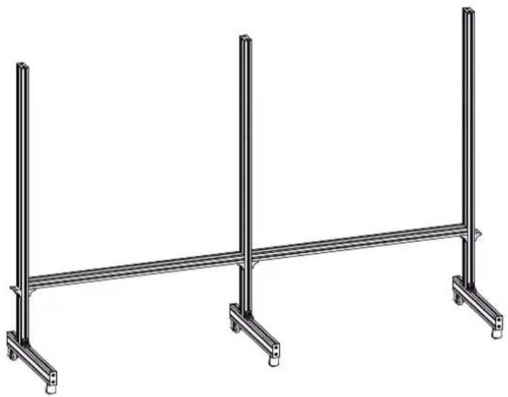
Example of Assembled Stand
natural_image
Technical line drawing of a structural support frame with vertical posts and horizontal beams (no text or symbols)3
Attaching the Horizontal or Vertical Bracket to the Stand
Place the horizontal or vertical bracket on the stand.
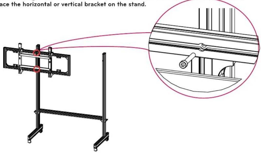
text_image
ace the horizontal or vertical bracket on the stand.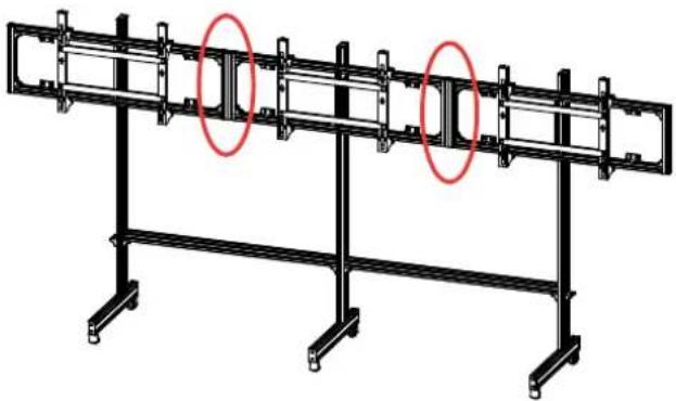
natural_image
Structural diagram of a multi-story frame with two red oval highlights on the left side (no text or symbols present)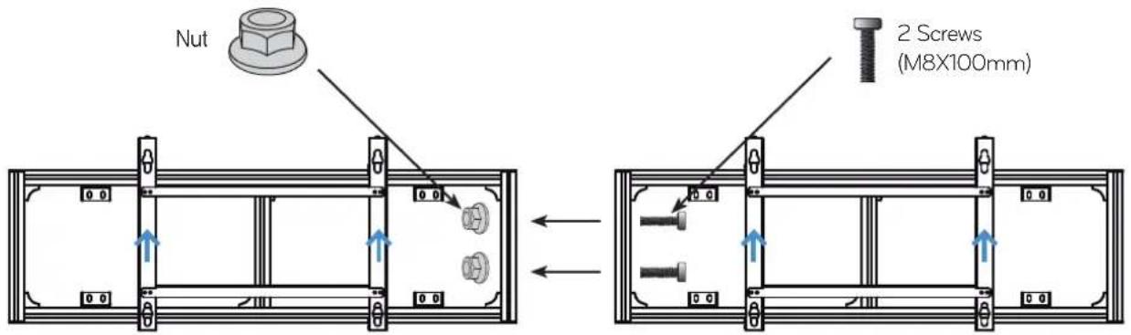
text_image
Nut 2 Screws (M8X100mm)
CAUTION
- Check the direction of the arrows shown in the figure above to avoid placing the bracket upside down.

How to Install (Wall mount type)
*
Verifying Where the Brackets Are Fixed
Refer to the following illustration to fix the brackets according to the type.
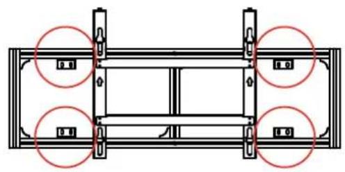
natural_image
Technical diagram of a structural frame with four circular annotations highlighting specific components (no text or symbols present)E-MultiBoard Wall Bracket-Landscape AB-BL200X
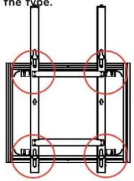
text_image
The type.E-MultiBoard Wall Bracket-Portrait AB-BP200X
Please refer to page 7.
text_image
Please refer to page 1.
text_image
Use a bolt that is capable of holding the weight of the product. (The combined weight of the set and the bracket is approx. 60 kg. We recommend using M8 bolts and nuts.)The bracket may be distorted depending on the flatness of the wall. Adjust the flatness of the bracket using the A bolts attached to it.

NOTE
This manual shows landscape installation. Follow the same procedure for portrait installation.

How to mount
1 Attaching the Guide Spacers
If the screws are not fully tightened when you fix the guide spacers, check the length of the screws and refer to the technical service manual.
4 Guide Spacer Fixing
Screws
(M8 × 32 mm)
Guide Spacer
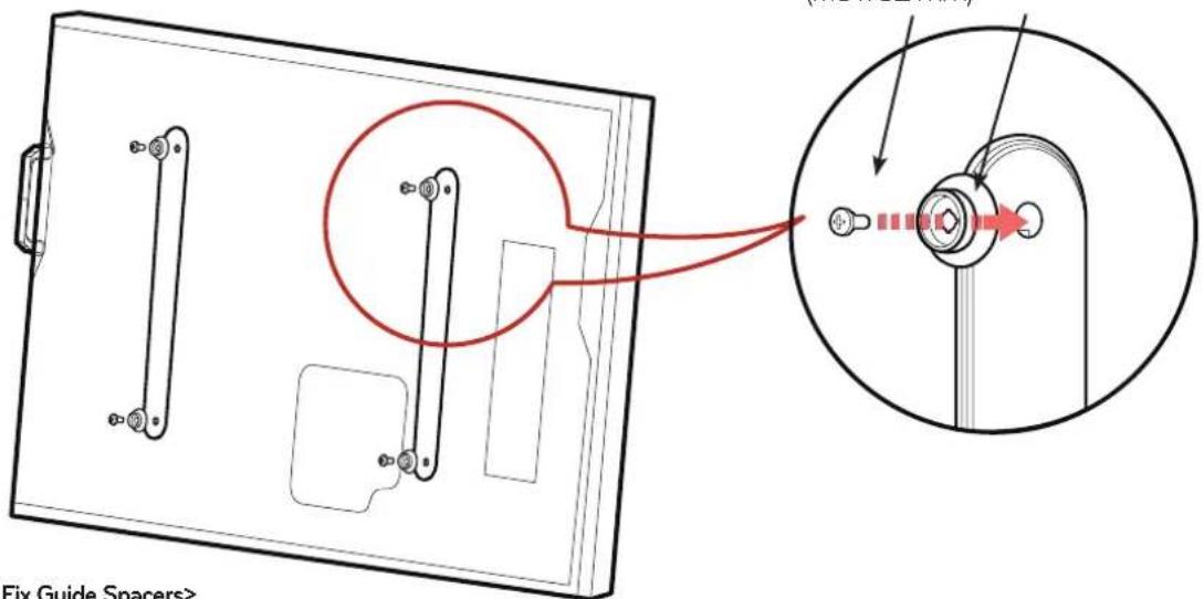
text_image
Fix Guide Spacers>Fix the guide spacers and the guide spacer fixing screws in the order shown in the picture. Lay the set down and fix the guide spacers to the set using the screws.
- Place the product on a table with its screen facing downward. Make sure that you place it on soft clothing or a cushion on the flat surface to protect the screen.
- Tighten the screw until the set, the guide spacer and the screw are joined together securely.
- Use a Philips driver (manual or electric) to tighten the screws.
2
Setting DIP Switch
- Please refer to the set's owner's manual.
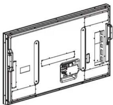
natural_image
Technical line drawing of a rectangular electronic device with internal components and mounting brackets (no text or symbols)
flowchart
graph TD
    A["Factory reset"] --> B["Monitor #1"]
    B --> C["Monitor #2"]
    C --> D["Monitor #3"]
    D --> E["Monitor #4"]
    style A fill:#f9f,stroke:#333
    style B fill:#f9f,stroke:#333
    style C fill:#f9f,stroke:#333
    style D fill:#f9f,stroke:#333
    style E fill:#f9f,stroke:#333
monitor #2
monitor #5
3
How to Attach the Product and Bracket
- Two or more people are needed to install the product.

natural_image
Technical line drawing of a mechanical assembly with an inset showing a close-up of a component (no text or symbols present)Place the product assembled with the guide spacers on the bracket wall, as illustrated with the arrow.
→ Make sure that the product is securely mounted to the bracket.
4
Cable Connection
- It is recommended to arrange cables running through the bracket before installing the set.
— For information on how to connect cables, please refer to the set's owner's manual.

text_image
RX TX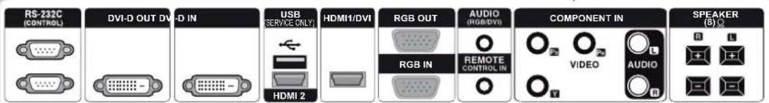
text_image
RS-232C (CONTROL) DVI-D OUT DV-D IN USB (SERVICE ONLY) HDMI 2 HDMI1/DVI RGB OUT AUDIO (RGB/DVI) RGB IN REMOTE CONTROL IN COMPONENT IN VIDEO AUDIO SPEAKER (8)
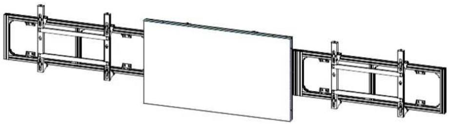
5
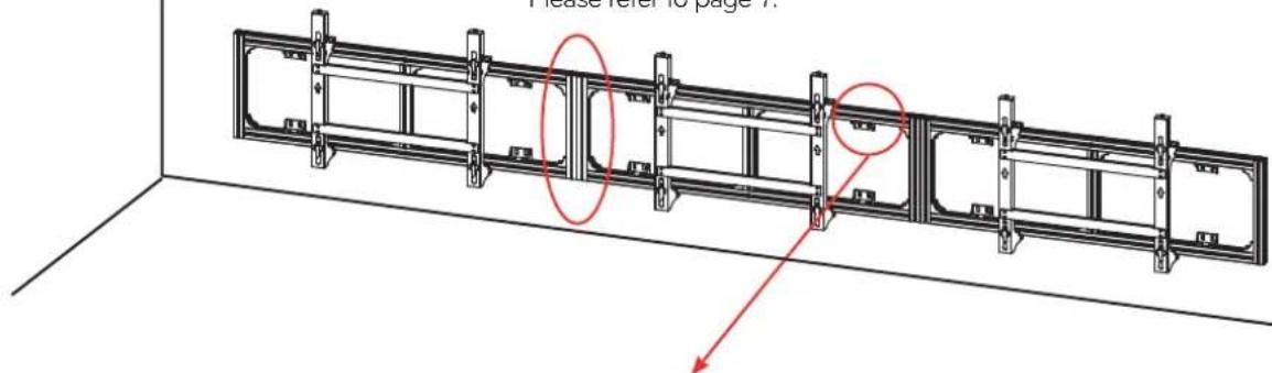
Set arrangement
- Mount set 2, then align it horizontally using the horizontal alignment screws.
- Fix the right and left sides securely using the right/left fixing screws.
natural_image
Technical line drawing of two mechanical components with brackets and mounting feet (no text or symbols)
text_image
Tighten the screws to fix the left and right slides.

NOTE
This manual shows landscape installation. Follow the same procedure for portrait installation.
- When mounting set 3, push bracket 3 to the right end to ensure there is enough space for set 2.
- Adjust the height using the horizontal alignment screws so that set 3 and set 2 are at the same height.
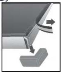
- Remove the module-protecting Cover on sets 2 and 3.

natural_image
Diagram of a mechanical assembly with two components and directional arrows indicating motion (no text or symbols)Remove the module-protecting Cover.
(The protective Cover is attached on all four sides; at this point, only remove the Cover on the sides where the sets meet.)
natural_image
Pure mechanical diagram showing a bracket with arrows indicating motion or force (no text or symbols)- Push set 3 toward set 2, then fasten the right and left sides securely using the right/left fixing screws. Similarly, push set 1 toward set 2, then fasten the sides using the left/right fixing screws.
(Caution: Push the sets gently and slowly to avoid damage due to a collision.)
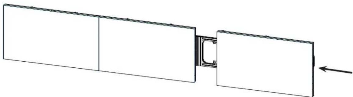
natural_image
Diagram showing a rectangular panel connected to a vertical panel with a curved cutout, and an arrow indicating direction (no text or symbols present)- Arrange the sets in a perfectly straight line using fixers so that sets do not stick out at the front or back. (It is not necessary to use all the fixers.)
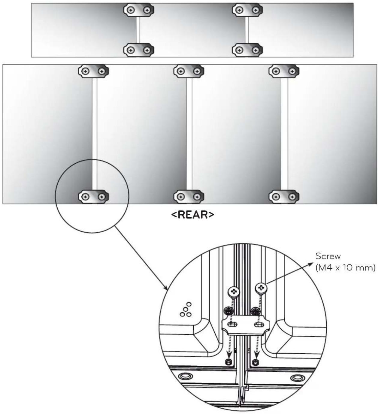
text_image
When you fix the screws, make sure that no set sticks out at the front or back. 8. Finally, remove all the module-protecting Cover on the outside of the sets.


| Model Name | AB-BL200X | AB-BP200X | AD-BX200X | AD-BL200H | AD-BP200H |
| Width (mm) | 1426 1110 1900 | 1540 960 | |||
| Height (mm) | 210 210 210 | 210 210 | |||
| Depth (mm) | 648 870 340 | 170 170 | |||
| Weight (kg) | 16.5 | 17.3 | 9.2 | 4.8 | 3 |
The model name and serial number are located on the back and side of the product. Please make a note of these below.
Model Name
Serial Number