
PSW400BG - Wall mount LG - Free user manual and instructions
Find the device manual for free PSW400BG LG in PDF.


User questions about PSW400BG LG
0 question about this device. Answer the ones you know or ask your own.
Ask a new question about this device
Download the instructions for your Wall mount in PDF format for free! Find your manual PSW400BG - LG and take your electronic device back in hand. On this page are published all the documents necessary for the use of your device. PSW400BG by LG.
USER MANUAL PSW400BG LG
Wall Mounting Bracket
Please read this manual carefully before installation and retain it for future reference.
PSW400B
PSW400BG
PSW600B
PSW600BG
* 1 Year Warranty
If material or workmanship proves defective under normal use, during the warranty period, please contact the retailer where you purchased it. This warranty is good only to the original purchaser of the product and effective only in the local area.
text_image
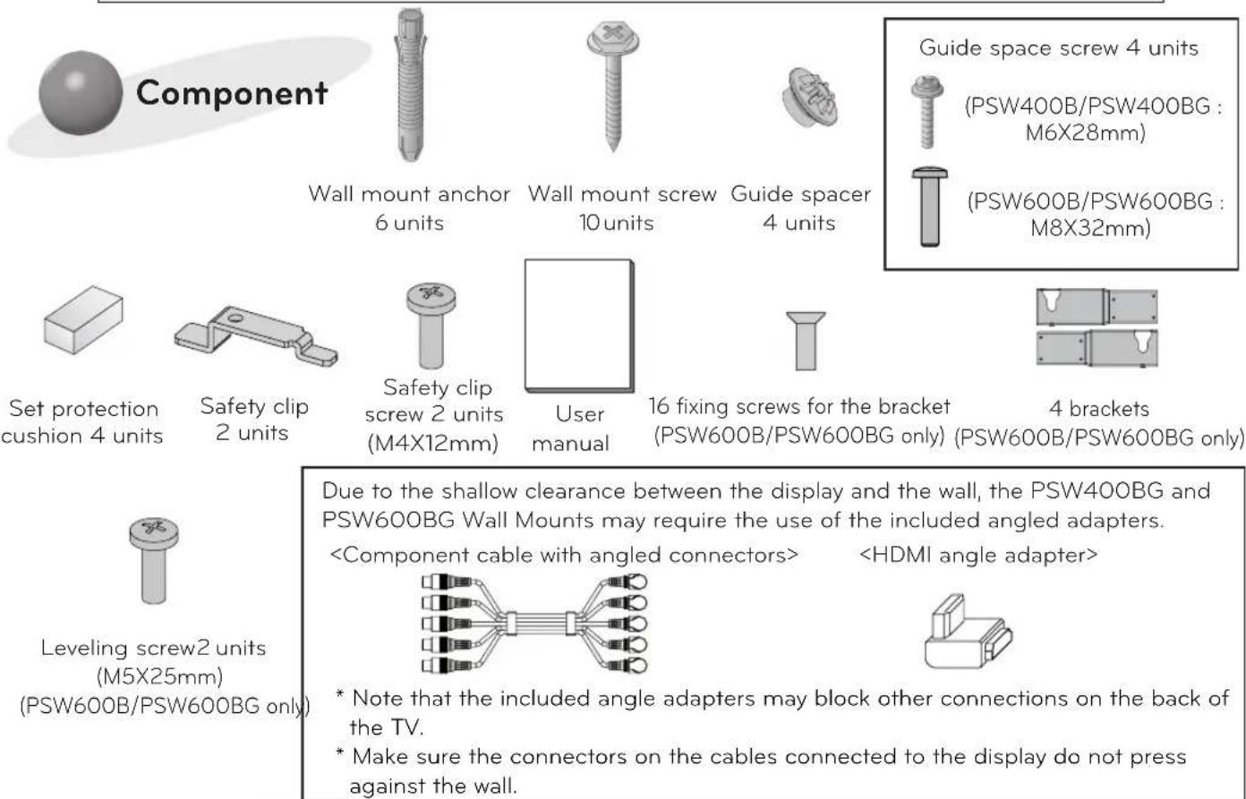
Component Wall mount anchor 6 units Wall mount screw 10 units Guide spacer 4 units Guide space screw 4 units (PSW400B/PSW400BG : M6X28mm) (PSW600B/PSW600BG : M8X32mm) Set protection cushion 4 units Safety clip 2 units Safety clip screw 2 units (M4X12mm) User manual 16 fixing screws for the bracket (PSW600B/PSW600BG only) (PSW600B/PSW600BG only) 4 brackets Leveling screw2 units (M5X25mm) (PSW600B/PSW600BG only) Due to the shallow clearance between the display and the wall, the PSW400BG and PSW600BG Wall Mounts may require the use of the included angled adapters.
IMPORTANT SAFETY INSTRUCTIONS
Read these instructions.
Keep these instructions.
Heed all warnings.
Follow all instructions.

Warning
This wall mount should be installed by a trained and experienced installer designated by the retailer.
Having the product installed by a non-specialized installer is very dangerous and can cause damage or injury.
Use a trained and experienced installer to move or replace the wall mount, if needed.
Installation requires special techniques and moving or installing the product on your own can cause serious safety issues.
When installing the wall mount, never hang the power or signal cable on the rear side the TV.
The cord can be damaged and cause a fire, an electric shock or damage to the product.
Do not install the product where the weight cannot be supported.
If the strength of the location where the wall mount is installed is not strong enough, it can fall off and cause an injury.
After installing the wall mount, do not hang on the product and prevent severe impact to the product.
The product can fall off and cause injury.

Caution
Install the product according to the directions in the user manual. If the product is not installed based on the directions in the user manual, it can cause a serious injury or damage to the product.
During the installation, check the type of wall material and use the sealed anchor and screw if the conditions comply.
If you do not use the designated anchor or screw, the mount may not be able to withstand the weight of the product and cause a safety issue.
Do not wipe the product with a wet towel and do not use any heater or humidifier below where the product is installed.
If water flows into the product or if moisture and heat are applied to the product, it can cause a fire, an electric shock or problem to the product.
Unplug the power cord from the power outlet before installing the product.
If you install the product with the power cord plugged, it can cause an electric shock or a fire.
Do not allow the video connectors connected to the display to press against the wall. Use the included right-angle adapters if needed.
Only use attachments/accessories specified by the manufacturer.
When installing the product or adjusting the height of the product after installing, always do so with 2 people.
Working alone can cause the product to fall off and result in injury or damage to the product.
When drilling holes in the wall, always use a drill bit and drill of designated diameter. Also follow the designated directions for the depth of the hole.
If the product is installed without following the designated method, the product may be unstable and cause a safety issue.
Donot install the product near any object that may cause vibration.
Do not install the product near any high voltage power cable or power source.
Do not install the product with bare hands. Always wear proper work gloves.
It can cause an injury.
Before installation
* Do not use the product for purposes other than mounting a display on the wall.
* When installing/using the wall mount, be cautious of product damage and avoid accidents.
* If you have not fully read and understood the installation manual, do not install the product and contact the dealer to have a specialized installer install the product for you.
* Even if you are not a specialized installer, it is advantageous to have experience in mechanical or construction field in completely understanding this manual and installing the product.
* This product is designed to be mounted to walls that use standard intervals between the studs.
* Install the screw to attach the wall mount so that it can be assembled at the center from both ends of the studs.
Use of stud finder, a separate device, is recommended.
* Install the product only on a vertical wall.
The manufacturer is not responsible for issue from installing the product on severely wall or on the ceiling.
* Keep the included accessories out of reach of babies or children as it can cause safety issues including suffocation from swallowing the parts.
* Make sure screws are tight against the wall, but do not overtighten.
* Be careful not to install a TV that exceeds the weight restrictions of the wall mount.
* Be careful with the tools used during installation to prevent accidents or damage.
Installation method
- Tools you will need : Phillips head "+" driver(Manual or motorized) ∅4mm drill bit for wood or steel / Level / Stud finder / Drill. You may also need an 8mm socket wrench or an 8mm drill bit for concrete.
- Installation method is described based on the PSW400 model. The actual product may differ from the picture.

Fixating the mounting bracket on the TV
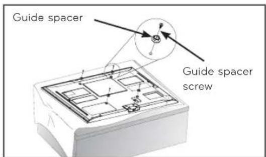
- If the screw will not fully tighten when using a guide spacer, recheck the assembly depth of the screw and refer to the technical service manual.
text_image
Guide spacer Guide spacer screw- Check to see if the display has screws installed into the mounting holes. If so, remove those.
- Assemble the guide spacer and the guide spacer screw in order as shown in the picture.
Lay the set down and secure the guide spacer and the set using the screws. - Put the product on the table placing the screen face down.
When doing this, it is highly recommended to place a floor cushion or soft clothes on the flat table before putting the product on it to avoid any damage of the screen surface. - Tighten the screw until the set, guide spacer and the screw are fully pressing against one another.
- Use the "+" driver (Manual or motorized) when tightening the screw.
2
How to attach to masonry walls
- Use the anchors for wall material of concrete, light concrete, strong natural stone, soft natural stone masonry brick and hallow block that do not crack.
Please follow the below direction.
- Check the material of the wall and the thickness of the finishing.
- When installing the product on the wooden wall, refer to page 5.
- When installing the product on wall material not designated, install the product so that each fixated location can withstand the pull out load of 70kgf (686N) and shear load of 10kgf (980N) or above.
text_image
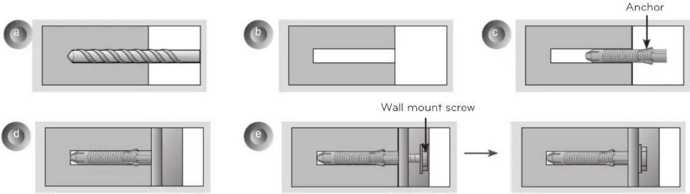
Anchor Wall mount screw- Use the ∅8mm drill bit for concrete and hammer (Impact) drill.
a. Use a drill bit ∅8mm to drill a hole for the anchor location within a depth of 80mm \~ 100mm
b. Clean the drilled hole.
c. Insert the sealed anchor to the hole. (When inserting the anchor, use a hammer.)
d. Set the wall mount on the wall by aligning to the location of the hole. and, set the angle adjusting part to face upward.
e. Align the wall mount bolt to the hole and tighten it. At this time, the bolt must be tightened with torque of 45kgf/cm or above.
3
How to install the wall mount
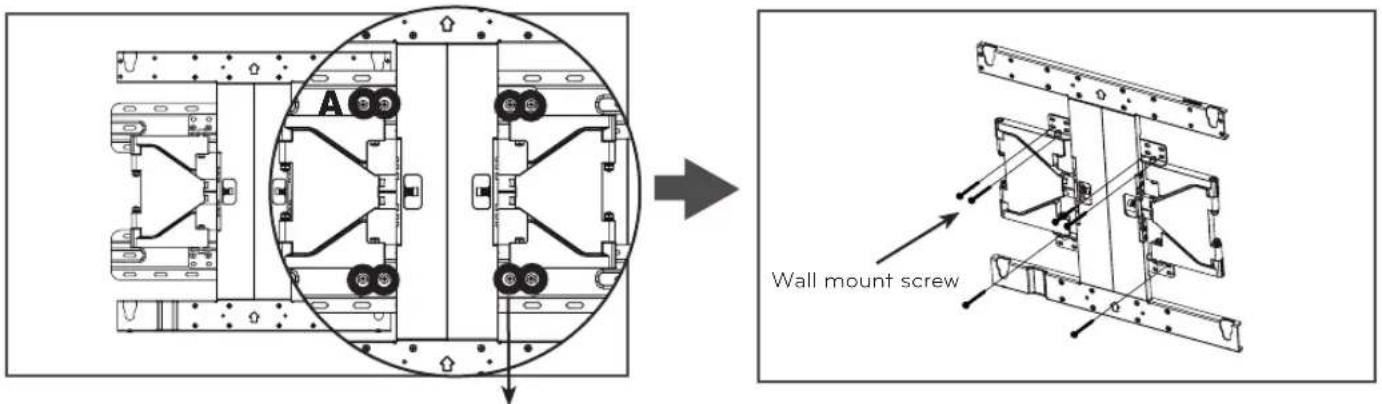
→ When you separate the 8 screws on the wall mount connected to the wall bracket for use with a wooden wall, it is much easier to install the product.
text_image
A C Wall mount screwSeparate the wall mount screw.
→ When installing the product on a masonry wall, turn the 8 screws on the A part counterclockwise to separate the screw and bracket.
→ After aligning the wall bracket to the location to install, mark the part to screw on the wall and then remove the wall bracket.
→ Refer to page 3 to attach the wall bracket.
→ Use a level to check whether the wall mount is level.
→ If the screw cannot be assembled in the designated location inevitably, it can be assembled by rearranging to the closest location. But, do not change 2 or more locations from the designated spot.
→ Assemble the wall mount screw on 2 left and 2 right locations on the top and 1 left and 1 right location on the bottom part.
→ At this time, use a "+" driver (Manual or motorized) or 8mm wrench to tighten the screw so that the wall, wall bracket and screw are completely pressed against one another.
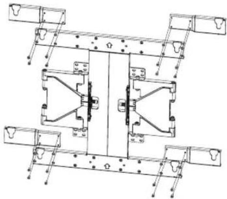
* PSW600B / PSW600BG models only.
natural_image
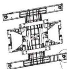
Technical line drawing of a mechanical assembly with mounting brackets and mounting holes (no text or symbols)- For PSW600B / PSW600BG models, remove the height adjusting screws before installing the wall mount, and then assemble the extended bracket. Use the removed screws to install the extended bracket.
- Before installing the wall mount, secure the 4 bracket fixing screws on the upper left and right sides respectively and 4 on the lower left and right sides respectively.
(Use a hand or electric cross-head screwdriver.)
- A fastening adhesive is provided to make sure that the bracket fixing screws are fully inserted.
text_image
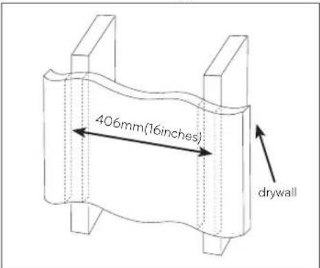
406mm(16inches) drywalla. Locate and mark the centers of the wall studs using a stud finder.
text_image
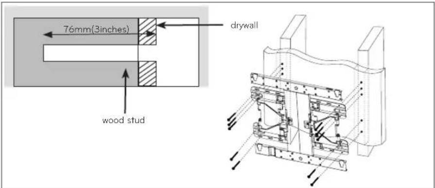
76mm(3inches) drywall wood studb. After aligning the wall bracket on the wall where the center of the wood stud is marked, mark the location of the screws and then remove the wall bracket.
c. Use a level to make sure your screw marks are level.
d. Use the 4mm drill bit for wood to drill holes with the depth of 76mm or above where the wall mount screw location is marked on the wall.
e. Clean the drilled hole.
f. Tighten the wall mount screws for the wall bracket on the drilled hole.
→ At this time, tighten the screw so that the wall, wall bracket and the wall mount screw are pressed against one another. (Drywall can be damaged when tightened with excessive force, please be careful.)
→ When tightening the screw use the "+" driver (Manual or motorized) or 8mm wrench.
4 How to assemble the wall mount support and display
- Always install the display with 2 or more people.
text_image
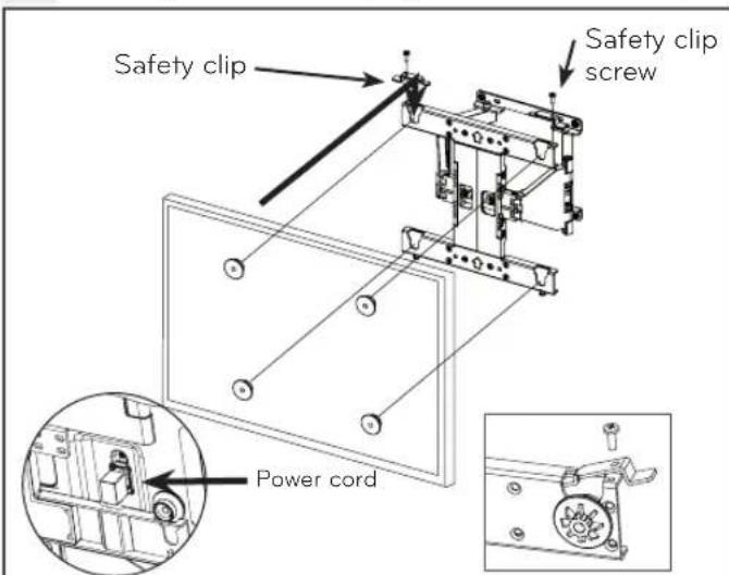
Safety clip Safety clip screw Power cord* For PSW400B / PSW400BG* Insert the safety clip into the wall models, connect the power cord mount bracket and secure them to the set first. with the fixing screw.
-
Set the display with the guide spacer assembled on the wall mount bracket on the wall in arrow direction. At this time, align the bottom assembly part and lift the set up lightly to align the top part. (For PSW400B / PSW400BG models, connect the power cord first when installing the set on the wall mount.)
-
When adjusting the location, assemble the provide safety clip as shown in the picture to prevent the product from moving. Tighten the safety clip screw completely. If the safety clip is not tightened as shown in the picture, the product can fall off.
→ Pull on the bottom of the set to make sure the display is secure.
→The distance between the installed TV and the wall will be 17.8 mm. (If you install the wood fixing bracket, the distance will be 23.8 mm) Make sure to keep a certain level of distance from the wall so that excessive force is not applied on the cable or accessory.
→ When you push the product with excessive force, the product can be damaged.
natural_image
Technical line drawing of a mechanical assembly with no visible text or symbols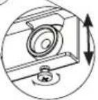
natural_image
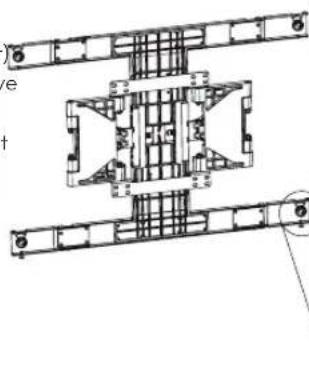
Architectural floor plan diagram showing structural layout with numbered components (no text or labels)Use the supplied two leveling screws
(M5 x 25 mm) to adjust the tilt of the wall mount.
6
Cable arrangement and set protection cushion
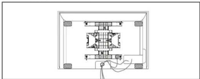
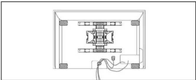
- Arrange the cables as shown in the picture. Use some type of cable banding device to hold all the cables together.
- Attach the set protection cushion to mitigate the impact between the wall and the set when adjusting the angle. Attach the set protection cushion as shown in the picture.
natural_image
Technical line drawing of a mechanical assembly with mounting holes and internal components (no text or symbols)
natural_image
Technical line drawing of a mechanical assembly with no visible text or symbols
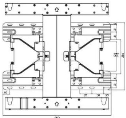
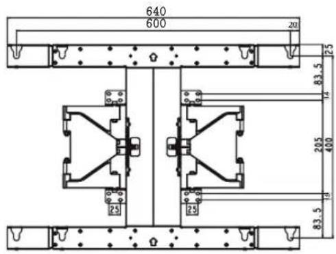
Product specification
| Model Name | PSW400BPSW400BG | PSW600BPSW600BG |
| Width (mm) | 440 640 | |
| Height (mm) | 450 450 | |
| Depth (mm) | 14 14 | |
| Weight (kg) | 3.4 4.1 | |
| Wall Mount VESASpecification | 400 x 400 600 x 400 | |
| Max Load Capacity (kg) | 50 50 | |
| Model Name | PSW400BPSW400BG | PSW600BPSW600BG |
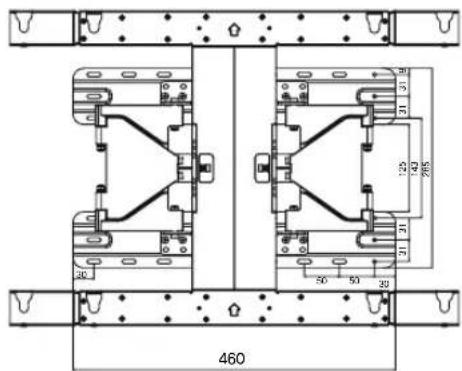
| Width (mm) | 460 640 | |
| Height (mm) | 450 450 | |
| Depth (mm) | 20 20 | |
| Weight (kg) | 5.6 6.3 | |
| Wall Mount VESASpecification | 400 x 400 600 x 400 | |
| Max Load Capacity (kg) | 50 50 | |
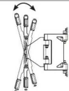
natural_image
Mechanical assembly diagram showing a rotating lever mechanism with multiple arms and a central pivot (no text or symbols)-15^ +15^ ± 2^
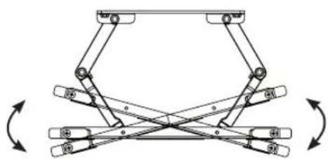
natural_image
Mechanical linkage diagram showing bidirectional motion between two components (no text or symbols)-15^ +15^ ± 2^
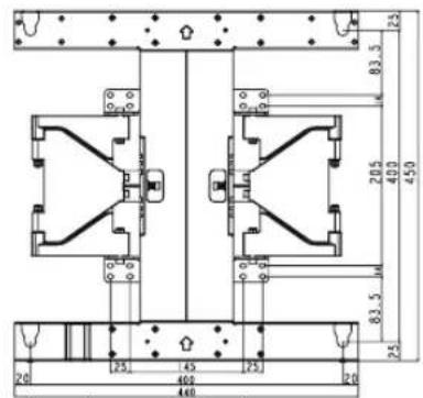
text_image
20 125 400 460 275 20 83.5 20.5 40.0 45.0 83.5 25 460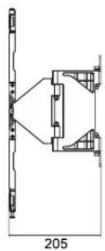
natural_image
Technical line drawing of a mechanical assembly with dimension标注 (no text or symbols)
text_image
30 450 50 50 30 120 250 31 31 31 31 450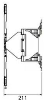
natural_image
Technical line drawing of a mechanical assembly with dimension标注 (no text or symbols)
text_image
640 600 20 25 83.5 14 205 400 83.5 25 25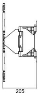
natural_image
Technical line drawing of a mechanical assembly with no visible text or symbols
text_image
460 50 51 30 52 59/2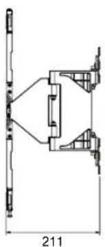
natural_image
Technical line drawing of a mechanical assembly with dimension标注 (no text or symbols)

LG
Life's Good
The model and serial number of the product is located on the back or one side of the product. Record it below should you ever need service.
MODEL ____
SERIAL
Supported Displays:
(Consult the retailer for detail list of models.)
PSW400B/PSW400BG Supports:
- 42PJ*/50PJ*/50PK*
PSW600B/PSW600BG Supports:
- 60PK*