Windham - Lighting Kichler - Free user manual and instructions
Find the device manual for free Windham Kichler in PDF.

User questions about Windham Kichler
0 question about this device. Answer the ones you know or ask your own.
Ask a new question about this device
Download the instructions for your Lighting in PDF format for free! Find your manual Windham - Kichler and take your electronic device back in hand. On this page are published all the documents necessary for the use of your device. Windham by Kichler.
USER MANUAL Windham Kichler
text_image
KICHLER LIGHTING Kichler Lighting 7711 East Pleasant Valley Road P.O. Box 318010 Cleveland, Ohio 44191-8010 Customer Service 868.558.5/06 8:30 AM to 5:00 PM EST, Monday - Friday
text_image
Windham® A Kichler® Select® ceiling fan Instruction Manual KICHLER LIGHTING C US LISTED for Deep Location1. SAFETY RULES
- To reduce the risk of electric shock, insure electricity has been turned off at the circuit breaker or fuse box before beginning.
- All wiring must be in accordance with the National Electrical Code and local electrical codes. Electrical installation should be performed by a qualified licensed electrician.
- WARNING: Suitable for use with solid-state speed controls.
- WARNING: To reduce the risk of personal injury, use only the two steel screws (and lock washers) provided with the outlet box for mounting to the outlet box. Most outlet boxes commonly used for the support of lighting fixtures are not acceptable for fan support and may need to be replaced, consult a qualified electrician if in doubt.
WARNING
TO REDUCE THE RISK OF FIRE, ELECTRIC SHOCK OR PERSONAL INJURY, MOUNT FAN TO OUTLET BOX MARKED "ACCEPTABLE FOR FAN SUPPORT".
- The outlet box and support structure must be securely mounted and capable of reliably supporting a minimum of 50 pounds. Use only CUL Listed outlet boxes marked "FOR FAN SUPPORT".
- The fan must be mounted with a minimum of 7 feet clearance from the trailing edge of the blades to the floor.
-
To operate the reverse function on this fan, press the reverse button while the fan is running.
-
WARNING: Use only with light kit marked "Suitable for Use in Damp Locations".
- Avoid placing objects in the path of the blades.
- To avoid personal injury or damage to the fan and other items, be cautious when working around or cleaning the fan.
- Do not use water or detergents when cleaning the fan or fan blades. A dry dust cloth or lightly dampened cloth will be suitable for most cleaning.
- After marking electrical connections, spliced conductors should be turned upward and pushed carefully up into outlet box. The wires should be spread apart with the grounded conductor and the equipment-grounding conductor on one side of the outlet box.
- Electrical diagrams are reference only. Light kits that are not packed with the fan must be CUL Listed and marked suitable for use with the model fan you are installing. Switches must be CUL General Use Switches. Refer to the Instructions packaged with the light kits and switches for proper assembly.
WARNING
TO REDUCE THE RISK OF PERSONAL INJURY, DO NOT BEND THE BLADE BRACKETS (ALSO REFERRED TO AS FLANGES) DURING ASSEMBLY OR AFTER INSTALLATION. DO NOT INSERT OBJECTS IN THE PATH OF THE BLADES.
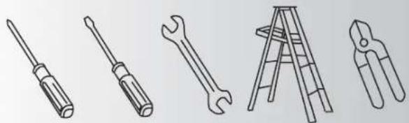
2. TOOLS AND MATERIALS REQUIRED
- Philips screw driver
- Blade screw driver
- 11 mm wrench
- Step ladder
- Wire cutters
natural_image
Line drawings of five different tools: screwdriver, wrench, ladder, and pliers (no text or symbols)3. PACKAGE CONTENTS
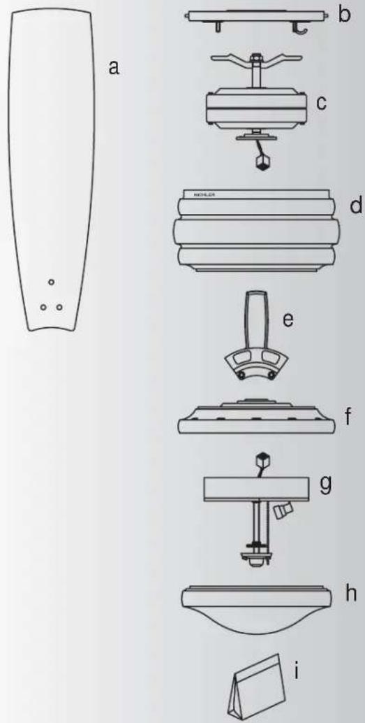
Unpack your fan and check the contents. You should have the following items:
a. Fan blades (5)
b. Mounting plate
c. Fan motor assembly
d. Motor housing
e. Set of blades brackets (5)
f. Mounting plate
g. Light kit
h. Glass shade
i. Part bag contents
1) Mounting hardware :
wood screws (2), flat washers (2),
star washers (2), wire nuts (3)
2) Blade attachment hardware: screws (17), washers (17), rubber washers (17)
3) Blade brackets hardware: screws (10)
4) Safety cable hardware: wood screw, lock washer, flat washer
5) Close mount hardware: screw with lock washers (3)
6) Pull chain and fobs (2)
7) Balance Kit
text_image
a b c d e f g h i
text_image
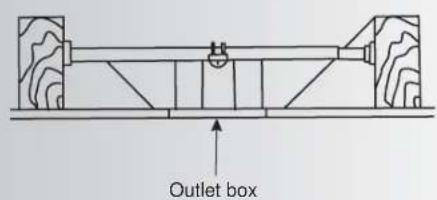
Outlet boxFig. 1

natural_image
Pure mechanical diagram showing a cylindrical component mounted on a base with a curved pipe and directional arrow (no text or symbols)
natural_image
Technical diagram of a mechanical assembly with no visible text or symbolsFig. 2
text_image
Outlet boxFig. 3
4. MOUNTING OPTIONS
If there isn't an existing UL (CUL for Canadian Installation) listed mounting box, then read the following instructions. Disconnect the power by removing fuses or turning off circuit breakers
Secure the outlet box directly to the building structure. Use appropriate fasteners and building materials. The outlet box and its support must be able to fully support the moving weight of the fan (at least 50 lbs). Do not use plastic outlet boxes.
Figures 1 and 2 are examples of different ways to mount the outlet box.
NOTE: You may need a longer downrod to maintain proper blade clearance when installing on a steep, sloped ceiling. (Fig. 3)
To hang your fan where there is an existing fixture but no ceiling joist, you may need an installation hanger bar as shown in Fig 3.
5. HANGING THE FAN
REMEMBER to turn off the power. Follow the steps below to hang your fan properly:
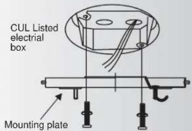
Step 1. Attach the mounting plate to the outlet box with two screws and washers provided with the outlet box. Make sure the mounting plate is tight and secured. (Fig. 4)
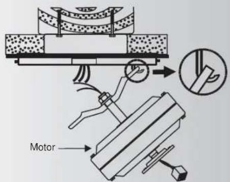
Step 2. Lift fan into position by hanging the motor assembly onto the hook from the ceiling mounting plate allowing it to hang freely. (Fig. 5)
text_image
CUL Listed electrial box Mounting plateFig. 4
text_image
MotorFig. 5
6. INSTALLATION OF SAFETY SUPPORT (for Canadian Installation ONLY)
An additional safety support is provided to prevent the fan from falling fan). Place the end of cable through the loop of ceiling support cable. Pull as much cable through loop as possible. Feed end of cable into clamp hole and firmly tighten screw (Fig. 6). Cut off excess safety cable. Secure the safety cable to the ceiling joist with screw and washer.

text_image
Outlet box Attach safety cable to ceiling joist with screw and washerFig. 6
text_image
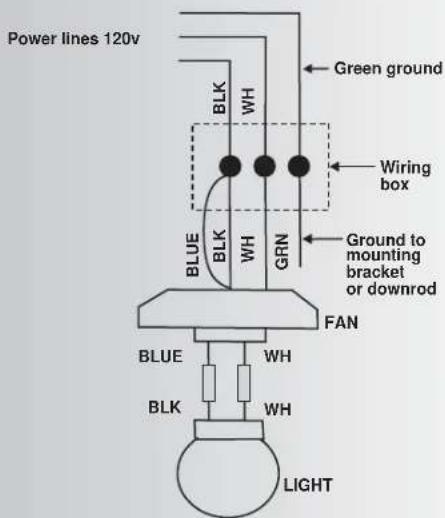
Power lines 120v Green ground BLK WH Wiring box BLUE BLK WH GRN Ground to mounting bracket or downrod FAN BLUE WH BLK WH LIGHTFig. 7

text_image
Power lines 120v Green ground Wiring box Ground to mounting bracket or downrod FAN BLUE BLK WH BLK WH BLUE BLK LIGHTFig. 8
text_image
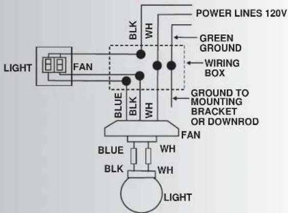
POWER LINES 120V GREEN GROUND WIRING BOX GROUND TO MOUNTING BRACKET OR DOWNROD FAN BLUE BLK WH BLK WH BLUE BLK WH LIGHT WH WH LIGHTFig. 9
7. MAKE THE ELECTRIC CONNECTIONS
Remember to disconnect the power.
Follow the steps below to connect the fan to your household wiring. Use the wire connecting nuts supplied with your fan.
Secure the connectors with electrical tape.
Make sure there are no loose strands or connections.
Step 1 Connect the fan supply (black) wire and light supply (blue) wire to the black household supply wire as shown in Figure 7.
Step 2. Connect the neutral fan (white) wire to the white neutral household wire.
Step 3 Connect the fan ground wire (green) to the household ground wire.
Step 4 After connecting the wires, spread them apart so that the green and white wires are on one side of the outlet box and the black and the blue wires are on the other side.
Step 5 Turn the connecting nuts upward and push the wiring into the outlet box.
Figures 8 and 9 illustrate the wiring connections for optional wall control (The wire color out of wall control may vary, see wall control's installation manual for correct wire connections.)
WARNING: TO REDUCE THE RISK OF FIRE, ELECTRIC SHOCK, OR OTHER PERSONAL INJURY. MOUNT FAN ONLY ON AN OUTLET BOX OR SUPPORTING SYSTEM MARKED ACCEPTABLE FOR FAN SUPPORT.
8. FINISHING THE INSTALLATION
Step 1. Move fan into position over the four mounting studs and secure with the provided washers and nuts. (Fig. 10)
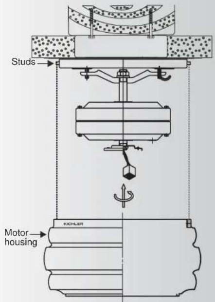
Step 2. Raise the motor housing up against the mounting plate, the four supports inside the housing should be placed against the four studs on mounting plate, twist the housing clockwise until snug. (Fig. 11)

text_image
Screws Washers NutsFig. 10
text_image
Studs Motor housing KICHLERFig. 11

text_image
KICHLER Screws Washers Rubber washers Blade Screws Blades bracketFig. 12
text_image
KICHLER Mounting ring Mounting plate ScrewsFig. 13
9. ATTACHING THE FAN BLADES
Step 1 Attach the blade to the blade bracket using the screws, washers and rubber washers as shown in Figure 12. Start screw into bracket. Repeat for the two remaining screws.
Step 2 Make sure the blade is straight and tighten each screw.
Step 3 Fasten blade assembly to motor using "Pre-Installed" mounting screws in the blade bracket.
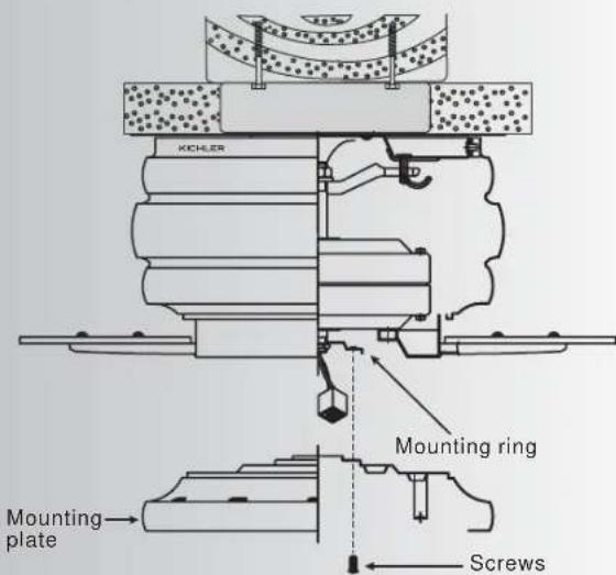
10. INSTALLING THE MOUNTING PLATE
- Remove 1 of the 3 screws from the mounting ring and loosen the other 2 screws. (Do not remove)
- Place the key holes on the mounting plate over the 2 screws previously loosened from the mounting ring, turn mounting plate until it locks in place at the narrow section of the key holes. Secure by tightening the 2 screws previously loosened and the one previously removed. (Fig. 13)
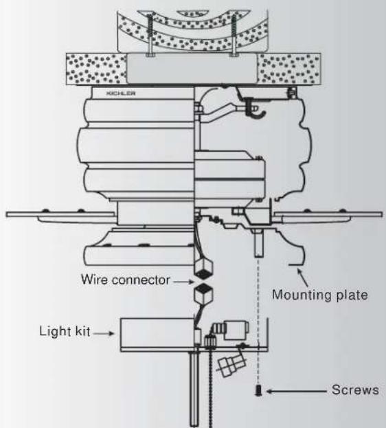
11. INSTALLING THE LIGHT KIT
NOTE: Before starting installation, disconnect the power by turning off the circuit breaker or removing the fuse at fuse box. Turning power off using the fan switch is not sufficient to prevent electric shock.
- While holding the light kit under your fan, snap together the wire connection plugs.
- Carefully push all wires back into the mounting plate, then install the light kit onto the mounting plate with 3 screws provided. Be sure to tighten all screws. (Fig. 14)
text_image
XICHLER Wire connector Mounting plate Light kit ScrewsFig. 14
12. NSTALLING THE LIGHT BULBS & GLASS SHADE
- Install 3, 40W candelabra bulbs (not included).
- Remove the decorative nut, glass cap and metal nut from the light kit. Place glass shade over the light kit stem, secure with the metal nut (rubber side on the top), glass cap and decorative nut. Do not overtighten. (Fig. 15)
- insert 3 pull chains through the eyelets in the shade and cap. Secure the glass cap and decorative nut provided. (Fig. 15)
- Restore power and your light kit is ready for operation.
Note: Make sure to leave enough space between the fan pull chain and the bulbs so the chain doesn't rub against any of the bulbs.

text_image
KUCHLER Bulbs Light kit Glass shade Metal nut Glass cap Decorative nutFig. 15

natural_image
Diagram of airflow around a mechanical component with curved arrows indicating direction (no text or symbols)Fig. 16
flowchart
graph TD
    A["Top Component"] --> B{Flow Direction}
    B --> C["Inner Ring"]
    C --> D{Flow Direction}
    D --> E["Outer Ring"]
    E --> F["Bottom Ring"]
    F --> G["Inner Ring"]
    G --> H["Outer Ring"]
    H --> I["Inner Ring"]
    I --> J["Outer Ring"]
    J --> K["Inner Ring"]
    K --> L["Outer Ring"]
    L --> M["Inner Ring"]
    M --> N["Outer Ring"]
    N --> O["Inner Ring"]
    O --> P["Outer Ring"]
    P --> Q["Inner Ring"]
    Q --> R["Outer Ring"]
    R --> S["Inner Ring"]
    S --> T["Outer Ring"]
    T --> U["Inner Ring"]
    U --> V["Outer Ring"]
Fig. 17
13. OPERATING INSTRUCTIONS
Turn on the power and check the operation of your fan. The pull chain controls the fan speed as follows:
- 3-speed pull chain- it controls the fan speed as follows: 1 pull- High, 2 pulls- Medium, 3 pulls- Low, and 4 pulls- Off.
Speed settings for warm or cool weather depend on factors such as the room size, ceiling height, number of fans, and so on.
- Light kit pull chain- it controls the light kit in "ON" or "OFF".
The pull chain controls directions: it controls the forward or reverse.
NOTE: This ceiling fan has a "REVERSE PULL CHAIN".
NOTE: Wait for fan to stop before changing the setting of the slide switch.
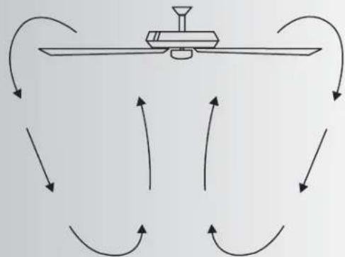
Warm weather - (Forward) A downward airflow creates a cooling effect as shown in Fig. 16. This allows you to set your air conditioner on a warmer setting without affecting your comfort.
Cool weather - (Reverse) An upward airflow moves warm air off the ceiling area as shown in Fig.17. This allows you to set your heating unit on a cooler setting without affecting your comfort.
14. TROUBLESHOOTING
Problem Solution
Fan will not start. 1. Check circuit fuses or breakers.
2. Check line wire connections to the fan and switch wire connections in the switch housing.
CAUTION: Make sure main power is off.
Fan sounds noisy. 1. Make sure all motor housing screws are snug.
2. Make sure the screws that attach the fan blade bracket to the motor hub is tight.
3. Make sure wire nut connections are not rubbing against each other or the interior wall of the switch housing.
CAUTION: Make sure main power is off.
4. Allow a 24-hour "breaking-in" period. Most noise associated with a new fan disappear during this time.
5. If using an optional light kit, make sure the screws securing the glassware are tight. Check that the light bulb is also secure.
6. Some fan motors are sensitive to signals from solid-state variable speed controls. If you have installed this type of control, choose and install another type of control.
7. Make sure the upper canopy is a short distance from the ceiling. It should not touch the ceiling.
Fan wobble. 1. Check that all blade and blade arm screws are secure.
2. Most fan wobbling problems are caused when blade levels are unequal. Check this level by selecting a point on the ceiling above the tip of one of the blades.
Measure this distance.(Fig. 21) Rotate the fan until the next blade is positioned for measurement. Repeat for each blade. The distance deviation should be equal within 1/8".
3. Use the enclosed Blade Balancing Kit if the blade wobble is still noticeable.
4. If the blade wobble is still noticeable, interchanging two adjacent (side by side) blades can redistribute the weight and possibly result in smoother operation.
WARNING: TO REDUCE THE RISK OF PERSONAL INJURY, DO NOT BEND THE BLADE ARM WHILE INSTALLING, BALANCING THE BLADES, OR CLEANING THE FAN. DO NOT INSERT FOREIGN OBJECTS BETWEEN ROTATING FAN BLADES.
15. SPECIFICATIONS
| Fan Size | Speed | Volts | Amps | Watts | RPM | CFM CFM/W | N.W. G | W. C.F. | ||
| 52" | High | 120 | 0.50 | 62 | 167 | 5282.35 | 85.20 | kgs | Xx kgs | xxx'Xx |
| Medium | 120 | 0.35 | 33 | 115 | 3549.65 | 107.57 | ||||
| Low | 120 | 0.23 | 16 | 70 | 2122.47 | 132.65 | ||||
These are approximate measures. They do not include Amps and Wattage used by the light kit.