Stratmoor - Lighting Kichler - Free user manual and instructions
Find the device manual for free Stratmoor Kichler in PDF.

User questions about Stratmoor Kichler
0 question about this device. Answer the ones you know or ask your own.
Ask a new question about this device
Download the instructions for your Lighting in PDF format for free! Find your manual Stratmoor - Kichler and take your electronic device back in hand. On this page are published all the documents necessary for the use of your device. Stratmoor by Kichler.
USER MANUAL Stratmoor Kichler
text_image
52" Stratmoor™ A Kichler® Select® ceiling fan Kichler® Lighting 7711 East Pleasant Valley Road P.O. Box 318010 Cleveland, Ohio 44131-6010 Customer Service 866.558.5706 8:30 AM to 5:00 PM EST, Monday - Friday Instruction Manual KICHLER LIGHTING1. SAFETY RULES
- To reduce the risk of electric shock, insure electricity has been turned off at the circuit breaker or fuse box before beginning.
- All wiring must be in accordance with the National Electrical Code and local electrical codes. Electrical installation should be performed by a qualified licensed electrician.
- WARNING: Suitable for use with solid-state speed controls.
- WARNING: To reduce the risk of personal injury, use only the two steel screws (and lock washers) provided with the outlet box for mounting to the outlet box. Most outlet boxes commonly used for the support of lighting fixtures are not acceptable for fan support and may need to be replaced, consult a qualified electrician if in doubt.
WARNING
TO REDUCE THE RISK OF FIRE, ELECTRIC SHOCK OR PERSONAL INJURY, MOUNT FAN TO OUTLET BOX MARKED "ACCEPTABLE FOR FAN SUPPORT".
- The outlet box and support structure must be securely mounted and capable of reliably supporting a minimum of 50 pounds. Use only CUL Listed outlet boxes marked "FOR FAN SUPPORT".
- The fan must be mounted with a minimum of 7 feet clearance from the trailing edge of the blades to the floor.
-
Do not operate reversing switch while fan blades are in motion. Fan must be turned off and blades stopped before reversing blade direction.
-
Avoid placing objects in the path of the blades.
- To avoid personal injury or damage to the fan and other items, be cautious when working around or cleaning the fan.
- Do not use water or detergents when cleaning the fan or fan blades. A dry dust cloth or lightly dampened cloth will be suitable for most cleaning.
- After making the electrical connections, spliced conductors should be turned upward and pushed carefully up into outlet box. The wires should be spread apart with the ground wire and white (common) wire to one side with the black (load) wire to the other side of the outlet box.
- Electrical diagrams are reference only. Light kits that are not packed with the fan must be CUL Listed and marked suitable for use with the model fan you are installing. Switches must be CUL General Use Switches. Refer to the Instructions packaged with the light kits and switches for proper assembly.
WARNING
TO REDUCE THE RISK OF PERSONAL INJURY, DO NOT BEND THE BLADE BRACKETS (ALSO REFERRED TO AS FLANGES) DURING ASSEMBLY OR AFTER INSTALLATION. DO NOT INSERT OBJECTS IN THE PATH OF THE BLADES.
2. TOOLS AND MATERIALS REQUIRED
● Philips screw driver
- Blade screw driver
● 11 mm wrench
- Step ladder
● Wire cutters
3. PACKAGE CONTENTS
Unpack your fan and check the contents. You should have the following items:
a. Fan blades (5)
b. Ceiling mounting plate
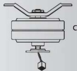
c. Motor and hanger bracket assembly
d. Motor housing
e. Set of 5 blade brackets and Pre-Installed mounting screws
f. Mounting plate
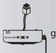
g. Switch housing
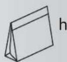
h. Part bag contents
1) Mounting hardware:
star washers (2), wire nuts (3),
machine screws (2), washers (2),
screws (2)
2) Blade attachment hardware: screws (17), washers (17), fiber washers (17)
3) Safety cable hardware: wood screw, lock washer, flat washer
4) Pull chain and fob
5) Balance Kit

natural_image
Line drawings of five different tools: screwdriver, wrench, ladder, pliers, and flatener (no text or symbols)
natural_image
Simple line drawing of a rounded rectangular shape with four small circular holes at the bottom (no text or symbols)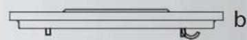
natural_image
Pure mechanical diagram of a lever or pump assembly without any text, numbers, or symbols
natural_image
Simple line drawing of a bowl with a side tab and label 'd' (no text or symbols on the object itself)


text_image
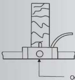
Outlet boxFig. 1
natural_image
Pure mechanical diagram showing a piston-like component with wavy internal lines and a curved arrow, no text or symbols present.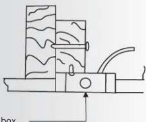
natural_image
Diagram of a mechanical device with layered components and a force arrow, no text or symbols presentFig. 2

text_image
Outlet boxFig. 3
4. MOUNTING OPTIONS
If there isn't an existing UL (cUL for Canadian Installation) listed mounting box, then read the following instructions. Disconnect the power by removing fuses or turning off circuit breakers.
Secure the outlet box directly to the building structure. Use appropriate fasteners and building materials. The outlet box and its support must be able to fully support the moving weight of the fan (at least 50 lbs). Do not use plastic outlet boxes.
Figures 1, 2 are examples of different ways to mount the outlet box.
NOTE: Depending on the location you have selected for installation, you may need to purchase and install a "Joist Hanger" for the support of the outlet box. Make sure the joist hanger you purchase has been designed for use with ceiling fans. (Fig. 3)
5. HANGING THE FAN
REMEMBER to turn off the power before you begin.
To properly install your ceiling fan, follow the steps below.
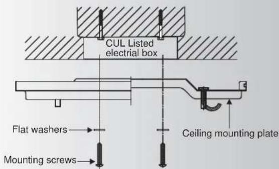
Step 1. Secure the ceiling mounting Plate to the ceiling outlet box using screws and washers included with your outlet box. (Fig. 4)
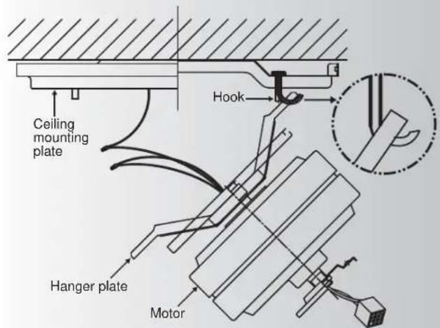
Step 2. Carefully lift the fan motor/hanger plate assembly up to the ceiling mounting plate and hang the assembly on the hook attached to one end of the ceiling mounting plate. See figure 5.
text_image
CUL Listed electrical box Flat washers Mounting screws Ceiling mounting plateFig. 4
text_image
Ceiling mounting plate Hook Hanger plate MotorFig. 5
text_image
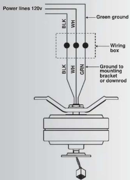
Power lines 120v BLK WH Green ground Wiring box BRK WH GRN Ground to mounting bracket or downrodFig. 6
6. ELECTRICAL CONNECTIONS
WARNING: To avoid possible electrical shock, be sure you have turned off the power at the main circuit panel.
Follow the steps below to connect the fan to your household wiring. Use the wire connecting nuts supplied with your fan. Secure the connectors with electrical tape. Make sure there are no loose wire strands or connections.
Step 1. Connect the fan supply (black) wire to the black household supply wire as shown in Figure 6.
Step 2. Connect the neutral fan (white) wire to the neutral household (white) wire.
Step 3. Connect the fan ground wire (green) to the household ground wire.
Step 4. After connecting the wires, spread them apart so that the green and white wires are on one side of the outlet box and the black wires is on the other side.
Step 5. Turn the connecting nuts upward and push the wiring into the outlet box.
WARNING: TO REDUCE THE RISK OF PERSONAL INJURY AND TO INUSRE THE PROPER OPERATION OF YOUR CEILING FAN. NEVER ATTACH THE BLADE ASSEMBLIES UNTIL THE CEILING FAN HAS BEEN MOUNTING ON THE CEILING. DO NOT BEND THE BLADE ARMS WHILE INSTALLING, BALANCING OR CLEANING THE FAN. DO NOT INSERT FOREIGN OBJECTS BETWEEN ROTATING FAN BLADES.
7. FINISHING THE INSTALLATION
Remove the four sets of nuts and washers located on the mounting plate threaded studs.
Hang the motor assembly from the hook on the ceiling mounting plate by placing the hook into a hole on the mounting plate.
Place the wires and connections inside the mounting plate and the ceiling mounting plate.
Swing the motor assembly up into position under the ceiling mounting plate, align the holes on the mounting plate with the four studs on the ceiling mounting plate and push the motor assembly onto the studs. Secure with the four nuts and washers you removed earlier. (Fig. 7)

text_image
Mounting plate threaded studs Ceiling mounting bracket Washer Nut Mounting plate Washers Nut Motor assemblyFig. 7
8. INSTALLING THE MOTOR HOUSING
Remove the four screws located on the outside edge of the ceiling mounting plate.
Lift the Motor Housing up and align the mounting holes in the housing to the mounting holes on the ceiling mounting plate.
Insert each mounting screw rotating first one side to the other and then tighten each screw after all four have been started. (Fig. 8)

text_image
Ceiling mounting plate Motor Screws Motor housingFig. 8
text_image
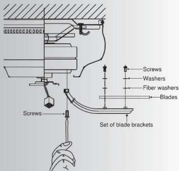
Screws Washers Fiber washers Blades Set of blade brackets ScrewsFig. 9
text_image
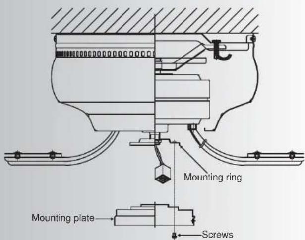
Mounting ring Mounting plate ScrewsFig. 10
9. ATTACHING THE FAN BLADES
Step 1. Place a blade on a blade bracket aliening the mounting holes on each. Start each set of mounting screws, washers and fiber pads into each hole.
Make sure the blade is straight on the blade bracket and tighten each mounting screw until the fiber pad is slightly compressed.
Step 2. Attach each blade assembly to the motor using the "Pre-installed" mounting screws in the blade bracket. (Fig 9)
Repeat the above process for each blade assembly.
10. INSTALLING THE SWITCH HOUSING PLATE
-
Loosen two screws on the mounting ring attached to the motor shaft and "remove" and save the third screw. (Fig. 10)
-
Place the key holes on the mounting plate over the 2 screws previously loosened from the mounting ring, turn mounting plate until it locks in place at the narrow section of the key holes. Secure by tightening the 2 screws previously loosened and the one previously removed. (Fig. 10)
11. INSTALLING THE SWITCH HOUSING
NOTE: Before continuing installation, confirm that the power is still turning off at the main circuit breaker or by removing the correct fuse. Turning the power off using a wall switch is not sufficient to prevent electrical shock.
- While holding the switch housing under your ceiling fan, push the square wire connectors together. One from the fan and one from the switch housing.
NOTE: These connectors are color coded and will ONLY engage when the colored strips are matched (aligned).
- Carefully push all the wires into the switch housing.
Attach the switch housing to the mounting plate with the screws provided. Make sure each screw is tight. (Fig. 11)
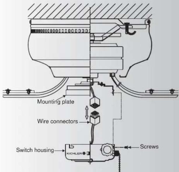
text_image
Mounting plate Wire connectors Switch housing KICHLER ScrewsFig. 11
natural_image
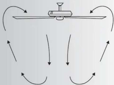
Diagram of airflow around a mechanical component with curved arrows indicating direction (no text or symbols)Fig. 12
flowchart
graph TD
    A["Central Device"] --> B{Flow Direction}
    B -->|Upward| C["Return to Left"]
    B -->|Downward| D["Return to Right"]
    B -->|Upward| E["Return to Left"]
    B -->|Downward| F["Return to Right"]
    style A fill:#f9f,stroke:#333
    style B fill:#ccf,stroke:#333
Fig. 13
12. OPERATING INSTRUCTIONS
The pull chain controls the 3 speeds of your ceiling fan.
1 pull = High, 2 pulls = Medium, 3 pulls = Low and the 4th pull turns the motor off.
The Black Slide Switch on the side of the switch housing controls the direction of the blades "Forward and Reverse".
Warm weather - Forward (counter clockwise) A downward airflow creates a cooling effect as shown in Fig. 12. This allows you to set your air conditioner on a warmer setting without affecting your comfort.
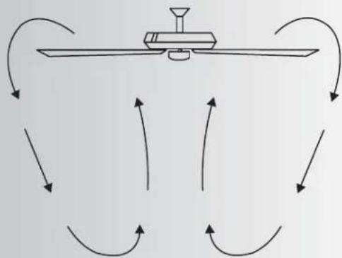
Cool weather - Reverse (clockwise) An upward airflow moves warm air off the ceiling area as shown in Fig. 13. This allows you to set your heating unit on a cooler setting without affecting your comfort.
13. TROUBLESHOOTING
Problem
Solution
Fan will not start.
- Check that all fuses or circuit breakers are installed or in the ON position.
- Check all electrical connections to insure proper contact. CAUTION: Make sure the main power is OFF when checking any electrical connection.
Fan sounds noisy.
- Make sure all motor housing screws are snug.
- Make sure the screws that attach the fan blade bracket to the motor hub is tight.
- Make sure wire nut connections are not rubbing against each other or the interior wall of the switch housing.
CAUTION: Make sure main power is off.
- Allow a 24-hour "breaking-in" period. Most noise associated with a new fan disappear during this time.
- If using an optional light kit, make sure the screws securing the glassware are tight. Make sure the light bulbs are not touching any other component.
- Some fan motors are sensitive to signals from solid-state variable speed controls. If you have installed this type of control, choose and install another type of control.
- Make sure the upper canopy is a short distance from the ceiling. It should not touch the ceiling.
Fan wobble.
- Check that all blade and blade arm screws are secure.
- Most fan wobbling problems are caused when blade levels are unequal. Check this level by selecting a point on the ceiling above the tip of one of the blades.
Measure this distance. Rotate the fan until the next blade is positioned for measurement. Repeat for each blade. The distance deviation should be equal within 1/8". - Use the enclosed Blade Balancing Kit if the blade wobble is still noticeable.
- If the blade wobble is still noticeable, interchanging two adjacent (side by side) blades can redistribute the weight and possibly result in smoother operation.
WARNING: TO REDUCE THE RISK OF PERSONAL INJURY AND TO INUSRE THE PROPER OPERATION OF YOUR CEILING FAN. NEVER ATTACH THE BLADE ASSEMBLIES UNTIL THE CEILING FAN HAS BEEN MOUNTING ON THE CEILING. DO NOT BEND THE BLADE ARMS WHILE INSTALLING, BALANCING OR CLEANING THE FAN. DO NOT INSERT FOREIGN OBJECTS BETWEEN ROTATING FAN BLADES.
14. SPECIFICATIONS
| Speed | Volts | Amps | Watts | RPM CFM | CFM/W N | N.W. G.W. | C.F.Fan Size | ||
| 52" | High | 120 | 0.49 | 59.0 | 160 | 4830 | 82 | 9.48 kgs | 10.02 kgs |
| Medium | 120 | 0.35 | 28.5 | 110 | 3323 | 119 | |||
| Low | 120 | 0.20 | 9.5 | 63 | 1779 | 187 | |||
These are approximate measures. They do not include Amps and Wattage used by the light fixture.