700PRV-1 - Pump FLUKE - Free user manual and instructions
Find the device manual for free 700PRV-1 FLUKE in PDF.

User questions about 700PRV-1 FLUKE
0 question about this device. Answer the ones you know or ask your own.
Ask a new question about this device
Download the instructions for your Pump in PDF format for free! Find your manual 700PRV-1 - FLUKE and take your electronic device back in hand. On this page are published all the documents necessary for the use of your device. 700PRV-1 by FLUKE.
USER MANUAL 700PRV-1 FLUKE
The Fluke 700PRV Pressure Relief Valve Kit consists of two adjustable pressure relief valves for the Fluke 700HTP Hydraulic Test Pump. The two valves provide a pressure relief setting range of 50 to 400 bar (725 to 5,800 psi).
The 700HTP pump can develop pressures up to 700 bar (10,150 psi). Application of too much pressure can damage some pressure instruments. The pressure relief valves in this kit provide a way to protect pressure instruments from accidental overpressure. When the applied pressure reaches the relief setting of the valve, the valve opens a channel to release hydraulic fluid pressure back into the hydraulic fluid reservoir.
Specifications
| Valve Preset Value(±10%) | Relief Setting Range | |
| Low Range:PRV12-2-HTP1 | 94 bar(1360 psi) | 50 to 200 bar(725 to 2,900 psi) |
| High Range:PRV12-3-HTP1 | 376 bar(5,450 psi) | 200 to 400 bar(2,900 to 5,800 psi) |
Pressure Connection: 1/4-in BSP male, parallel thread. This mates with the pressure relief valve port on the 700HTP pump.
Pressure Relief Adjustment Method: Multiturn adjustment screw to set preload on disc springs.
Repeatability of relief setting: ±10% of nominal setting
Material: 303 stainless steel
Dimensions (each): 1.57 in by 0.87 in diameter (40 mm by 22 mm diameter)
Weight (each): 2.1 oz (60 g)
Features of the Pressure Relief Valve

text_image
Cutaway view Nylon seal O-ring seal Adjustment screw Reservoir Protective cappv02f.eps
The adjustment screw is a cylinder, and has a slot for an adjustment tool. The adjustment screw compresses a spring, which determines the relief (cracking) pressure setting.
Hydraulic fluid inlet and outlet ports are machined into the body of the 700HTP pump, and are designed for this valve. When the pressure relief valve is not in use, a threaded plug must be installed in the pump's pressure relief valve port.
Selecting Which Valve to Use
The following table lists the suggested pressure relief valve for the Fluke Pressure Modules in the 35 bar (500 psi) and higher ranges.
| Fluke 700 Series Pressure Module | Suggest Pressure Relief Valve |
| 700P07, 700P08, 700P09 Low range (PRV12-2-HTP1) | |
| 700P29, 700P30, 700P31 High range (PRV12-3-HTP1) | |
Installing a Pressure Relief Valve
text_image
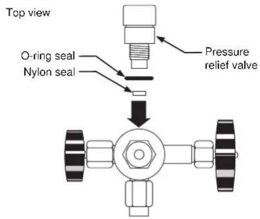
Top view O-ring seal Nylon seal Pressure relief valvepv011.eps
Install a pressure relief valve as shown in the figure above. Install the nylon seal in the 700HTP pressure relief valve port first, followed by the O-ring and pressure relief valve.
Note
Use only the nylon seal provided, never thread sealing tape, with parallel threads.
Adjusting the Pressure Relief Setting
Set the pressure relief by trial and error. The table under Specifications shows the preset pressure relief settings at time of shipment. To set the pressure relief lower, turn the adjustment screw counter-clockwise (loosen it). To set the pressure relief higher, turn the adjustment screw clockwise (tighten it).
How to Contact Fluke
To contact Fluke, call one of the following numbers:
1-800-44-FLUKE (1-800-443-5853) in U.S.A. and Canada
+31 402-678-200 in Europe
+81-3-3434-0181 in Japan
+65- ^* -276-6196 in Singapore
+1-425-356-5500 in other countries
Visit us on the World Wide Web at:
www.fluke.com
Limited Warranty & Limitation of Liability
This Fluke product will be free from defects in material and workmanship for one year from the date of purchase. This warranty does not cover fuses, disposable batteries or damage from accident, neglect, misuse or abnormal conditions of operation or handling. Resellers are not authorized to extend any other warranty on Fluke's behalf. To obtain service during the warranty period, send your defective calibrator to the nearest Fluke Authorized Service Center with a description of the problem. THIS WARRANTY IS YOUR ONLY REMEDY. NO OTHER WARRANTIES, SUCH AS FITNESS FOR A PARTICULAR PURPOSE, ARE EXPRESSED OR IMPLIED. FLUKE IS NOT LIABLE FOR ANY SPECIAL, INDIRECT, INCIDENTAL OR CONSEQUENTIAL DAMAGES OR LOSSES, ARISING FROM ANY CAUSE OR THEORY. Since some states or countries do not allow the exclusion or limitation of an implied warranty or of incidental or consequential damages, this limitation of liability may not apply to you.
Fluke Corporation Fluke Europe B.V.
P.O. Box 9090 P.O. Box 1186
Everett, WA 98206-9090 5602 B.D. Eindhoven
U.S.A. The Netherlands