700LTP-1 - Pump FLUKE - Free user manual and instructions
Find the device manual for free 700LTP-1 FLUKE in PDF.


| Product Type | Pneumatic Pressure Pump |
| Brand | Fluke |
| Model | 700LTP-1 |
| Pressure Range | -0.8 to 20 bar (-12 to 300 psi) |
| Maximum Pressure | 20 bar (300 psi) |
| Vacuum Capability | Down to -0.8 bar (-12 psi) |
| Medium | Clean dry air or nitrogen |
| Connection | 1/4 inch NPT female |
| Dimensions (L x W x H) | 200 mm x 120 mm x 80 mm (7.9 x 4.7 x 3.1 in) |
| Weight | 0.8 kg (1.8 lb) |
| Material | Anodized aluminum and brass |
| Operating Temperature | 0°C to 50°C (32°F to 122°F) |
| Storage Temperature | -20°C to 70°C (-4°F to 158°F) |
| Humidity | 0-95% non-condensing |
| Primary Function | Generation and regulation of pressure for calibration |
| Fine Adjustment | Precision vernier adjustment valve |
| Pressure Release | Integrated pressure relief valve |
| Maintenance | Periodic cleaning and seal replacement |
| Cleaning | Wipe with a damp cloth; do not use solvents |
| Safety Features | Overpressure protection, non-sparking materials |
| Warranty | 1 year (standard) |
| Included Accessories | Carrying case, test leads, adapters |
Frequently Asked Questions - 700LTP-1 FLUKE
User questions about 700LTP-1 FLUKE
0 question about this device. Answer the ones you know or ask your own.
Ask a new question about this device
Download the instructions for your Pump in PDF format for free! Find your manual 700LTP-1 - FLUKE and take your electronic device back in hand. On this page are published all the documents necessary for the use of your device. 700LTP-1 by FLUKE.
USER MANUAL 700LTP-1 FLUKE
Low-Pressure Test Pump
Instruction Sheet
Introduction
The Fluke-700LTP-1 Low-Pressure Test Pump is a portable, dual source of vacuum and pressure. Each pump incorporates a vacuum and pressure selector and fine adjustment control. The pump has the following specifications:
• Output pressure: 0 to 100 psi / 0 to 6.9 bar
• Output vacuum: 0 to -13 psi / 0 to -900 mbar
- Exposed Materials: Aluminum, silicon, neoprene, stainless steel, Buna-N
- Adjustment: Fine volumetric pressure and vacuum adjuster
• Dimensions: 150 mm x 100 mm
• Weight: 226 grams or .5 lbs (pump only)
Box Contents
- Fluke 700LTP-1 Low-pressure Test Pump
• 1/8 in NPT male/female tee
• (2) 1 m hoses
• (4) 1/8 in NPT male quick connects
• (2) 1/8 NPT female to 1/4 in BSP female - Seal Kit
- Instruction Sheet
Contacting Fluke
To contact Fluke or for service, call one of the following telephone numbers:
USA: 1-888-44-FLUKE (1-888-443-5853)
Canada: 1-800-36-FLUKE (1-800-363-5853)
Europe: +31 402-675-200
Japan: +81-3-3434-0181
Singapore: +65-738-5655
Anywhere in the world: +1-425-446-5500
Or, visit Fluke's Web site at www.fluke.com.
| eus01f.eps | |
| ① | Pressure/vacuum release valve- Turn valve counter-clockwise for vacuum, clockwise for pressure and centered for release. |
| ② | Fine adjustment control- Turn in or out to increase or decrease pressure accordingly. |
| ③ | Master and test port tee |
| ④ | Quick-fit connectors |
| ⑤ | Hose |
| ⑥ | 1/8 in NPT female to 1/4 in BSP female fitting |
| ⑦ | Pump Handle. If the pump has not been used for a while, there may be some resistance on the first stroke. |
| ⑧ | Cleanout ports (2)- See cleanout instructions |
Figure 1. Features
Guidelines for Use
- Connect a pressure calibrator or pressure module to the quick-fit connector (item ④) at the end of one of the flexible hoses (item ⑤).
- Connect the unit under test to the quick-fit connector (item ④) at the end of the second flexible hose (item ⑤), choosing correct adapters (item ⑥) and seals.
- Turn the fine adjustment control to mid-range.
- Set control valve to pressure.
- Operate handle (item ⑦) until the pressure is close to the required value.
Notes
- The pressure may settle for up to one minute after increasing pressure due to the thermodynamic effects, settling of seals and expansion of the flexible hose.
-
On very high resolutions such as 1 mbar or 0.1 inches of water, small movements of the tubing may result in noticeable pressure changes.
-
Turn the fine adjustment control (item ②) in to increase pressure or out to decrease pressure until required pressure is reached.
-
Reduce pressure by careful use of the pressure release valve (item ①).
-
Achieve vacuum using the above procedure with the pressure / vacuum selector (item ①) in the vacuum position.
When testing for leaks, you may notice that air is drawn in or expelled from around the pressure / vacuum selector. This is normal operation.
If the pump appears to lose pressure, then the procedure above should be repeated, ensuring new seals are used, adapters are tightened sufficiently and the pressure release valve (item ①) is tightened firmly. The connections to the handheld test system are sealed with o-ring or bonded seals and should not leak.
Pump Valve Assembly Cleaning Instructions
Occasionally, the 700LTP-1 may not work properly due to contamination of the internal valve assembly. Use the following procedure to clean the valve assembly. If the procedure does not fix the problem, a rebuild kit (2812587) may be ordered.
- Using a small screwdriver, remove the 2 valve retention caps located on opposite sides of the pump below the pressure/vacuum switch.
- Gently remove the spring and o-ring assembly. This includes several small components. Remove with care. See Figure 2.
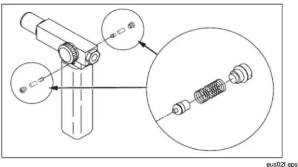
Figure 2. Disassembly
- Set aside the valve assemblies and clean out the valve body using a cotton swab soaked in isopropyl alcohol.
- Repeat the process several times using a new swab until clean.
- Operate the pump handles several times and recheck for contamination.
- Clean the o-ring assembly and the o-ring on the retention caps with isopropyl alcohol and inspect the o-rings closely for any damage or excessive wear. Replacements are included in the repair kit.
- Inspect the springs for wear or loss of tension. They should be approximately 8.6 mm long in the relaxed state. If shorter, they may provide sufficient sealing tension. Replace if needed.
- Once all parts have been cleaned and inspected, reinstall the o-ring and spring assembly into the valve body.
- Reinstall the retention caps and gently tighten each cap.
- Seal the output port and operate the pump to at least 50 % of capacity.
- Release the pressure and repeat several times to ensure that the o-rings seat properly.
Replacement Parts
• Hose Assembly, Fluke PN 2815714
• Rebuild Kit, Fluke PN 2812587
LIMITED WARRANTY AND LIMITATION OF LIABILITY
This Fluke product will be free from defects in material and workmanship for one year from the date of purchase. This warranty does not cover fuses, disposable batteries, or damage from accident, neglect, misuse, alteration, contamination, or abnormal conditions of operation or handling. Resellers are not authorized to extend any other warranty on Fluke's behalf. To obtain service during the warranty period, contact your nearest Fluke authorized service center to obtain return authorization information, then send the product to that Service Center with a description of the problem. THIS WARRANTY IS YOUR ONLY REMEDY. NO OTHER WARRANTIES, SUCH AS FITNESS FOR A PARTICULAR PURPOSE, ARE EXPRESSED OR IMPLIED. FLUKE IS NOT LIABLE FOR ANY SPECIAL, INDIRECT, INCIDENTAL OR CONSEQUENTIAL DAMAGES OR LOSSES, ARISING FROM ANY CAUSE OR THEORY. Since some states or countries do not allow the exclusion or limitation of an implied warranty or of incidental or consequential damages, this limitation of liability may not apply to you.
Fluke Corporation Fluke Europe B.V. P.O. Box 9090 P.O. Box 1186 Everett, WA 98206-9090 5602 BD Eindhoven U.S.A. The Netherlands
11/99
Brand : FLUKE
Model : 700LTP-1
Category : Pump