Profile JP989TDWW - Cooker GE - Free user manual and instructions
Find the device manual for free Profile JP989TDWW GE in PDF.

User questions about Profile JP989TDWW GE
0 question about this device. Answer the ones you know or ask your own.
Ask a new question about this device
Download the instructions for your Cooker in PDF format for free! Find your manual Profile JP989TDWW - GE and take your electronic device back in hand. On this page are published all the documents necessary for the use of your device. Profile JP989TDWW by GE.
USER MANUAL Profile JP989TDWW GE
Radiant Downdraft Cooktop
Safety Instructions .....2-5
Operating Instructions
Bridge Burner 8
Cooktop Vent System .....8
Cookware Tips 9
Dual Surface Unit ....8
Features of Your Cooktop .....6
Surface Units 7,8
Temperature Limiter .....8
Care and Cleaning
Control Knobs ....10
Glass Cooktop .....11, 12
Vent Filter ....10
Vent System .....10
Installation Instructions
Ductwork .....17-20, 24
Electrical Connections .....24–26
Exhaust Blower Ratings .....19
Final Assembly .....27
Installing the Cooktop .....22-24
Installing the Gasket .....21
Preparation .....15–17
Safety Precautions .....13
Unpacking the Cooktop ....14, 21
Troubleshooting Tips .....28
Consumer Support
Consumer Support .....32
Product Registration .....29, 30
Warranty....31
Write the model and serial numbers here:
Model # ____
Serial #
Find these numbers on a label under the cooktop, on the side of the vent chamber.
Owner's Manual & Installation Instructions
JP989
IMPORTANT SAFETY INFORMATION. READ ALL INSTRUCTIONS BEFORE USING.

SAFETY PRECAUTIONS
WARNING — TO REDUCE THE RISK OF FIRE, ELECTRIC SHOCK OR INJURY TO PERSONS, OBSERVE THE FOLLOWING:
A. Use this unit only in the manner intended by the manufacturer. If you have questions, contact the manufacturer.
B. Before servicing or cleaning unit, switch power off at service panel and lock the service disconnecting means to prevent power from being switched on accidentally. When the service disconnecting means cannot be locked, securely fasten a prominent warning device, such as a tag, to the service panel.
C. Do not use this unit with any solid-state speed control device.
D. This unit must be grounded.
CAUTION — For general ventilating use only. Do not use to exhaust hazardous or explosive materials and vapors.
WARNING — TO REDUCE THE RISK OF INJURY TO PERSONS IN THE EVENT OF A COOKTOP GREASE FIRE, OBSERVE THE FOLLOWING\*:
A. SMOTHER FLAMES with a close-fitting lid, cookie sheet or metal tray, then turn off the burner. BE CAREFUL TO PREVENT BURNS. If the flames do not go out immediately, EVACUATE AND CALL THE FIRE DEPARTMENT.
B. NEVER PICK UP A FLAMING PAN—
You may be burned.
C. DO NOT USE WATER, including wet dishcloths or towels—a violent steam explosion will result.
D. Use an extinguisher ONLY if:
- You know you have a Class ABC extinguisher, and you already know how to operate it.
- The fire is small and contained in the area where it started.
- The fire department is being called.
- You can fight the fire with your back to an exit.
* Based on "Kitchen Firesafety Tips" published by NFPA.
WARNING — TO REDUCE THE RISK OF A COOKTOP GREASE FIRE:
A. Never leave surface units unattended at high settings. Boilovers cause smoking and greasy spillovers that may ignite. Heat oils slowly on low or medium settings.
B. Always turn hood ON when cooking on high heat or when flambeing food (i.e. Crepes Suzette, Cherries Jubilee, Peppercorn Beef Flambé).
C. Clean ventilating fans frequently. Grease should not be allowed to accumulate on fan or filter.
D. Use proper pan size. Always use cookware appropriate for the size of the surface element.
WARNING — TO REDUCE THE RISK OF FIRE, ELECTRIC SHOCK OR INJURY TO PERSONS, OBSERVE THE FOLLOWING:
A. Installation work and electrical wiring must be done by qualified person(s) in accordance with all applicable codes and standards, including fire-rated construction.
B. Sufficient air is needed for proper combustion and exhausting of gases through the flue (chimney) of fuel burning equipment to prevent back drafting. Follow the heating equipment manufacturer's guideline and safety standards such as those published by the National Fire Protection Association (NFPA), and the American Society for Heating, Refrigeration and Air Conditioning Engineers (ASHRAE), and the local code authorities.
C. When cutting or drilling into wall or ceiling, do not damage electrical wiring and other hidden utilities.
D. Ducted fans must always be vented to the outdoors.
WARNING — TO REDUCE THE RISK OF FIRE, USE ONLY METAL DUCTWORK.
Do not attempt to repair or replace any part of your downdraft cooktop unless it is specifically recommended in this manual. All other servicing should be referred to a qualified technician.
⚠ WARNING!
For your safety, the information in this manual must be followed to minimize the risk of fire or explosion, electric shock, or to prevent property damage, personal injury, or loss of life.

SAFETY PRECAUTIONS
When using electrical appliances, basic safety precautions should be followed, including the following:
- Be sure your appliance is properly installed and grounded by a qualified technician in accordance with local codes and the provided installation instructions.
■Have the installer show you the location of the circuit breaker or fuse. Mark it for easy reference.
Do not leave children alone—children should not be left alone or unattended in an area where an appliance is in use. They should never be allowed to sit or stand on any part of the appliance.
■ Teach children not to play with the controls or any other part of the cooktop.
- Do not allow anyone to climb, stand or hang on the cooktop.
■ CAUTION: Items of interest to children should not be stored in cabinets above a cooktop—children climbing on the cooktop to reach items could be seriously injured.
■ Always keep combustible wall coverings, curtains or drapes a safe distance from your cooktop.
■ Always keep dish towels, dishcloths, pot holders and other linens a safe distance away from your cooktop.
■Always keep wooden and plastic utensils and canned food a safe distance away from your cooktop.
Never wear loose-fitting or hanging garments while using the appliance. Flammable material could be ignited if brought in contact with hot surface units and may cause severe burns.
■ Use only dry pot holders—moist or damp pot holders on hot surfaces may result in burns from steam. Do not let pot holders touch hot surface units. Do not use a towel or other bulky cloth. Such cloths can catch fire on a hot surface unit.
For your safety, never use your appliance for warming or heating the room.
Do not use water on grease fires. Never pick up a flaming pan. Turn the controls off. Smother a flaming pan on a surface unit by covering the pan completely with well-fitting lid, cookie sheet or flat tray. Use a multi-purpose dry chemical or foam-type extinguisher.
Flaming grease outside a pan can be put out by covering with baking soda or, if available, by using a multi-purpose dry chemical or foam-type fire extinguisher.

COOK MEAT AND POULTRY THOROUGHLY...
Cook meat and poultry thoroughly—meat to at least an INTERNAL temperature of 160^ F and poultry to at least an INTERNAL temperature of 180^ F. Cooking to these temperatures usually protects against foodborne illness.
IMPORTANT SAFETY INFORMATION. READ ALL INSTRUCTIONS BEFORE USING.

▲WARNING!
SAFETY PRECAUTIONS
Do not let cooking grease or other flammable materials accumulate on the cooktop.
Do not touch surface units. These surfaces may be hot enough to burn even though they are dark in color. During and after use, do not touch, or let clothing or other flammable materials contact the surface units or areas nearby the surface units; allow sufficient time for cooling first.
Potentially hot surfaces include the cooktop and areas facing the cooktop.
To minimize the possibility of burns, ignition of flammable materials and spillage, the handle of a container should be turned toward the center of the cooktop without extending over any nearby surface units.
■ Always turn the surface unit control to off before removing the cookware.
Use proper pan size—Select cookware having flat bottoms large enough to cover the surface unit heating element. The use of undersized cookware will expose a portion of the surface unit to direct contact and may result in ignition of clothing. Proper relationship of cookware to burner will also improve efficiency.
Never leave surface units unattended at high heat settings. Boilovers cause smoking and greasy spillovers that may catch on fire.
Only certain types of glass, glass/ceramic, earthenware or other glazed containers are suitable for cooktop cooking; others may break because of the sudden change in temperature.
- Keep an eye on foods being fried at high or medium high heat settings.
■ Foods for frying should be as dry as possible. Frost on frozen foods or moisture on fresh foods can cause hot fat to bubble up and over the sides of the pan.
■ Use little fat for effective shallow or deep-fat frying. Filling the pan too full of fat can cause spillovers when food is added.
If a combination of oils or fats will be used in frying, stir together before heating, or as fats melt slowly.
■Always heat fat slowly and watch as it heats.
■ Use a deep fat thermometer whenever possible to prevent overheating fat beyond the smoking point.
■Never try to move a pan of hot fat, especially a deep fat fryer. Wait until the fat is cool.
■ Do not store flammable materials near the cooktop.
- Keep the vent grille and grease filters clean to maintain good venting and to avoid grease fires.
Do not store or use combustible materials, gasoline or other flammable vapors and liquids in the vicinity of this or any appliance.
Clean only parts listed in this Owner's Manual.
■ Do not leave paper products, cooking utensils or food on the cooktop when not in use.
- Keep cooktop clean and free of accumulation of grease or spillovers which may ignite.
■ Never heat unopened food containers. Pressure buildup may make container burst and cause injury.
■ Never leave jars or cans of fat drippings on or near your cooktop.
RADIANT SURFACE UNITS
Use care when touching the cooktop. The glass surface of the cooktop will retain heat after the controls have been turned off.
■ Avoid scratching the glass cooktop. The cooktop can be scratched with items such as sharp instruments, rings or other jewelry and rivets on clothing.
Large scratches or impacts to glass cooktops can lead to broken or shattered glass.
■ Never use the glass cooktop surface as a cutting board.
Do not place or store items on top of the glass cooktop surface when it is not in use.
Be careful when placing spoons or other stirring utensils on glass cooktop surface when it is in use. They may become hot and could cause burns.
■ Avoid heating an empty pan. Doing so may damage the cooktop and the pan.
- Do not allow water, other liquids or grease to remain on the cooktop.
To minimize the possibility of burns, always be certain that the controls for all surface units are at the off position and the entire glass surface is cool before attempting to clean the cooktop.
Do not operate the glass surface units if the glass is broken. Spillovers or cleaning solution may penetrate a broken cooktop and create a risk of electrical shock. Contact a qualified technician immediately should your glass cooktop become broken.
Clean the cooktop with caution. If a wet sponge or cloth is used to wipe spills on a hot surface unit, be careful to avoid steam burns. Some cleansers can produce noxious fumes if applied to a hot surface.
NOTE: We recommend that you avoid wiping any surface unit areas until they have cooled and the indicator light has gone off. Sugar spills are the exception to this. Please see Cleaning the Glass Cooktop in the Care and Cleaning section.
When the cooktop is cool, use only CERAMA BRYTE® Ceramic Cooktop Cleaner and the CERAMA BRYTE® Cleaning Pad to clean the cooktop.
To avoid possible damage to the cooking surface, do not apply the cleaning cream to the glass surface when it is hot.
■ After cleaning, use a dry cloth or paper towel to remove all the cleaning cream residue.
Read and follow all instructions and warnings on the cleaning cream labels.

READ AND FOLLOW THIS SAFETY INFORMATION CAREFULLY.
SAVE THESE INSTRUCTIONS
Features of Your Cooktop.
Throughout this manual, features and appearance may vary from your model.
text_image
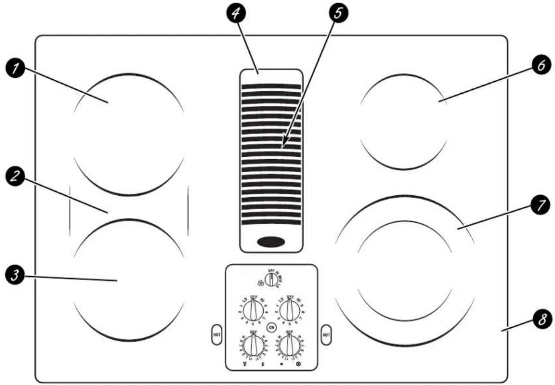
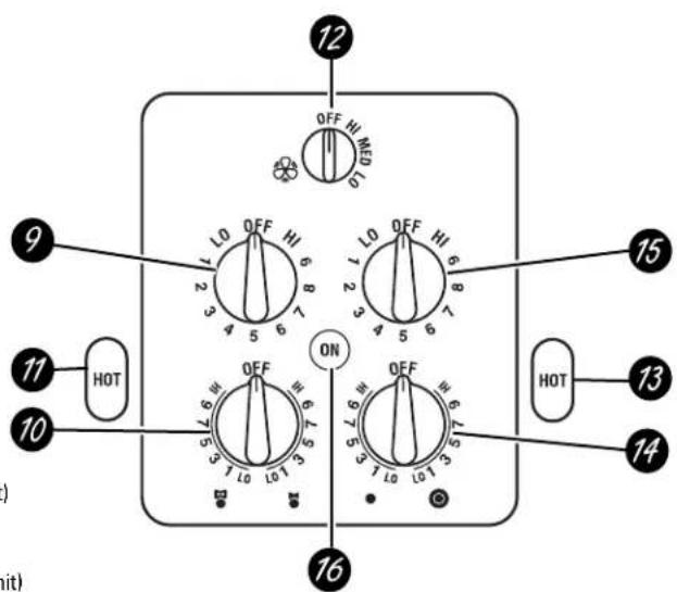
Diagram of a home control panel with labeled components and a rotary switch display showing four rotary switches.Feature Index (Features and appearance may vary)
7 Left Rear Surface Unit
2 Bridge Surface Unit
3 Left Front Surface Unit
Vent Grille
5 Vent Filter (below the vent grille)
6 Right Rear Surface Unit
7 Dual Surface Unit
8 Model and Serial Number Label (under the cooktop, on the right side of the vent chamber)
9 Left Rear Surface Unit Control
10 Left Front Surface Unit Control
11 Left Side Hot Surface Indicator Lights (one for each surface unit)
12 Vent Fan Speed Control
13 Right Side Hot Surface Indicator Lights (one for each surface unit)
14 Dual Surface Unit Control
15 Right Rear Surface Unit Control
16 Surface Unit On Indicator Light
text_image
12 OFF HI MEI LO 9 LO OFF HI 6 7 8 9 10 4 5 6 7 8 3 4 5 6 7 8 2 ON 11 HOT 10 16 HOT 13 14 ( )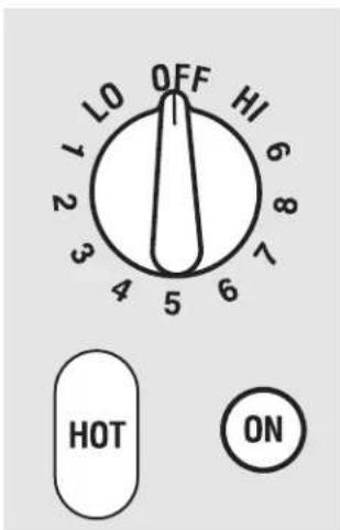
text_image
LO OFF HI 1 2 3 4 5 6 7 8 HOT ONBe sure you turn the control knob to OFF when you finish cooking.
Radiant Surface Units
The control for the radiant surface unit can be set anywhere between LO and HI for an unlimited number of heat settings. With the infinite switch the coil cycles on and off to maintain your selected control setting.
To bring liquids to a boil faster, use a lid to cover the pan.
The control knob must be pushed down and turned from the OFF position. When the control knobs are in any position other than off, they may be turned without pushing down.
Be sure you turn the control knob off when you finish cooking. You will feel a click at the OFF position.
The surface unit ON indicator light will glow when any surface unit is on.
NOTE: The surface unit ON indicator light may glow between the surface control settings of LO and OFF, but there is no power to the surface units.
Cooktop temperatures increase with the number of surface units that are on. With 3 or 4 units turned on, surface temperatures are high so be careful when touching the cooktop.
The HOT SURFACE indicator lights will glow when any radiant element is turned on, and will remain on until the surface is cooled to approximately 150°F.
NOTE:
Hot Surface Indicator Lights come on instantly and stay on even after the surface unit is turned off.
■ They glow brightly until the unit is cooled to approximately 150°F.
text_image
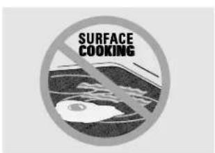
SURFACE COOKINGNever cook directly on the glass. Always use cookware.

text_image
OFF CENTERAlways place the pan in the center of the surface unit you are cooking on.
text_image
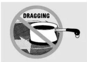
DRAGGINGDo not slide cookware across the cooktop because it can scratch the glass. The glass is scratch-resistant, not scratchproof.
About the radiant surface units...
The radiant cooktop features heating units beneath a smooth glass surface.
NOTE: A slight odor is normal when a new cooktop is used for the first time. It is caused by the heating of new parts and insulating materials and will disappear in a short time.
NOTE: On models with light colored glass cooktops, it is normal for the cooking zones to change color when hot or cooling down. This is temporary and will disappear as the glass cools to room temperature.
The surface unit will cycle on and off to maintain your selected control setting.
It is safe to place hot cookware from the oven or surface on the glass surface when the surface is cool.
Even after the surface units are turned off, the glass cooktop retains enough heat to continue cooking. To avoid over-cooking, remove pans from the surface units when the food is cooked. Avoid placing anything on the surface unit until it has cooled completely.
Water stains (mineral deposits) are removable using the cleaning cream or full strength white vinegar.
■ Use of window cleaner may leave an iridescent film on the cooktop. The cleaning cream will remove this discoloration.
- Don't store heavy items above the cooktop. If they drop onto the cooktop, they can cause damage.
- Do not use the surface as a cutting board.
Using the surface units.

text_image
OFF Small 6" → Large 9" surface unit setting surface unit settingDual Surface Unit
The right front surface unit has 2 cooking sizes to select from so you can match the size of the unit to the size of the cookware you are using.
To use the large (9-inch) surface unit, turn the knob clockwise to 📄d select the desired setting. The unit will heat the entire area contained by the larger circle.
To use the small (6-inch) surface unit, turn the knob counterclockwise to □ and select the desired setting. The unit will only heat the area inside the smaller circle.

text_image
OFF 19 6 5 7 3 5 9 1 L0 L0 1 3 Front Burner only → Front Burner and Bridge →Bridge Surface Unit
Make sure the pan rests flat on the glass cooktop and it is not resting on the trim. If you notice poor cooking performance, move the pan to make sure it is flat on the cooktop.
To use the bridge burner, turn the burner knob to find select the desired setting. The unit will heat the front surface burner and the bridge.
Choose pans that match the circle/bridge area as closely as possible.
To use only the front surface unit, turn the burner knob to and select the desired setting. The unit will only heat the front surface burner.
You can create an oblong heated area by using the left rear unit in addition to the front unit bridge combination.
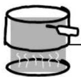
Temperature Limiter
Every radiant surface unit has a temperature limiter.
The temperature limiter protects the glass cooktop from getting too hot.
The temperature limiter may cycle the units off for a time if:
The cooktop is on while cooking.
The pan boils dry.
The pan bottom is not flat.
The pan is off-center.
There is no pan on the unit.

text_image
OFF HI MED LOHow to Operate the Vent System
The built-in vent system helps remove cooking vapors, odors and smoke from foods prepared on the cooktop.
To operate the downdraft vent system, turn the vent fan speed control knob to HI, MED, or LO, as needed.
Continuous use of the vent system while cooking helps keep the kitchen comfortable and less humid, reducing cooking odors and soiling moisture that normally creates a frequent need for cleaning.
The following information will help you choose cookware which will give good performance on glass cooktops.
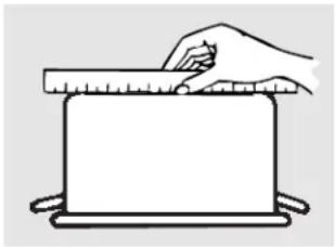
natural_image
Simple line drawing of a hand using a ruler to press a rectangular object on a tray (no text or symbols)Check pans for flat bottoms by using a straight edge.
Stainless Steel:
recommended
Aluminum:
heavy weight recommended
Good conductivity. Aluminum residues sometimes appear as scratches on the cooktop, but can be removed if cleaned immediately. Because of its low melting point, thin weight aluminum should not be used.
Glass-Ceramic:
usable, but not recommended
Poor performance. May scratch the surface.
Stoneware:
usable, but not recommended
Poor performance. May scratch the surface.
text_image
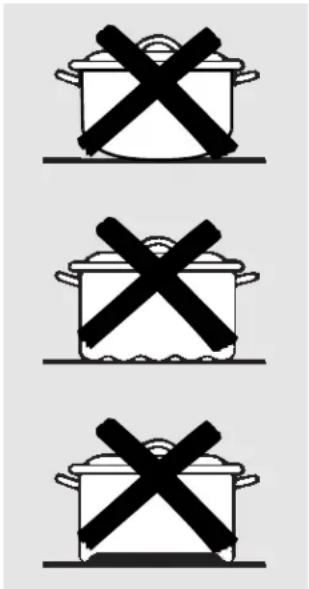
Three identical cooking pots with black X-shaped symbols, likely indicating prohibition or resistance.Pans with rounded, curved, ridged or warped bottoms are not recommended.
Copper Bottom:
recommended
Copper may leave residues which can appear as scratches. The residues can be removed, as long as the cooktop is cleaned immediately. However, do not let these pots boil dry. Overheated metal can bond to glass cooktops. An overheated copper bottom pot will leave a residue that will permanently stain the cooktop if not removed immediately.
Porcelain Enamel Covered Cast Iron:
recommended
As long as the cookware is covered completely with porcelain enamel, this cookware is recommended. Caution is recommended for cast iron cookware that is not completely covered with smooth porcelain enamel, since it may scratch the glass-ceramic cooktop.
Care and cleaning of the cooktop.
Be sure electrical power is off and all surfaces are cool before cleaning any part of the cooktop.
Vent System
Before cleaning the vent grille, be sure the exhaust blower is turned off.
To clean the vent grille, remove it from the cooktop by lifting it up and off. Wipe with a damp cloth. If necessary, the vent grille can be washed in the sink. Use dishwashing liquid for cleaning.
Do not use abrasive cleaners. They will damage the vent grille's finish.
Do not clean the vent grille in the dishwasher.
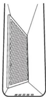
Vent Filter
The filter is held in place at an angle with a hold bump. Lift the filter up and out of the vent opening diagonally.
Clean the filter by swishing it in hot, soapy water. Rinse well and dry thoroughly.
Do not operate the vent without the filter in place.

text_image
Vent Filter Vent ChamberRemove and replace the filter diagonally through the vent opening.
To order filters please call our toll-free number:
National Parts Center......800.626.2002
Filter.....# WB02X10651
Do not operate the vent without the filter in place.
natural_image
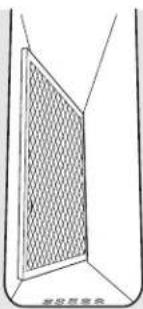
Simple line drawing of a door with a mesh grille and label '高光开关柜' (no other text or symbols)When replacing the filter, make sure it rests, at an angle, on the supports in the vent opening.
To clean the vent chamber, use hot, soapy water. Do not use abrasive cleaners; they will damage the finish. Replace the filter after it is cleaned and dry.

text_image
Shaped areaControl Knobs
The control knobs may be removed for easier cleaning.
Make sure the knobs are in the OFF positions and pull them straight off the stems for cleaning.
The knobs can be cleaned in a dishwasher or they may also be washed with soap and water. Make sure the insides of the knobs are dry before replacing.
Replace the knobs in the OFF position to ensure proper placement.

text_image
CERAMA BRYTEClean your cooktop after each spill. Use CERAMA BRYTE® Ceramic Cooktop Cleaner.
Normal Daily Use Cleaning
ONLY use CERAMA BRYTE® Ceramic Cooktop Cleaner on the glass cooktop. Other creams may not be as effective.
To maintain and protect the surface of your glass cooktop, follow these steps:
Before using the cooktop for the first time, clean it with CERAMA BRYTE® Ceramic Cooktop Cleaner. This helps protect the top and makes clean-up easier.
2 Daily use of CERAMA BRYTE® Ceramic Cooktop Cleaner will help keep the cooktop looking new.
3 Shake the cleaning cream well. Apply a few drops of CERAMA BRYTE® Ceramic Cooktop Cleaner directly to the cooktop.
4 Use a paper towel or CERAMA BRYTE® Cleaning Pad for Ceramic Cooktops to clean the entire cooktop surface.
5 Use a dry cloth or paper towel to remove all cleaning residue. No need to rinse.
NOTE: It is very important that you DO NOT heat the cooktop until it has been cleaned thoroughly.

natural_image
Hand using a tool to clean or store food on a circular stove (no text or symbols visible)Use a CERAMA BRYTE® Cleaning Pad for Ceramic Cooktops or a Scotch-Brite® Multi-Purpose No Scratch blue scrub pad.
Burned-On Residue
WARNING: DAMAGE to your glass surface may occur if you use scrub pads other than the pad included with your cooktop.
1 Allow the cooktop to cool.
2 Spread a few drops of CERAMA BRYTE® Ceramic Cooktop Cleaner to the entire burned residue area.
3 Using the included CERAMA BRYTE® Cleaning Pad for Ceramic Cooktops, rub the residue area, applying pressure as needed.
4 If any residue remains, repeat the steps listed above as needed.
For additional protection, after all residue has been removed, polish the entire surface with CERAMA BRYTE® Ceramic Cooktop Cleaner and a paper towel.

natural_image
Hand using a tool to clean or store food on an induction cooktop (no text or symbols visible)The CERAMA BRYTE® Ceramic Cooktop Scraper and all recommended supplies are available through our Parts Center. See instructions under "To Order Parts" section on next page. NOTE: Do not use a dull or nicked blade.
Heavy, Burned-On Residue
1 Allow the cooktop to cool.
2 Use a single-edge razor blade scraper at approximately a 45^ angle against the glass surface and scrape the soil. It will be necessary to apply pressure to the razor scraper in order to remove the residue.
3 After scraping with the razor scraper, spread a few drops of CERAMA BRYTE® Ceramic Cooktop Cleaner to the entire burned residue area. Use the CERAMA BRYTE® Cleaning Pad to remove any remaining residue.
4 For additional protection, after all residue has been removed, polish the entire surface with CERAMA BRYTE® Ceramic Cooktop Cleaner and a paper towel.
Cleaning the glass cooktop.
Metal Marks and Scratches
1 Be careful not to slide pots and pans across your cooktop. It will leave metal markings on the cooktop surface.
These marks are removable using the CERAMA BRYTE® Ceramic Cooktop Cleaner with the CERAMA BRYTE® Cleaning Pad for Ceramic Cooktops.
2 If pots with a thin overlay of aluminum or copper are allowed to boil dry, the overlay may leave black discoloration on the cooktop.
This should be removed immediately before heating again or the discoloration may be permanent.
WARNING: Carefully check the bottom of pans for roughness that would scratch the cooktop.
Glass surface—potential for permanent damage.
Our testing shows that if you are cooking high sugar mixtures such as jelly or fudge and have a spillover, it can cause permanent damage to the glass surface unless the spillover is immediately removed.
Damage from Sugary Spills and Melted Plastic
1 Turn off all surface units. Remove hot pans.
2 Wearing an oven mitt:
a. Use a single-edge razor blade scraper (CERAMA BRYTE® Ceramic Cooktop Scraper) to move the spill to a cool area on the cooktop.
b. Remove the spill with paper towels.
3 Any remaining spillover should be left until the surface of the cooktop has cooled.
4 Don't use the surface units again until all of the residue has been completely removed.
NOTE: If pitting or indentation in the glass surface has already occurred, the cooktop glass will have to be replaced. In this case, service will be necessary.
To Order Parts
To order CERAMA BRYTE® Ceramic Cooktop Cleaner and the cooktop scraper, please call our toll-free number:
National Parts Center 800.626.2002
CERAMA BRYTE® Ceramic Cooktop Cleaner . . . # WX10X300
CERAMA BRYTE® Ceramic Cooktop Scraper ..# WX10X0302
Kit ....# WB64X5027 (Kit includes cream and razor scraper)
CERAMA BRYTE® Cleaning Pads for Ceramic Cooktops ....#WX10X350
Installation Instructions
Radiant Downdraft Cooktop
If you have questions, call 800.GE.CARES (800.432.2737) or visit our Website at: ge.com
BEFORE YOU BEGIN
Read these instructions completely and carefully.
- IMPORTANT – Save these instructions for local inspector's use.
- IMPORTANT – Observe all governing codes and ordinances.
- Note to Installer – Be sure to leave these instructions with the Consumer.
- Note to Consumer – Keep these instructions for future reference.
- Unless very knowledgeable in the installation of this product, engage a professional installer.
- Proper installation is the responsibility of the installer.
- Product failure due to improper installation is not covered under the Warranty.

WARNING – Before beginning the installation, switch power off at the service panel and lock the service disconnecting means to prevent power from being switched on accidentally. When the service disconnecting means cannot be locked, securely fasten a prominent warning device, such as a tag, to the service panel.
IMPORTANT SAFETY INSTRUCTIONS

WARNING – TO REDUCE THE RISK OF FIRE, ELECTRIC SHOCK OR INJURY TO PERSONS, OBSERVE THE FOLLOWING:
A Installation work and electrical wiring must be done by qualified person(s) in accordance with all applicable codes and standards, including fire-rated construction.
B Sufficient air is needed for proper combustion and exhausting of gases through the flue (chimney) of fuel burning equipment to prevent back drafting. Follow the heating equipment manufacturer's guidelines and safety standards such as those published by the National Fire Protection Association (NFPA), and the American Society for Heating, Refrigeration and Air Conditioning Engineers (ASHRAE), and the local code authorities.
C When cutting or drilling into wall or ceiling, do not damage electrical wiring and other hidden utilities.
D Ducted fans must always be vented to the outdoors.
- This unit must be properly grounded.

WARNING – TO REDUCE THE RISK OF FIRE, USE ONLY METAL DUCTWORK.
UNPACKING YOUR COOKTOP
PARTS INCLUDED (PACKED BELOW THE COOKTOP)
- Blower assembly
- Blower plenum
• (4) Nuts (10-32 keps – nuts with lock washers attached)
• (2) Hold-down retainers and thumb screws
• (9) Sheet metal screws (8-18 x 3/8")
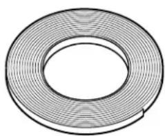
- Foam gasket tape (9 ft. roll)
- Vent grille
- Vent filter
- Cleaning cream
- Scrub sponge or scraper (on some models)

text_image
Sheet Metal Screws (9) (8-18 x 3/8") Hold-Down Retainers and Thumb Screws Vent Grille Cleaning Cream Scrub Sponge Foam Gasket Tape CAUTION: DO NOT LIFT FROM VENT OPENING OR BUMP GLASS CAUTION: GLASS IS FRAGILE DO NOT BUMP EDGE OF GLASS DURING INSTALLATION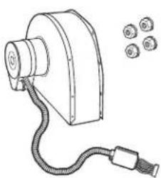
natural_image
Line drawing of a mechanical device with a coiled cable and two circular components (no text or symbols)Blower Assembly and (4) Mounting Nuts (10-32 keps – nuts with lock washers attached)
Blower Plenum
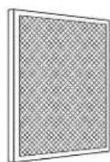
Vent Filter
PREPARATION
TOOLS AND MATERIALS YOU WILL NEED
- Saw
- Flat blade screwdriver
- Electrician's pliers
- Duct tape
- Measuring tape or scale
- Carpenter's square
- 7/16"wrench or socket set
- Drill and drill bit
- Sheet metal screws
- Junction box*
- 3/4"flexible conduit*
• Electrical wire per local code* - Wire nuts*
- Duct work
*NOTE: Electrical installation kit JXCK89 may be ordered separately and includes all the parts necessary to connect the cooktop to typical rough-in wiring.

CAUTION: FOR PERSONAL SAFETY, REMOVE HOUSE FUSE OR CIRCUIT BREAKER BEFORE BEGINNING INSTALLATION.
ELECTRICAL REQUIREMENTS
This appliance must be supplied with the proper voltage and frequency, as listed in these Installation Instructions, and connected to an individual, properly grounded branch circuit, protected by a 40-amp circuit breaker or time delay fuses.
All wire connections must be made in accordance with local codes and properly insulated. Check with your local utility for governing electrical codes and ordinances. In the absence of local electrical codes, the National Electrical Code, ANSI/NFPA No. 70 – Latest Edition, governing electric range installations, must be followed.
A copy of the National Electrical Code can be obtained by writing to:
National Fire Protection Association Batterymarch Park Quincy, MA 02260
Effective January 1, 1996, the National Electrical Code requires that new, but not existing, construction utilize a four-conductor connection to an electric range. When installing an electric range in new construction, follow the instructions in NEW CONSTRUCTION AND FOUR-CONDUCTOR BRANCH CIRCUIT CONNECTION.
You must use a three-wire, single-phase AC 208Y/120 Volt or 240/120 Volt, 60 Hertz electrical system with separate ground. If you connect to aluminum wiring, properly installed connectors approved for use with aluminum wiring must be used.
30"COOKTOP (DIMENSIONS FOR REFERENCE ONLY)
Unit shown fully assembled.
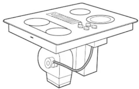
natural_image
Technical line drawing of a mechanical device with mounting base and control panel (no text or symbols)
text_image
21½" - 22" 20½"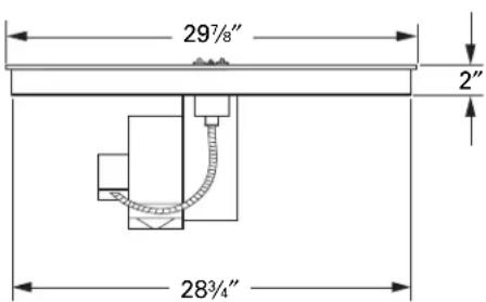
text_image
29½" 2" 28¾"Unit must be vented to the outside!
CABINET PREPARATION
① PREPARING FOR INSTALLATION
Positioning the cooktop
The cooktop is designed to look best when centered in a cabinet at least 30" wide.
The exhaust vent beneath the cooktop must be located between wall studs or floor joists so that the ductwork may be installed properly.
At least 6" must be allowed between side edges of the cooktop and adjacent walls.

text_image
13" max. depth of unprotected overhead cabinets 30" min. clearance from countertop to unprotected overhead surface 15" min. height from countertop to nearest cabinet on either side of the unit 6" min. clearance from cutout to side walls 1½" min.Avoid placing cabinets above the cooktop unit, if possible, in order to reduce the hazards caused by reaching over heated surface units. If cabinets are placed over the cooktop, the risks can be reduced by installing a range hood that projects horizontally a minimum of 5 inches beyond the bottom of the cabinets.
If cabinetry is used above the cooktop, allow a minimum 30" clearance between the cooking surface and the bottom of any unprotected cabinet.
If the clearance between the cooktop and the cabinetry is less than 30", the cabinet bottom must be protected with flame retardant millboard at least 1/4" thick, covered with 28 gauge sheet steel or 0.020" thick copper. Clearance between the cooktop and the protected cabinetry MUST NEVER BE LESS THAN 24."
EXCEPTION: Installation of a listed microwave oven or cooking appliance over the cooktop shall conform to the installation instructions packed with that appliance.
A 15" minimum must be kept from the side edge of the cooktop to the bottom of any cabinet not directly above the cooktop. If the clearance is less than 15", adjacent cabinets should be at least 6" from the side edge of the cooktop.
② PREPARING THE BASE CABINET
This cooktop is designed to fit easily into a variety of cabinets. However, some cabinets may require modifications.
Preparing a cabinet that is against a wall
In some cabinets, the sides may need to be scooped or cut down 5 ^3/4 " as shown, and the corner braces removed in order to accommodate the unit.
In 75 cm and 90 cm frameless European cabinets, the back panel may need to be cut down 5 ^3/4 " to accommodate the unit.
Preparing a peninsula or island-type cabinet
In a peninsula or island-type cabinet, the sides may need to be scooped or cut down, and the corner braces removed in order to accommodate the unit.
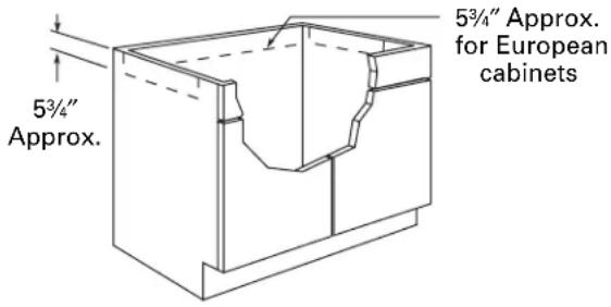
text_image
5¾/4" Approx. Approx. 5¾/4" Approx. for European cabinets③ ROUGH PREPARATION OF JUNCTION BOX
IMPORTANT – FOR PERSONAL SAFETY, REMOVE HOUSE FUSE OR OPEN CIRCUIT BREAKER BEFORE PREPARING JUNCTION BOX.
Install an approved junction box within shaded area shown in diagram. Junction box must be at least 10½" below top of cabinet.
Run conductors from residence wiring to junction box according to local electrical codes.

text_image
16" 9" 4" 20" G 10½"CABINET PREPARATION CUTOUTS
4 PREPARING THE COUNTERTOP
The countertop must have a deep flat surface to accommodate the cooktop and the vent. Countertops with a rolled front edge and backsplash may not provide the flat surface area required.
Clearance between inside front of cabinet and rear of countertop cutout must be 20 ^5/8 " in order to accommodate cooktop depth.

text_image
2¾" Min. 20¾" 1¾" Min.A 1/2" wide flat area is required around the edge of opening for support of the unit. The cooktop unit must be level and sit squarely into countertop opening.
Carefully cut countertop opening according to the dimensions shown in the illustration. Be sure that opening is cut squarely, with sides parallel to each other and rear exactly perpendicular to sides.
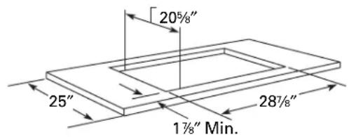
text_image
205/8" 25" 287/8" 17/8" Min.5 PREPARING FOR DUCTWORK
NOTE: Ductwork MUST be vented to outside. DO NOT vent into a wall, ceiling, crawlspace, attic or any concealed space.
Cut hole in cabinet wall or floor as appropriate for your installation. Make sure exhaust duct is located between wall studs or floor joists.
NOTE: When cutting or drilling into wall or ceiling, do not damage electrical wiring and other hidden utilities.
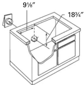
text_image
9½" 18¾/4"Rear Wall Venting
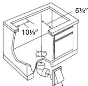
text_image
10½" 6½"Downward Venting
6 BLOWER TO DUCTWORK ALIGNMENT
In general, the use of flexible ducting is discouraged because it can cause severely restricted airflow. However, if the blower outlet and the floor or wall duct location do NOT align well, then flexible METAL ducting can be used to adapt to an offset. Good alignment without use of flexible ducting is best.
NOTE:
- Do not exceed the maximum recommended offset of 6".
- Do not allow the flexible ducting to kink or collapse.
- Do stretch the flexible ducting as much as possible to eliminate as much of the corrugation as possible.

text_image
6" Max. Centerline to Centerline Offset Bottom Venting Back Venting (Requires 3¼" xA 3 ^1/4 " x 10" rectangle to 6" round transition duct is available at your local building supply store.
NOTE: Illustrations are for planning purposes only.
DUCTWORK CALCULATIONS
| Calculate Total Equivalent Ductwork Length | |||
| Duct Pieces Length* x Used = Length | Equivalent Number Equivalent | ||
| 5" round straight 2.7 ft. | x ( ft.) ^ = ft. | ||
| 6" round straight 1 ft. x ( ft.) ^ = ft. | |||
| 31⁄4" x 10" straight 1 ft. x ( ft.) ^ = ft. | |||
| 5", 90° elbow 37 ft. x ( ) = ft. | |||
| 6", 90° elbow 12 ft. x ( ) = ft. | |||
| 5", 45° elbow 18 ft. x ( ) = ft. | |||
| 6", 45° elbow 7 ft. x ( ) = ft. | |||
| Flexible metal offset See Calculations in adapter Step 5A. | ft. | ||
| 31⁄4" x 10" 90° elbow | 14 ft. x ( ) = ft. | ||
| 31⁄4" x 10" 45° elbow | 8 ft. x ( ) = ft. | ||
| 31⁄4" x 10" 90° flat elbow | 33 ft. x ( ) = ft. | ||
| 5" round to 31⁄4" x 10" transition 3 ft. | x ( ) = ft. | ||
| 6" round to 31⁄4" x 10" transition 2 ft. | x ( ) = ft. | ||
| Subtotal Column 1 = ft. | |||
| *Equivalent lengths of duct pieces are based on actual tests and reflect requirements for good venting performance with any downdraft cooktop.†Measure and list feet of straight duct used. Count and list the quantity of all other duct pieces for the "Number Used" of each type.IMPORTANT:For maximum efficiency, use the shortest and straightest duct run possible, with as few fittings as possible.For satisfactory performance, the duct run should not exceed 100 feet equivalent length.Venting performance is improved by using larger diameter duct. | |||
| Duct Pieces Length* x | Equivalent Number Equivalent Used = Length | ||
| 5" round to 31⁄4" x 10" transition90° elbow | 37 ft. x() = ft. | ||
| 6" round to 31⁄4" x 10" transition90° elbow | 4 ft. x() = ft. | ||
| 31⁄4" x 10" to 6" round transition | 2 ft. x() = ft. | ||
| 31⁄4" x 10" to 6" round transition90° elbow | 4 ft. x() = ft. | ft. | |
| Tapered 5" round to 6" round transition | 6 ft. x() = ft. | ft. | |
| 5" round collar to 6" round transition | 13 ft. x() = ft. | ft. | |
| 5" round wall cap with damper | 84 ft. x() = ft. | ||
| 6" round wall cap with damper | 24 ft. x() = ft. | ||
| 31⁄4" x 10" wall cap with damper | 24 ft. x() = ft. | ||
| 6" round roof cap | 33 ft. x() = ft. | ||
| Subtotal Column 2 = ft. | |||
| Subtotal Column 1 = ft. | |||
| TOTAL DUCTWORK = ft. | |||
| Should not exceed 100 feet. | |||
| If flexible metal ducting is used, all the equivalent feet values in the table should be doubled. The flexible metal duct should be straight and smooth and extended as much as possible.DO NOT use flexible plastic ducting.Vent installation should not exceed 100 feet equivalent length.Blower is rated at 400 CFM at 0.1 inch of water back pressure. | |||
EXHAUST BLOWER RATINGS
EXHAUST BLOWER SAFETY WARNING
Sufficient air is needed for proper combustion and exhausting of gases through the flue (chimney) of other fuel burning equipment to prevent back drafting. Follow the heating equipment manufacturer's guidelines and safety standards such as those published by the National Fire Protection Association (NFPA), the American Society for Heating, Refrigeration and Air Conditioning Engineers (ASHRAE) and local code authorities.
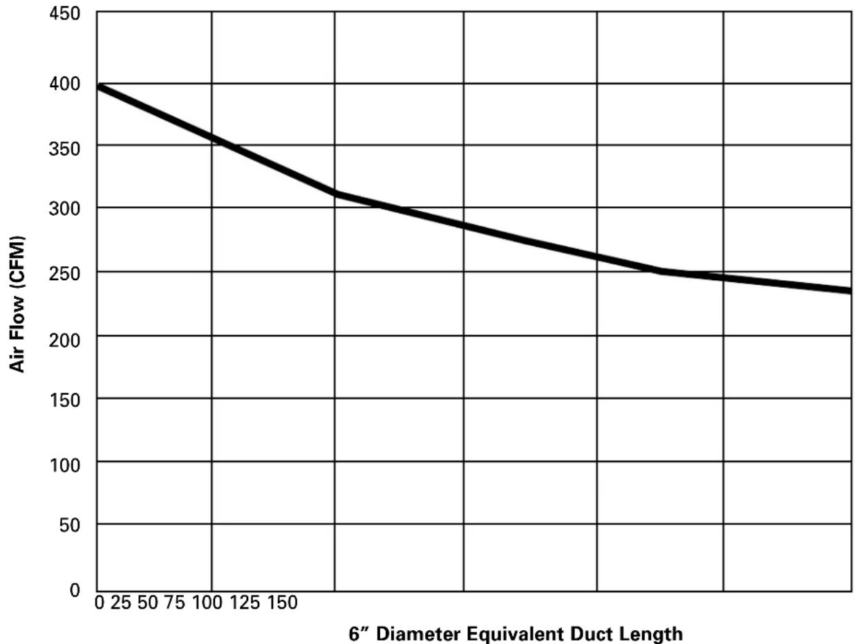
NOTE: The exhaust blower output is approximately 400 CFM (cubic feet per minute) without ductwork. Each installation is different and ductwork affects blower output accordingly. Actual blower exhaust CFM can be approximated using the graph below.
Step 1: Calculate the "equivalent duct length" using the "DUCTWORK CALCULATIONS" table in these instructions for your installation.
Step 2: Find the approximate intersection point of the blower exhaust performance curve with the equivalent duct length to estimate the actual maximum blower output for your installation.
Examples: 50 equivalent feet of ductwork has approximately 320 CFM. 100 equivalent feet of ductwork has approximately 265 CFM.
Downdraft Cooktop Exhaust Blower CFM
line
| 6" Diameter Equivalent Duct Length | Air Flow (CFM) | | ---------------------------------- | -------------- | | 0 | 400 | | 25 | 380 | | 50 | 360 | | 75 | 340 | | 100 | 320 | | 125 | 300 | | 150 | 280 | | 175 | 260 | | 200 | 240 | | 225 | 230 | | 250 | 220 | | 275 | 210 | | 300 | 200 | | 325 | 190 | | 350 | 180 | | 375 | 170 | | 400 | 160 | | 425 | 150 | | 450 | 140 | | 475 | 130 | | 500 | 120 | | 525 | 110 | | 550 | 100 | | 575 | 90 | | 600 | 80 | | 625 | 70 | | 650 | 60 | | 675 | 50 | | 700 | 40 | | 725 | 30 | | 750 | 20 | | 775 | 10 | | 800 | 5 | | 825 | 3 | | 850 | 2 | | 875 | 1 | | 900 | 1 | | 925 | 1 | | 950 | 1 | | 975 | 1 | | 1000 | 1 |DUCTWORK INSTALLATION
(Note: For planning purposes only.)
⑦ INSTALLING THE DUCTWORK
Use galvanized or aluminum duct in 6" round or 3 ^1/4 " x 10" size, or a combination of both.
PVC duct should be used if installing under a poured concrete slab.
NOTE: Local building code must be followed in specifying approved type and schedule of ALL duct used.
Always use an appropriate roof or wall cap with damper. Laundry-type wall caps should NEVER be used.
natural_image
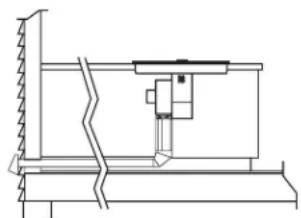
Technical line drawing of a mechanical assembly or structural component (no text or symbols visible)Through Cabinet Toe Space Between Floor Joist
Downward Venting
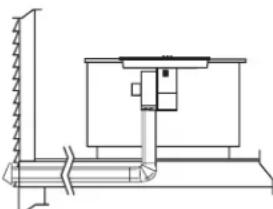
natural_image
Technical line drawing of a mechanical assembly with no visible text or symbolsInstall ductwork, making male-female connections in the direction of airflow as shown. Secure all joints with sheet metal screws and duct tape to assure an airtight seal.
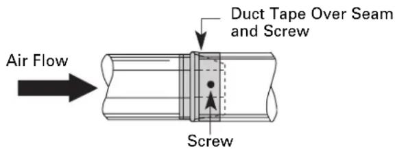
text_image
Air Flow Duct Tape Over Seam and Screw ScrewUse the shortest and straightest duct run possible. For satisfactory performance, the duct run should not exceed 100 feet equivalent length. Refer to TABLE 1 of equivalent lengths. Use TABLE 1 to calculate the total equivalent length of the ductwork.
OPTIONAL INSTALLATION: REAR WALL VENTING
5" round duct may be used on SHORT DUCT runs but best results will be obtained using 3 14 " x 10" or 6" round ducting.
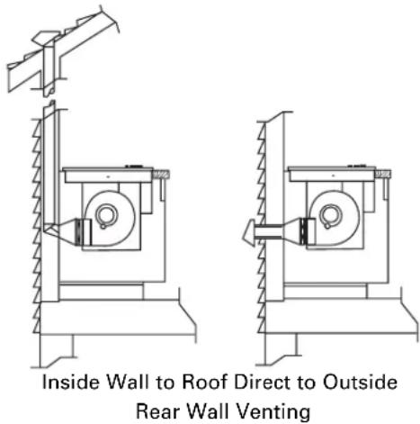
text_image
Inside Wall to Roof Direct to Outside Rear Wall VentingTo convert blower exhaust direction, remove four nuts behind the filter which hold blower and wire finger guard.
Rotate blower and reinstall to vent chamber, as shown above. Retighten nuts, but do not overtighten.
UNPACKING THE COOKTOP/INSTALLING THE GASKET
8 INSTALLING THE FOAM GASKET
Do not install the cooktop into the countertop without installing the foam gasket as shown. It protects the bottom edge of the glass from the countertop and seals the cooktop against spills.
Remove the cooktop along with its shipping pad from the shipping box. Remove the shipping block from the downdraft vent opening and place it under the shipping pad to provide level support.

natural_image
Technical line drawing of a mechanical component with no visible text or symbolsCenter vent shipping block – place under the shipping pad to provide level support
⚠️ CAUTION: GLASS IS FRAGILE. DO NOT BUMP EDGE OF GLASS DURING INSTALLATION.
Locate the foam gasket tape included with your cooktop.
natural_image
Circular mechanical component with concentric grooves and a central hole (no text or symbols)Peel off the white backing to install the foam gasket tape on the bottom side of the cooktop glass as shown.
Foam Gasket Installation Notes:
- The foam gasket tape should be installed within 1/8" of the edge of the glass. Do not stretch or twist the foam gasket tape.
⚠️ CAUTION: Failure to install foam gasket tape greatly increases the potential of breaking the cooktop glass when installing, especially in Corian® or granite countertops.
- Use care not to stretch the foam gasket tape while it is installed or it will not stay in place.
- Do not place foam gasket tape over the metal flanges.
- Butt the foam gasket tape ends together at each corner without overlapping.
- Trim the foam gasket tape to length without stretching.
- Mitre cut outside corners of foam gasket tape slightly if necessary for appearance.
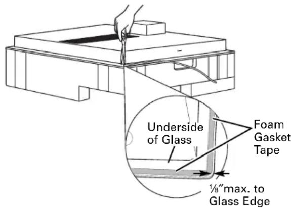
text_image
Underside of Glass Foam Gasket Tape ½" max. to Glass Edge- Do not scratch the glass while cutting the foam gasket tape.
INSTALLING THE COOKTOP
⑨ INSTALLING THE COOKTOP

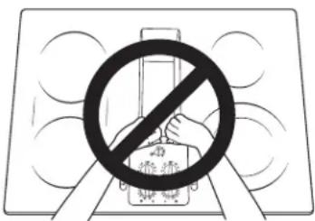
text_image
Safety warning symbol with crossed-out circle and hand holding a device, indicating no hazard or cautionCAUTION:
DO NOT LIFT FROM VENT OPENING.
Lift the cooktop by the glass side edges as shown.
NOTE: Do not use the glass top vent opening to lift or move the cooktop into position.
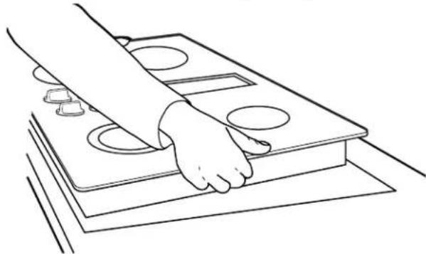
natural_image
Line drawing of a hand pressing down on a wooden table with circular cutouts (no text or symbols)Lower the cooktop into the countertop opening, guiding it into position. Glass is fragile—do not allow it to drop onto the countertop. Support from the underside and lower slowly.
Carefully remove your fingers one corner at a time to lower the cooktop into position.
NOTE: Do not use Silicone RTV or caulk to bond cooktop glass to countertop.
10 CHECKING FOR FLATNESS
Inspect the cooktop glass for rocking or uneven gap on all four sides at the countertop surface. Do not attempt to force the glass to meet the countertop.
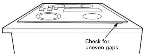
text_image
Check for uneven gapsINSTALLING THE COOKTOP
11 INSTALLING THE HOLD-DOWN RETAINERS
NOTE: Check for glass flatness in Step 10 before installing hold-down retainers.

text_image
Hold-down retainer Hold-down retainer Countertop Thumb screwSecure cooktop to the counter using the hold-down retainers and thumb screws shipped with the unit (one on each side).
12 INSTALLING THE BLOWER PLENUM TO THE COOKTOP
Slide the plenum, with the blower opening on the left, into the opening in the bottom of the cooktop. Push up on the plenum until the stops on the plenum contact the bottom of the cooktop, and snap the plenum into place. (You may have to move the plenum back and forth to work it into place.)
natural_image
Line drawing of a washing machine with a door and vent, showing airflow direction (no text or symbols)Secure the plenum to the bottom of the cooktop, on each side, using the four (4) screws provided. Further secure the plenum to the cooktop, from the top side, using the two screws (2) provided.
13 INSTALLING THE BLOWER TO THE PLENUM
Orient the blower discharge opening to match the ductwork in Steps 6 and 7. Slide the four threaded studs on the side of the blower housing into the four holes on the side of the plenum.
NOTE: See Step 14 for installing the transition duct to the blower. It may be easier to install the transition duct to the blower before installing the blower to the plenum.
natural_image
Technical line drawing of a mechanical device with a coiled cable and mounting base (no text or symbols)From the vent opening in the top of the cooktop, fasten the blower assembly securely to the plenum with four (4) nuts.

text_image
4 Nuts (7/16" socket required)INSTALLING THE COOKTOP
14 ATTACHING A BLOWER TRANSITION DUCT
Use a blower transition duct for all downward duct installations to connect to 6"round standard ductwork. This 3 ^1/4 " x 10" rectangle to 6"round transition duct is available at your local building supply store.

text_image
Screws Screw (on other side)Remove the cardboard packing in the blower outlet.
Install the transition duct to the blower outlet. Secure all joints with duct tape to assure an airtight seal.
15 CONNECTING THE DUCTWORK
Connect the ductwork prepared in Steps 5 and 6 to the blower transition duct.
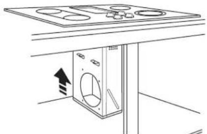
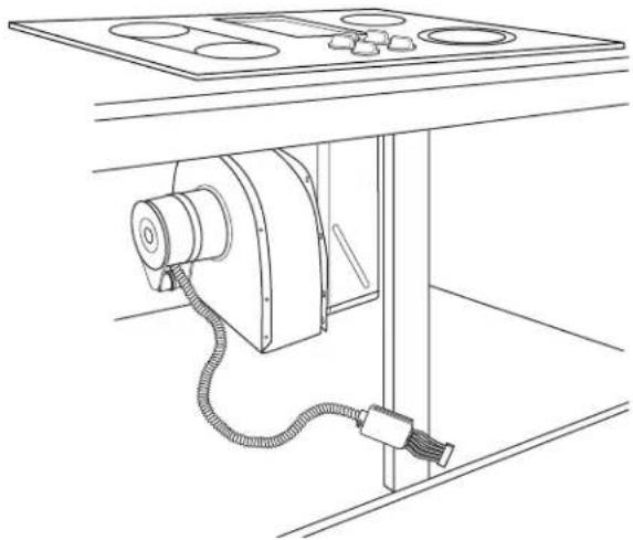
16 BLOWER ELECTRICAL CONNECTIONS
- Loosen the screws and remove and discard the sheet metal strap covering the 5-pin connector. Save the screws for reinstallation later.
- Connect the 5-pin plug on the blower assembly to the matching 5-pin receptacle on the bottom of the wire enclosure.
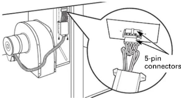
text_image
5-pin connectors- Fold all wires into the electrical enclosure. Secure the enclosure with the screws removed earlier, making sure that no wires are trapped.
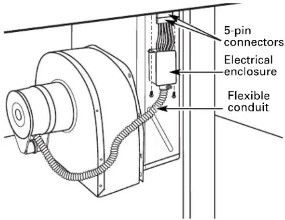
text_image
5-pin connectors Electrical enclosure Flexible conduitELECTRICAL CONNECTIONS
17 BEFORE MAKING ELECTRICAL CONNECTIONS
Note to Electrician: The power leads supplied with this appliance are UL-recognized for connection to large gauge household wiring.
The insulation of these leads is rated at temperatures much higher than the temperature rating of household wiring. The current carrying capacity of a conductor is governed by the wire gauge and also the temperature rating of the insulation around the wire.
Aluminum Wiring – WARNING: IMPROPER CONNECTION OF ALUMINUM HOUSE WIRING TO THE COPPER LEADS CAN RESULT IN SERIOUS PROBLEMS.
Attach copper wires to aluminum wiring using special connectors designed and UL-listed for joining copper to aluminum. Follow the connector manufacturer's recommended procedure closely.
Service Loop – Leave a loop in the wires to the cooktop so that the cooktop can be lifted 12 inches without having to disconnect the wiring.
ELECTRICAL REQUIREMENTS\*
Model # Voltage Frequency KW
JP989 120/240V 60Hz 8.8KW
120/208V 60Hz 6.7KW
*For reference only. Verify with product rating plate.

text_image
Rating Plate18 INSTALL 3/4"FLEXIBLE CONDUIT
Remove the screws holding the wire compartment cover and remove the cover.

18 INSTALL 3/4"FLEXIBLE CONDUIT (cont.)
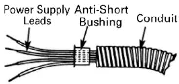
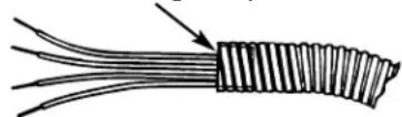
Feed the power supply leads through the conduit; be sure to leave enough length to properly connect these leads to the cooktop power leads.
Thread the leads through an anti-short bushing and firmly seat the bushing in the end of the conduit.
Feed the leads through the hole in the wire compartment.
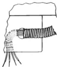
As local codes permit purchase a listed conduit connector suitable for the size conduit. Insert the conduit through the connector and attach it to the cover. Allow enough slack to easily attach the wires to the cooktop.
Note: Do not install the cooktop without a listed conduit connector.
The conduit connector should be installed before reinstalling the wiring cover.
When complete, reinstall the wire compartment cover.
text_image
Power Supply Leads Anti-Short Bushing ConduitBushing (Fully Seated)
natural_image
Diagram of a mechanical or electrical component with no visible text, numbers, or symbols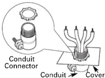
text_image
Conduit Connector Conduit CoverELECTRICAL CONNECTIONS
19 MAKING ELECTRICAL CONNECTIONS
Effective January 1, 1996, the National Electrical Code requires that new, but not existing, construction utilize a four-conductor connection to an electric range. When installing an electric range in new construction, follow the instructions in NEW CONSTRUCTION AND FOUR-CONDUCTOR BRANCH CIRCUIT CONNECTION.
You must use a three-wire, single-phase AC 208Y/120 Volt or 240/120 Volt, 60 Hertz electrical system with separate ground. If you connect to aluminum wiring, properly installed connectors approved for use with aluminum wiring must be used.
New construction and four-conductor branch circuit connection
- When installing in new construction, or
- When installing in a mobile home, or
- When local codes do not permit grounding through neutral:
4-Conductor Branch Circuit
When connecting the cooktop to a 4-conductor circuit, connect the red leads of the cooktop and the power supply to the branch circuit red lead; connect the black leads to each other. Connect the cooktop white lead to the power supply and branch circuit neutral leads, which are white or gray. Ground the unit by connecting the green conductor of the cooktop to the bare or green leads of the power supply and branch circuit (ground leads).
4-Conductor Branch Circuit

flowchart
graph TD
    A["Branch Circuit Power Supply Leads"] --> B["Cooktop Power Leads"]
    C["Red Red Red"] --> D["White or Gray"]
    E["White or Gray White"] --> F["Black Black Black"]
    G["Bare or Green"] --> H["Bare or Green Green"]
    I["GND"] --> J["Bare or Green"]
    K["120V AC"] --> L["NEUTRAL"]
    M["120V AC"] --> N["GND"]
19 MAKING ELECTRICAL CONNECTIONS (cont.)
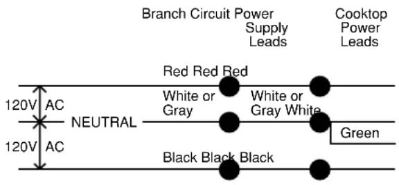
Three-conductor branch circuit connection
- When installing in existing construction built prior to January 1, 1996, and if permitted by local codes:
3-Conductor Branch Circuit
When connecting cooktop to a 3-conductor circuit, connect the red leads of the cooktop and the power supply to the branch circuit red lead; connect the black leads to each other. Connect the green and white leads of the cooktop to the power supply and branch circuit neutral leads, which are white or gray.
3-Conductor Branch Circuit
text_image
Branch Circuit Power Supply Leads Cooktop Power Leads Red Red Red White or Gray White or Gray White NEUTRAL Green 120V AC 120V AC Black Black BlackFINAL ASSEMBLY
20 INSTALL DOWNDRAFT FILTER AND VENT GRILLE
Do not operate the vent without the filter in place.
- Place the filter diagonally through the vent opening.

text_image
Vent Filter Vent Chamber- Make sure it rests, at an angle, on the supports in the vent opening.
natural_image
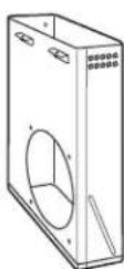
Simple line drawing of a 3D rectangular object with a mesh pattern on its surface, enclosed in a corner frame (no text or symbols)- Carefully place the vent grille onto the downdraft opening.
CHECK OPERATION OF DOWNDRAFT
- Turn the vent fan speed control to HI, MED and LO to make sure all speeds operate correctly.
Before you call for service...
Troubleshooting Tips—Save time and money! Review this chart first and you may not need to call for service.
Problem Possible Causes What To Do
| Water won't boil | • Cover pan with a lid.• Turn the downdraft fan OFF until the water begins to boil. | |
| Surface units will not maintain a rolling boil or cooking is slow | Improper cookware being used. | • Pan bottoms should be flat, fairly heavyweight and the same diameter as the surface unit selected. |
| Surface units do not work properly be blown or the circuit breaker tripped. | A fuse in your home may or the circuit breaker tripped. | • Replace the fuse or reset the circuit breaker. |
| Cooktop controls improperly set. | • Check to see the correct control is set for the surface unit you are using. | |
| Tiny scratches or metal marks (may appear as cracks) or abrasions on radiant cooktop glass surface | Incorrect cleaning methods being used. | • See the Cleaning the glass cooktop section. |
| Cookware with rough bottoms being used or coarse particles (salt or sand) were between the cookware and the surface of the cooktop. | • Be sure cookware bottoms and cookware are clean before use. Use cookware with smooth bottoms. Tiny scratches are not removable but will become less visible in time as a result of cleaning. | |
| Cookware has been slid across the cooktop surface. | ||
| Areas of discoloration or dark streaks on the cooktop | Improper cookware being used. | • Marks from aluminum and copper pans as well as mineral deposits from water or food can be removed with the cleaning cream. |
| Hot surface on a model with a light-colored cooktop. | • This is normal. The surface may appear discolored when it is hot. This is temporary and will disappear as the glass cools. | |
| Hot sugar mixtures or plastic melted into contact with to the surface | Hot cooktop came these substances. | • See the Cleaning the glass cooktop section. |
| Frequent cycling off and on of surface units | Improper cookware being used. | • Use only flat cookware to minimize cycling. |
| Cooktop feels hot | Improper cookware being used. are used to. This is normal. Use pans which are absolutely flat. | • The glass cooktop surface may seem hotter than you |
| Control knob will not turn | Cooktop controls improperly set. | • When the knob is in the OFF position, it must be pushed down before it can be turned. When the knob is in any other position, it can be turned without being pushed in. |
| Poor venting | Clogged filter.House too airtight.Wall cap obstructed.Wall cap damper door stuck.Duct length exceeds recommended 100 equivalent foot maximum. | • Clean filter per instructions.• Open a window slightly to provide fresh air source.• Remove blockage from exterior wall cap.• Check exterior wall cap damper door for free movement or obstruction.• Reduce number of elbows to simplify duct run. |
GE Service Protection Plus™
GE, a name recognized worldwide for quality and dependability, offers you Service Protection Plus™—comprehensive protection on all your appliances—No Matter What Brand!
Benefits Include:
- Backed by GE
- All brands covered
• Unlimited service calls - All parts and labor costs included
• No out-of-pocket expenses
• No hidden deductibles
• One 800 number to call
We'll Cover Any Appliance. Anywhere. Anytime.\*
You will be completely satisfied with our service protection or you may request your money back on the remaining value of your contract. No questions asked. It's that simple.
Protect your refrigerator, dishwasher, washer and dryer, range, TV, VCR and much more—any brand! Plus there's no extra charge for emergency service and low monthly financing is available. Even icemaker coverage and food spoilage protection is offered. You can rest easy, knowing that all your valuable household products are protected against expensive repairs.
Place your confidence in GE and call us in the U.S. toll-free at 800.626.2224 for more information.
*All brands covered, up to 20 years old, in the continental U.S.

Cut here
Please place in envelope and mail to:
General Electric Company
Warranty Registration Department
P.O. Box 32150
Louisville, KY 40232-2150
Consumer Product Ownership Registration
Dear Customer:
Thank you for purchasing our product and thank you for placing your confidence in us.
We are proud to have you as a customer!
Follow these three steps to protect your new appliance investment:
1
Complete and mail your Consumer
Product Ownership Registration today.
Have the peace of mind of knowing we can contact you in the unlikely event of a safety modification.
2
After mailing the registration below, store this document in a safe place. It contains information you will need should you require service. Our service number is 800.GE.CARES (800.432.2737).
3
Read your Owner's
Manual carefully.
It will help you
operate your new
appliance properly.
Model Number Serial Number

natural_image
Two identical horizontal lines with tick marks, no text or symbols presentImportant: If you did not get a registration card with your product, detach and return the form below to ensure that your product is registered, or register online at ge.com.

Consumer Product Ownership Registration

Model Number Serial Number

natural_image
Two identical horizontal lines with tick marks, no text or symbols present
text_image
Mr. □ Ms. □ Mrs. □ Miss _ First Name Last Name
text_image
Street Address
text_image
Apt. # E-mail Address* _
text_image
City State Zip Code
text_image
Date Placed In Use Month Day Year Phone Number
GE Consumer & Industrial
Appliances
General Electric Company
Louisville, KY 40225
ge.com
* Please provide your e-mail address to receive, via e-mail, discounts, special offers and other important communications from GE Appliances (GEA).
□ Check here if you do not want to receive communications from GEA's carefully selected partners.
FAILURE TO COMPLETE AND RETURN THIS CARD DOES NOT DIMINISH YOUR WARRANTY RIGHTS.
For information about GEA's privacy and data usage policy, go to ge.com and click on "Privacy Policy" or call 800.626.2224.
GE Electric Cooktop Warranty.

All warranty service provided by our Factory Service Centers, or an authorized Customer Care® technician. To schedule service, on-line, visit us at ge.com, or call 800.GE.CARES (800.432.2737). Please have serial number and model number available when calling for service.
Staple your receipt here. Proof of the original purchase date is needed to obtain service under the warranty.
For The Period Of: GE Will Replace:
| One YearFrom the date of the original purchase replace the defective part. | Any part of the cooktop which fails due to a defect in materials or workmanship. During this limited one-year warranty, GE will also provide, free of charge, all labor and in-home service to |
| Five YearsFrom the date of the pattern wears off. | A replacement glass cooktop if it should: crack due to thermal shock; discolor; or if the |
| original purchase | A replacement radiant surface unit if it should burn out.During this limited additional four-year warranty, you will be responsible for any labor or in-home service. |
What GE Will Not Cover:
■ Service trips to your home to teach you how to use the product.
- Improper installation, delivery or maintenance.
Failure of the product if it is abused, misused, or used for other than the intended purpose or used commercially.
■ Damage to the glass cooktop caused by use of cleaners other than the recommended cleaning creams and pads.
Damage to the glass cooktop caused by hardened spills of sugary materials or melted plastic that are not cleaned according to the directions in the Owner's Manual.
■ Replacement of house fuses or resetting of circuit breakers.
■ Damage to the product caused by accident, fire, floods or acts of God.
■Incidental or consequential damage caused by possible defects with this appliance.
■ Damage caused after delivery.
■ Product not accessible to provide required service.
EXCLUSION OF IMPLIED WARRANTIES—Your sole and exclusive remedy is product repair as provided in this Limited Warranty. Any implied warranties, including the implied warranties of merchantability or fitness for a particular purpose, are limited to one year or the shortest period allowed by law.
This warranty is extended to the original purchaser and any succeeding owner for products purchased for home use within the USA. If the product is located in an area where service by a GE Authorized Servicer is not available, you may be responsible for a trip charge or you may be required to bring the product to an Authorized GE Service Location for service. In Alaska, the warranty excludes the cost of shipping or service calls to your home.
Some states do not allow the exclusion or limitation of incidental or consequential damages. This warranty gives you specific legal rights, and you may also have other rights which vary from state to state. To know what your legal rights are, consult your local or state consumer affairs office or your state's Attorney General.
GE Appliances Website
ge.com
Have a question or need assistance with your appliance? Try the GE Appliances Website any day of the year! For greater convenience and faster service, you can now download Owner's Manuals, order parts or even schedule service on-line.
Schedule Service ge.com
Expert GE repair service is only one step away from your door. Get on-line and schedule your service at your convenience 24 hours any day of the year! Or call 800.GE.CARES (800.432.2737) during normal business hours.
Real Life Design Studio ge.com
GE supports the Universal Design concept—products, services and environments that can be used by people of all ages, sizes and capabilities. We recognize the need to design for a wide range of physical and mental abilities and impairments. For details of GE's Universal Design applications, including kitchen design ideas for people with disabilities, check out our Website today. For the hearing impaired, please call 800.TDD.GEAC (800.833.4322).

Extended Warranties ge.com
Purchase a GE extended warranty and learn about special discounts that are available while your warranty is still in effect. You can purchase it on-line anytime, or call 800.626.2224 during normal business hours. GE Consumer Home Services will still be there after your warranty expires.
Parts and Accessories ge.com
Individuals qualified to service their own appliances can have parts or accessories sent directly to their homes (VISA, MasterCard and Discover cards are accepted). Order on-line today, 24 hours every day or by phone at 800.626.2002 during normal business hours.
Instructions contained in this manual cover procedures to be performed by any user. Other servicing generally should be referred to qualified service personnel. Caution must be exercised, since improper servicing may cause unsafe operation.

Contact Us ge.com
If you are not satisfied with the service you receive from GE, contact us on our Website with all the details including your phone number, or write to: General Manager, Customer Relations
GE Appliances, Appliance Park
Louisville, KY 40225
Register Your Appliance ge.com
Register your new appliance on-line—at your convenience! Timely product registration will allow for enhanced communication and prompt service under the terms of your warranty, should the need arise. You may also mail in the pre-printed registration card included in the packing material.
Estufa
text_image
Diagram of a home control panel with labeled components including a 3-pin heater and a rotary switch.text_image
OFF HI MED LOnatural_image
Simple line drawing of a hand using a ruler to press a rectangular object (no text or symbols)text_image
Three identical cooking pots with black X-shaped symbols, likely indicating prohibition or resistance.natural_image
Diagram of a mesh panel inside a container, labeled '防雷黑玻璃' (no other text or symbols)natural_image
Hand using a tool to press small objects on a circular surface (no text or symbols visible)natural_image
Hand using a brush to clean or store food on an induction cooktop (no text or symbols visible)natural_image
Line drawing of a rectangular object with vertical striped pattern and a small circular hole (no text or symbols)text_image
Diagram showing a prohibition symbol over a device with labeled parts and text, likely indicating a prohibition or prohibition in a technical or educational context.natural_image
Line drawing of a rectangular appliance with circular cutouts and a base, showing internal components and directional arrows (no text or symbols)natural_image
Line drawing of a mechanical device with a coiled cable and two circular components (no text or symbols)National Fire Protection Association
Batterymarch Park
Quincy, MA 02260
natural_image
Technical line drawing of a mechanical device with mounting base and control panel (no text or symbols)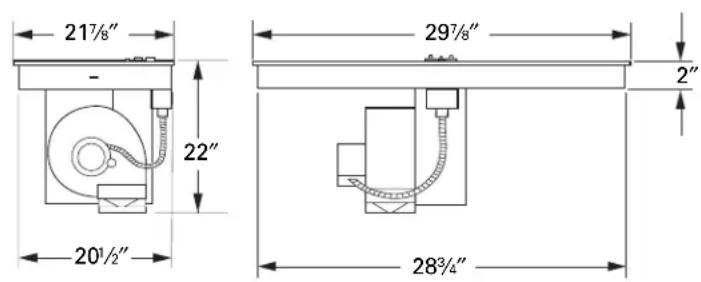
text_image
21½" - 22" 20½" 29½" 2" 28¾"text_image
16" 9" 4" 20" 10½"text_image
205/8" 25" 287/8" 17/8" Min.natural_image
Technical line drawing of a mechanical assembly or structural component (no text or symbols visible)natural_image
Technical line drawing of a mechanical assembly with no visible text or symbolsnatural_image
Technical line drawing of a mechanical assembly with gear and housing (no text or symbols)natural_image
Technical line drawing of a mechanical assembly with gears and housing (no text or symbols)⑧ CÓMO INSTALAR LA JUNTA DE ESPUMA
natural_image
Technical line drawing of a mechanical housing or enclosure with internal components and a directional arrow (no text or symbols)natural_image
Circular mechanical component with concentric grooves and a central hole (no text or symbols)CÓMO INSTALAR LA ESTUFA
9 CÓMO INSTALAR LA ESTUFA
text_image
修缮natural_image
Line drawing of a hand pressing down on a wooden table with circular cutouts (no text or symbols)CÓMO INSTALAR LA ESTUFA
11 INSTALE LAS RETENEDORAS
natural_image
Line drawing of a kitchen appliance with a hanging fan and door, showing no text or symbolsnatural_image
Line drawing of a mechanical device with a coiled cable and mounting base (no text or symbols)natural_image
Diagram of a mechanical or electrical component with internal structure and no visible text or symbols
natural_image
Diagram of a mesh panel inside a container, no text or symbols presentGeneral Manager, Customer Relations
GE Appliances, Appliance Park
Louisville, KY 40225