
L7S7A - Tablet ECS - Free user manual and instructions
Find the device manual for free L7S7A ECS in PDF.

| Product Type | Desktop motherboard |
| Form Factor | ATX (standard estimate) |
| Processor Socket | Socket A (AMD 462 pins) |
| Supported Processors | AMD Athlon/Duron with FSB 133/166 MHz |
| Chipset | SiS746 + SiS963/963L Southbridge |
| RAM Memory | DDR SDRAM 200/266/333 MHz, up to 3 GB (3 DIMM slots) |
| Graphics Slot | 1 AGP 8x slot (1.5 V only) |
| Expansion Slots | 5 PCI 32-bit, 1 CNR (AC97) |
| Storage | 2 IDE connectors (4 devices), 1 floppy drive, optional Serial ATA 2 channels |
| Audio | AC'97 2.2 codec, line in/out, microphone |
| Network | Integrated Fast Ethernet 10/100 Mbps LAN (Realtek RTL8100B) |
| USB Connectors | 6 USB 2.0 ports (2 front, 4 via internal connectors) |
| IEEE 1394 Connectors | Optional (via integrated controller for SiS963) |
| Rear I/O Ports | 2 PS/2, 2 serial, 1 parallel, 1 MIDI/game, 2 USB, 1 LAN, 3 audio jacks |
| BIOS | AMI BIOS with power management and CPU/memory settings |
| Package Contents | Motherboard, IDE and floppy cables, driver CD, I/O shield, retention module, manual |
| Maintenance and Cleaning | Regular dusting, avoid moisture, use an antistatic cloth |
| Safety | Discharge static electricity before handling, disconnect power |
| Spare Parts and Repairability | Standard components, capacitors and connectors replaceable by a technician |
Frequently Asked Questions - L7S7A ECS
Check BIOS compatibility for newer models.
Supported frequencies are 200, 266 and 333 MHz.
Check your graphics card voltage before installation.
Restart and follow the on-screen instructions.
Make sure the main ATX connector is compatible.
You can also disable onboard audio in the BIOS if you install a dedicated sound card.
Return the jumper to its normal position, reconnect, and restart.
User questions about L7S7A ECS
0 question about this device. Answer the ones you know or ask your own.
Ask a new question about this device
Download the instructions for your Tablet in PDF format for free! Find your manual L7S7A - ECS and take your electronic device back in hand. On this page are published all the documents necessary for the use of your device. L7S7A by ECS.
USER MANUAL L7S7A ECS
This publication, including all photographs, illustrations and software, is protected under international copyright laws, with all rights reserved. Neither this manual, nor any of the material contained herein, may be reproduced without written consent of the author.
Version 1.0
Disclaimer
The information in this document is subject to change without notice. The manufacturer makes no representations or warranties with respect to the contents hereof and specifically disclaims any implied warranties of merchantability or fitness for any particular purpose. The manufacturer reserves the right to revise this publication and to make changes from time to time in the content hereof without obligation of the manufacturer to notify any person of such revision or changes.
Trademark Recognition
Microsoft, MS-DOS and Windows are registered trademarks of Microsoft Corp.
MMX, Pentium, Pentium-II, Pentium-III, Celeron are registered trademarks of Intel Corporation.
Other product names used in this manual are the properties of their respective owners and are acknowledged.
Federal Communications Commission (FCC)
This equipment has been tested and found to comply with the limits for a Class B digital device, pursuant to Part 15 of the FCC Rules. These limits are designed to provide reasonable protection against harmful interference in a residential installation. This equipment generates, uses, and can radiate radio frequency energy and, if not installed and used in accordance with the instructions, may cause harmful interference to radio communications. However, there is no guarantee that interference will not occur in a particular installation. If this equipment does cause harmful interference to radio or television reception, which can be determined by turning the equipment off and on, the user is encouraged to try to correct the interference by one or more of the following measures:
- Reorient or relocate the receiving antenna.
- Increase the separation between the equipment and the receiver.
- Connect the equipment onto an outlet on a circuit different from that to which the receiver is connected.
- Consult the dealer or an experienced radio/TV technician for help.
Shielded interconnect cables and a shielded AC power cable must be employed with this equipment to ensure compliance with the pertinent RF emission limits governing this device. Changes or modifications not expressly approved by the system's manufacturer could void the user's authority to operate the equipment.
Declaration of Conformity
This device complies with part 15 of the FCC rules. Operation is subject to the following conditions:
- This device may not cause harmful interference, and
This device must accept any interference received, including interference that may cause undesired operation.
Canadian Department of Communications
This class B digital apparatus meets all requirements of the Canadian Interference-causing Equipment Regulations.
The manual consists of the following:
Chapter 1 Introducing the Mainboard Describes features of the mainboard, and provides a shipping checklist.
Go to page 1
Chapter 2 Describes installation of mainboard components. Installing the Mainboard
Go to page 8
Chapter 3 Using BIOS Provides information on using the BIOS Setup Utility.
Go to page 28
Chapter 4 Describes the mainboard software. Using the Mainboard Software Go to page 43
Features and Packing List Translations
Liste de contrôle
Features and Packing List Translations iii
CHAPTER 1 1
Introducing the Mainboard 1
Introduction....1
Checklist 2
Standard Items 2
Features 3
Choosing a Computer Case ....5
Mainboard Components ....6
CHAPTER 2 8
Installing the Mainboard 8
Safety Precautions....8
Quick Guide....8
Installing the Mainboard in a Case....9
Checking Jumper Settings....9
Setting Jumpers 9
Checking Jumper Settings 10
Jumper Settings 10
Connecting Case Components....12
Front Panel Connector....14
Installing Hardware 15
Installing the Processor.... 15
Installing Memory Modules 17
Installing a Hard Disk Drive/CD-ROM....18
Installing a Floppy Diskette Drive.... 20
Installing Add-on Cards....21
Connecting Optional Devices....23
Connecting I/O Devices 26
External Connector Color Coding 27
CHAPTER 3 28
Using BIOS 28
About the Setup Utility 28
The Standard Configuration 28
Running the Setup Utility 29
Using BIOS....30
Standard CMOS Setup....30
Advanced CMOS Setup.... 31
Advanced Chipset Setup.... 33
Power Management Setup 35
PCI / Plug and Play Setup.... 37
Peripheral Setup 38
Hardware Monitor Page.... 40
Change Supervisor/User Password.... 41
Auto Configuration with Optimal Settings 42
Auto Configuration with Fail Safe Settings.... 42
Save Settings and Exit 42
Exit Without Saving 42
CHAPTER 4 43
Using the Mainboard Software 43
About the Software CD-ROM 43
Auto-installing under Windows 98/ME/2000/XP 43
Running Setup 44
Manual Installation....45
Utility Software Reference 46
Introduction
Thank you for choosing the L7S7A mainboard. The L7S7A is designed to fit the advanced AMD processors in the 462-pin package. Based on the ATX form factor featuring the SiS746 Northbridge and SiS963/963L Southbridge chipsets. This mainboard provides the standard 133/166MHz front side bus with for high-end business or personal desktop markets.
The mainboard incorporates the SiS746 Northbridge and SiS963 Southbridge chipsets. The SiS746 Northbridge features the S2K complaint bus driver technology to support AMD 133/166 MHz FSB processor. It also supports the AMD PowerNow!™ dynamic power management technique. The Memory Controller can support DDR and offer bandwidth up to 2.7GB/s under DDR333 in order to sustain the bandwidth demand from host processor, as well as the multi I/O masters and AGP masters. While the SiS963/963L Southbridge integrates the Universal Serial Bus 2.0 Host Controllers, 1394a (except for SiS963L) and Audio Controller with AC 97 interface.
The L7S7A is designed to give customers an advanced, multimedia solution at a very low cost. It provides advanced full set of I/O ports, such as dual channel IDE interfaces, a floppy controller, two high-speed serial port, an EPP/ECP capable bi-directional parallel port connector, four USB (Universal Serial Bus) connector, a PS/2 keyboard, mouse and 1394a connectors. One AGP slot, five PCI local bus slots and one communication and networking riser (CNR) slot provide expandability for add-on peripheral cards.
Note: SDRAM provides 800 MBps or 1 GBps data transfer depending on whether the bus is 100 MHz or 133 MHz. Double Data Rate SDRAM (DDR SDRAM) doubles the rate to 1.6 GBps or 2.7 GBps by transferring data on both the rising and falling edges of the clock. DDR SDRAM uses additional power and ground lines and requires 184-pin DIMM modules rather than the 168-pin DIMMs used by SDRAM.
Checklist
Compare the mainboard's package contents with the following checklist:
Standard Items
- One mainboard
• One diskette drive ribbon cable
• One IDE drive ribbon cable
• One auto-install software support CD - One I/O panel
• This user's manual
Features
| Processor The mainboard uses an AMD 462-pin Socket A that supports 133/166 MHz frontside bus (FSB). | |
| Chipset The SiS746 and SiS963/963L chipsets are based on an innovative and scalable architecture with proven reliability and performance. A few of the chipset's advanced features are:Supports AMD Socket A CPU: 133/166 MHzSynchronous/Asynchronous Host-t-DRAM timing: 133/200, 133/266, 133/333, 166/266, 166/333Supports 200/266/333 DDR SDRAMSupports up to 2 unbuffered DIMM DDR333 or up to 3 unbuffered double-sided DIMM DDR266/200AGP v3.0 CompliantBi-directional 16 bit data bus1 GB/s performance in 133MHz x 4 modePCI 2.2 Specification ComplianceIntegrated Multithreaded I/O Link Mastering with Read Pipelined StreamingSupports Enhanced Software and Automatic schemes to access PHY registersSupports Ultra DMA 33/66/100/133USB v2.0 and Enhanced Host Controller Interface (EHCI) v1.0 compatibleAdditional key features include support for six USB ports, Fast Ethernet MAC controller, AC97 interface, IEEE 1394 host controller (except for SiS963L Southbridge chipset), advanced power management, integrated DMA controller and keyboard controller. | |
| Memory | Supports DDR up to 200/266/333 MHz SDRAM memory moduleAccommodates three unbuffered 2.5V 184-pin slotsEach slot supports up to 1 GB with a total maximum capacity of 3 GB |
| AGP The L7S7A includes an AGP slot that provides eight times the bandwidth of the original AGP specification. The AGP 3.0 (8xAGP) offers a significant increase in performance along with feature enhancements to AGP2.0. This interface represents the natural evolution from the existing AGP to meet the ever-increasing demands placed on the graphic interfaces within the workstation and desktop environments. | |
| AC' 97 Audio Codec | The AC' 97 Audio codec is compliant with the AC' 97 2.2 specification, and supports 18-bit ADC (Analog Digital Converter) and DAC (Digital Analog Converter) resolution as well as 18-bit stereo full-duplex codec with independent and variable sampling rates. Further features include support for four analog line-level stereo inputs. |
| Expansion Options | The mainboard comes with the following expansion options:Five 32-bit PCI slotsOne 4x/8x AGP slot (supports 1.5V AGP Interface only)A Communications Network Riser (CNR) slot (AC97 interface only)Two IDE connectors which support four IDE channels and a floppy disk drive interfaceThe L7S7A supports Ultra DMA bus mastering with transfer rates of 33/66/100 MB/sec. |
| Sil3112A Serial ATA (optional) | Integrated Serial ATA Link and PHY logicCompliant with Serial ATA 1.0 specificationsSupports two independent Serial ATA channelSupports Serial ATA Generation 1 transfer rate of 1.5Gb/sSupports Spread Spectrum in receiverSingle PLL architecture, 1 PLL for both ports |
| Onboard LAN (optional) | The Realtek RTL8100B LAN chip is incorporated in the chipset providing the mainboard with 10/100Mbps fast Ethernet controller and integrated Ethernet PCI LAN capabilities. |
| RTL8201BL is a Fast Ethernet Phyceiver with an MII (Media Independent Interface)/SNI (Serial Network Interface). It can be used as a Network Interface Adapter, MAU, CNR, ACR, Ethernet Hub, and Ethernet Switch. | |
| IEEE 1394A Controller Interface (optional) | Fully support provisions of IEEE1394-1995 for High-Performance Serial Bus and the P1394a draft 2.0 standardProvides one compliant cable port at 100Mbits/s, 200Mbits/s, and 400Mbits/sSupports arbitrated short bus reset to improve utilization of the busData interface to link-layer controller provided through 2/4/8 parallel lines at 50Mbits/sSupport power-down feature to conserve energy in battery powered applications |
| Integrated I/O The | mainboard has a full set of I/O ports and connectors:Two PS/2 ports for mouse and keyboardTwo serial portOne parallel portOne MIDI/game portTwo USB portsOne LAN portAudio jacks for microphone, line-in and line-out |
| BIOS Firmware | This mainboard uses AMI BIOS that enables users to configure many system features including the following:Power managementWake-up alarmsCPU parametersCPU and memory timingThe firmware can also be used to set parameters for different processor clock speeds. |
Choosing a Computer Case
There are many types of computer cases on the market. The mainboard complies with the specifications for the ATX system case. Some features on the mainboard are implemented by cabling connectors on the mainboard to indicators and switches on the system case. Ensure that your case supports all the features required. The mainboard can support one or two floppy diskette drives and four enhanced IDE drives. Ensure that your case has sufficient power and space for all the drives that you intend to install.
Most cases have a choice of I/O templates in the rear panel. Make sure that the I/O template in the case matches the I/O ports installed on the rear edge of the mainboard.
This mainboard has an ATX form factor of 305 x 244 mm. Choose a case that accommodates this form factor.
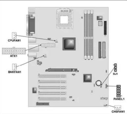
Mainboard Components

Table of Mainboard Components
| Label Component | |
| 1394A-J2 IEEE 1394A header | |
| AGP1 Accelerated Graphics Port | |
| ATX1 Standard 20-pin ATX power connector | |
| AUDIO1 Front audio connector | |
| BAT1 Three volt realtime clock battery | |
| BAKFAN1 Case fan connector 2 | |
| CHSFAN1 Case fan connector | |
| CDIN1 Primary CD-in connector | |
| CDIN2 | Secondary CD-in |
| CNR1 Communications Networking Riser slot | |
| CPU SOCKET Micro PGA | 478-pin socket for Pentium 4 CPUs |
| CHSFAN1 Chassis Fan connector | |
| CPUFAN1 Cooling fan for CPU | |
| DIMM1, DIMM2, DIMM3 | Three 184-pin DDR SDRAM |
| FDD1 Floppy disk drive connector | |
| FIDJP1 CPU ratio selector | |
| IDE 1 Primary IDE channel | |
| IDE 2 Secondary IDE channel | |
| IR1 | Infrared port |
| SMI1 | System Management Interrupt |
| J5/J6 | Serial ATA header |
| JP1 | Clear CMOS jumper |
| JP6 | Serial ATA jumper |
| LED1 ^1 | Memory module LED |
| PANEL1 | Connector for case front panel switches and LED indicators |
| PCI1 ~ PCI5 | Five 32-bit add-on card slots |
| SJ1 | Single color LED header |
| SPEAKER1 | Speaker connector |
| SPDIFO1 SPDIF out header | |
| USB3 Connector for front panel USB ports | |
This concludes Chapter 1. The next chapter explains how to install the main-board.
Chapter 2
Installing the Mainboard
Safety Precautions
Follow these safety precautions when installing the mainboard:
- Wear a grounding strap attached to a grounded device to avoid damage from static electricity.
- Discharge static electricity by touching the metal case of a safely grounded object before working on the mainboard.
- Leave components in the static-proof bags they came in.
- Hold all circuit boards by the edges. Do not bend circuit boards.
Quick Guide
This Quick Guide suggests the steps you can take to assemble your system with the mainboards.
The following table provides a reference for installing specific components:
Locating Mainboard Components Go to page 6
Installing the Mainboard in a Case Go to page 9
Setting Jumpers Go to page 9
Installing Case Components Go to page 12
Installing the CPU Go to page 15
Installing Memory Go to page 17
Installing a HDD and CD-ROM Drive Go to page 18
Installing an FDD Go to page 20
Installing Add-on Cards Go to page 21
Connecting Options Go to page 23
Connecting Peripheral (I/O) Devices Go to page 26
Installing the Mainboard in a Case
Refer to the following illustration and instructions for installing the mainboard in a case:
This illustration shows an example of a mainboard being installed in a tower-type case:
Note: Do not overtighten the screws as this can stress the main-board.
Most system cases have mounting brackets installed in the case, which correspond to the holes in the mainboard. Place the mainboard over the mounting brackets and secure the mainboard onto the mounting brackets with screws.
- Secure the mainboard with screws where appropriate.

Ensure that your case has an I/O template that supports the I/O ports and expansion slots on your mainboard.
Checking Jumper Settings
This section explains how to set jumpers for correct configuration of the mainboard.
Setting Jumpers
Use the mainboard jumpers to set system configuration options. Jumpers with more than one pin are numbered. When setting the jumpers, ensure that the jumper caps are placed on the correct pins.
The illustrations below show a 2-pin jumper. When the jumper cap is placed on both pins, the jumper is SHORT. If you remove the jumper cap, or place the jumper cap on just one pin, the jumper is OPEN.
This illustration shows a 3-pin jumper. Pins 1 and 2 are SHORT.

Short

Open

Checking Jumper Settings
The following illustration shows the location of the mainboard jumpers. Pin 1 is labeled.

Jumper Settings
| Jumper | Type | Description | Setting (default) | |
| JP1 | 3-pin | Clear CMOS | 1-2: Normal2-3: Clear CMOS | |
| JP6 | 3-pin | SATA HDD | 1-2: Enable2-3: Disable | |
| FID JP1 10-pin CPU ratio selector Refer to the table on the next page. | ||||
Jumper 1 – This jumper is use to clear all the current data stored in the CMOS memory. Refer to the following instructions:
- Turn the system off.
- Short pins 2 and 3 on jumper 1.
- Return the jumper to the normal setting.
- Turn the system on. The BIOS is returned to the default settings.
Jumper 6 – Use this jumper to disabled or enabled the Serial ATA func-
tion.
FIDJP1 – Sets the CPU ratio. Refer to the following table.
| 1-2 | 3-4 | 5-6 | 7-8 | 9-10 | Ratio |
| Short | — | — | — | — | By |
| Open | Open | Open | Open | Open | 10.5 |
| Open | Open | Open | Open | Short | 6.5 |
| Open | Open | Open | Short | Open | 8.5 |
| Open | Open | Open | Short | Short | 12.5 |
| Open | Open | Short | Open | Open | 9.5 |
| Open | Open | Short | Open | Short | 5.5 |
| Open | Open | Short | Short | Open | 7.5 |
| Open | Open | Short | Short | Short | 11.5 |
| Open | Short | Open | Open | Open | 10.0 |
| Open | Short | Open | Open | Short | 6.0 |
| Open | Short | Open | Short | Open | 8.0 |
| Open | Short | Open | Short | Short | 12.0 |
| Open | Short | Short | Open | Open | 9.0 |
| Open | Short | Short | Open | Short | 5.0 |
| Open | Short | Short | Short | Open | 7.0 |
| Open | Short | Short | Short | Short | 11.0 |
CPU
Connecting Case Components
After you have installed the mainboard into a case, you can begin connecting the mainboard components. Refer to the following:
- Connect the standard power supply connector to ATX1.
- Connect the CPU cooling fan cable to CPUFAN1.
- Connect the power cooling fan connector to BAKFAN1.
- Connect the chassis cooling fan connector to CHSFAN1.
- Connect the case LED cable to SJ1.
- Connect the case switches and indicator to PANEL1.
CPUFAN1/BAKFAN1/CHSFAN1: FAN Power Connectors
| Pin Signal Name Function | |||
| 1 | GND | System | Ground |
| 2 | +12V | Power | +12V |
| 3 | Sense | Sensor | |
ATX1: ATX 20-pin Power Connector
| Pin Signal Name Pin Signal Name | |||
| 1 | +3.3V | 11 | +3.3V |
| 2 | +3.3V | 12 | -12V |
| 3 | Ground | 13 | Ground |
| 4 | +5V | 14 | PS ON# |
| 5 | Ground | 15 | Ground |
| 6 | +5V | 16 | Ground |
| 7 | Ground | 17 | Ground |
| 8 | PWRGD | 18 | +5V |
| 9 | +5VSB | 19 | +5V |
| 10 | +12V | 20 | +5V |
SJ1: Single color LED header
| Pin Signal Name Function | ||
| 1 ACPI | LED MSG LED (-) green | |
| 2 ACPI | LED MSG LED (-) green | |
| 3 | SB5V Power | LED (-) |
ACPI LED function:
| SJ11 | S0 S1 S3 S4/S5 | |||
| Light | Blinking | Blinking | Dark | |
Front Panel Connector
The front panel connector (PANEL1) provides a standard set of switch and LED connectors commonly found on ATX or micro-ATX cases. Refer to the table below for information:
![Pin Signal Name Function 1 HD_LED_P Hard disk LED (positive) 2 FP PWR/SLP MSG LED [dual color or single color (+)] 3 HD_LED_N Hard disk active LED (negative) 4 FP PWR/SLP MSG LED [dual color or single color (-)] 5 RST_SW_N Reset Switch 6 PWR_SW_P Power Switch 7 RST_SW_P Reset Switch 8 PWR_SW_N Power Switch 9 RSVD Reserved 10 NC No pin](/content/2026/06/1209699/images/75efbd71fa20f3ec437b1ea0f6222558469c86afd827288bc9ac0a72b12d7933.jpg)
PANEL1
Hard Drive Activity LED
Connecting pins 1 and 3 to a front panel mounted LED provides visual indication that data is being read from or written to the hard drive. For the LED to function properly, an IDE drive should be connected to the onboard IDE interface. The LED will also show activity for devices connected to the SCSI (hard drive activity LED) connector.
Power / Sleep / Message Waiting LED
Connecting pins 2 and 4 to a single- or dual-color, front panel mounted LED provides power on/off, sleep, and message waiting indication.
Reset Switch
Supporting the reset function requires connecting pins 5 and 7 to a momentary-contact switch that is normally open. When the switch is closed, the board resets and runs POST.
Power Switch
Supporting the power on/off function requires connecting pins 6 and 8 to a momentary-contact switch that is normally open. The switch should maintain contact for at least 50 ms to signal the power supply to switch on or off. The time requirement is due to internal debounce circuitry. After receiving a power on/off signal, at least two seconds elapses before the power supply recognizes another on/off signal.
Installing Hardware
Installing the Processor
Caution: When installing a CPU heatsink and cooling fan make sure that you DO NOT scratch the mainboard or any of the surface-mount resistors with the clip of the cooling fan. If the clip of the cooling fan scrapes across the mainboard, you may cause serious damage to the mainboard or its components.
On most mainboards, there are small surface-mount resistors near the processor socket, which may be damaged if the cooling fan is carelessly installed.
Avoid using cooling fans with sharp edges on the fan casing and the clips. Also, install the cooling fan in a well-lit work area so that you can clearly see the mainboard and processor socket.
Before installing the Processor
This mainboard automatically determines the CPU clock frequency and system bus frequency for the processor. You may be able to change these settings by making changes to jumpers on the mainboard, or changing the settings in the system Setup Utility. We strongly recommend that you do not overclock processors or other components to run faster than their rated speed.
Warning: Overclocking components can adversely affect the reliability of the system and introduce errors into your system. Overclocking can permanently damage the mainboard by generating excess heat in components that are run beyond the rated limits.
This mainboard has a Socket 462 processor socket. When choosing a processor, consider the performance requirements of the system. Performance is based on the processor design, the clock speed and system bus frequency of the processor, and the quantity of internal cache memory and external cache memory.
CPU Installation Procedure
The following illustration shows CPU installation components:

Note: The pin-1 corner is marked with an arrow
Follow these instructions to install the CPU:
| 1. Pull the CPU socket locking lever away from the socket to unhook it and raise the locking lever to the upright position. | |
| 2. Match the corner on the CPU marked with an arrow with pin A-1 on the CPU socket (the corner with the pinhole noticeably missing). Insert the processor into the socket. Do not use force. | |
| 3. Swing the locking lever down and hook it under the latch on the edge of the socket. | |
| 4. Apply thermal grease to the top of the CPU. | |
| 5. Lower the CPU cooling fan/heatsink assembly onto the CPU | |
| 6. Secure the two retention clips on either side of the fan/heatsink unit onto the Socket 462 base. | 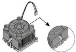 Fan/heatsink unit secured to socket Fan/heatsink unit secured to socket |
| 7. Connect the CPU Cooling Fan power cable connector to the CPUFAN connector. |  |
Notes:
• To achieve better airflow rates and heat dissipation, we suggest that you use a high quality fan with 4800 rpm at least.
- CPU fan and heatsink installation procedures may vary with the type of CPU fan/heatsink supplied. The form and size of fan/heatsink may also vary.
Installing Memory Modules
This mainboard accommodates three 184-pin 2.5V unbuffered Double Data Rate (DDR) SDRAM memory modules. The memory chips must be standard or registered SDRAM (Synchronous Dynamic Random Access Memory). The memory bus can run up to 166 MHz.
When you installed DDR333 memory modules, the memory bus can run up to 166 MHz. If you have DDR266, this can operate over a 133 MHz. For DDR200, it can only run up to 100 MHz.
Note: SDRAM provides 800 MBps or 1 GBps data transfer depending on whether the bus is 100MHz or 133MHz. Double Data Rate SDRAM (DDR SDRAM) doubles the rate to 1.6 GBps and 2.1 GBps. DDR SDRAM uses additional power and ground lines and requires 184-pin DIMM modules rather than the 168-pin DIMMs used by SDRAM.
The mainboard accommodates three memory modules. You must install at least one module in any of the three slots. Each module can be installed with 32 MB to 1 GB of memory; total memory capacity is 3 GB.

Do not remove any memory module from its antistatic packaging until you are ready to install it on the mainboard. Handle the modules only by their edges. Do not touch the components or metal parts. Always wear a grounding strap when you handle the modules.
Installation Procedure
Refer to the following to install the memory modules.
- This mainboard supports unbuffered DDR SDRAM only. Do not attempt to insert any other type of DDR SDRAM into the slots.

-
Push the latches on each side of the DIMM slot down.
-
Align the memory module with the slot. The DIMM slots are keyed with notches and the DIMMs are keyed with cutouts so that they can only be installed correctly.

-
Check that the cutouts on the DIMM module edge connector match the notches in the DIMM slot.
-
Install the DIMM module into the slot and press it firmly down until it seats correctly. The slot latches are levered upwards and latch on to the edges of the DIMM.
-
Install any remaining DIMM modules.

natural_image
Two identical diagrams showing a rectangular device with internal components and directional arrows, no text or symbols present.Installing a Hard Disk Drive/CD-ROM
This section describes how to install IDE devices such as a hard disk drive and a CD-ROM drive.
About IDE1 and IDE2 Devices
Your mainboard has a primary and secondary IDE channel interface (IDE1 and IDE2). An IDE ribbon cable supporting two IDE devices is bundled with the mainboard.
If you want to install more than two IDE devices, get a second IDE cable and you can add two more devices to the secondary IDE channel.
IDE devices have jumpers or switches that are used to set the IDE device as MASTER or SLAVE. Refer to the IDE device user's manual. When installing two IDE devices on one cable, ensure that one device is set to MASTER and the other device is set to SLAVE. The documentation of your IDE device explains how to do this.
About UltraDMA
This mainboard supports UltraDMA 66/100/133. UDMA is a technology that accelerates the performance of devices in the IDE channel. To maximize performance, install IDE devices that support UDMA and use 80-pin IDE cables that support UDMA 66/100/133.
Installing a Hard Disk Drive
-
Install the hard disk drive into the drive cage in your system case.
-
Plug the IDE cable into IDE1 (A):
Note: Ribbon cable connectors are usually keyed so that they can only be installed correctly on the device connector. If the connector is not keyed, make sure that you match the pin-1 side of the cable connector with the pin-1 side of the device connector. Each connector has the pin-1 side clearly marked. The pin-1 side of each ribbon cable is always marked with a colored stripe on the cable.

-
Plug an IDE cable connector into the hard disk drive IDE connector (B). It doesn't matter which connector on the cable you use.
-
Plug a power cable from the case power supply into the power connector on the hard disk drive (C).
When you first start up your system, the BIOS should automatically detect your hard disk drive. If it doesn't, enter the Setup Utility and use the IDE Hard Disk Auto Detect feature to configure the hard disk drive that you have installed.
Installing a CD-ROM/DVD Drive
-
Install the CD-ROM/DVD drive into the drive cage in your system case.
-
Plug the IDE cable into IDE1 (A). If you have already installed an HDD, use the other connector on the IDE cable.
Note: Ribbon cable connectors are usually keyed so that they can only be installed correctly on the device connector. If the connector is not keyed, make sure that you match the pin-1 side of the cable connector with the pin-1 side of the device connector. Each connector has the pin-1 side clearly marked. The pin-1 side of each ribbon cable is always marked with a colored stripe on the cable.

-
Plug an IDE cable connector into the CD-ROM/DVD drive IDE connector (B). It doesn't matter which connector on the cable you use.
-
Plug a power cable from the case power supply into the power connector on the CD-ROM/DVD drive (C).
-
Use the audio cable provided with the CD-ROM/DVD drive to connect to the mainboard CD-in connector CDIN1 or CDIN2 (D).
When you first start up your system, the BIOS should automatically detect your CD-ROM/DVD drive. If it doesn't, enter the Setup Utility and configure the CD-ROM/DVD drive that you have installed.
Installing a Floppy Diskette Drive
The mainboard has a floppy diskette drive (FDD) interface and ships with a diskette drive ribbon cable that supports one or two floppy diskette drives. You can install a 5.25-inch drive and a 3.5-inch drive with various capacities. The floppy diskette drive cable has one type of connector for a 5.25-inch drive and another type of connector for a 3.5-inch drive.
| 1. Install the FDD into the drive cage in your system case. | |
| 2. Plug the FDD cable into FLOPPY1 (A):Note: Ribbon cable connectors are usually keyed so that they can only be installed correctly on the device connector. If the connector is not keyed, make sure that you match the pin-1 side of the cable connector with the pin-1 side of the device connector. Each connector has the pin-1 side clearly marked. The pin-1 side of each ribbon cable is always marked with a colored stripe on the cable. |  |
| 3. Plug the correct connector on the FDD cable for the 5.25-inch or 3.5-inch drive into the FDD connector (B). | |
| 4. Plug a power cable from the case power supply into the power connector on the FDD (C). | |
When you first start up your system, go immediately to the Setup Utility to configure the floppy diskette drives that you have installed.
Installing Add-on Cards
This mainboard has five 32-bit PCI (Peripheral Components Interconnect) expansion slots, one AGP slot (supports 1.5V AGP Interface only), and one Communications and Networking Riser (CNR) slot.

PCI Slots PCI slots are used to install expansion cards that have the 32-bit PCI interface.
AGP Slot
The AGP slot is used to install graphics adapter that supports the 1.5V 8x AGP card which is also backward compatible with 4x AGP card.
Note: The above layout is for reference only. The AGP slot may be different from your mainboard. Please refer to actual shipment.
CNR Slot This slot is used to insert CNR cards with Modem and Audio functionality.
Note: Before installing an add-on card, check the documentation for the card carefully. If the card is not Plug and Play, you may have to manually configure the card before installation.
Follow these instructions to install an add-on card:
| 1. Remove a blanking plate from the system case corresponding to the slot you are going to use. | |
| 2. Install the edge connector of the add-on card into the expansion slot. Ensure that the edge connector is correctly seated in the slot. |  |
| 3. Secure the metal bracket of the card to the system case with a screw. | |
Note: For some add-on cards, for example graphics adapters and network adapters, you have to install drivers and software before you can begin using the add-on card.
Connecting Optional Devices
Refer to the following for information on connecting the mainboard's optional devices:

AUDIO1: Front Panel Audio header
This header allows the user to install auxiliary front-oriented microphone and line-out ports for easier access.
| Pin Signal Name Function | ||
| 1 AUD | MIC Front Panel Microphone input signal | |
| 2 AUD | GND Ground used by | Analog Audio Circuits |
| 3 | AUD_MIC_BIAS | Microphone Power |
| 4 AUD | VCC Filtered +5 V used by Analog Audio Circuits | |
| 5 AUD | FPOUT_R Right Channel | Audio signal to Front Panel |
| 6 AUD | RET_R Right Channel | Audio signal to Return from Front Panel |
| 7 HP_ON | Reserved for future | use to control Head-phone Amplifier |
| 8 | KEY | No Pin |
| 9 AUD | FPOUT_L Left Channel | Audio signal to Front Panel |
| 10 AUD | RET_L Left Channel | Audio signal to Front Panel |
USB3: Front panel USB connectors
The mainboard has four USB ports installed on the rear edge I/O port array. Additionally, some computer cases have USB ports at the front of the case. If you have this kind of case, use auxiliary USB connector USB3 to connect the front-mounted ports to the mainboard.
| Pin Signal Name Function | ||
| 1 VREG_FP_USBPWR0 Front Panel USB Power | ||
| 2 VREG_FP_USBPWR0 Front Panel USB Power | ||
| 3 USB_FP_P0- USB Port 0 Negative Signal | ||
| 4 USB_FP_P1- USB Port 1 Negative Signal | ||
| 5 USB_FP_P0+ USB Port 0 Positive Signal | ||
| 6 USB_FP_P1+ USB Port 1 Positive Signal | ||
| 7 | GND | Ground |
| 8 | GND | Ground |
| 9 | KEY | No pin |
| 10 Not assigned Not assigned | ||
Note: Please make sure that the USB cable has the same pin assignment as indicated above. A different pin assignment may cause damage or system hang-up.
IR1: Infrared port
Infrared ports allow the wireless exchange of information between your computer and similarly equipped devices such as printers, laptops, Personal Digital Assistants (PDAs), and other computers.
| Pin Signal Name Function | |||
| 1 Not assigned Not assigned | |||
| 2 | KEY | No | pin |
| 3 | +5V | IR | Power |
| 4 | GND | Ground | |
| 5 IRTX | IrDA serial output | ||
| 6 IRRX | IrDA serial input | ||
SPDIFO1: SPDIF out header
You can purchase an optional 24-bit digital audio extension bracket from a third-party vendor. You can use the audio RCA jacks to connect to digital audio devices. If your CD-ROM/DVD drive has digital audio output, you can connect it to the input pins of the SPDIF connector.
| Pin Signal Name Function | ||
| 1 SPDIF | SPDIF digital output | |
| 2 +5VA | 5V analog power | |
| 3 | NC | Not connected |
| 4 | GND | Ground |
1394A\_J2: IEEE 1394A header
Use this header to connect to any IEEE 1394A interface.
| Pin Signal Name Pin Signal Name | |||
| 1 | Cable-power | 5 | TPA- |
| 2 | GND | 6 | TPA+ |
| 3 | TPB- | 7 | Chassis |
| 4 | TPB+ | 8 | NC |
GND
J6/J5: Serial ATA header
This connector is use to support the new Serial ATA devices for the highest date transfer rates (1.5 Gbps burst), simpler disk drive cabling and easier PC assembly. It eliminates limitations of the current Parallel ATA interface. But maintains register compatibility and software compatibility with Parallel ATA.
SMI1: System Management Interrupt
This connector is for use with SMI hardware interrupt power management.
| Pin Signal Name Function | |||
| 1 | -EXTSMI | Sleep | button |
| 2 | GND | Ground | |
Connecting I/O Devices
The backplane of the mainboard has the following I/O ports:

PS/2 Mouse Use the upper PS/2 port to connect a PS/2 pointing device.
PS/2 Keyboard Use the lower PS/2 port to connect a PS/2 keyboard.
LPT1 Use LPT1 to connect printers or other parallel communications devices.
COM1/2 Use the COM ports to connect serial devices such as mice or fax/modems. COM1 is identified by the system as COM1/3. COM2 is identified by the system as COM2/4.
1394a Port (optional) Use the 1394a port to connect any Firewire device.
Audio Ports Use the three audio ports to connect audio devices. The first jack is for stereo line-in signal. The second jack is for stereo line-out signal. The third jack is for microphone.
LAN Port (optional) Connect an RJ-45 jack to the LAN port to connect your computer to the Network.
USB Ports Use the USB ports to connect USB devices.
External Connector Color Coding
Many connectors now use standard colors as shown in the table below.
| Connector | Color |
| Audio line-in Light blue | |
| Audio line-out Lime | |
| Digital monitor/flat panel White | |
| IEEE 1394 Grey | |
| Microphone | Pink |
| MIDI/game | Gold |
| Parallel | Burgundy |
| PS/2-compatible keyboard Purple | |
| PS/2-compatible mouse Green | |
| Serial | Teal |
| Speaker out/subwoofer Orange | |
| Right-to-left speaker Brown | |
| USB | Black |
| Video out Yellow | |
| SCSI, network, telephone, modem None |
or
Turquoise
This concludes Chapter 2. The next chapter covers the BIOS.
About the Setup Utility
The computer uses the latest AMI BIOS with support for Windows Plug and Play. The CMOS chip on the mainboard contains the ROM setup instructions for configuring the mainboard BIOS.
The BIOS (Basic Input and Output System) Setup Utility displays the system's configuration status and provides you with options to set system parameters. The parameters are stored in battery-backed-up CMOS RAM that saves this information when the power is turned off. When the system is turned back on, the system is configured with the values you stored in CMOS.
The BIOS Setup Utility enables you to configure:
• Hard drives, diskette drives, and peripherals
• Video display type and display options
- Password protection from unauthorized use
• Power management features
The settings made in the Setup Utility affect how the computer performs. Before using the Setup Utility, ensure that you understand the Setup Utility options.
This chapter provides explanations for Setup Utility options.
The Standard Configuration
A standard configuration has already been set in the Setup Utility. However, we recommend that you read this chapter in case you need to make any changes in the future.
This Setup Utility should be used:
- when changing the system configuration
- when a configuration error is detected and you are prompted to make changes to the Setup Utility
- when trying to resolve IRQ conflicts
- when making changes to the Power Management configuration
- when changing the password or making other changes to the Security Setup
Running the Setup Utility
Each time your computer starts, before the operating system loads, a message appears on the screen that prompts you to "Hit if you want to run SETUP". When you see this message, press the Delete key and the Main menu page of the Setup Utility appears on your monitor.

BIOS Navigation Keys
You can use the cursor arrow keys to highlight any of the options on the main menu page. Press Enter to select the highlighted option. To exit the setup utility, press the Escape key. To cycle through the Setup Utility's optional color schemes press down the F2/F3.
Some of the options on the main menu page lead to tables of items with installed values. In these pages, use the cursor arrow keys to highlight the items, and then use the PgUp and PgDn keys to cycle through the alternate values for each item. Other options on the main menu page lead to dialog boxes that require you to answer Yes or No by hitting the Y or N keys.
If you have already made changes to the setup utility, press F10 to save those changes and exit the utility. Press F5 to reset the changes to the original values. Press F6 to install the setup utility with a set of high-performance values.
Using BIOS
When you start the Setup Utility, the main menu appears. The main menu of the Setup Utility displays a list of the options that are available. A highlight indicates which option is currently selected. Use the cursor arrow keys to move the highlight to other options. When an option is highlighted, execute the option by pressing
Some options lead to pop-up dialog boxes that prompt you to verify that you wish to execute that option. Other options lead to dialog boxes that prompt you for information.
Some options (marked with a triangle ▶) lead to submenus that enable you to change the values for the option. Use the cursor arrow keys to scroll through the items in the submenu.
In this manual, default values are enclosed in parenthesis. Submenu items are denoted by a triangle ▶
Standard CMOS Setup
The Standard CMOS setup is used to modify basic system configuration data, such as date, time floppy and hard disk drive types, video type and keyboard.
| AMIEIOS SETUP - STANDARD CMOS SETUP (C)2001 American Megatrends, Inc. All Rights Reserved | |||
| Date (mm/dd/yyyy): Fr1 Sep 13,2002 Time (hh/mm/ss) : 11:08:31 Floppy Drive A: Not Installed Floppy Drive B: Not Installed Type Size CyIn Head WPcom Sec LBA 81k PIO 32Bit Pri Master: Not Installed Pri Slave: Not Installed Sec Master: Not Installed Sec Slave: Not Installed Boot Sector Virus Protection Disabled | |||
| Month: Jan - Dec Day: 01 - 31 Year: 1980 - 2099 | ESC:Exit ||:Sel PgUp/PgDn:Modify F1:Help F2/F3:Color | ||
Date & Time
Use these items to set the system date and time.
Floppy Drive A/Floppy Drive B
Use these items to set the size and capacity of the floppy diskette drive(s) installed in the system.
Pri Master/Pri Slave/Sec Master/Sec Slave
Use these items to configure devices connected to the Primary and Secondary IDE channels. To configure an IDE hard disk drive, choose Auto. If the Auto setting fails to find a hard disk drive, set it to User, and then fill in the hard disk characteristics (Size, Cyls, etc.) manually. If you have a CD-ROM
drive, select the setting CDROM. If you have an ATAPI device with removable media (e.g. a ZIP drive or an LS-120) select Floptical.
Advanced CMOS Setup
The Advanced CMOS setup is used to control advanced system information such as hardware access and boot settings.

Quick Boot (Enabled)
If you enable this item, the system starts up more quickly be elimination some of the power on test routines.
Pri/Sec Master ARMD Emulated as (Auto)
Pri/Sec Slave ARMD Emulated as (Auto)
These four options ensure that, if you have an ARMD attached as a master or slave device, it can properly detected by the system.
1^st Boot Device/ 2^nd Boot Device/ 3^rd Boot Device (Disabled)
Use these items to determine the device order the computer uses to look for an operating system to load at start-up time.
Try Other Boot Devices (Yes)
If you enable this item, the system will also search for other boot devices if it fails to find an operating system from the first two locations.
Initial Display Mode (BIOS)
This option specifies the initial display mode when the system boots.
Display Mode at Add-On ROM Init (Force BIOS)
This option allows OEM logo to show during boot-up.
Floppy Access Control (Read-Write)
This option specifies the read/write access that is set when booting from a floppy drive.
Hard Disk Access Control (Read-Write)
This option specifies the read/write access that is set when booting from a hard disk drive.
S.M.A.R.T for Hard Disks (Disabled)
Set this option to Enabled to permit the BIOS to use the SMART (System Management and Reporting Technologies) protocol for reporting server system information over a network. Enabling this feature allows you to back up your data when your hard disk is about to fail. If a password has been set for the supervisor, this item will not be visible for the user.
BootUp Num-Lock (On)
Set this option to Off to turn the Num Lock key off when the computer is booted you can use the arrow keys in both the numeric keypad and the keyboard.
PS/2 Mouse Support (Enabled)
Set this option to Enabled to enable the BIOS support for a PS/2-type mouse. The BIOS will allocate IRQ12 for the PS/2 mouse.
Primary Display (VGA/EGA)
This option configures the type of monitor attached to the computer.
Password Check (Setup)
This option enables password checking every time the system boots or when you run the BIOS Setup. If you choose Always, a user password prompt appears every time the computer is turned on. If you choose Setup, the password prompt appears if the BIOS is executed.
Boot To OS/2 (No)
Set this option to Enabled if running an OS/2 operating system and using more than 64 MB of system memory on the mainboard.
Internal Cache (Write Back)
This option sets the type of caching algorithm used by the L1 internal cache memory on the CPU.
External Cache (Write Back)
This option sets the type of caching algorithm used by the L1 external cache memory on the CPU.
System BIOS Cacheable (Disabled)
When set to Enabled, the contents of the F0000h system memory segment can be read from or written to cache memory. If parts of the BIOS ROM are frequently used, these parts are copied to cache memory for faster execution.
Advanced Chipset Setup
The Advanced Chipset Setup option is used to change the values of the chipset registers. These registers control most of the system options in the computer. You should leave the items on this page at their default values, if you change the values incorrectly, you may introduce fatal errors or recurring instability into your system.
| AMIBIOS SETUP - ADVANCED CHIPSET SETUP (C)2001 American Megatrends, Inc. All Rights Reserved | ||
| CPU Frequency | 133 MHz | |
| CPU/DRAM Clock Ratio | [1:1] | |
| DRAM Frequency | 133 MHz | |
| Auto Detect DIMM/PCI Clk | Enabled | |
| Clock Spread Spectrum Enable | Enabled | |
| Serial ATA Mode | RAID Mode | |
| On Board LAN | Enabled | |
| LAN Boot ROM Support | Disabled | |
| BIOS Write Protect | Disabled | |
| Fast Synchronizer | Enable | |
| DRAM Timing Configuration | Normal Mode | |
| Graphic Win Size | 128M | |
| IO APIC Support | Enable | |
| DDR CAS Latency | SPD | |
| ESC:Exit ↑↓:Sel PgUp/PgDn:Modify F1:Help F2/F3:Color | ||
Current Frequency (133 MHz)
This item displays the current frequency. This is a display-only item. You cannot make changes to this field.
CPU/DRAM Clock Ratio ([1:1])
Enables you to set the CPU and DRAM clock.
DRAM Frequency (133 MHz)
This item displays the memory (DRAM) frequency. This is a display-only item. You cannot make changes to this field.
Auto Detect DIMM/PCI Clk (Enabled)
When this item is enabled, BIOS will disable the clock signal of free DIMM and PCI slots.
Clock Spread Spectrum Enable (Enabled)
The Clock Spread Spectrum significantly reduces the EMI (Electro Magnetic Interference) generated by the system.
Serial ATA Mode Select (RAID Mode)
Use this item to select the mode of the Serial ATA.
On Board LAN (Enabled)
Enables and disables the onboard LAN.
LAN Boot ROM Support (Disabled)
Use this item to enable and disable the booting from the onboard LAN with a remote boot ROM installed.
BIOS Write Protect (Disabled)
This option protects the BIOS from accidental corruption by unauthorized users or computer viruses. When enabled, the BIOS' data cannot be changed when attempting to update the BIOS with a Flash utility. To successfully update the BIOS, you'll need to disable this BIOS Write Protect function.
Fast Synchronizer (Enable)
This option enables you to adjust the timing between CPU and DRAM to enhance performance.
DRAM Timing Configuration (Normal Mode)
The DRAM timing is controlled by the DRAM Timing Registers. The Timings programmed into this register are dependent on the system design. Slower rates may be required in certain system designs to support loose layouts or slower memory.
Graphic Win Size (128M)
This setting controls just how much system RAM can be allocated to AGP for video purposes.
IO APIC Support (Enable)
This item allows you to enable or disable the APIC (Advanced Programmable Interrupt Controller) mode. APIC provides symmetric multi-processing (SMP) for systems, allowing support for up to 60 processors.
DDR CAS to Latency (SPD)
This item determines the operation of the DDR memory CAS (column address strobe). We recommend that you leave this item at the default value.
Power Management Setup
The Power Management Setup Menu option is used to change the values of the chipset registers for system power management.
| AMIBIOS SETUP - POWER MANAGEMENT SETUP(C)2001 American Megatrends, Inc. All Rights Reserved | ||
| Power Switch Type | On/Off | Available Options:► On/OffSuspend |
| ACPI Aware O/S | Yes | |
| ACPI Standby State | S1 | |
| Power Management | Enabled | |
| Suspend Time Out | Disabled | |
| Hard Disk Time Out | Disabled | |
| RTC Alarm Resume From Soft Off | Disabled | |
| RTC Alarm Date | Every Day | |
| RTC Alarm Hour | 12 | |
| RTC Alarm Minute | 30 | |
| RTC Alarm Second | 00 | |
| Resume on PME | Enabled | |
| Resume On Mac PME | Enabled | |
| Wake on Ring/Lan | Disabled | |
| Keyboard PowerOn Function | Disabled | |
| USB Device Lead To Power On | Disabled | |
| Resume on PS2 Mouse | Disabled | |
| PS2 MOUSE Wake Select Mode | Bottom | ESC:Exit ↑↓:SelPgUp/PgDn:ModifyF1:Help F2/F3:Color |
| Restore on AC/Power Loss | Power Off | |
Power Switch Type (On/Off)
This option specifies how the power button is used. In the Suspend mode, the hard disk motor is spindled down, the monitor is shut down, and the processor clock is stopped.
ACPI Aware O/S (Yes)
Set this option to Yes to enable Advanced Configuration and Power Interface (ACPI) BIOS for an ACPI-aware operating system.
ACPI Standby State (S1)
This item allows you to select the standby type under ACPI operating system.
Power Management (Enabled)
Set this option to Enabled to enable the chipset power management and APM (Advanced Power Management) features.
Suspend Time Out (Disabled)
This option defines the length of time that the system while in Standby mode, it must be inactive before it enters Suspend mode.
This option specifies the length of period of hard disk drive inactivity. When this time period expires, the computer enters the power-conserving state specified in the Hard Disk Power Down Mode option.
RTC Alarm Resume From Soft Off (Disabled)
This option enable or disable the RTC alarm to wake up the system from Soft Off.
Resume On RTC Alarm / Date / Hour / Minute / Second
The system can be turned off with a software command. If you enable this item, the system can automatically resume at a fixed time based on the system's RTC (realtime clock). Use the items below this one to set the date and time of the wake-up alarm. You must use an ATX power supply in order to use this feature.
Resume on PME (Disabled)
This option allows you to enable or disable the Resume on PME function.
Wake on Ring/LAN (Disabled)
The system can be turned off with a software command. If you enable this item, the system can automatically resume if there is an incoming call on the Modem. You must use an ATX power supply in order to use this feature.
Keyboard PowerOn Function (Disabled)
If you enable this item, you can turn the system on and off by pressing hot keys on the keyboard. You must enable the Keyboard Power On jumper and use an ATX power supply in order to use this feature.
USB Device Lead To Power On (Disabled)
If you enable this item, the system can automatically resume if there is traffic on the USB device.
Resume on PS2 Mouse (Disabled)
This option allows you to enable or disable the Resume on PS2 mouse function.
PS2 MOUSE Wake Select Mode (Bottom)
This option allows you to set the mouse action to turn on the system.
Restore on AC/Power Loss (Power Off)
This sets the power state after a shutdown due to an unexpected interrupt of AC power.
PCI / Plug and Play Setup
This section describes configuring the PCI bus system. PCI (Peripheral Component Interconnect) is a system, which allows I/O devices to operate at speeds nearing CPU's when they communicate with own special components.
All the options describes in this section are important and technical and it is strongly recommended that only experienced users should make any changes to the default settings.
| AMIBIOS SETUP - PCI / PLUG AND PLAY SETUP (C)2001 American Megatrends, Inc. All Rights Reserved | ||
| Allocate IRQ to PCI VGA PCI IDE BusMaster OffBoard PCI IDE Cord OffBoard PCI IDE Primary IRQ OffBoard PCI IDE Secondary IRQ DMA Channel 0 DMA Channel 1 DMA Channel 3 DMA Channel 5 DMA Channel 6 DMA Channel 7 IRQ3 IRQ4 IRQ5 IRQ7 IRQ9 IRQ10 IRQ11 IRQ14 IRQ15 | Yes Enabled Auto Disabled Disabled PnP PnP PnP PnP PnP PCI/PnP PCI/PnP PCI/PnP PCI/PnP PCI/PnP PCI/PnP PCI/PnP PCI/PnP | Available Options: ► PCI/PnP ISA/EISA |
Plug and Play Aware O/S (Yes)
Enable this item if you are using an O/S that supports Plug and Play such as Windows 95/98/ME.
PCI IDE BusMaster (Enabled)
Set this option to Enabled to specify that the IDE controller on the PCI bus has bus mastering capability.
OffBoard PCI IDE Card (Auto)
This option specifies if an offboard PCI IDE controller adapter card is used in the computer. You must also specify the PCI expansion slot on the mainboard where the offboard PCI IDE controller card is installed. If an offboard PCI IDE controller is used, the onboard IDE controller is automatically disabled.
OffBoard PCI IDE Primary IRQ (Disabled)
This option specifies the PCI interrupt used by the primary IDE channel on the offboard PCI IDE controller.
OffBoard PCI IDE Secondary IRQ (Disabled)
This option specifies the PCI interrupt used by the secondary IDE channel on the offboard PCI IDE controller.
DMA Channel 0/1/3/5/6/7 (PnP)
This option allows you to specify the bus type used by each DMA channel.
IRQ (PCI/ PnP)
This option specifies the bus that the specified IRQ line is used on. They allow you to reserve IRQs for legacy ISA adapter cards and determine if the BIOS should remove an IRQ from the pool of available IRQs passed to devices that are configurable by the system BIOS. The available IRQ pool is determined by reading the ESCD NVRAM. If more IRQs must be removed from the pool, the end user can use these options to reserve the IRQ by assigning an ISA/EISA setting to it. Onboard I/O is configured by the BIOS. All IRQs used by onboard I/O are configured as PCI/PnP. IRQ12 only appears if the PS/2 Mouse Support option in Advanced Setup is set to Disabled. IRQ14 and 15 will not be available if the onboard PCI IDE is enabled.
Peripheral Setup
The Peripheral Setup menu describes I/O resources assignment for all of the on-board peripheral devices.
| AMIBIOS SETUP - PERIPHERAL SETUP (C)2001 American Megatrends, Inc. All Rights Reserved | ||
| --SiS963 Device Control-- | Available Options: ▶ | |
| Audio Device | Enabled | |
| Modem Device | Enabled | |
| USB 2.0 Supports | Enabled | |
| USB Ports Supports | Enable | |
| USB Function | Enabled | |
| USB KB/Mouse/FDD Legacy Support | Disabled | |
| Onboard 1394 Device | Enable | |
| --SiS950 Device Control-- | ||
| OnBoard FDC | Auto | |
| OnBoard Serial PortA | Auto | |
| OnBoard Serial PortB | Auto | |
| Serial Port2 Mode | Normal | |
| OnBoard Parallel Port | Auto | |
| Parallel Port Mode | ECP | |
| Parallel Port IRQ | Auto | |
| Parallel Port DMA | Auto | |
| --SiS963 PCI IDE Control-- | ESC:Exit ↑↓:Sel PgUp/PgDn:Modify F1:Help F2/F3:Color | |
| Onboard PCI IDE | Both | |
Audio Device (Enabled)
This item enables or disables the onboard AC'97 audio chip.
Modem Device (Enabled)
This item enables or disables the onboard AC'97 modem chip.
USB 2.0 Supports (Enabled)
This item enables or disables the onboard USB 2.0.
USB Ports Supports (Enable)
Enable this item if you plan to use the USB ports on this mainboard.
USB Function (Enabled)
Enable this item if you plan to use the USB ports on this mainboard.
USB KB/Mouse/FDD Legacy Support (Disabled)
Set this item to enable to support for older keyboard and mouse devices if the
USB option is set to enable.
Onboard 1394 Device (Enable)
Enable this item if you plan to use the onboard 1394 device.
OnBoard FDC (Auto)
Set this option to Enabled to enable the floppy drive controller on the main-board.
OnBoard Serial PortA (Auto)
This option specifies the base I/O port address of serial port A.
OnBoard Serial PortB (Auto)
This option specifies the base I/O port address of serial port B.
Serial Port2 Mode (Normal)
Use this item to allocate the resources of the second serial port. Under Normal, the resources are allocated to the onboard serial port. Under ASKIR or IrDA, the resources are allocated to the onboard IR port.
OnBoard Parallel Port (Auto)
This option specifies the base I/O port address for the parallel port on the mainboard.
Parallel Port Mode (ECP)
This option specifies the parallel port mode.
Parallel Port IRQ (Auto)
Use this item to assign either IRQ 5 or 7 to the parallel port.
Parallel Port DMA (Auto)
Use this item to assign a DMA channel to the parallel port. The options are 0, 1 and 3.
Onboard PCI IDE (Both)
Use this item to enable or disable either or both of the onboard Primary and Secondary IDE channels.
Hardware Monitor Page
This section sets some of the parameters for the hardware monitoring function of this mainboard.
| AMIBIOS SETUP - HARDWARE MONITOR SETUP (C)2001 American Megatrends, Inc. All Rights Reserved | ||
| --System Hardware Monitor | E-- | Available Options: ► =-- |
| CPU Vcore | 1.632 V | |
| Vcc2.5V | 2.512 V | |
| +3.3V | 3.168 V | |
| +5V | 4.784 V | |
| +12V | 12.032 V | |
| SB-3.3V | 3.424 V | |
| SB-5V | 4.892 V | |
| BAK Fan1 Speed | 0 RPM | |
| SYSTEM Fan Speed | 0 RPM | |
| CPU FAN Speed | 4115 RPM | |
| SYSTEM Temperature | 44°C/111°F | |
| CPU Temperature | 80°C/176°F | |
| ESC:Exit ↑↓:Sel PgUp/PgDn:Modify F1:Help F2/F3:Color | ||
CPU / System Temperature
These items display CPU and system temperature measurement.
FANs & Voltage Measurements
These items indicate cooling fan speeds in RPM and the various system voltage measurements.
Change Supervisor/User Password
When this function is selected, the following message appears at the center of the screen to assist you in creating a password.
ENTER PASSWORD
Type the password, up to eight characters, and press
To disable password, just press
PASSWORD DISABLED
If you have selected "System" in "Security Option" of "BIOS Features Setup" menu, you will be prompted for the password every time the system reboots or any time you try to enter BIOS Setup.
If you have selected "Setup" at "Security Option" from "BIOS Features Setup" menu, you will be prompted for the password only when you enter BIOS Setup.
Supervisor Password has higher priority than User Password. You can use Supervisor Password when booting the system or entering BIOS Setup to modify all settings. Also you can use User Password when booting the system or entering BIOS Setup but can not modify any setting if Supervisor Password is enabled.
Auto Configuration with Optimal Settings
If you select this item and press Enter a dialog box appears. If you press Y, and then Enter, the Setup Utility loads a set of fail-safe default values. These default values are not very demanding and they should allow your system to function with most kinds of hardware and memory chips.
Note: It is highly recommended that users enter this option to load optimal values for accessing the best performance.
Auto Configuration with Fail Safe Settings
This option opens a dialog box that lets you install fail-safe defaults for all appropriate items in the Setup Utility:
Press
Save Settings and Exit
Highlight this item and press
Exit Without Saving
Highlight this item and press
Note: If you have made settings that you do not want to save, use the "Exit Without Saving" item and press
This concludes Chapter 3. Refer to the next chapter for information on the software supplied with the mainboard.
About the Software CD-ROM
The support software CD-ROM that is included in the mainboard package contains all the drivers and utility programs needed to properly run the bundled products. Below you can find a brief description of each software program, and the location for your mainboard version. More information on some programs is available in a README file, located in the same directory as the software.
Note: Never try to install software from a folder that is not specified for use with your mainboard.
Before installing any software, always inspect the folder for files named RE-ADME.TXT, INSTALL.TXT, or something similar. These files may contain important information that is not included in this manual.
Auto-installing under Windows 98/ME/2000/XP
The Auto-install CD-ROM makes it easy for you to install the drivers and software for your mainboard.
Note: If the Auto-install CD-ROM does not work on your system, you can still install drivers through the file manager for your OS (for example, Windows Explorer). Refer to Utility Folder Installation Notes later in this chapter.
The support software CD-ROM disc loads automatically under Windows 98/ME/2000/XP. When you insert the CD-ROM disc in the CD-ROM drive, the autorun feature will automatically bring up the install screen. The screen has three buttons on it, Setup, Browse CD and Exit.

Note: If the opening screen doesn't appear, double-click the file "setup.exe" in the root directory.
Setup Tab
| Setup | Click the Setup button to run the software installation program.Select from the menu which software you want to install. |
| Browse CD | The Browse CD button is the standard Windows command that allows you to open Windows Explorer and show the contents of the support CD.Before installing the software from Windows Explorer, look for a file named README.TXT, INSTALL.TXT or something similar.This file may contain important information to help you install the software correctly.Some software is installed in separate folders for different operating systems, such as DOS, WIN NT, or WIN98/95. Always go to the correct folder for the kind of OS you are using.To install the software, execute a file named SETUP.EXE or INSTALL.EXE by double-clicking the file and then following the instructions on the screen. |
| Exit | The Exit button closes the Auto Setup window. |
Application Tab
Lists the software utilities that are available on the CD.
Read Me Tab
Displays the path for all software and drivers available on the CD.
Running Setup
Follow these instructions to install device drivers and software for the main-board:
- Click Setup. The installation program begins:

Note: The following screens are examples only. The screens and driver lists will be different according to the mainboard you are installing.
The mainboard identification is located in the upper left-hand corner.
- Click Next. The following screen appears:

-
Check the box next to the items you want to install. The default options are recommended.
-
Click Next run the Installation Wizard. An item installation screen appears:

- Follow the instructions on the screen to install the items.
Drivers and software are automatically installed in sequence. Follow the on-screen instructions, confirm commands and allow the computer to restart a few times to complete the installation.
Manual Installation
Insert the CD in the CD-ROM drive and locate the PATH.DOC file in the root directory. This file contains the information needed to locate the drivers for your mainboard.
Look for the chipset and mainboard model; then browse to the directory and path to begin installing the drivers. Most drivers have a setup program (SETUP.EXE) that automatically detects your operating system before installation. Other drivers have the setup program located in the operating system subfolder.
If the driver you want to install does not have a setup program, browse to the operating system subfolder and locate the readme text file (README.TXT or README.DOC) for information on installing the driver or software for your operating system.
Utility Software Reference
All the utility software available from this page is Windows compliant. They are provided only for the convenience of the customer. The following software is furnished under license and may only be used or copied in accordance with the terms of the license.
Note: These software(s) are subject to change at anytime without prior notice. Please refer to the support CD for available software.
AWARD Flash Memory Utility
This utility lets you erase the system BIOS stored on a Flash Memory chip on the mainboard, and lets you copy an updated version of the BIOS to the chip. Proceed with caution when using this program. If you erase the current BIOS and fail to write a new BIOS, or write a new BIOS that is incorrect, your system will malfunction. Refer to Chapter 3, Using BIOS for more information.
WinFlash Utility
The Award WinFlash utility is a Windows version of the DOS Award BIOS flash writer utility. The utility enables you to flash the system BIOS stored on a Flash Memory chip on the mainboard while in a Windows environment. This utility is currently available for WINXP\ME\2000\98SE. To install the WinFlash utility, run WINFLASH.EXE from the following directory:
\UTILITY\WINFLASH 1.51
PC-CILLIN 2002
The PC-CILLIN 2002 software program provides anti-virus protection for your system. This program is available for Windows 2000/ME/98SE/XP and Windows NT. Be sure to check the readme.txt and install the appropriate anti-virus software for your operating system.
We strongly recommend users to install this free anti-virus software to help protect your system against viruses.
MediaRing Talk – Telephony Software
To install the MediaRing Talk voice modem software for the built-in modem, go to the directory \UTILITY\MEDIARING TALK, then run MRTALK-SETUP72.EXE to install the application software.
Super Voice – Fax/Modem Software
To install the Super Voice voice, fax, data communication application for use with the built-in fax/modem, go the directory \UTILITY\SUPER_VOICE, then run PICSHELL.EXE to install the application software.
CD Ghost
The CD Ghost software enables you to create a virtual cabinet of CD-ROM drives on your system to help you categorize and organize your CD collection. A user-friendly interface assists you in quickly creating images of both CDs and DVDs onto your system. To install the software, run SETUP.EXE from the following directory:
\UTILITY\CDGHOST\ENG\CDGHOST
Recovery Genius
The Recovery Genius software program is an innovative windows application system that protects your Hard Disk Drive from virus intrusion, accidental deletions and from system corruption. To install the Recovery Genius software program run SETUP.EXE from the following directory:
\UTILITY\RECOVERY GENIUS\ENG\RECOVERYGENIUS
Language Genius
The Language Genius is a software -based product that helps you to learn new languages. To install the Language Genius software program run SETUP.EXE from the following directory:
\UTILITY\LANGUAGE GENIUS\ENG\LANGUAGEGENIUS
PageABC
The PageABC application software enables you to create your very own home page. To install the PageABC, go to the directory \UTILITYPageABC, and then run SETUP.EXE to install the application software.
This concludes Chapter 4.


- Disclaimer
- Trademark Recognition
- Federal Communications Commission (FCC)
- Declaration of Conformity
- Canadian Department of Communications
- Features and Packing List Translations
- Liste de contrôle
- CHAPTER 1 1
- CHAPTER 2 8
- CHAPTER 3 28
- Using BIOS 28
- CHAPTER 4 43
- Using the Mainboard Software 43
- Introduction
- Checklist
- Standard Items
- Choosing a Computer Case
- Chapter 2
- Installing the Mainboard
- Safety Precautions
- Quick Guide
- Installing the Mainboard in a Case
- Checking Jumper Settings
- Setting Jumpers
- Connecting Case Components
- Front Panel Connector
- Hard Drive Activity LED
- Power / Sleep / Message Waiting LED
- Reset Switch
- Power Switch
- Installing Hardware
- Installing the Processor
- Before installing the Processor
- CPU Installation Procedure
- Notes:
- Installing Memory Modules
- Installation Procedure
- Installing a Hard Disk Drive/CD-ROM
- About IDE1 and IDE2 Devices
- About UltraDMA
- Installing a Hard Disk Drive
- Installing a CD-ROM/DVD Drive
- Installing a Floppy Diskette Drive
- Installing Add-on Cards
- Connecting Optional Devices
- AUDIO1: Front Panel Audio header
- USB3: Front panel USB connectors
- IR1: Infrared port
- SPDIFO1: SPDIF out header
- 1394A\_J2: IEEE 1394A header
- J6/J5: Serial ATA header
- SMI1: System Management Interrupt
- Connecting I/O Devices
- External Connector Color Coding
- About the Setup Utility
- The Standard Configuration
- Running the Setup Utility
- BIOS Navigation Keys
- Using BIOS
- Standard CMOS Setup
- Date & Time
- Floppy Drive A/Floppy Drive B
- Pri Master/Pri Slave/Sec Master/Sec Slave
- Advanced CMOS Setup
- Quick Boot (Enabled)
- Pri/Sec Master ARMD Emulated as (Auto)
- Pri/Sec Slave ARMD Emulated as (Auto)
- 1st Boot Device/ 2nd Boot Device/ 3rd Boot Device (Disabled)
- Try Other Boot Devices (Yes)
- Initial Display Mode (BIOS)
- Display Mode at Add-On ROM Init (Force BIOS)
- Floppy Access Control (Read-Write)
- Hard Disk Access Control (Read-Write)
- S.M.A.R.T for Hard Disks (Disabled)
- BootUp Num-Lock (On)
- PS/2 Mouse Support (Enabled)
- Primary Display (VGA/EGA)
- Password Check (Setup)
- Boot To OS/2 (No)
- Internal Cache (Write Back)
- External Cache (Write Back)
- System BIOS Cacheable (Disabled)
- Advanced Chipset Setup
- Current Frequency (133 MHz)
- CPU/DRAM Clock Ratio ([1:1])
- DRAM Frequency (133 MHz)
- Auto Detect DIMM/PCI Clk (Enabled)
- Clock Spread Spectrum Enable (Enabled)
- Serial ATA Mode Select (RAID Mode)
- On Board LAN (Enabled)
- LAN Boot ROM Support (Disabled)
- BIOS Write Protect (Disabled)
- Fast Synchronizer (Enable)
- DRAM Timing Configuration (Normal Mode)
- Graphic Win Size (128M)
- IO APIC Support (Enable)
- DDR CAS to Latency (SPD)
- Power Management Setup
- Power Switch Type (On/Off)
- ACPI Aware O/S (Yes)
- ACPI Standby State (S1)
- Power Management (Enabled)
- Suspend Time Out (Disabled)
- RTC Alarm Resume From Soft Off (Disabled)
- Resume On RTC Alarm / Date / Hour / Minute / Second
- Resume on PME (Disabled)
- Wake on Ring/LAN (Disabled)
- Keyboard PowerOn Function (Disabled)
- USB Device Lead To Power On (Disabled)
- Resume on PS2 Mouse (Disabled)
- PS2 MOUSE Wake Select Mode (Bottom)
- Restore on AC/Power Loss (Power Off)
- PCI / Plug and Play Setup
- Plug and Play Aware O/S (Yes)
- PCI IDE BusMaster (Enabled)
- OffBoard PCI IDE Card (Auto)
- OffBoard PCI IDE Primary IRQ (Disabled)
- OffBoard PCI IDE Secondary IRQ (Disabled)
- DMA Channel 0/1/3/5/6/7 (PnP)
- IRQ (PCI/ PnP)
- Peripheral Setup
- Audio Device (Enabled)
- Modem Device (Enabled)
- USB 2.0 Supports (Enabled)
- USB Ports Supports (Enable)
- USB Function (Enabled)
- USB KB/Mouse/FDD Legacy Support (Disabled)
- Onboard 1394 Device (Enable)
- OnBoard FDC (Auto)
- OnBoard Serial PortA (Auto)
- OnBoard Serial PortB (Auto)
- Serial Port2 Mode (Normal)
- OnBoard Parallel Port (Auto)
- Parallel Port Mode (ECP)
- Parallel Port IRQ (Auto)
- Parallel Port DMA (Auto)
- Onboard PCI IDE (Both)
- Hardware Monitor Page
- FANs & Voltage Measurements
- Change Supervisor/User Password
- ENTER PASSWORD
- PASSWORD DISABLED
- Auto Configuration with Optimal Settings
- Auto Configuration with Fail Safe Settings
- Save Settings and Exit
- Exit Without Saving
- About the Software CD-ROM
- Auto-installing under Windows 98/ME/2000/XP
- Application Tab
- Read Me Tab
- Running Setup
- Manual Installation
- Utility Software Reference
- AWARD Flash Memory Utility
- WinFlash Utility
- PC-CILLIN 2002
- MediaRing Talk – Telephony Software
- Super Voice – Fax/Modem Software
- CD Ghost
- Recovery Genius
- Language Genius
- PageABC
Brand : ECS
Model : L7S7A
Category : Tablet