
HDC-I/E-240 - Tablet ECS - Free user manual and instructions
Find the device manual for free HDC-I/E-240 ECS in PDF.

| Product Type | Motherboard (Mini-ITX form factor) |
| Dimensions | 170 mm x 170 mm |
| Chipset | AMD Hudson M1 FCH |
| Processor | Onboard AMD FT1 (E-350, dual-core 1.6 GHz) |
| Memory Support | 2 x 240-pin DDR3 DIMM slots, up to 8 GB, DDR3 1066/800 |
| Expansion Slots | 1 x PCI Express x16 (x4 mode), 1 x Mini PCI Express x1 |
| Storage Interfaces | 4 x SATA 6.0 Gb/s |
| Audio | VT1708B 5.1 Channel High Definition Audio |
| LAN | AR8151 Gigabit Ethernet (or AR8152 10/100) |
| Rear I/O Ports | 1 x SPDIFO, 1 x Bluetooth, 1 x DVI, 1 x VGA, 6 x USB 2.0, 2 x USB 3.0, 1 x LAN, 1 x eSATA, 1 x HDMI, audio jacks (mic, line-in, line-out) |
| Internal Connectors | 24-pin ATX power, 4 x SATA, 2 x USB 2.0 headers (support 4 additional ports), Front panel header, Front audio header, CPU/SYS fan connectors, Speaker header, Case open header, LVDS header (optional) |
| BIOS | AMI BIOS with 16Mb SPI Flash ROM, supports Plug and Play, ACPI, DMI, S1/STR(S3)/STD(S4), hardware monitor, overclocking, dual display |
| Power Supply | ATX power supply (24-pin connector) |
| Operating Temperature | 0°C to 50°C (recommended) |
| Safety Precautions | Wear grounding strap, discharge static electricity, handle boards by edges, avoid over-tightening screws |
| Maintenance | Keep in well-ventilated area, clean CPU cooler fan regularly, avoid dust and moisture, use earth ground power cord |
| Spare Parts and Repairability | Contact ECS support for replacement parts and repair services |
| General Information | Mini-ITX motherboard for high-end business or personal desktop, supports Windows XP/Vista/7 |
Frequently Asked Questions - HDC-I/E-240 ECS
User questions about HDC-I/E-240 ECS
0 question about this device. Answer the ones you know or ask your own.
Ask a new question about this device
Download the instructions for your Tablet in PDF format for free! Find your manual HDC-I/E-240 - ECS and take your electronic device back in hand. On this page are published all the documents necessary for the use of your device. HDC-I/E-240 by ECS.
USER MANUAL HDC-I/E-240 ECS
This publication, including all photographs, illustrations and software, is protected under international copyright laws, with all rights reserved. Neither this manual, nor any of the material contained herein, may be reproduced without written consent of the author.
Version 1.0
Disclaimer
The information in this document is subject to change without notice. The manufacturer makes no representations or warranties with respect to the contents hereof and specifically disclaims any implied warranties of merchantability or fitness for any particular purpose. The manufacturer reserves the right to revise this publication and to make changes from time to time in the content hereof without obligation of the manufacturer to notify any person of such revision or changes.
Trademark Recognition
Microsoft, MS-DOS and Windows are registered trademarks of Microsoft Corp.
MMX, Pentium, Pentium-II, Pentium-III, Celeron are registered trademarks of Intel Corporation.
Other product names used in this manual are the properties of their respective owners and are acknowledged.
Federal Communications Commission (FCC)
This equipment has been tested and found to comply with the limits for a Class B digital device, pursuant to Part 15 of the FCC Rules. These limits are designed to provide reasonable protection against harmful interference in a residential installation. This equipment generates, uses, and can radiate radio frequency energy and, if not installed and used in accordance with the instructions, may cause harmful interference to radio communications. However, there is no guarantee that interference will not occur in a particular installation. If this equipment does cause harmful interference to radio or television reception, which can be determined by turning the equipment off and on, the user is encouraged to try to correct the interference by one or more of the following measures:
- Reorient or relocate the receiving antenna
- Increase the separation between the equipment and the receiver
- Connect the equipment onto an outlet on a circuit different from that to which the receiver is connected
- Consult the dealer or an experienced radio/TV technician for help
Shielded interconnect cables and a shielded AC power cable must be employed with this equipment to ensure compliance with the pertinent RF emission limits governing this device. Changes or modifications not expressly approved by the system's manufacturer could void the user's authority to operate the equipment.
Preface

This device complies with part 15 of the FCC rules. Operation is subject to the following conditions:
• This device may not cause harmful interference, and
- This device must accept any interference received, including interference that may cause undesired operation

This class B digital apparatus meets all requirements of the Canadian Interference-causing Equipment Regulations.
The manual consists of the following:
Chapter 1
Introducing the Motherboard
| Describes features of the motherboard. |
Go to

page 1
Chapter 2
Installing the Motherboard
| Describes installation of motherboard components. |
Go to

page 7
Chapter 3
Using BIOS
| Provides information on using the BIOS Setup Utility. |
Go to

page 21
Chapter 4
Using the Motherboard Software
| Describes the motherboard software. |
Go to

page 41
Chapter 5
Trouble Shooting
| Provides basic trouble shooting tips |
Go to

page 45
TABLE OF CONTENTSABLE OF CONTENTS
Preface i
Chapter 11
Introducing the Motherboard 1
Introduction....1
Feature....2
Specifications....4
Motherboard Components....5
Chapter 2 7
Installing the Motherboard 7
Safety Precautions....7
Choosing a Computer Case....7
Installing the Motherboard in a Case....7
Checking Jumper Settings....8
Setting Jumpers....8
Checking Jumper Settings....9
Jumper Settings....9
Installing Hardware....10
Installing Memory Modules....10
Expansion Slots....11
Connecting Optional Devices....13
Installing a SATA Hard Drive....16
Connecting I/O Devices....17
Connecting Case Components....18
Front Panel Header....20
Chapter 3 21
Using BIOS 21
About the Setup Utility....21
The Standard Configuration....21
Entering the Setup Utility....21
Resetting the Default CMOS Values....22
Using BIOS....22
BIOS Navigation Keys....23
Main Menu....23
Advanced Menu....24
Chipset Menu....33
Frequency/Voltage Control Menu....35
Boot Menu....36
Security Menu....37
Save & Exit Menu....38
Updating the BIOS....40
※※□▼※□ √ √⊗ √⊗
Using the Motherboard Software 41
About the Software DVD-ROM/CD-ROM....41
Auto-installing under Windows XP/Vista/7....41
Running Setup....42
Manual Installation....44
Utility Software Reference....44
✿✿✿☐¶※☐ X √X √X
Trouble Shooting 45
Start up problems during assembly....45
Start up problems after prolong use....46
Maintenance and care tips....46
Basic Troubleshooting Flowchart....47
Introduction
Thank you for choosing the HDC-I motherboard. This is a high performance, enhanced function motherboard with onboard FT1 CPU for high-end business or personal desktop markets.
This motherboard is based on AMD Hudson M1 FCH Chipset for best desktop platform solution. Hudson M1 FCH is a single-chip, highly integrated, high performance. This motherboard supports up to 8GB of system memory with single channel DDR3 1066/800 MHz. High resolution graphics via one PCI Express X16 slot, intended for Graphics Interface. One Mini PCI Express X1 slot is also supported. It implements an EHCI compliant interface that provides ten USB 2.0 ports (six USB 2.0 ports at the rear panel and two USB 2.0 headers supporting additional four USB 2.0 ports). It also implements extra USB 3.0 chip which provides two USB 3.0 ports at the rear I/O with blue connectors. This motherboard integrates a Serial ATA host controller, supporting four SATA ports with maximum transfer rate up to 6.0 Gb/s each.
The motherboard is equipped with advanced full set of I/O ports in the rear panel, including one DVI port, one eSATA port, one VGA port, six USB 2.0 ports, two USB 3.0 ports, one Bluetooth, one HDMI port, one LAN port, one SPDIFO port and audio jacks for microphone, line-in and line-out.
Feature
Processor
This motherboard uses onboard AMD FT1 CPU that carries the following features:
- The onboard AMD FT1 processor combines the central processing unit (CPU) with the graphics processing unit (CPU) in a single-chip Accelerated Processing Unit (APU) package.
- The APU connects to the Fusion Controller Hub (FCH) through the Unified Media Interface (UMI) to provide connections to the different system devices.
Chipset
The AMD Hudson M1 FCH chipset is a single-chip with proven reliability and performance.
• Supports one PCI Express X16 slot (running at x4 mode)
• Supports one Mini PCI Express X1 slot
- Integrated SATA 6.0 Gb/s Host Controller
• Ten USB 2.0 ports supported
• Supports Unified Media interface(UMI), SMBus controller, and High Definition Audio
• Supports Serial Peripheral Interface (SPI)
- Enhanced DMA Controller, power management, hardware monitoring, interrupt controller, and clock function.
Memory
• Supports DDR3 1066/800 SDRAM with Dual-channel architecture
- Accommodates two unbuffered DIMMs
- 2 x 240-pin DDR3 SDRAM sockets support up to 8 GB
Onboard LAN(Optional)
• Supports PCI Express TM 1.1
• Integrated 10/100/1000 transceiver
• Integrated Switching Regulator
- Wake-on-LAN and remote wake-up support
• Supports PCI Express TM 1.1
• Integrated 10/100 transceiver
• Integrated Linear Regulator
- Wake-on-LAN and remote wake-up support
Audio
This motherboard may support either of the following Audio chipsets:
• 5.1 Channel High Definition Audio Codec
• ADCs support 44.1k/48k/96k/192kHz sample rate
- Exceeds Microsoft Windows Logo Program (WLP) Requirements
• Power support: Digital: 3.3 V; Analog: 5.0V
[Non-Text]
Expansion Options
The motherboard comes with the following expansion options:
• One PCI Express X16 slot (running at x4 mode) for Graphics Interface
• One Mini PCI Express X1 slot (with optional wireless card)
- Four 7-pin SATA connectors
Integrated I/O
The motherboard has a full set of I/O ports and connectors:
- One SPDIFO port
- One Bluetooth
- One DVI port
- One VGA port
• SIX USB 2.0 ports and two USB 3.0 ports - One LAN port
- One eSATA port
• One HDMI port
• Audio jacks for microphone, line-in and line-out
BIOS Firmware
This motherboard uses AMI BIOS that enables users to configure many system features including the following:
• Power management
- Wake-up alarms
- CPU parameters
• CPU and memory timing
The firmware can also be used to set parameters for different processor clock speeds.

-
Some hardware specifications and software items are subject to change without prior notice.
-
Due to chipset limitation, we recommend that motherboard be operated in the ambiance between 0 and 50°C.
Specifications
| CPU | • Onboard AMD FT1 Processor |
| Chipset | • AMD Hudson M1 chipset |
| Memory | • Dual-channel DDR3 memory architecture• 2 x 240-pin DDR3 DIMM sockets support up to 8 GB• Supports DDR3 1066/800 DDR3 SDRAM |
| Expansion Slots | • 1 x PCI Express X16 slot (running at x4 mode)• 1 x Mini PCI Express X1 slot (with optional wireless card) |
| Storage | • Supported by AMD Hudson M1 chipset• 4 x Serial ATA 6.0 Gb/s devices |
| Audio | • VT1708B |
| LAN | • AR8151 Gigalan (Co-lay 10/100 AR8152) |
| Rear Panel I/O | • One SPDIFO port• One Bluetooth• One DVI port• One VGA port• SIX USB 2.0 ports and two USB 3.0 ports• One LAN port• One eSATA port• One HDMI port• Audio jacks for microphone, line-in and line-out |
| Internal I/OConnectors & Headers | • 1 x 24-pin ATX Power Supply connector• 4 x Serial ATA 6.0 Gb/s connectors• 2 x USB 2.0 headers support additional 4 USB 2.0 ports• 1 x Clear CMOS header• 1 x Front panel header• 1 x Front panel audio header• CPU FAN/SYS FAN connectors• 1 x Speaker header• 1 x CASE Open header• 1 x LVDS header (Optional) |
| System BIOS | • AMI BIOS with 16Mb SPI Flash ROM• Supports Plug and Play, ACPI & DMI, S1/STR(S3)/STD(S4), Hardware monitor, Over-Clocking, Dual Dispaly• Audio, LAN, can be disabled in BIOS• F11 hot key for boot up devices option |
Form Factor • Mini-ITX Size, 170mm x 170mm
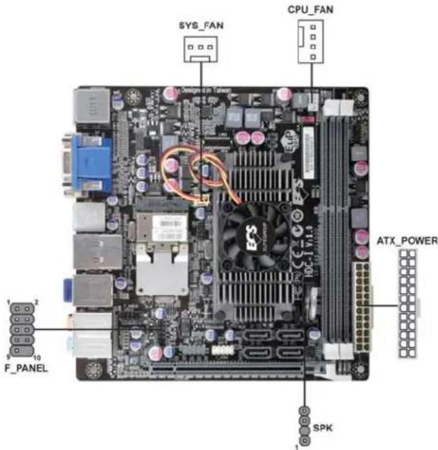
Motherboard Components
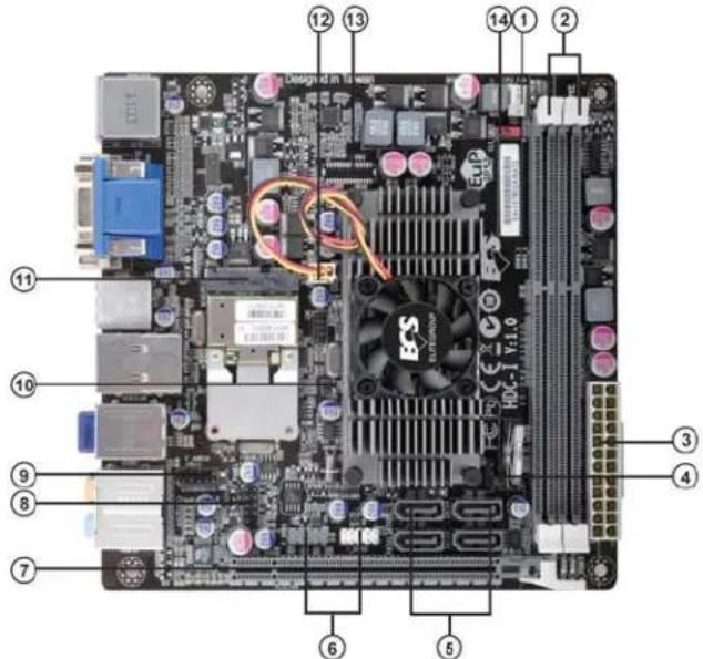
Table of Motherboard Components
| LABEL COMPONENTS | |
| 1. CPU_FAN CPU cooling fan connector | |
| 2. DDR3_1~2 240-pin DDR3 SDRAM slots | |
| 3. ATX_POWER Standard 24-pin ATX power connector | |
| 4. SPK External speaker header | |
| 5. SATA1~4 Serial ATA 6.0 Gb/s connectors | |
| 6. F_USB1~2 Front panel USB 2.0 header (F_USB1 supports EZ charger) | |
| 7. PCIE16X PCI Express x16 slot (running at x4 mode) | |
| 8. F_PANEL Front panel switch/LED header | |
| 9. F_AUDIO Front panel audio header | |
| 10. CASE CASE open header | |
| 11. MINIPCIE Mini PCI Express x1 slot (with optional wireless card) | |
| 12. SYS_FAN System cooling fan connector | |
| 13. LVDS LVDS header (Optional) | |
| 14. CLR_CMOS | Clear CMOS jumper |
This concludes Chapter 1. The next chapter explains how to install the motherboard.
*
★★○□
Chapter 2 Installing the Motherboard
Safety Precautions
- Follow these safety precautions when installing the motherboard
- Wear a grounding strap attached to a grounded device to avoid damage from static electricity
- Discharge static electricity by touching the metal case of a safely grounded object before working on the motherboard
- Leave components in the static-proof bags they came in
- Hold all circuit boards by the edges. Do not bend circuit boards
Choosing a Computer Case
There are many types of computer cases on the market. The motherboard complies with the specifications for the Mini ITX system case. First, some features on the motherboard are implemented by cabling connectors on the motherboard to indicators and switches on the system case. Make sure that your case supports all the features required. Secondly, this motherboard supports four enhanced SATA drives. Make sure that your case has sufficient power and space for all drives that you intend to install.
Most cases have a choice of I/O templates in the rear panel. Make sure that the I/O template in the case matches the I/O ports installed on the rear edge of the motherboard.
This motherboard carries a Mini ITX form factor of 170 x 170 mm. Choose a case that accommodates this form factor.
Installing the Motherboard in a Case
Refer to the following illustration and instructions for installing the motherboard in a case.
Most system cases have mounting brackets installed in the case, which correspond the holes in the motherboard. Place the motherboard over the mounting brackets and secure the motherboard onto the mounting brackets with screws.
Ensure that your case has an I/O template that supports the I/O ports and expansion slots on your motherboard.

natural_image
Top-down view of a computer motherboard with CPU socket, heatsink, and ventilation slots (no readable text or symbols)
Do not over-tighten the screws as this can stress the motherboard.
Checking Jumper Settings
This section explains how to set jumpers for correct configuration of the motherboard.
Setting Jumpers
Use the motherboard jumpers to set system configuration options. Jumpers with more than one pin are numbered. When setting the jumpers, ensure that the jumper caps are placed on the correct pins.
The illustrations show a 2-pin jumper. When the jumper cap is placed on both pins, the jumper is SHORT. If you remove the jumper cap, or place the jumper cap on just one pin, the jumper is OPEN.
This illustration shows a 3-pin jumper. Pins 1 and 2 are SHORT.

SHORT

OPEN

Installing the Motherboard
Checking Jumper Settings
The following illustration shows the location of the motherboard jumpers. Pin 1 is labeled.

Jumper Settings
| Jumper | Type | Description Setting (default) | ||
| CLR_CMOS | 3-pin | Clear CMOS | 1-2: NORMAL2-3: CLEARBefore clearing the CMOS, make sure to turn off the system. | 1 [IMAGE]CLR_CMOS |

To avoid the system instability after clearing CMOS, we recommend users to enter the main BIOS setting page to "Load Default Settings" and then "Save and Exit Setup".
Installing Hardware
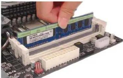
Installing Memory Modules
This motherboard accommodates two memory modules. It can support two 240-pin DDR3 1066/800. The total memory capacity is 8 GB.
DDR3 SDRAM memory module table
| Memory module Memory Bus | |
| DDR3 800 | 400 MHz |
| DDR3 1066 | 533 MHz |
You must install at least one module in any of the two slots. The total memory capacity is up to 8 GB.

Do not remove any memory module from its antistatic packaging until you are ready to install it on the motherboard. Handle the modules only by their edges. Do not touch the components or metal parts. Always wear a grounding strap when you handle the modules.
Installation Procedure
Refer to the following to install the memory modules.
1 This motherboard supports unbuffered DDR3 SDRAM.
2 Push the latches on each side of the DIMM slot down.
3 Align the memory module with the slot. The DIMM slots are keyed with notches and the DIMMs are keyed with cutouts so that they can only be installed correctly.
4 Check that the cutouts on the DIMM module edge connector match the notches in the DIMM slot.
5 Install the DIMM module into the slot and press it firmly down until it seats correctly. The slot latches are levered upwards and latch on to the edges of the DIMM.
6 Install any remaining DIMM modules.
* For reference only
Installing the Motherboard
Expansion Slots
Installing Add-on Cards
The slot on this motherboard is designed to hold expansion card and connect it to the system bus. Expansion slot is a mean of adding or enhancing the motherboard's features and capabilities. With these efficient facilities, you can increase the motherboard's capabilities by adding hardware that performs tasks that are not part of the basic system.
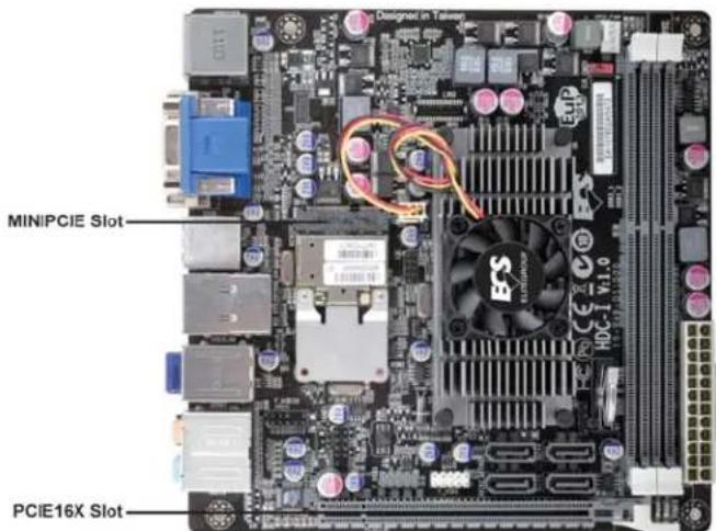
PCIE16X Slot The PCI Express x16 slot with x4 bandwidth is fully compliant to the PCI Express Base Specification revision 2.0.
MINIPCIE Slot The Mini PCI Express x1 slot is for extending usage, such as wireless card or TV card.

Before installing an add-on card, check the documentation for the card carefully. If the card is not Plug and Play, you may have to manually configure the card before installation.
Follow these instructions to install an add-on card:
1 Remove a blanking plate from the system case corresponding to the slot you are going to use.
2 Install the edge connector of the add-on card into the expansion slot. Ensure that the edge connector is correctly seated in the slot.
3 Secure the metal bracket of the card to the system case with a screw.

natural_image
Close-up of a computer motherboard with a CPU fan and heatsink (no visible text or symbols)* For reference only

For some add-on cards, for example graphics adapters and network adapters, you have to install drivers and software before you can begin using the add-on card.
Follow these instructions to install a wireless card:
1 Remove a blanking plate from the system case, and insert the wireless card into the MINIPCIE slot rightwards, then tighten the two screws (Please refer to Picture 1).
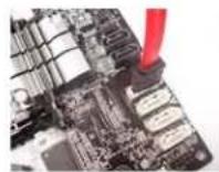
2 Press the metal connector of the cable into the connector on the wireless card. Ensure that the metal connector is correctly seated (Please refer to Picture 2).
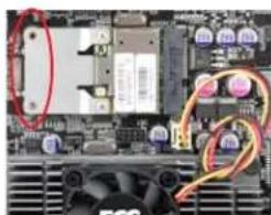
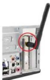
3 Make the other end of the cable (with a gold screw) through the upper hole of the bracket, and tighten the antenna on to the gold screw after installing a metal gasket on the screw (Please refer to Picture 3).
natural_image
Close-up of a computer motherboard with visible CPU socket and fan (no readable text or symbols)Picture 1

natural_image
Interior view of a computer motherboard showing drive bays and cable connections (no visible text or labels)Picture 2
natural_image
Close-up of a computer interface showing a black cable with a red circle highlighting a component (no visible text or symbols)Picture 3
Installing the Motherboard
Connecting Optional Devices
Refer to the following for information on connecting the motherboard's optional devices:

SATA1\~4: Serial ATA III connectors
These connectors are used to support the Serial ATA devices for the data transfer rates (6.0 Gb/s), simpler disk drive cabling and easier PC assembly. It eliminates limitations of the current Parallel ATA interface. But maintains register compatibility and software compatibility with Parallel ATA.
| n Signal Name Pin Signal Name | |||
| 1 Ground 2 TX+ | |||
| 3 TX- 4 Ground | |||
| 5 RX- 6 RX+ | |||
| 7 Ground - - | |||
F\_AUDIO: Front Panel Audio header for Azalia
This header allows the user to install auxiliary front-oriented microphone and line-out ports for easier access.
| Pin Signal Name Pin Signal Name | |||
| 1 PORT 1L 2 AUD_GND | |||
| 3 PORT 1R 4 PRESENCE# | |||
| 5 PORT 2R 6 SENSE_SEND | |||
| 7 AUD_GND 8 KEY | |||
| 9 | PORT 2L | 10 | SENSE_SEND |
Installing the Motherboard
F\_USB1\~2: Front Panel USB 2.0 headers (F\_USB1 supports EZ charger)
The motherboard has two USB 2.0 ports installed on the rear edge I/O port array. Additionally, some computer cases have USB 2.0 ports at the front of the case. If you have this kind of case, use auxiliary USB 2.0 connectors to connect the front-mounted ports to the motherboard.
Unlike F_USB2 in this motherboard, F_USB1 supports EZ charger technology, provides about 1A current than general USB port in off mode for USB devices. It is useful and excellent, especially for the iPhone, iPad and iPod touch devices that need a large amount of current for faster recharging within less time.
| Pin | Signal Name | Function |
| 1 | USBPWR Front Panel | USB Power |
| 2 | USBPWR Front Panel | USB Power |
| 3 | USB_FP_P0- USB Port 0 | Negative Signal |
| 4 | USB_FP_P1-USB Port 1 | Negative Signal |
| 5 | USB_FP_P0+ USB Port 0 | Positive Signal |
| 6 | USB_FP_P1+USB Port 1 | Positive Signal |
| 7 | GND Ground | |
| 8 | GND Ground | |
| 9 | Key No pin | |
| 10 | USB_FP_OC0 | GND |

Please make sure that the USB cable has the same pin assignment as indicated above. A different pin assignment may cause damage or system hang-up.
CASE: Chassis Intrusion Header
This detects if the chassis cover has been removed. This function needs a chassis equipped with intrusion detection switch and needs to be enabled in BIOS.
| Pin 1-2 Function | |
| Short Chassis cover is removed | |
| Open Chassis cover is closed |
LVDS: LVDS connector (Optional)
| Pin | Signal Name | Pin | Signal Name |
| 1 VDD 2 VDD | |||
| 3 GND 4 USB_GND | |||
| 5 V_LED 6 V_LED | |||
| 7 GND 8 GND | |||
| 9 PWM_LED 10 EN_LED | |||
| 11 USB_VCC 12 USB_D- | |||
| 13 USB_D+ 14 USB_GND | |||
| 15 V_EDID 16 GND | |||
| 17 RXIN0-18 RXIN0+ | |||
| 19 | GND | 20 | RXIN1- |
| 21 | RXIN1+ | 22 | GND |
| 23 | RXIN2- | 24 | RXIN2+ |
| 25 | GND | 26 | RXCLK+ |
| 27 | RXCLK- | 28 | GND |
| 29 | DATA-EDID | 30 | CLK-EDID |
Installing a SATA Hard Drive
This section describes how to install SATA connectors.
About SATA Connectors
Your motherboard features four SATA connectors supporting a total of four drives. SATA refers to Serial ATA (Advanced Technology Attachment) is the standard interface for the IDE hard drives which are currently used in most PCs. These connectors are well designed and will only fit in one orientation. Locate the SATA connectors on the motherboard and follow the illustration below to install the SATA hard drives.
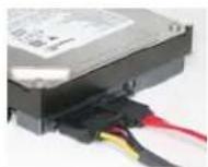
Installing Serial ATA Hard Drives
To install the Serial ATA (SATA) hard drives, use the SATA cable that supports the Serial ATA protocol. This SATA cable comes with an SATA power cable. You can connect either end of the SATA cable to the SATA hard drive or the connector on the motherboard.

SATA cable (optional)

SATA power cable (optional)
Refer to the illustration below for proper installation:
1 Attach either cable end to the connector on the motherboard.
2 Attach the other cable end to the SATA hard drive.
3 Attach the SATA power cable to the SATA hard drive and connect the other end to the power supply.

This motherboard does not support the "Hot-Plug" function.
Connecting I/O Devices
The backplane of the motherboard has the following I/O ports:
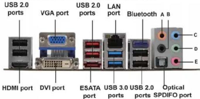
HDMI Port Connect the HDMI port to the HDMI devices.
DVI Port Use the DVI port to connect the monitor.
VGA Port Connect your monitor to the VGA port.
LAN Port Connect RJ-45 jacks to LAN port to connect your computer to the Network.
USB 2.0 Ports Use the USB 2.0 ports to connect USB 2.0 devices.
USB 3.0 Ports Use the USB 3.0 ports to connect USB 3.0 devices.
ESATA Port Use this port to connect to external SATA boxes or Serial ATA port multipliers.

Before connecting the eSATA cables, make sure to turn off the power of the external enclosure.
Bluetooth Used to connect to Bluetooth devices.
Optical SPDIF
Output
Audio Ports
This jack connects to external optical digital audio output devices.
This motherboard may adopt 8-channel audio ports that correspond to the A,B, C, and D port respectively. Users please refer to the following note for specific port function definition.
| A: Center & Bass out | C: Line in |
| B: Back Surround | D: Front Out |
| Optional SPDIFO Port | E: Mic in |
The above port definition can be changed to audio input or audio output by changing the driver utility setting.
Connecting Case Components
After you have installed the motherboard into a case, you can begin connecting the motherboard components. Refer to the following:
1 Connect the CPU cooling fan cable to CPU_FAN.
2 Connect the standard power supply connector to ATX POWER.
3 Connect the case switches and indicator LEDs to the F_PANEL.
4 Connect the system cooling fan connector to SYS_FAN.
5 Connect the case speaker cable to SPK.

Connecting 24-pin power cable
The ATX_POWER 24-pin connector allows you to connect to ATX v2.x power supply.
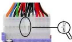
With ATX v2.x power supply, users please note that when installing 24-pin power cable, the latches of power cable and the ATX_POWER match perfectly.
24-pin power cable
CPU_FAN: CPU Cooling FAN Power Connector
| Pin Signal Name Function | ||
| 1 | GND System Ground | |
| 2 | +12V Power +12V | |
| 3 | Sense Sensor | |
| 4 | PWM | PWM |

Users please note that the fan connector supports the CPU cooling fan of 1.1A \~ 2.2A (26.4W max) at +12V.
ATX_POWER: ATX 24-pin Power Connector
| Pin | Signal Name | Pin | Signal Name |
| 1 | +3.3V | 13 | +3.3V |
| 2 | +3.3V | 14 | -12V |
| 3 | Ground | 15 | Ground |
| 4 | +5V | 16 | PS_ON |
| 5 | Ground | 17 | Ground |
| 6 | +5V | 18 | Ground |
| 7 | Ground | 19 | Ground |
| 8 | PWRGD | 20 | -5V |
| 9 | +5VSB | 21 | +5V |
| 10 | +12V | 22 | +5V |
| 11 | +12V | 23 | +5V |
| 12 | +3.3V | 24 | Ground |
SYS_FAN: System Cooling FAN Power Connector
| Pin Signal Name Function | ||
| 1 GNDSystemGround | ||
| 2 +12V Power +12V | ||
| 3 | Sense | Sensor |
SPK: Internal speaker
| Pin | Signal Name |
| 1 | VCC |
| 2 | Key |
| 3 | GND |
| 4 | Signal |
Front Panel Header
The front panel header (F_PANEL) provides a standard set of switch and LED headers commonly found on ATX or micro-ATX cases. Refer to the table below for information:
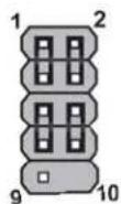
F_PANEL
| Pin Signal Function Pin Signal Function | ||
| 1 HD_LED_P Hard disk LED (+) 2 FP PWR/SLP*MSG LED (+) | ||
| 3 HD_LED_N Hard disk LED (-) | 4 FP PWR/SLP *MSG LED (-) | |
| 5 RST_SW_N Reset Switch (-) | 6 PWR_SW_P Power Switch (+) | |
| 7 RST_SW_P Reset Switch (+) | 8 PWR_SW_N Power Switch (-) | |
| 9 RSVD Reserved | 10 Key No pin | |
* MSG LED (dual color or single color)
Hard Drive Activity LED
Connecting pins 1 and 3 to a front panel mounted LED provides visual indication that data is being read from or written to the hard drive. For the LED to function properly, an IDE drive should be connected to the onboard IDE interface. The LED will also show activity for devices connected to the SCSI (hard drive activity LED) connector.
Power/Sleep/Message waiting LED
Connecting pins 2 and 4 to a single or dual-color, front panel mounted LED provides power on/off, sleep, and message waiting indication.
Reset Switch
Supporting the reset function requires connecting pins 5 and 7 to a momentary-contact switch that is normally open. When the switch is closed, the board resets and runs POST.
Power Switch
Supporting the power on/off function requires connecting pins 6 and 8 to a momentary-contact switch that is normally open. The switch should maintain contact for at least 50 ms to signal the power supply to switch on or off. The time requirement is due to internal de-bounce circuitry. After receiving a power on/off signal, at least two seconds elapses before the power supply recognizes another on/off signal.
This concludes Chapter 2. The next chapter covers the BIOS.
Chapter 3
Using BIOS
About the Setup Utility
The computer uses the latest “American Megatrends Inc.” BIOS with support for Windows Plug and Play. The CMOS chip on the motherboard contains the ROM setup instructions for configuring the motherboard BIOS.
The BIOS (Basic Input and Output System) Setup Utility displays the system's configuration status and provides you with options to set system parameters. The parameters are stored in battery-backed-up CMOS RAM that saves this information when the power is turned off. When the system is turned back on, the system is configured with the values you stored in CMOS.
The BIOS Setup Utility enables you to configure:
- Hard drives, diskette drives and peripherals
• Video display type and display options - Password protection from unauthorized use
• Power Management features
The settings made in the Setup Utility affect how the computer performs. Before using the Setup Utility, ensure that you understand the Setup Utility options.
This chapter provides explanations for Setup Utility options.
The Standard Configuration
A standard configuration has already been set in the Setup Utility. However, we recommend that you read this chapter in case you need to make any changes in the future.
This Setup Utility should be used:
- when changing the system configuration
- when a configuration error is detected and you are prompted to make changes to the Setup Utility
- when trying to resolve IRQ conflicts
- when making changes to the Power Management configuration
- when changing the password or making other changes to the Security Setup
Entering the Setup Utility
When you power on the system, BIOS enters the Power-On Self Test (POST) routines. POST is a series of built-in diagnostics performed by the BIOS. After the POST routines are completed, the following message appears:
Press DEL to enter SETUP
Press the delete key to access BIOS Setup Utility.
| Main Advanced Chipset Frequency/Voltage Control Boot Security Save & Exit | ||
| BIOS InformationSystem Language [English]System Date [Sat 12/18/2010]System Time [23:51:29] | Choose the system default language→ ←:Select Screen↓ :Select ItemEnter : Select+/- :Change Opt.F1:General HelpF2:Previous ValuesF3:Optimized DefaultsF4:Save & ExitESC:Exit | |
| Version 2.10.1208, Copyright (C) 2010, American Megatrends, Inc. | ||
Resetting the Default CMOS Values
When powering on for the first time, the POST screen may show a "CMOS Settings Wrong" message. This standard message will appear following a clear CMOS data at factory by the manufacturer. You simply need to Load Default Settings to reset the default CMOS values.
Note: Changes to system hardware such as different CPU, memories, etc. may also trigger this message.

Using BIOS
When you start the Setup Utility, the main menu appears. The main menu of the Setup Utility displays a list of the options that are available. A highlight indicates which option is currently selected. Use the cursor arrow keys to move the highlight to other options. When an option is highlighted, execute the option by pressing
Some options lead to pop-up dialog boxes that prompt you to verify that you wish to execute that option. Other options lead to dialog boxes that prompt you for information.
Some options (marked with a triangle ▶) lead to submenus that enable you to change the values for the option. Use the cursor arrow keys to scroll through the items in the submenu.
In this manual, default values are enclosed in parenthesis. Submenu items are denoted by a triangle ▶.

The default BIOS setting for this motherboard apply for most conditions with optimum performance. We do not suggest users change the default values in the BIOS setup and take no responsibility to any damage caused by changing the BIOS settings.
BIOS Navigation Keys
The BIOS navigation keys are listed below:
| KEY FUNCTION | |
| ESC | Exits the current menu |
| 1|--- | Scrolls through the items on a menu |
| +/- Modifies the selected field's values | |
| Enter | Select |
| F1 General Help | |
| F2 Previous Value | |
| F3 Optimized Defaults | |
| F4 Save & Exit | |

For the purpose of better product maintenance, the manufacture reserves the right to change the BIOS items presented in this manual. The BIOS setup screens shown in this chapter are for reference only and may differ from the actual BIOS. Please visit the manufacture's website for updated manual.
Main Menu
When you enter the BIOS Setup program, the main menu appears, giving you an overview of the basic system information. Select an item and press
| Main | Advanced Chipset Frequency/Voltage Control Boot Security Save & Exit | |
| BIOS Information | Set the Date. Use Tab to switch between Data elements. | |
| System Language [English] | ||
| System Date [Sat 12/18/2010] | → ←:Select Screen↑↓ :Select ItemEnter : Select+/- :Change Opt.F1:General HelpF2:Previous ValuesF3:Optimized DefaultsF4:Save & ExitESC:Exit | |
| System Time [23:51:29] | ||
| Version 2.10.1208. Copyright (C) 2010, American Megatrends, Inc. | ||
Date & Time
The Date and Time items show the current date and time on the computer. If you are running a Windows OS, these items are automatically updated whenever you make changes to the Windows Date and Time Properties utility.
Advanced Menu
The Advanced menu items allow you to change the settings for the CPU and other system.
| Aptio Setup Utility - Copyright (C) 2010 American Megatrends, Inc. | |
| Main Advanced Chipset Frequency/Voltage Control Boot Security Save & Exit | |
| Legacy OpROM SupportLaunch PXE OpROM [Disabled] | Enable or Disable Boot Optionfor Legacy Network Devices. |
| ▶ECS eJIFFY Function▶LAN Configuration | |
| ▶PC Health Status▶Power Management Setup▶ACPI Settings▶CPU Configuration▶SATA Configuration▶USB Configuration | → ←:Select Screen1↓ :Select ItemEnter : Select+/- : Change Opt.F1:General HelpF2:Previous ValuesF3:Optimized DefaultsF4:Save & ExitESC:Exit |
| Version 2.10.1208. Copyright (C) 2010, American Megatrends, Inc. | |
Launch PXE OpROM
The item enables or disables launch PXE Option ROM.
Launch Storage OpROM (Disabled)
The item enables or disables launch Storage Option ROM.
ECS eJIFFY Function
Scroll to this item and press
| Aptio Setup Utility - Copyright (C) 2010 American Megatrends, Inc. | |
| Main Advanced Chipset Frequency/Voltage Control Boot Security Save & Exit | |
| ECS eJIFFY FunctionECS eJIFFY Function [Disabled] | Make sure that the eJIFFY has been installed to hard disk. |
| → ←:Select Screen↑↓:Select ItemEnter: Select+/- : Change Opt.F1:General HelpF2:Previous ValuesF3:Optimized DefaultsF4:Save & ExitESC:Exit | |
| Version 2.10.1208, Copyright (C) 2010, American Megatrends, Inc. | |
ECS eJIFFY Function (Disabled)
This item allows you to enable or disable ECS eJIFFY Function.
Press
LAN Configuration
The item in the menu shows the LAN-related information that the BIOS automatically detects.
| Main Advanced Chipset Frequency/Voltage Control Boot Security Save & Exit | |
| LAN ConfigurationOnboard LAN Controller (Enabled) | Enable or Disable Onboard LAN |
| ←←:Select Screen11 :Select ItemEnter : Select+/- : Change Opt.F1:General HelpF2:Previous ValuesF3:Optimized DefaultsF4:Save & ExitESC:Exit | |
Onboard LAN Controller (Enabled)
Use this item to enable or disable the Onboard LAN.
Press
PC Health Status
On motherboards support hardware monitoring, this item lets you monitor the paemeters for critical voltages, temperatures and fan speeds.
| Aptio Setup Utility - Copyright (C) 2010 American Megatrends, Inc. | |
| Main Advanced Chipset Frequency/Voltage Control Boot Security Save & Exit | |
| Smart Fan Function CPU Tct1 : +61 System temperature : +35°C CPU FAN : 4249 RPM SYS FAN : N/A DIMM Voltage : +1.531 V | → ←:Select Screen ↓:Select Item Enter: Select +/-: Change Opt. F1:General Help F2:Previous Values F3:Optimized Defaults F4:Save & Exit ESC:Exit |
| Version 2.10.1208. Copyright (C) 2010, American Megatrends, Inc. | |
▶Smart Fan Function
Scroll to this item and press
| Aptio Setup Utility - Copyright (C) 2010 American Megatrends, Inc. | |||
| Main Advanced Chipset Frequency/Voltage Control Boot Security Save & Exit | |||
| CPU Smart Fan Control [Enabled] Smart Fan Mode [Normal] | Enable CPU SmartFan | ||
| High Limit Temperature 60 Low Limit Temperature 37 High Limit PWM 200 Low Limit PWM 56 | →←:Select Screen ↓↓:Select Item Enter: Select +/-: Change Opt. F1:General Help F2:Previous Values F3:Optimized Defaults F4:Save & Exit ESC:Exit | ||
| SYS Smart Fan Control [Enabled] Smart Fan Mode [Normal] | |||
| High Limit Temperature 60 Low Limit Temperature 37 High Limit PWM 200 Low Limit PWM 56 | |||
| Version 2.10.1208. Copyright (C) 2010, American Megatrends, Inc. | |||
CPU Smart FAN Control (Enabled)
This item allows you to enable/disable the control of the CPU fan speed by changing the fan voltage.
Smart Fan Mode (Normal)
This item allows you to select the fan mode (Normal, Quiet, Silent, or Manual) for a better operation environment. If you choose Normal mode, the fan speed will be auto adjusted depending on the CPU temperature. If you choose Quite mode, the fan speed will be auto minimized for quiet environment. If you choose Silent mode, the fan speed will be auto restricted to make system more quietly. If you choose Manual mode, the fan speed will be adjust depending on users' parameters.
SYS Smart Fan Control (Enabled)
This item enables you to define the System temperature by smartly adjusting the System Fan. When it is set at certain temperature, the SYS Fan PWM value will change accordingly.
Press
System Component Characteristics
These items display the monitoring of the overall inboard hardware health events, such as System & CPU temperature, CPU & DIMM voltage, CPU & system fan speed,... etc.
- CPU Tctl
- System Temperature
- CPU Fan
- SYS Fan
- DIMM Voltage
Press
Power Management Setup
This page sets up some parameters for system power management operation.
| Aptio Setup Utility - Copyright (C) 2010 American Megatrends, Inc. | |
| Main Advanced Chipset Frequency/Voltage Control Boot Security Save & Exit | |
| Power Management SetupResume By PME [Enabled]Resume By USB (S3) [Disabled]EUP Function [Enabled] | About Resume by USB (S3) |
| → ←:Select Screen↑↓ :Select ItemEnter : Select+/- : Change Opt.F1:General HelpF2:Previous ValuesF3:Optimized DefaultsF4:Save & ExitESC:Exit | |
Resume By PME (Enabled)
The system can be turned off with a software command. If you enable this item, the system can automatically resume if there is an incoming call on the PCI Modem or PCI LAN card. You must use an ATX power supply in order to use this feature. Use this item to do wake-up action if inserting the PCI card.
Resume By USB (S3) (Disabled)
This item allows you to enable/disable the USB device wakeup function from S3 mode.
EUP Support (Enabled)
This item allows user to enable or disable EUP support.
Press
ACPI Configuration
The item in the menu shows the highest ACPI sleep state when the system enters suspend.
| Main Advanced Chipset Frequency/Voltage Control Boot Security Save & Exit | |
| ACPI ConfigurationACPI Sleep State [S3 (Suspend to RAM)] | Select the highest ACPI sleep state the system will enter when the SUSPEND button is pressed. |
| → ←:Select Screen || :Select Item Enter : Select +/- : Change Opt.F1:General HelpF2:Previous ValuesF3:Optimized DefaultsF4:Save & ExitESC:Exit | |
| Version 2.10.1208. Copyright (C) 2010, American Megatrends, Inc. | |
ACPI Sleep State (S3(Suspend to RAM))
This item allows user to enter the ACPI S3 (Suspend toRAM) Sleep State(default).
Press
CPU Configuration
The item in the menu shows the CPU.
| Aptio Setup Utility - Copyright (C) 2010 American Megatrends, Inc.Main Advanced Chipset Frequency/Voltage Control Boot Security Save & Exit | |
| CPU ConfigurationNodeo: AMD E-350 ProcessorDual Core Running @ 1618 MHz 1300 mVMax Speed: 1600 MHz Intended Speed: 1600 MHzMin Speed: 800 MHzMicrocode Patch Level: 5000028---- Cache per Core ----L1 Instruction Cache: 32 KB/8-wayL1 Data Cache: 32 KB/2-wayL2 Cache: 512 KB/16-wayNo L3 Cache PresentAMD C&Q [Enabled]SR Clock Speed Spectrum [Enabled] | Enabled/Disabled the AMD C&D Function.→ ← :Select Screen↑↓ :Select ItemEnter : Select+/- : Change Opt.F1:General HelpF2:Previous ValuesF3:Optimized DefaultsF4:Save & ExitESC:Exit |
| Version 2.10.1208. Copyright (C) 2010, American Megatrends, Inc. | |
Dual Core Running @ 1618 MHz 1300 mV
This item shows the information of the current CPU Frequency & Voltage.
Max Speed (1600 MHz) Intended Speed (1600 MHz)
This item shows the maximum & intended speed of the CPU.
Min Speed (800 MHz)
This item shows the minimum speed of the CPU.
Microcode Patch Level (5000028)
This item shows the Microcode revision.
L1 Instruction Cache (32 KB/8-way)
This item shows CPU LI Cache.
L1 Data Cache (32 KB/2-way)
This item shows CPU L1 Cache.
L2 Cache (512 KB/16-way)
This item shows CPU L2 Cache.
No L3 Cache Present
This item shows CPU L3 Cache.
AMD C&Q (Enabled)
This item enables or disables the CPU C&Q Function.
SB Clock Spread Spectrum (Enabled)
This item enables or disables the SB Clock Spread Spectrum.
Press
SATA Configuration
Use this item to show the mode of serial SATA configuration options.
| Aptio Setup Utility - Copyright (C) 2010 American Megatrends, Inc. | ||
| Main Advanced Chipset Frequency/Voltage Control Boot Security Save & Exit | ||
| SATA ConfigurationOnchip SATA Channel [Enabled]SATA Mode [IDE]SATA Port1 Not PresentSATA Port2 Not PresentSATA Port3 ST380013AS (80.0GB)SATA Port4 Not PresentExternal SATA Port Not Present | Enabled/Disabled SATAController→ ←:Select Screen↑↓ :Select ItemEnter : Select+/- : Change Opt.F1:General HelpF2:Previous ValuesF3:Optimized DefaultsF4:Save & ExitESC:Exit | |
| Version 2.10.1208. Copyright (C) 2010, American Megatrends, Inc. | ||
Onchip SATA Channel (Enabled)
Use this item to enabled or disable the onchip SATA channel.
SATA Mode (IDE)
Use this item to select SATA mode.
SATA Port1\~4 (Not Present/ST380013AS)
This motherboard supports four SATA channels and each channel allows one SATA device to be installed. Use these items to configure each device on the SATA channel, and each channel allows one SATA device to be installed. Use these items to configure each device on the SATA channel.
External SATA Port (Not Present)
This item shows the External SATA device status of this channel.
Press
USB Configuration
Use this item to show the information of USB configuration.
| Main Advanced Chipset Frequency/Voltage Control Boot Security Save & Exit | |
| USB ConfigurationAll USB Devices [Enabled]Legacy USB Support [Enabled]USB 3.0 Controller [Enabled]Onboard Bluetooth [Enabled] | |
| → ←:Select Screen↑↓ :Select ItemEnter : Select+/- : Change Opt.F1:General HelpF2:Previous ValuesF3:Optimized DefaultsF4:Save & ExitESC:Exit | |
| Version 2.10.1208. Copyright (C) 2010. American Megatrends, Inc. | |
All USB Devices (Enabled)
Use this item to enable or disable all USB devices.
Legacy USB Support (Enabled)
Use this item to enable or disable support for legacy USB devices.
USB 3.0 Controller (Enabled)
Use this item to enable or disable USB 3.0 controller. We recommend users keep the default value. Disabling it might cause the USB devices not to work properly.
Onboard Bluetooth (Enabled)
Use this item to enable or disable onboard USB Bluetooth device.
Press
Chipset Menu
The chipset menu items allow you to change the settings for the North chipset, South chipset and other system.
| Aptio Setup Utility - Copyright (C) 2010 American Megatrends, Inc. | |
| Main Advanced Chipset Frequency/Voltage Control Boot Security Save & Exit | |
| North BridgeSouth Bridge | North Bridge Parameters |
| → ←:Select Screen1↓ :Select ItemEnter : Select+/- : Change Opt.F1:General HelpF2:Previous ValuesF3:Optimized DefaultsF4:Save & ExitESC:Exit | |
| Version 2.10.1208. Copyright (C) 2010, American Megatrends, Inc. | |
▶ North Bridge
Scroll to this item and press
| Aptio Setup Utility - Copyright (C) 2010 American Megatrends, Inc. | |
| Main Advanced Chipset Frequency/Voltage Control Boot Security Save & Exit | |
| North Chipset ConfigurationIGD Memory [Auto]Azalla Internal HDMI codec [Enabled] | IGD Share Memory Size: |
| ← :Select Screen↓ :Select ItemEnter : Select+/- : Change Opt.F1:General HelpF2:Previous ValuesF3:Optimized DefaultsF4:Save & ExitESC:Exit | |
| Version 2.10.1208. Copyright (C) 2010, American Megatrends, Inc. | |
IGD Memory (Auto)
This item shows the information of the IGD(Internal Graphics device) memory.
Azalia Internal HDMI codec (Enabled)
This item allows you to enable or disable the Azalia Internal HDMI codec.
Press
▶ South Bridge
Scroll to this item and press
| Aptio Setup Utility - Copyright (C) 2010 American Megatrends, Inc. | |
| Main Advanced Chipset Frequency/Voltage Control Boot Security Save & Exit | |
| SB Chipset ConfigurationRestore AC Power Loss [Power Off]Azalia HD Audio [Enabled]Case Open Warning [Disabled]Chassis Opened [No] | Specify what state to go to when power is re-applied after a power failure (G3 state).→ ←:Select Screen1↓ :Select ItemEnter : Select+/- : Change Opt.F1:General HelpF2:Previous ValuesF3:Optimized DefaultsF4:Save & ExitESC:Exit |
| Version 2.10.1208. Copyright (C) 2010, American Megatrends, Inc. | |
Restore AC Power Loss (Power Off)
This item specifies what state to go to when power is re-applied after a power failure (G3 state).
Azalia HD Audio (Enabled)
This item enables or disables Azalia HD audio.
Case Open Warning (Disabled)
This item enables or disables the warning if the case is opened up, and the item below indicates the current status of the case.
Chassis Opened (No)
This item indicates whether the case has been opened.
Press
Frequency/Voltage Control Menu
This page enables you to set the clock speed and system bus for your system. The clock speed and system bus are determined by the kind of processor you have installed in your system.
| Aptio Setup Utility - Copyright (C) 2010 American Megatrends, Inc. | |
| Main Advanced Chipset Frequency/Voltage Control Boot Security Save & Exit | |
| Memory Clock [Auto]Memory Mode [Auto]CAS# Latency (tCL) 8 CLKRAS# to CAS# Delay (tRCD) 8 CLKRow Precharge Time 8 CLKRAS# Active Time (tRAS) 20 CLK | This Option Allows User to select different Memory Clock. Default value is 400Mhz. |
| ← ←:Select Screen↑↓ :Select ItemEnter :Select+/- : Change Opt.F1:General HelpF2:Previous ValuesF3:Optimized DefaultsF4:Save & ExitESC:Exit | |
| Version 2.10.1208. Copyright (C) 2010, American Megatrends, Inc. | |
Memory Clock (Auto)
This item is used to set the memory clock.
Memory Mode (Auto)
This item is used to set the memory mode.
CAS# Latency (tCL) (8CLK)
This item determines the operation of DDR SDRAM memory CAS (column address strobe). It is recommended that you leave this item at the default values. The 2T setting requires faster memory that specifically supports this mode.
RAS# to CAS# Delay(tRCD) (8CLK)
This item specifies the RAS# to CAS# delay to Rd/Wr command to the same bank.
Row Precharge Time(tRP) (8CLK)
This item specifies Row precharge to Active or Auto-Refresh of the same bank.
RAS# Active Time(tRAS) (20CLK)
This item specifies the RAS# active time.
Boot Menu
This page enables you to set the keyboard NumLock state.
| Aptio Setup Utility - Copyright (C) 2010 American Megatrends, Inc. | ||
| Main Advanced Chipset Frequency/Voltage Control Boot Security Save & Exit | ||
| Boot Configuration | Select the keyboard NumLock state | |
| Bootup NumLock State [Ori] | ||
| Boot Option Priorities | → ←:Select Screen1 : :Select ItemEnter : Select+/- : Change Opt.F1:General HelpF2:Previous ValuesF3:Optimized DefaultsF4:Save & ExitESC:Exit | |
| Boot Option #1 [SATA: ST380013AS ...] | ||
| Boot Option #2 [UEFI: Kingmax USB2.0 ...] | ||
Boot Configuration
This item shows the information of the Boot Configuration.
Bootup NumLock State (On)
This item enables you to select NumLock state.
Boot Option Priorities
This item enables you to set boot option priorities.
Boot Option #1/2 (SATA:ST380013AS .../UEFI:Kingmax USB2.0 ...)
These items set the system boot order.
| Aptio Setup Utility - Copyright (C) 2010 American Megatrends, Inc. | ||
| Main Advanced Chipset Frequency/Voltage Control Boot Security Save & Exit | ||
| Boot Option #1 [SATA: ST380013AS ...]Boot Option #2 [Kingmax USB2.0 Flash ...] | Select the system boot order | |
| → ←:Select Screen↑↓ :Select ItemEnter : Select+/- : Change Opt.F1:General HelpF2:Previous ValuesF3:Optimized DefaultsF4:Save & ExitESC:Exit | ||
| Version 2.10.1208. Copyright (C) 2012, American Megatrends, Inc. | ||
Security Menu
This page enables you to set setup administrator and password.
| Aptio Setup Utility - Copyright (C) 2010 American Megatrends, Inc. | |
| Main Advanced Chipset Frequency:Voltage Control Boot Security Save & Exit | |
| Administrator Password | Set Setup Administrator Password |
| ← :Select Screen↑↓ :Select ItemEnter : Select+/- : Change Opt.F1:General HelpF2:Previous ValuesF3:Optimized DefaultsF4:Save & ExitESC:Exit | |
| Version 2.10.1208. Copyright (C) 2010, American Megatrends, Inc. | |
Administrator Password
This item allows you to set up the administrator password.
Save & Exit Menu
This page enables you to exit system setup after saving or without saving the changes.
| Aptio Setup Utility - Copyright (C) 2010 American Megatrends, Inc.Main Advanced Chipset Frequency/Voltage Control Boot Security Save & Exit | |
| Save Changes and ExitDiscard Changes and ExitSave Changes and ResetDlscard Changes and ResetSave OptionsSave ChangesDiscard ChangesRestore DefaultsSave as User DefaultsRestore User DefaultsBoot OverrideSATA: ST380013ASUEFI: Kingmax USB2.0 FlashDisk0.0Launch EFI Shell from filesystem device | Exit system setup after saving the changes.→ ←:Select Screen↑↓ :Select ItemEnter : Select+/- : Change Opt.F1:General HelpF2:Previous ValuesF3:Optimized DefaultsF4:Save & ExitESC:Exit |
| Version 2.10.1208, Copyright (C) 2010, American Megatrends, Inc. | |
Save Changes and Exit
Use this item enables you to exit syste m setup after saving the changes.
Discard Changes and Exit
Use this item enables you to exit system setup without saving any changes.
Save Changes and Reset
Use this item enables you to reset the system setup after saving the changes.
Discard Changes and Reset
Use this item enables you to reset system setup without saving any changes.
Save Options
Use this item enables you to save the options that you have made.
Save Changes
Use this item enables you to save the changes that you have made.
Discard Changes
Use this item enables you to discard any changes that you have made.
Restore Defaults
Use this item enables you to restore the system defaults.
Save as User Defaults
Use this item enables you to save the changes that you have made as user defaults.
Use this item enables you to restore user defaults to all the setup options.
Boot Override
Use this item enables you to set the device order.
SATA/UEFI/Launch EFI Shell from filesystem device
These items sets the system boot order.
Updating the BIOS
You can download and install updated BIOS for this motherboard from the manufacturer's Web site. New BIOS provides support for new peripherals, improvements in performance, or fixes for known bugs. Install new BIOS as follows:
1 If your motherboard has a BIOS protection jumper, change the setting to allow BIOS flashing.
2 If your motherboard has an item called Firmware Write Protect in Advanced BIOS features, disable it. (Firmware Write Protect prevents BIOS from being overwritten.)
3 Prepare a bootable device or create a bootable system disk. (Refer to Windows online help for information on creating a bootable system disk.)
4 Download the Flash Utility and new BIOS file from the manufacturer's Web site. Copy these files to the bootable device.
5 Turn off your computer and insert the bootable device in your computer. (You might need to run the Setup Utility and change the the boot priority items on the Advanced BIOS Features Setup page, to force your computer to boot from the bootable device first.)
6 At the C:\ or A:\ prompt, type the Flash Utility program name and the file name of the new BIOS and then press
7 When the installation is complete, remove the bootable device from the computer and restart your computer. If your motherboard has a Flash BIOS jumper, reset the jumper to protect the newly installed BIOS from being overwritten. The computer will restart automatically.
This concludes Chapter 3. Refer to the next chapter for information on the software supplied with the motherboard.
Chapter 4 Using the Motherboard Software
About the Software DVD-ROM/CD-ROM
The support software DVD-ROM/CD-ROM that is included in the motherboard package contains all the drivers and utility programs needed to properly run the bundled products. Below you can find a brief description of each software program, and the location for your motherboard version. More information on some programs is available in a README file, located in the same directory as the software. Before installing any software, always inspect the folder for files named README.TXT or something similar. These files may contain important information that is not included in this manual.

-
Never try to install all software from folder that is not specified for use with your motherboard.
-
The notice of Intel HD audio installation (optional): The Intel High Definition audio functionality unexpectedly quits working in Windows Server 2003 Service Pack 1 or Windows XP Professional x64 Edition. Users need to download and install the update packages from the Microsoft Download Center "before" installing HD audio driver bundled in the Driver disk. Please log on to http://support.microsoft.com/default.aspx?scid=kb;enus:901105#appliesto for more information.
Auto-installing under Windows Vista/7
The Auto-install DVD-ROM/CD-ROM makes it easy for you to install the drivers and software for your motherboard.

If the Auto-install DVD-ROM/CD-ROM does not work on your system, you can still install drivers through the file manager for your OS (for example, Windows Explorer). Refer to the Utility Folder Installation Notes later in this chapter.
The support software DVD-ROM/CD-ROM disc loads automatically under Windows Vista/7. When you insert the DVD-ROM/CD-ROM disk in the DVD-ROM/CD-ROM drive, the autorun feature will automatically bring up the install screen. The screen has three buttons on it, Setup, Browse CD and Exit.
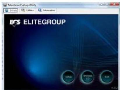

If the opening screen does not appear; double-click the file "setup.exe" in the root directory.
Using the Motherboard Software
Drivers Tab
| Setup | Click the Setup button to run the software installation program.Select from the menu which software you want to install. |
| Browse CD | The Browse CD button is the standard Windows command that allows you to open Windows Explorer and show the contents of the support disk.Before installing the software from Windows Explorer, look for a file named README.TXT or something similar. This file may contain important information to help you install the software correctly.Some software is installed in separate folders for different operating systems, such as Windows Vista/7. Always go to the correct folder for the kind of OS you are using.In install the software, execute a file named SETUP.EXE by double-clicking the file and then following the instructions on the screen. |
| Exit | The Exit button closes the Auto Setup window. |
Utilities Tab
Lists the software utilities that are available on the disk.
Information Tab
Displays the path for all software and drivers available on the disk.
Running Setup
Follow these instructions to install device drivers and software for the motherboard:
- Click Setup. The installation program begins:
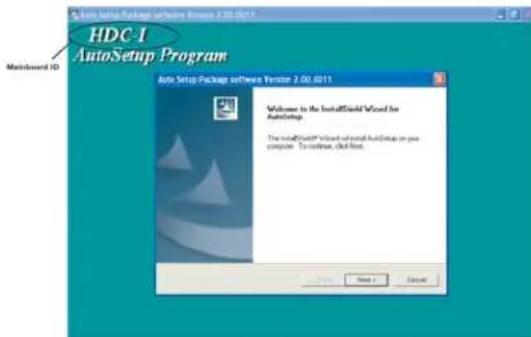

The following screens are examples only. The screens and driver lists will be different according to the motherboard you are installing.
The motherboard identification is located in the upper left-hand corner.
Using the Motherboard Software
- Click Next. The following screen appears:
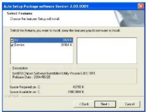
- Check the box next to the items you want to install. The default options are recommended.
- Click Next run the Installation Wizard. An item installation screen appears:

- Follow the instructions on the screen to install the items.

Drivers and software are automatically installed in sequence. Follow the onscreen instructions, confirm commands and allow the computer to restart a few times to complete the installation.
Using the Motherboard Software

Windows Vista/7 will appear below UAC (User Account Control) message after the system restart. You must select "Allow" to install the next driver. Continue this process to complete the drivers installation.

Manual Installation
Insert the disk in the DVD-ROM/CD-ROM drive and locate the PATH.DOC file in the root directory. This file contains the information needed to locate the drivers for your motherboard.
Look for the chipset and motherboard model; then browse to the directory and path to begin installing the drivers. Most drivers have a setup program (SETUP.EXE) that automatically detects your operating system before installation. Other drivers have the setup program located in the operating system subfolder.
If the driver you want to install does not have a setup program, browse to the operating system subfolder and locate the readme text file (README.TXT or README.DOC) for information on installing the driver or software for your operating system.
Utility Software Reference
All the utility software available from this page is Windows compliant. They are provided only for the convenience of the customer. The following software is furnished under license and may only be used or copied in accordance with the terms of the license.

These software(s) are subject to change at anytime without prior notice. Please refer to the support disk for available software.
This concludes Chapter 4.
Using the Motherboard Software
Chapter 5
Trouble Shooting
Start up problems during assembly
After assembling the PC for the first time you may experience some start up problems. Before calling for technical support or returning for warranty, this chapter may help to address some of the common questions using some basic troubleshooting tips.
a) System does not power up and the fans are not running.
- Disassemble the PC to remove the VGA adaptor card, DDR memory, LAN, USB and other peripherals including keyboard and mouse. Leave only the motherboard, CPU with CPU cooler and power supply connected. Turn on again to see if the CPU and power supply fans are running.
- Make sure to remove any unused screws or other metal objects such as screwdrivers from the inside PC case. This is to prevent damage from short circuit.
- Check the CPU FAN connector is connected to the motherboard.
- For Intel platforms check the pins on the CPU socket for damage or bent. A bent pin may cause failure to boot and sometimes permanent damage from short circuit.
- Check the 12V power connector is connected to the motherboard.
- Check that the 12V power & ATX connectors are fully inserted into the motherboard connectors. Make sure the latches of the cable and connector are locked into place.
b) Power is on, fans are running but there is no display
- Make sure the monitor is turned on and the monitor cable is properly connected to the PC.
- Check the VGA adapter card (if applicable) is inserted properly.
- Listen for beep sounds. If you are using internal PC speaker make sure it is connected.
a. continuous 3 short beeps : memory not detected
b. 1 long beep and 8 short beeps : VGA not detected
c) The PC suddenly shuts down while booting up.
-
The CPU may experience overheating so it will shutdown to protect itself. Ensure the CPU fan is working properly.
-
From the BIOS setting, try to disable the Smartfan function to let the fan run at default speed. Doing a Load Optimised Default will also disable the Smartfan.
Start up problems after prolong use
After a prolong period of use your PC may experience start up problems again. This may be caused by breakdown of devices connected to the motherboard such as HDD, CPU fan, etc. The following tips may help to revive the PC or identify the cause of failure.
- Clear the CMOS values using the CLR_CMOS jumper. Refer to CLR_CMOS jumper in Chapter 2 for Checking Jumper Settings in this user manual. When completed, follow up with a Load Optimised Default in the BIOS setup.
- Check the CPU cooler fan for dust. Long term accumulation of dust will reduce its effectiveness to cool the processor. Clean the cooler or replace a new one if necessary.
- Check that the 12V power & ATX connectors are fully inserted into the motherboard connectors. Make sure the latches of the cable and connector are locked into place.
- Remove the hard drive, optical drive or DDR memory to determine which of these component may be at fault.
Maintenance and care tips
Your computer, like any electrical appliance, requires proper care and maintenance. Here are some basic PC care tips to help prolong the life of the motherboard and keep it running as best as it can.
- Keep your computer in a well ventilated area. Leave some space between the PC and the wall for sufficient airflow.
- Keep your computer in a cool dry place. Avoid dusty areas, direct sunlight and areas of high moisture content.
- Routinely clean the CPU cooler fan to remove dust and hair.
- In places of hot and humid weather you should turn on your computer once every other week to circulate the air and prevent damage from humidity.
- Add more memory to your computer if possible. This not only speeds up the system but also reduces the loading of your hard drive to prolong its lifespan.
- If possible, ensure the power cord has an earth ground pin directly from the wall outlet. This will reduce voltage fluctuation that may damage sensitive devices.
Basic Troubleshooting Flowchart
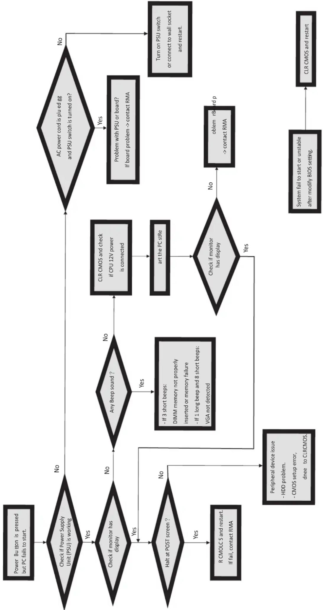
flowchart
graph TD
    A["Power Button is pressed but PC fails to start."] --> B{Check if Power Supply Unit (PSU) is working}
    B -->|No| C{AC power cord is plu ed gg and PSU switch is turned on?}
    B -->|Yes| D{Check if monitor has display}
    D -->|Yes| E{Any Beep sound ?}
    D -->|No| F{Halt at POST screen ?}
    F -->|Yes| G["R CMOLC S and restart. If fail, contact RMA"]
    F -->|No| H{>| Check if monitor has display |
    H -->|Yes| I["Peripheral device issue - HDD problem.<br>- CMOS setup error,<br>dnee to CLRCMOS."]
    H -->|No| J{- If 3 short beeps:
DIMM memory not properly
inserted or memory failure
- If 1 long beep and 8 short beeps:
VGA not detected}
    J --> K["ART THE PC stRe"]
    K --> L{Check if monitor has display}
    L -->|No| M["problem rBoard p --> contact RMA"]
    L -->|Yes| N["OR: System fail to start or unstable after modify BIOS setting."]
    C --> O{Problem with PSU or board?
If board problem --> contact RMA}
    O --> P["Turn on PSU switch or connect to wall socket and restart."]
    C --> Q{AC power cord is plu ed gg and PSU switch is turned on?}
    Q -->|No| R["OR: System fail to start or unstable after modify BIOS setting."]
    Q -->|Yes| S["OR: Problem with PSU or board?<br>If board problem --> contact RMA"]
    S --> T["OR: Turn on PSU switch or connect to wall socket and restart."]
    T --> U["OR: System fail to start or unstable after modify BIOS setting."]
    U --> V["OR: System fail to start or unstable after modify BIOS setting."]
Memo


- Disclaimer
- Trademark Recognition
- Federal Communications Commission (FCC)
- Preface
- TABLE OF CONTENTSABLE OF CONTENTS
- Chapter 11
- Introducing the Motherboard 1
- Chapter 2 7
- Installing the Motherboard 7
- Chapter 3 21
- Using BIOS 21
- Using the Motherboard Software 41
- Trouble Shooting 45
- Introduction
- Feature
- Processor
- Chipset
- Memory
- Onboard LAN(Optional)
- Audio
- Expansion Options
- Integrated I/O
- BIOS Firmware
- Chapter 2 Installing the Motherboard
- Safety Precautions
- Choosing a Computer Case
- Installing the Motherboard in a Case
- Checking Jumper Settings
- Setting Jumpers
- Installing Hardware
- Installing Memory Modules
- DDR3 SDRAM memory module table
- Installation Procedure
- Expansion Slots
- Installing Add-on Cards
- Installing the Motherboard
- Connecting Optional Devices
- SATA1\~4: Serial ATA III connectors
- F\_AUDIO: Front Panel Audio header for Azalia
- F\_USB1\~2: Front Panel USB 2.0 headers (F\_USB1 supports EZ charger)
- CASE: Chassis Intrusion Header
- Installing a SATA Hard Drive
- About SATA Connectors
- Installing Serial ATA Hard Drives
- Connecting I/O Devices
- Optical SPDIF
- Output
- Audio Ports
- Connecting Case Components
- Connecting 24-pin power cable
- Front Panel Header
- Hard Drive Activity LED
- Power/Sleep/Message waiting LED
- Reset Switch
- Power Switch
- Chapter 3
- Using BIOS
- About the Setup Utility
- The Standard Configuration
- Entering the Setup Utility
- Resetting the Default CMOS Values
- BIOS Navigation Keys
- Main Menu
- Date & Time
- Advanced Menu
- Launch PXE OpROM
- Launch Storage OpROM (Disabled)
- ECS eJIFFY Function
- ECS eJIFFY Function (Disabled)
- LAN Configuration
- Onboard LAN Controller (Enabled)
- PC Health Status
- ▶Smart Fan Function
- CPU Smart FAN Control (Enabled)
- Smart Fan Mode (Normal)
- SYS Smart Fan Control (Enabled)
- System Component Characteristics
- Power Management Setup
- Resume By PME (Enabled)
- Resume By USB (S3) (Disabled)
- EUP Support (Enabled)
- ACPI Configuration
- ACPI Sleep State (S3(Suspend to RAM))
- CPU Configuration
- SATA Configuration
- Onchip SATA Channel (Enabled)
- SATA Mode (IDE)
- SATA Port1\~4 (Not Present/ST380013AS)
- External SATA Port (Not Present)
- USB Configuration
- All USB Devices (Enabled)
- Legacy USB Support (Enabled)
- USB 3.0 Controller (Enabled)
- Onboard Bluetooth (Enabled)
- Chipset Menu
- ▶ North Bridge
- IGD Memory (Auto)
- Azalia Internal HDMI codec (Enabled)
- ▶ South Bridge
- Restore AC Power Loss (Power Off)
- Azalia HD Audio (Enabled)
- Case Open Warning (Disabled)
- Chassis Opened (No)
- Frequency/Voltage Control Menu
- Memory Clock (Auto)
- Memory Mode (Auto)
- CAS# Latency (tCL) (8CLK)
- RAS# to CAS# Delay(tRCD) (8CLK)
- Row Precharge Time(tRP) (8CLK)
- RAS# Active Time(tRAS) (20CLK)
- Boot Menu
- Boot Configuration
- Bootup NumLock State (On)
- Boot Option Priorities
- Security Menu
- Administrator Password
- Save & Exit Menu
- Save Changes and Exit
- Discard Changes and Exit
- Save Changes and Reset
- Discard Changes and Reset
- Save Options
- Save Changes
- Discard Changes
- Restore Defaults
- Save as User Defaults
- Boot Override
- SATA/UEFI/Launch EFI Shell from filesystem device
- Updating the BIOS
- Chapter 4 Using the Motherboard Software
- About the Software DVD-ROM/CD-ROM
- Auto-installing under Windows Vista/7
- Using the Motherboard Software
- Utilities Tab
- Information Tab
- Running Setup
- Manual Installation
- Utility Software Reference
- Chapter 5
- Trouble Shooting
- Start up problems during assembly
- a) System does not power up and the fans are not running.
- b) Power is on, fans are running but there is no display
- c) The PC suddenly shuts down while booting up.
- Start up problems after prolong use
- Maintenance and care tips
Brand : ECS
Model : HDC-I/E-240
Category : Tablet