GTT18FBMCC - Fridge GE - Free user manual and instructions
Find the device manual for free GTT18FBMCC GE in PDF.

User questions about GTT18FBMCC GE
0 question about this device. Answer the ones you know or ask your own.
Ask a new question about this device
Download the instructions for your Fridge in PDF format for free! Find your manual GTT18FBMCC - GE and take your electronic device back in hand. On this page are published all the documents necessary for the use of your device. GTT18FBMCC by GE.
USER MANUAL GTT18FBMCC GE
Connecting Electricity .... 3
Extension Cords 2
Safety Precautions 2
Operating Instructions
Automatic Icemaker ....8
Care and Cleaning ..... 9, 10
Shelves 5,6
Storage Drawers....6,7
Temperature Controls ....4
Installation Instructions
Preparing to Install
the Refrigerator ..... 11
Reversing the Door Swing ... 15–21
Water Line Installation ..... 12–15
Troubleshooting Tips
Before You Call for Service . . .22-24
Normal Operating Sounds .....22
Owner's Manual and Installation Instructions
Models
15, 16, 17, 18
Write the model and serial numbers here:
Model #
Serial #
You can find them on a label on the upper left side of the fresh food compartment.
⚠ WARNING!
Use this appliance only for its intended purpose as described in this Owner's Manual.
SAFETY PRECAUTIONS

When using electrical appliances, basic safety precautions should be followed, including the following:
This refrigerator must be properly installed and located in accordance with the Installation Instructions before it is used. Also see the How To Connect Electricity section.
Do not attempt to stand on top of the refrigerator. Doing so may result in bodily injury or damage to the refrigerator.
Do not allow children to climb, stand or hang on the shelves in the refrigerator. They could damage the refrigerator and seriously injure themselves.
Do not allow children to play with the refrigerator or tamper with the controls.
- Do not touch the cold surfaces in the freezer compartment when hands are damp or wet. Skin may stick to these extremely cold surfaces.
Do not store or use gasoline or other flammable vapors and liquids in the vicinity of this or any other appliance.
- Keep fingers out of the “pinch point” areas; clearances between the doors and between
the doors and cabinet are necessarily small. Be careful closing doors when children are in the area.
In refrigerators with automatic icemakers, avoid contact with the moving parts of the ejector mechanism, or with the heating element that releases the cubes. Do not place fingers or hands on the automatic icemaking mechanism while the refrigerator is plugged in.
■ Unplug the refrigerator before cleaning and making repairs.
NOTE: We strongly recommend that any servicing be performed by a qualified individual.
Before replacing a burned-out light bulb, the refrigerator should be unplugged in order to avoid contact with a live wire filament. (A burned-out light bulb may break when being replaced.)
NOTE: Turning the control to the 0 position does not remove power to the light circuit.
Do not refreeze frozen foods which have thawed completely.
▲ DANGER! RISK OF CHILD ENTRAPMENT
PROPER DISPOSAL OF THE REFRIGERATOR
Child entrapment and suffocation are not problems of the past. Junked or abandoned refrigerators are still dangerous...even if they will sit for “just a few days.” If you are getting rid of your old refrigerator, please follow the instructions below to help prevent accidents.
Before You Throw Away Your Old Refrigerator or Freezer:
Take off the doors and discard separately.
Leave the shelves in place so that children may not easily climb inside.
If the refrigerator has a lock make it unusable.
Refrigerants
All refrigeration products contain refrigerants, which under federal law must be removed prior to product disposal. If you are getting rid of an old refrigeration product, check with the company handling the disposal about what to do.

USE OF EXTENSION CORDS
Because of potential safety hazards under certain conditions, we strongly recommend against the use of an extension cord.
However, if you must use an extension cord, it is absolutely necessary that it be a UL-listed, 3-wire grounding type appliance extension cord having a grounding type plug and outlet and that the electrical rating of the cord be 15 amperes (minimum) and 120 volts.

⚠ WARNING!
HOW TO CONNECT ELECTRICITY
Do not, under any circumstances, cut or remove the third (ground) prong from the power cord. For personal safety, this appliance must be properly grounded.
The power cord of this appliance is equipped with a 3-prong (grounding) plug which mates with a standard 3-prong (grounding) wall outlet to minimize the possibility of electric shock hazard from this appliance.
Have the wall outlet and circuit checked by a qualified electrician to make sure the outlet is properly grounded.
Where an ungrounded wall outlet is encountered, it is your personal responsibility and obligation to have it replaced with a properly grounded 3-prong wall outlet.
The refrigerator should always be plugged into its own individual electrical outlet. This provides the best performance and also prevents overloading house wiring circuits which could cause a fire hazard from overheated wires. Please refer to the rating plate on the refrigerator for the correct voltage, wattage and frequency. If the product plug does not fit your outlet, the product should be fitted with a new plug.

text_image
Insure proper grou exists before usingIMPORTANT: The refitting of electric plugs and cables should be done by a qualified technician or service agent. In some countries the refitting of electric plugs and cables is only permitted when the work is completed by a qualified technician. If the power supply cord becomes damaged, it must be replaced by a qualified service agent in order to avoid a safety hazard.
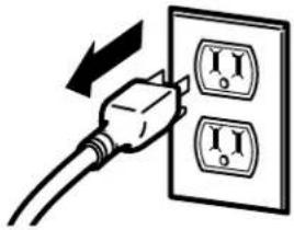
Never unplug your refrigerator by pulling on the power cord. Always grip plug firmly and pull straight out from the outlet.
Repair or replace immediately all power cords that have become frayed or otherwise damaged. Do not use a cord that shows cracks or abrasion damage along its length or at either end.
When moving the refrigerator away from the wall, be careful not to roll over or damage the power cord.
Mains Lead Replacement
If the mains lead on your refrigerator needs replacing at any time, it must be replaced by a special lead which is obtainable from your local dealer. A charge will be made for the replacement of the mains lead if you have damaged the lead.

USE OF ADAPTER PLUGS
Because of potential safety hazards under certain conditions, we strongly recommend against the use of an adapter plug.
However, if you must use an adapter, where local codes permit, a temporary connection may be made to a properly grounded 2-prong wall outlet by use of a UI-listed adapter available at most local hardware stores.
The larger slot in the adapter must be aligned with the larger slot in the wall outlet to provide proper polarity in the connection of the power cord.
When disconnecting the power cord from the adapter, always hold the adapter in place with one hand while pulling the power cord plug with the other hand. If this is not done, the adapter ground terminal is very likely to break with repeated use.
If the adapter ground terminal breaks, DO NOT USE the refrigerator until a proper ground has been established.
Attaching the adapter ground terminal to a wall outlet cover screw does not ground the appliance unless the cover screw is metal, and not insulated, and the wall outlet is grounded through the house wiring. You should have the circuit checked by a qualified electrician to make sure the outlet is properly grounded.

READ AND FOLLOW THIS SAFETY INFORMATION CAREFULLY.
SAVE THESE INSTRUCTIONS
About the temperature control dial.
Turning the dial to 0 stops cooling in both compartments—fresh food and freezer. It does not shut off power to the refrigerator.

text_image
0 6 7 5 3 1
Control Settings
Temperature Control Dial
The temperature control dial has nine settings plus 0.1 is the warmest. 9 is the coldest. At first, set the dial at 5.
After using the refrigerator, adjust the dial if necessary.
Insert a coin into the slot in the middle of the dial and you can turn the dial to the setting that's best suited to your needs.
Allow 24 hours for the refrigerator to get cold.

text_image
1 ◀ ▷ 0Anti-Condensation Switch (on some models)
If moisture develops on the ceiling of the fresh food compartment, turn the anti-condensation switch to the 1 (on) position. Moisture is likely to appear when the air is humid—in the summer, in the early morning hours or in non-air conditioned rooms. Move to the 0 (OFF) position in less humid conditions.
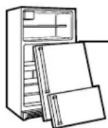
About the fresh food compartment shelves.
Shelf supports at various levels allow you to custom-space your shelves. Not all features are on all models.
text_image
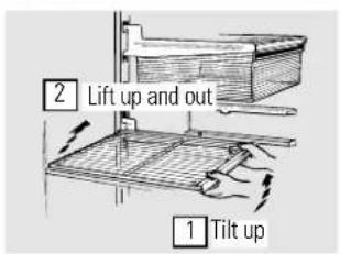
2 Lift up and out 1 Tilt upHalf-Width Shelves
One end of the shelf rests on a molded sidewall support; a bracket on the other end hooks into a track on the rear cabinet wall.
NOTE: The shelf to the right of the track is designed to hook into the right-hand slot; the shelf to the left is designed to hook into the left-hand slot.
natural_image
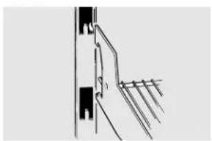
Pure mechanical diagram showing a bracket and guide rail (no text or symbols)To remove, lift the shelf up at front, then off the support and out of the track.
To replace, select desired shelf height. With shelf front raised slightly, hook the bracket's top lug into the track, then lower the shelf onto the support.
natural_image
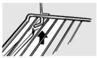
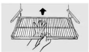
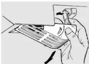
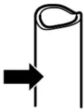
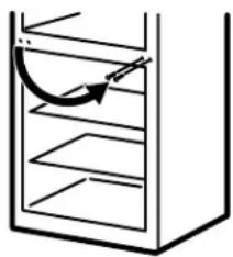
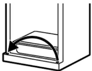
Diagram of a metal grate with a curved arrow indicating direction (no text or symbols)Full-Width Shelves
Some models have a steel wire sliding shelf, a stationary tempered glass shelf or two steel wire stationary shelves. These shelves can be moved to another place in the fresh food compartment.
The full-width sliding shelf has stop-locks. When placed correctly on the shelf supports, the shelf will stop before coming completely out of the refrigerator and will not tilt when you place food on it or remove food from it.
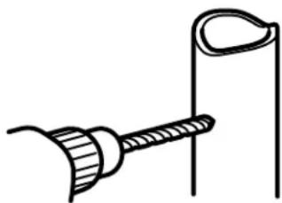
natural_image
Illustration of hands holding a metal tray with a black arrow indicating upward motion (no text or symbols)To remove the full-width shelves, lift the rear of the shelf and pull forward.

natural_image
Diagram of a hand holding a metal tray with arrows indicating rotation or movement (no text or symbols)To remove a full-width shelf when the fresh food compartment door cannot be opened fully, lift the rear of the shelf, pull forward and down, tilt the shelf and take it out.
About the frozen food compartment shelves.
Some models have an ice-tray shelf and some have a full-width step shelf.
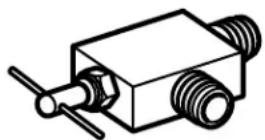
text_image
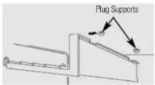
Plug SupportsIce-Tray Shelf
To remove the ice-tray shelf, lift the left side of the shelf off its supports, then pull the shelf to the left to free it of the plug supports.
Pull the shelf to the right to free the pins from the holes in the cabinet wall.
text_image
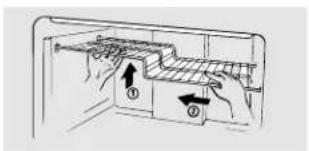
Diagram showing a mechanical or electrical component with labeled parts and directional arrows indicating movement or force.Step Shelf
To remove the step shelf:
7 Lift left side of shelf slightly.
2 Move shelf to the left to free its right ends from holes in the cabinet wall.
3 Lower right side of shelf, move shelf to the right and take it out.
natural_image
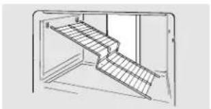
Line drawing of a staircase with stairs and windows (no text or symbols)To replace the step shelf:
With shelf tilted as shown, fit left ends of shelf into holes in cabinet wall.

natural_image
Line drawing of a hand inserting a component into a storage cabinet (no text or symbols)2 Lift left side of shelf slightly, swing shelf up, fit right ends of shelf into holes in cabinet wall, and lower shelf into place.

natural_image
Illustration of hands holding a small object with scattered cubes (no text or symbols)Ice Trays (on some models)
Ice trays are designed to release ice cubes easily. Hold tray upside-down over a container and twist both ends to release cubes.
For only one or two ice cubes, leave the tray right-side up, twist both ends slightly and remove desired number of cubes. Wash ice trays and storage bin in lukewarm water only. Do not put them in an automatic dishwasher.

natural_image
Simple line drawing of a mechanical component with a curved tool inserted (no text or symbols)About the storage drawers.
Not all features are on all models.
natural_image
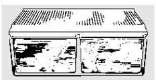
Simple line drawing of a two-compartment container with lid and side compartments (no text or symbols)Fruit and Vegetable Drawers
Excess water that may accumulate in the bottom of the drawers should be emptied and the drawers wiped dry.
natural_image
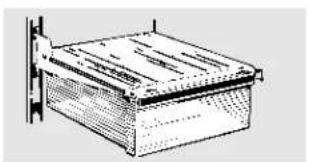
Technical line drawing of a rectangular box mounted on a vertical wall (no text or symbols)Snacks Drawer
This drawer can be moved to the most useful location for your family's needs.
About storage drawer and cover removal.
Not all features are on all models.
Drawer and Cover Removal
Drawers can be removed easily by grasping the sides and lifting up slightly while pulling drawers past the stop location.
natural_image
Simple line drawing of a hand placing a document into a laptop (no text or symbols visible)Full-Width Drawer with Plastic Cover
To remove the cover, lift it off its supports, pull it forward, tilt it and take it out.

natural_image
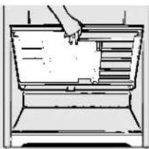
Simple line drawing of a vehicle chassis with no text or symbolsTwin Drawers with Glass Cover
To remove:
Remove the drawers.
2 Reach in, push the front of glass cover up, and at the same time, pull it forward as far as it will come.
Tilt it and take it out. Avoid cleaning the cold glass cover with hot water because the extreme temperature difference may cause it to break.
3 Remove the drawer frame. (Always remove the glass cover before you take out the drawer frame.)
Lift the frame off the supports at each side and back, pull it forward, tilt it and take it out.
To replace:
1 Lower the frame until it rests on the supports at each side and back.
2 Replace the glass cover, pushing its rear edge firmly into the rear frame channel and gently lowering the front into place.
3 Replace the drawers.
A newly-installed refrigerator may take 12 to 24 hours to begin making ice.

text_image
Power Switch Green Power Light Feeler Arm IcemakerPower switch model
text_image
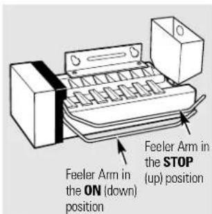
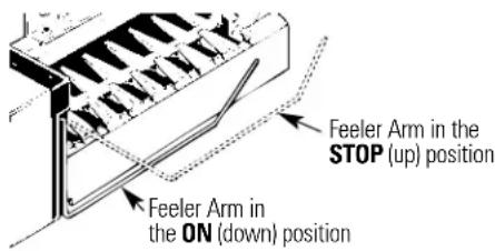
Feeler Arm in the ON (down) position Feeler Arm in the STOP (up) positionFeeler arm model
Automatic Icemaker (on some models)
The icemaker will produce seven cubes per cycle—approximately 100–130 cubes in a 24-hour period, depending on freezer compartment temperature, room temperature, number of door openings and other use conditions.
There are two types of icemakers: power switch models and feeler arm models.
If the refrigerator is operated before the water connection is made to the icemaker, set the power switch to O (off) or move the feeler arm to the STOP (up) position.
When the refrigerator has been connected to the water supply, set the power switch to the I (on) position or move the feeler arm to the ON (down) position. On power switch models, the green light will come on.
The icemaker will fill with water when it cools to 15^ F ( -9^ C). A newly-installed refrigerator may take 12 to 24 hours to begin making ice cubes.
You will hear a buzzing sound each time the icemaker fills with water.
Throw away the first few batches of ice to allow the water line to clear.
Be sure nothing interferes with the sweep of the feeler arm.
When the bin fills to the level of the feeler arm, the icemaker will stop producing ice.
It is normal for several cubes to be joined together.
If ice is not used frequently, old ice cubes will become cloudy, taste stale and shrink.
On power switch models, the green power light will blink if ice cubes get stuck in the icemaker. To correct this, set the power switch to 0 (off) and remove the cubes. Set the power switch to I (on) to restart the icemaker. After the icemaker has been turned on again, there will be a delay of about 45 minutes before the icemaker resumes operation.
NOTE: In homes with lower-than-average water pressure, you may hear the icemaker cycle multiple times when making one batch of ice.
Icemaker Accessory Kit
If your refrigerator did not already come equipped with an automatic icemaker, an icemaker accessory kit is available at extra cost.
Check the back of the refrigerator for the specific icemaker kit needed for your model.
Care and cleaning of the refrigerator.
Cleaning the Outside
The door handles and trim (on some models). Clean with a cloth dampened with soapy water. Dry with a soft cloth.
Keep the outside clean. Wipe with a clean cloth lightly dampened with kitchen appliance wax or mild liquid dish detergent. Dry and polish with a clean, soft cloth.
Do not wipe the refrigerator with a soiled dish cloth or wet towel. These may leave a residue that can erode the paint. Do not use scouring pads, powdered cleaners, bleach or cleaners containing bleach because these products can scratch and weaken the paint finish.
Cleaning the Inside
To help prevent odors, leave an open box of baking soda in the fresh food and freezer compartments.
Unplug the refrigerator before cleaning.
If this is not practical, wring excess moisture out of sponge or cloth when cleaning around switches, lights or controls.
Use warm water and baking soda solution—about a tablespoon (15 ml) of baking soda to a quart (1 liter) of water. This both cleans and neutralizes odors. Rinse and wipe dry.
After cleaning the door gaskets, apply a thin layer of petroleum jelly to the door gaskets at the hinge side. This helps keep the gaskets from sticking and bending out of shape.
Avoid cleaning cold glass shelves (on some models) with hot water because the extreme temperature difference may cause them to break. Handle glass shelves carefully. Bumping tempered glass can cause it to shatter.
Do not wash any plastic refrigerator parts in the dishwasher.
natural_image
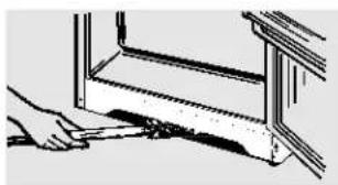
Illustration of a hand cleaning or adjusting a window frame (no text or symbols visible)Cleaning the condenser coils.
Condenser
There is no need for routine condenser cleaning in normal home operating environments. However, in environments that may be particularly dusty or greasy, the condenser should be cleaned periodically for efficient refrigerator operation.
To clean the condenser, turn the temperature control dial to 0. Sweep away or vacuum up dust.
For best results, use a brush specially designed for this purpose. It is available at most appliance parts stores.
natural_image
Illustration of a hand holding a card with a clip, no text or symbols presentSqueeze to release the hook.
Light Bulb Replacement (on some models)
A light bulb and socket are located at the top of the fresh food compartment opposite the temperature control panel.
To replace the bulb, first unplug the refrigerator from its electrical outlet. Put your hand under the light shield and release the hook at the bulb end of the shield. (The light shield is on some models.)
Care and cleaning of the refrigerator.
Behind the Refrigerator
Be careful when moving the refrigerator away from the wall. All types of floor coverings can be damaged, particularly cushioned coverings and those with embossed surfaces.
Turn the leveling legs at each front corner of the refrigerator counterclockwise until the rollers support the refrigerator. Pull the refrigerator straight out and return it to position by pushing it straight in. Moving the refrigerator in a side direction may result in damage to the floor covering or refrigerator.
When pushing the refrigerator back, make sure you don't roll over the power cord or icemaker supply line (on some models).
After rolling the refrigerator back into place, turn the legs clockwise until the legs again bear the weight of the refrigerator.
Preparing for Vacation
For long vacations or absences, remove food and unplug the refrigerator. Move the temperature control dial to the 0 position, and clean the interior with a baking soda solution of one tablespoon (15 ml) of baking soda to one quart (1 liter) of water. Leave the doors open.
Set the icemaker power switch to the 0 (off) position or move the feeler arm to the STOP (up) position (depending on model) and shut off the water supply to the refrigerator.
If the temperature can drop below freezing, have a qualified servicer drain the water supply system (on some models) to prevent serious property damage due to flooding.
Preparing to Move
Secure all loose items such as grille, shelves and drawers by taping them securely in place to prevent damage.
Be sure the refrigerator stays in an upright position during moving.
Installation Instructions
Refrigerator
Models 15, 16, 17 and 18
BEFORE YOU BEGIN
Read these instructions completely and carefully.
- IMPORTANT – Save these instructions for local inspector's use.
- IMPORTANT – Observe all governing codes and ordinances.
- Note to Installer – Be sure to leave these instructions with the Consumer.
- Note to Consumer – Keep these instructions for future reference.
- Skill level – Installation of this appliance requires basic mechanical skills.
- Completion time – Refrigerator Installation 15 minutes Reversing the Door Swing 1 hour
- Proper installation is the responsibility of the installer.
- Product failure due to improper installation is not covered under the Warranty.
DIMENSIONS
Model 15 16 17 18
| A* | 61" (155 cm) | 64" (163 cm) | 67" (170 cm) | 67" (170 cm) |
| B | 28" (71 cm) | 28" (71 cm) | 28" (71 cm) | 28" (71 cm) |
| C** | 31 ^1 / _10 " (79 cm) | 31 ^1 / _10 " (79 cm) | 32 ^1 / _4 " (81 cm) | 32 ^2 / _3 " (82 cm) |
| D | 54 ^7 / _10 " (139 cm) | 54 ^7 / _10 " (139 cm) | 56" (142 cm) | 56 ^3 / _8 " (143 cm) |
| E | 26" (66 cm) | 26" (66 cm) | 26 ^7 / _8 " (68 cm) | 26 ^7 / _8 " (68 cm) |
* Height does not include hinge—Add 22 mm for hinge. ** Depth includes handle.

text_image
A B C D EWATER SUPPLY TO THE ICEMAKER (on some models)
If the refrigerator has an icemaker, it will have to be connected to a cold drinking water line. A water supply kit (containing copper tubing, shutoff valve, fittings and instructions) is available at extra cost from your dealer. Installation of the icemaker must be done by a qualified service technician.
REFRIGERATOR LOCATION
- Do not install the refrigerator where the temperature will go below 60^ (16°C) because it will not run often enough to maintain proper temperatures.
• Install it on a floor strong enough to support it fully loaded.
CLEARANCES
Allow the following clearances for ease of installation, proper air circulation and plumbing and electrical connections.
- Sides 3 / 4'' (19 mm)
- Top 1'' (25 mm)
- Back 1" (25 mm)
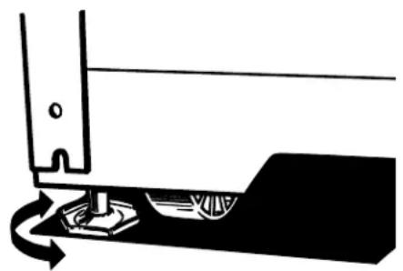
Leveling legs near each front corner of the refrigerator are adjustable. They firmly position the refrigerator and prevent it from moving when the doors are opened. Leveling legs should be set so the front of the refrigerator is raised just enough that the doors close easily when opened about halfway.
Turn the leveling legs clockwise to raise the refrigerator, counterclockwise to lower it.
Rollers next to the leveling legs allow you to move the refrigerator away from the wall for cleaning.
Turn the legs counterclockwise until the weight of the refrigerator is transferred from them to the rollers. After rolling the refrigerator back into place, turn the legs clockwise until the legs again bear the weight of the refrigerator.
natural_image
Pure mechanical diagram showing a tool interacting with a base, no text or symbols present1 INSTALLING THE WATER LINE
BEFORE YOU BEGIN
This water line installation is not warranted by the refrigerator or icemaker manufacturer. Follow these instructions carefully to minimize the risk of expensive water damage.
Water hammer (water banging in the pipes) in house plumbing can cause damage to refrigerator parts and lead to water leakage or flooding. Call a qualified plumber to correct water hammer before installing the water supply line to the refrigerator.
To prevent burns and product damage, do not hook up the water line to the hot water line.
If you use your refrigerator before connecting the water line, make sure the icemaker power switch is in the OFF position (on power switch models) or the feeler arm is in the STOP (up) position (on feeler arm models).
Do not install the icemaker tubing in areas where temperatures fall below freezing.
When using any electrical device (such as a power drill) during installation, be sure the device is insulated or wired in a manner to prevent the hazard of electric shock.
All installations must be in accordance with local plumbing code requirements.
Installation of the icemaker must be done by a qualified service technician.
WARNING!
Connect to potable
water supply only.
WHAT YOU WILL NEED
To determine how much copper tubing you need:
Measure the distance from the water valve on the back of the refrigerator to the water supply pipe. Then add 8 feet (244 cm). Be sure there is sufficient extra tubing [about 8 feet (244 cm) coiled into 3 turns of about 10" (25 cm) diameter] to allow the refrigerator to move out from the wall after installation.
- A water supply kit (containing copper tubing, shutoff valve and fittings listed below) is available at extra cost from your local distributor.
- A cold drinking water supply. The water pressure must be between 20 and 120 p.s.i. (1.4–8.1 bar).
WHAT YOU WILL NEED (CONT.)

- Power drill.
natural_image
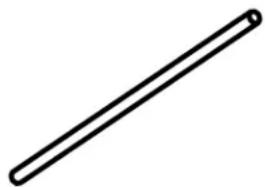
Simple line drawing of a straight rod or rod (no text or symbols)- Copper tubing, 1/4" outer diameter to connect the refrigerator to the water supply. Be sure both ends of the tubing are cut square.
Do not use plastic tubing or plastic fittings because the water supply line is under pressure at all times. Certain types of plastic tubing may become brittle with age and crack, resulting in water leakage.
natural_image
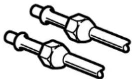
Technical line drawing of two mechanical fasteners (no text or symbols)- Two 1/4" outer diameter compression nuts and 2 ferrules (sleeves)—to connect the copper tubing to the shutoff valve and the refrigerator water valve.

- If your existing water line has a flared fitting at the end, you will need an adapter (available at plumbing supply stores) to connect the water line to the refrigerator OR you can cut off the flared fitting with a tube cutter and then use a compression fitting.
- Shutoff valve to connect to the cold water line. The shutoff valve should have a water inlet with a minimum inside diameter of 5/32" at the point of connection to the COLD WATER LINE. Saddle-type shutoff valves are included in many water supply kits. Before purchasing, make sure a saddle-type valve complies with your local plumbing codes.
Install the shutoff valve on the nearest frequently used drinking water line.
1 SHUT OFF THE MAIN WATER SUPPLY
Turn on the nearest faucet long enough to clear the line of water.
2 CHOOSE THE VALVE LOCATION
Choose a location for the valve that is easily accessible. It is best to connect into the side of a vertical water pipe. When it is necessary to connect into a horizontal water pipe, make the connection to the top or side, rather than at the bottom, to avoid drawing off any sediment from the water pipe.
natural_image
Simple line drawing of a curved pipe or tube with an arrow pointing to it (no text or symbols)3 DRILL THE HOLE FOR THE VALVE
Drill a 1/4"hole in the water pipe, using a sharp bit. Remove any burrs resulting from drilling the hole in the pipe.
natural_image
Simple line drawing of a tool or bracket with a curved handle and a vertical line (no text or symbols)4 FASTEN THE SHUTOFF VALVE
Fasten the shutoff valve to the cold water pipe with the pipe clamp.
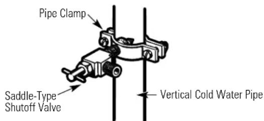
text_image
Pipe Clamp Saddle-Type Shutoff Valve Vertical Cold Water Pipe5 TIGHTEN THE PIPE CLAMP
Tighten the clamp screws until the sealing washer begins to swell.
NOTE: Do not overtighten or you may crush the copper tubing.
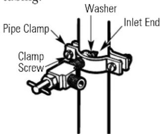
text_image
Pipe Clamp Clamp Screw Washer Inlet End6 ROUTE THE TUBING
Route the copper tubing between the cold water line and the refrigerator.
Route the tubing through a hole drilled in the wall or floor (behind the refrigerator or adjacent base cabinet) as close to the wall as possible.
NOTE: Be sure there is sufficient extra tubing [about 8 feet (244 cm) coiled into 3 turns of about 10"(25 cm) diameter] to allow the refrigerator to move out from the wall after installation.
1 INSTALLING THE WATER LINE (CONT.)
7 CONNECT THE TUBING TO THE VALVE
Place the compression nut and ferrule (sleeve) onto the end of the tubing and connect it to the shutoff valve.
Make sure the tubing is fully inserted into the valve. Tighten the compression nut securely.
Saddle-Type Shutoff Valve
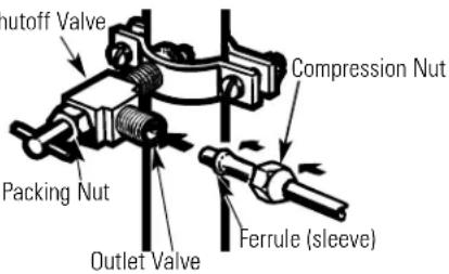
text_image
nutoff Valve Compression Nut Packing Nut Outlet Valve Ferrule (sleeve)8 FLUSH OUT THE TUBING
Turn the main water supply on and flush out the tubing until the water is clear.
Shut the water off at the water valve after about one quart (1 liter) of water has been flushed through the tubing.

natural_image
Simple line drawing of a flower with petals and a curved arrow, no text or symbols present9 CONNECT THE TUBING TO THE REFRIGERATOR
NOTES:
- Before making the connection to the refrigerator, be sure the refrigerator power cord is not plugged into the wall outlet.
- We recommend installing a water filter if your water supply has sand or particles that could clog the screen of the refrigerator's water valve. Install it in the water line near the refrigerator.
9 CONNECT THE TUBING TO THE REFRIGERATOR (CONT.)
9.1 Remove the access cover.

natural_image
Pure technical line drawing of a rectangular frame with mounting holes and internal ribs (no text or symbols)9.2 Remove the plastic flexible cap from the water valve.
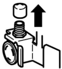
natural_image
Pure mechanical diagram showing a piston and cylinder assembly with an upward arrow, no text or symbols present.9.3 Place the compression nut and ferrule (sleeve) onto the end of the tubing as shown.
Insert the end of the copper tubing into the water valve connection as far as possible. While holding the tubing, tighten the fitting.
Fasten the copper tubing into the clamp provided to hold it in a vertical position. You may need to pry open the clamp.

text_image
1/4"Copper Tubing Tubing Clamp 1/4"Compression Nut Ferrule (sleeve) Refrigerator Connection9.4 Reattach the access cover.

natural_image
Pure technical diagram of a rectangular structural component with mounting holes and internal forces (no text or symbols)10 TURN THE WATER ON AT THE SHUTOFF VALVE
Tighten any connections that leak.

natural_image
Mechanical clamp mechanism diagram showing rotational motion (no text or symbols)11 PLUG IN THE REFRIGERATOR
Arrange the coil of copper tubing so that it does not vibrate against the back of the refrigerator or against the wall. Push the refrigerator back to the wall.

natural_image
Illustration of a hand inserting a plug into an electrical outlet (no text or symbols)12 START THE ICEMAKER
On power switch models, set the icemaker power switch to the I (on) position. On feeler arm models, move the feeler arm to the ON (down) position. The icemaker will not begin to operate until it reaches its operating temperature of 15^ F ( -9^ C) or below. It will then begin operation automatically.

text_image
Power switchPower switch model
text_image
Feeler Arm in the STOP (up) position Feeler Arm in the ON (down) positionFeeler arm model
NOTE: In lower water pressure conditions, the water valve may turn on up to 3 times to deliver enough water to the icemaker.
2 REVERSING THE DOOR SWING
IMPORTANT NOTES
When reversing the door swing:
- Read the instructions all the way through before starting.
- Handle parts carefully to avoid scratching paint.
- Set screws down by their related parts to avoid using them in the wrong places.
- Provide a non-scratching work surface for the doors.
IMPORTANT: Once you begin, do not move the cabinet until door-swing reversal is completed.
These instructions are for changing the hinges from the right side to the left side—if you ever want to change the hinges back to the right side, follow these same instructions and reverse all references to left and right.
TOOLS REQUIRED

Phillips screwdriver

Masking tape

5/16"hex-head socket driver
T20 or T25
Torxdriver,
(needed for
some models)

Putty knife or thin-blade screwdriver
5/16"open-end wrench
2 REVERSING THE DOOR SWING (CONT.)
1 BEFORE YOU START
1.1 Unplug the refrigerator from its electrical outlet.
natural_image
Hand inserting a plug into an electrical outlet (no text or symbols visible)1.2 Empty all door shelves, including the dairy compartment.

natural_image
Line drawing of an open refrigerator with multiple doors and shelves (no text or symbols)CAUTION: Do not let either door drop to the floor. To do so could damage the door stop.
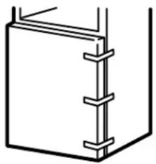
② REMOVE THE FROZEN FOOD COMPARTMENT DOOR
2.1 Tape the door shut with masking tape.
natural_image
Pure technical line drawing of a mechanical component with no text or symbols② REMOVE THE FROZEN FOOD COMPARTMENT DOOR (CONT.)
2.2 With a 5/16" hex-head socket driver, remove the screws that hold the top hinge to the cabinet.

natural_image
Technical line drawing of a mechanical assembly with no visible text or symbols2.3 Lift the hinge (and the shim glued to it) straight up to free the hinge pin from the socket in the top of the door and set it aside, along with its screws.
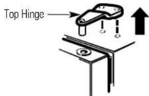
text_image
Top Hinge2.4 Remove the tape and tilt the door away from the cabinet. Lift it off the center hinge pin.
natural_image
Simple line drawing of a box with an open lid and an arrow indicating direction (no text or symbols)2.5 Set the door on a non-scratching surface with the outside up.

natural_image
Simple line drawing of a two-tiered rectangular block on a base (no text or symbols)2 REMOVE THE FROZEN FOOD COMPARTMENT DOOR (CONT.)
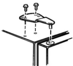
2.6 Transfer the 2 screws from the opposite side of the cabinet to the screw holes vacated by the top hinge removal.
natural_image
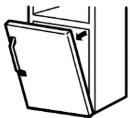
Simple line drawing of a cabinet with an arrow indicating rotation (no text or symbols)3 REMOVE THE FRESH FOOD DOOR
3.1 Tape the door shut with masking tape.
natural_image
Simple line drawing of a rectangular container with vertical connectors (no text or symbols)3.2 Using a 5/16" hex-head socket screwdriver and a 5/16" open-end wrench, remove the two screws holding the center hinge (and the shim glued to it) to the cabinet. Lift the center hinge to free its pin from the socket in the top of the door, and set hinge and screws aside. Be careful not to lose the center hinge spacer and washer.

natural_image
Technical line drawing of two mechanical components with bolts and brackets (no text or symbols)3.3 Remove the tape and tilt the door away from the cabinet. Lift the door from the pin in the bottom hinge bracket. (If the plastic washer sticks to the door bottom, put it back on the hinge.)
natural_image
Simple line drawing of a cabinet or cabinet with an open lid and handle (no text or symbols)3 REMOVE THE FRESH FOOD DOOR (CONT.)
3.4 Set the door outside-up on a non-scratching surface.
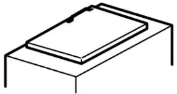
natural_image
Simple line drawing of a rectangular object on a base, no text or symbols present3.5 Transfer the two screws from the opposite side of the cabinet to the screw holes vacated by the center hinge removal.
natural_image
Simple line drawing of a container with horizontal shelves and an arrow indicating rotation (no text or symbols)3.6 Transfer the washer (if your model has one) to the opposite side.
natural_image
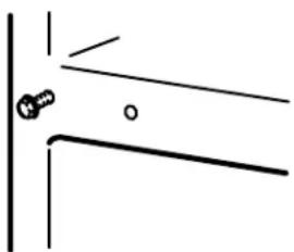
Simple line drawing of a container with an arrow indicating direction (no text or symbols)3.7 Take one of the screws removed in step 2 and start it in the outermost screw hole on the opposite side. Do not drive it all the way down—leave enough space under the screw head for thickness of shim and bracket.
natural_image
Simple line drawing of a mechanical joint or bracket with a bolt and circular end (no text or symbols)2 REVERSING THE DOOR SWING (CONT.)
4 REVERSING THE HARDWARE
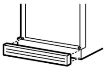
4.1 Remove the base grille (if your refrigerator has one) by pulling it straight out.
natural_image
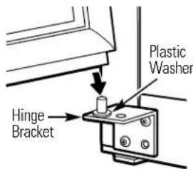
Pure technical line drawing of a structural bracket with no text or symbols4.2 Move the bottom hinge bracket (and shim glued to it) and plastic washer from the right side to the left side.
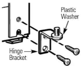
text_image
Plastic Washer Hinge BracketModels with a hinge bracket that has 2 screw holes.
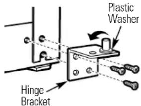
text_image
Plastic Washer Hinge BracketModels with a hinge bracket that has 4 screw holes. Switch the hinge pin to the opposite side of the bracket.
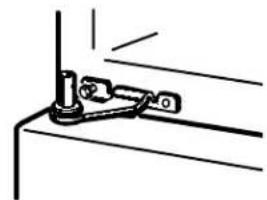
4.3 Interchange hinge (and the shim glued to it) and screws at top right with screws at top left of cabinet. Do not tighten screws on hinge side at this time.
natural_image
Pure mechanical assembly diagram showing two bolts and a bracket (no text or symbols)Installing the hinge on the left.

natural_image
Pure technical diagram of a mechanical bracket assembly without any text, numbers, or symbolsInstalling the hinge on the right.
NOTES:
- Some hinges have four holes. Which holes you use for installing the hinge depends on which side you install the hinge.
- The outer edge of the hinge should be parallel to the edge of the case for correct installation.
5 REVERSING THE DOOR HANDLES
5.1 Transfer fresh food door handle
5.1.1 Remove the bottom cap by pushing it toward the bottom of the door, and remove the screw underneath. Remove the two screws holding the handle to the top of the door.

natural_image
Simple line drawing of a rectangular object with a vertical line and small protrusions, no text or symbols present.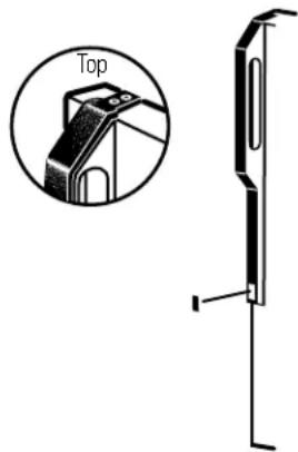
text_image
Top5.1.2 Remove the handle.
5.1.3 Remove the screws from the right edge of the door top and insert them into the handle screw holes on the opposite side.

text_image
Screws for Handle Holes5 REVERSING THE DOOR HANDLES (CONT.)
5.1 Transfer fresh food door handle (cont.)
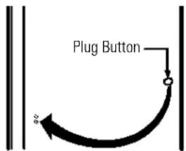
5.1.4 With tape-tipped putty knife or thin-blade screwdriver, pry out the plug button from the hinge hole on the left side of the door and insert it into the hole on the opposite side that was vacated by removal of the top hinge.

text_image
Plug Button5.1.5 Pull the plug button from the front of the door and transfer it to the opposite side.
text_image
Plug ButtonTo reattach the handle on the opposite side.
5.2 Transfer door stop
5.2.1 Move the metal door stop from the right end to the left end.

text_image
Door Stop Left Side5.2 Transfer door stop (cont.)
5.2.2 Move any screws from the left end to the right end.

text_image
Right Side5.3 Reinstalling the Fresh Food Door Handle
5.3.1 Attach the handle to the right side of the door with screws at the top and under the handle plug.

natural_image
Simple line drawing of a rectangular object with a vertical rod and protruding rod (no text or symbols)5.3.2 Reinstall the handle plug.

natural_image
Simple line drawing of a rectangular object with a vertical slot and an arrow pointing to it (no text or symbols)2 REVERSING THE DOOR SWING (CONT.)
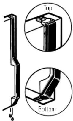
5.4 Transfer Frozen Food Compartment Door Handle
5.4.1 Remove the screw holding the handle to the top of the door and the two screws holding the handle to the bottom of the door.
text_image
Top Bottom5.4 Transfer Frozen Food Compartment Door Handle (cont.)
5.4.4 Transfer the door stop as shown on the preceding page.
5.4.5 Attach the handle to the right edge of the door with screws at top and bottom, using bottom holes vacated by removal of the door stop screws.
natural_image
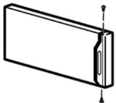
Simple line drawing of a rectangular object with a side protrusion and vertical alignment lines (no text or symbols)5.4.2 Remove the handle.
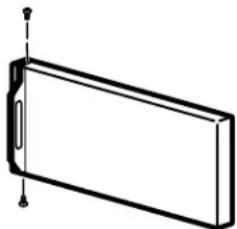
natural_image
Simple line drawing of a rectangular object with a vertical dimension line and a small protrusion at the top (no text or symbols)5.4.3 Remove the screw from the right top edge of the door and insert it into the handle screw hole on the left side.
natural_image
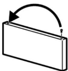
Simple 3D diagram of a rectangular block with an arrow indicating rotational motion (no text or symbols)6 REHANGING THE DOORS
6.1 Rehang the fresh food door
6.1.1 Lower the fresh food door onto the bottom hinge pin. Be sure the washer is in place on the pin.

text_image
Plastic Washer Hinge BracketModels with a hinge bracket that has 2 screw holes.
text_image
Plastic Washer Hinge BracketModels with a hinge bracket that has 4 screw holes.
6.1.2 Insert the pin on the center hinge into the socket in the top of the door. Place the spacer, then the washer, on the hinge pin. NOTE: The center hinge must be turned over as shown when mounted on the left side.
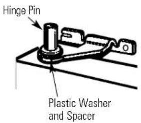
text_image
Hinge Pin Plastic Washer and Spacer6.1.3 Tilt the door toward the cabinet. As the door is brought into position, slide the hinge under the head of the screw which earlier had been partly driven into the outermost hole. Insert the remaining screw, then tighten both screws securely.
natural_image
Simple line drawing of a mechanical clamp or bracket assembly (no text or symbols)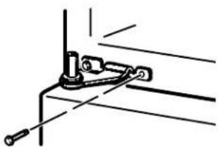
natural_image
Pure mechanical linkage diagram without any text, numbers, or symbols6 REHANGING THE DOORS (CONT.)
6.2 Rehang the frozen food compartment door
6.2.1 Lower the freezer door onto the center hinge pin. Be sure the washer and spacer are in place on the pin.
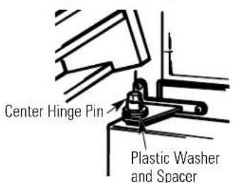
text_image
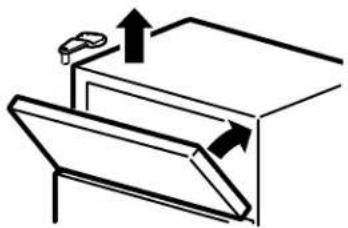
Center Hinge Pin Plastic Washer and Spacer6.2.2 Tilt the door toward the cabinet, lifting the top hinge so the pin fits into the socket on the top of the door.
natural_image
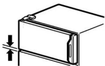
Simple line drawing of a cabinet with an upward arrow and a car on top (no text or symbols)6.2.3 Make sure the door is slightly above the top of the cabinet and the gap between the doors is even across the front. Tighten the top hinge screws. Do not overtighten these screws—tighten them until they are just snug, then turn them another one-half turn.
natural_image
Simple line drawing of a door or cabinet with an arrow indicating upward motion (no text or symbols)
Newer refrigerators sound different from older refrigerators. Modern refrigerators have more features and use newer technology.
Do you hear what I hear? These sounds are normal.
HUMMM... WHOOSH...
■ The new high efficiency compressor may run faster and longer than your old refrigerator and you may hear a high-pitched hum or pulsating sound while it is operating.
■ You may hear a whooshing sound when the doors close. This is due to pressure equalizing within the refrigerator.

■ You may hear the fans spinning at high speeds. This happens when the refrigerator is first plugged in, when the doors are opened frequently or when a large amount of food is added to the refrigerator or freezer compartments. The fans are helping to maintain the correct temperatures.
CLICKS, POPS, CRACKS and CHIRPS
■ You may hear cracking or popping sounds when the refrigerator is first plugged in. This happens as the refrigerator cools to the correct temperature.
■ The compressor may cause a clicking or chirping sound when attempting to restart (this could take up to 5 minutes).
■ Expansion and contraction of cooling coils during and after defrost can cause a cracking or popping sound.
■ On models with an icemaker, after an icemaking cycle, you may hear the ice cubes dropping into the ice bucket.
WATER SOUNDS
■ The flow of refrigerant through the freezer cooling coils may make a gurgling noise like boiling water.
■ Water dropping on the defrost heater can cause a sizzling, popping or buzzing sound during the defrost cycle.
■ A water dripping noise may occur during the defrost cycle as ice melts from the evaporator and flows into the drain pan.
■ Closing the door may cause a gurgling sound due to pressure equalization.
For additional information on normal icemaker operating sounds, see the About the automatic icemaker section.

Troubleshooting Tips
Save time and money! Review the charts on the following
pages first and you may not need to call for service.
| Problem Possible Causes What To Do | ||
| Refrigerator does not operate | Refrigerator in defrost cycle. | ·Wait about 30 minutes for defrost cycle to end. |
| Temperature control dial in 0 position. setting. | ·Move the temperature control dial to a temperature | |
| Refrigerator is unplugged. | ·Push the plug completely into the outlet. | |
| The fuse is blown/circuit breaker is tripped. | ·Replace fuse or reset the breaker. | |
| Vibration or rattling (slight vibration need adjusting. is normal) | Roller screws or leveling legs | ·See Rollers and Leveling Legs. |
| Motor operates for long periods or cycles on and off frequently. (Modern refrigerators with more storage space and a larger freezer require more operating time. They start and stop often to maintain even temperatures.) | Normal when refrigerator is first plugged in. | ·Wait 24 hours for the refrigerator to completely cool down. |
| Often occurs when large amounts of food are placed in refrigerator. | ·This is normal. | |
| Door left open. | ·Check to see if package is holding door open. | |
| Hot weather or frequent door openings. | ·This is normal. | |
| Temperature control dial set at the coldest setting. | ·See About the temperature control dial. | |
| Grille and condenser need cleaning. | ·See Care and cleaning. | |
| Fresh food or freezer compartment too warm | Temperature control dial not set cold enough. | ·See About the temperature control dial. |
| Warm weather or frequent door openings. | ·Set the temperature control dial one step colder. See About the temperature control dial. | |
| Door left open. | ·Check to see if package is holding door open. | |
| Package blocking air duct in freezer compartment. | ·Check to see if package is blocking air duct in freezer compartment. | |
| Frost or ice crystals on frozen food (frost within package is normal) | Door left open. | ·Check to see if package is holding door open. |
| Too frequent or too long door openings. | ||

Troubleshooting Tips
| Problem Possible Causes What To Do | ||
| Automatic icemaker does not work (on some models) | Icemaker power switch is not on. | • On power switch models, set the power switch to the 1(on) position. On feeler arm models, move the feeler arm to the ON (down) position. |
| Water supply turned off or not connected. | • See Installing the water line. | |
| Freezer compartment too warm. cool down. | • Wait 24 hours for the refrigerator to completely | |
| Piled up cubes in the storage bin cause the icemaker to shut off. | • Level cubes by hand. | |
| Frequent “buzzing” sound | Icemaker is on but the water supply to the refrigerator has not been connected. | • Turn the icemaker off. On power switch models, set the power switch to the 0 (off) position. On feeler arm models, move the feeler arm to the STOP (up) position. Keeping it on will damage the water valve. |
| Cubes too small | Water shutoff valve connecting refrigerator to water line may be clogged. | • Call the plumber to clear the valve. |
| Slow ice cube freezing | Door left open. | • Check to see if package is holding door open. |
| Temperature control dial not set cold enough. | • See About the temperature control dial. | |
| Ice cubes have odor/taste | Ice storage bin needs cleaning. | • Empty and wash bin. Discard old cubes. |
| Food transmitting odor/taste to ice cubes. | • Wrap foods well. | |
| Interior of refrigerator needs cleaning. | • See Care and cleaning. | |
| Moisture forms on cabinet surface between the doors | Not unusual during periods of high humidity. | • Wipe surface dry and reset temperature control dial one setting colder. |
| Moisture collects inside (in humid weather, air carries moisture into refrigerator when doors are opened) | Too frequent or too long door openings. | |
| Refrigerator has odor | Foods transmitting odor to refrigerator. | • Foods with strong odors should be tightly wrapped. • Keep an open box of baking soda in the refrigerator; replace every three months. |
| Interior needs cleaning. | • See Care and cleaning. | |
natural_image
Pure mechanical diagram showing a bracket and guide rails without any text or symbolsnatural_image
Simple line drawing of a metal grate with a black arrow pointing to the center (no text or symbols)natural_image
Illustration of hands holding a metal grater with an upward arrow indicating motion (no text or symbols)natural_image
Illustration of a hand holding a wire cage with arrows indicating rotation (no text or symbols)text_image
Diagram showing a mechanical or electrical component with labeled parts and directional arrows indicating movement or force.Estante de escalón
natural_image
Technical line drawing of a staircase with stairs and windows (no text or symbols)natural_image
Line drawing of a hand inserting a component into a storage unit (no text or symbols)natural_image
Two line drawings showing a hand holding a small object above and a small object on a flat surface below (no text or symbols)natural_image
Illustration of two rectangular containers with textured surfaces, no visible text or symbolsnatural_image
Technical line drawing of a mechanical housing or enclosure with mounting bracket (no text or symbols)Gaveta de servicio
natural_image
Simple line drawing of a hand placing a paper into a container (no text or symbols)natural_image
Diagram of a vehicle chassis inside a vehicle chassis frame, showing structural components without any text or labels.natural_image
Line drawing of a hand using a tool to press or write on a document inside a container (no text or symbols visible)natural_image
Illustration of a hand using a tool to adjust or install a component on a shelf (no text or symbols visible)natural_image
Illustration of a hand holding a card with a partially visible card (no text or symbols)Modelos 15, 16, 17, 18
ANTES DE INICIAR
natural_image
Pure mechanical diagram showing a lever and base assembly without any text, numbers, or symbols1 CÓMO INSTALAR LA LÍNEA DEL AGUA
ANTES DE INICIAR
natural_image
Simple line drawing of a straight rod or rod with no text or symbolsnatural_image
Technical line drawing of two mechanical components (no text or symbols)natural_image
Simple line drawing of a curved pipe or tube with an arrow pointing to it (no text or symbols)3 PERFORE EL ORIFICIO PARA LA VÁLVULA
natural_image
Simple line drawing of a mechanical component with a threaded end and curved top (no text or symbols)natural_image
Simple line drawing of a flower with a curved arrow above it, no text or symbols present.⑨ CONECTE LA TUBERÍA AL REFRIGERADOR
NOTAS:
natural_image
Pure technical line drawing of a rectangular frame with mounting holes and internal ribs (no text or symbols)natural_image
Mechanical component diagram showing a bolt and housing with an upward arrow (no text or symbols)natural_image
Pure technical diagram of a rectangular structural component with internal forces and supports (no text or symbols)natural_image
Mechanical clamp mechanism diagram showing rotational motion (no text or symbols)11 CONECTE EL REFRIGERADOR
natural_image
Illustration of a hand inserting a plug into an electrical outlet with three socket covers (no text or symbols)12 INICIE LA MÁQUINA DE HIELO
text_image
Interruptornatural_image
Illustration of a hand inserting a plug into an electrical outlet (no text or symbols)natural_image
Line drawing of an open refrigerator with multiple doors and shelves (no text or symbols)natural_image
Pure technical line drawing of a mechanical component with no text or symbolsnatural_image
Technical line drawing of a mechanical assembly with no visible text or symbolsnatural_image
Simple line drawing of a box with an open lid and an arrow indicating direction (no text or symbols)natural_image
Simple line drawing of two stacked rectangular blocks on a base (no text or symbols)natural_image
Simple line drawing of a cabinet with an arrow indicating rotation (no text or symbols)3 RETIRE LA PUERTA DE LOS ALIMENTOS FRESCOS
natural_image
Simple line drawing of a rectangular frame with vertical connectors (no text or symbols)natural_image
Technical line drawing showing two mechanical assembly configurations (no text or symbols)natural_image
Simple line drawing of a cabinet or cabinet with an open lid and handle (no text or symbols)natural_image
Simple line drawing of a rectangular frame with a flat top and bottom, no text or symbols present.natural_image
Simple line drawing of a container with horizontal shelves and an arrow indicating rotation (no text or symbols)natural_image
Simple line drawing of a container with an arrow indicating direction (no text or symbols)natural_image
Simple line drawing of a mechanical joint or bracket with a bolt and a circle (no text or symbols)4 CÓMO INVERTIR LOS ACCESORIOS
natural_image
Simple line drawing of a structural bracket with two vertical supports and a horizontal base (no text or symbols)natural_image
Pure mechanical assembly diagram showing a bracket with mounting holes and dashed alignment lines (no text or symbols)natural_image
Pure mechanical assembly diagram showing mounting brackets and fasteners (no text or symbols)natural_image
Technical line drawing of a door panel with a tap symbol inset (no text or labels)natural_image
Simple line drawing of a rectangular object with a vertical rod and protruding pins (no text or symbols)natural_image
Simple line drawing of a rectangular object with a small protrusion and a small arrow pointing to its side (no text or symbols)natural_image
Simple line drawing of a rectangular object with a side protrusion and vertical alignment lines (no text or symbols)5.4.2 Retire la manija.

natural_image
Simple line drawing of a rectangular object with a small protrusion and vertical dimension lines (no text or symbols)6 CÓMO VOLVER A COLGAR LAS PUERTAS
natural_image
Simple 3D diagram of a rectangular block with an arrow indicating rotation or movement (no text or symbols)natural_image
Mechanical assembly diagram showing a bolt and connecting rod (no text or labels)natural_image
Simple line drawing of a mechanical clamp or bracket assembly (no text or symbols)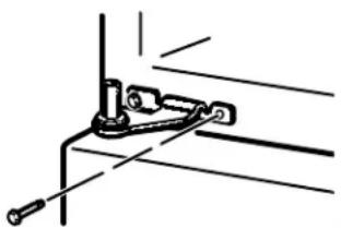
natural_image
Pure mechanical linkage diagram without any text, numbers, or symbolsnatural_image
Simple line drawing of a cabinet with an elevator and directional arrows indicating motion (no text or symbols)natural_image
Diagram of a door or cabinet with an arrow indicating upward motion (no text or symbols present)