EM1399-LD - Barcode Reader Newland - Free user manual and instructions
Find the device manual for free EM1399-LD Newland in PDF.

User questions about EM1399-LD Newland
0 question about this device. Answer the ones you know or ask your own.
Ask a new question about this device
Download the instructions for your Barcode Reader in PDF format for free! Find your manual EM1399-LD - Newland and take your electronic device back in hand. On this page are published all the documents necessary for the use of your device. EM1399-LD by Newland.
USER MANUAL EM1399-LD Newland
natural_image
Electronic circuit board with integrated circuits and a lens, shown against a green background (no text or symbols visible)Disclaimer
© 2017 Fujian Newland Auto-ID Tech. Co., Ltd. All rights reserved.
Please read through the manual carefully before using the product and operate it according to the manual. It is advised that you should keep this manual for future reference.
Do not disassemble the device or remove the seal label from the device, doing so will void the product warranty provided by Fujian Newland Auto-ID Tech. Co., Ltd.
All pictures in this manual are for reference only and actual product may differ. Regarding to the product modification and update, Fujian Newland Auto-ID Tech. Co., Ltd. reserves the right to make changes to any software or hardware to improve reliability, function, or design at any time without notice. The information contained herein is subject to change without prior notice.
The products depicted in this manual may include software copyrighted by Fujian Newland Auto-ID Tech. Co., Ltd or third party. The user, corporation or individual, shall not duplicate, in whole or in part, distribute, modify, decompile, disassemble, decode, reverse engineer, rent, transfer or sublicense such software without prior written consent from the copyright holders.
This manual is copyrighted. No part of this publication may be reproduced, distributed or used in any form without written permission from Newland.
Fujian Newland Auto-ID Tech. Co., Ltd. reserves the right to make final interpretation of the statement above.
Fujian Newland Auto-ID Tech. Co., Ltd.
3F, Building A, No.1, Rujiang West Rd., Mawei, Fuzhou, Fujian, China 350015
http://www.newlandaidc.com
Revision History
| Version | Description | Date |
| V1.0.0 | Initial release. | April 21, 2017 |
Table of Contents
Revision History....-3-
Chapter 1 Getting Started....1
Introduction....1
About This Guide....2
Connecting EVK and PC....2
Barcode Scanning....2
Configuring the EM1399-LD 2
Command Programming....2
Read Register....3
Write Register 6
Enable/Disable EEPROM Write 9
Write EEPROM....11
Read EEPROM....14
Registers....17
Barcode Programming 34
Enter/Exit Setup 34
Programming Barcode Data 34
Factory Defaults....35
Chapter 2 Scan Mode....36
Manual Mode 36
Continuous Mode....37
Sense Mode....40
Command Trigger Mode 44
Chapter 3 Notification....45
Good Read Beep 45
Decode Result Notification....46
Other Settings....47
Silent Mode 47
Illumination....47
Chapter 4 Communication Settings....48
TTL-232 Interface 49
Baud Rate 49
Parity Check....50
Stop Bit 50
Data Bit 51
USB Interface 53
USB HID-KBW 53
Standard Keyboard 54
Emulate ALT+Keypad 54
USB Country Keyboard Types....57
Inter-Keystroke Delay 60
Convert Case....61
Emulate Numeric Keypad 62
USB DataPipe 63
USB COM Port Emulation....63
HID-POS....64
Access the Engine with Your Program....65
Acquire Scanned Data 65
VID/PID 65
Chapter 5 Prefix & Suffix ...... 66
Introduction 66
Prefix Sequence....67
Custom Prefix 68
Enable/Disable Custom Prefix 68
Set Custom Prefix 68
AIM ID Prefix....69
CODE ID Prefix....70
Restore All Default Code IDs 70
Set Code ID 70
Custom Suffix 74
Enable/Disable Custom Suffix....74
Set Custom Suffix 75
Terminating Character Suffix 76
Enable/Disable Terminating Character Suffix 76
Set Terminating Character Suffix 77
Chapter 6 Symbologies ....78
Introduction 78
Global Settings 78
Enable/Disable All Symbologies 78
Video Reverse 78
Code 128 79
Restore Factory Defaults 79
Enable/Disable Code 128 79
Set Length Range for Code 128 80
UCC/EAN-128 81
Restore Factory Defaults 81
Enable/Disable UCC/EAN-128....81
Set Length Range for UCC/EAN-128 82
AIM 128 83
Restore Factory Defaults 83
Enable/Disable AIM 128....83
Set Length Range for AIM 128....84
EAN-8 85
Restore Factory Defaults 85
Enable/Disable EAN-8 85
Transmit Check Digit....85
Add-On Code 86
Add-On Code Required 87
EAN-8 Extension....87
EAN-13 88
Restore Factory Defaults 88
Enable/Disable EAN-13 88
Transmit Check Digit....88
Add-On Code 89
Add-On Code Required....90
ISSN 91
Restore Factory Defaults 91
Enable/Disable ISSN 91
ISBN 92
Restore Factory Defaults 92
Transmit Preamble Character 99
Add-On Code 100
Add-On Code Required....101
Interleaved 2 of 5 102
Restore Factory Defaults 102
Enable/Disable Interleaved 2 of 5 102
Check Digit Verification 103
Set Length Range for Interleaved 2 of 5 .... 104
ITF-6 105
Restore Factory Defaults 105
Enable/Disable ITF-6 105
ITF-14 106
Restore Factory Defaults 106
Enable/Disable ITF-14 106
Deutsche 14....107
Restore Factory Defaults 107
Enable/Disable Deutsche 14....107
Deutsche 12....108
Restore Factory Defaults 108
Enable/Disable Deutsche 12....108
Matrix 2 of 5 (European Matrix 2 of 5)....109
Restore Factory Defaults 109
Enable/Disable Matrix 2 of 5....109
Check Digit Verification 110
Set Length Range for Matrix 2 of 5....111
Industrial 25 112
Restore Factory Defaults 112
Enable/Disable Industrial 25 112
Check Digit Verification 113
Set Length Range for Industrial 25 114
Standard 25 115
Restore Factory Defaults 115
Enable/Disable Standard 25 115
Check Digit Verification....116
Set Length Range for Standard 25 ...... 117
Code 39 118
Restore Factory Defaults 118
Enable/Disable Code 39 118
Check Digit Verification 119
Transmit Start/Stop Characters.... 120
Enable/Disable Code 39 Full ASCII 120
Set Length Range for Code 39 121
Codabar 122
Restore Factory Defaults 122
Enable/Disable Codabar 122
Check Digit Verification 123
Start/Stop Characters.... 124
Set Length Range for Codabar 125
Code 93 126
Restore Factory Defaults 126
Enable/Disable Code 93 126
Check Digit Verification 127
Set Length Range for Code 93 128
Code 11 129
Restore Factory Defaults 129
Enable/Disable Code 11 129
Check Digit Verification 130
Set Length Range for Code 11 .... 131
Plessey 132
Restore Factory Defaults 132
Enable/Disable Plessey 132
Check Digit Verification 133
Set Length Range for Plessey 134
MSI-Plessey....135
Restore Factory Defaults 135
Set Length Range for MSI-Plessey....137
RSS-14 138
Restore Factory Defaults 138
Enable/Disable RSS-14 138
Transmit Application Identifier "01" 138
RSS-Limited 139
Restore Factory Defaults 139
Enable/Disable RSS-Limited 139
Transmit Application Identifier "01" 139
RSS-Expand 140
Restore Factory Defaults 140
Enable/Disable RSS-Expand 140
Appendix....141
Factory Defaults Table.... 141
AIM ID Table 148
Code ID Table....150
ASCII Table 151
Digit Barcodes 155
Save/Cancel Barcodes 158
F1\~F12 159
Chapter 1 Getting Started
Introduction
The NLS-EM1399-LD OEM scan engines (the "EM1399-LD" or the "engine"), armed with the Newland patented UME® computerized image recognition system, bring about a new era of 1D barcode scan engines.
The EM1399-LD's 1D barcode decoder chip ingeniously blends UWMG® technology and advanced chip design & manufacturing, which significantly simplifies application design and delivers superior performance and solid reliability with low power consumption.
The EM1399-LD supports EAN-13, EAN-8, UPC-A, UPC-E, ISSN, ISBN, Codabar, Code 128, Code 93, ITF-6, ITF-14, Interleaved 2 of 5, Industrial 2 of 5, Standard 2 of 5, Matrix 2 of 5, GS1 Databar, Code 39, Code 11, MSI-Plessey, Plessey.
This compact scan engine weighs only 5 grams and can easily fit into space-constrained equipment such as data collectors, meter readers, ticket validators and PDAs. Moreover, the instant power on/off feature along with ultra low power consumption brings greater efficiency and convenience in barcode scanning.
About This Guide
This guide provides programming instructions for the EM1399-LD. Users can configure the scan engine by scanning the programming barcodes included in this manual or by sending serial commands to the device.
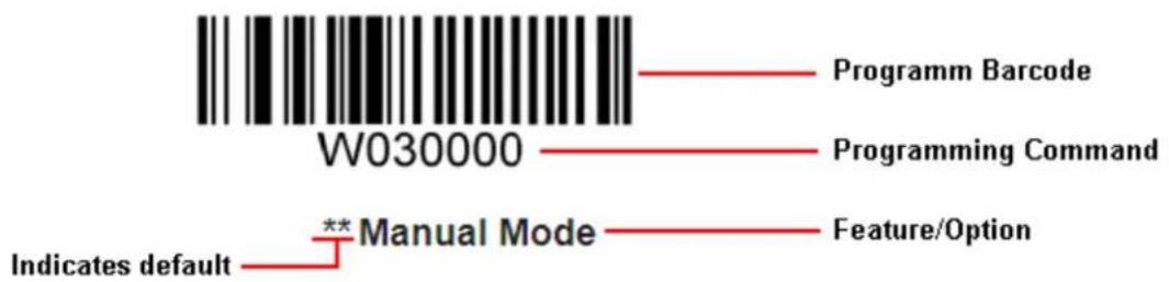
The EM1399-LD has been properly configured for most applications and can be put into use without further configuration. Users may check the Factory Defaults Table in Appendix for reference. Throughout the manual, programming barcodes marked with asterisks (**) are factory default values.
Connecting EVK and PC
The EVK tool is provided to assist users in application development for the EM1399-LD. The EM1399-LD can be connected to the EVK via a 12-pin flat flexible cable. Either USB connection or RS-232 connection can be used when connecting the EVK to PC. A driver is required if EVK wants to communicate with EM1399-LD and receive decoded data through USB COM port.
Barcode Scanning
Powered by imaging technology and Newland patented Technology, the EM1399-LD features fast scanning and accurate decoding. Barcodes rotated at any angle can still be read with ease. When scanning a barcode, simply center the aiming beam projected by the EM1399-LD over the barcode.
Configuring the EM1399-LD
There are two ways to configure the engine: barcode programming and command programming.
Command Programming
The EM1399-LD can be configured by serial commands sent from the host device. Note that communication parameters on the engine and the host must match so that two devices can communicate with each other. The default settings of the engine are 9600bps, no parity check, 8 data bits, 1 stop bit, and no flow control. The engine uses 8-bit registers.
Read Register
The read register command is used to read the contents of 1 to 256 contiguous registers in the engine.
Syntax: {Prefix1} {Types} {Lens} {Address} {Datas} {FCS}
Prefix1 : 0x7E 0x00 (2 bytes)
Types : 0x07 (1 byte)
Lens : 0x01 (1 byte).
Address: 0x0000~0xFFFF (2 bytes), starting register address.
Datas : 0x00~0xFF (1 byte), number of registers to be read. When Datas=0x00, 256 contiguous registers are to be read.
FCS : CRC-CCITT checksum (2 bytes)
Computation sequence: Types+ Lens+Address+Datas;
polynomial: X ^16 +X ^12 +X ^5 +1(0x1021), initial value: 0x0000.
The following C language program is provided for reference.
unsigned int crc_cal_by_bit(unsigned char* ptr, unsigned int len)
{
    unsigned int crc = 0;
    while(len-- != 0)
    {
    for(unsigned char i = 0x80; i != 0; i /= 2)
    {
    crc *= 2;
    if((crc&0x10000) != 0)
    crc ^= 0x11021;
    if((*ptr&i) != 0)
    crc ^= 0x1021;
    }
    ptr++;
    }
    return crc;
}
Reply: {Prefix2} {Types} {Lens} {Datas} {FCS}
1) Success message:
Prefix2 : 0x02 0x00
Types : 0x00 (success)
Lens : Byte count of Datas returned. If Lens=0x00, that means values of 256 contiguous registers are returned.
Datas : 0x00\~0xFF, data that are returned.
FCS : CRC-CCITT checksum.
2) FCS error message:
Prefix2 : 0x02 0x00
Types : 0x01 (incorrect FCS)
Lens : 0x01
Datas : 0x00
FCS : 0x04 0x01 (CRC-CCITT checksum)
3) Invalid command message (Command starting with 0x7e 0x00 is shorter than the required length or of wrong type):
Prefix2 : 0x02 0x00
Types : 0x03 (invalid command)
Lens : 0x01
Datas : 0x00
FCS : 0x6A 0x61 (CRC-CCITT checksum)
Example:
Read the contents (0x35, 0x36, 0x37) of 3 contiguous registers starting from register 0x0005.
1) Read operation succeeds:
Command sent: 0x7e 0x00 0x07 0x01 0x00 0x05 0x03 0xde 0xf6
Message received: 0x02 0x00 0x00 0x03 0x35 0x36 0x37 0x2a 0xba
2) Incorrect FCS:
Command sent: 0x7e 0x00 0x07 0x01 0x00 0x05 0x03 0x33 0x34
Message received: 0x02 0x00 0x01 0x01 0x00 0x04 0x01
3) Invalid command:
Command sent: 0x7e 0x00 0x07 0x01 0x00 0x05 0x03 0x33
Message received: 0x02 0x00 0x03 0x01 0x00 0x6A 0x61
Write Register
The write register command is used to write contiguous registers (1 to 256 registers) in the engine.
Syntax: {Prefix1} {Types} {Lens} {Address} {Datas} {FCS}
Prefix1 : 0x7E 0x00 (2 bytes)
Types : 0x08 (1 byte)
Lens : 0x00~0xFF (1 byte), byte count, i.e. number of registers written. When Lens=0x00, 256 contiguous registers are to be written.
Address : 0x0000~0xFFFF (2 bytes), starting register address.
Datas : 0x00~0xFF (1~256 bytes), data to be written into the register(s)
FCS : CRC-CCITT checksum (2 bytes).
Computation sequence: Types+ Lens+Address+Datas;
polynomial: X ^16 +X ^12 +X ^5 +1 (0x1021), initial value: 0x0000.
The following C language program is provided for reference.
unsigned int crc_cal_by_bit(unsigned char* ptr, unsigned int len)
{
    unsigned int crc = 0;
    while(len-- != 0)
    {
    for(unsigned char i = 0x80; i != 0; i /= 2)
    {
    crc *= 2;
    if((crc&0x10000) != 0)
    crc ^= 0x11021;
    if((*ptr&i) != 0)
    crc ^= 0x1021;
    }
    ptr++;
    }
    return crc;
}
Reply: {Prefix2} {Types} {Lens} {Datas} {FCS}
1) Success message:
Prefix2 : 0x02 0x00
Types : 0x00 (success)
Lens : 0x01
Datas : 0x00
FCS : 0x33 0x31 (CRC-CCITT checksum)
2) FCS error message:
Prefix2 : 0x02 0x00
Types : 0x01 (incorrect FCS)
Lens : 0x01
Datas : 0x00
FCS : 0x04 0x01 (CRC-CCITT checksum)
3) Invalid command message (Command starting with 0x7e 0x00 is shorter than the required length or of wrong type):
Prefix2 : 0x02 0x00
Types : 0x03 (invalid command)
Lens : 0x01
Datas : 0x00
FCS : 0x6A 0x61 (CRC-CCITT checksum)
Example:
Write 0x31, 0x32, 0x33, 0x34 into 4 contiguous registers starting from register 0x000a.
1) Write operation succeeds:
Command sent: 0x7e 0x00 0x08 0x04 0x00 0x26 0x31 0x32 0x33 0x34 0xcd 0xa4
Message received: 0x02 0x00 0x00 0x01 0x00 0x33 0x31
2) Incorrect FCS:
Command sent: 0x7e 0x00 0x08 0x04 0x00 0x26 0x31 0x32 0x33 0x34 0x33 0x34
Message received: 0x02 0x00 0x01 0x01 0x00 0x04 0x01
3) Invalid command:
Command sent: 0x7e 0x00 0x08 0x04 0x00 0x26 0x31 0x32 0x33 0x34 0x33
Message received: 0x02 0x00 0x03 0x01 0x00 0x6A 0x61
Enable/Disable EEPROM Write
By default, EEPROM write is disabled after the device is powered up. You need to enable it before a write operation and recommendedly disable it afterwards to prevent miswriting.
Syntax: {Prefix1} {Types} {Lens} {Address} {Datas} {FCS}
Prefix1 : 0x7E 0x00
Types : 0x03 (EEPROM write enable)/ 0x00 (EEPROM write disable)
Lens : Byte count of Datas, 0x01 recommended.
Address : No specific significance.
Datas : No specific significance.
FCS : CRC-CCITT checksum (2 bytes).
Computation sequence: Types+ Lens+Address+Datas;
polynomial: X ^16 +X ^12 +X ^5 +1 (0x1021), initial value: 0x0000.
The following C language program is provided for reference.
unsigned int crc_cal_by_bit(unsigned char* ptr, unsigned int len)
{
    unsigned int crc = 0;
    while(len-- != 0)
    {
    for(unsigned char i = 0x80; i != 0; i /= 2)
    {
    crc *= 2;
    if((crc&0x10000) != 0)
    crc ^= 0x11021;
    if((*ptr&i) != 0)
    crc ^= 0x1021;
    }
    ptr++;
    }
    return crc;
}
Reply: {Prefix2} {Types} {Lens} {Datas} {FCS}
1) Success message:
Prefix2 : 0x02 0x00
Types : 0x00 (success)
Lens : 0x01
Datas : 0x00
FCS : 0x33 0x31 (CRC-CCITT checksum)
2) FCS error message:
Prefix2 : 0x02 0x00
Types : 0x01 (incorrect FCS)
Lens : 0x01
Datas : 0x00
FCS : 0x04 0x01 (CRC-CCITT checksum)
3) Invalid command message (Command starting with 0x7e 0x00 is shorter than the required length or of wrong type):
Prefix2 : 0x02 0x00
Types : 0x03 (invalid command)
Lens : 0x01
Datas : 0x00
FCS : 0x6A 0x61 (CRC-CCITT checksum)
Write EEPROM
The engine has 512 bytes of EEPROM. The EEPROM write command is used to write data to up to 256 addresses. You need to enable EEPROM write before a write operation and recommendedly disable it afterwards to prevent miswriting. Note that writing without enabling it first will not return any error message. So it is recommended to implement EEPROM read operation after every write for verification.
Syntax: {Prefix1} {Types} {Lens} {Address} {Datas} {FCS}
Prefix1 : 0x7E 0x00
Types : 0x04
Lens : 0x00~0xFF, byte count of Datas. When Lens=0x00, 256 bytes are to be written.
Address : 0x0000~0xFFFF, starting address to write data to.
Datas : 0x00~0xFF, data to be written into the EEPROM
FCS : CRC-CCITT checksum (2 bytes).
Computation sequence: Types+ Lens+Address+Datas;
polynomial: X ^16 +X ^12 +X ^5 +1 (0x1021), initial value: 0x0000.
The following C language program is provided for reference.
unsigned int crc_cal_by_bit(unsigned char* ptr, unsigned int len)
{
    unsigned int crc = 0;
    while(len-- != 0)
    {
    for(unsigned char i = 0x80; i != 0; i /= 2)
    {
    crc *= 2;
    if((crc&0x10000) != 0)
    crc ^= 0x11021;
    if((*ptr&i) != 0)
    crc ^= 0x1021;
    }
    ptr++;
    }
    return crc;
}
Reply: {Prefix2} {Types} {Lens} {Datas} {FCS}
1) Success message:
Prefix2 : 0x02 0x00
Types : 0x00 (success)
Lens : 0x01
Datas : 0x00
FCS : 0x33 0x31 (CRC-CCITT checksum)
2) FCS error message:
Prefix2 : 0x02 0x00
Types : 0x01 (incorrect FCS)
Lens : 0x01
Datas : 0x00
FCS : 0x04 0x01 (CRC-CCITT checksum)
3) EERPOM not responding message:
Prefix2 : 0x02 0x00
Types : 0x02 (EEPROM not responding)
Lens : 0x01
Datas : 0x00
FCS : 0x5d 0x51 (CRC-CCITT checksum)
4) Invalid command message (Command starting with 0x7e 0x00 is shorter than the required length or of wrong type):
Prefix2 : 0x02 0x00
Types : 0x03 (invalid command)
Lens : 0x01
Datas : 0x00
FCS : 0x6A 0x61 (CRC-CCITT checksum)
Example:
Write 0x51, 0x52, 0x53, 0x54 into 4 contiguous addresses starting from address 0x0000.
1) Write operation succeeds:
Command sent: 0x7e 0x00 0x04 0x04 0x00 0x00 0x51 0x52 0x53 0x54 0xbc 0x17
Message received: 0x02 0x00 0x00 0x01 0x00 0x33 0x31
2) Incorrect FCS:
Command sent: 0x7e 0x00 0x04 0x03 0x00 0x00 0x51 0x52 0x53 0x54 0x33 0x34
Message received: 0x02 0x00 0x01 0x01 0x00 0x04 0x01
Read EEPROM
The engine has 512 bytes of EEPROM. The EEPROM read command is used to read the contents from 1 to 256 contiguous addresses of the EEPROM.
Syntax: {Prefix1} {Types} {Lens} {Address} {Datas} {FCS}
Prefix1 : 0x7E 0x00
Types : 0x05
Lens : 0x01
Address: 0x0000~0xFFFF (2 bytes), starting EEPROM address to read.
Datas : 0x00~0xFF, number of EEPROM addresses to be read. When Datas=0x00, 256 contiguous addresses are to be read.
FCS : C R C -CCITT checksum (2 bytes)
Computation sequence: Types+ Lens+Address+Datas;
polynomial: X ^16 +X ^12 +X ^5 +1(0x1021), initial value: 0x0000.
The following C language program is provided for reference.
unsigned int crc_cal_by_bit(unsigned char* ptr, unsigned int len)
{
    unsigned int crc = 0;
    while(len-- != 0)
    {
    for(unsigned char i = 0x80; i != 0; i /= 2)
    {
    crc *= 2;
    if((crc&0x10000) != 0)
    crc ^= 0x11021;
    if((*ptr&i) != 0)
    crc ^= 0x1021;
    }
    ptr++;
    }
    return crc;
}
Reply: {Prefix2} {Types} {Lens} {Datas} {FCS}
1) Success message:
Prefix2 : 0x02 0x00
Types : 0x00 (success)
Lens : Byte count of Datas returned.
Datas : 0x00\~0xFF, data that are returned.
FCS : CRC-CCITT checksum.
2) FCS error message:
Prefix2 : 0x02 0x00
Types : 0x01 (incorrect FCS)
Lens : 0x01
Datas : 0x00
FCS : 0x04 0x01 (CRC-CCITT checksum)
3) EERPOM not responding message:
Prefix2 : 0x02 0x00
Types : 0x02 (EEPROM not responding)
Lens : 0x01
Datas : 0x00
FCS : 0x5d 0x51 (CRC-CCITT checksum)
4) Invalid command message (Command starting with 0x7e 0x00 is shorter than the required length or of wrong type):
Prefix2 : 0x02 0x00
Types : 0x03 (invalid command)
Lens : 0x01
Datas : 0x00
FCS : 0x6A 0x61 (CRC-CCITT checksum)
Example:
Read the contents (0x35 0x36 0x37) of 3 contiguous EEPROM addresses starting from address 0x0005.
1) Read operation succeeds:
Command sent: 0x7e 0x00 0x05 0x01 0x00 0x05 0x03 0x9a 0x75
Message received: 0x02 0x00 0x00 0x03 0x35 0x36 0x37 0x2a 0xba
2) Incorrect FCS:
Command sent: 0x7e 0x00 0x05 0x01 0x00 0x05 0x03 0x33 0x34
Message received: 0x02 0x00 0x01 0x01 0x00 0x04 0x01
Registers
| Register | 0x0000 | |||
| Bit | Feature | |||
| Bit 7 | Reserved | |||
| Bit 6 | 1: Silent Mode Off 0: Silent Mode On | |||
| Bit 5-4 | Reserved | |||
| Bit 3-2 | Illumination:00: Off 01: On When Scanning 10/11: Always On | |||
| Bit 1-0 | Scan Mode:00: Manual Mode 01: Command Trigger Mode 10: Continuous Mode 11: Sense Mode | |||
| Register | 0x0003 | |||
| Bit | Feature | |||
| Bit 7-0 | Sensitivity0x00~0xFF: 0-255 levels. The smaller the value, the higher the sensitivity. | |||
| Register | 0x0004 | |||
| Bit | Feature | |||
| Bit 7-0 | Image Stabilization Timeout0x00-0xFF: 0.0-25.5s | |||
| Register | 0x0005 | |||
| Bit | Feature | |||
| Bit 7-0 | Timeout between Decodes0x00-0xFF: 0.0-25.5s | |||
| Register | 0x0006 | |||
| Bit | Feature | |||
| Bit 7-0 | Decode Session Timeout0x00: Infinite time; 0x01-0xFF: 1-255s | |||
| Register | 0x0007 | |||
| Bit | Feature | |||
| Bit 7-0 | Timeout between Decodes (Same Barcode)0x00: Infinite time; 0x01-0xFF: 0.1-25.5s | |||
| Register | 0x0009 | |||
| Bit | Feature | |||
| Bit 7-5 | Reserved | |||
| Bit 4 | 0: Serial Communication | |||
| Bit 3-2 | Reserved | |||
| Bit 1-0 | 00: USB DataPipe 01: USB HID-KBW 10: USB COM Port Emulation 11: USB HID-POS | |||
| Register | 0x000A | |||
| Bit | Feature | |||
| Bit 7-5 | Reserved | |||
| Bit 4 | 0: Allow Rereading Same Barcode 1: Disallow Rereading Same Barcode | |||
| Bit 3-2 | Reserved | |||
| Bit 1-0 | Security Level00-03: 0-3 level. The higher the value, the lower the error rate and efficiency. | |||
| Register | 0x000D | |||
| Bit | Feature | |||
| Bit 7-2 | Reserved | |||
| Bit 1 | 0: Video Reverse OFF 1: Video Reverse ON | |||
| Bit 0 | Reserved | |||
| Register | 0x000F | |||
| Bit | Feature | |||
| Bit 7-3 | Reserved | |||
| Bit 2-1 | 00: Do Not Transmit Programming Barcode Data 11: Transmit Programming Barcode Data | |||
| Bit 0 | 0: Exit Setup 1: Enter Setup | |||
| Register | 0x0010 | |||
| Bit | Feature | |||
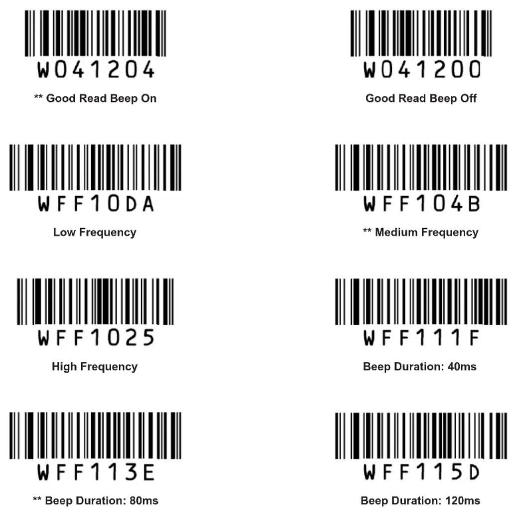
| Bit 7-0 | Good Read Beep Frequency0xDA: Low 0x4B: Medium 0x25: High | |||
| Register | 0x0011 | |||
| Bit | Feature | |||
| Bit 7-0 | Good Read Beep Duration0x1F: 40ms 0x3E: 80ms 0x5D: 120ms | |||
| Register | 0x0012 | |||
| Bit | Feature | |||
| Bit 7-3 | Reserved | |||
| Bit 2 | 1: Good Read Beep On 0: Good Read Beep Off | |||
| Bit 1-0 | Reserved | |||
| Register | 0x0019 | |||
| Bit | Feature | |||
| Bit 7-0 | USB Country Keyboard Types | |||
| 00: U.S. | 01: Belgium | 02: Brazil | ||
| 03: Canada | 04: Czech | 05: Denmark | ||
| 06: Finland | 07: France | 08: Austria | ||
| 09: Greece | 0A: Hungary | 0B: Israel | ||
| 0C: Italy | 0D: Latin America | 0E: Netherland | ||
| 0F: Norway | 10: Poland | 11: Portugal | ||
| 12: Romania | 13: Russia | 15: Slovakia | ||
| 16: Spain | 17: Sweden | 18: Switzerland | ||
| 19: Turkey1 | 1A: Turkey2 | 1B: UK | ||
| 1C: Japan | ||||
| Register | 0x001A | |||
| Bit | Feature | |||
| Bit 7-6 | Inter-keystroke delay | |||
| 00: No delay | 01: Short delay (5ms) | |||
| 10: Medium delay (10ms) | 11: Long delay (15ms) | |||
| Bit 5-3 | Convert case | |||
| 000: No Case Conversion | 001: Invert Upper and Lower Case Characters | |||
| 100/101: Convert All to Upper Case | 1 1 0/111: Convert All to Lower Case | |||
| Bit 2 | 1: Emulate Numeric Keypad | 0: Do Not Emulate Numeric Keypad | ||
| Bit 1-0 | 00: Standard Keyboard | 01: Function Key Mapping | 10/11: Emulate ALT+Keypad | |
| Register | 0x0029 | |||
| Bit | Feature | |||
| Bit 7-4 | Reserved | |||
| Bit 3 | 1: 8 Data Bits | 0: 7 Data Bits | ||
| Bit 2-1 | Parity Check00/01: None | 10: Odd | 11: Even | |
| Bit 0 | 1: 2 Stop Bits | 0: 1 Stop Bit | ||
| Register | 0x002B, 0x2A | |||
| Bit | Feature | |||
| Bit 15-13 | Reserved | |||
| Bit 12-0 | 0x09C4: Baud Rate 12000x04E2: Baud Rate 24000x0271: Baud Rate 48000x0139: Baud Rate 96000x00D0: Baud Rate 144000x009C: Baud Rate 192000x004E: Baud Rate 384000x0034: Baud Rate 576000x001A: Baud Rate 115200 | |||
| Register | 0x0031 | |||
| Bit | Feature | |||
| Bit 7-6 | Reserved | |||
| Bit 5 | 1: Enable Decode Result Notification | 0: Disable Decode Result Notification | ||
| Bit 4 | 1: Enable Terminating Character Suffix | 0: Disable Terminating Character Suffix | ||
| Bit 3 | 1: Enable Custom Suffix | 0: Disable Custom Suffix | ||
| Bit 2 | 1: Enable Custom Prefix | 0: Disable Custom Prefix | ||
| Bit 1 | 1: Enable CODE ID Prefix | 0: Disable CODE ID Prefix | ||
| Bit 0 | Prefix Sequence1: Custom+Code ID+ AIM ID | 0: Code ID+Custom+AIM ID | ||
| Register | 0x0037-0x33 | |||
| Bit | Feature | |||
| Bit 39-0 | Set Custom Prefix | |||
| Register | 0x0042-0x3E | |||
| Bit | Feature | |||
| Bit 39-0 | Set Custom Suffix | |||
| Register | 0x004D-0x49 | |||
| Bit | Feature | |||
| Bit 39-0 | Set Terminating Character Suffix | |||
| Register | 0x0061 | |||
| Bit | Feature | |||
| Bit 7-1 | Reserved | |||
| Bit 0 | 1: Enable Code 128 0: Disable Code 128 | |||
| Register | 0x0062 | |||
| Bit | Feature | |||
| Bit 7-2 | Reserved | |||
| Bit 1-0 | 00: Disable UCC/EAN 128 01: Decode as Code 128 10/11: Enable UCC/EAN 128 | |||
| Register | 0x0063 | |||
| Bit | Feature | |||
| Bit 7-2 | Reserved | |||
| Bit 1-0 | 00: Disable AIM 128 01: Decode as Code 128 10/11: Enable AIM 128 | |||
| Register | 0x0065 | |||
| Bit | Feature | |||
| Bit 7-6 | EAN-8 Extension00: Disable EAN-8 Zero Extend 01: Enable EAN-8 Zero Extend10/11: Convert EAN-8 to EAN-13 | |||
| Bit 5 | 1: Enable EAN-8 5-digit Add-on Code 0: Disable EAN-8 5-digit Add-on Code | |||
| Bit 4 | 1: Enable EAN-8 2-digit Add-on Code 0: Disable EAN-8 2-digit Add-on Code | |||
| Bit 3 | 1: EAN-8 Add-on Code Required 0: EAN-8 Add-on Code Not Required | |||
| Bit 2 | 1: Transmit EAN-8 Check Digit 0: Do Not Transmit EAN-8 Check Digit | |||
| Bit 1 | Reserved | |||
| Bit 0 | 1: Enable EAN-8 0: Disable EAN-8 | |||
| Register | 0x0066 | |||
| Bit | Feature | |||
| Bit 7-6 | Reserved | |||
| Bit 5 | 1: Enable EAN-13 5-digit Add-on Code | 0: Disable EAN-13 5-digit Add-on Code | ||
| Bit 4 | 1: Enable EAN-13 2-digit Add-on Code | 0: Disable EAN-13 2-digit Add-on Code | ||
| Bit 3 | 1: EAN-13 Add-on Code Required | 0: EAN-13 Add-on Code Not Required | ||
| Bit 2 | 1: Transmit EAN-13 Check Digit | 0: Do Not Transmit EAN-13 Check Digit | ||
| Bit 1 | Reserved | |||
| Bit 0 | 1: Enable EAN-13 | 0: Disable EAN-13 | ||
| Register | 0x0067 | |||
| Bit | Feature | |||
| Bit 7-2 | Reserved | |||
| Bit 1-0 | 00: Disable ISSN 01: Decode as EAN-13 10/11: Enable ISSN | |||
| Register | 0x0068 | |||
| Bit | Feature | |||
| Bit 7-3 | Reserved | |||
| Bit 2 | ISBN Format1: ISBN-10 0: ISBN-13 | |||
| Bit 1-0 | 00: Disable ISBN 01: Decode as EAN-13 10/11: Enable ISBN | |||
| Register | 0x0069 | |||
| Bit | Feature | |||
| Bit 7-6 | UPC-E Extension00: Disable UPC-E extend 01: Enable UPC-E extend10/11: Convert UPC-E to UPC-A | |||
| Bit 5 | 1: Enable UPC-E 5-digit Add-on Code | 0: Disable UPC-E 5-digit Add-on Code | ||
| Bit 4 | 1: Enable UPC-E 2-digit Add-on Code | 0: Disable UPC-E 2-digit Add-on Code | ||
| Bit 3 | 1: UPC-E Add-on Code Required | 0: UPC-E Add-on Code Not Required | ||
| Bit 2 | 1: Transmit UPC-E Check Digit | 0: Do Not Transmit UPC-E Check Digit | ||
| Bit 1 | Reserved | |||
| Bit 0 | 1: Enable UPC-E | 0: Disable UPC-E | ||
| Register | 0x006A | |||
| Bit | Feature | |||
| Bit 7-6 | Reserved | |||
| Bit 5-4 | UPC-E System Character01: Do not transmit system character 10/11: Transmit system character | |||
| Bit 3-2 | Reserved | |||
| Bit 1-0 | UPC-A Preamble Character00: No Preamble 01: System Character 10/11: System Character & Country Code | |||
| Register | 0x006B | |||
| Bit | Feature | |||
| Bit 7 | Reserved | |||
| Bit 6 | 1: Enable UPC-A 5-digit Add-on Code 0: Disable UPC-A 5-digit Add-on Code | |||
| Bit 5 | 1: Enable UPC-A 2-digit Add-on Code 0: Disable UPC-A 2-digit Add-on Code | |||
| Bit 4 | 1: UPC-A Add-on Code Required 0: UPC-A Add-on Code Not Required | |||
| Bit 3 | 1: Transmit UPC-A Check Digit 0: Do Not Transmit UPC-A Check Digit | |||
| Bit 2 | Reserved | |||
| Bit 1-0 | 00: Disable UPC-A 01: Decode as EAN-13 10/11: Enable UPC-A | |||
| Register | 0x006C | |||
| Bit | Feature | |||
| Bit 7-4 | Reserved | |||
| Bit 3 | 1: Transmit Interleaved 2 of 5 Check Digit 0: Do Not Transmit Interleaved 2 of 5 Check Digit | |||
| Bit 2 | 1: Enable Interleaved 2 of 5 Check Digit 0: Disable Interleaved 2 of 5 Check Digit | |||
| Bit 1 | Reserved | |||
| Bit 0 | 1: Enable Interleaved 2 of 5 0: Disable Interleaved 2 of 5 | |||
| Register | 0x006D | |||
| Bit | Feature | |||
| Bit 7-4 | Reserved | |||
| Bit 3 | 1: Transmit ITF-6 Check Digit 0: Do Not Transmit ITF-6 Check Digit | |||
| Bit 2 | Reserved | |||
| Bit 1-0 | 00: Disable ITF-6 01: Decode as Interleaved 2 of 5 10/11: Enable ITF-6 | |||
| Register | 0x006E | |||
| Bit | Feature | |||
| Bit 7-4 | Reserved | |||
| Bit 3 | 1: Transmit ITF-14 Check Digit | 0: Do Not Transmit ITF-14 Check Digit | ||
| Bit 2 | Reserved | |||
| Bit 1-0 | 00: Disable ITF-14 01: Decode as Interleaved 2 of 5 10/11: Enable ITF-14 | |||
| Register | 0x006F | |||
| Bit | Feature | |||
| Bit 7-4 | Reserved | |||
| Bit 3 | 1: Transmit Deutsche 14 Check Digit | 0: Do Not Transmit Deutsche 14 Check Digit | ||
| Bit 2 | Reserved | |||
| Bit 1-0 | 00: Disable Deutsche 14 01: Decode as Interleaved 2 of 5 10/11: Enable Deutsche 14 | |||
| Register | 0x0070 | |||
| Bit | Feature | |||
| Bit 7-4 | Reserved | |||
| Bit 3 | 1: Transmit Deutsche 12 Check Digit | 0: Do Not Transmit Deutsche 12 Check Digit | ||
| Bit 2 | Reserved | |||
| Bit 1-0 | 00: Disable Deutsche 12 01: Decode as Interleaved 2 of 5 10/11: Enable Deutsche 12 | |||
| Register | 0x0071 | |||
| Bit | Feature | |||
| Bit 7-4 | Reserved | |||
| Bit 3 | 1: Transmit Matrix 2 of 5 Check Digit | 0: Do Not Transmit Matrix 2 of 5 Check Digit | ||
| Bit 2 | 1: Enable Matrix 2 of 5 Check Digit | 0: Disable Matrix 2 of 5 Check Digit | ||
| Bit 1 | Reserved | |||
| Bit 0 | 1: Enable Matrix 2 of 5 | 0: Disable Matrix 2 of 5 | ||
| Register | 0x0072 | |||
| Bit | Feature | |||
| Bit 7-4 | Reserved | |||
| Bit 3 | 1: Transmit Industrial 25 Check Digit | 0: Do Not Transmit Industrial 25 Check Digit | ||
| Bit 2 | 1: Enable Industrial 25 Check Digit | 0: Disable Industrial 25 Check Digit | ||
| Bit 1 | Reserved | |||
| Bit 0 | 1: Enable Industrial 25 | 0: Disable Industrial 25 | ||
| Register | 0x0073 | |||
| Bit | Feature | |||
| Bit 7-4 | Reserved | |||
| Bit 3 | 1: Transmit Standard 25 Check Digit | 0: Do Not Transmit Standard 25 Check Digit | ||
| Bit 2 | 1: Enable Standard 25 Check Digit | 0: Disable Standard 25 Check Digit | ||
| Bit 1 | Reserved | |||
| Bit 0 | 1: Enable Standard 25 | 0: Disable Standard 25 | ||
| Register | 0x0074 | |||
| Bit | Feature | |||
| Bit 7-6 | Reserved | |||
| Bit 5 | 1: Enable Code 39 Full ASCII | 0: Disable Code 39 Full ASCII | ||
| Bit 4 | 1: Transmit Code 39 Check Digit | 0: Do Not Transmit Code 39 Check Digit | ||
| Bit 3 | 1: Enable Code 39 Check Digit | 0: Disable Code 39 Check Digit | ||
| Bit 2 | 1: Transmit Code 39 Start/Stop Characters0: Do Not Transmit Code 39 Start/Stop Characters | |||
| Bit 1 | Reserved | |||
| Bit 0 | 1: Enable Code 39 | 0: Disable Code 39 | ||
| Register | 0x0075 | |||
| Bit | Feature | |||
| Bit 7 | Reserved | |||
| Bit 6 | 1: Transmit Codabar Check Digit | 0: Do Not Transmit Codabar Check Digit | ||
| Bit 5 | 1: Enable Codabar Check Digit | 0: Disable Codabar Check Digit | ||
| Bit 4-3 | Codabar Start/Stop Character Format:00: ABCD/ABCD10: abcd/abcd | 01: ABCD/TN*E11: abcd/tn*e | ||
| Bit 2 | 1: Transmit Codabar Start/Stop Characters0: Do Not Transmit Codabar Start/Stop Characters | |||
| Bit 1 | Reserved | |||
| Bit 0 | 1: Enable Codabar | 0: Disable Codabar | ||
| Register | 0x0076 | |||
| Bit | Feature | |||
| Bit 7-4 | Reserved | |||
| Bit 3 | 1: Transmit Code 93 Check Digit | 0: Do Not Transmit Code 93 Check Digit | ||
| Bit 2 | 1: Enable Code 93 Check Digit | 0: Disable Code 93 Check Digit | ||
| Bit 1 | Reserved | |||
| Bit 0 | 1: Enable Code 93 | 0: Disable Code 93 | ||
| Register | 0x0077 | |||
| Bit | Feature | |||
| Bit 7-6 | Reserved | |||
| Bit 5 | 1: Transmit Code 11 Check Digit | 0: Do Not Transmit Code 11 Check Digit | ||
| Bit 4-2 | Code 11 Check Digit Verification:000: Disable001: One Check Digit, MOD11010: Two Check Digits, MOD11/MOD11011: Two Check Digits, MOD11/MOD9100: One Check Digit, MOD11 (Len <= 11); Two Check Digits, MOD11/MOD11 (Len > 11)101: One Check Digit, MOD11 (Len <= 11); Two Check Digits, MOD11/MOD9 (Len > 11) | |||
| Bit 1 | Reserved | |||
| Bit 0 | 1: Enable Code 11 | 0: Disable Code 11 | ||
| Register | 0x0078 | |||
| Bit | Feature | |||
| Bit 7-4 | Reserved | |||
| Bit 3 | 1: Transmit Plessey Check Digit | 0: Do Not Transmit Plessey Check Digit | ||
| Bit 2 | 1: Enable Plessey Check Digit | 0: Disable Plessey Check Digit | ||
| Bit 1 | Reserved | |||
| Bit 0 | 1: Enable Plessey | 0: Disable Plessey | ||
| Register | 0x0079 | |||
| Bit | Feature | |||
| Bit 7-5 | Reserved | |||
| Bit 4 | 1: Transmit MSI-Plessey Check Digit 0: Do Not Transmit MSI-Plessey Check Digit | |||
| Bit 3-2 | MSI-Plessey Check Digit Verification:00: Disable01: One Check Digit, MOD1010: Two Check Digits, MOD10/MOD1011: Two Check Digits, MOD10/MOD11 | |||
| Bit 1 | Reserved | |||
| Bit 0 | 1: Enable MSI-Plessey 0: Disable MSI-Plessey | |||
| Register | 0x007A | |||
| Bit | Feature | |||
| Bit 7-3 | Reserved | |||
| Bit 2 | 1: Transmit RSS-14 Application Identifier 0: Do Not Transmit RSS-14 Application Identifier | |||
| Bit 1 | Reserved | |||
| Bit 0 | 1: Enable RSS-14 0: Disable RSS-14 | |||
| Register | 0x007B | |||
| Bit | Feature | |||
| Bit 7-3 | Reserved | |||
| Bit 2 | 1: Transmit RSS-Limited Application Identifier0: Do Not Transmit RSS-Limited Application Identifier | |||
| Bit 1 | Reserved | |||
| Bit 0 | 1: Enable RSS-Limited 0: Disable RSS-Limited | |||
| Register | 0x007C | |||
| Bit | Feature | |||
| Bit 7-1 | Reserved | |||
| Bit 0 | 1: Enable RSS-Expand 0: Disable RSS-Expand | |||
| Register | 0x0080 | |||
| Bit | Feature | |||
| Bit 7-0 | Set Code 128 Maximum Length | |||
| Register | 0x0081 | |||
| Bit | Feature | |||
| Bit 7-0 | Set Code 128 Minimum Length | |||
| Register | 0x0082 | |||
| Bit | Feature | |||
| Bit 7-0 | Set UCC/EAN-128 Maximum Length | |||
| Register | 0x0083 | |||
| Bit | Feature | |||
| Bit 7-0 | Set UCC/EAN-128 Minimum Length | |||
| Register | 0x0084 | |||
| Bit | Feature | |||
| Bit 7-0 | Set AIM 128 Maximum Length | |||
| Register | 0x0085 | |||
| Bit | Feature | |||
| Bit 7-0 | Set AIM 128 Minimum Length | |||
| Register | 0x0086 | |||
| Bit | Feature | |||
| Bit 7-0 | Set Interleaved 2 of 5 Maximum Length | |||
| Register | 0x0087 | |||
| Bit | Feature | |||
| Bit 7-0 | Set Interleaved 2 of 5 Minimum Length | |||
| Register | 0x0088 | |||
| Bit | Feature | |||
| Bit 7-0 | Set Matrix 2 of 5 Maximum Length | |||
| Register | 0x0089 | |||
| Bit | Feature | |||
| Bit 7-0 | Set Matrix 2 of 5 Minimum Length | |||
| Register | 0x008A | |||
| Bit | Feature | |||
| Bit 7-0 | Set Industrial 25 Maximum Length | |||
| Register | 0x008B | |||
| Bit | Feature | |||
| Bit 7-0 | Set Industrial 25 Minimum Length | |||
| Register | 0x008C | |||
| Bit | Feature | |||
| Bit 7-0 | Set Standard 25 Maximum Length | |||
| Register | 0x008D | |||
| Bit | Feature | |||
| Bit 7-0 | Set Standard 25 Minimum Length | |||
| Register | 0x008E | |||
| Bit | Feature | |||
| Bit 7-0 | Set Code 39 Maximum Length | |||
| Register | 0x008F | |||
| Bit | Feature | |||
| Bit 7-0 | Set Code 39 Minimum Length | |||
| Register | 0x0090 | |||
| Bit | Feature | |||
| Bit 7-0 | Set Codabar Maximum Length | |||
| Register | 0x0091 | |||
| Bit | Feature | |||
| Bit 7-0 | Set Codabar Minimum Length | |||
| Register | 0x0092 | |||
| Bit | Feature | |||
| Bit 7-0 | Set Code 93 Maximum Length | |||
| Register | 0x0093 | |||
| Bit | Feature | |||
| Bit 7-0 | Set Code 93 Minimum Length | |||
| Register | 0x0094 | |||
| Bit | Feature | |||
| Bit 7-0 | Set Code 11 Maximum Length | |||
| Register | 0x0095 | |||
| Bit | Feature | |||
| Bit 7-0 | Set Code 11 Minimum Length | |||
| Register | 0x0096 | |||
| Bit | Feature | |||
| Bit 7-0 | Set Plessey Maximum Length | |||
| Register | 0x0097 | |||
| Bit | Feature | |||
| Bit 7-0 | Set Plessey Minimum Length | |||
| Register | 0x0098 | |||
| Bit | Feature | |||
| Bit 7-0 | Set MSI-Plessey Maximum Length | |||
| Register | 0x0099 | |||
| Bit | Feature | |||
| Bit 7-0 | Set MSI-Plessey Minimum Length | |||
| Register | 0x00A1, 0x00A0 | |||
| Bit | Feature | |||
| Bit 15-0 | Set Code 128 Code IDASCII value of one or two English letters (lower or upper case) | |||
| Register | 0x00A3, 0x00A2 | |||
| Bit | Feature | |||
| Bit 15-0 | Set UCC/EAN-128 Code IDASCII value of one or two English letters (lower or upper case) | |||
| Register | 0x00A5, 0x00A4 | |||
| Bit | Feature | |||
| Bit 15-0 | Set AIM 128 Code IDASCII value of one or two English letters (lower or upper case) | |||
| Register | 0x00A9, 0x00A8 | |||
| Bit | Feature | |||
| Bit 15-0 | Set EAN-8 Code IDASCII value of one or two English letters (lower or upper case) | |||
| Register | 0x00AB, 0x00AA | |||
| Bit | Feature | |||
| Bit 15-0 | Set EAN-13 Code IDASCII value of one or two English letters (lower or upper case) | |||
| Register | 0x00AD, 0x00AC | |||
| Bit | Feature | |||
| Bit 15-0 | Set ISSN Code IDASCII value of one or two English letters (lower or upper case) | |||
| Register | 0x00B1, 0x00B0 | |||
| Bit | Feature | |||
| Bit 15-0 | Set UPC-E Code IDASCII value of one or two English letters (lower or upper case) | |||
| Register | 0x00B3, 0x00B2 | |||
| Bit | Feature | |||
| Bit 15-0 | Set UPC-A Code IDASCII value of one or two English letters (lower or upper case) | |||
| Register | 0x00B5, 0x00B4 | |||
| Bit | Feature | |||
| Bit 15-0 | Set Interleaved 2 of 5 Code IDASCII value of one or two English letters (lower or upper case) | |||
| Register | 0x00B7, 0x00B6 | |||
| Bit | Feature | |||
| Bit 15-0 | Set ITF-6 Code IDASCII value of one or two English letters (lower or upper case) | |||
| Register | 0x00B9, 0x00B8 | |||
| Bit | Feature | |||
| Bit 15-0 | Set ITF-14 Code IDASCII value of one or two English letters (lower or upper case) | |||
| Register | 0x00BB, 0x00BA | |||
| Bit | Feature | |||
| Bit 15-0 | Set Deutsche 14 Code IDASCII value of one or two English letters (lower or upper case) | |||
| Register | 0x00BD, 0x00BC | |||
| Bit | Feature | |||
| Bit 15-0 | Set Deutsche 12 Code IDASCII value of one or two English letters (lower or upper case) | |||
| Register | 0x00BF, 0x00BE | |||
| Bit | Feature | |||
| Bit 15-0 | Set Matrix 2 of 5 Code IDASCII value of one or two English letters (lower or upper case) | |||
| Register | 0x00C1, 0x00C0 | |||
| Bit | Feature | |||
| Bit 15-0 | Set Industrial 25 Code IDASCII value of one or two English letters (lower or upper case) | |||
| Register | 0x00C3, 0x00C2 | |||
| Bit | Feature | |||
| Bit 15-0 | Set Standard 25 Code IDASCII value of one or two English letters (lower or upper case) | |||
| Register | 0x00C5, 0x00C4 | |||
| Bit | Feature | |||
| Bit 15-0 | Set Code 39 Code IDASCII value of one or two English letters (lower or upper case) | |||
| Register | 0x00C7, 0x00C6 | |||
| Bit | Feature | |||
| Bit 15-0 | Set Codabar Code IDASCII value of one or two English letters (lower or upper case) | |||
| Register | 0x00C9, 0x00C8 | |||
| Bit | Feature | |||
| Bit 15-0 | Set Code 93 Code IDASCII value of one or two English letters (lower or upper case) | |||
| Register | 0x00CB, 0x00CA | |||
| Bit | Feature | |||
| Bit 15-0 | Set Code 11 Code IDASCII value of one or two English letters (lower or upper case) | |||
| Register | 0x00CD, 0x00CC | |||
| Bit | Feature | |||
| Bit 15-0 | Set Plessey Code IDASCII value of one or two English letters (lower or upper case) | |||
| Register | 0x00CF, 0x00CE | |||
| Bit | Feature | |||
| Bit 15-0 | Set MSI-Plessey Code IDASCII value of one or two English letters (lower or upper case) | |||
| Register | 0x00D1, 0x00D0 | |||
| Bit | Feature | |||
| Bit 15-0 | Set RSS-14 Code IDASCII value of one or two English letters (lower or upper case) | |||
| Register | 0x00D3, 0x00D2 | |||
| Bit | Feature | |||
| Bit 15-0 | Set RSS-Limited Code IDASCII value of one or two English letters (lower or upper case) | |||
| Register | 0x00D5, 0x00D4 | |||
| Bit | Feature | |||
| Bit 15-0 | Set RSS-Expand Code IDASCII value of one or two English letters (lower or upper case) | |||
Barcode Programming
The EM1399-LD can be configured by scanning programming barcodes. All user programmable features/options are described along with their programming barcodes/commands in the following sections.
text_image
W030000 Programm Barcode Programming Command **Manual Mode Indicates default Feature/OptionEnter/Exit Setup

text_image
W010F01** Enter Setup

text_image
W010F00Exit Setup
Programming Barcode Data

text_image
W060F00** Do Not Transmit Programming Barcode Data

text_image
W060F06Transmit Programming Barcode Data
Factory Defaults
Scanning the following barcode can restore the engine to the factory defaults.
You may need to reset your engine when:
- engine is not properly configured so that it fails to decode barcodes;
- you forget previous configuration and want to avoid its impact;
- functions that are rarely used have been enabled for the time being.

WFFD980
Restore All Factory Defaults
Chapter 2 Scan Mode
Manual Mode
Manual Mode (default): A trigger pull activates a decode session. The decode session continues until the barcode is decoded or the trigger is released or the decode session timeout expires.

W030000
** Manual Mode
Decode Session Timeout: This parameter sets the maximum time decode session continues during a scan attempt. It is programmable in 1s increments from 1s to 255s. The default timeout is 15s. If the parameter is set to 0, the decode session timeout is infinite.

M00031D
Decode Session Timeout
Example: Set the decode session timeout to 5s
- Scan the Enter Setup barcode.
- Scan the Decode Session Timeout barcode.
- Scan the numeric barcode "5". (See the Digit Barcodes section in Appendix)
- Scan the Save barcode. (See the Save/Cancel Barcodes section in Appendix)
- Scan the Exit Setup barcode.
Continuous Mode
Continuous Mode: A trigger press activates the engine to scan and decode at user-specified intervals, i.e. the timeout between decodes. Each decode session lasts until barcode is decoded or the decode session timeout expires. To suspend/resume the operation, simply press the trigger. By default, the engine rereads same barcode with no delay.

W030002
Continuous Mode
Decode Session Timeout: This parameter sets the maximum time decode session continues during a scan attempt. It is programmable in 1s increments from 1s to 255s. The default timeout is 15s. If the parameter is set to 0, the decode session timeout is infinite.

M00031D
Decode Session Timeout
Example: Set the decode session timeout to 5s
- Scan the Enter Setup barcode.
- Scan the Decode Session Timeout barcode.
- Scan the numeric barcode "5". (See the Digit Barcodes section in Appendix)
- Scan the Save barcode. (See the Save/Cancel Barcodes section in Appendix)
- Scan the Exit Setup barcode.
Timeout between Decodes: This parameter sets the timeout between decode sessions. When a decode session ends, next session will not happen until the timeout between decodes expires. It is programmable in 0.1s increments from 0.0s to 25.5s. The default timeout is 1.0s.

M00031C
Timeout between Decodes
Example: Set the timeout between decodes to 5s
- Scan the Enter Setup barcode.
- Scan the Timeout between Decodes barcode.
- Scan the numeric barcodes "5" and "0". (See the Digit Barcodes section in Appendix)
- Scan the Save barcode. (See the Save/Cancel Barcodes section in Appendix)
- Scan the Exit Setup barcode.
Reread Delay sets the time period before the engine can read the same barcode a second time. It protects against accidental rereads of the same barcode. This parameter is programmable in 0.1s increments from 0.1s to 25.5s. The default delay is 3.0s. If the parameter is set to 0, the delay is infinite.
Note: This parameter only applies when the Reread Same Barcode with a Delay is enabled.

M00031E
Reread Delay
Reread Same Barcode with No Delay: The engine is allowed to reread same barcode, ignoring the reread delay.
Reread Same Barcode with a Delay: The engine is not allowed to reread same barcode before the reread delay expires.
To disable rereads of same barcode, enable the Reread Same Barcode with a Delay and set the delay to 0.

W100A00
** Reread Same Barcode with No Delay

W100A10
Reread Same Barcode with a Delay
Example: Set the reread delay to 5s
- Scan the Enter Setup barcode.
- Scan the Reread Delay barcode.
- Scan the numeric barcodes "5" and "0". (See the Digit Barcodes section in Appendix)
- Scan the Save barcode. (See the Save/Cancel Barcodes section in Appendix)
- Scan the Exit Setup barcode.
Sense Mode
Sense Mode: The engine activates a decode session every time when it detects a change in ambient illumination and meets the requirement of the image stabilization timeout. Decode session continues until barcode is decoded or the decode session timeout expires. A trigger pull can also activate a decode session. By default, the engine rereads same barcode with no delay.

W030003
Sense Mode
Decode Session Timeout: This parameter sets the maximum time decode session continues during a scan attempt. It is programmable in 1s increments from 1s to 255s. The default timeout is 15s. If the parameter is set to 0, the decode session timeout is infinite.

M00031D
Decode Session Timeout
Example: Set the decode session timeout to 5s
- Scan the Enter Setup barcode.
- Scan the Decode Session Timeout barcode.
- Scan the numeric barcode "5". (See the Digit Barcodes section in Appendix)
- Scan the Save barcode. (See the Save/Cancel Barcodes section in Appendix)
- Scan the Exit Setup barcode.
Image Stabilization Timeout: This parameter defines the amount of time that the engine waits for the image to stabilize to a point that it can be decoded with more accuracy. It is programmable in 0.1s increments from 0.0s to 25.5s. The default timeout is 0.4s.

M00031B
Image Stabilization Timeout
Example: Set the Image Stabilization Timeout to 5s
- Scan the Enter Setup barcode.
- Scan the Image Stabilization Timeout barcode.
- Scan the numeric barcodes "5" and "0". (See the Digit Barcodes section in Appendix)
- Scan the Save barcode. (See the Save/Cancel Barcodes section in Appendix)
- Scan the Exit Setup barcode.
Reread Delay sets the time period before the engine can read the same barcode a second time. It protects against accidental rereads of the same barcode. This parameter is programmable in 0.1s increments from 0.1s to 25.5s. The default delay is 3.0s. If the parameter is set to 0, the delay is infinite.
Note: This parameter only applies when the Reread Same Barcode with a Delay is enabled.

M00031E
Reread Delay
Reread Same Barcode with No Delay: The engine is allowed to reread same barcode, ignoring the reread delay.
Reread Same Barcode with a Delay: The engine is not allowed to reread same barcode before the reread delay expires.
To disable rereads of same barcode, enable the Reread Same Barcode with a Delay and set the delay to 0.

W100A00
** Reread Same Barcode with No Delay

W100A10
Reread Same Barcode with a Delay
Example: Set the reread delay to 5s
- Scan the Enter Setup barcode.
- Scan the Reread Delay barcode.
- Scan the numeric barcodes "5" and "0". (See the Digit Barcodes section in Appendix)
- Scan the Save barcode. (See the Save/Cancel Barcodes section in Appendix)
- Scan the Exit Setup barcode.
Sensitivity: This parameter specifies the degree of acuteness of the engine's response to changes in ambient illumination. The higher the sensitivity, the lower requirement in illumination change to trigger the engine. You can select an appropriate degree of sensitivity that fits the ambient environment.

WFF0305
High Sensitivity

WFF0310
** Medium Sensitivity

WFF0330
Low Sensitivity

M00031A
Custom Sensitivity
Sensitivity levels range from 0 to 255. The smaller the number, the higher the sensitivity.
Example: Set the sensitivity level to 10
- Scan the Enter Setup barcode.
- Scan the Custom Sensitivity barcode.
- Scan the numeric barcodes "1" and "0". (See the Digit Barcodes section in Appendix)
- Scan the Save barcode. (See the Save/Cancel Barcodes section in Appendix)
- Scan the Exit Setup barcode.
Command Trigger Mode
Command Trigger Mode: Decode session is activated by a host command. The decode session continues until the barcode is decoded or the decode session timeout expires.

W030001
Command Trigger Mode
Decode Session Timeout: This parameter sets the maximum time decode session continues during a scan attempt. It is programmable in 1s increments from 1s to 255s. The default timeout is 15s. If the parameter is set to 0, the decode session timeout is infinite.

M00031D
Decode Session Timeout
Example: Set the decode session timeout to 5s
- Scan the Enter Setup barcode.
- Scan the Decode Session Timeout barcode.
- Scan the numeric barcode "5". (See the Digit Barcodes section in Appendix)
- Scan the Save barcode. (See the Save/Cancel Barcodes section in Appendix)
- Scan the Exit Setup barcode.
Chapter 3 Notification
Good Read Beep
Decode Result Notification
When enabled, if a barcode does not decode, "F" is transmitted; if a barcode is decoded, "S" is appended to the barcode data as the most left character.

W203120
Enable Decode Result Notification

W203100
** Disable Decode Result Notification
Other Settings
You can change the following parameter settings temporarily and the changes will be lost when you power down or reboot the engine.
Silent Mode
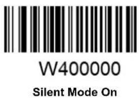
text_image
W400000 Silent Mode On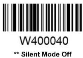
text_image
W400040 ** Silent Mode OffNote: This feature is only applicable to decode beep and will be automatically disabled when the engine is powered down or rebooted.
Illumination

text_image
WOCOOO Off
text_image
W0C0008 Always On
text_image
W0C0004 ** On When ScanningChapter 4 Communication Settings
The engine provides an TTL-232 interface and a USB interface to communicate with the host device. The host device can receive scanned data and send commands to control the engine or to access/alter the configuration information of the engine via the TTL-232 or USB interface.
TTL-232 Interface
Baud Rate
When the engine is connected to a host device through its TTL-232 interface, you need to set communication parameters (including baud rate) to match the host device.
Baud rate is the number of bits of data transmitted per second. Set the engine's baud rate to match the Host requirements.

text_image
WFFD9D3 ** 9600
text_image
WFFD9D0 1200
text_image
WFFD9D1 2400
text_image
WFFD9D2 4800
text_image
WFFD9D4 14400
text_image
WFFD9D5 19200
text_image
WFFD9D6 38400
text_image
WFFD9D7 57600
text_image
WFFD9D8 115200Parity Check

W062900
** None

W062906
Even Parity

W062904
Odd Parity
Stop Bit

W012900
** 1 Stop Bit

W012901
2 Stop Bits
Data Bit

W082908
8 Data Bits

W0F2908
** 8 Data Bits, No Parity, 1 Stop Bit

W0F290E
8 Data Bits, Even Parity, 1 Stop Bit

W0F290C
8 Data Bits, Odd Parity, 1 Stop Bit

W0F2909
8 Data Bits, No Parity, 2 Stop Bits

W0F290F
8 Data Bits, Even Parity, 2 Stop Bits

W0F290D
8 Data Bits, Odd Parity, 2 Stop Bits

W082900
7 Data Bits

W0F2906
7 Data Bits, Even Parity, 1 Stop Bit

W0F2904
7 Data Bits, Odd Parity, 1 Stop Bit

W0F2907
7 Data Bits, Even Parity, 2 Stop Bits

W0F2905
7 Data Bits, Odd Parity, 2 Stop Bits
USB Interface
USB HID-KBW
When enabled, the engine's transmission is simulated as USB keyboard input. It works on a Plug and Play basis and no driver is required.

W070901
** USB HID-KBW
Standard Keyboard

W031A00
** Standard Keyboard
Emulate ALT+Keypad
When Emulate ALT+Keypad is enabled, any ASCII character (0x00 - 0xFF) is sent over the numeric keypad no matter which keyboard type is selected. Since sending a character involves multiple keystroke emulations, this method appears less efficient.
- ALT Make
- Enter the number corresponding to the ASCII character on the keypad.
- ALT Break

W031A03
Emulate ALT+Keypad
Note: It is recommended to turn on the Num Lock light on the host when using this feature.
When Function Key Mapping is enabled, function character (0x00 - 0x1F) are sent as ASCII sequences over the numeric keypad.
- CTRL Make
- Press function key (Refer to the ASCII Function Key Mapping Table on the following page)
- CTRL Break

W031A01
USB Country Keyboard Types
Keyboard layouts vary from country to country. All supported keyboard types are listed below.

WFF1900
** 1 - U.S.

WFF1901
2 - Belgium

WFF1902
3 - Brazil

WFF1903
4 - Canada

WFF1904
5 - Czech

WFF1905
6 - Denmark

WFF1906
7 - Finland

WFF1907
8 - France

WFF1908
9 - Austria

WFF1909
10 - Greece

WFF190A
11 - Hungary

WFF190B
12 - Israel

WFF190C
13 - Italy

WFF190D
14 - Latin America

WFF190E
15 - Netherland

WFF190F
16 - Norway

WFF1910
17 - Poland

WFF1911
18 - Portugal

WFF1912
19 - Romania

WFF1913
20 - Russia

WFF1915
21 - Slovakia

WFF1916
22 - Spain

WFF1917
23 - Sweden

WFF1918
24 - Switzerland

WFF1919
25 - Turkey1

WFF191A
26 - Turkey 2

WFF191B
27 - UK

WFF191C
28 - Japan
Inter-Keystroke Delay
This parameter specifies the delay between emulated keystrokes.

WC01A00
** No Delay

WC01A40
Short Delay (5ms)

WC01A80
Medium Delay (10ms)

WC01AC0
Long Delay (15ms)
Convert Case
This parameter is valid when the Standard Keyboard or Function Key Mapping is enabled.

W381A00
** No Case Conversion

W381A20
Convert All to Upper Case

W381A30
Convert All to Lower Case

W381A08
Invert Upper and Lower Case Characters
Example: When the Invert Upper and Lower Case Characters feature is enabled, barcode data "AbC" is transmitted as "aBc".
Emulate Numeric Keypad
When this feature is disabled, sending barcode data is emulated as keystroke(s) on main keyboard.
To enable this feature, scan the Emulate Numeric Keypad barcode. Sending a number (0-9) is emulated as keystroke on numeric keypad, whereas sending other character like “+”, “_”, “*”, “/” and “.” is still emulated as keystroke on main keyboard. However, this feature is influenced by the state of the Num Lock key on the host: if the Num Lock light on the host is ON, numbers are sent over numeric keypad, if it is OFF, numbers are sent over main keyboard.

W041A04
Emulate Numeric Keypad

W041A00
** Do Not Emulate Numeric Keypad
Note: Make sure the Num Lock light of the Host is turned ON when using this feature.
Emulate ALT+Keypad ON prevails over Emulate Numeric Keypad.
USB DataPipe
A driver is required when using this protocol to communicate with the engine.

text_image
W070900USB DataPipe
USB COM Port Emulation
This feature allows the host to receive data in the way as a serial port does. However, you need to set communication parameters on the engine to match the Host requirements. A driver is required for this feature.

text_image
W070902USB COM Port Emulation
HID-POS
The HID-POS interface is recommended for new application programs. It can send up to 56 characters in a single USB report and appears more efficient than USB HID-KBW.
Features:
✨ HID based, no custom driver required.
* Way more efficient in communication than USB HID-KBW and traditional RS-232 interface.
Note: HID-POS does not require a custom driver. However, a HID interface on Windows 98 does. All HID interfaces employ standard driver provided by the operating system. Use defaults when installing the driver.

text_image
W070903HID-POS
Access the Engine with Your Program
- Use CreateFile to access the engine as a HID device.
- Use ReadFile to deliver the scanned data to the application program.
- Use WriteFile to send data to the engine.
For detailed information about USB and HID interfaces, go to www.USB.org.
Acquire Scanned Data
After a barcode is decoded, the engine sends an input report as below:
| Bit | ||||||||
| Byte | 7 | 6 | 5 | 4 | 3 | 2 | 1 | 0 |
| 0 | Report ID = 02 | |||||||
| 1 | Barcode Length | |||||||
| 2-57 | Decoded Data (1-56) | |||||||
| 58-61 | Reserved (1-4) | |||||||
| 62 | 00 | |||||||
| 63 | 00 (no data continued) or 01 (data continued) | |||||||
VID/PID
USB uses VID (Vendor ID) and PID (Product ID) to identify and locate a device. The VID is assigned by USB Implementers Forum. Newland's vendor ID is 1EAB (Hex). A range of PIDs are used for each Newland product family. Every PID contains a base number and interface type (keyboard, COM port, etc.).
| Product | Interface | PID (Hex) | PID (Dec) |
| EM1399-LD | USB DataPipe | 8001 | 32769 |
| USB HID-KBW | 8003 | 32771 | |
| USB COM Port Emulation | 8006 | 32774 | |
| HID-POS | 8010 | 32784 |
Chapter 5 Prefix & Suffix
Introduction
After a successful barcode read, a string containing numbers, letters or symbols will be returned.
In real applications, barcode data may be found insufficient for your needs. You may wish to include additional information such as barcode type, data acquisition time or delimiter in data being scanned.
Adding extra information to printed barcodes does not seem like a sensible solution since that will increase the barcode size and make them inflexible. Instead, we come up with the idea of appending prefix and suffix to the data without making any change to barcodes. We will show you how to conduct the configuration in the following sections.
Note: Customized data:
Prefix Sequence

W013100
** Code ID+Custom+AIM ID

W013101
Custom+Code ID+ AIM ID
Custom Prefix
Enable/Disable Custom Prefix
If custom prefix is enabled, you are allowed to append to the data a user-defined prefix that cannot exceed 5 characters.
For example, if barcode data is "123" and custom prefix is "AB", the host will receive "AB123".

W043104
Enable Custom Prefix

W043100
** Disable Custom Prefix
Set Custom Prefix
To set a custom prefix, scan the Set Custom Prefix barcode, the numeric barcodes corresponding to the hexadecimal value of a desired prefix and the Save barcode.
Note: A custom prefix cannot exceed 5 characters.

M000100
Set Custom Prefix
Example: Set the custom prefix to "CODE" (its hexadecimal value is 0x43/0x4F/0x44/0x45)
- Scan the Enter Setup barcode.
- Scan the Set Custom Prefix barcode.
- Scan the numeric barcodes "4", "3", "4", "F", "4", "4", "4" and "5". (See the Digit Barcodes section in Appendix)
- Scan the Save barcode. (See the Save/Cancel Barcodes section in Appendix)
- Scan the Enable Custom Prefix barcode.
- Scan the Exit Setup barcode.
AIM ID Prefix
AIM (Automatic Identification Manufacturers) ID defines symbology identifier (For the details, see the AIM ID Table section in Appendix). If AIM ID prefix is enabled, the engine will add the symbology identifier before the scanned data after decoding.

W186018
Enable AIM ID Prefix

W186000
** Disable AIM ID Prefix
CODE ID Prefix
Code ID can also be used to identify barcode type. Unlike AIM ID, Code ID is user programmable. For the information of default Code ID, see the Code ID Table section in Appendix.

W023102
Enable CODE ID Prefix

W023100
** Disable CODE ID Prefix
Restore All Default Code IDs

WFFD9C2
Restore All Default Code IDs
Set Code ID
Code ID can only consist of one or two English letters. To set a Code ID, scan a Set Code ID barcode, the numeric barcodes corresponding to the hexadecimal value of a desired ID and the Save barcode.
Example: Set the Code ID of Code 128 to "p" (its hexadecimal value is 0x70)
- Scan the Enter Setup barcode.
- Scan the Set Code 128 Code ID barcode. (See the barcode on the following page)
- Scan the numeric barcodes "7" and "0". (See the Digit Barcodes section in Appendix)
- Scan the Save barcode. (See the Save/Cancel Barcodes section in Appendix)
- Scan the Exit Setup barcode.
Set Code ID Barcodes

M000200
Set Code 128 Code ID

M000201
Set UCC/EAN-128 Code ID

M000202
Set AIM 128 Code ID

M000204
Set EAN-8 Code ID

M000205
Set EAN-13 Code ID

M000206
Set ISSN Code ID

M000207
Set ISBN Code ID

M000208
Set UPC-E Code ID
Set Code ID Barcodes (continued)

M000209
Set UPC-A Code ID

M00020A
Set Interleaved 2 of 5 Code ID

M00020B
Set ITF-6 Code ID

M00020C
Set ITF-14 Code ID

M00020D
Set Deutsche 14 Code ID

M00020E
Set Deutsche 12 Code ID

M00020F
Set Matrix 2 of 5 Code ID

M000210
Set Industrial 25 Code ID
Set Code ID Barcodes (continued)

M000211
Set Standard 25 Code ID

M000212
Set Code 39 Code ID

M000213
Set Codabar Code ID

M000214
Set Code 93 Code ID

M000215
Set Code 11 Code ID

M000216
Set Plessey Code ID

M000217
Set MSI-Plessey Code ID

M000218
Set RSS-14 Code ID

M000219
Set RSS-Limited Code ID

M00021A
Set RSS-Expand Code ID
Custom Suffix
Enable/Disable Custom Suffix
If custom suffix is enabled, you are allowed to append to the data a user-defined suffix that cannot exceed 5 characters.
For example, if barcode data is "123" and custom suffix is "AB", the host will receive "123AB".

W083108
Enable Custom Suffix

W083100
** Disable Custom Suffix
Set Custom Suffix
To set a custom suffix, scan the Set Custom Suffix barcode, the numeric barcodes corresponding to the hexadecimal value of a desired suffix and the Save barcode.
Note: A custom suffix cannot exceed 5 characters.

M000101
Set Custom Suffix
Example: Set the custom suffix to "CODE" (its hexadecimal value is 0x43/0x4F/0x44/0x45)
- Scan the Enter Setup barcode.
- Scan the Set Custom Suffix barcode.
- Scan the numeric barcodes “4”, “3”, “4”, “F”, “4”, “4”, “4” and “5”. (See the Digit Barcodessection in Appendix)
- Scan the Save barcode. (See the Save/Cancel Barcodes section in Appendix)
- Scan the Enable Custom Suffix barcode.
- Scan the Exit Setup barcode.
Terminating Character Suffix
A terminating character, such as carriage return (CR) and line feed (LF), can be used to mark the end of data, which means nothing can be added after it.
A terminating character suffix cannot exceed 5 characters.
Enable/Disable Terminating Character Suffix
This parameter determines whether to append predefined terminating character suffix to the data.

W103110
** Enable Terminating Character Suffix

W103100
Disable Terminating Character Suffix
Set Terminating Character Suffix
The engine provides a shortcut for setting the terminating character suffix to 0x0D (CR) or 0x0D,0x0A (CRLF) or 0x09 (Horizontal Tab), and enabling it by scanning the appropriate barcode below.

WFFD9C3
Terminating Character 0x0D

WFFD9C4
** Terminating Character 0x0D,0x0A

WFFD9C5
Terminating Character 0x09

M000102
Set Terminating Character Suffix
To set other terminating character suffix, scan the Set Terminating Character Suffix barcode, the numeric barcodes corresponding to the hexadecimal value of a desired terminating character, and the Save barcode.
Note: A terminating character suffix cannot exceed 5 characters.
Example: Set the terminating character suffix to 0x0A (LF)
- Scan the Enter Setup barcode.
- Scan the Set Terminating Character Suffix barcode.
- Scan the numeric barcodes "0" and "A". (See the Digit Barcodes section in Appendix)
- Scan the Save barcode. (See the Save/Cancel Barcodes section in Appendix)
- Scan the Enable Terminating Character Suffix barcode.
- Scan the Exit Setup barcode.
Chapter 6 Symbologies
Introduction
Every symbology (barcode type) has its own unique attributes. This chapter provides programming barcodes for configuring the engine so that it can identify various barcode symbologies. It is recommended to disable those that are rarely used in order to increase the efficiency of the engine.
Global Settings
Enable/Disable All Symbologies
If all symbologies are disabled, the engine can only identify programming barcodes.

WFFD981
Enable All Symbologies

WFFD982
Disable All Symbologies
Video Reverse
Video Reverse allows the engine to read barcodes that are inverted.
Video Reverse ON: Read both regular barcodes and inverse barcodes.
Video Reverse OFF: Read regular barcodes only.

W020D00
** Video Reverse OFF

W020D02
Video Reverse ON
Code 128
Set Length Range for Code 128
The engine can be configured to only decode Code 128 barcodes with lengths that fall between (inclusive) the minimum and maximum lengths.
The supported maximum length is 255 characters. If minimum length is set to be greater than maximum length, the engine only decodes Code 128 barcodes with either the minimum or maximum length. If minimum length is same as maximum length, only Code 128 barcodes with that length are to be decoded.

M000301
Set the Minimum Length

M000300
Set the Maximum Length
Example: Set the engine to decode Code128 barcodes containing between 8 and 12 characters
- Scan the Enter Setup barcode.
- Scan the Set the Minimum Length barcode.
- Scan the numeric barcode "8". (See the Digit Barcodes section in Appendix)
- Scan the Save barcode. (See the Save/Cancel Barcodes section in Appendix)
- Scan the Set the Maximum Length barcode.
- Scan the numeric barcodes "1" and "2".
- Scan the Save barcode.
- Scan the Exit Setup barcode.
UCC/EAN-128
Restore the Factory Defaults of UCC/EAN-128
Enable/Disable UCC/EAN-128

W036203
** Enable UCC/EAN-128

W036200
Disable UCC/EAN-128

W036201
Decode as Code 128
Set Length Range for UCC/EAN-128
The engine can be configured to only decode UCC/EAN-128 barcodes with lengths that fall between (inclusive) the minimum and maximum lengths.
The supported maximum length is 255 characters. If minimum length is set to be greater than maximum length, the engine only decodes UCC/EAN-128 barcodes with either the minimum or maximum length. If minimum length is same as maximum length, only UCC/EAN-128 barcodes with that length are to be decoded.

M000303
Set the Minimum Length

M000302
Set the Maximum Length
Example: Set the engine to decode UCC/EAN-128 barcodes containing between 8 and 12 characters
- Scan the Enter Setup barcode.
- Scan the Set the Minimum Length barcode.
- Scan the numeric barcode "8". (See the Digit Barcodes section in Appendix)
- Scan the Save barcode. (See the Save/Cancel Barcodes section in Appendix)
- Scan the Set the Maximum Length barcode.
- Scan the numeric barcodes "1" and "2".
- Scan the Save barcode.
- Scan the Exit Setup barcode.
AIM 128
Set Length Range for AIM 128
The engine can be configured to only decode AIM 128 barcodes with lengths that fall between (inclusive) the minimum and maximum lengths.
The supported maximum length is 255 characters. If minimum length is set to be greater than maximum length, the engine only decodes AIM 128 barcodes with either the minimum or maximum length. If minimum length is same as maximum length, only AIM 128 barcodes with that length are to be decoded.

M000305
Set the Minimum Length

M000304
Set the Maximum Length
Example: Set the engine to decode AIM128 barcodes containing between 8 and 12 characters
- Scan the Enter Setup barcode.
- Scan the Set the Minimum Length barcode.
- Scan the numeric barcode "8". (See the Digit Barcodes section in Appendix)
- Scan the Save barcode. (See the Save/Cancel Barcodes section in Appendix)
- Scan the Set the Maximum Length barcode.
- Scan the numeric barcodes "1" and "2".
- Scan the Save barcode.
- Scan the Exit Setup barcode.
EAN-8
EAN-8 is 8 digits in length with the last one as its check digit used to verify the integrity of the data.

W046504
** Transmit EAN-8 Check Digit

W046500
Do Not Transmit EAN-8 Check Digit
Add-On Code
An EAN-8 barcode can be augmented with a two-digit or five-digit add-on code to form a new one. In the examples below, the part surrounded by blue dotted line is an EAN-8 barcode while the part circled by red dotted line is add-on code.

text_image
1234 567
text_image
1234 567 89012
text_image
W106510 Enable 2-Digit Add-On Code
text_image
W106500 ** Disable 2-Digit Add-On Code
text_image
W206520 Enable 5-Digit Add-On Code
text_image
W206500 ** Disable 5-Digit Add-On CodeEnable 2-Digit Add-On Code/ Enable 5-Digit Add-On Code: The engine decodes a mix of EAN-8 barcodes with and without 2-digit/5-digit add-on codes.
Disable 2-Digit Add-On Code/ Disable 5-Digit Add-On Code: The engine decodes EAN-8 and ignores the add-on code when presented with an EAN-8 plus add-on barcode. It can also decode EAN-8 barcodes without add-on codes.
Add-On Code Required
This parameter is only valid when Enable 2-Digit Add-On Code and/or Enable 5-Digit Add-On Code is selected.

W086508
EAN-8 Add-On Code Required

W086500
** EAN-8 Add-On Code Not Required
EAN-8 Extension
Disable EAN-8 Zero Extend: Transmit EAN-8 barcodes as is.
Enable EAN-8 Zero Extend: Add five leading zeros to decoded EAN-8 barcodes to extend to 13 digits.
Convert EAN-8 to EAN-13: Add five leading zeros to decoded EAN-8 barcodes to make them compatible in format to EAN-13 barcodes.

WC06540
Enable EAN-8 Zero Extend

WC06500
** Disable EAN-8 Zero Extend

WC06580
Convert EAN-8 to EAN-13
EAN-13
Enable/Disable EAN-13

W016601
** Enable EAN-13

W016600
Disable EAN-13
Transmit Check Digit
EAN-13 is 13 digits in length with the last one as its check digit used to verify the integrity of the data.

W046604
** Transmit EAN-13 Check Digit

W046600
Do Not Transmit EAN-13 Check Digit
Add-On Code
An EAN-13 barcode can be augmented with a two-digit or five-digit add-on code to form a new one. In the examples below, the part surrounded by blue dotted line is an EAN-13 barcode while the part circled by red dotted line is add-on code.

text_image
1 234567 89012 34
text_image
1 234567 89012 45678
text_image
W106610 Enable 2-Digit Add-On Code
text_image
W106600 ** Disable 2-Digit Add-On Code
text_image
W206620 Enable 5-Digit Add-On Code
text_image
W206600 ** Disable 5-Digit Add-On CodeEnable 2-Digit Add-On Code/ Enable 5-Digit Add-On Code: The engine decodes a mix of EAN-13 barcodes with and without 2-digit/5-digit add-on codes.
Disable 2-Digit Add-On Code/ Disable 5-Digit Add-On Code: The engine decodes EAN-13 and ignores the add-on code when presented with an EAN-13 plus add-on barcode. It can also decode EAN-13 barcodes without add-on codes.
Add-On Code Required
This parameter is only valid when Enable 2-Digit Add-On Code and/or Enable 5-Digit Add-On Code is selected.

W086608
EAN-13 Add-On Code Required

W086600
** EAN-13 Add-On Code Not Required
ISSN
UPC-E is 8 digits in length with the last one as its check digit used to verify the integrity of the data.

W046904
** Transmit UPC-E Check Digit

W046900
Do Not Transmit UPC-E Check Digit
Add-On Code
A UPC-E barcode can be augmented with a two-digit or five-digit add-on code to form a new one. In the examples below, the part surrounded by blue dotted line is a UPC-E barcode while the part circled by red dotted line is add-on code.

text_image
0 123456 78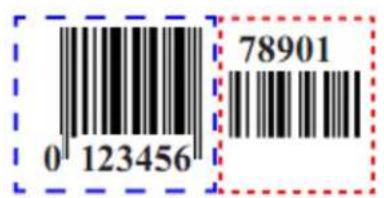
text_image
0 123456 78901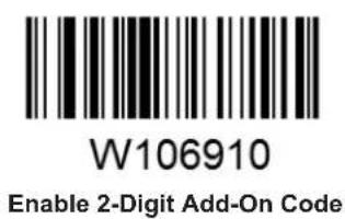
text_image
W106910 Enable 2-Digit Add-On Code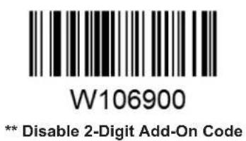
text_image
W106900 ** Disable 2-Digit Add-On Code
text_image
W206920 Enable 5-Digit Add-On Code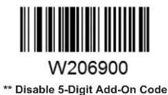
text_image
W206900 ** Disable 5-Digit Add-On CodeEnable 2-Digit Add-On Code/ Enable 5-Digit Add-On Code: The engine decodes a mix of UPC-E barcodes with and without 2-digit/5-digit add-on codes.
Disable 2-Digit Add-On Code/ Disable 5-Digit Add-On Code: The engine decodes UPC-E and ignores the add-on code when presented with a UPC-E plus add-on barcode. It can also decode UPC-E barcodes without add-on codes.
Add-On Code Required
This parameter is only valid when Enable 2-Digit Add-On Code and/or Enable 5-Digit Add-On Code is selected.

W086908
UPC-E Add-On Code Required

W086900
** UPC-E Add-On Code Not Required
Transmit System Character
The first character of UPC-E barcode is the system character.

W306A10
Do Not Transmit System Character

W306A20
** Transmit System Character
UPC-E Extension
Disable UPC-E Extend: Transmit UPC-E barcodes as is.
Enable UPC-E Extend: Extend UPC-E barcodes to make them compatible in length to UPC-A.
Convert UPC-E to UPC-A: Extend UPC-E barcodes to make them compatible in format to UPC-A.

WC06940
Enable UPC-E Extend

WC06900
**Disable UPC-E Extend

WC06980
Convert UPC-E to UPC-A
UPC-A
UPC-A is 13 digits in length with the last one as its check digit used to verify the integrity of the data.

W086B08
** Transmit UPC-A Check Digit

W086B00
Do Not Transmit UPC-A Check Digit
Transmit Preamble Character
Preamble characters (Country Code and System Character) can be transmitted as part of a UPC-A barcode. Select one of the following options for transmitting UPC-A preamble to the host device: transmit system character only, transmit system character and country code ("0" for USA), or transmit no preamble.

W036A00
No Preamble

W036A01
** System Character

W036A02
System Character & Country Code
Add-On Code
A UPC-A barcode can be augmented with a two-digit or five-digit add-on code to form a new one. In the examples below, the part surrounded by blue dotted line is a UPC-A barcode while the part circled by red dotted line is add-on code.
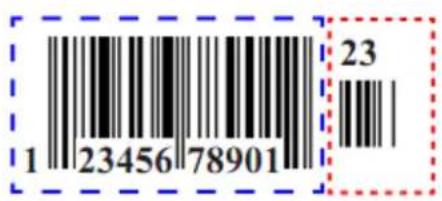
text_image
1 2345678901 23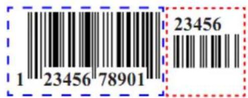
text_image
1 23456 78901 23456
text_image
W206B20Enable 2-Digit Add-On Code

text_image
W206B00** Disable 2-Digit Add-On Code

text_image
W406B40Enable 5-Digit Add-On Code

text_image
W406B00** Disable 5-Digit Add-On Code
Enable 2-Digit Add-On Code/ Enable 5-Digit Add-On Code: The engine decodes a mix of UPC-A barcodes with and without 2-digit/5-digit add-on codes.
Disable 2-Digit Add-On Code/ Disable 5-Digit Add-On Code: The engine decodes UPC-A and ignores the add-on code when presented with a UPC-A plus add-on barcode. It can also decode UPC-A barcodes without add-on codes.
Add-On Code Required
This parameter is only valid when Enable 2-Digit Add-On Code and/or Enable 5-Digit Add-On Code is selected.

W106B10
UPC-A Add-On Code Required

W106B00
** UPC-A Add-On Code Not Required
Interleaved 2 of 5
Restore the Factory Defaults of Interleaved 2 of 5
Enable/Disable Interleaved 2 of 5

W016C01
** Enable Interleaved 2 of 5

W016C00
Disable Interleaved 2 of 5
Check Digit Verification
A check digit is optional for Interleaved 2 of 5 and can be added as the last digit. It is a calculated value used to verify the integrity of the data.
Disable: The engine transmits Interleaved 2 of 5 barcodes as is.
Do Not Transmit Check Digit After Verification: The engine checks the integrity of all Interleaved 2 of 5 barcodes to verify that the data complies with the check digit algorithm. Barcodes passing the check will be transmitted except the last digit, whereas those failing it will not be transmitted.
Transmit Check Digit After Verification: The engine checks the integrity of all Interleaved 2 of 5 barcodes to verify that the data complies with the check digit algorithm. Barcodes passing the check will be transmitted, whereas those failing it will not be transmitted.

text_image
W0C6C00Disable

W0C6C04
** Do Not Transmit Check Digit After Verification

W0C6C0C
Transmit Check Digit After Verification
Set Length Range for Interleaved 2 of 5
The engine can be configured to only decode Interleaved 2 of 5 barcodes with lengths that fall between (inclusive) the minimum and maximum lengths.
The supported maximum length is 255 characters. If minimum length is set to be greater than maximum length, the engine only decodes Interleaved 2 of 5 barcodes with either the minimum or maximum length. If minimum length is same as maximum length, only Interleaved 2 of 5 barcodes with that length are to be decoded.

M000307
Set the Minimum Length

M000306
Set the Maximum Length
Example: Set the engine to decode Interleaved 2 of 5 barcodes containing between 8 and 12 characters
- Scan the Enter Setup barcode.
- Scan the Set the Minimum Length barcode.
- Scan the numeric barcode "8". (See the Digit Barcodes section in Appendix)
- Scan the Save barcode. (See the Save/Cancel Barcodes section in Appendix)
- Scan the Set the Maximum Length barcode.
- Scan the numeric barcodes "1" and "2".
- Scan the Save barcode.
- Scan the Exit Setup barcode.
ITF-6
ITF-6 is a special kind of Interleaved 2 of 5 with a length of 6 characters and the last character as the check character.
Restore the Factory Defaults of ITF-6
Enable/Disable ITF-6
By default, ITF-6 is decoded as Interleaved 2 of 5.

W036D01
Disable ITF-6

W0B6D02
Enable ITF-6 But Do Not Transmit Check Digit

W0B6D0A
Enable ITF-6 and Transmit Check Digit
Note: It is advised not to enable ITF-6 and Interleaved 2 of 5 at the same time.
ITF-14
ITF-14 is a special kind of Interleaved 2 of 5 with a length of 14 characters and the last character as the check character.
By default, ITF-14 is decoded as Interleaved 2 of 5.

W036E01
Disable ITF-14

W0B6E02
Enable ITF-14 But Do Not Transmit Check Digit

W0B6E0A
Enable ITF-14 and Transmit Check Digit
Note: It is advised not to enable ITF-14 and Interleaved 2 of 5 at the same time.
Deutsche 14
By default, Deutsche 14 is decoded as Interleaved 2 of 5.

W036F01
Disable Deutsche 14

W0B6F02
Enable Deutsche 14 But Do Not Transmit Check Digit

WOB6FOA
Enable Deutsche 14 and Transmit Check Digit
Note: It is advised not to enable Deutsche 14 unless necessary, because Deutsche 14, ITF-14 and Interleaved 2 of 5 use the same encoding method and enabling them at the same time can easily cause confusion with each other when decoding.
Deutsche 12
By default, Deutsche 12 is decoded as Interleaved 2 of 5.

W037001
Disable Deutsche 12

W0B7002
Enable Deutsche 12 But Do Not Transmit Check Digit

W0B700A
Enable Deutsche 12 and Transmit Check Digit
Note: It is advised not to enable Deutsche 12 unless necessary, because Deutsche 12, ITF-12 and Interleaved 2 of 5 use the same encoding method and enabling them at the same time can easily cause confusion with each other when decoding.
Matrix 2 of 5 (European Matrix 2 of 5)
Restore the Factory Defaults of Matrix 2 of 5
Enable/Disable Matrix 2 of 5

W017101
** Enable Matrix 2 of 5

W017100
Disable Matrix 2 of 5
Check Digit Verification
A check digit is optional for Matrix 2 of 5 and can be added as the last digit. It is a calculated value used to verify the integrity of the data.
Disable: The engine transmits Matrix 2 of 5 barcodes as is.
Do Not Transmit Check Digit After Verification: The engine checks the integrity of all Matrix 2 of 5 barcodes to verify that the data complies with the check digit algorithm. Barcodes passing the check will be transmitted except the last digit, whereas those failing it will not be transmitted.
Transmit Check Digit After Verification: The engine checks the integrity of all Matrix 2 of 5 barcodes to verify that the data complies with the check digit algorithm. Barcodes passing the check will be transmitted, whereas those failing it will not be transmitted.

W0C7100
** Disable

W0C7104
Do Not Transmit Check Digit After Verification

W0C710C
Transmit Check Digit After Verification
Set Length Range for Matrix 2 of 5
The engine can be configured to only decode Matrix 2 of 5 barcodes with lengths that fall between (inclusive) the minimum and maximum lengths.
The supported maximum length is 255 characters. If minimum length is set to be greater than maximum length, the engine only decodes Matrix 2 of 5 barcodes with either the minimum or maximum length. If minimum length is same as maximum length, only Matrix 2 of 5 barcodes with that length are to be decoded.

M000309
Set the Minimum Length

M000308
Set the Maximum Length
Example: Set the engine to decode Matrix 2 of 5 barcodes containing between 8 and 12 characters
- Scan the Enter Setup barcode.
- Scan the Set the Minimum Length barcode.
- Scan the numeric barcode "8". (See the Digit Barcodes section in Appendix)
- Scan the Save barcode. (See the Save/Cancel Barcodes section in Appendix)
- Scan the Set the Maximum Length barcode.
- Scan the numeric barcodes "1" and "2".
- Scan the Save barcode.
- Scan the Exit Setup barcode.
Industrial 25
Restore the Factory Defaults of Industrial 25
Enable/Disable Industrial 25

W017201
** Enable Industrial 25

W017200
Disable Industrial 25
Check Digit Verification
A check digit is optional for Industrial 25 and can be added as the last digit. It is a calculated value used to verify the integrity of the data.
Disable: The engine transmits Industrial 25 barcodes as is.
Do Not Transmit Check Digit After Verification: The engine checks the integrity of all Industrial 25 barcodes to verify that the data complies with the check digit algorithm. Barcodes passing the check will be transmitted except the last digit, whereas those failing it will not be transmitted.
Transmit Check Digit After Verification: The engine checks the integrity of all Industrial 25 barcodes to verify that the data complies with the check digit algorithm. Barcodes passing the check will be transmitted, whereas those failing it will not be transmitted.

text_image
W0C7200 ** Disable
text_image
W0C7204Do Not Transmit Check Digit After Verification

text_image
W0C720CTransmit Check Digit After Verification
Set Length Range for Industrial 25
The engine can be configured to only decode Industrial 25 barcodes with lengths that fall between (inclusive) the minimum and maximum lengths.
The supported maximum length is 255 characters. If minimum length is set to be greater than maximum length, the engine only decodes Industrial 25 barcodes with either the minimum or maximum length. If minimum length is same as maximum length, only Industrial 25 barcodes with that length are to be decoded.

M00030B
Set the Minimum Length

M00030A
Set the Maximum Length
Example: Set the engine to decode Industrial 25 barcodes containing between 8 and 12 characters
- Scan the Enter Setup barcode.
- Scan the Set the Minimum Length barcode.
- Scan the numeric barcode "8". (See the Digit Barcodes section in Appendix)
- Scan the Save barcode. (See the Save/Cancel Barcodes section in Appendix)
- Scan the Set the Maximum Length barcode.
- Scan the numeric barcodes "1" and "2".
- Scan the Save barcode.
- Scan the Exit Setup barcode.
Standard 25
Check Digit Verification
A check digit is optional for Standard 25 and can be added as the last digit. It is a calculated value used to verify the integrity of the data.
Disable: The engine transmits Standard 25 barcodes as is.
Do Not Transmit Check Digit After Verification: The engine checks the integrity of all Standard 25 barcodes to verify that the data complies with the check digit algorithm. Barcodes passing the check will be transmitted except the last digit, whereas those failing it will not be transmitted.
Transmit Check Digit After Verification: The engine checks the integrity of all Standard 25 barcodes to verify that the data complies with the check digit algorithm. Barcodes passing the check will be transmitted, whereas those failing it will not be transmitted.

W0C7300
** Disable

W0C7304
Do Not Transmit Check Digit After Verification

W0C730C
Transmit Check Digit After Verification
Set Length Range for Standard 25
The engine can be configured to only decode Standard 25 barcodes with lengths that fall between (inclusive) the minimum and maximum lengths.
The supported maximum length is 255 characters. If minimum length is set to be greater than maximum length, the engine only decodes Standard 25 barcodes with either the minimum or maximum length. If minimum length is same as maximum length, only Standard 25 barcodes with that length are to be decoded.

M00030D
Set the Minimum Length

M00030C
Set the Maximum Length
Example: Set the engine to decode Standard 25 barcodes containing between 8 and 12 characters
- Scan the Enter Setup barcode.
- Scan the Set the Minimum Length barcode.
- Scan the numeric barcode "8". (See the Digit Barcodes section in Appendix)
- Scan the Save barcode. (See the Save/Cancel Barcodes section in Appendix)
- Scan the Set the Maximum Length barcode.
- Scan the numeric barcodes "1" and "2".
- Scan the Save barcode.
- Scan the Exit Setup barcode.
Code 39
Check Digit Verification
A check digit is optional for Code 39 and can be added as the last digit. It is a calculated value used to verify the integrity of the data.
Disable: The engine transmits Code 39 barcodes as is.
Do Not Transmit Check Digit After Verification: The engine checks the integrity of all Code 39 barcodes to verify that the data complies with the check digit algorithm. Barcodes passing the check will be transmitted except the last digit, whereas those failing it will not be transmitted.
Transmit Check Digit After Verification: The engine checks the integrity of all Code 39 barcodes to verify that the data complies with the check digit algorithm. Barcodes passing the check will be transmitted, whereas those failing it will not be transmitted.

W187400
** Disable

W187408
Do Not Transmit Check Digit After Verification

W187418
Transmit Check Digit After Verification
Transmit Start/Stop Characters
Code 39 uses an asterisk (*) for both the start and the stop characters. You can choose whether or not to transmit the start/stop characters by scanning the appropriate barcode below.

W047404
Transmit Start/Stop Characters

W047400
** Do Not Transmit Start/Stop Characters
Enable/Disable Code 39 Full ASCII
The engine can be configured to identify all ASCII characters by scanning the appropriate barcode below.

W207420
** Enable Code 39 Full ASCII

W207400
Disable Code 39 Full ASCII
Set Length Range for Code 39
The engine can be configured to only decode Code 39 barcodes with lengths that fall between (inclusive) the minimum and maximum lengths.
The supported maximum length is 255 characters. If minimum length is set to be greater than maximum length, the engine only decodes Code 39 barcodes with either the minimum or maximum length. If minimum length is same as maximum length, only Code 39 barcodes with that length are to be decoded.

M00030F
Set the Minimum Length

MM00030E
Set the Maximum Length
Example: Set the engine to decode Code 39 barcodes containing between 8 and 12 characters.
- Scan the Enter Setup barcode.
- Scan the Set the Minimum Length barcode.
- Scan the numeric barcode "8". (See the Digit Barcodes section in Appendix)
- Scan the Save barcode. (See the Save/Cancel Barcodes section in Appendix)
- Scan the Set the Maximum Length barcode.
- Scan the numeric barcode "1".
- Scan the numeric barcode "2".
- Scan the Save barcode.
- Scan the Exit Setup barcode.
Codabar
Check Digit Verification
A check digit is optional for Codabar and can be added as the last digit. It is a calculated value used to verify the integrity of the data.
Disable: The engine transmits Codabar barcodes as is.
Do Not Transmit Check Digit After Verification: The engine checks the integrity of all Codabar barcodes to verify that the data complies with the check digit algorithm. Barcodes passing the check will be transmitted except the last digit, whereas those failing it will not be transmitted.
Transmit Check Digit After Verification: The engine checks the integrity of all Codabar barcodes to verify that the data complies with the check digit algorithm. Barcodes passing the check will be transmitted, whereas those failing it will not be transmitted.

text_image
W607500 ** Disable
text_image
W607520Do Not Transmit Check Digit After Verification

text_image
W607560Transmit Check Digit After Verification
Start/Stop Characters

W047504
** Transmit Start/Stop Characters

W047500
Do Not Transmit Start/Stop Characters

W187500
** ABCD/ABCD as the Start/Stop Character

W187508
ABCD/TN*E as the Start/Stop Character

W187510
abcd/abcd as the Start/Stop Character

W187518
abcd/tn*e as the Start/Stop Character
Set Length Range for Codabar
The engine can be configured to only decode Codabar barcodes with lengths that fall between (inclusive) the minimum and maximum lengths.
The supported maximum length is 255 characters. If minimum length is set to be greater than maximum length, the engine only decodes Codabar barcodes with either the minimum or maximum length. If minimum length is same as maximum length, only Codabar barcodes with that length are to be decoded.

M000311
Set the Minimum Length

M000310
Set the Maximum Length
Example: Set the engine to decode Codabar barcodes containing between 8 and 12 characters.
- Scan the Enter Setup barcode.
- Scan the Set the Minimum Length barcode.
- Scan the numeric barcode "8". (See the Digit Barcodes section in Appendix)
- Scan the Save barcode. (See the Save/Cancel Barcodes section in Appendix)
- Scan the Set the Maximum Length barcode.
- Scan the numeric barcode "1".
- Scan the numeric barcode "2".
- Scan the Save barcode.
- Scan the Exit Setup barcode.
Code 93
Check Digit Verification
Check digits are optional for Code 93 and can be added as the last two digits, which are calculated values used to verify the integrity of the data.
Disable: The engine transmits Code 93 barcodes as is.
Do Not Transmit Check Digit After Verification: The engine checks the integrity of all Code 93 barcodes to verify that the data complies with the check digit algorithm. Barcodes passing the checks will be transmitted except the last two digits, whereas those failing them will not be transmitted.
Transmit Check Digit After Verification: The engine checks the integrity of all Code 93 barcodes to verify that the data complies with the check digit algorithm. Barcodes passing the checks will be transmitted, whereas those failing them will not be transmitted.

W0C7600
Disable

W0C7604
** Do Not Transmit Check Digit After Verification

W0C760C
Transmit Check Digit After Verification
Set Length Range for Code 93
The engine can be configured to only decode Code 93 barcodes with lengths that fall between (inclusive) the minimum and maximum lengths.
The supported maximum length is 255 characters. If minimum length is set to be greater than maximum length, the engine only decodes Code 93 barcodes with either the minimum or maximum length. If minimum length is same as maximum length, only Code 93 barcodes with that length are to be decoded.

M000313
Set the Minimum Length

M000312
Set the Maximum Length
Example: Set the engine to decode Code 93 barcodes containing between 8 and 12 characters.
- Scan the Enter Setup barcode.
- Scan the Set the Minimum Length barcode.
- Scan the numeric barcode "8". (See the Digit Barcodes section in Appendix)
- Scan the Save barcode. (See the Save/Cancel Barcodes section in Appendix)
- Scan the Set the Maximum Length barcode.
- Scan the numeric barcode "1".
- Scan the numeric barcode "2".
- Scan the Save barcode.
- Scan the Exit Setup barcode.
Code 11
Check Digit Verification
Check digits are optional for Code 11 and can be added as the last one or two digits, which are calculated values used to verify the integrity of the data.
If the Disable option is enabled, the engine transmits Code 11 barcodes as is.

text_image
W1C7700Disable

text_image
W1C7704** One Check Digit, MOD11

W1C7708
Two Check Digits, MOD11/MOD11

W1C770C
Two Check Digits, MOD11/MOD9

W1C7710
One Check Digit, MOD11 (Len <= 11)
Two Check Digits, MOD11/MOD11 (Len > 11)

W1C7714
One Check Digit, MOD11 (Len <= 11)
Two Check Digits, MOD11/MOD9 (Len > 11)

W207720
Transmit Check Digit

W207700
** Do Not Transmit Check Digit
Set Length Range for Code 11
The engine can be configured to only decode Code 11 barcodes with lengths that fall between (inclusive) the minimum and maximum lengths.
The supported maximum length is 255 characters. If minimum length is set to be greater than maximum length, the engine only decodes Code 11 barcodes with either the minimum or maximum length. If minimum length is same as maximum length, only Code 11 barcodes with that length are to be decoded.

M000315
Set the Minimum Length

M000314
Set the Maximum Length
Example: Set the engine to decode Code 11 barcodes containing between 8 and 12 characters.
- Scan the Enter Setup barcode.
- Scan the Set the Minimum Length barcode.
- Scan the numeric barcode "8". (See the Digit Barcodes section in Appendix)
- Scan the Save barcode. (See the Save/Cancel Barcodes section in Appendix)
- Scan the Set the Maximum Length barcode.
- Scan the numeric barcode "1".
- Scan the numeric barcode "2".
- Scan the Save barcode.
- Scan the Exit Setup barcode.
Plessey
Check Digit Verification
Check digits are optional for Plessey and can be added as the last one or two digits, which are calculated values used to verify the integrity of the data.
Disable: The engine transmits Plessey barcodes as is.
Do Not Transmit Check Digit After Verification: The engine checks the integrity of all Plessey barcodes to verify that the data complies with the check digit algorithm. Barcodes passing the checks will be transmitted except the last two digits, whereas those failing them will not be transmitted.
Transmit Check Digit After Verification: The engine checks the integrity of all Plessey barcodes to verify that the data complies with the check digit algorithm. Barcodes passing the checks will be transmitted, whereas those failing them will not be transmitted.

text_image
W0C7800Disable

W0C7804
** Do Not Transmit Check Digit After Verification

W0C780C
Transmit Check Digit After Verification
Set Length Range for Plessey
The engine can be configured to only decode Plessey barcodes with lengths that fall between (inclusive) the minimum and maximum lengths.
The supported maximum length is 255 characters. If minimum length is set to be greater than maximum length, the engine only decodes Plessey barcodes with either the minimum or maximum length. If minimum length is same as maximum length, only Plessey barcodes with that length are to be decoded.

M000317
Set the Minimum Length

M000316
Set the Maximum Length
Example: Set the engine to decode Plessey barcodes containing between 8 and 12 characters.
- Scan the Enter Setup barcode.
- Scan the Set the Minimum Length barcode.
- Scan the numeric barcode "8". (See the Digit Barcodes section in Appendix)
- Scan the Save barcode. (See the Save/Cancel Barcodes section in Appendix)
- Scan the Set the Maximum Length barcode.
- Scan the numeric barcode "1".
- Scan the numeric barcode "2".
- Scan the Save barcode.
- Scan the Exit Setup barcode.
MSI-Plessey
Check Digit Verification
Check digits are optional for MSI-Plessey and can be added as the last one or two digits, which are calculated values used to verify the integrity of the data.
If the Disable option is enabled, the engine transmits MSI-Plessey barcodes as is.

W0C7900
Disable

W0C7904
** One Check Digit, MOD10

W0C7908
Two Check Digits, MOD10/MOD10

W0C790C
Two Check Digits, MOD10/MOD11

W107910
Transmit Check Digit

W107900
** Do Not Transmit Check Digit
Set Length Range for MSI-Plessey
The engine can be configured to only decode MSI-Plessey barcodes with lengths that fall between (inclusive) the minimum and maximum lengths.
The supported maximum length is 255 characters. If minimum length is set to be greater than maximum length, the engine only decodes MSI-Plessey barcodes with either the minimum or maximum length. If minimum length is same as maximum length, only MSI-Plessey barcodes with that length are to be decoded.

M000319
Set the Minimum Length

M000318
Set the Maximum Length
Example: Set the engine to decode MSI-Plessey barcodes containing between 8 and 12 characters.
- Scan the Enter Setup barcode.
- Scan the Set the Minimum Length barcode.
- Scan the numeric barcode "8". (See the Digit Barcodes section in Appendix)
- Scan the Save barcode. (See the Save/Cancel Barcodes section in Appendix)
- Scan the Set the Maximum Length barcode.
- Scan the numeric barcode "1".
- Scan the numeric barcode "2".
- Scan the Save barcode.
- Scan the Exit Setup barcode.
RSS-14
Transmit Application Identifier "01"

W047A04
** Transmit Application Identifier "01"

W047A00
Do Not Transmit Application Identifier "01"
RSS-Limited
Enable/Disable RSS-Limited

W017B01
** Enable RSS-Limited

W017B00
Disable RSS-Limited
Transmit Application Identifier "01"

W047B04
** Transmit Application Identifier "01"

W047B00
Do Not Transmit Application Identifier "01"
RSS-Expand
| Parameter | Factory Default | Remark | |
| System Settings | |||
| Barcode Programming | Enabled | ||
| Programming Barcode Data | Do not send | ||
| Scan Mode | Manual Mode | ||
| Manual Mode | Decode Session Timeout | 15s | 1-255s; 0: infinite. |
| Continuous Mode | Decode Session Timeout | 15s | 1-255s; 0: infinite. |
| Timeout between Decodes | 1.0s | 0.0-25.5s | |
| Reread Same Barcode | With no delay | To disable rereads of same barcode, enable the Reread Same Barcode with a Delay and set the delay to 0. | |
| Sense Mode | Decode Session Timeout | 15s | 1-255s; 0: infinite. |
| Image Stabilization Timeout | 0.4s | 0.0-25.5s | |
| Reread Same Barcode | With no delay | To disable rereads of same barcode, enable the Reread Same Barcode with a Delay and set the delay to 0. | |
| Sensitivity | Medium | ||
| Command Trigger Mode | Decode Session Timeout | 15s | 1-255s; 0: infinite. |
| Security Level | 0 | ||
| Good Read Beep | Enabled | ||
| Good Read Beep Frequency | Medium | ||
| Good Read Beep Duration | 80ms | ||
| Decode Result Notification | Disabled | ||
| Silent Mode | Disabled | Temporary setting | |
| Illumination | On When Scanning | Temporary setting | |
| Communication Interfaces | |||
| TTL-232 Interface | Baud Rate | 9600 | |
| Parity Check | None | ||
| Number of Data Bits | 8 | ||
| Number of Stop Bits | 1 | ||
| Flow Control | None | ||
| USB Interface | USB HID-KBW | Other options: DataPipe, USB COM Port Emulation, HID-POS | |
| USB HID-KBW | Input Mode | Standard Keyboard | |
| USB Country Keyboard Type | U.S. | ||
| Inter-Keystroke Delay | No Delay | ||
| Convert Case | No Conversion | ||
| Emulate Numeric Keypad | Disabled | ||
| Prefix & Suffix | |||
| Prefix Sequence | Code ID+Custom+AIM ID | ||
| AIM ID Prefix | Disabled | ||
| Code ID Prefix | Disabled | 1 or 2 English letters | |
| Custom Prefix | Disabled | 1 to 5 characters | |
| Custom Suffix | Disabled | 1 to 5 characters | |
| Terminating Character Suffix | Enabled, 0x0D,0x0A | 0x0D,0x0A: CRLF | |
| Parameter | Factory Default | Remark |
| Symbologies | ||
| Video Reverse | Disabled | Applicable to all symbologies. |
| Code 128 | ||
| Code 128 | Enabled | |
| Minimum Length | 1 | No less than 1 (including check digit) |
| Maximum Length | 80 | |
| UCC/EAN-128 (GS1-128) | ||
| UCC/EAN-128 | Enabled | |
| Minimum Length | 1 | No less than 1 (including check digit) |
| Maximum Length | 80 | |
| AIM 128 | ||
| AIM 128 | Disabled | |
| Minimum Length | 1 | No less than 1 (including check digit) |
| Maximum Length | 80 | |
| EAN-8 | ||
| EAN-8 | Enabled | |
| Check Digit | Transmit | |
| 2-Digit Add-On Code | Disabled | |
| 5-Digit Add-On Code | Disabled | |
| Add-On Code | Not required | |
| Extend to EAN-13 | Disabled | |
| EAN-13 | ||
| EAN-13 | Enabled | |
| Check Digit | Transmit | |
| 2-Digit Add-On Code | Disabled | |
| 5-Digit Add-On Code | Disabled | |
| Add-On Code | Not required | |
| ISSN | ||
| ISSN | Disabled | |
| ISBN | ||
| ISBN | Disabled | |
| ISBN Format | ISBN-13 | |
| UPC-E | ||
| UPC-E | Enabled | |
| Check Digit | Transmit | |
| 2-Digit Add-On Code | Disabled | |
| 5-Digit Add-On Code | Disabled | |
| Add-On Code | Not required | |
| Extend to UPC-A | Disabled | |
| System Character | Transmit | |
| UPC-A | ||
| UPC-A | Enabled | |
| Check Digit | Transmit | |
| 2-Digit Add-On Code | Disabled | |
| 5-Digit Add-On Code | Disabled | |
| Add-On Code | Not required | |
| Transmit Preamble Character | System character | |
| Interleaved 2 of 5 | ||
| Interleaved 2 of 5 | Enabled | |
| Check Digit Verification | Enabled | |
| Check Digit | Do not transmit | |
| Minimum Length | 6 | No less than 3 (including check digit) |
| Maximum Length | 100 | |
| ITF-6 | ||
| ITF-6 | Decode as I25 | |
| Check Digit | Transmit | |
| ITF-14 | ||
| ITF-14 | Decode as I25 | |
| Check Digit | Transmit | |
| Deutsche 14 | ||
| Deutsche 14 | Decode as I25 | |
| Check Digit | Transmit | |
| Deutsche 12 | ||
| Deutsche 12 | Decode as I25 | |
| Check Digit | Transmit | |
| Matrix 2 of 5 | ||
| Matrix 2 of 5 | Enabled | |
| Check Digit Verification | Disabled | |
| Check Digit | Do not transmit | |
| Minimum Length | 6 | No less than 2 (including check digit) |
| Maximum Length | 80 | |
| Industrial 25 | ||
| Industrial 25 | Enabled | |
| Check Digit Verification | Disabled | |
| Check Digit | Do not transmit | |
| Minimum Length | 6 | No less than 2 (including check digit) |
| Maximum Length | 80 | |
| Standard 25 | ||
| Standard 25 | Enabled | |
| Check Digit Verification | Disabled | |
| Check Digit | Do not transmit | |
| Minimum Length | 6 | No less than 2 (including check digit) |
| Maximum Length | 80 | |
| Code 39 | ||
| Code 39 | Enabled | |
| Check Digit Verification | Disabled | |
| Check Digit | Do not transmit | |
| Start/Stop Characters | Do not transmit | |
| Code 39 Full ASCII | Enabled | |
| Minimum Length | 4 | No less than 2 (including check digit) |
| Maximum Length | 50 | |
| Codabar | ||
| Codabar | Enabled | |
| Check Digit Verification | Disabled | |
| Check Digit | Do not transmit | |
| Start/Stop Characters | Transmit | |
| Start/Stop Character Format | ABCD/ABCD | |
| Minimum Length | 4 | No less than 1 (including check digit) |
| Maximum Length | 60 | |
| Code 93 | ||
| Code 93 | Enabled | |
| Check Digit Verification | Enabled | |
| Check Digit | Do not transmit | |
| Minimum Length | 2 | No less than 1 (including check digit) |
| Maximum Length | 80 | |
| Code 11 | ||
| Code 11 | Disabled | |
| Check Digit Verification | One check digit, MOD11 | |
| Check Digit | Do not transmit | |
| Minimum Length | 4 | No less than 2 (including check digit) |
| Maximum Length | 80 | |
| Plessey | ||
| Plessey | Disabled | |
| Check Digit Verification | Enabled | |
| Check Digit | Do not transmit | |
| Minimum Length | 4 | No less than 3 (including check digit) |
| Maximum Length | 60 | |
| MSI-Plessey | ||
| MSI-Plessey | Disabled | |
| Check Digit Verification | One check digit, MOD10 | |
| Check Digit | Do not transmit | |
| Minimum Length | 4 | No less than 2 (including check digit) |
| Maximum Length | 60 | |
| RSS-14 | ||
| RSS-14 | Enabled | |
| AI (Application Identifier) | Transmit | |
| RSS-Limited | ||
| RSS-Limited | Enabled | |
| AI (Application Identifier) | Transmit | |
| RSS-Expand | ||
| RSS-Expand | Enabled | |
AIM ID Table
| Symbology | AIM ID | Remark |
| Code 128 | ]C0 | Standard Code 128 |
| UCC/EAN 128(GS1-128) | ]C1 | FNC1 is the character right after the start character |
| AIM 128 | ]C2 | FNC1 is the 2nd character after the start character |
| EAN-8 | ]E4 | Standard EAN-8 |
| ]E4....]E1... | EAN-8 + 2-Digit Add-On Code | |
| ]E4....]E2... | EAN-8 + 5-Digit Add-On Code | |
| EAN-13 | ]E0 | Standard EAN-13 |
| ]E3 | EAN-13 + 2/5-Digit Add-On Code | |
| ISSN | ]X5 | |
| ISBN | ]X4 | |
| UPC-E | ]E0 | Standard UPC-E |
| ]E3 | UPC-E + 2/5-Digit Add-On Code | |
| UPC-A | ]E0 | Standard UPC-A |
| ]E3 | UPC-A + 2/5-Digit Add-On Code | |
| Interleaved 2 of 5 | ]I0 | No check digit verification |
| ]I1 | Transmit check digit after verification | |
| ]I3 | Do not transmit check digit after verification | |
| ITF-6 | ]I1 | Transmit check digit |
| ]I3 | Do not transmit check digit | |
| ITF-14 | ]I1 | Transmit check digit |
| ]I3 | Do not transmit check digit | |
| Deutsche 14Deutsche 12 | ]X0 | |
| Matrix 2 of 5 | ]X1 | No check digit verification |
| ]X2 | Transmit check digit after verification | |
| ]X3 | Do not transmit check digit after verification | |
| Industrial 25 | ]S0 | Not specified |
| Standard 25 | ]R0 | No check digit verification |
| ]R8 | One check digit, MOD 7; do not transmit check digit | |
| ]R9 | One check digit, MOD 7; transmit check digit | |
| Code 39 | ]A0 | Transmit barcodes as is; Full ASCII disabled; no check digit verification |
| ]A1 | One check digit, MOD 43; transmit check digit | |
| ]A3 | One check digit, MOD 43; do not transmit check digit | |
| ]A4 | Full ASCII enabled; no check digit verification | |
| ]A5 | Full ASCII enabled; MOD43; transmit check digit | |
| ]A7 | Full ASCII enabled; MOD43; do not transmit check digit | |
| Codabar | ]F0 | Standard Codabar |
| ]F1 | ABC Codabar | |
| ]F2 | Transmit check digit after verification | |
| ]F4 | Do not transmit check digit after verification | |
| Code 93 | ]G0 | Not specified |
| Code 11 | ]H0 | One check digit, MOD11; transmit check digit |
| ]H1 | Two check digits, MOD11/MOD11; transmit check digit | |
| ]H3 | Do not transmit check digit after verification | |
| ]H8 | Two check digits, MOD11/MOD9; transmit check digit | |
| ]H9 | No check digit verification | |
| Plessey | ]P0 | Not specified |
| MSI Plessey | ]M0 | One check digit, MOD10; transmit check digit |
| ]M1 | One check digit, MOD10; do not transmit check digit | |
| ]M7 | Two check digits, MOD10 /MOD11; do not transmit check digit | |
| ]M8 | Two check digits, MOD10 /MOD11; transmit check digit | |
| ]M9 | No check digit verification | |
| RSS-14/RSS-Limited RSS-Expand | ]e0 | Standard |
| ]e1 | User-defined | |
| ]e2 | User-defined | |
| ]e3 | User-defined |
Reference: ISO/IEC 15424:2008 Information technology – Automatic identification and data capture techniques – Data Carrier Identifiers (including Symbology Identifiers)
Code ID Table
| Symbology | Code ID |
| Code 128 | j |
| UCC/EAN-128 | u |
| AIM 128 | f |
| SETTING 128 | t |
| EAN-8 | g |
| EAN-13 | d |
| ISSN | n |
| ISBN | B |
| UPC-E | h |
| UPC-A | c |
| Interleaved 2 of 5 | e |
| ITF-6 | r |
| ITF-14 | q |
| Deutsche 14 | w |
| Deutsche 12 | l |
| Matrix 2 of 5(European Matrix 2 of 5) | v |
| Industrial 25 | i |
| Standard 25 | s |
| Code 39 | b |
| Codabar | a |
| Code 93 | y |
| Code 11 | z |
| Plessey | p |
| MSI-Plessey | m |
| RSS-14 | D |
| RSS-Limited | C |
| RSS-Expand | R |
ASCII Table
| Hex | Dec | Char | |
| 00 | 0 | NUL | (Null char.) |
| 01 | 1 | SOH | (Start of Header) |
| 02 | 2 | STX | (Start of Text) |
| 03 | 3 | ETX | (End of Text) |
| 04 | 4 | EOT | (End of Transmission) |
| 05 | 5 | ENQ | (Enquiry) |
| 06 | 6 | ACK | (Acknowledgment) |
| 07 | 7 | BEL | (Bell) |
| 08 | 8 | BS | (Backspace) |
| 09 | 9 | HT | (Horizontal Tab) |
| 0a | 10 | LF | (Line Feed) |
| 0b | 11 | VT | (Vertical Tab) |
| 0c | 12 | FF | (Form Feed) |
| 0d | 13 | CR | (Carriage Return) |
| 0e | 14 | SO | (Shift Out) |
| 0f | 15 | SI | (Shift In) |
| 10 | 16 | DLE | (Data Link Escape) |
| 11 | 17 | DC1 | (XON) (Device Control 1) |
| 12 | 18 | DC2 | (Device Control 2) |
| 13 | 19 | DC3 | (XOFF) (Device Control 3) |
| 14 | 20 | DC4 | (Device Control 4) |
| 15 | 21 | NAK | (Negative Acknowledgment) |
| 16 | 22 | SYN | (Synchronous Idle) |
| 17 | 23 | ETB | (End of Trans. Block) |
| 18 | 24 | CAN | (Cancel) |
| 19 | 25 | EM | (End of Medium) |
| 1a | 26 | SUB | (Substitute) |
| 1b | 27 | ESC | (Escape) |
| 1c | 28 | FS | (File Separator) |
| 1d | 29 | GS | (Group Separator) |
| 1e | 30 | RS | (Request to Send) |
| 1f | 31 | US | (Unit Separator) |
| 20 | 32 | SP | (Space) |
| 21 | 33 | ! | (Exclamation Mark) |
| 22 | 34 | " | (Double Quote) |
| 23 | 35 | # | (Number Sign) |
| 24 | 36 | $ | (Dollar Sign) |
| 25 | 37 | % | (Percent) |
| 26 | 38 | & | (Ampersand) |
| 27 | 39 | ` | (Single Quote) |
| 28 | 40 | ( | (Left / Opening Parenthesis) |
| 29 | 41 | ) | (Right / Closing Parenthesis) |
| 2a | 42 | * | (Asterisk) |
| 2b | 43 | + | (Plus) |
| 2c | 44 | , | (Comma) |
| 2d | 45 | - | (Minus / Dash) |
| 2e | 46 | . | (Dot) |
| 2f | 47 | / | (Forward Slash) |
| 30 | 48 | 0 | |
| 31 | 49 | 1 | |
| 32 | 50 | 2 | |
| 33 | 51 | 3 | |
| 34 | 52 | 4 | |
| 35 | 53 | 5 | |
| 36 | 54 | 6 | |
| 37 | 55 | 7 | |
| 38 | 56 | 8 | |
| 39 | 57 | 9 | |
| 3a | 58 | : | (Colon) |
| 3b | 59 | ; | (Semi-colon) |
| 3c | 60 | < | (Less Than) |
| 3d | 61 | = | (Equal Sign) |
| Hex | Dec | Char |
| 3e | 62 | (Greater Than) |
| 3f | 63 | (Question Mark) |
| 40 | 64 | (AT Symbol) |
| 41 | 65 | A |
| 42 | 66 | B |
| 43 | 67 | C |
| 44 | 68 | D |
| 45 | 69 | E |
| 46 | 70 | F |
| 47 | 71 | G |
| 48 | 72 | H |
| 49 | 73 | I |
| 4a | 74 | J |
| 4b | 75 | K |
| 4c | 76 | L |
| 4d | 77 | M |
| 4e | 78 | N |
| 4f | 79 | O |
| 50 | 80 | P |
| 51 | 81 | Q |
| 52 | 82 | R |
| 53 | 83 | S |
| 54 | 84 | T |
| 55 | 85 | U |
| 56 | 86 | V |
| 57 | 87 | W |
| 58 | 88 | X |
| 59 | 89 | Y |
| 5a | 90 | Z |
| 5b | 91 | (Left / Opening Bracket) |
| 5c | 92 | (Back Slash) |
| 5d | 93 | (Right / Closing Bracket) |
| 5e | 94 | ^ (Caret / Circumflex) |
| 5f | 95 | _ (Underscore) |
| 60 | 96 | ' (Grave Accent) |
| 61 | 97 | a |
| 62 | 98 | b |
| 63 | 99 | c |
| 64 | 100 | d |
| 65 | 101 | e |
| 66 | 102 | f |
| 67 | 103 | g |
| 68 | 104 | h |
| 69 | 105 | i |
| 6a | 106 | j |
| 6b | 107 | k |
| 6c | 108 | l |
| 6d | 109 | m |
| 6e | 110 | n |
| 6f | 111 | o |
| 70 | 112 | p |
| 71 | 113 | q |
| 72 | 114 | r |
| 73 | 115 | s |
| 74 | 116 | t |
| 75 | 117 | u |
| 76 | 118 | v |
| 77 | 119 | w |
| 78 | 120 | x |
| 79 | 121 | y |
| 7a | 122 | z |
| 7b | 123 | { (Left/ Opening Brace) |
| 7c | 124 | | (Vertical Bar) |
| 7d | 125 | } (Right/Closing Brace) |
| 7e | 126 | ~ (Tilde) |
| 7f | 127 | DEL (Delete) |
Digit Barcodes
0\~5

text_image
D0000000

text_image
D000011

text_image
D0000022

text_image
D000033

text_image
D0000044

text_image
D000055
6\~9

text_image
D000066

text_image
D0000077

text_image
D0000088

text_image
D0000099
A \~ F

text_image
D0000AA

text_image
D0000BB

text_image
D0000CC

text_image
D0000DD

text_image
D0000EE

text_image
D0000FF
Save/Cancel Barcodes
After reading numeric barcode(s), you need to scan the Save barcode to save the data. If you scan the wrong digit(s), you can either scan the Cancel the Last Digit barcode and then the correct digit, or scan the Cancel All Digits barcode and then the digits you want.
For instance, after reading the Decode Session Timeout barcode and numeric barcodes "1", "2" and "3", you scan:
Cancel the Last Digit: The last digit "3" will be removed.
Cancel All Digits: All digits "123" will be removed.

text_image
D000012Save

text_image
D000010Cancel the Last Digit

text_image
D000011Cancel All Digits
F1\~F12
When the USB HID-KBW feature is enabled, scanning one of the following barcodes will send the corresponding function key.
F1\~F6
text_image
F000000 F1
text_image
F000001 F2
text_image
F000002 F3
text_image
F000003 F4
text_image
F000004 F5
text_image
F000005 F6F7\~F12
text_image
F00006 F7
text_image
F000007 F8
text_image
F000008 F9
text_image
F000009 F10
text_image
F00000A F11
text_image
F00000B F12
Newland
SCANNING MADE SIMPLE
Newland EMEA HQ
+31 (0) 345 87 00 33
info@newland-id.com
newland-id.com
D-A-C-H
+49 (0) 6182 82916-16
info@newland-id.de
Benelux
+31 (0) 345 87 00 33
benelux@newland-id.com
Italy
+39 (0) 342 0562227
italy@newland-id.com
United Kingdom
+44 (0) 1442 212020
sales@newland-id.co.uk
South Africa
Gauteng: +27 (0) 11 553 8010
Cape Town: +27 (0) 21 9140819
info@newland-id.co.za
Turkey
+90 (0) 544 538 40 49
turkey@newland-id.com
France
+39(0)3458804096
france@newland-id.com
Ibérica
+34 (0) 93 303 74 66
info@newland-id.es
Nordic & Baltic
+46 (0) 70 88 47 767
nordic@newland-id.com
Russia
+31(0)345870033
russia@newland-id.com
Middle East
+39 (0) 345 8804096
middleeast@newland-id.com
Iran
+90 (0) 544 538 40 49
iran@newland-id.com