Evolution EVO-05NSD - Security Camera Pelco - Free user manual and instructions
Find the device manual for free Evolution EVO-05NSD Pelco in PDF.


| Product Type | Security Camera (IP Fisheye) |
| Brand | Pelco |
| Model | Evolution EVO-05NSD |
| Sensor Resolution | 5 MP effective; streams at up to 4 MP (2144x1944) |
| Lens Type | Fisheye (fixed) |
| Field of View | 360° horizontal, 180° vertical |
| Video Compression | H.264 and MJPEG |
| Maximum Frame Rate | 30 fps at 1 MP resolution (1056x960) |
| Power Supply | PoE (IEEE 802.3af) or 12 VDC, 1 A |
| Audio Input | 3.5 mm stereo jack (electret microphone) |
| Alarm I/O | 1 input, 1 output (hardwired) |
| Storage | SD/SDHC/SDXC card up to 128 GB (Class 10 or higher) |
| Network Interface | 10/100Base-T Ethernet (RJ45) |
| Mounting Options | Ceiling, wall, table, pendant, corner, pole |
| Ingress Protection | IP66 (outdoor models) / IP40 (indoor recessed) |
| Vandal Resistance | IK10 (outdoor models) |
| Operating Temperature | -10°C to 50°C (typical) |
| Web Interface | Yes (browsers: Internet Explorer, Edge, Safari, Firefox) |
| ONVIF Profile S | Yes |
| Privacy Masking | Up to 10 regions |
Frequently Asked Questions - Evolution EVO-05NSD Pelco
User questions about Evolution EVO-05NSD Pelco
0 question about this device. Answer the ones you know or ask your own.
Ask a new question about this device
Download the instructions for your Security Camera in PDF format for free! Find your manual Evolution EVO-05NSD - Pelco and take your electronic device back in hand. On this page are published all the documents necessary for the use of your device. Evolution EVO-05NSD by Pelco.
USER MANUAL Evolution EVO-05NSD Pelco
Evolution 05 Camera Range
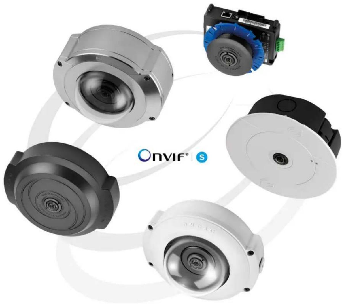
natural_image
Product display of four optical cameras with visible lens and control components, arranged in a circular arrangement (no text or symbols on main objects)Installation & User Manual
© Oncam Global Group AG, 2013 - 2016. All rights reserved.
C3983M-E
December 2016
Manual Copyright
© Oncam Global Group AG, 2013 - 2016. All rights reserved.
No part of this manual may be reproduced except for your express personal use.
Oncam and their affiliate's further reserve the right to alter, amend or revise this document and any product specifications without any obligation to provide notice of such changes.
Oncam and its affiliates make no guarantee, representation or warranty, either expressed or implied, regarding the accuracy of the information contained in this manual. Furthermore, Oncam and its affiliates assume no responsibility or any potential liability for any errors that may appear in this manual.
Trademarks and Third-Party Copyrights
Oncam and the Oncam logo are registered trademarks of Oncam Global Group AG.
Oncam and the IPZoom logos are trademarks of Oncam Global Group AG (and its affiliates).
SATIV is a service mark of Oncam Global Group (and its affiliates).
The names of other companies, organizations, products or services mentioned in this manual are the trademarks of their respective owners.

Important Safety Instructions
-
Read these instructions.
-
Keep these instructions.
-
Heed all warnings.
-
Follow all instructions.
-
Do not immerse in water. Protect the connectors from moisture.
-
Do not block any ventilation openings, Install in accordance with the manufacturer's instructions.
-
Do not install near any heat sources such as radiators, heat registers, stoves, or other apparatus (including amplifiers) that produce heat.
-
The polarity of any connector attached to the product should be verified before connection.
-
Protect all cables from being crushed or pinched particularly at plugs, convenience receptacles, and the point where they exit from the apparatus.
-
Only use attachments / accessories specified by the manufacturer.
-
Unplug or appropriately protect this apparatus during lighting storms or when unused for long periods of time.
-
Refer all servicing to qualified service personnel. Servicing is required when the apparatus has been damaged in any way, such as power-supply cord or plug is damaged, liquid has been spilled or objects have fallen into the apparatus, the apparatus has been exposed to rain or moisture, does not operate normally, or has been dropped.

WARNING
RISK OF EXPLOSION IF REPLACING A BATTERY WITH AN INCORRECT BATTERY TYPE
Contents
1 Overview....5
1.1 Fisheye View 5
1.2 Panoramic View 5
1.3 Camera Range....5
1.4 Power Requirements....6
1.5 Audio Input 6
1.6 Alarms....6
2 Camera Placement and Orientation....7
2.1 Ceiling Mount 7
2.2 Wall Mount....7
2.3 Table Mount....8
2.4 Coverage Area 8
2.5 Overhead Viewing Angle 8
2.6 Lighting 8
3 Camera Installation 9
3.1 Preparation....9
3.2 Indoor Camera 11
3.3 Indoor Concealed Camera....13
3.4 Indoor Recessed Camera....15
3.5 Outdoor Camera....18
3.6 Stainless Steel Camera – Surface Mount 21
3.7 Stainless Steel Camera – Pendant Mount 23
4 Camera Mounts....25
4.1 Wall Mount....25
4.2 Corner Mount 26
4.3 Pole Mount 27
4.4 Pendant Mount....28
5 Test....29
5.1 Indoor Camera 29
5.2 Outdoor Camera....29
6 Dome Handling and Cleaning....30
7 First Time Operation 30
7.1 DHCP....30
7.2 Static IP Installation....30
7.3 Finding Available Cameras....31
7.4 Assigning an IP Address....31
7.5 Connecting to the Camera....32
7.6 Media Player Requirements....32
8 Camera Web Interface....33
8.1 Control Panel....33
8.2 Image....34
8.3 Administration....37
8.4 Regions....48
9 Connecting directly to the camera streams....51
9.1 JPEG Snapshot....51
9.2 MJPEG / H.264 Video Stream....52
10 Connecting through ONVIF Profile S or PSIA....52
11 Troubleshooting and Technical Support....53
11.1 Contact 53
11.2 Revision History....53
12 Copyright and Legal Notices....54
13 Additional Online Resources 55
13.1 Technical Specifications ....55
13.2 Oncam 360-degree Viewer....55
13.3 OnVu360 Mobile Application (iOS and Android)....56
14 Frame Rate, Resolution & Storage Requirements....57
15 NVR and Storage Partners....57
List of Figures
Figure 1 Indoor Camera Exploded View....11
Figure 2 Indoor Concealed Camera Exploded View 13
Figure 3 Indoor Recessed Camera Exploded View....15
Figure 4 Indoor Recessed Overview....16
Figure 5 Indoor Recessed Below Ceiling Installation....17
Figure 6 Outdoor Camera Exploded View....18
Figure 7 Stainless Steel Camera – Surface Mount Exploded View....21
Figure 8 Stainless Steel Camera – Pendant Mount Exploded View....23
Figure 9 Wall Mount Exploded View....25
Figure 10 Corner Mount Exploded View....26
Figure 11 Pole Mount Exploded View....27
Figure 12 Pendant Mount Exploded View 28
Figure 13 Oncam Grandeye Camera Configuration Tool ....31
Figure 14 Color Hysteresis Curve 35
Figure 15 Administration Settings....37
Figure 16 Network Settings....38
Figure 17 Alarm Settings Triggers ....39
Figure 18 Alarm Settings Actions....40
Figure 19 Alarm Settings Actions – E-Mail ....40
Figure 20 Alarm Settings Actions – FTP 41
Figure 21 Alarm Settings Actions – Record to SD-Card ....41
Figure 22 Camera Settings – MJPEG....42
Figure 23 Camera Settings – H.264....42
Figure 24 Clock Settings 43
Figure 25 Stream Settings....44
Figure 26 Audio Dialog....45
Figure 27 Recordings Dialog....45
Figure 28 Camera Configuration Tool – Reset to Factory Defaults....47
Figure 29 Region Settings....48
List of Tables
Table 1 Main Camera Stream Maximum Frame Rates....44
Table 2 Main and Second Camera Maximum Frame Rates....44
1 Overview
The Oncam Evolution 05 IP Series cameras are innovative and use a fisheye lens to create a 360° view with an extremely large area of coverage. The Oncam 360° IP camera may replace two or more conventional fixed cameras for seamless coverage of an entire scene with no gaps or blind spots. The ability to see in all directions at once makes Oncam 360° IP cameras ideally suited for total situational awareness.
The 5-megapixel sensor produces enough detail to allow digital pan/tilt/zoom (PTZ) operations over the entire field of view (FoV). Unlike conventional PTZ cameras, Oncam 360° IP cameras are silent. Oncam 360° IP cameras have no mechanical motors or gears prone to wear and failure. The camera produces three types of views, each suited to a particular set of requirements.
The Evolution 05 design allows for easy and fast installation into the corresponding camera module housing options.
1.1 Fisheye View
The high quality fisheye lens produces a spherical image from which derive all other views. The raw image appears warped around a central axis. Special dewarping software built into the NVR / VMS converts the spherical image into a flat view that is more familiar to human viewers. When using video management software (VMS) to record a fisheye video stream, the entire image is preserved. You can retrospectively look at all directions regardless of the live or recorded viewed area after an incident.
1.2 Panoramic View
When using compatible VMS or NVR software integrated with the Oncam dewarping SDK, it is possible to generate a double 180-degree panoramic view from fisheye overview. The fisheye image is dewarped and split into two 180-degree bands for simpler viewing of the overall image.
Note: Due to the dewarping image cropping, the area directly underneath the camera is not visible. The camera does not generate the 180-degree panoramic view. The camera requires a compatible client machine with software to produce this panoramic view.
1.3 Camera Range
Configure the camera module for either an H.264 or MJPEG single stream.
• 10 FPS (maximum) with a frame size of 2144 x 1944 pixels (4 MP)
• 15 FPS (maximum) with a frame size of 1488 x 1360 pixels (2 MP)
• 30 FPS (maximum) with a frame size of 1056 x 960 pixels (1 MP)
• 30 FPS (maximum) with a frame size of 528 x 480 pixels (1/4 MP)
Enable and configure a second H.264 fisheye stream. If enabling the second stream, the maximum frame rates are reduced for both the main and second stream.
Simultaneously access a third MJPEG stream at a fixed FPS and a frame size of 528 x 480 pixels (1/4 MP).
1.4 Power Requirements
Supply power in two ways using either Power over Ethernet (PoE) or Direct DC Input.
PoE. Connect power and data using a single cable, plugged into the camera Ethernet port. The PoE supplied equipment must be compliant with IEEE 802.3af.
Direct DC Input. Use only a UL/CSA-approved LPS or NEC Class 2 power source with a 12 VDC 1A AC adapter (not supplied). Connect to the camera through the 12 VDC socket. This connector is a 2.1 mm positive center jack.
CAUTION: Do not use an excess of 12 VDC from an external power supply. Doing so may damage the camera and void the warranty.
1.5 Audio Input
The camera mic input follows the computer industry standard for PC mic inputs. The physical connector is a 3.5 mm stereo audio jack. As wired, it works with an ordinary Electret microphone.
Audio Input connects the camera module to an electret microphone in close proximity to the enclosure. The electret microphone and the connecting cable must be electrically floating to prevent noise and hum from ground loops.
Suggested cable length is 1 meter or less. Any length longer than this results in noise interference with the audio.
Contact Oncam for compatible microphones and splitters.
1.6 Alarms
The camera module has 1x input and 1x output hardware alarms connected through a hardwire plug connector.
2 Camera Placement and Orientation
Camera placement is an important factor when planning your deployment. The Evolution 05 camera has an exceptionally wide viewing angle. Consider the camera location for providing comprehensive coverage of a wide area. Mount the camera with an unobstructed view and consider scene optimization when one portion of the scene is bright and another dark.
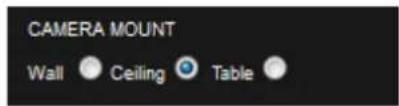
The camera supports three different mounting orientations, Ceiling, Wall and Table. Each of these options require correct orientation settings selected from the Camera Web Interface. These camera settings ensure using the correct dewarping algorithm when connecting to a compatible VMS or NVR system.
2.1 Ceiling Mount
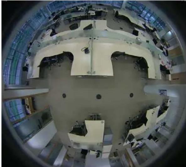
Ceiling mounting is preferred when most of the action is occurring below the camera in a horizontal plane. When a person is directly below the camera, captured is the top-of head view. When the person moves away from the camera, more of their face and body becomes visible.
Depending on the use case, use a single camera to cover a small to medium sized room. Mounting a camera high gives great situational awareness throughout a large room. When planning coverage ensure there are no obstructions. Some obstructions include pillars, high-sided furniture and any hanging objects near the camera such as signage.
natural_image
Interior view of a large, multi-level industrial or laboratory facility with structural components and machinery (no visible text or symbols)2.2 Wall Mount
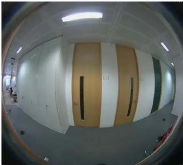
Wall mounting the camera can give a complete 180-degree side on view of an area. Use this view where ceiling mounting is not possible or if you need to capture a higher level of detail for objects closer to the camera (such as people's faces as they walk past the camera).
natural_image
Interior view of a modern office or library space with white walls and vertical wooden panels, no visible text or symbols.2.3 Table Mount
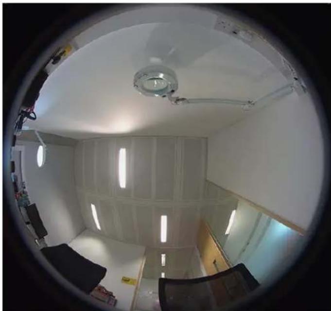
Install the Table Mount camera on a flat surface looking up. This configuration is for demonstration or testing purposes. You could use the Table Mount for inspecting systems or viewing under vehicles.
natural_image
Interior view through a circular frame showing a room with ceiling lights, white walls, and a chair (no visible text or symbols)2.4 Coverage Area
The Evolution 05 cameras provide coverage for open areas where situational awareness of people and objects are required.
The higher camera placement provides a larger coverage area. However, with higher camera placement a reduction in the pixel density is expected. Height impacts the image detail available, therefore ensure you consider image quality versus the mounting height.
Perform tests to ensure that the camera meets the system operational requirements and the required detail level is available.
Use a minimum height of 2 m (6.5 ft.) when ceiling mounting a camera for best results.
For multiple camera layouts, ensure the camera areas overlap for full coverage.
2.5 Overhead Viewing Angle
Ceiling-mounted cameras capture a top-of-head shot when the person is directly under the camera. Hats extend that top-of-head zone to some degree. Consider the viewing angle when requiring people identification or recognition.
2.6 Lighting
Avoid bright light sources pointing towards the camera lens. Always face lighting away from the camera or above the camera installation line (if ceiling mounted).
Adjust the auto-sensor in the camera from the Web Interface. Using auto-sensor adjusts the camera continuously to optimize the image by increasing exposure time. Furthermore, the maximum frame rate is reduced as exposure time increases. The image remains in full color until below one Lux, after which it transitions to black and white for better contrast.
3 Camera Installation
For installation of your Oncam Evolution 05 camera, provided are the following instructions. Reference the Camera Web Interface, page 33 for a more detailed features and functionality.
3.1 Preparation
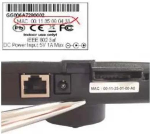
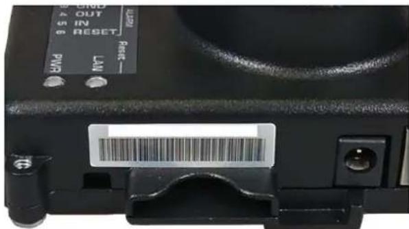
Document the camera's location and MAC address for camera configuration. Find the MAC address on a sticker on the side and rear of the camera module.
3.1.1 Inserting an SD card
Configure an SD card for recording alarm-triggered events. The SD card slot is located on the side of the camera module.
Compatible SD cards
- SD, SDHC, SDXC
- Up to 128 GB max capacity
• Speed of Class 10 or higher
The camera uses the format EXT3, while most SD cards use the format FAT32. Therefore, it is necessary to format the SD card to EXT3 prior to using the first time.
Use the camera to format the SD card for an EXT3 file system using the Camera Web Interface. See Recordings, page 45.
In addition, you may use a computer to format several SD cards for an EXT3 file system. While additional software is required, this method may be faster.
3.1.2 Ethernet and Power Cabling
See Outdoor Camera, page 18 for Ethernet cable preparation instructions.
NOTICE: The cable must be round, otherwise the grommet will not seal around the cable.
3.1.3 External I/O Cabling
When connecting an external I/O, first remove the multi-way connector block for wiring.
![1 On - Diagnostics 1 Off - Normal [Default] 2 On - N/A 2 Off - N/A [Default] 1 2 GND OUT IN RESET 1 2 3 4 5 6 ALARM Reset —— LAN PWR](/content/2026/06/1204764/images/07f46bec0253b697f0da24f6625e1093c484d49c5d00278f069c51c65b08c6d4.jpg)
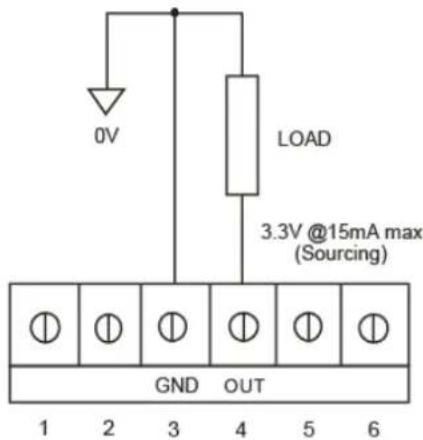
3.1.4 Alarm Out
When an event occurs triggering an external alarm on the camera, the Alarm OUT pin outputs a signal (Low to High). Use this signal to drive the external alarm circuit (known as sourcing). The signal is 3.3VDC at 15 mA (max).
3.1.5 Alarm In
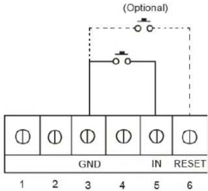
When Alarm IN shorts to GND, the camera's internal alarm triggers. Through the Camera Web Interface, specify the time duration. Options include 10, 30, 60, 300 or 600 seconds.
After the specified amount of time has passed, the internal alarm clears.
The Alarm RESET pin is optional. Use the Alarm RESET pin for overriding the counter in order to clear the internal alarm before the specified amount by shorting to GND.
3.2 Indoor Camera
The Indoor camera is for indoor surface (ceiling, wall and table) applications. The camera uses a metal Mounting Plate and plastic Trim Cover to enclose the Camera Module and wiring.
The die cast metal Mounting Plate attaches to the surface for mounting together the Camera Module and the Trim Cover.
Using the optional Pendant Mount, attach the camera directly to any length of pipe (1.5-inch NPT). This is popular for high ceiling installations.
Route wires into the enclosure from either the back or the side.
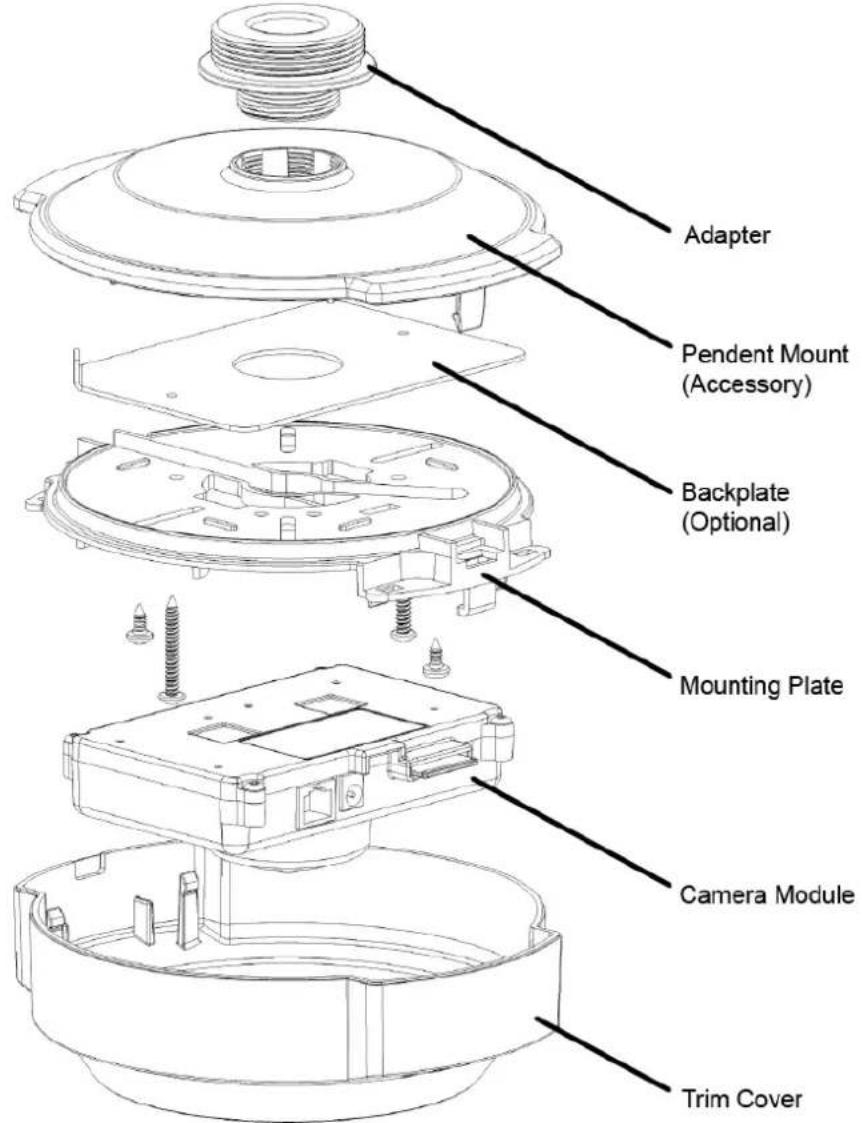
Figure 1 Indoor Camera Exploded View
3.2.1 Parts List
- Mounting Plate
- Camera Module
-
Trim Cover
-
Quick Start Guide
- Drilling Template
3.2.2 Installation Steps
- Attach the Mounting Plate to a wall or ceiling surface through the holes and slots located on the plate.
- Ensure the fasteners are appropriate for the surface material and support at least four times the weight of the camera and assembled enclosure. Use the backplate to secure the camera, if required.
- The enclosure covers a mounting surface hole or box through which you pull the wires. The Mounting Plate has holes and slots to allow for mounting directly to most European or American standard electrical boxes.
natural_image
Close-up of a mechanical component with black and white parts, possibly a valve or clamp, against a light background (no visible text or symbols)-
If the indoor installation is subject to vandalism, use the Evolution Outdoor camera that is IK10 vandal resistant. Only use the indoor enclosure when vandalism is not an issue.
-
Pull wires through the center hole in the Mounting Plate.
-
Secure the Mounting Plate to the surface.
-
Consider the orientation of the Mounting Plate as this determines the fisheye image orientation and affects where the elongated ears of the cover are oriented. For reference, the thumbscrew that fixes the Camera Module to the Mounting Plate corresponds to the top of the fisheye image (unless rotated in the firmware).
-
Pass the Ethernet cable around the Camera Module; secure the cable by clicking the connector into position.
-
Route wires under, around or over the Camera Module to the connection points. Remove the alarm connector (if used) from the Camera Module to facilitate connection and service.
-
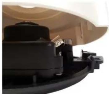
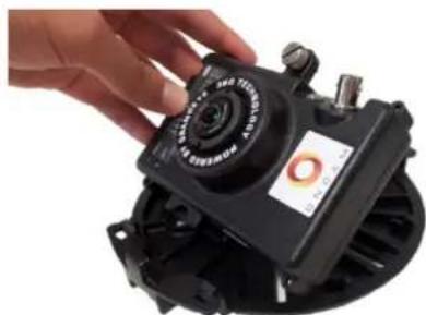
Install the Camera Module by rotating the camera into the clip in the Mounting Plate.
-
Fasten the Camera Module in place with the captive thumbscrew.
natural_image
Hand holding a black industrial fan or sensor device with a circular dial and label (no readable text or symbols)- Route wires without crossing over the lens area when attaching the Trim Cover.
Note: A BNC video connector is present for factory use only and is disabled.
-
Fasten the cover in place by orienting the elongated ears of the cover with the tabs on the mounting plate.
-
Push the cover until it snaps in place.
To remove the cover, grasp the sides and pull away from the Mounting Plate.
For installations where the wiring is from the side, there is a thin section of plastic on the cover at one end. Remove the plastic with pliers. Route wiring in this case through the tunnel in the mounting plate.
For mounting options, see Camera Mounts page 25.
3.3 Indoor Concealed Camera
The Evolution Indoor Concealed camera is for indoor use in ceiling applications. The concealed model consists of the Camera Module, plastic Locking Nut and plastic Bezel.
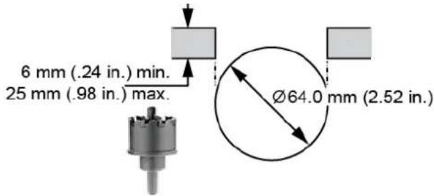
Mount the Indoor Concealed camera to a surface thickness between 6 mm (1/4-inch) and 25 mm (1-inch) using a Bezel and Locking Nut that attaches to the front cover.
The Locking Nut sandwiches the surface material between the Bezel and Locking Nut. This camera requires access from above the ceiling or behind the wall to install and maintain while providing a minimal presence.
The only portion of the camera visible below the ceiling is the lens and Bezel (black or white). Spray-paint the plastic Bezel with a suitable paint to coordinate with your installation environment.
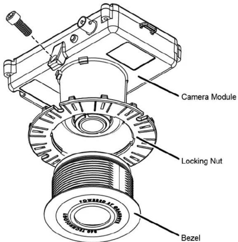
Figure 2 Indoor Concealed Camera Exploded View
3.3.1 Parts List
- Camera Module
- Locking Nut
- Bezel
- Quick Start Guide
3.3.2 Installation Steps
The Indoor Concealed camera requires access to the space above the ceiling.
Note: Ensure the ceiling material is strong to support four times the weight of the camera and cabling. Otherwise, use a suitable stiffener, such as a metal plate, above the ceiling surface.
- Using the supplied template for the installation location, mark the hole.
- Remove the ceiling panel and cut a hole to accept the 64 mm (2.52 in.) Bezel.
-
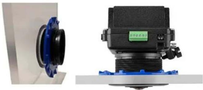
Insert the Bezel through the hole from the front of the cut out (Lens side). Use one hand and with the other hand fit the blue Locking Nut to the rear securing the Bezel in place. In a solid ceiling, hold both parts and fastened from the top.
-
Ensure the Locking Nut is correctly orientated so the smooth side is against the surface of the ceiling material and the finger grips are exposed.
natural_image
Two industrial mechanical components: a blue flange component and a black cylindrical device with threaded shaft (no visible text or symbols)- Do not over tighten the Locking Nut.
- Insert the Camera Module into the Bezel from above once the Bezel is tight. Slide the Camera Module into the rear of the Bezel.
Note: Ensure the camera is correctly oriented since this affects where the edges of the image are oriented in the resulting full screen picture. Ensure the top of the image corresponds to the orientation of the camera.
-
Tighten the thumb screw to fix the camera in the desired position.
-
Pass the Ethernet cable around the Camera Module; secure the cable by clicking the connector into position.
-
Route the wires under and then around or over the camera to the connection points. Remove the alarm connector from the camera (if used) to facilitate connection and service.
Note: A BNC video connector is present for factory use only and is not enabled in production firmware.
- Fasten all wiring to a nearby ceiling member ensuring there are no torque forces acting on the camera.
NOTICE: The camera is not plenum rated. Installing the camera within air-handling spaces may invalidate the warranty.
3.4 Indoor Recessed Camera
The Evolution Indoor Recessed camera allows for easy and fast installation to an indoor. The camera is an IP40-rated surface mount device and is suitable for internal use only. The Indoor Recessed camera is UL2043 certified for installation in an air handling space.
The enclosure is constructed of an aluminium die cast base, with the electronics PCB encased by a plastic inner shield mounted to the base. The plastic trim cover may be painted to match the interior.
The Evolution 05 Indoor Recessed camera provides recessed mounting in drop ceilings or walls with a maximum cross section of 1"/25.4mm. The die-cast base contains two spring-loaded flaps for retaining the camera once inserted in the mounting hole.
The Evolution Indoor Recessed camera enclosure is for surface mounts. The camera consists of the camera module, a die-cast aluminium base and an outer trim injection moulded cover.
Remove the camera's trim cover and paint the cover to blend with the installation environment.
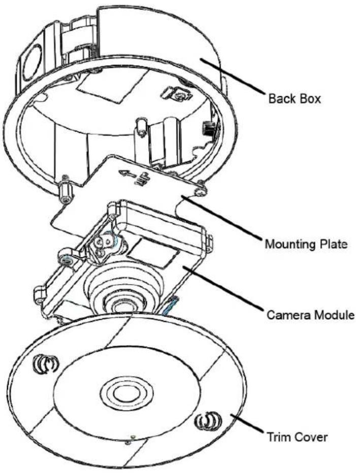
Figure 3 Indoor Recessed Camera Exploded View
3.4.1 Parts List
- Camera Module
- Trim Cover
-
Back Box
-
Quick Start Guide
- Drilling Template
The Evolution 05 Indoor Recessed camera is a recessed mounting for drop ceilings or walls with a maximum cross section of 25.4 mm (1-inch).
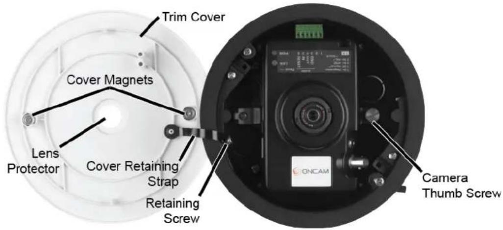
Figure 4 Indoor Recessed Overview
- Remove the camera cover.
- Detach the cover retaining strap from the casing by removing the retaining nut.
- Remove the camera by loosening the thumb screw.
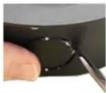
- Remove the cable entry cover. Cable side and top options are available.
- Cut a 152 mm (6-inch) hole in the mounting location. A template is supplied.
natural_image
Close-up of a finger holding a black circular object with a metal tool inserted (no visible text or symbols)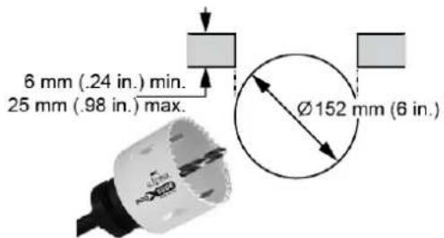
-
Pass the Ethernet cable through the cable entry hole in the casing.
-
Adjust the casing and insert the casing into the pre-made hole.
-
Secure the casing by tightening the two screws engaging the two retention fins.
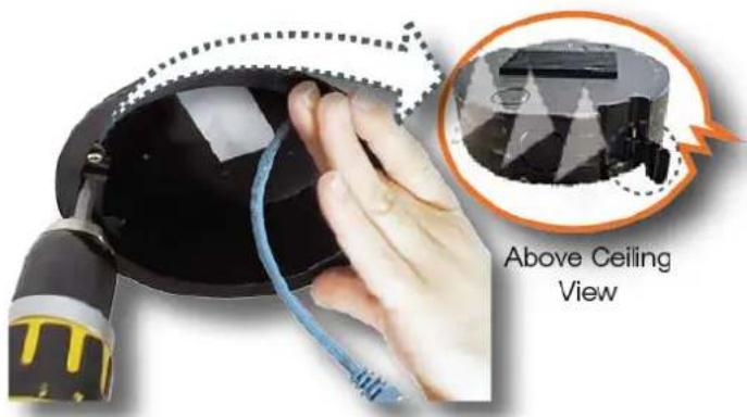
Figure 5 Indoor Recessed Below Ceiling Installation
- Connect the Ethernet cable to the camera and reinsert the camera into the casing. Fasten the thumb screw firmly.
- Reattach the cover retaining strap with the retaining nut.
- Aligning the magnets, place the cover on the casing.
- Remove the lens protector.
- Ensure the LED lights illuminate.
3.5 Outdoor Camera
The Evolution Outdoor Dome camera is IP-66 rated and vandal resistant. The Trim Cover and Base Assembly prevents reaching the camera. All mounting perforations are outside the enclosures sealed area.
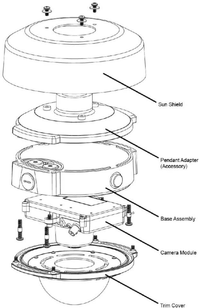
Figure 6 Outdoor Camera Exploded View
3.5.1 Parts Supplied
- Base Assembly
- Camera Module
- Trim Cover
• Security Screw Driver Bit
- Quick Start Guide
- Drilling Template
3.5.2 Installation Steps
3.5.2.1 Preparation
The Outdoor Dome camera is an IP66 weatherproof and vandal resistant surface mount configuration. The enclosure is constructed of an aluminum die cast Base Assembly and plastic Trim Cover. The Trim Cover and Base Assembly prevents reaching the camera. All mounting perforations are outside the enclosures sealed area.
The Base Assembly provides for mounting the camera to a mounting surface or to a Pendant Mount. Attach the Camera Module using the mounting holes and then attach the Trim Cover.
The Trim Cover assembly consists of two main parts, the injection molded Trim Cover and optical dome bubble. Fasten the dome bubble to the Trim Cover through laser welding. This Trim Cover assembly has captive fasteners for attaching the Base Assembly.
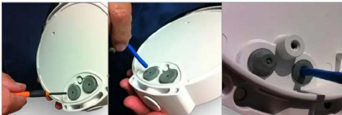
The wire grommets on the back are sealed until perforated by the installer. The integrity of these seals are essential in order to keep moisture from entering the enclosure. Carefully pierce the seals to ensure the integrity of the seal around the cable.
natural_image
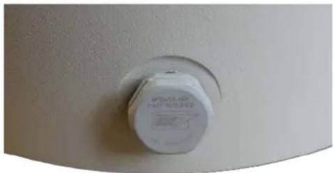
Close-up of a white plastic cap with a hexagonal hole, mounted on a curved surface (no visible text or symbols)Featuring a Gore® vent, the enclosure allows it to breathe without letting in moisture. The vent is fitted in the white hexagonal bolt head on the side of the enclosure. The Gore vent is essential for preventing condensation from forming in the camera.
The Gore vent is relatively fragile. Do not probe or touch the vent unnecessarily.
CAUTION: Do not alter the Gore vent. Altering the Gore vent impacts the cameras performance and moisture may build within the bubble dome.
The camera has an M20 conduit entry on the side. Fit a 20 to 13 mm (.79 to .5-inch) adapter if using an imperial sized conduit. When shipped from the factory the enclosure has an O-ring plug installed in the conduit entry.
Note: If using the conduit connection, the installer must ensure that water or moisture cannot enter the enclosure from the conduit.
The two wire grommets provide for a single cable each that is 5 to 7mm (0.197 - 0.276 in.) diameter. This accommodates most industry standard Ethernet and alarm signal cables.
NOTICE: Only one wire should pass through a cable entry grommet to avoid seal issues. Passing more than one wire through the grommet invalidates the warranty.
-
Puncture the diaphragm of the grommet by using a sharp tool.
-
Pass a round Ethernet cable (CAT5 or better) through a 20 mm compression cable gland. If using the side entry or one of the rear rubber grommets, gently pull the cable back to help secure and seal.
NOTICE: Secure the cable to prevent movement.
- Prepare the wires in accordance with EIA 568B standards for crimping (RJ45 connector not supplied). Use appropriate equipment to crimp the RJ45 Ethernet connector. Outdoor Evolution cameras require feeding the cable through the rear second rubber grommet (supplied).
NOTICE: Secure the cable to prevent movement during and after the installation. Securing the cable may require additional fasteners, not supplied.
natural_image
Three-panel photo showing hands using a tool to adjust or install a white electronic device with green components (no visible text or symbols)3.5.2.2 Mounting
- Attach the Base Assembly to a wall or ceiling surface with the four holes located outside the trim ring seal joint. These holes support #10 hardware and have 25 mm (1 in.) of internal boss to pass-through.
- Use hardware appropriate for the mount surface and which supports a minimum of four times the weight of the camera and assembled enclosure.
- For vandalism, consider different hardware and mounting strategies. The enclosure covers a hole or box in the mounting surface through which you pull the wires.
NOTICE: Drilling holes through the enclosure affects the IP66 rating, the camera sealing properly and invalidates the warranty.
The enclosure allows for routing wires around or over the camera module to the connection points.
-
Remove the alarm connector (if used) from the Camera Module to facilitate connection and service.
-
Attach the Camera Module and route the cables.
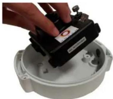
-
Rotate the Camera Module into the mounting clip in the Base Assembly.
-
Fasten the Camera Module in place with the captive thumb screw.
-
Pass the Ethernet cable around the Camera Module; secure the cable by clicking the connector into position.
-
Route wires to avoiding crossing over the lens area when attaching the Trim Cover.
Fitted for factory use only is BNC video connector.
-
Assemble the Trim Cover using the four captive security screws and the provided Security Screw Driver Bit. (See Dome Handling and Cleaning, page 30).
-
For installations using the side conduit entry, remove the sealed plug and a 20mm (.79 in.) conduit connector attaches directly to the enclosure.
natural_image
Hand placing a black sensor device into a white circular housing (no visible text or symbols)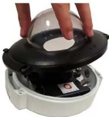
natural_image
Close-up of hands installing a black dome-shaped device with a small circular component inside (no visible text or symbols)NOTICE: When using the conduit connection, you must ensure that water or moisture cannot enter the enclosure through the conduit
3.5.3 Sun Shield
The Sun Shield is recommended whenever there is significant direct light and sun exposure.
The outer surface around the enclosure provides an air gap. The air gap acts as an insulator reducing heat.
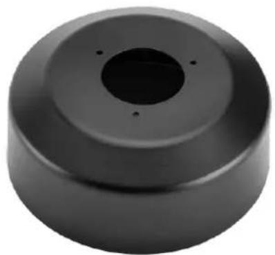
Only use the Sun Shield in pendant mounting configurations (with or without the wall mount).
Attach the Sun Shield to the top of the pendant adapter with the three supplied screws.
natural_image
Circular black mechanical component with a central hole and four small holes (no text or symbols visible)3.6 Stainless Steel Camera – Surface Mount
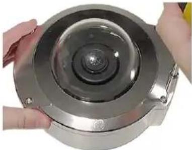
The Evolution Stainless Steel Dome camera is Electropolished marine grade 316 stainless steel. The Stainless Steel camera has the highest rating, at IP-69K, and is the most suitable camera for industrial environments. The Trim Cover and Base Assembly prevents reaching the camera and ensures dust and moisture do not reach inside the enclosure. All mounting perforations are outside the enclosures sealed area.
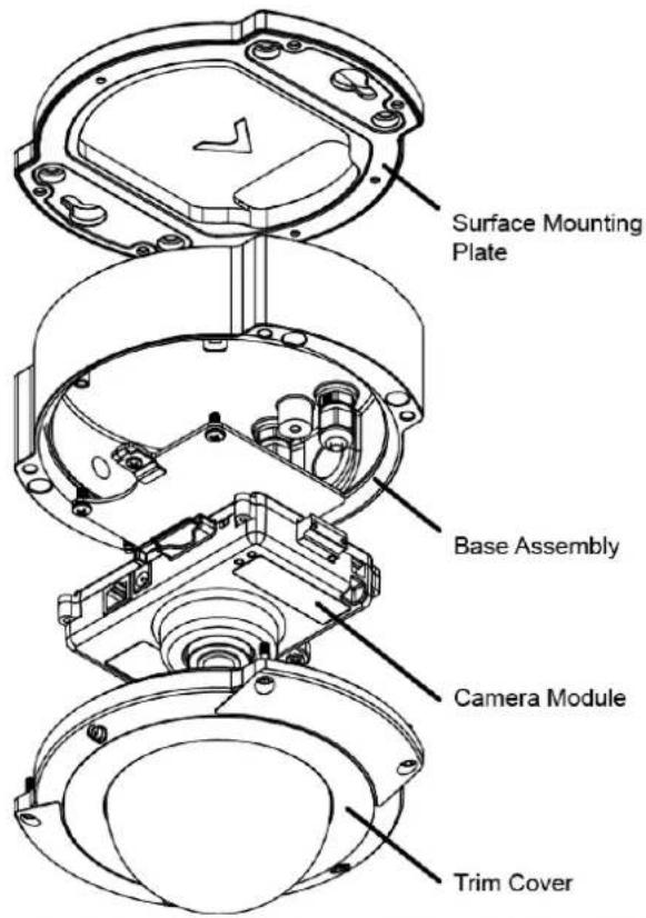
Figure 7 Stainless Steel Camera – Surface Mount Exploded View
3.6.1 Parts Supplied
- Camera Module
• Surface Mounting Plate - Conduit Gland Adapter
-
Quick Start Guide
-
Hex Screwdriver
- Spanner
- Drilling Template
3.6.2 Installation Steps
3.6.2.1 Preparation
- Remove the four cover screws using the Hex screwdriver.
- Carefully remove the dome cover.
- Detach the dome cover from the safety wire and remove the camera module.
3.6.2.2 Mounting
- Using the drilling template, drill-mounting holes for the mounting screws.
- Attach the Surface Mounting Plate with appropriate mounting screws.
- Pass the unterminated network cable through the camera base.
- Align the camera base to the Surface Mounting Plate and twist into place.
- Secure the camera base to the Surface Mounting Plate.
- Pull approximately 25 cm (10 in.) of the network cable through the cable gland.
- Tighten the cable gland using the supplied spanner. Optionally, use the Conduit Gland Adapter to route cable into a conduit (.75-inch NPT).
CAUTION: Ensure all cable entries are sealed to maintain the IP69K rating. - Terminate the network cable and secure the camera module into the camera base.
- Connect the network cable to the camera.
- Reattach the dome cover safety wire.
- Secure the dome cover screws using the Hex screwdriver.
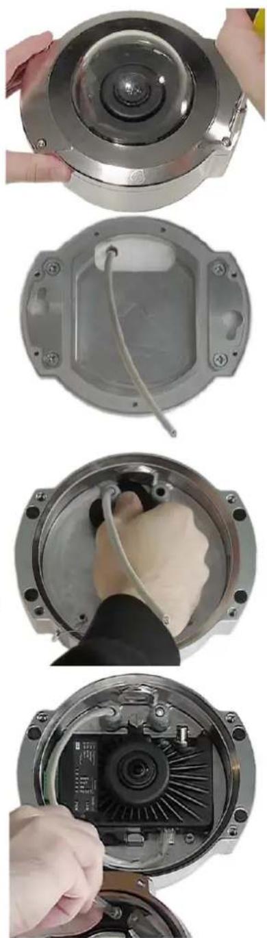
Shown is EVO-12, the EVO-05 installation is identical.
3.7 Stainless Steel Camera – Pendant Mount
The Evolution Stainless Steel Dome camera is Electropolished marine grade 316 stainless steel. The Stainless Steel camera has the highest rating (IP-69K) and is the most suitable camera for industrial environments. The Trim Cover and Base Assembly prevents reaching the camera and ensures dust and moisture do not reach inside the enclosure. All mounting perforations are outside the enclosures sealed area.
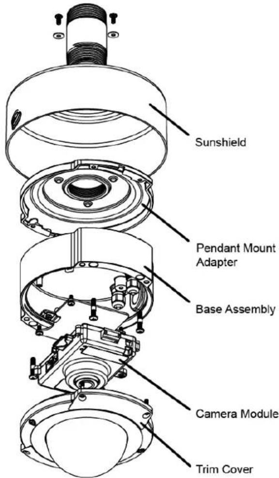
Figure 8 Stainless Steel Camera – Pendant Mount Exploded View
3.7.1 Parts Supplied
- Camera Module
- Pendant Mount Adapter
Sunshield -
Pipe Thread Adapter
-
Quick Start Guide
- Hex Screwdriver
- Spanner
- Drilling Template
3.7.2 Installation Steps
3.7.2.1 Preparation
- Remove the four cover screws using the Hex screwdriver.
natural_image
Close-up of hands holding a metallic mechanical component with a central circular opening (no visible text or symbols)- Carefully remove the dome cover.
- Detach the dome cover from the safety wire and remove the camera module.
- Remove the three pendant mount screws and washers.
- Aligning the holes, secure the Sunshield to the Pendant Mount Adapter using the three screws and washers.
3.7.2.2 Mounting
- Use the pipe thread adapter only when connecting to a female 1.5-inch NPT connection. Attach pipe thread adapter to the pendant bracket (not supplied).
- Attach the Sunshield and Pendant Mount assembly to the pipe thread adapter.
- Align the camera base to the Pendant Mount assembly and twist into place.
- Secure the camera base to the Pendant Mount assembly.
- Pull approximately 25 cm (10 in.) of the network cable through the cable gland.
- Tighten the cable gland using the supplied spanner. Ensure the second cable gland is blocked off if unused.
CAUTION: Ensure all cable entries are sealed to maintain the IP69K rating.
-
Terminate the network cable and secure the camera module into the camera base.
-
Connect the network cable to the camera.
-
Reattach the dome cover safety wire.
-
Carefully secure the dome cover screws using the Hex screwdriver.
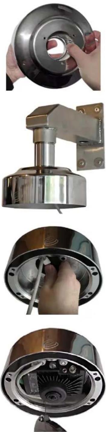
Shown is EVO-12, the EVO-05 installation is identical.
4 Camera Mounts
The following mounting accessories are available for the Indoor and Outdoor Evolution cameras to allow installation in multiple environments.
Indoor installations may require a Pendant Mount in addition to the Wall Mount kit. Connecting to 1.5-inch NPT female pipe threads requires a Gender adapter. Outdoor Pendant Mounts do not require the Gender adapter. Use all Corner, Pole and Wall Mount Brackets with the Evolution Pendant Mount. See Pendant Mount, page 28 for details.
4.1 Wall Mount
The Wall Mount has a 1.5-inch NPT female pipe thread, allowing the Pendant Mount to fasten. There is a set screw in the 1.5-inch thread area which locks the housing into a fixed rotation.
OBE-04-OWA -White
OBE-04-OBA - Black
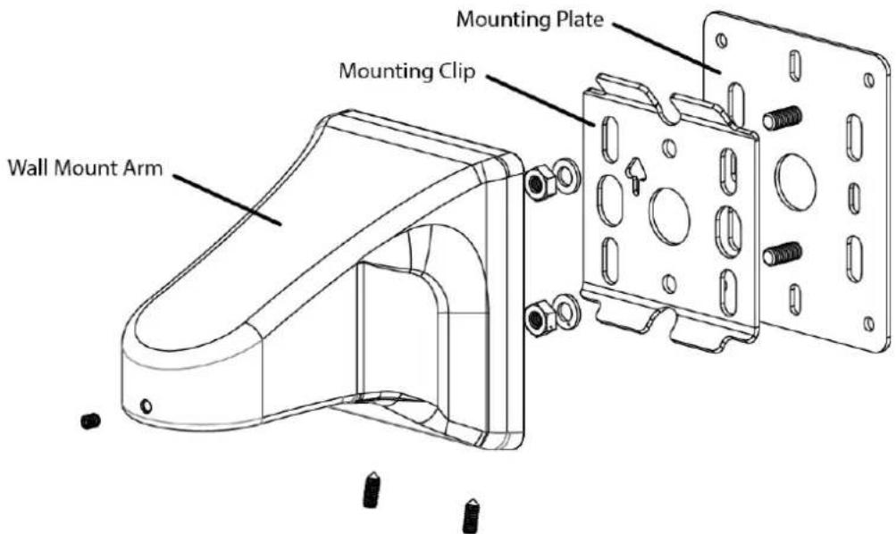
Figure 9 Wall Mount Exploded View
The Mounting Plate is not required when mounting to a studded or solid wall where you are not using an electrical box.
Likewise, do not use the Mounting Plate for Pole or Corner Mount installations.
- Fasten the Mounting Clip to the wall surface using fasteners (not supplied). Ensure using the appropriate fasteners for the wall material (capable of supporting a minimum four times the weight of the wall mount and camera).
- Ensure that the arrow mark on the plate is oriented up.
- Pass the cables through one of the holes in the plate.
- Hook the wall mount arm over the top tabs on the Mounting Clip.
- Tighten the two set screws on the bottom, locking the arm to the Mounting Clip.
- Pass the cables through the mount arm and out the threaded hole on the end of the arm.
4.1.1 Rough Surfaces or over Electrical Boxes
- Fasten the Wall Mount Plate to the box or the wall surface.
- Fasten the Mounting Clip using the two nuts and washers provided.
This provides an even surface for the Mounting Clip Plate.
CAUTION: Do not mount the camera to an electrical box where the camera would be easily accessible. Ensure the electrical box is structurally sound to support the camera.
4.2 Corner Mount
The Corner Mount is a bracket that adapts the wall mount to fit diagonally on the corner of a building, giving a 270° FoV at the corner. Attach to the building through four appropriate fixings (not provided). The bracket has an opening that accommodates a conduit connection into the back of the wall mount. The Wall Mount Mounting Clip attaches directly to the Corner Mount bracket in the same manner as the pole mount.
OBE-05-OWA - White
OBE-05-OBA - Black
Use with the Wall Mount kit sold separately.
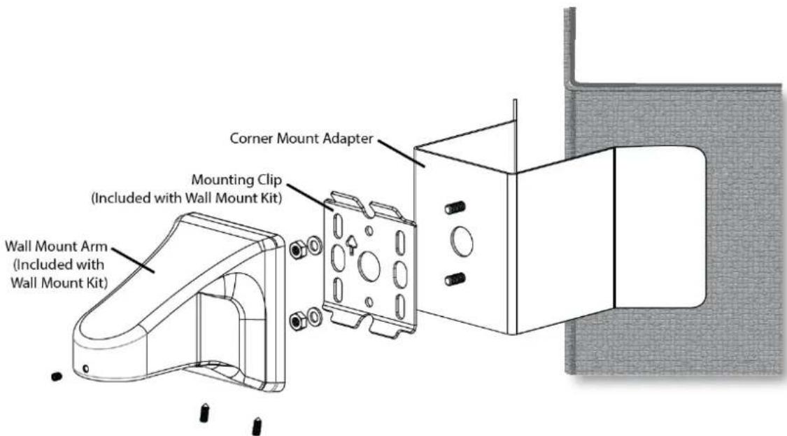
Figure 10 Corner Mount Exploded View
-
Fasten the Corner Mount Adapter to wall surfaces using four fasteners (not supplied). Ensure the fasteners are appropriate for the wall material and capable of supporting at least four times the weight of the wall mount and camera.
-
Fasten the Wall Mounting Clip to the Corner Mount adapter using the two nuts and washers provided with the Wall Mount Kit.
Note: The Wall Mount Plate is not used.
- If necessary, the hole in the Corner Mount Adapter accepts a flexible conduit adapter.
- Pass the cables through the hole and into the Wall Mount Arm.
- Fasten to the Mounting Clip.
4.3 Pole Mount
Use the Wall Mount Kit in conjunction with the Pole Mount when attaching to a light pole. In addition, use the Pole Mount and Corner Mount to connect to the corner of a building. The Pole mount is a bracket that attaches to a pole 100 to 150 mm (4 to 6 in.) in diameter with the provided stainless steel clamping bands.
The Pole Mount Adapter has a hole that accommodates a conduit connection from the Wall Mount Arm if it is necessary to protect the wires from the environment. The Mounting Clip attaches directly to the Pole Mount Adapter in the same manner as the Mounting Plate.
OBE-03-OWA - White
OBE-03-OBA - Black
Use with the Wall Mount kit sold separately.
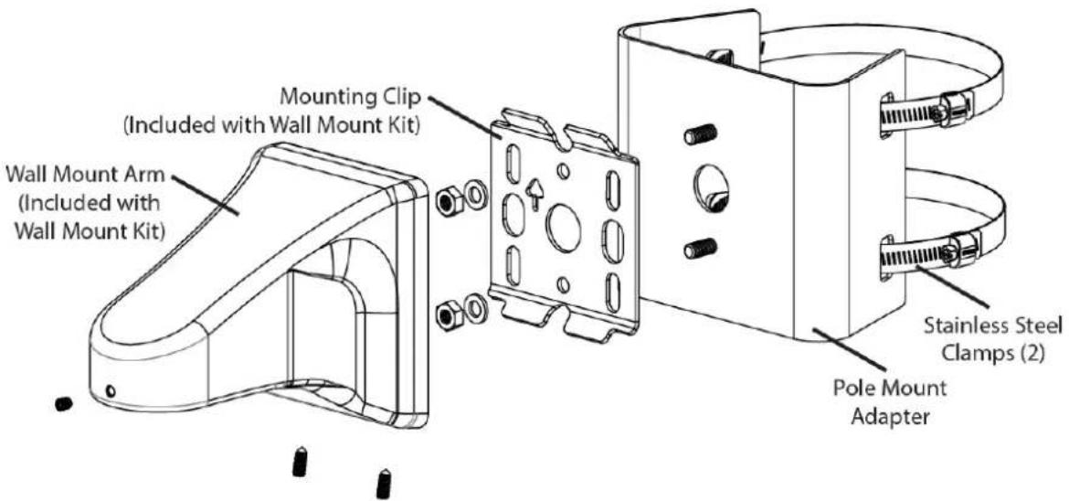
Figure 11 Pole Mount Exploded View
- Fasten the Pole Mount Adapter to the pole using the two Stainless Steel Clamps.
- Fasten the Mounting Clip to the Pole Mount Adapter using the two nuts and washers provided with the Wall Mount kit.
Note: The Wall Mount Plate is not used.
The hole in the Pole Mount Adapter is designed to accept a flexible conduit if desired.
-
Pass through the cables into the hole and the Wall Mount Arm
-
Fastened the Wall Mount Arm to the Mounting Clip.
4.4 Pendant Mount
For mounting an enclosure below the ceiling, use the accessory Pendant mount for 1.5-inch NPT pipe threads.
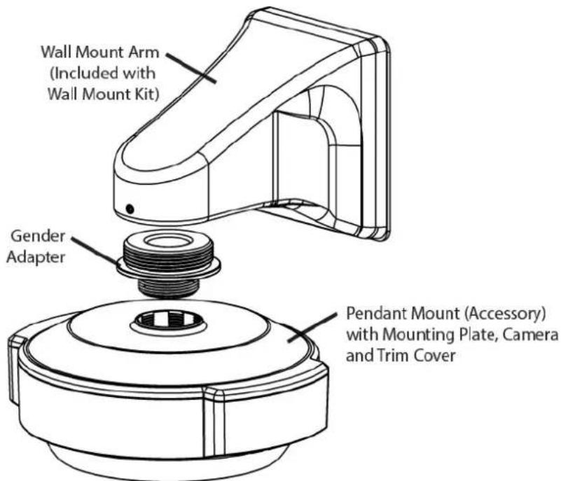
Figure 12 Pendant Mount Exploded View The Wall Mount kit is sold separately.
| Indoor Housing | ||
| Pendant Mount | OBE-01-IWA | White |
| OBE-01-IBA | Black | |
| Gender Adapter | OXM-03-UWA | - |
| Outdoor Housing | ||
| Pendant Mount | OBE-01-OWA | White |
| OBE-01-OBA | Black | |
The Indoor Evolution camera housing requires the use of the Pendant Mount and Gender Adapter (sold separately). When using the Wall Mount indoors, directly mount to the 1.5-inch NPT threaded pipe.
- Thread the indoor Pendant Mount to the Gender Adapter.
- Attach Pendant and Gender adapter assembly onto the Wall Mount Arm.
- Run the cable through the Wall Mount Arm and Mounting Plate.
- Attach the Mounting Plate.
- Rotate and tighten the set screw locking the camera into the desired orientation.
- Attach the cable to the Mounting Plate using the two snap features in the Pendant Mount.
- Fasten the Mounting Plate to the Pendant Mount using the two Plastite® thread forming screws into the two bosses with the cables passing through.
The Outdoor Evolution camera housing requires the use of a Pendant Mount (sold separately) to fit the housing to the Wall Mount.
The pendant adapts the enclosure to 1.5-inch NPT female pipe threads. The Pendant Mount has a male thread, therefore if the installation is the length of a pipe use a female-to-female coupler.
- Use Teflon® or PTFE pipe tape on pipe threads to allow compliance, sealing and alignment.
- Pass cabling through the Pendant Mount.
- Mount the Pendant Mount to the pipe.
- Thread cabling onto the Wall Mount Arm.
- Rotate and tighten the set screw to lock the camera into the desired orientation.
- Mount the Outdoor Base Assembly to the Pendant Mount with the cables passing through the IP66 grommets in the back of the assembly.
- Mount the Base Assembly to the Pendant Mount with the supplied four 1" fasteners.
5 Test
- Confirm the Camera module is installed correctly.
- Confirm the thumb screw is fastened to prevent movement.
- Connect the Ethernet cable (RJ45) to the camera module.
- Connect the alarm input / output / alarm reset cable and the remote microphone (if necessary) to the camera module.
- Apply power to the camera. The camera module LEDs light starting with the quick green, red and then green LED.
NOTICE: Without PoE power use only a UL/CSA-approved LPS or NEC Class 2 power source with a 12 VDC 1 Amp AC adapter (not supplied). This alternate power source must have a wired plug connector with the correct polarity (+ve center).
The camera's focus is factory set and locked.
5.1 Indoor Camera
- Align the dome trim ring over the base plate ensuring the retaining clips align correctly and allowing the trim ring to clip into place.
- Refit the trim ring screw with the supplied Torx driver.
- Remove the screen protection film from the dome.
5.2 Outdoor Camera
- Carefully re-seat the dome trim ring.
Note: Ensure the dome surface is not damaged and the dome seal is retained. - Refit the dome screws with the supplied Torx driver. Tighten the dome screws ensuring ingress protection is maintained around the dome seal.
- Remove the screen protection film from the dome.
- Carefully polish the dome surface with a soft, lint-free, nonabrasive cloth to complete the installation. Contaminants left on the dome or lens degrade optical performance, causing poor focus, incorrect color balance, lens flare and other undesirable effects.
6 Dome Handling and Cleaning
The standard dome is made of a polycarbonate (PC) polymer. Take care when handling or cleaning a dome to avoid scratching the surface.
• Always handle the dome by the outside edge of the flange or trim ring assembly.
- Avoid contacting inside surface of the dome.
- Remove dust or other surface contaminants from the dome's interior with clean, dry air pressure (compressed air cans).
- Remove heavy residue (spots, streaks, stains) or other contaminants from the dome surface with a solution of a mild liquid dish detergent or isopropyl alcohol and water. Only use lint free soft paper towels or a microfiber cloth. After cleaning the dome, apply clean, dry air to complete drying and leave no dust.
- Scratches or other surface blemishes within the material of the dome may be removed by applying a non-abrasive wax (Meguiar's #18 or equivalent) with a microfiber cloth. After waxing, apply clean, dry air to complete drying and leave no dust.
NOTICE: The dome may become unusable due to excessive pressure or rubbing causing permanent scratches.
7 First Time Operation
The factory default configuration is DHCP. In order to use the camera you need the IP address. When a DHCP server is unavailable, the factory default IP address is 192.168.0.200.
Install the Oncam Grandeye IP Configuration Tool. Find the latest version at www.oncamgrandeye.com. Configure all camera IP addresses with the IP Configuration Tool.
7.1 DHCP
DHCP is the default camera configuration. Cameras acquire a unique IP address when connected to a network with a DHCP server. If you are using DHCP permanently for the camera's IP address, be sure to reserve that address with the DHCP server to ensure that the assigned IP address does not change. If a DHCP server is not found or DHCP is disabled, the camera will revert to its current static IP address.
7.2 Static IP Installation
The factory default IP address is 192.168.0.200.
For a multi-camera installation, always introduce the cameras one at a time and then re-address them to a non-conflicting static IP address. Use the Network Settings page in the Camera Web Interface or the IP Configuration Tool.
7.3 Finding Available Cameras
Use the Oncam IP Configuration Tool to discover cameras installed on your Local Area Network (LAN).
- Open and run the configuration tool.
- Select the camera type to see a list of installed cameras on your network.
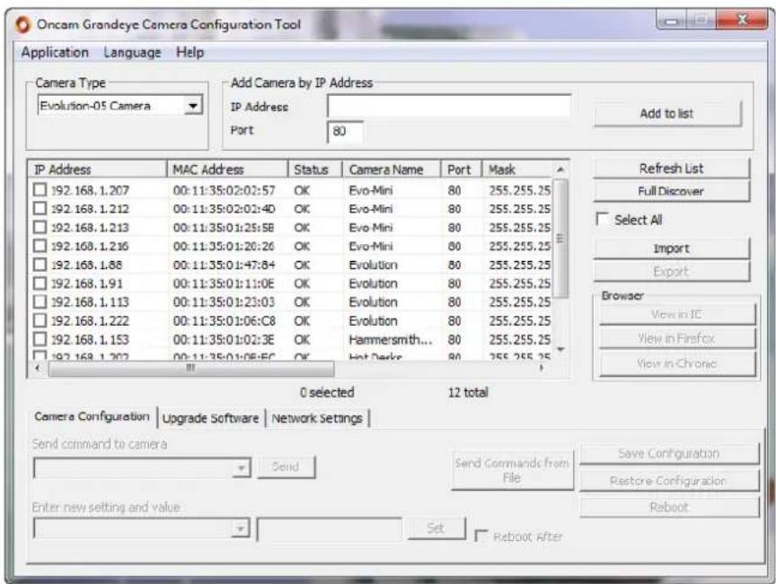
Figure 13 Oncam Grandeye Camera Configuration Tool
7.4 Assigning an IP Address
- Select the Camera Type.
- Press Refresh List or Full Discover to find new cameras, or update information on cameras already in the list.
- Check the IP Address box for changing the IP address of a camera.
- Select the Network Settings tab.
- Click Get Network Settings to download current settings.
- Click OK once the download completes.
- Enter the new IP address, Subnet Mask and Gateway and disable DHCP.
- Click Save Network Settings to upload new settings to the camera.
You can identify cameras by their MAC addresses. Find the MAC address printed on the camera label and packaging.
7.5 Connecting to the Camera
Connect to any camera on your network by entering the camera IP address into the address bar of a browser running on a PC on the same network. To access the Web interface, open a browser window (Internet Explorer, Edge, Safari or Firefox) and enter the IP address of the camera. (For example, http://192.168.0.200).
The first response will be an authentication screen requesting a User Name and Password:
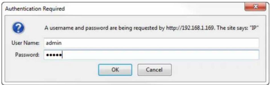
Default User name: admin
Default Password: admin (case sensitive)
Note: The admin user is permanent and cannot be renamed or deleted.
For security purposes, you should change the admin password. If desired, add other users and set the admin password to a complicated random string. Then use another user name for routine maintenance.
7.6 Media Player Requirements
QuickTime or VLC media player are required for viewing video through a web browser. The web browsers supported are Internet Explorer, Edge, Safari or Firefox.
7.6.1 QuickTime
For firmware versions earlier than 1.9.9.243, use QuickTime version 7.7.4.
Download the QuickTime media player from https://software.com/windows/video/apple-quicktime/7.7.4.
7.6.2 VLC
For firmware versions later than 1.9.11.310, use the latest VLC media player.
Download the latest VLC media player from www.videolan.org > VLC > Download.
8 Camera Web Interface
Access camera configuration through the camera Web interface.
- Open a browser window and enter the camera IP address.
- Enter the User name and Password for this camera. The Control Panel screen displays.
Note: Images in the following sections may vary.
8.1 Control Panel
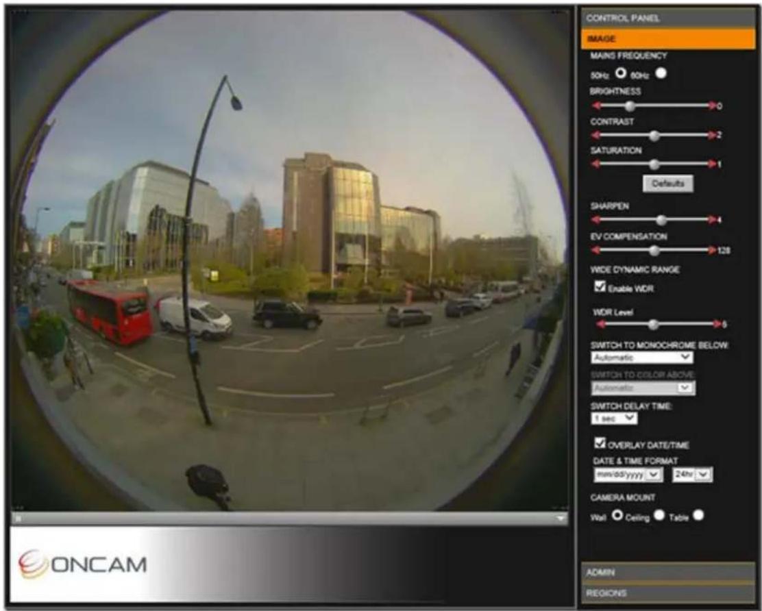
The camera produces a fisheye view that is a full 360-degree image in a circular format. The camera streams two fisheye images at the same time.
By default, only Fisheye1 displays in the Control Panel with one of the following options.
| 4 MP | 2144 x 1944 |
| 2 MP | 1448 x 1360 |
| 1 MP | 1056 x 960 |
| 0.25 MP | 528 x 480 |
Set the resolution from Admin > Stream Settings. See Stream, page 44.

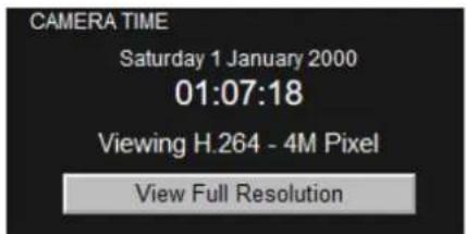
Shown in the right pane is the Control Panel that includes the camera date and time, and current image streaming.
Set the current date and time from the Admin tab.
8.2 Image
The Image tab includes lighting and orientation controls for the image sensor.
Mains Frequency
Select the mains frequency depending based on the camera location.
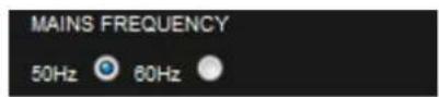
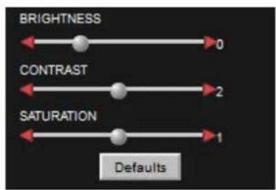
Image Controls
Adjust the view using the image controls (Brightness / Contrast / Saturation).
Select the Defaults button to return the sliders to their default settings.
The camera has automatic imaging controls to guarantee the best image quality at all times.
Rarely use manual tuning.
flowchart
graph TD
    A["BRIGHTNESS"] --> B["0"]
    C["CONTRAST"] --> D["2"]
    E["SATURATION"] --> F["1"]
    G["Defaults"] --> H["End"]
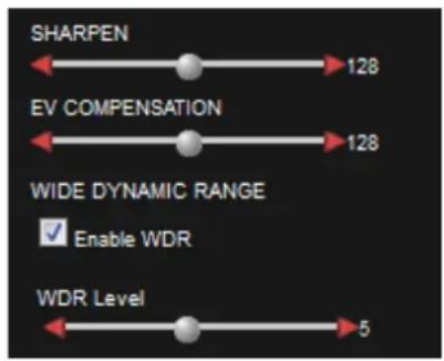
8.2.1 Sharpen
Increase or decrease the clarity and focus of an image. Using the Sharpen setting also emphasizes noise and increases data size.
8.2.2 EV Compensation
Increase or decrease the image exposure. Adjust the EV Compensation for unusual lighting conditions.
8.2.3 Wide Dynamic Range
Wide Dynamic Range. This increases the dynamic range in difficult lighting conditions. WDR particularly lightens dark areas without over brightening light areas.
WDR Level. After enabling WDR adjust the amount of WDR processing that is applied to the image. Higher settings further bring-out detail in shaded areas, in exchange for slightly lowering the overall contrast.
8.2.4 Switch to Monochrome
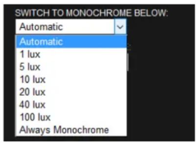
Control how the camera image switches from Color to Monochrome in response to different illumination levels.
Selecting Automatic (default) and the camera transitions progressively between color and monochrome as the illumination level varies.
Selecting Always Monochrome and the camera image remains in monochrome at all times.
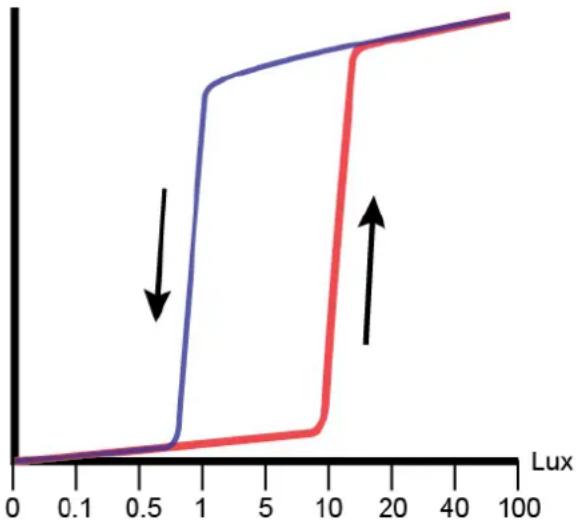
Selecting specific Lux thresholds separates settings made for the Color-to-Monochrome to help the color remain stable in varying low-light conditions. In this configuration, the color follows a hysteresis curve as illustrated in Figure 14 Color Hysteresis Curve.
line
| Lux | Blue Line Value | Red Line Value | |-----|-----------------|----------------| | 0 | 0 | 0 | | 0.5 | 0 | 0 | | 1 | 1 | 0 | | 5 | 1 | 0 | | 10 | 1 | 1 | | 20 | 1 | 1 | | 40 | 1 | 1 | | 100 | 1 | 1 |Figure 14 Color Hysteresis Curve
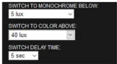
In Figure 14 Color Hysteresis Curve, the camera switches to Monochrome when the illumination falls to 1 Lux. The camera switches back to Color mode when the Lux rises to 20 Lux.
Set the two settings differently so the camera does not oscillate between color and monochrome when the illumination level is close to the threshold.
- Non-Permanent IR Light. Set the Monochrome-to-Color threshold high enough that the camera does not switch back to color mode when the IR lighting is present.
- Lux Readings. A lux meter reading may differ from a 360° sensor due to differing fields of view.
- IR-Sensitive Camera. Lux meter readings may differ because the camera accepts IR light.
8.2.5 Switch Delay Time
Select a delay time to prevent unwanted switching with large temporary light changes (for example, car headlights). Ignored are variations in illumination shorter than the defined Switch Delay Time.
The camera will not switch to Color mode if the illumination changes from 3 Lux to 100 Lux for 3 seconds and then falls back to 5 Lux.
8.2.6 Image Time and Date Overlay
Overlay the current date and time onto the image outside of the fisheye circle so not obscuring the video. The scaled image and overlay appears small when viewed using a web browser. Settings are available to set the format of the date and time text.
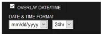
8.2.7 Camera Mount
Camera mount position. Mount cameras vertically or horizontally (for instance, wall or ceiling). When using the Oncam SDK for camera viewing and recording this setting ensures the scene is properly de-warped and the NVR PTZ operations correctly work. Set PTZ to match the installation position of your camera.
8.3 Administration
The Admin menu provides the camera software version and MAC address. Access all administrative camera parameters through the Admin menu.
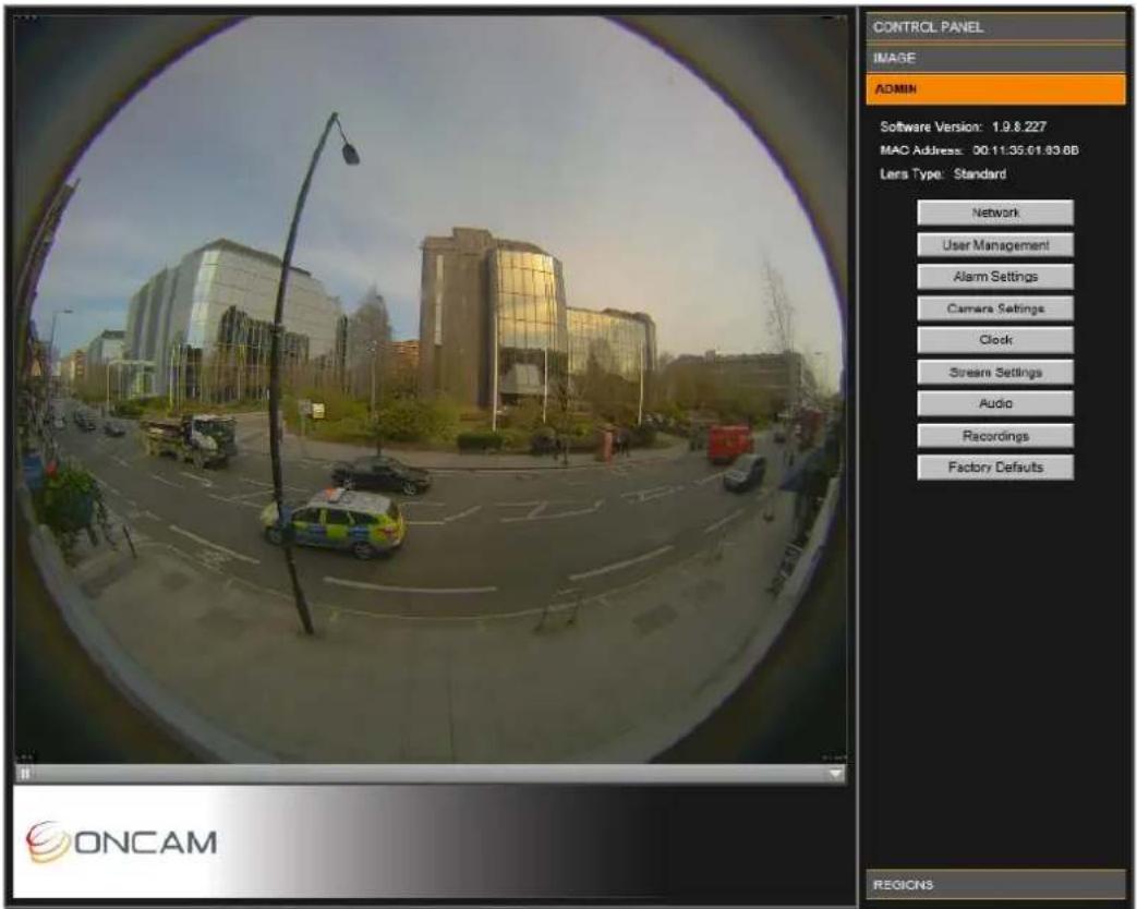
Figure 15 Administration Settings
8.3.1 Network
Using the Camera Configuration Tool you can configure the different Network Settings.
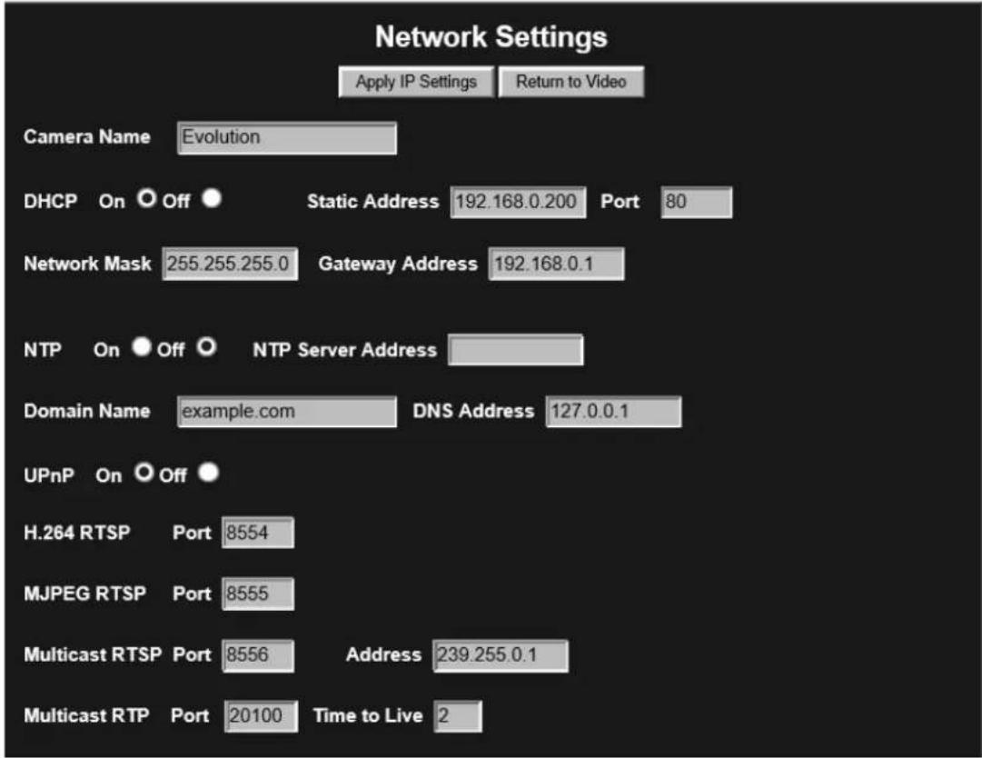
Figure 16 Network Settings
DHCP (Default). The camera is configured for DHCP. Detect the camera using the Camera Configuration Tool.
Static IP Address. Configure the camera using the Static IP address if DHCP is unavailable.
Camera Name. Modify the Camera Name.
Default port. Connecting the web server defaults to port 80.
NTP Server. Provides accurate time services to the camera. For a Network Time Protocol server, enter the DNS name or IP address of the NTP Server.
UPnP (On / Off). Enable the Universal Plug-and-Play feature to show the camera from other UPnP compatible devices on the same network (for example Windows computers).
Multicast RTSP port. Use the RTSP port for receiving a multicast RTSP request from a client.
Multicast RTP port. Use the RTP port for multicasting the video. The clients that receive the video use the Multicast RTP port and Address value to receive the video. Consult your network administrator.
Address. Use the IP address for multicasting the video. The clients that receive the video will use the Address value as well as the Multicast RTP port value to receive the video. Consult your network.
Time to Live. Sets the Time to Live value in your multicast IP packets. Consult your network.
NOTICE: If making changes, click Apply IP Settings to save changes. Your Web Interface connection may be lost if the IP address changes to another subnet.
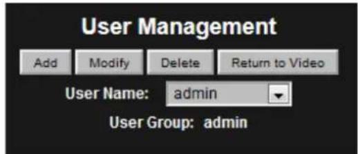
8.3.2 User Management
Enter a User Name and Password for each user. There are three different user profiles.
User
View image streams and camera configuration.
Operator
Change image and IP, motion regions, alarm settings and administer a factory reset.
Administrator
Access all functions, including user configuration.
8.3.3 Alarms
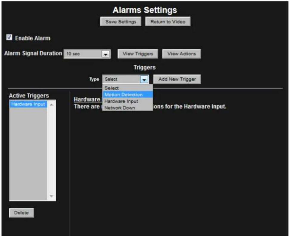
Figure 17 Alarm Settings Triggers
Alarm Signal Duration. The length of time that an alarm persists after the alarm is triggered.
View Triggers. Access a list of triggers that activate an alarm by selecting the View Triggers button. As necessary, configure the active Triggers list.
Add New Trigger. Select a trigger type from the drop down list and his button select the Add New Trigger button to add another trigger to the Active Triggers list.
Available triggers include the following.
- Motion Detection – Movement detected in a defined region
- Hardware Input – A sensor or button attached to hardware I/O interface
• Network Down – The camera has lost its network connection
Use the Delete button to delete an unwanted trigger.
View Actions. Select the View Actions button. Configure the active actions list after setting the active triggers. Complete these actions when any trigger has activated. You cannot set Triggers to individual specific Actions.
Available actions include the following.
- Hardware output – A hardware device attached to the hardware I/O is activated.
- Record to SD Card – Video is recorded to the SD Card for a period of time
- Send E-mail – Send a notifying e-mail
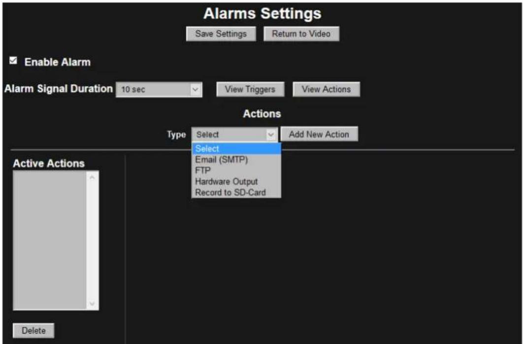
Figure 18 Alarm Settings Actions
Some actions have configurable options. From the Active Actions list, select the action to configure.
Email (SMTP). Send an email in response to an alarm by configuring Email (SMTP).
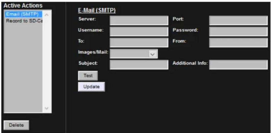
Figure 19 Alarm Settings Actions – E-Mail
FTP. Images sent to an FTP server.
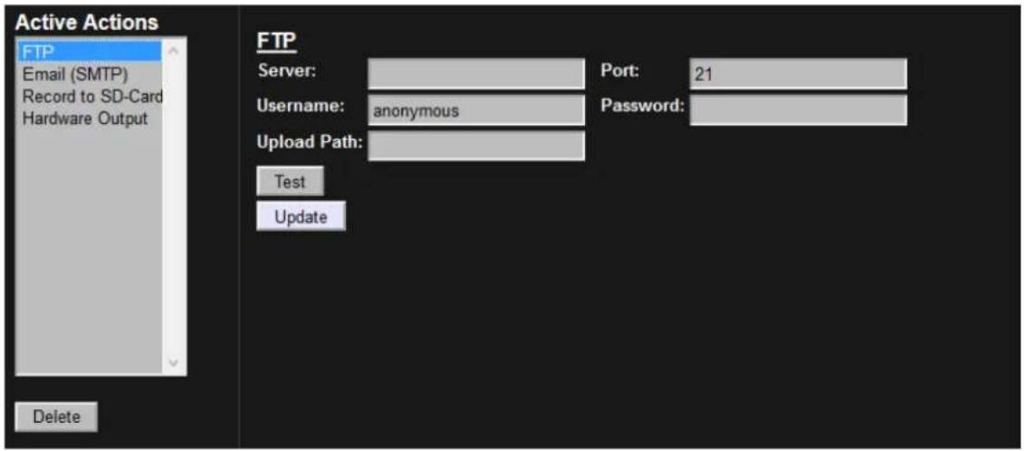
Figure 20 Alarm Settings Actions – FTP
Record to SD-Card. Setup an alarm for recording to the SD-Card.
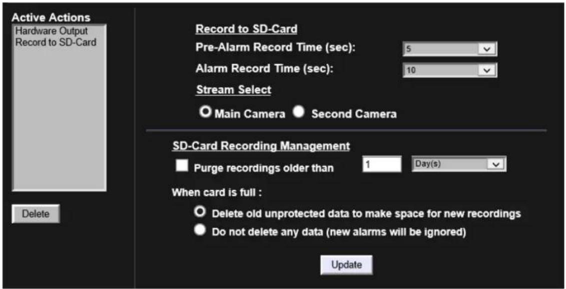
Figure 21 Alarm Settings Actions – Record to SD-Card
The entire recording duration is the sum of the pre-alarm and alarm times.
You can record from either the Main Camera or the Second Camera streams. The video recording has the same resolution as the live stream.
Use the Delete button to delete an action.
8.3.4 Camera
Set parameters for each individual camera resolution and stream combination. The MJPEG parameters are default when selecting the Camera Stream.
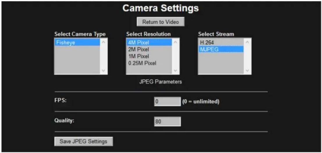
Figure 22 Camera Settings – MJPEG
When selecting the H.264 stream, choose from Rate Control, Bit Rate and GOP Length.
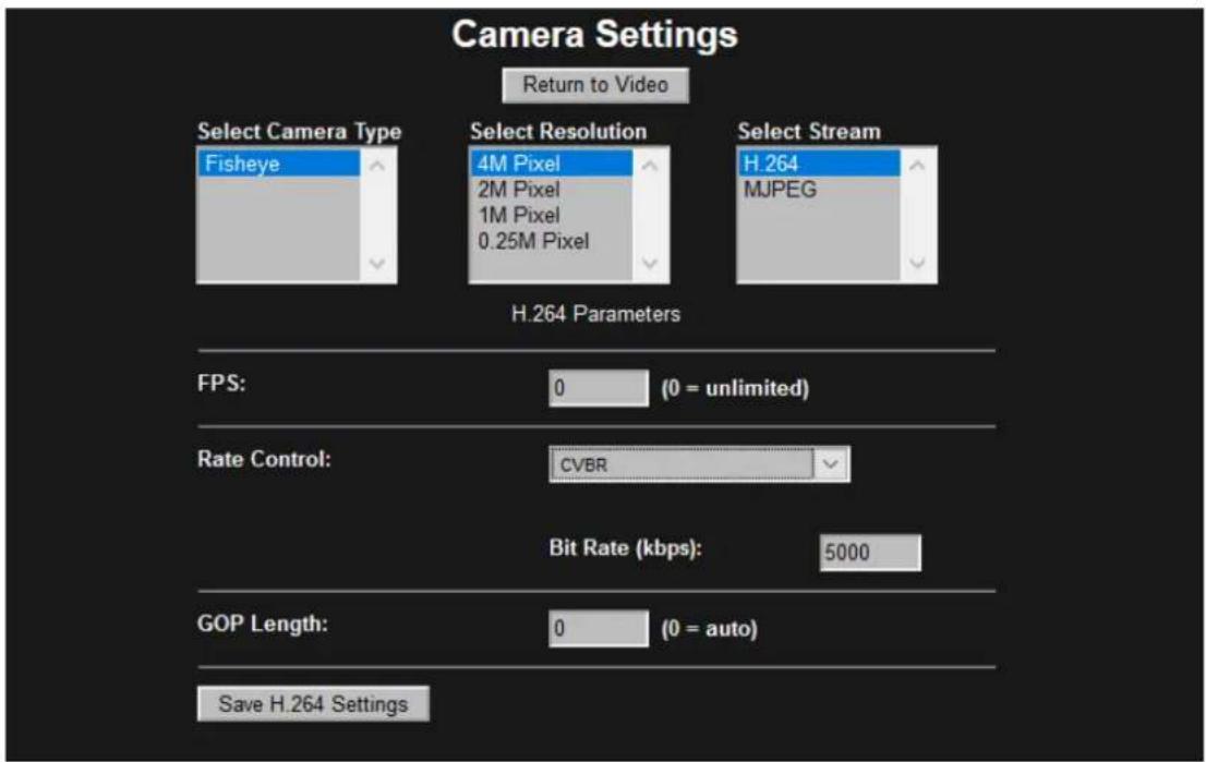
Figure 23 Camera Settings – H.264
8.3.5 Clock
Enter the Region and Zone and set the Camera Time Zone. Then enter the current date and time using 24-hour time format. You can update the camera time directly from the PC or from the Clock Settings.
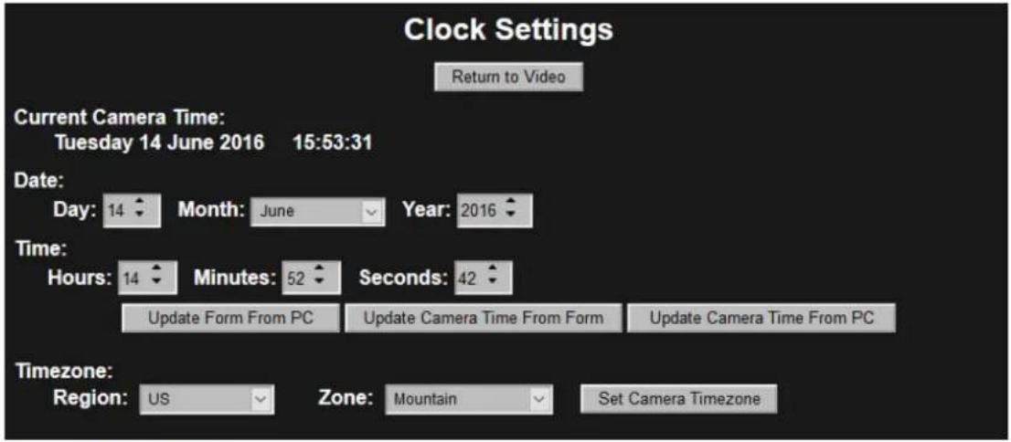
Figure 24 Clock Settings
8.3.6 Stream
Configure either one or two camera streams.
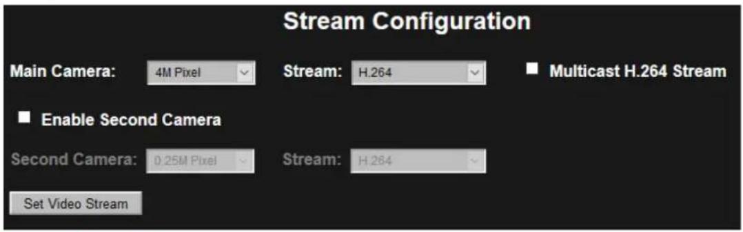
Figure 25 Stream Settings
Resolution. Set the Main Camera or optional Second Camera's resolution.
Stream. Set the stream to either H.264 or MJPEG.
When enabling the Second Camera, the Main and Second camera cannot have the same settings. The maximum frame rate for each stream is reduced with both the Main and Second camera enabled.
Multicast H.264 Stream. Selecting this checkbox multicasts the main video stream according to Network Settings Multicast settings.
Table 1 Main Camera Stream Maximum Frame Rates
| H.264 | MJPEG | ||||||
| 4M | 2M | 1M | 0.25M | 4M | 2M | 1M | 0.25M |
| 10 FPS | 15 FPS | 30 FPS | 30 FPS | 10 FPS | 15 FPS | 30 FPS | 30 FPS |
Table 2 Main and Second Camera Maximum Frame Rates
| Main Stream (stream 1) | ||||||||||
| H.264 MJPEG | ||||||||||
| 4M | 2M | 1M | 0.25M | 4M | 2M | 1M | 0.25M | |||
| Second Camera (stream 2) | H.264 | 4M | N/A | 6 FPS | 9 FPS | 10 FPS | 7 FPS | 6 FPS | 9 FPS | 10 FPS |
| 2M | 6 FPS | N/A | 10 FPS | 15 FPS | 6 FPS | 13 FPS | 10 FPS | 15 FPS | ||
| 1M | 9 FPS | 10 FPS | N/A | 25 FPS | 9 FPS | 10 FPS | 11 FPS | 21 FPS | ||
| 0.25M | 10 FPS | 15 FPS | 25 FPS | N/A | 10 FPS | 15 FPS | 16 FPS | 25 FPS | ||
| 4M | 7 FPS | 6 FPS | 9 FPS | 10 FPS | N/A | N/A | N/A | N/A | ||
| 2M | 6 FPS | 13 FPS | 10 FPS | 15 FPS | N/A | N/A | N/A | N/A | ||
| 1M | 9 FPS | 10 FPS | 15 FPS | 25 FPS | N/A | N/A | N/A | N/A | ||
| 0.25M | 10 FPS | 15 FPS | 25 FPS | 25 FPS | N/A | N/A | N/A | N/A | ||
The figures in Table 2 Main and Second Camera Maximum Frame Rates, page 44 have the mains frequency option set to 50Hz. When the mains frequency is set to 50 Hz, the frame rate is limited to 25 FPS to stop video flickering due to fluorescent lighting. When the mains frequency is set to 60 Hz, the frame rate is limited to 30 FPS. At 60 Hz the 25 FPS entries may achieve a higher frame rate.
8.3.7 Audio
The Audio button accesses Audio configuration.
Using an electret microphone, enable Audio and set the Audio Input Gain to the desired level. The audio is included in any H.264 or MJPEG RTSP camera stream.
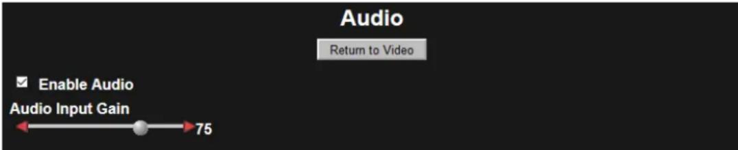
Figure 26 Audio Dialog
Note: RTSP streaming occurs when the stream request a URL using the rtsp:// prefix. Video is not available over RTSP for a 4 MP MJPEG video stream. Only stream HTTP with MJPEG video of this size. The HTTP streaming method does not include audio.
When making an RTSP connection to the audio enabled camera and viewing video an additional mono audio channel streams to the player. The audio uses the G.711 mu-law codec. The audio operates with both H.264 and MJPEG video streams.
8.3.8 Recordings
The Recordings dialog provides information and configuration options for the SD card.
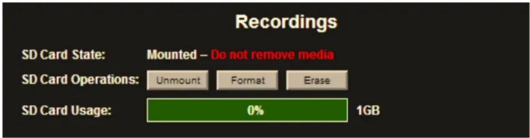
Figure 27 Recordings Dialog
SD Card State. Empty slot / Mounted / Unmounted
NOTICE: Avoid corrupting the SD Card by Unmounting the card prior to removal. Do not remove the SD Card when the SD Card State is Mounted.
SD Card Operations
- Mount / Unmount. Toggle between Mount and Unmount after inserting the SD Card or prior to removing the SD Card.
- Format. Use Format for formatting or reformatting the SD Card. Formatting the SD card erases all data.
- Erase. Click Erase to erase all content from the SD Card.
SD Card Usage. Shows the space remaining in the SD card.
8.3.9 Factory Defaults
Achieve a factory reset through the camera's recessed reset button, the Web Interface, or from the Configuration Tool.
Recessed Hardware. Using the external recessed reset button on the side of the camera module by using a ballpoint pen.
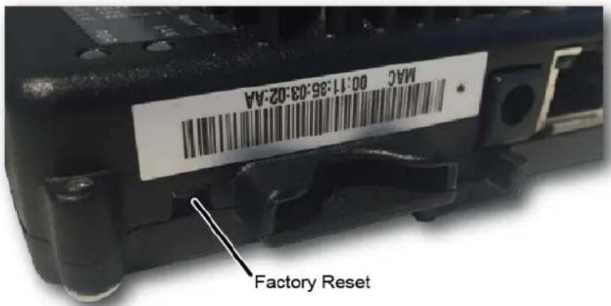
- With the camera powered, press and hold the Factory Default reset button for 30 seconds.
- When the camera restarts, all camera settings are reset to factory defaults.
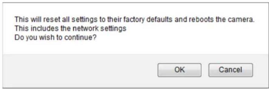
Web Interface. Through the camera's Web Interface Admin pane, click the Factory Defaults button. The following warning message displays before the Factory Default reset continues.
Configuration Tool. Reset to factory defaults through the Camera Configuration tool.
Through the camera configuration tool, check the camera(s) that require a factory reset.
- From Camera Configuration tab
- Select factoryreset.cgi from the Send command to camera field drop-down menu
- Click Send.
- Click Reboot. The camera resets back to factory defaults only after the camera has rebooted.
A message appears after the Reboot action.
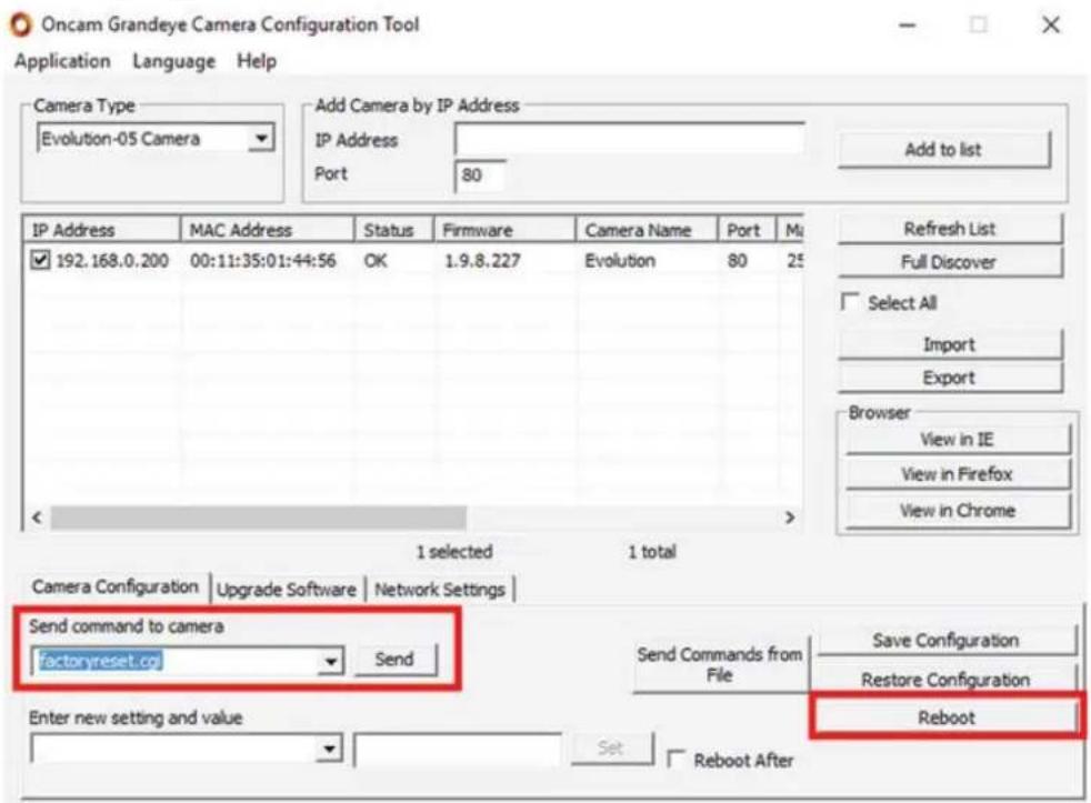
Figure 28 Camera Configuration Tool – Reset to Factory Defaults
Reinstated are the following Factory Defaults.
| DHCP | Enabled |
| Static address | 192.168.0.200 |
| Privacy Regions | None |
| Motion Regions | Enabled |
| Alarm Settings | Enabled |
| Image Settings | Default values |
| User Name | admin |
| User Password | admin (case sensitive) |
NOTICE: Your Web Interface connection is lost if changing to another subnet.
8.4 Regions
Regions are user-defined zones in the image used to analyze an event, trigger an action, or add security that covers part of the image.
Set-up and configure two types of regions
- Privacy regions (up to 10)
• Motion Detection regions (up to 8)
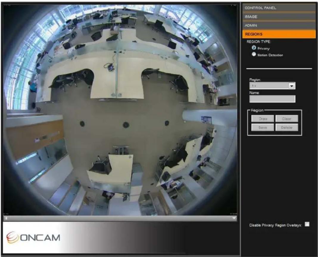
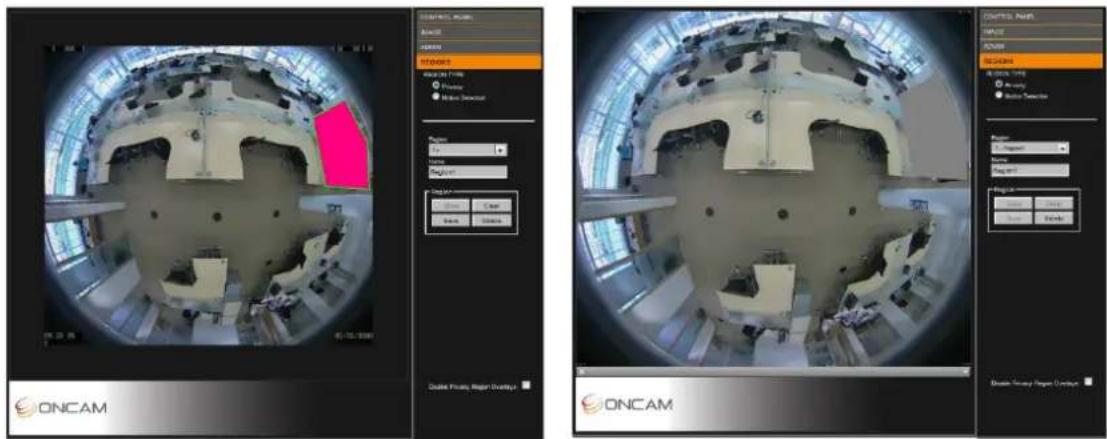
Figure 29 Region Settings
8.4.1 Privacy
Define a Privacy region using a video-embedded mask restricting the viewing of the video streams masked image portion.
- Select a Region number (1 to 10).
- Enter the region Name.
-
Click Draw (the image freezes while you are drawing the zone).
-
Click to set your initial point and continue clicking each point of the defined area until completing the area. Click Clear to restart drawing the shape.
-
Click Save to store the new region to the Region dropdown list.
-
Repeat as necessary for up to 10 regions.
Notes:
- Privacy Regions are automatically enabled when created. Disable them by checking the Disable Privacy Regions Overlay checkbox.

- Delete a region by selecting the region in the list and click Delete. This also deletes any saved name and returns the specific region number to default settings.
8.4.2 Motion Detection
A motion detection region is a user-defined zone for detecting motion and triggering an action such as recording for later analysis. Motion detection features one full region (default) or eight definable regions.
The full region motion option is enabled by default.
Note: When a region is defined, the full region motion is disabled.
- Select Motion Detection
- Select a Region number (1 to 8).
- Enter a Region Name.
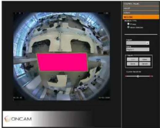
- Click Draw (the image shrinks slightly while you are drawing the zone).
- Left-click to set the initial point. Click several times around the area until defining a suitable polygon. Click the starting point again to complete the region.
Click Clear to restart drawing the polygon or cancel the current action.
-
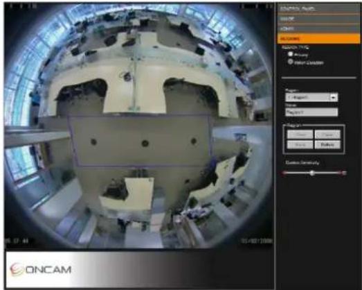
Click Save to store the region in the dropdown Region list. The motion detection appears in the image as a blue polygon outline.
-
Repeat as necessary for up to 8 regions.
Improve Motion Detection efficiency by modifying the Sensitivity, Threshold, Persistence and Latency settings.
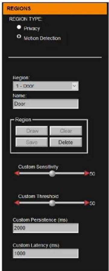
Sensitivity. Control the sensitivity of the camera to object
movement. Where low-contrast objects are difficult to capture, increase the sensitivity to detect these objects. Setting the sensitivity lower requires more motion to activate an alarm.
Note: High sensitivity values in noisy environments may cause false alarms.
Threshold. The amount of moving pixels required to raise a motion alarm are determined by the threshold setting. Motion alarms are caused by the cumulative moving pixels regardless of their distribution. Setting the threshold higher increases the motion's time to activate an alarm.
Note: Low motion threshold in noisy environments may cause increased false alarms.
Motion Persistence. The period when motion is detected in a frame prior to raising an alarm is the persistence. Raising a motion alarm immediately after the motion might lead to false alarms in noisy environments. Use the motion persistence setting to ensure the system raises an alarm only when persistent motion exists.
Motion Latency. Motion latency defines how many frames in an alarm remains true after motion stops. A low latency allows a rapid succession of motion events to appear as multiple alarms. A higher setting will group rapid triggers into a single alarm event.
Notes:
- To delete a region, select the region in the Region dropdown list and click Delete. This also deletes any saved name and returns the specific region number to default settings.
- Use the Alarm Settings to configure detected motion as an alarm trigger that activates an alarm action. See Alarm, page 39.
natural_image
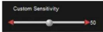
Interior view of a large industrial facility with circular machinery and structural elements (no visible text or symbols)- Adjust the motion sensitivity by moving the Custom Sensitivity bar slider left or right to the desired value.
Fine-adjust the value by clicking the red arrows on the slider. Apply Custom Sensitivity to all motion detection regions.

An Alarm Bell symbol flashes at the bottom of the window giving you a visual indication of the Custom Sensitivity setting. The alarm bell symbol displays when you enable the Alarm Trigger Motion Detection and displays when the Motion Detection event has triggered.
NOTE: Setup and test motion detection by setting the threshold above any natural motion that is occurring in the scene to eliminate false alarms. Set the threshold to a minimum and gradually raise the threshold until natural motion no longer triggers the alarm.
9 Connecting directly to the camera streams
Connect directly to camera streams to acquire JPEG and MJPEG (H.264) video streams.
9.1 JPEG Snapshot
Access JPEG images from your camera by using your camera's IP address and port creating the following URLs.
4MP JPEG http://camera_ip_address:port_number/mjpg/snapshot.cgi?camera=13
2MP JPEG http://camera_ip_address:port_number/mjpg/snapshot.cgi?camera=25
1MP JPEG http://camera_ip_address:port_number/mjpg/snapshot.cgi?camera=12
1/4MP JPEG http://camera_ip_address:port_number/mjpg/snapshot.cgi?camera=26
9.2 MJPEG / H.264 Video Stream
Using the Web Interface, find your camera's stream to determine the video setup. Using your camera's IP address and the appropriate URL, connect to your camera's video stream using your media player.
MJPEG
| 4MP JPEG | http://camera_ip_address:port_number/video.cgi?camera=13 |
| 2MP JPEG | http://camera_ip_address:port_number/video.cgi?camera=25 |
| 1MP JPEG | http://camera_ip_address:port_number/video.cgi?camera=12 |
| 1⁄4MP JPEG | http://camera_ip_address:port_number/video.cgi?camera=26 |
H.264
| 4MP JPEG | rtsp://camera_ip_address:554/h264/video.sdp?camera=13 |
| 2MP JPEG | rtsp://camera_ip_address:554/h264/video.sdp?camera=25 |
| 1MP JPEG | rtsp://camera_ip_address:554/h264/video.sdp?camera=12 |
| 14 MP JPEG | rtsp://camera_ip_address:554/h264/video.sdp?camera=26 |
For example, the Evolution camera is the IP address 192.168.0.200, port 554 (H.264 RTSP stream is port 554).
- From the Camera Web Interface, go to Admin > Video Setup
- Check the Second Camera check box.
- Select H.264 from the Stream dropdown menu,
- Select 0.25M from the Resolution dropdown menu,
- Click Set the Video Stream.
Using the following sample URLs provides the two video streams using your media player.
• 4MP H.264: rtsp://192.168.0.200:554/h264/video.sdp?camera=13
• 1/4MP MJPEG: http://192.168.0.200:80/video.cgi?camera=26
For MJPEG streaming the username and password are required. By default, use "admin" for both the username and password.
10 Connecting through ONVIF Profile S or PSIA
Use an Evolution camera with an ONVIF Conformant Device hardware driver when adding the camera hardware to your NVR System. Set the camera to the desired mode before adding the camera to your NVR system.
Note: The ONVIF driver uses RTSP for transferring the video from the camera. The Evolution camera sends the MJPEG data using the MJPEG RTP standard RFC 2435. The RFC 2435 standard does not work using JPEG images with a width greater than 2040. This means RTSP does not transfer the larger MJPEG video streams from the camera. Stream any other MJPEG or any H.264 resolution using the ONVIF driver.
11 Troubleshooting and Technical Support
Use the following guide to ensure all components of the system are properly working.
| Web Interface unavailable in browser | Use the IP Configuration Tool to confirm that you are looking at the correct address and there are no IP address conflicts.Check your own network settings to ensure the camera is on the same subnet, or is accessible by routing. |
| Web Interface fails to show a live image | Check your browser security settings. |
| Motion detection is not working properly | There must be at least one motion detection region defined and in use. On the Motion Detection panel, the VMD mode must be set to Motion Detection.Check the size and sensitivity controls to ensure that movement is detected. |
| Camera image stops or drops frames | This is commonly due to a network connectivity or bandwidth issues, especially for cameras connected to wireless networks or the public Internet.Try reducing the JPEG quality or resolution settings from the camera Web interface. |
| One portion of the image is over or under-exposed | Set the Brightness or use an EV setting which will add over or under exposure to the scene light. |
| There are bright or dark areas in the scene and no detail can be seen | Enable the WDR feature. This increases the contrast in darker and brighter areas of the scene. Adjust the WDR setting depending on the light differences to obtain the best image. See Wide Dynamic Range, page 35.Enhance the image by adjusting the EV settings so the bright areas are not over-exposed and the dark areas are sufficiently exposed.In most lighting conditions, the WDR setting should not be required. |
11.1 Contact
Send an email to support@oncamgrandeye.com.
Include in your email the following.
- Problems detailed description
- Camera model numbers
• Relevant configuration information
11.2 Revision History
| Date | Revision | Description |
| 2016-12-10 E | Replaced M23 references with 1.5-inch NPTCorrected login / password reference incorrectly showing initial caps | |
| 2016-11-14 D | Updates impacted from firmware version 1.9.12 | |
| 2016-11-04 C | Added Stainless Steel Surface and Pendant mount camera informationModifications for firmware version 1.9.11 | |
| 2016-09-12 | B | Added Indoor Recessed camera information |
12 Copyright and Legal Notices
ONCAM GLOBAL GROUP END-USER LICENSE AGREEMENT NOTICE TO USER: PLEASE READ YOUR APPLICABLE END-USER SOFTWARE LICENSE AGREEMENT (EULA) CAREFULLY BEFORE INSTALLING THE SOFTWARE AS IT IMPACTS YOUR LEGAL RIGHTS AND REMEDIES PERTAINING TO THE USE OF THE SOFTWARE. PLEASE CONTACT ONCAM GLOBAL GROUP FOR A COPY OF YOUR APPLICABLE LICENSE.
By copying, installing or using all or any portion of the software you accept all the terms and conditions of the EULA and any amendments thereto, including, but not limited to, the limitations on use set forth in Article 2; transferability in Article 4; warranty in Articles 6 and 7; liability in Article 8; connectivity and privacy in Section 14; and specific provisions and exceptions in Article 15. You agree that the EULA is like any written negotiated instrument signed by you. The EULA is enforceable against you and any legal entity that obtained the software and on whose behalf it is used; for example, if applicable, your employer. Do not use or install the software if you do not agree to the terms of this license.
Please contact Oncam for terms of and limitations on returning the software for a refund. Oncam and its suppliers own or license all intellectual property in the software. The software is licensed, not sold. Oncam permits you to copy, download, install, use, or otherwise benefit from the functionality or intellectual property of the software only in accordance with the terms of the EULA and any amendments thereto. Use of some Oncam and some third party materials and other services included in or accessed through the software may be subject to other terms and conditions typically found in a separate license agreement. The software may include product activation and other technology designed to prevent unauthorized use and copying. This technology may cause your computer to automatically connect to the Internet and may prevent uses of the software that are not permitted.
13 Additional Online Resources
13.1 Technical Specifications
Oncam is constantly working on new features and functionalities for its Evolution camera range. For the latest Technical Specifications, go to the Oncam website and download the latest product specification.
Indoor
www.oncamgrandeye.com/security-systems/evolution-05-indoor-camera.html
Outdoor
www.oncamgrandeye.com/security-systems/evolution-05-outdoor-camera.html
Concealed
www.oncamgrandeye.com/security-systems/evolution-05-concealed-camera.html
Recessed
www.oncamgrandeye.com/security-systems/evolution-05-recessed-camera.html
Stainless Steel
www.oncamgrandeye.com/security-systems/evolution-stainless-steel.html
13.2 Oncam 360-degree Viewer
Download the latest Oncam 360-degree Live Viewer and Instruction Manual for the Evolution range of 360-degree IP Cameras. The Instruction Manual describes how to use the Oncam 360-degree Viewer to view and dewarp live images from any Oncam camera connected to the same network. There is no setup required as the Viewer automatically finds any Oncam IP cameras connected to the same network.
http://www.oncamgrandeye.com/security-systems/360-camera-viewer
13.3 OnVu360 Mobile Application (iOS and Android)
OnVu360 for mobiles enables users to experience surveillance through 360 degrees in the palm of your hand. The OnVu360 gives you the ability to monitor your 360-degree cameras in real-time enabling anytime access to the information.
Use the pinch to zoom features to Navigate 360-degree video (like iOS or Android device).
The OnVu360 app streams up to 5 MP, streaming over Wi-Fi, 3G and 4G/LTE networks.
Take a snapshot to save precious data when using over a cellular-data network.
Android
From https://play.google.com/store > Search OnVu360
iOS
From within the iTunes Store > Search OnVu360
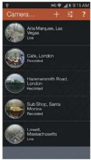
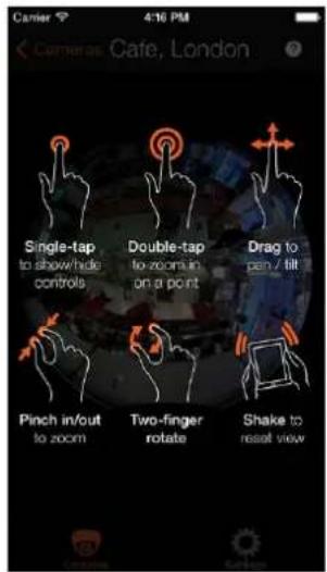
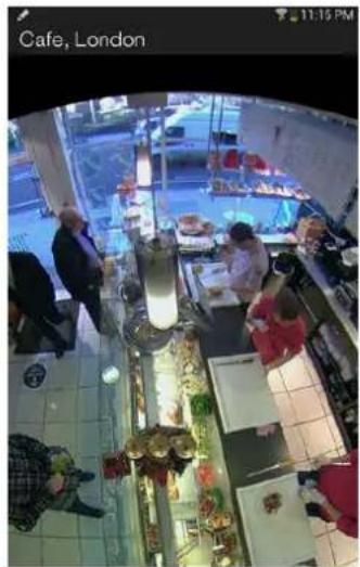
14 Frame Rate, Resolution & Storage Requirements
| H.264 Default Settings | |||||
| 4 MP | (2144x1944) | 10 FPS | Constant bit rate settings | 5 Mbps | 24 HRS = 54GB* |
| 2 MP | (1488 x1360) | 15 FPS | Constant bit rate settings | 3 Mbps | 24 HRS = 40GB* |
| 1 MP | (1056 x 960) | 15 FPS | Constant bit rate settings | 1.5 Mbps | 24 HRS = 16GB* |
| 14 MP | (528 x 480) | 15 FPS | Constant bit rate settings | 0.8 Mbps | 24 HRS = 8GB* |
* Based on the same scene, with constant average light conditions
| MJPEG Default Settings | |||||
| 4 MP | (2144x1944) | 10 FPS | Average file size 640 KB | Average bit rate 52.4 Mbps | 24 HRS = 552.96 GB* |
| 2 MP | (1488 x1360) | 15 FPS | Average file size 350 KB | Average bit rate 43.0 Mbps | 24 HRS = 453.60 GB* |
| 1 MP | (1056 x 960) | 15 FPS | Average file size 188 KB | Average bit rate 23.1 Mbps | 24 HRS = 243.65 GB* |
| 14 MP | (528 x 480) | 15 FPS | Average file size 62 KB | Average bit rate 7.6 Mbps | 24 HRS = 80.35 GB* |
* Based on the same scene, with constant average light conditions
Notes:
Values for frame rate, size, and bandwidth are approximate and influenced by compression, quality settings, number of simultaneous viewers, and the amount of detail and movement in a scene.
Additional CGI commands are available. Software developers requiring the full API interface should contact support@oncamgrandeye.com for additional details.
15 NVR and Storage Partners
For an up-to-date list of NVR / VMS partners supporting the Oncam 360° IP cameras, visit the Oncam web site www.oncamgrandeye.com.
- Evolution 05 Camera Range
- Installation & User Manual
- Manual Copyright
- Trademarks and Third-Party Copyrights
- Important Safety Instructions
- WARNING
- RISK OF EXPLOSION IF REPLACING A BATTERY WITH AN INCORRECT BATTERY TYPE
- Contents
- List of Figures
- List of Tables
- Overview
- Fisheye View
- Panoramic View
- Camera Range
- Power Requirements
- Audio Input
- Alarms
- Camera Placement and Orientation
- Ceiling Mount
- Wall Mount
- Table Mount
- Coverage Area
- Overhead Viewing Angle
- Lighting
- Camera Installation
- Preparation
- Inserting an SD card
- Compatible SD cards
- Ethernet and Power Cabling
- External I/O Cabling
- Alarm Out
- Alarm In
- Indoor Camera
- Parts List
- Installation Steps
- Indoor Concealed Camera
- Parts List
- Installation Steps
- Indoor Recessed Camera
- Parts List
- Figure 5 Indoor Recessed Below Ceiling Installation
- Outdoor Camera
- Parts Supplied
- Installation Steps
- Preparation
- CAUTION: Do not alter the Gore vent. Altering the Gore vent impacts the cameras performance and moisture may build within the bubble dome.
- NOTICE: Only one wire should pass through a cable entry grommet to avoid seal issues. Passing more than one wire through the grommet invalidates the warranty.
- Mounting
- Sun Shield
- Stainless Steel Camera – Surface Mount
- Parts Supplied
- Installation Steps
- Preparation
- Mounting
- Stainless Steel Camera – Pendant Mount
- Parts Supplied
- Installation Steps
- Preparation
- Mounting
- Camera Mounts
- Wall Mount
- Rough Surfaces or over Electrical Boxes
- Corner Mount
- Pole Mount
- Pendant Mount
- Test
- Indoor Camera
- Outdoor Camera
- Dome Handling and Cleaning
- First Time Operation
- DHCP
- Static IP Installation
- Finding Available Cameras
- Assigning an IP Address
- Connecting to the Camera
- Media Player Requirements
- QuickTime
- VLC
- Camera Web Interface
- Control Panel
- Image
- Mains Frequency
- Image Controls
- Sharpen
- EV Compensation
- Wide Dynamic Range
- Switch to Monochrome
- Switch Delay Time
- Image Time and Date Overlay
- Camera Mount
- Administration
- Network
- User Management
- User
- Operator
- Administrator
- Alarms
- Camera
- Clock
- Stream
- Audio
- Recordings
- SD Card Operations
- Factory Defaults
- Regions
- Privacy
- Notes:
- Motion Detection
- Connecting directly to the camera streams
- JPEG Snapshot
- MJPEG / H.264 Video Stream
- Connecting through ONVIF Profile S or PSIA
- Troubleshooting and Technical Support
- Contact
- Revision History
- Copyright and Legal Notices
- Additional Online Resources
- Technical Specifications
- Oncam 360-degree Viewer
- OnVu360 Mobile Application (iOS and Android)
- Android
- iOS
- Frame Rate, Resolution & Storage Requirements
- NVR and Storage Partners
Brand : Pelco
Model : Evolution EVO-05NSD
Category : Security Camera