Sarix TI2650-1 - Security Camera Pelco - Free user manual and instructions
Find the device manual for free Sarix TI2650-1 Pelco in PDF.


| Product Type | Thermal & Visible IP Security Camera |
| Brand | Pelco |
| Model | Sarix TI2650-1 |
| Dimensions (W x D x H) | 135 mm x 202 mm x 169 mm (5.32" x 7.95" x 6.65") |
| Weight | 2.4 kg (5.3 lb) |
| Power Input | 12–32 VDC or PoE (IEEE 802.3af/at) |
| Power Consumption | 7 W typical, 20 W max |
| Thermal Imager | Uncooled ASi Microbolometer, 640 × 480 VGA, 17 μm pixel, 7.5–14 μm spectral band |
| Thermal Lens | 50 mm f/1.2 athermalized fixed focus, horizontal FOV 12.4° |
| Visible Camera | 1/4" Color HD CMOS, up to 1280 × 720 resolution |
| Video Compression | H.264, Motion JPEG |
| Frame Rate | 9 Hz (model variant) |
| Network Protocols | IPv4, HTTP, HTTPS, RTSP, DHCP, ONVIF Profile S |
| Default IP Address | 192.168.0.20 |
| Environmental Rating | IP66 (NEMA 4X equivalent) |
| Operating Temperature | -40°C to +55°C (-40°F to +131°F) |
| Storage Temperature | -40°C to +71°C (-40°F to +160°F) |
| Mounting Options | Wall mount (TIWM) or pole mount (TIPA) accessories |
| Cleaning Instructions | Use only wipes approved for optical equipment; no chemicals |
| Repair Policy | Do not attempt repairs; contact Pelco support. Warranty void if opened. |
Frequently Asked Questions - Sarix TI2650-1 Pelco
User questions about Sarix TI2650-1 Pelco
0 question about this device. Answer the ones you know or ask your own.
Ask a new question about this device
Download the instructions for your Security Camera in PDF format for free! Find your manual Sarix TI2650-1 - Pelco and take your electronic device back in hand. On this page are published all the documents necessary for the use of your device. Sarix TI2650-1 by Pelco.
USER MANUAL Sarix TI2650-1 Pelco
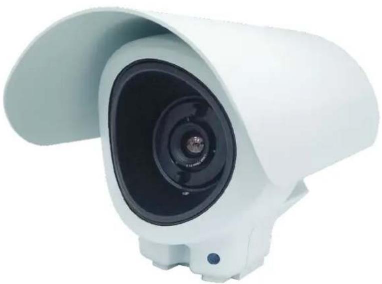
Sarix TI Series Camera
natural_image
White camera lens with a curved top and base, no visible text or symbolsUser Manual
C6622M
Pelco Troubleshooting Contact Information
If the instructions provided fail to solve your problem, contact Pelco Product Support at 1-800-289-9100
(USA and Canada) or +1-559-292-1981 (international) for assistance. Be sure to have the serial number available when calling.
Do not try to repair the unit yourself. Leave maintenance and repairs to qualified technical personnel only.
PELCO®
List of Revisions
| No. | Date | Description | Page Number |
| 1.0 | New Release All | ||
Table of Contents
1. Important Notices .... 1-8
1.1 Regulatory Notices [FCC Class A].... 1-8
1.1.1 Radio and Television Interference.... 1-8
1.2 Legal Notice [Audio Notice].... 1-8
1.3 Video Quality Caution 1-9
1.3.1 Frame Rate Notice Regarding User Selected Options.... 1-9
1.4 Open Source Software 1-9
1.5 CCC Power Cord Statement 1-9
1.5.1 2.4 GHZ Radio Device....1-10
1.6 ESD Warning 1-10
1.7 Warranty.... 1-10
1.8 Network Topology Statement.... 1-10
2. Overview 2-13
2.1 Overview....2-14
2.2 Features 2-14
2.3 Physical Description of the Camera....2-15
2.4 Marking....2-16
2.5 Sarix TI Web GUI....2-17
2.6 Technical Data and Specifications....2-18
2.6.1 System Specifications.... 2-18
2.6.2 Configurations 2-19
2.6.3 Thermal Camera 2-20
2.6.4 CMOS Camera 2-20
3. Safety 3-1
3.1 Safety Conventions 3-1
3.2 Safety During Installation 3-2
3.3 Safety During Maintenance 3-2
4. Installation....4-1
4.1 Unpacking....4-1
4.2 Camera Installation 4-2
4.2.1 Installation Guidelines and Preparation....4-2
4.2.2 Mechanical Interface Preparation....4-3
4.2.3 Wall Mount Configuration 4-4
4.2.4 Pole Mount Configuration 4-5
4.2.5 Electrical ICD IP PoE Cable 4-6
5. Operation 5-1
5.1 First Time Credentials Setup.... 5-2
5.2 Logging Into Sarix TI Camera Web GUI 5-3
5.3 Changing Your Password.... 5-5
5.4 Main Window Overview 5-6
5.5 Live View Window 5-7
5.6 Status Window.... 5-8
5.6.1 System Tab.... 5-9
5.6.2 Thermal Tab 5-10
5.6.3 Day Tab 5-12
5.6.4 Disabling / Enabling a Camera 5-13
5.7 Network Window 5-15
5.7.1 Setting of IP Address 5-16
5.7.2 Setting an Auto IP Address (DHCP) 5-16
5.7.3 Setting a Manual DNS Server Address 5-17
5.7.4 Settings of HTTPS Connection.... 5-17
5.7.5 Setting the Network Interface 5-17
5.7.6 Resetting Network Settings.... 5-18
5.7.7 Restarting ONVIF Service 5-18
5.7.8 Certificates 5-19
5.8 Streaming Window 5-21
5.8.1 Thermal Tab 5-21
5.8.2 Day Tab 5-25
5.8.3 General Configuration Tab 5-28
5.9 Image Processing Window 5-29
5.9.1 Thermal Tab 5-29
5.9.2 Day Tab 5-37
5.10 Analytics Window 5-41
5.10.1 Regions Tab 5-42
5.10.2 Ignore Regions Tab 5-46
5.10.3 Learning Tab 5-48
5.10.4 Analytics Settings.... 5-49
5.11 System Window.... 5-51
5.11.1 Admin Tab 5-51
5.11.2 Logs Tab.... 5-57
5.11.3 Date and Time Tab 5-58
5.11.4 File Upload Tab.... 5-60
5.11.5 User Management Tab 5-60
5.12 Logging Out from the Web GUI 5-62
- Maintenance 6-63
6.1 Visual Inspection 6-63
6.2 Cleaning.... 6-63 - Ordering Information 7-64
7.1 Ordering Information....7-64
7.2 Ordering Accessories 7-64
8. Index....8-65
List of Figures
Figure 2-1: Sarix TI Camera General View 2-14
Figure 2-2: Physical Description of the Camera 2-15
Figure 2-3: Sarix TI Label.... 2-16
Figure 2-4: Sarix TI Web GUI 2-17
Figure 4-1: Sarix TI Camera Package General View.... 4-1
Figure 4-2: Mechanical Interface Preparation - Camera Dimensions.... 4-3
Figure 4-3: Camera Installation - Wall Mount Configuration 4-4
Figure 4-4: Camera Installation - Pole Mount Configuration 4-5
Figure 4-5: Electrical ICD IP PoE Cable 4-6
Figure 5-1: Sarix TI Web GUI – First Time Setup .... 5-2
Figure 5-2: Sarix TI Web GUI - Status Window (before Login).... 5-3
Figure 5-3: Login Window....5-3
Figure 5-4: Login Window – Entering Username and Password.... 5-4
Figure 5-5: Sarix TI Web GUI - Status Window (after Login).... 5-4
Figure 5-6: Changing Your Password - Drop Down Menu .... 5-5
Figure 5-7: Sarix TI Web GUI - Changing Your Password.... 5-5
Figure 5-8: Main Window Overview - Main Areas.... 5-6
Figure 5-9: Live View Window (example)....5-7
Figure 5-10: Status Window (all collapsed)....5-8
Figure 5-11: Status Window - System Tab 5-9
Figure 5-12: Status Window - Thermal Tab 5-10
Figure 5-13: Status Window - Day Tab 5-12
Figure 5-14: Disabling / Enabling a Camera - System Reboot 5-13
Figure 5-15: Disabling / Enabling a Camera - System Reboot Approval.... 5-14
Figure 5-16: Network Window - Basic Settings Tab.... 5-15
Figure 5-17: Network Window - Changing an Address.... 5-16
Figure 5-18: Network Window - Setting Network Interface .... 5-17
Figure 5-19: Network Window - Resetting IP Address Approval 5-18
Figure 5-20: Network Window - ONVIF Reload 5-18
Figure 5-21: Certificates - Creating a Certificate Request.... 5-19
Figure 5-22: Certificates - Generating a Self-Signed Certificate 5-19
Figure 5-23: Certificates - Uploading a Certificate.... 5-20
Figure 5-24: Streaming Window - Thermal Tab.... 5-21
Figure 5-25: Streaming Window - Thermal Tab - Main Stream.... 5-22
Figure 5-26: Streaming Window - Thermal Tab - Secondary Stream 5-24
Figure 5-27: Streaming Window - Day Tab - Main Stream.... 5-25
Figure 5-28: Streaming Window - Day Tab - Secondary Stream 5-27
Figure 5-29: Streaming Window - General Configuration Tab 5-28
Figure 5-30: Image Processing Window - Thermal Tab.... 5-29
Figure 5-31: Image Processing Window - Thermal Tab - Basic Settings.... 5-30
Figure 5-32: Image Processing Window - Thermal Tab - Signal Processing Settings.... 5-31
Figure 5-33: Image Processing Window - Thermal Tab - Gain Control Settings 5-32
Figure 5-34: Image Processing Window - Thermal Tab - Advanced Settings....5-33
Figure 5-35: Image Processing Window - Thermal Tab - Color Processing Settings....5-34
Figure 5-36: Image Processing Window - Histogram Calculation ROI (1 of 3)....5-34
Figure 5-37: Image Processing Window - Histogram Calculation ROI (2 of 3)....5-35
Figure 5-38: Image Processing Window - Histogram Calculation ROI (3 of 3)....5-36
Figure 5-39: Image Processing Window - Day Tab 5-37
Figure 5-40: Image Processing Window - Day Tab - Geometry Settings....5-38
Figure 5-41: Image Processing Window - Day Tab - Misc Properties Settings....5-39
Figure 5-42: Analytics Window (all collapsed)....5-41
Figure 5-43: Analytics Window - Regions Tab....5-42
Figure 5-44: Analytics Window - Regions Tab - Region Options 5-43
Figure 5-45: Analytics Window - Regions Tab - Area ROI....5-45
Figure 5-46: Analytics Window - Regions Tab - Fence ROI....5-45
Figure 5-47: Analytics Window - Ignore Regions Tab .... 5-46
Figure 5-48: Analytics Window - Ignore Regions Tab – Ignore Regions ROI (1 of 2)....5-47
Figure 5-49: Analytics Window - Ignore Regions Tab – Ignore Regions ROI (2 of 2)....5-47
Figure 5-50: Analytics Window - Learning Tab 5-48
Figure 5-51: Analytics Window - Analytics Settings....5-49
Figure 5-52: System Window - Admin Tab .... 5-51
Figure 5-53: System Window - Admin Tab - Restart Aproval ....5-51
Figure 5-54: System Window - Admin Tab - Restart....5-52
Figure 5-55: System Window - Admin Tab - Archive System Files .... 5-52
Figure 5-56: System Window - Admin Tab - Save As Site Approval 5-53
Figure 5-57: System Window - Admin Tab - Save As Site .... 5-53
Figure 5-58: System Window - Admin Tab - Export Site Approval....5-54
Figure 5-59: System Window - Admin Tab - Site Defaults Approval....5-54
Figure 5-60: System Window - Admin Tab - Site Defaults .... 5-55
Figure 5-61: System Window - Admin Tab - Factory Defaults Approval....5-55
Figure 5-62: System Window - Admin Tab - Factory Defaults .... 5-56
Figure 5-63: System Window - Logs Tab 5-57
Figure 5-64: System Window - Date and Time Tab....5-58
Figure 5-65: System Window - Date and Time Tab - Synchronizing with Browser Time....5-59
Figure 5-66: System Window - Date and Time Tab - Synchronizing with NTP 5-59
Figure 5-67: System Window - File Upload Tab .... 5-60
Figure 5-68: System Window - User Management Tab....5-60
Figure 5-69: System Window - User Management Tab - Adding a User ....5-61
Figure 5-70: System Window - User Management Tab - Editing User Details....5-62
Figure 5-71: Logging Out from the Web GUI - Drop Down Menu....5-62
List of Tables
Table 2-1: Technical Data and Specifications - System Specifications.... 2-18
Table 2-2: Technical Data and Specifications - Configurations.... 2-19
Table 2-3: Technical Data and Specifications - Thermal Camera.... 2-20
Table 2-4: Technical Data and Specifications - CMOS Camera 2-20
Table 4-1: Electrical ICD IP PoE Cable - Pinout.... 4-6
Table 7-1: Ordering Information for 30Hz Camera.... 7-64
Table 7-2: Ordering Information for 9Hz Camera....7-64
Table 7-3: Ordering Accessories.... 7-64
1. Important Notices
1.1 Regulatory Notices [FCC Class A]
This device complies with Part 15 of the FCC Rules. Operation is subject to the following two conditions: (1) this device may not cause harmful interference, and (2) this device must accept any interference received, including interference that may cause undesired operation.
1.1.1 Radio and Television Interference
This equipment has been tested and found to comply with the limits of a Class A digital device, pursuant to Part 15 of the FCC rules. These limits are designed to provide reasonable protection against harmful interference when the equipment is operated in a commercial environment. This equipment generates, uses, and can radiate radio frequency energy and, if not installed and used in accordance with the instruction manual, may cause harmful interference to radio communications. Operation of this equipment in a residential area is likely to cause harmful interference in which case the user will be required to correct the interference at his own expense.
Changes and Modifications not expressly approved by the manufacturer or registrant of this equipment can void your authority to operate this equipment under Federal Communications Commission's rules.
To maintain compliance with FCC regulations shielded cables must be used with this equipment. Operation with non-approved equipment or unshielded cables is likely to result in interference to radio and television reception.
This Class A digital apparatus complies with Canadian ICES-003.
1.2 Legal Notice [Audio Notice]
SOME PELCO EQUIPMENT CONTAINS, AND THE SOFTWARE ENABLES, AUDIO/VISUAL AND RECORDING CAPABILITIES, THE IMPROPER USE OF WHICH MAY SUBJECT YOU TO CIVIL AND CRIMINAL PENALTIES. APPLICABLE LAWS REGARDING THE USE OF SUCH CAPABILITIES VARY BETWEEN JURISDICTIONS AND MAY REQUIRE, AMONG OTHER THINGS, EXPRESS WRITTEN CONSENT FROM RECORDED SUBJECTS. YOU ARE SOLELY RESPONSIBLE FOR INSURING STRICT COMPLIANCE WITH SUCH LAWS AND FOR STRICT ADHERENCE TO ANY/ALL RIGHTS OF PRIVACY AND PERSONALTY. USE OF THIS EQUIPMENT AND/OR SOFTWARE FOR ILLEGAL SURVEILLANCE OR MONITORING SHALL BE DEEMED UNAUTHORIZED USE IN VIOLATION OF THE END USER SOFTWARE
AGREEMENT AND RESULT IN THE IMMEDIATE TERMINATION OF YOUR LICENSE RIGHTS THEREUNDER.
1.3 Video Quality Caution
1.3.1 Frame Rate Notice Regarding User Selected Options
Pelco systems are capable of providing high quality video for both live viewing and playback. However, the systems can be used in lower quality modes, which can degrade picture quality, to allow for a slower rate of data transfer and to reduce the amount of video data stored. The picture quality can be degraded by either lowering the resolution, reducing the picture rate, or both. A picture degraded by having a reduced resolution may result in an image that is less clear or even indiscernible. A picture degraded by reducing the picture rate has fewer frames per second, which can result in images that appear to jump or move more quickly than normal during playback. Lower frame rates may result in a key event not being recorded by the system.
Judgment as to the suitability of the products for users' purposes is solely the users' responsibility. Users shall determine the suitability of the products for their own intended application, picture rate and picture quality. In the event users intend to use the video for evidentiary purposes in a judicial proceeding or otherwise, users should consult with their attorney regarding any particular requirements for such use.
1.4 Open Source Software
This product includes certain open source or other software originated from third parties that is subject to the GNU General Public License (GPL), GNU Library/Lesser General Public License (LGPL) and different and/or additional copyright licenses, disclaimers, and notices.
The exact terms of GPL, LGPL, and some other licenses are provided to you with this product. Please refer to the exact terms of the GPL and LGPL at http://www.fsf.org (Free Software Foundation) or http://www.opensource.org (Open Source Initiative) regarding your rights under said license. You may obtain a complete corresponding machine-readable copy of the source code of such software under the GPL or LGPL by sending your request to digitalsupport@pelco.com; the subject line should read Source Code Request. You will then receive an email with a link for you to download the source code.
This offer is valid for a period of three (3) years from the date of the distribution of this product by Pelco.
1.5 CCC Power Cord Statement
Models shipped to China do not include power cords.
NOTE
A CCC approved power cord must be used to power the equipment when used in China
1.5.1 2.4 GHZ Radio Device
WARNING: This product is sensitive to Electrostatic Discharge (ESD). To avoid ESD damage to this product, use ESD safe practices during installation. Before touching, adjusting or handling this product, correctly attach an ESD wrist strap to your wrist and appropriately discharge your body and tools. For more information about ESD control and safe handling practices of electronics, please refer to ANSI/ESD S20.20-1999 or contact the Electrostatic Discharge Association (www.esda.org).
1.7 Warranty
For information about Pleco's product warranty and thereto related information, refer to www.pelco.com/warranty.
1.8 Network Topology Statement
IMPORTANT NOTE. PLEASE READ. The network implementation is shown as a general representation only and is not intended to show a detailed network topology. Your actual network will differ, requiring changes or perhaps additional network equipment to accommodate the system as illustrated. Please contact your local Pelco representative to discuss your specific requirements.
List of Acronyms and Abbreviations
| AWG: | American Wire Gauge | NUC: | Non-Uniformity Correction |
| CBR: | Constant Bit Rate | NV: | Night Vision |
| Histogram: | Accurate representation of the distribution of numerical data. | ONVIF: | Open Network Video Interface Forum |
| CE: | Comminute European | P/N: | Part Number |
| CMOS: | Complementary Metal-Oxide Semiconductor | PoE: | Power Over Ethernet |
| DC: | Direct Current | QVGA+: | Quarter Video Graphics Array (384 ×288) |
| DFPA: | Digital Focal Plan Array | RH: | Relative Humidity |
| DHCP: | Dynamic Host Configuration Protocol | ROI: | Region Of Interest |
| DNS: | Domain Name System | RTN: | Return |
| FCC: | Federal Communications Commission | RTP: | Real Time Protocol |
| I-frame: | Infra-coded frame | RTSP: | Real-Time Streaming Protocol |
| FM: | Firmware | S/N: | Serial Number |
| FOV: | Field Of View | SDK: | Software Development Kit |
| FPS: | Frames Per Second | VMS: | Video Management System |
| GND: | Ground | SSL: | Secure Sockets Layer |
| GOP: | Group of Pictures | SW: | Software |
| GUI: | Graphical User Interface | TCP: | Transmission Control Protocol |
| HD: | High Definition | TINT: | Time Integration |
| HTTP: | Hypertexts Transfer Protocol | TLS: | Transport Layer Security |
| HTTPS: | HyperText Transfer Protocol Secure | URI: | Uniform Resource Indicator |
| IEEE: | Institute of Electrical and Electronics Engineers | V bus | CTIA reference voltage |
| IP: | Internet Protocol | VBR: | Variable Bit Rate |
| IR: | Infrared | VDC: | Volts, Direct Current |
| JPEG: | Joint Photographic Expert Group | VDDA: | Analog supply fixed |
| LAN: | Local Area Network | VGA: | Video Graphics Array (640 × 480) |
| MAC: | Media Access Control | VGSK: | Compensation microbolometer - transistor gate voltage |
| mK: | milli-Kelvin | WWW: | World Wide Web |
| NETD: | Noise Equivalent Temperature Difference | Pipeline: | data processing elements, connected in series, where the output of one element is the input of the next one. |
Scope of This Manual
This manual provides the necessary information for introducing, installing, operating and maintaining the Sarix TI Series Camera.
The manual in intended for use by technicians and operators and consists of the following chapters:
Chapter 2: Overview:
Introduces the Sarix TI Series Camera and its web GUI features.
Chapter 3: Safety:
Provides safety instructions that technicians should be aware of during the installation, operation and maintenance of the Sarix TI Series Camera.
Chapter 4: Installation: Provides instructions for installing the Sarix TI Series Camera.
Chapter 5: Operation: Provides operating instructions for the Sarix TI Series Camera web GUI.
Chapter 6: Maintenance:
Provides the Sarix TI Series Camera preventive maintenance instructions.
Chapter 7: Ordering Information:
Provides information for purchasing the Sarix TI Series Camera and accessories.
➢ Index:
Provides a list, arranged in alphabetical order, of keywords found throughout this manual.
2. Overview
This chapter introduces the Sarix TI Series Camera and its web GUI features.
The chapter consists of the following sections:
Section 2.1: Overview
Section 2.2: Features
Section 2.3: Physical Description of the Camera
Section 2.5: Sarix TI Web GUI
Section 2.6: Technical Data and Specifications
2.1 Overview
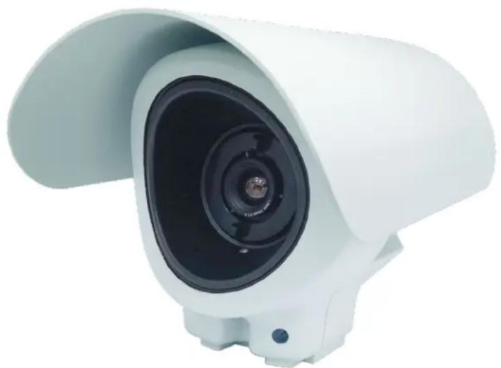
Sarix TI Camera is a state of the art observation system, boasting an incredibly easy installation with thermal and visual capabilities. The Sarix TI line of cameras is a broad portfolio of high performance outdoor rated cameras for 24/7 perimeter surveillance, observation, and monitoring of critical infrastructure and sensitive sites.
Equipped with thermal and visible-light channels, the Sarix TI meets global Open Network Video Interface Forum (ONVIF) standards to ensure interoperability of hardware and software products for easy integration to both existing and new infrastructures, regardless of manufacturer.
The Sarix TI is ruggedly designed to withstand the harshest weather and environmental conditions, including rain, direct sunlight, high humidity, dust, heat, and cold.
The Sarix TI uses new and innovative open uncooled 17 640 × 480 or 384 × 288 resolution thermal core and video enhancement algorithm.
Figure 2-1: Sarix TI Camera General View
natural_image
White camera lens with a curved top and black lens, shown against a white background (no text or symbols visible)2.2 Features
Both visible and Video Graphics Array (VGA) thermal channels
ONVIF Profile S compliant
Easy installation
▶ Advanced optics
Low cost of ownership
Best support for analytics
Rugged design
▶ Enhanced image processing
2.3 Physical Description of the Camera
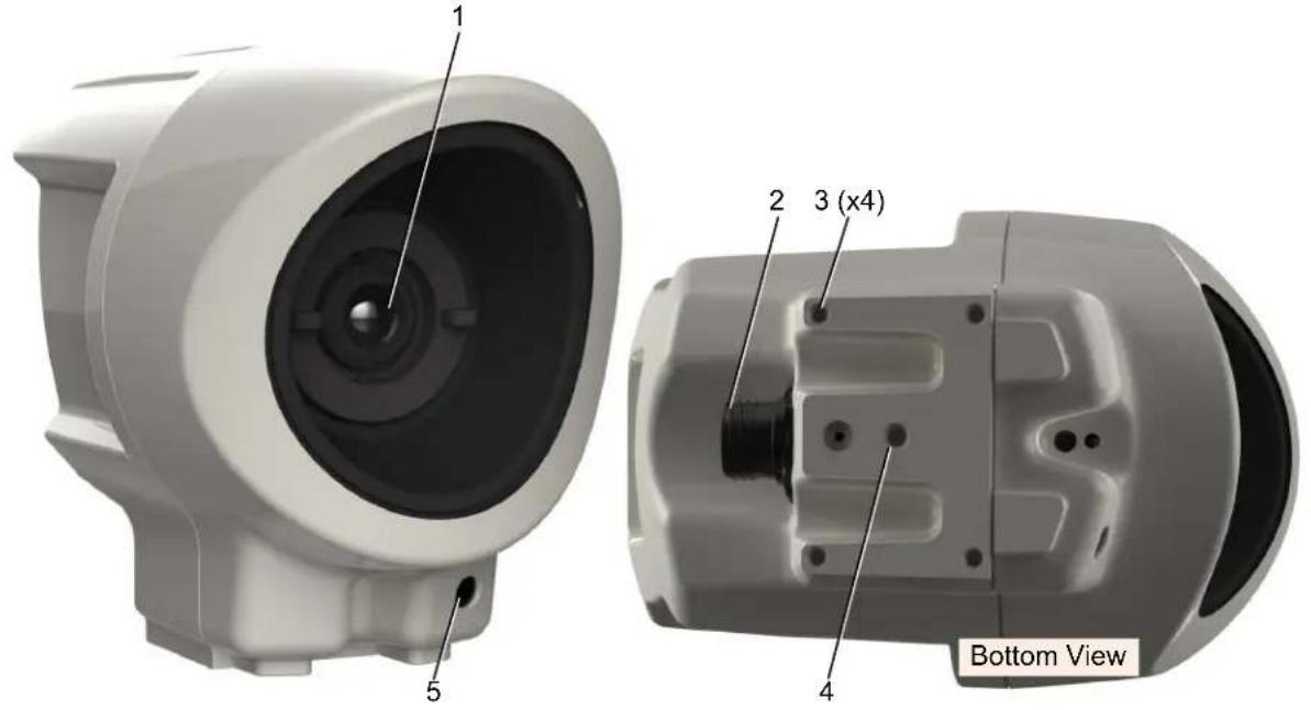
The Sarix TI Camera outer components include (see Figure 2-2):
- Infrared (IR) Camera Lens
- Main Connector (Power and Ethernet)
- Camera-to-Pole Mount Adapter fastening screws (x4)
-
Tripod mount fastening screw
-
Complementary Metal-Oxide Semiconductor (CMOS) Camera Lens (module depended).
Figure 2-2: Physical Description of the Camera
2.4 Marking
The camera us marked with a label as shown below:
Figure 2-3: Sarix TI Label

NOTE: For reference only
2.5 Sarix TI Web GUI
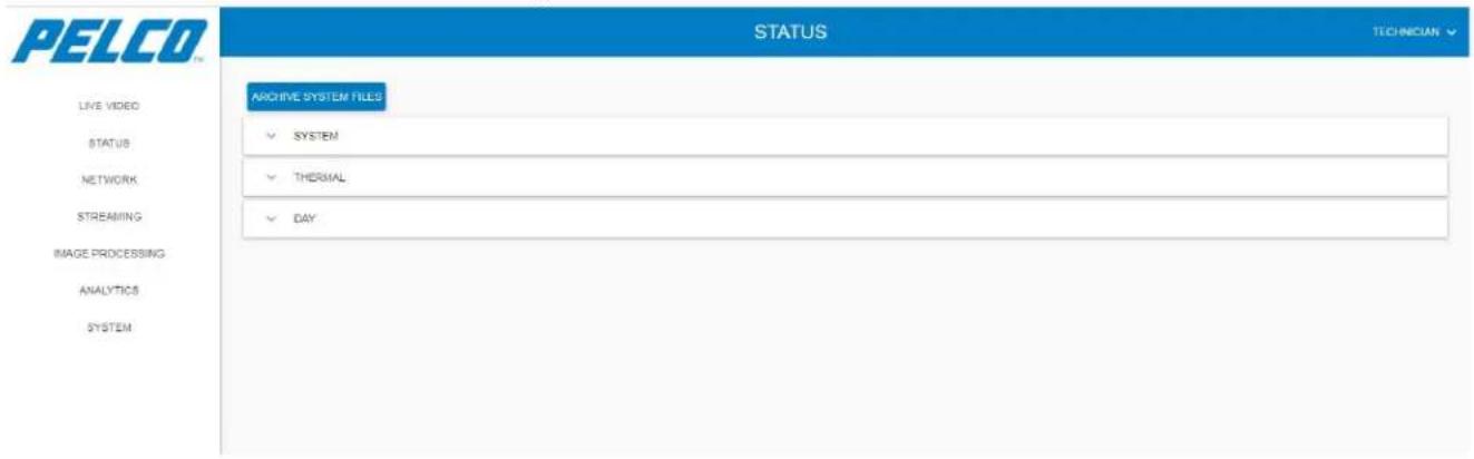
The operation of the Sarix TI Camera is performed via Web Graphical User Interface (GUI).
With the GUI you can:
➢ Setup the camera operation.
▶ Optimize the camera video.
Communicate with Video Management Systems (VMS).
Figure 2-4: Sarix TI Web GUI
2.6 Technical Data and Specifications
2.6.1 System Specifications
Applicable to models :Sarix TI 14.2mm, 35mm, and 50mm.
Table 2-1: Technical Data and Specifications - System Specifications
| Thermal Camera: | Imager Type: | Uncooled ASi Microbolometer |
| Spectral Band: 7.5 - | 14μ | |
| Pixel Size: 17μ | ||
| Resolution: 640 x 480 (VGA) or 384 x 288 (QVGA) | ||
| NETD: | VGA: < 40° mk, QVGA+: < 70° mk | |
| Day Camera: Imager Type: 1/4" CMOS | ||
| Resolutions: 640 x 480, 1024 x 768, or 1280 x 768 | ||
| Field of View: 54° (H) x 42° (V) @ 1024 x 768 | ||
| S/N Ratio: 36dB | ||
| Video: | Dual Channel: | 2 channels IP video |
| Compression: | H.264, Motion JPEG | |
| Frame Rate: | 8.3Hz or 25Hz | |
| Streaming: | RTSP, Unicast, Multicast | |
| Image Settings: | Brightness, Sharpness, Contrast, Rotation: 0°, 90°, 180°, 270° Horizontal and Vertical Flip | |
| Power Requirements: | Power Input: | 12 - 32VDC or Power over Ethernet (IEEE 802.3af/802.3at) |
| Consumption: | 7W typical, 20W max. (based on DC voltage) | |
| Environmental: | Storage Temp: | -40°C to +71°C (-40°F to +160°F) |
| Operating Temp: | -40°C to +55°C (-40°F to +131°F) | |
| Humidity: | +40°C, 95% RH | |
| Rating: IP66 (NEMA 4X equivalent) | ||
| Mechanical Parameters: | Dimensions: | - 135mm (w), 202mm (d), 169mm (h)- 5.32" (w), 7.95" (d), 6.65" (h) |
| Weight: | - 14 and 35mm: 2.2kg,- 50mm: 2.4kg, | |
| System Integration: | Interfaces: | ONVIF Profile S, Web GUI |
| Network: | Default IP: | 192.168.0.20 |
| RTSP Port: 8554 | ||
| Protocols: IPv4, HTTP, HTTPS, SSL/TLS, RTSP, DHCP | ||
| Certifications: - CE- FCC- IP66- UL and cUL | EN 55032:12;EN 55024:2010+A1:2015;EN 50130-4:11+A1:14;EN 61000-3-2:14;EN 61000-3-3:13;EN 60950-1:06+A11:09+A1:10+A12:11+A2:13UL 60950-1 2nd edition;CAN/CSA-C22.2 No. 60950-1:07+Amend 1:2011IEC 60950-1:05+A1:09+A2:13;IEC 60950-22:16 | |
2.6.2 Configurations
Table 2-2: Technical Data and Specifications - Configurations
| Day/Night Day | ||
| Configuration Type | Thermal Camera & Lens | Camera & Lens |
| VGA 17μ 640 x 480 AthermalizedUncooled Thermal | 14 " Colour HD CMOS 1280 x 720Autofocus | |
| QVGA+ 17μ 384 x 288 AthermalizedUncooled Thermal | ||
2.6.3 Thermal Camera
Table 2-3: Technical Data and Specifications - Thermal Camera
| Configuration TI2X14 TI2 | X35 TI2X | 50 | |
| Thermal Type Uncooled | |||
| Thermal Core 17μ 640 x 48 | 0 (VGA) or 17μ 384 x 288 (QVGA+) | ||
| Lens Type | Athermalized, Fixed Focus | ||
| Focal Length | 14.2mm | 35mm | 50mm |
| Lens F # f/1.2 f/1.2 | f/1.2 | ||
| Horizontal FOV - VGA | 42.1° | 17.6° | 12.4° |
| Horizontal FOV - QVGA+ | 25.7° | 10.6° | 7.5° |
| Video Type | H.264, Motion JPEG (25Hz or 9Hz) | ||
| Spectral Band | Spectral Band 7.5 - 14μ | ||
| NETD | < 40° mk (VGA), < 70° mk (QVGA+) | ||
| Digital Zoom | 1x, 2x, 4x | ||
| Control Operation | Polarity, NUC, Image Flip, Image Rotation & Digital Zoom | ||
2.6.4 CMOS Camera
Table 2-4: Technical Data and Specifications - CMOS Camera
| Imager Type: | 1/4" Colour HD CMOS |
| Effective Pixels / Resolutions: 640 x 480 or 1024 x 768 or 1280 x 720 | |
| Lens Type: | Autofocus |
| Imager FOV (H x V): | 54° x 42° |
| S/N Ratio: | 36dB |
| Additional Features: | Configurable Resolutions, Digital Zoom |
3. Safety
This chapter provides safety instructions that technicians should be aware of during the installation, operation and maintenance of the Sarix TI Series Camera.
The chapter consists of the following sections:
Section 3.1: Safety Conventions
Section 3.2: Safety During Installation
Section 3.3: Safety During Maintenance
3.1 Safety Conventions
In this manual, safety information is presented as warnings, cautions, and notes.
WARNING
An operating procedure, practice, and so forth, which if not correctly followed, could result in personal injury or loss of life.
CAUTION
An operating procedure, practice, and so forth, which if not strictly observed, could result in damage to, or destruction of equipment.
NOTE
An operating procedure, practice, and so forth that is essential to highlight.
All procedures in this manual must be performed in accordance with the applicable local regulations.
All local safety regulations apply. If the instructions in any section of this manual contradict those of the applicable local regulations, the instructions of the applicable local regulations will prevail.
3.2 Safety During Installation
To avoid injuries, follow standard safety regulations if mounting the Sarix TI Camera on an elevated location.
3.3 Safety During Maintenance
Warranty void if opening the Sarix TI camera.
Do not touch the Sarix TI Camera optics with bare hands.
Do not use any chemicals for cleaning the Sarix TI Camera. Use only wipes approved for optical equipment. Failure to comply could result in damage to the Sarix TI Camera optical-lens and/or its surfaces.
4. Installation
This chapter provides instructions for installing the Sarix TI Series Camera.
The chapter consists of the following sections:
Section 4.1: Unpacking
Section 4.2: Camera Installation
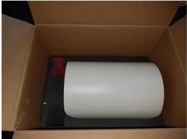
4.1 Unpacking
A standard package contains the following:
Sarix TI Camera
➢ 18-pin round female cable-connector
Ferrite
Washer Lock
Screw 6-32NCX1/4" SOC HD SS
Terminal lug ring 16AWG stub size 6
Package
Figure 4-1: Sarix TI Camera Package General View
natural_image
Interior view of a cardboard box containing a white cylindrical object placed on a black base, with a red partially visible part on the left (no text or symbols)4.2 Camera Installation
NOTE
Opening the Sarix TI Camera enclosure will void the product warranty.
CAUTION
Avoid pointing the Sarix TI Camera at the sun.
4.2.1 Installation Guidelines and Preparation
Prepare your self-made IP PoE cable (cables are available for purchase, see Table 7-3 for information).
4.2.1.1 Cable wires between camera and DC/PoE power supply should be 20-22AWG.
4.2.1.2 Both the camera ant the end-equipment connected to it should be permanently connected to protective earth, using screw and washers. Wires should be made of cupper. Minimal grounding cable is 14AWG.
4.2.1.3 In case of using DC power supply:
(1) The cables should be protected by fuse with maximal current of 3A
(2) The output current shall not exceed 3A after 60s
(3) The maximal output current of the power supply shall not exceed 7.5A
4.2.1.4 Power supply (either POE injector or DC power supply) should be safety approved for local regulations.
4.2.1.5 Install the Ferrite on the operational cable as close as possible, max 5cm, from the system.
4.2.2 Mechanical Interface Preparation
NOTE
It is recommended to check the functioning of the Sarix TI Camera prior to the actual installation.
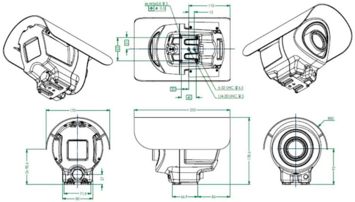
Figure 4-2 depicts the camera dimensions and mechanical interfaces.
Figure 4-2: Mechanical Interface Preparation - Camera Dimensions
4.2.3 Wall Mount Configuration
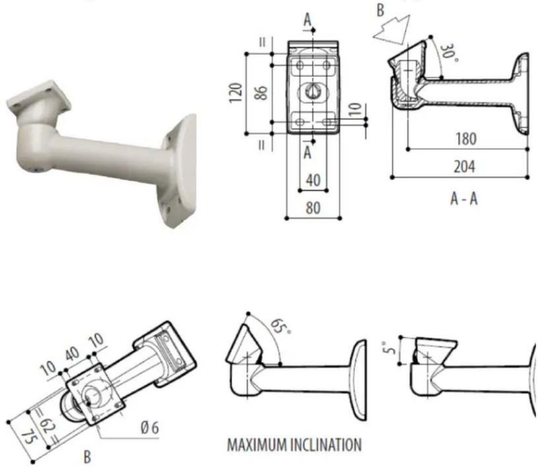
An arm for wall-mount is available for purchase (see Table 7-3 for information).
The dimensions of the arm are given in Figure 4-3:
Figure 4-3: Camera Installation - Wall Mount Configuration
4.2.4 Pole Mount Configuration
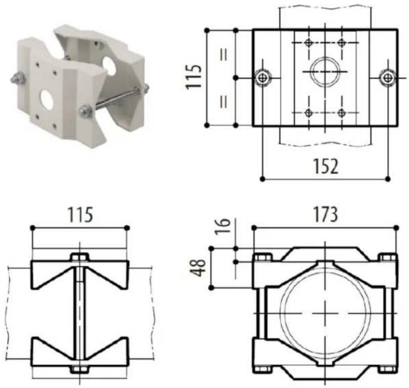
An adapter for pole-mount is available for purchase (see Table 7-3 for information).
The dimensions of the device are given in Figure 4-4 (note that the arm for wall-mount is required, as well):
Figure 4-4: Camera Installation - Pole Mount Configuration
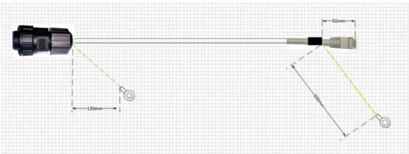
4.2.5 Electrical ICD IP PoE Cable
The cable is available for purchase (see Table 7-3 for information).
Cable Pinout (see Figure 4-5):
Table 4-1: Electrical ICD IP PoE Cable - Pinout
| Connector Pin # P1 | Connector Pin # P2 (RJ45) | Signal Name | |
| Ethernet\POE | 2 | 1 | ETH RX+ |
| 6 | 2 | ETH RX- | |
| 11 | 3 | ETH TX+ | |
| 15 | 6 | ETH TX- | |
| 12 | 5,4 | POE + | |
| 14 | 7,8 | POE - | |
| DC Power Input | 8 | P.S (-) | 12-32vDC RTN |
| 9 | P.S (+) | 12-32vDC | |
| Shield | Camera body | GND Stud | Shield |
Figure 4-5: Electrical ICD IP PoE Cable
5. Operation
This chapter provides operating instructions for the Sarix TI Series Camera web GUI.
The chapter consists of the following sections:
Section 5.1: First Time Credentials Setup
Section 5.2: Logging Into Sarix TI Camera Web GUI
Section 5.3: Changing Your Password
Section 5.4: Main Window Overview
Section 5.5: Live View Window
Section 5.6: Status Window
Section 5.7: Network Window
Section 5.8: Streaming Window
Section 5.9: Image Processing Window
Section 5.10: Analytics Window
Section 5.11: System Window
Section 5.12: Logging Out from the Web GUI
5.1 First Time Credentials Setup
- Open your web browser.
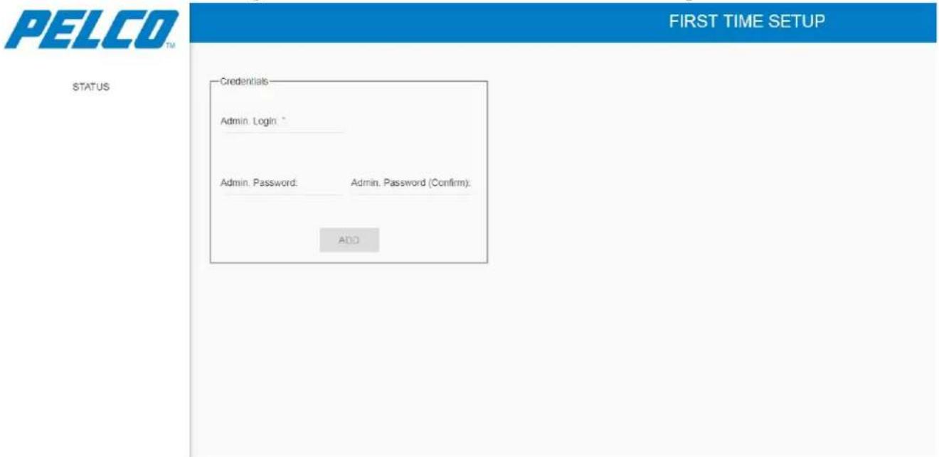
- Type the Sarix TI Camera default IP address (192.168.0.20) in the address bar and click Enter. The First Time Setup window opens (example):
Figure 5-1: Sarix TI Web GUI – First Time Setup
NOTE
The First Time Setup window appears the first time a user accesses the camera's IP address.
- Define the administrator username in the Admin Login section.
- Define the administrator password in the Admin Password section.
- Retype the same password in the Admin Password (confirm) section.
- Click ADD. The administrator credentials are defined.
NOTE
After defining the administrator credentials, the Status window opens (see Section 5.2).
5.2 Logging Into Sarix TI Camera Web GUI
-
Open your web browser.
-
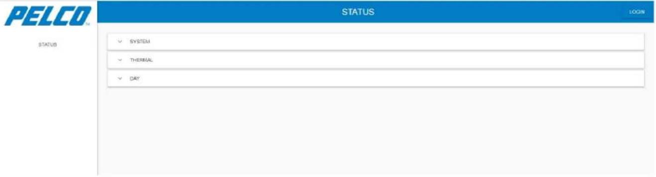
Type the Sarix TI Camera default IP address (192.168.0.20) in the address bar and click Enter. The Status window opens (example):
Figure 5-2: Sarix TI Web GUI - Status Window (before Login)
-
You may now view some default settings of your Sarix TI Camera by expanding the System, Thermal or Day tabs.
-
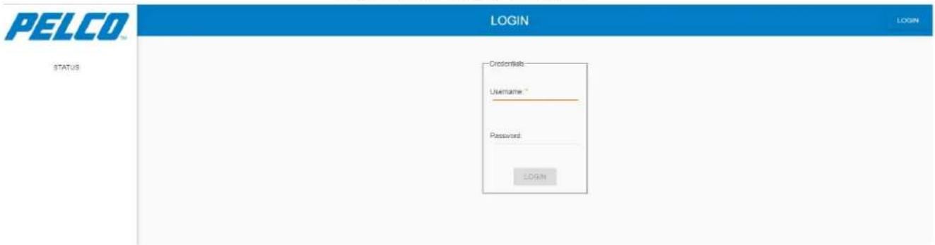
Click . The Login window opens:
Figure 5-3: Login Window
NOTE
A user is able to login only after they set up their credentials for the first time (see Section 5.1).
5. Enter your Username and Password:
Figure 5-4: Login Window – Entering Username and Password
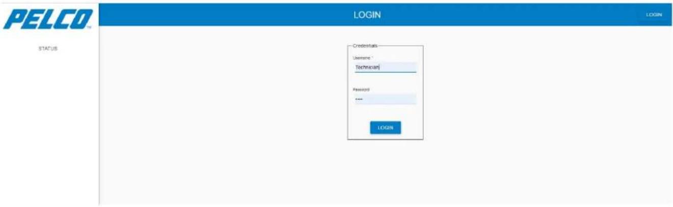
- Click LOGIN. The following message is displayed on the lower-left corner of the screen for three seconds, stating that you have successfully logged in. In addition, the Status window opens:

Figure 5-5: Sarix TI Web GUI - Status Window (after Login)
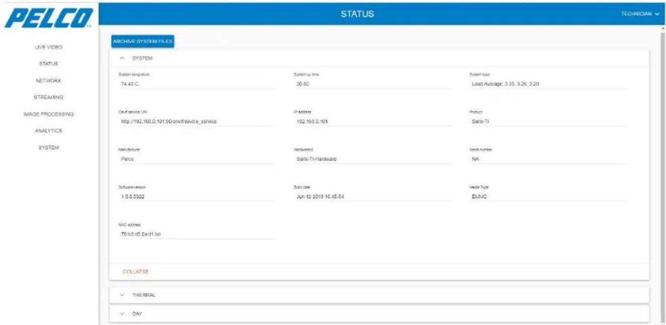
You can now use the Sarix TI Web GUI.
5.3 Changing Your Password
- From the upper-right drop-down menu select Change Password:
Figure 5-6: Changing Your Password - Drop Down Menu
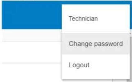
The following opens:
Figure 5-7: Sarix TI Web GUI - Changing Your Password
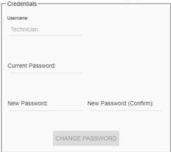
- Enter your Current Password.
- Enter the New Password and re-enter in the New Password (Confirm) field.
- Click CHANGE PASSWORD. The system automatically logs out and the Login window reopen (see Figure 5-3).
- Log in using the new password. The Status window re-opens (see Figure 5-5).
5.4 Main Window Overview
The main areas in every window consist of the following:
Figure 5-8: Main Window Overview - Main Areas
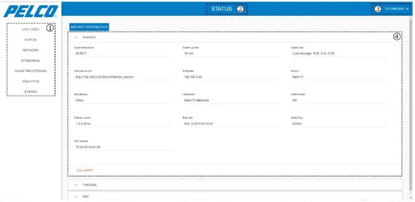
Legend:
- Menu: maneuvering between the GUI main features/tabs.
- The name of the currently opened feature/tab.
- Available only after logging in; a drop-down menu, enables to change your password or log out from the program.
- The area where you can view and/or set the feature parameters.
5.5 Live View Window
The Live View window allows viewing the Sarix TI Camera live video.
- Click Live View. The Live View window opens, containing a live video display of both thermal and visual cameras (example):
Figure 5-9: Live View Window (example)
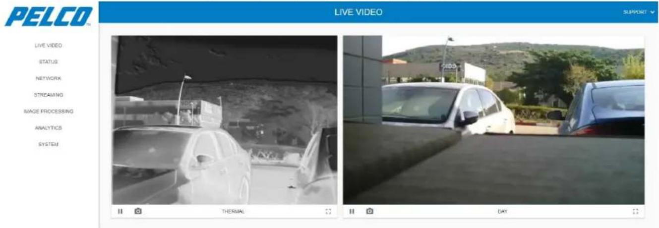
-
To freeze the live-view video click □. Click ▶ to resume the live-view video.
-
To view the video in full screen click [.] Click the keyboard Esc key to resume.
-
To take a snapshot of the video and save elsewhere:
a. Click 📄 . A *.jpg file is created and downloaded into your PC. The file is saved in your \Downloads folder.
- the file name of the thermal camera snapshot: proxycam-ir-Snapshot.
- the file name of the visual camera snapshot: proxycam-vis-Snapshot.
b. You can now move the file elsewhere.
5.6 Status Window
The Status window allows viewing some of the Sarix TI Camera parameters and settings.
- Click Status. The Status window opens (all collapsed):
Figure 5-10: Status Window (all collapsed)
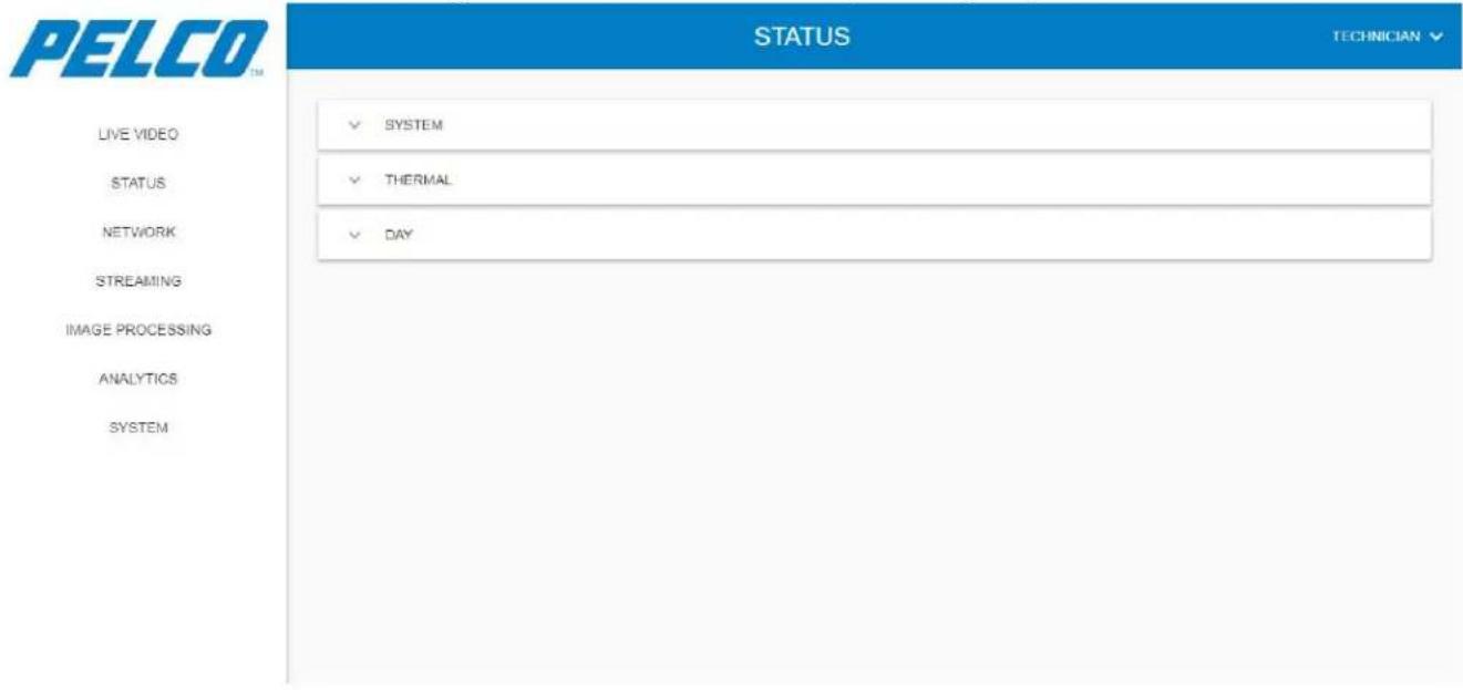
The Status window is comprised of three tabs:
System Tab: allows viewing general parameters related to the camera settings and its software/firmware (see Section 5.6.1).
Thermal Tab: allows viewing parameters related to the thermal camera settings and its software/firmware (see Section 5.6.2).
Day Tab: allows viewing parameters related to the visual camera settings and its software/firmware (see Section 5.6.3).
➢ Disabling / Enabling a Camera: allows disabling the thermal camera and/or the visual camera and enable them (see Section 5.6.4).
5.6.1 System Tab
The System tab allows viewing general parameters related to the camera settings and its software/firmware.
Expand the System tab. The following opens:
Figure 5-11: Status Window - System Tab
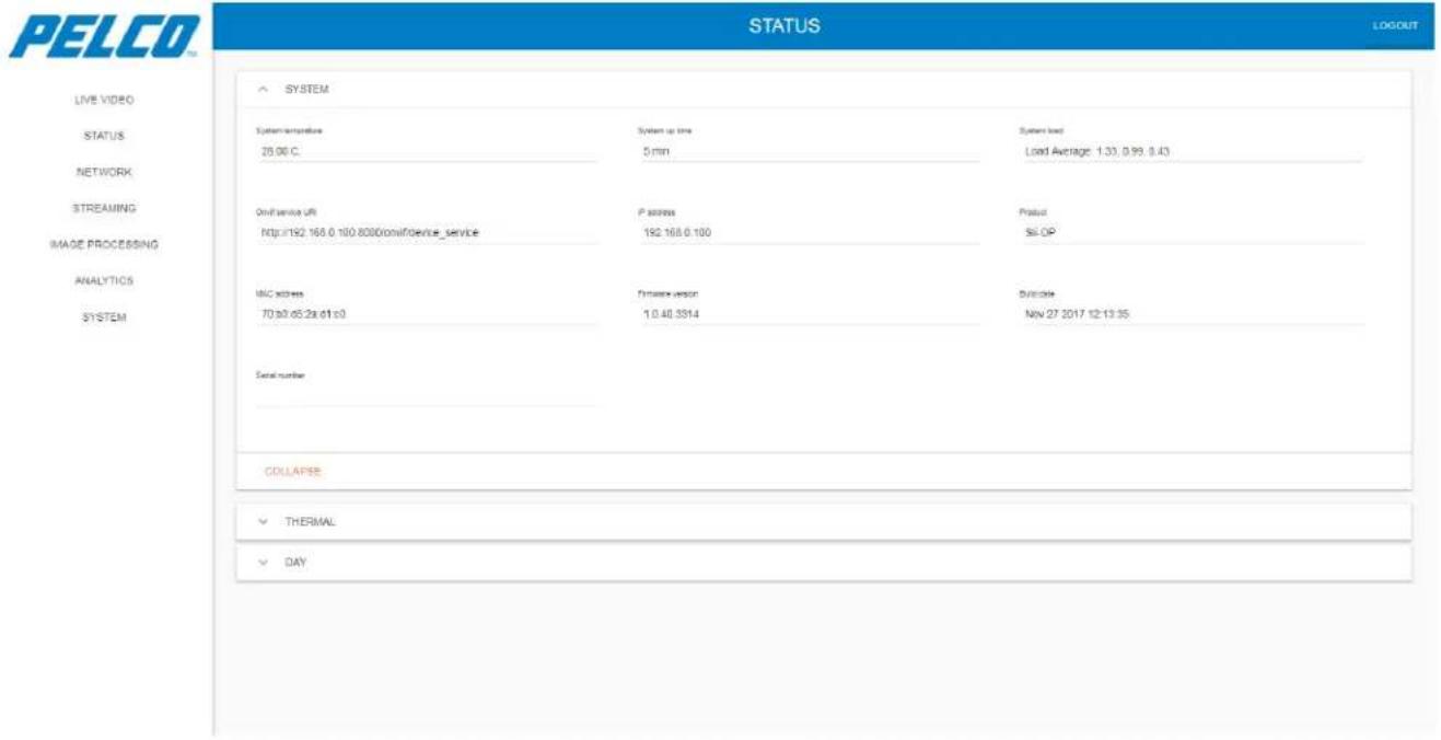
The System tab consists of the following parameters:
System temperature: the "System On Chip" temperature.
System up time: the operating time since the last camera startup.
System load: a coded indication on how the system is busy.
ONVIF service URI: the Uniform Resource Indicator (URI), e.g., the ONVIF device web service address.
IP address: the camera IP address.
Product: the camera name.
Serial number: the system Serial Number (S/N).
➢ Firmware version: the version of the installed Firmware (FM).
Build date: the date of the FM creation.
MAC address: the camera unique Media Access Control (MAC) address.
5.6.2 Thermal Tab
The Thermal tab allows viewing parameters related to the thermal camera settings and its software/firmware.
Expand the Thermal tab. The following opens:
Figure 5-12: Status Window - Thermal Tab
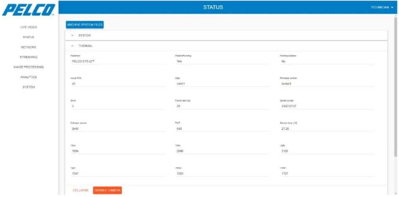
The Thermal tab consists of the following parameters:
Pipeline ID: the current name of the pipeline (data processing elements, connected in series, where the output of one element is the input of the next one).
▶ Pipeline Running: is the pipeline running?
➢ Pending Updates: does the pipeline requires initialization?
➢ Actual FPS: the current frame-rate where the pipeline is running.
DFPA: indication from the thermal camera.
➢ Firmware version: indication from the thermal camera.
Gain: indication from the thermal camera.
Frame rate [Hz]: indication from the thermal camera.
Serial number: indication from the thermal camera.
Software version: indication from the thermal camera.
➢ TINT: indication from the thermal camera.
➢ Sensor temp [°C]: indication from the thermal camera.
➢ V bus: indication from the thermal camera.
➢ VDDA: indication from the thermal camera.
➢ VGFID: indication from the thermal camera.
➢ VGSK: indication from the thermal camera.
VT bias: indication from the thermal camera.
➢ VTOFS1: indication from the thermal camera.
➢ VTOFS2: indication from the thermal camera.
5.6.3 Day Tab
The Day tab allows viewing parameters related to the thermal camera settings and its software/firmware.
Expand the Day tab. The following opens:
Figure 5-13: Status Window - Day Tab
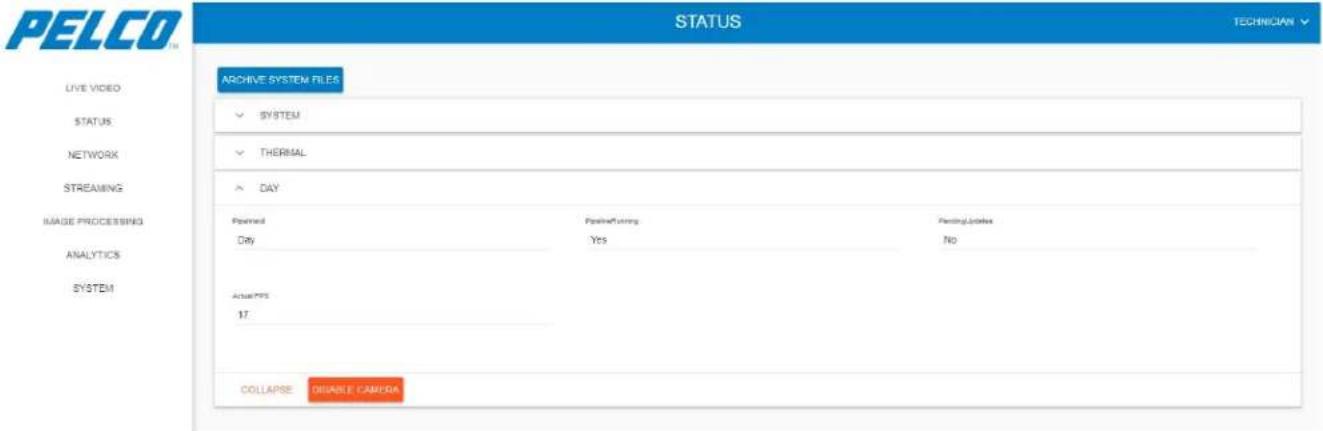
The Day tab consists of the following parameters:
▶ Pipeline ID: the current name of the pipeline.
▶ Pipeline Running: is the pipeline running?
➢ Pending Updates: does the pipeline requires initialization?
➢ Actual FPS: the current frame-rate where the pipeline is running.
5.6.4 Disabling / Enabling a Camera
This option allows to disable the thermal camera and/or the CMOS camera and re-enable them.
5.6.4.1 Disabling the Camera
- Expand the Thermal / Day tab and click . The following opens:
Are you sure you want to disable camera?
System will automatically restart for changes to take effect.
CANCEL
OK
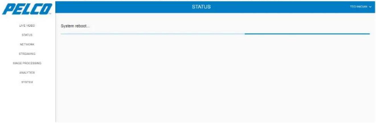
- Click OK to approve. The following opens while the system re-boots:
Figure 5-14: Disabling / Enabling a Camera - System Reboot
On completion, the following opens stating that the corresponding camera is disabled:
Figure 5-15: Disabling / Enabling a Camera - System Reboot Approval
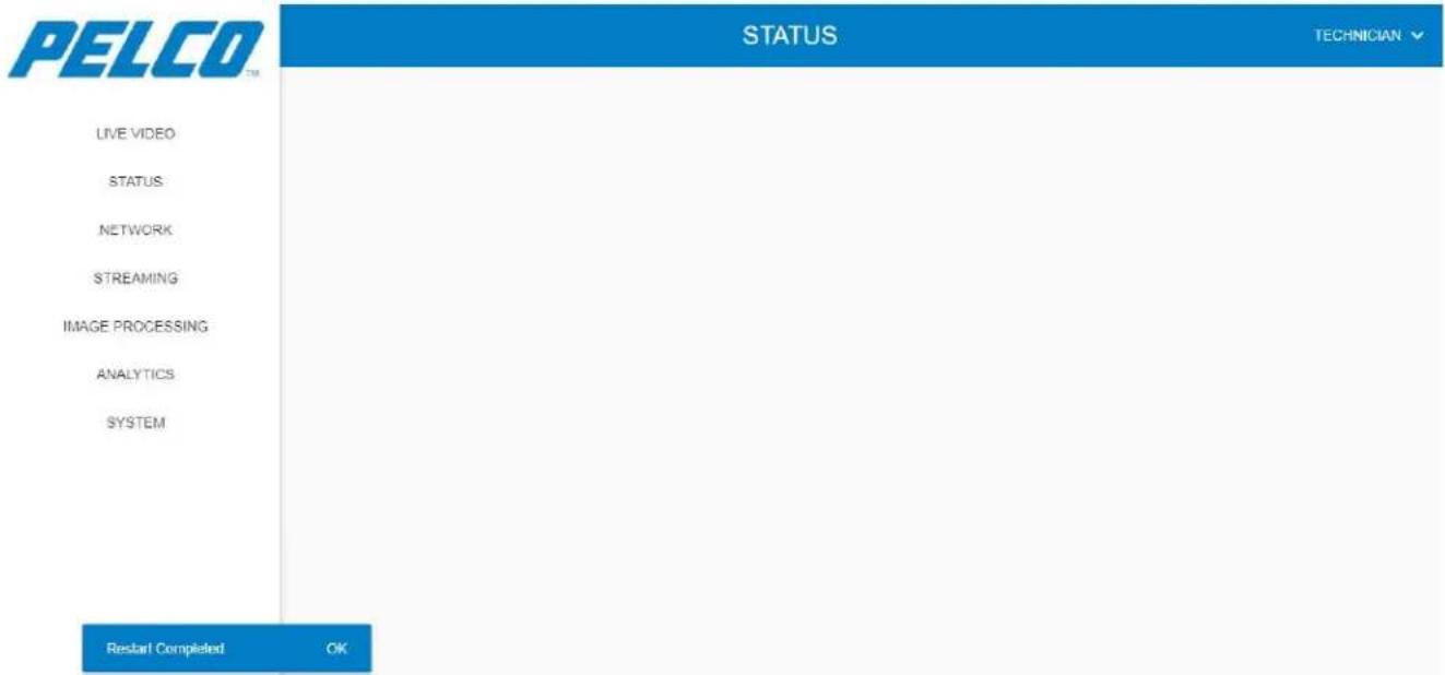
The camera view does not appear anymore on the Live View window.
5.6.4.2 Enabling the Camera
- Expand the Thermal / Day tab and click . The following opens:
Are you sure you want to enable camera?
System will automatically restart for changes to take effect.
CANCEL
OK
- Click OK to approve. The system re-boots (see Figure 5-14).
On completion, a message is displayed stating that the system has restarted (see Figure 5-15).
The camera view is now available on the Live View window.
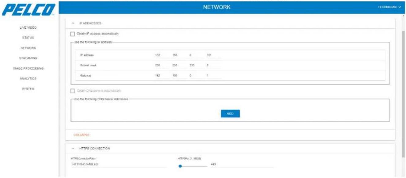
5.7 Network Window
The Network window allows configuring the HOST-to-Camera Ethernet communication method.
- Click Network. The Ethernet window - Basic Settings tab opens:
Figure 5-16: Network Window - Basic Settings Tab
5.7.1 Setting of IP Address
To change the IP address, Subnet mask or Gateway values:
- Click on the corresponding address and change the value either using the button or type the IP address using the keyboard. An example is shown in Figure 5-17:
Figure 5-17: Network Window - Changing an Address
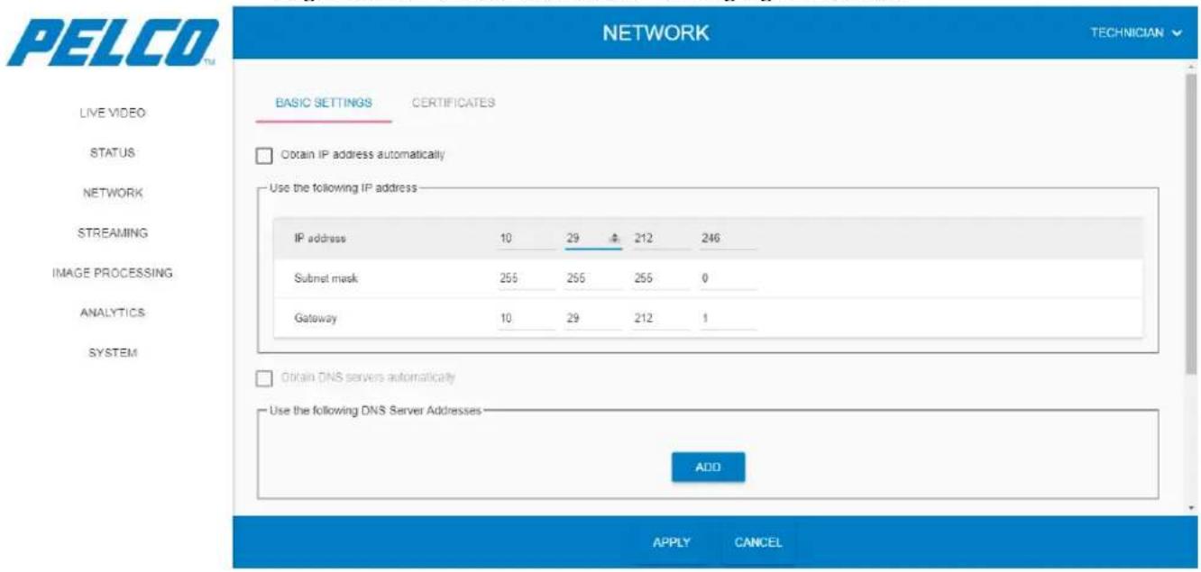
- Click APPLY for the changes to take effect (click CANCEL to revert your changes).
5.7.2 Setting an Auto IP Address (DHCP)
To set a dynamically assigned IP address:
- Select the Obtain IP address automatically checkbox. Results:
- The address area turns invalid.
- the DNS area become valid.
- To let the system to select an auto DNS server address: enable the DNS area by selecting the Obtain IP address automatically checkbox. The Obtain DNS servers automatically checkbox is automatically selected.
- Click APPLY for the changes to take effect (click CANCEL to revert your changes).
5.7.3 Setting a Manual DNS Server Address
This option is applicable when you wish to synchronize the time and date with a DNS server (see Section 5.11.3.2).
To manually select a DNS server address:
- Enable the DNS area by selecting the Obtain IP address automatically checkbox. The Obtain DNS servers automatically checkbox is automatically selected.
- Clear the Obtain DNS servers automatically checkbox.
- Click . An empty DNS line is added.
- Determine the address.
- Click APPLY for the changes to take effect (click CANCEL to revert your changes).
5.7.4 Settings of HTTPS Connection
This option is applicable when selecting either a self-signed certificate or uploading an existing certificate (see Section 5.7.7).
To set the HTTPS connection:
- Set the HTTPS Port bar to the required value (1 to 65535).
- Click APPLY for the changes to take effect (click CANCEL to revert your changes).
5.7.5 Setting the Network Interface
To have the network interface permanently set to 100 Mbps:
- Select the Advanced tab. The following opens:
Figure 5-18: Network Window - Setting Network Interface
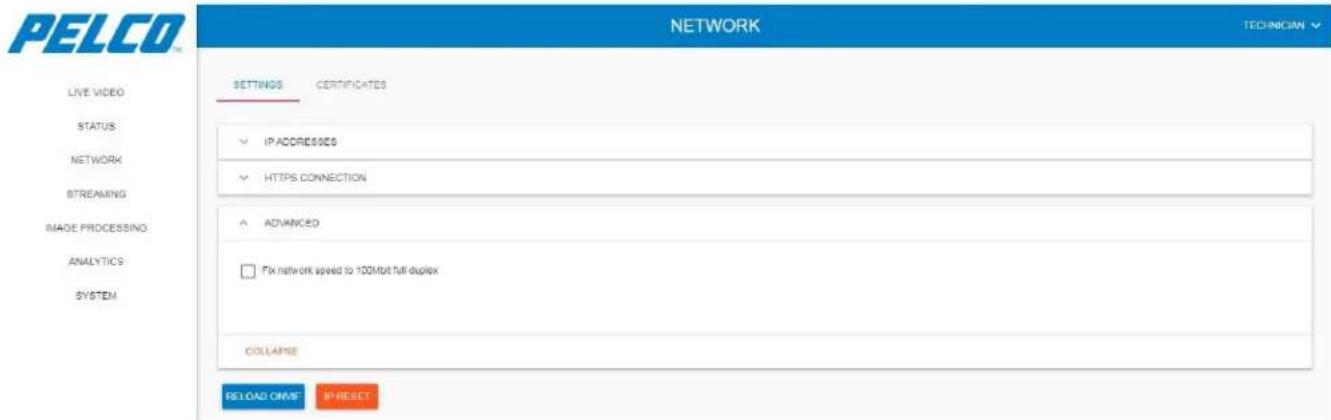
- Select the Fix network speed to 100Mbit full duplex checkbox.
5.7.6 Resetting Network Settings
To revert network settings back to factory defaults:
- Click . The following opens:
Figure 5-19: Network Window - Resetting IP Address Approval
Are you sure you want to revert network settings to factory defaults?
This will undo all previous network settings
CANCEL
OK
- Click OK to revert network settings back to factory defaults.
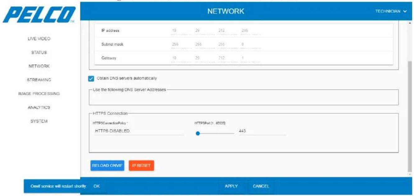
5.7.7 Restarting ONVIF Service
To restart the system and reload ONVIF service:
Click . The following opens while the system re-starts:
Figure 5-20: Network Window - ONVIF Reload
NOTE
The HTTPS Port default value is 443.
5.7.8 Certificates
5.7.8.1 Creating a Certificate Request
This option allows retrieval of a Secure Sockets Layer (SSL) certificate.
- Select the Certificates tab. The following opens:
Figure 5-21: Certificates - Creating a Certificate Request
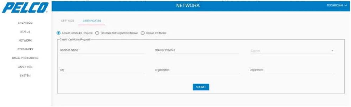
-
Enter/select the following details:
-
Common Name (compulsory; an IP address or system Host name).
• State or Province
• Country (select from the drop-down list) - City
- Organization
-
Department
-
Click SUBMIT. Your request is submitted for approvals.
5.7.8.2 Generating a Self-Signed Certificate
This option allows producing a self-made certificate.
- Select the Generate Self-Signed Certificate option. The following opens:
Figure 5-22: Certificates - Generating a Self-Signed Certificate
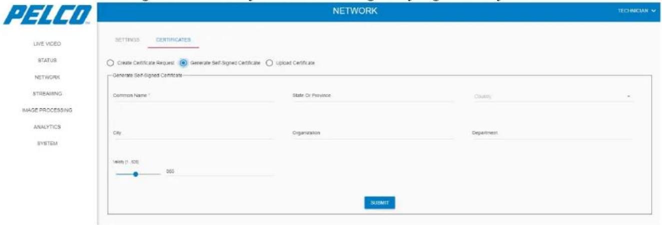
-
Enter/select the following details:
-
Common Name (compulsory; an IP address or system Host name).
• State or Province
• Country (select from the drop-down list) - City
- Organization
- Department
-
Validity (in days)
-
Click SUBMIT. Your self-signed certificate is submitted for approvals.
5.7.8.3 Uploading a Certificate
This option allows loading an existing certificate, originated by another source.
- Select the Upload Certificate option. The following opens:
Figure 5-23: Certificates - Uploading a Certificate
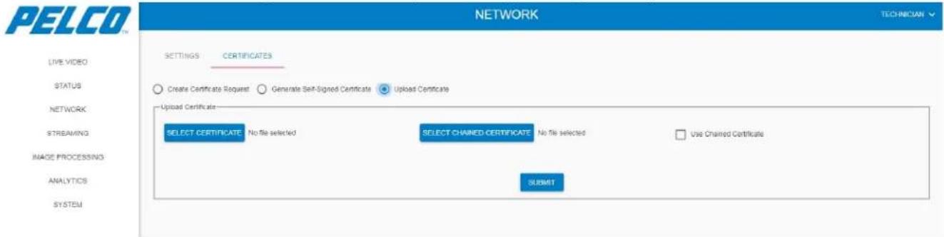
- Click SELECT FILE and browse to select the certificate file (*.pem format).
- Click . Your uploaded certificate is submitted.
5.8 Streaming Window
The Streaming window allows configuring the video flow-rate and the video encoding method.
5.8.1 Thermal Tab
- Click Streaming. The Streaming - Thermal Tab opens:
Figure 5-24: Streaming Window - Thermal Tab
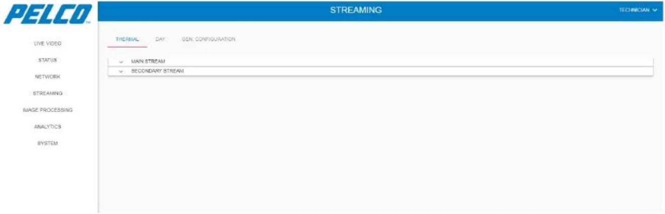
-
Under each option in the Thermal Tab you can:
-
Click to restart the video streaming.
- Click to stop the video streaming.
- Click to re-start the video streaming.
5.8.1.1 Main Stream
Expand the Main Stream option. The following opens (click APPLY for the changes to take effect; click CANCEL to revert your changes):
Figure 5-25: Streaming Window - Thermal Tab - Main Stream
![PELCO STREAMING TECHNICIAN LIVE VIDEO STATUS NETWORK STREAMING IMAGE PROCESSING ANALYTICS SYSTEM THERMAL DAY GEN CONFIGURATION MAIN STREAM STREAM URL: http://192.168.0.101.8554/1927 MISCL PROPERTIES CBR (Napel) [04, 1034] 2900 Pare Controls CBR Video encoding N264 Multicast Multicast/RTPPol [024, 1033] Image sources GRAY16 [0.0.640.480] @ 25.00 H2 Multicast/RTPPol [024, 1033] 1254 VSP quality factor [1, 04] 60 Unit Type Stationary Wide MULTICAST Multicast/RTPPol [024, 1033] Multicast/RTPPol [024, 1033] 239 209 42 42 SECONDARY STREAM APPLY CANCEL](/content/2026/06/1147139/images/3ba546536c5d5dbee61757e40a10bb82bcaa3e9b5d33fc1188721ae54f9ca466.jpg)
The main stream option consists of the following parameters:
➢ Misc Properties parameters:
• CBR: the video flow-rate (Kb/Sec).
- IntraQp: an auto calculation of the I-level quality-level (default: -1).
• VBR quality factor: 1 is the lowest level (applies only for VBR).
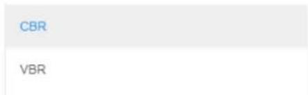
• Rate Control: Constant Bit Rate (CBR) or Variable Bit Rate (VBR).
• GOP: Group Of Pictures; how many frames will include an Intra-Frame.
- Unit Type: selection of the installed camera/lens type and the installation method.
![VBR quality factor [1 , 64] Moving PTZ StationaryWide StationaryMediumRange StationaryLongRange](/content/2026/06/1147139/images/d7743981868974f9bf62242d3435b3d955ee1b68b4a7aa66e74148a118ed6f4e.jpg)
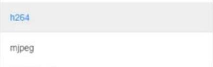
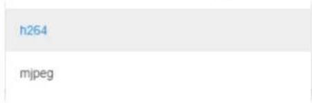
• Video Encoding: selection of the video coding (mjpeg requires a system restart).
• Image Size/Rate: selection of the video that will be taken from the camera.
![UYVY [0,0,1280,720] @ 12.50 HZ UYVY [0,0,1280,720] @ 15.00 HZ UYVY [0,0,1280,720] @ 25.00 HZ UYVY [0,0,1280,720] @ 30.00 HZ](/content/2026/06/1147139/images/49adb249c965459fc53c20de310bdfb2604d80a6b09bfc00504550d29aed59c2.jpg)
5.8.1.2 Secondary Stream
Expand the Secondary Stream option. The following opens (click APPLY for the changes to take effect; click CANCEL to revert your changes):
Figure 5-26: Streaming Window - Thermal Tab - Secondary Stream
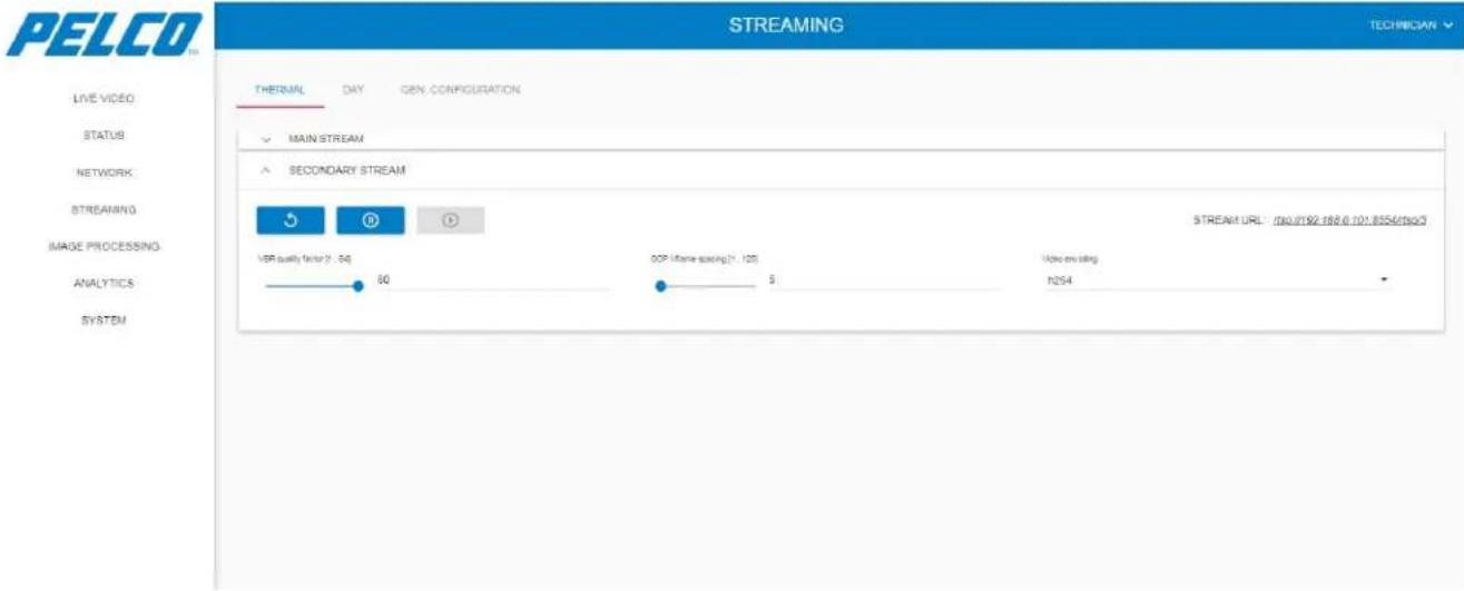
The secondary stream option consists of the following parameters:
➢ VBR quality factor: 1 is the lowest level.
GOP I-frame spacing: Group Of Pictures; how many frames will include an Intra-Frame.
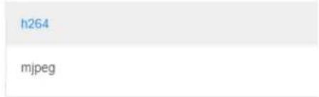
➢ Video encoding: selection of the video coding (mjpeg requires a system restart).
5.8.2 Day Tab
Under each option in the Day Tab you can:
- Click to restart the video streaming.
- Click to stop the video streaming.
- Click to re-start the video streaming.
5.8.2.1 Main Stream
Expand the Main Stream option. The following opens (click APPLY for the changes to take effect; click CANCEL to revert your changes):
Figure 5-27: Streaming Window - Day Tab - Main Stream
![PELCO STREAMING TECHNICIAN THERMAL DAY GEN CONFIGURATION MAIN STREAM GDR (Base) [64, 10384] 64 inline (+, 5) -1 VBR quality factor [1, 64] 60 Rate Control VBR GDP User spacing (1, 120) 2 UnitType Stationary Wide Video Scale No Change Video encoding 1064 Image attribute LVYY [0,0.1260.720] @ 25.00 kHz SECONDARY STREAM APPLY CANCEL STREAM URL: http://92.158.0.101.855/1962](/content/2026/06/1147139/images/e5a6b8077309b447a21a276094129afc2c4314e75f55e0bacef27136eb4e80c4.jpg)
The main stream option consists of the following parameters:
• CBR: the video flow-rate (Kb/Sec).
- IntraQp: an auto calculation of the I-level quality-level (default: -1).
• VBR quality factor: 1 is the lowest level (applies only for VBR).
• Rate Control: CBR or VBR.
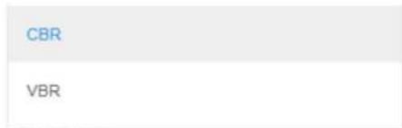
• GOP: Group Of Pictures; how many frames will include an Intra-Frame.
- Unit Type: selection of the installed camera/lens type and the installation method.
![VBR quality factor [1, 64] Moving PTZ StationaryWide StationaryMediumRange StationaryLongRange](/content/2026/06/1147139/images/c8d0772d4fe02e61e186cd6600844a936840cc5068dde8b34cdafae2119e0d04.jpg)
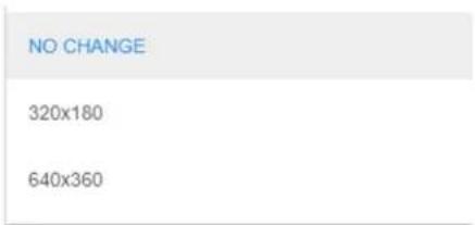
• Video Scale: the video resolution; "NO CHANGE": 1280 x 720 (HD).
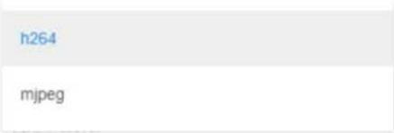
• Video Encoding: selection of the video coding (mjpeg requires a system restart).
• Image Size/Rate: selection of the video that will be taken from the camera.
![GRAY16 [0,0,640,480] @ 25.00 HZ GRAY16 [128,96,384,288] @ 25.00 HZ GRAY16 [160,120,320,240] @ 25.00 HZ GRAY16 [224,168,192,144] @ 25.00 HZ](/content/2026/06/1147139/images/2283462fbce737b2e5380a4521016d234d31e931ab87c43dc77e2c0f6db4945b.jpg)
5.8.2.2 Secondary Stream
Expand the Secondary Stream option. The following opens (click APPLY for the changes to take effect; click CANCEL to revert your changes):
Figure 5-28: Streaming Window - Day Tab - Secondary Stream
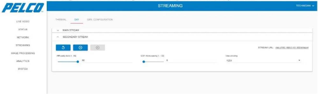
The secondary stream option consists of the following parameters:
➢ VBR quality factor: 1 is the lowest level.
GOP I-frame spacing: Group Of Pictures; how many frames will include an Intra-Frame.
➢ Video encoding: selection of the video coding (mjpeg requires a system restart).
5.8.3 General Configuration Tab
Select the General Configuration tab. The following opens (click APPLY for the changes to take effect; click CANCEL to revert your changes):
Figure 5-29: Streaming Window - General Configuration Tab
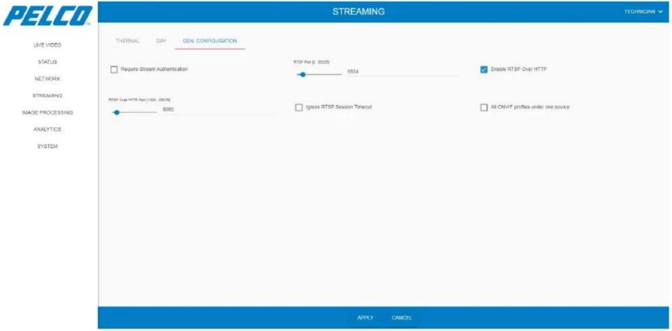
The General Configuration tab consists of the following parameters:
➢ Enable Authentication: user/password enabled.
▶ RTSP Port: the RTSP port.
▶ RTSP Over HTTP Enabled
▶ RTSP Over HTTP Port
5.9 Image Processing Window
The Image Processing window allows changing the video display method, orientation and quality.
Click Image Processing. The Image Processing - Thermal tab opens.
5.9.1 Thermal Tab
1. You can:
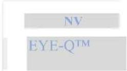
- From the Active Pipeline drop-down list select the pipeline name that is currently active (either Night Vision - NV or EyeQ):
- Click to restart the video streaming.
- Click to stop the video streaming.
- Click to re-start the video streaming.
Figure 5-30: Image Processing Window - Thermal Tab
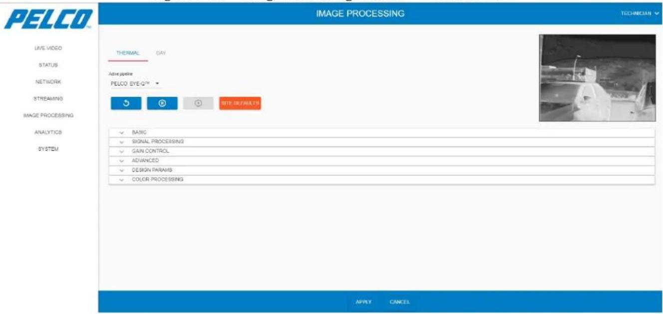
- Applicable for video processing only: click SITE DEFAULTS to revert the entire settings to your local site settings. The following opens:
Are you sure you want to revert settings to site defaults?
This will undo all previous settings
CANCEL OK
-
Click OK to approve.
-
Click APPLY for the changes to take effect (click CANCEL to revert your changes).
5.9.1.1 Basic Settings
Expand the Basic Settings option. The following opens (click APPLY for the changes to take effect; click CANCEL to revert your changes):
Figure 5-31: Image Processing Window - Thermal Tab - Basic Settings
![PELCO TM IMAGE PROCESSING TECHNICIAN LIVE VIDEO STATUS NETWORK STREAMING IMAGE PROCESSING ANALYTICS SYSTEM THERMAL DAY Active pipeline PELCO EYE-Q™ SITE DEFAULTS BASIC Black hot Gamma [0.5, 3] 1 SIGNAL PROCESSING GAIN CONTROL APPLY CANCEL](/content/2026/06/1147139/images/072e3c00aabfd770e1d467a7c50271d03d531fb897e2e5e1f81e976de671ba12.jpg)
The Basic Settings option consists of the following parameters:
Black hot: select ("Black Hot") or Clear ("White Hot") the Black Hot checkbox. After clicking APPLY, the video image display is changing accordingly (example):
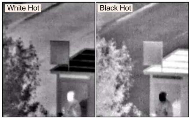
➢ Gamma: Gamma level corrections.
5.9.1.2 Signal Processing Settings
- Expand the Basic Settings option. The following opens (click APPLY for the changes to take effect; click CANCEL to revert your changes):
Figure 5-32: Image Processing Window - Thermal Tab - Signal Processing Settings
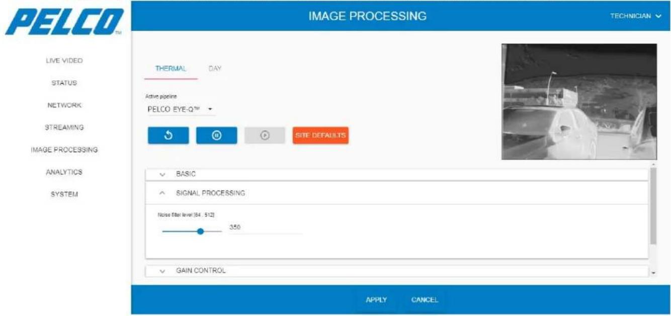
- Set the Noise filter level: filtering noises. It is recommended to remain with the default value (high-value filtering will result in movement smudge).
5.9.1.3 Gain Control Settings
Expand the Gain Control option. The following opens (click APPLY for the changes to take effect; click CANCEL to revert your changes):
Figure 5-33: Image Processing Window - Thermal Tab - Gain Control Settings
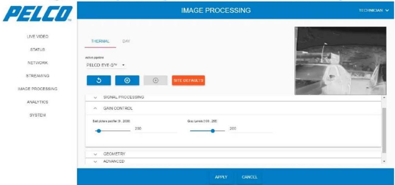
The Gain Control option consists of the following parameters:
Bad picture pacifier: noise-level deductions. It is recommended to remain with the default value.
Gray Levels: the quantity of the gray-levels (up to 200).
5.9.1.4 Advanced Settings
Expand the Advanced Settings option. The following opens (click APPLY for the changes to take effect; click CANCEL to revert your changes):
Figure 5-34: Image Processing Window - Thermal Tab - Advanced Settings
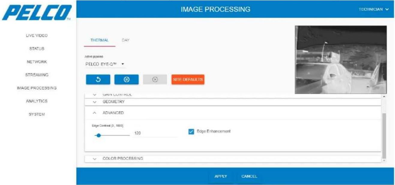
The Advanced Settings option consists of the following parameters:
Edge Contrast: enhancement of the image contrast.
Edge Enhancement: enhancement of the image edges.
5.9.1.5 Color Processing Settings
- Expand the Color Processing option. The following opens (click APPLY for the changes to take effect; click CANCEL to revert your changes):
Figure 5-35: Image Processing Window - Thermal Tab - Color Processing Settings
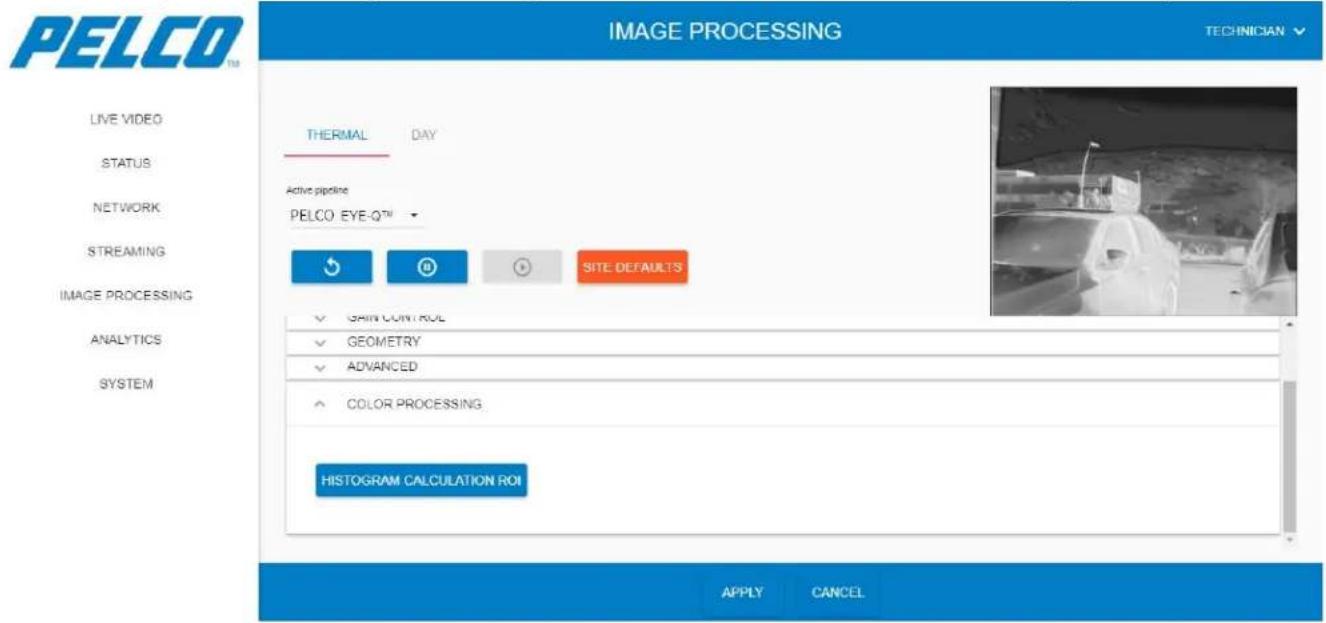
- Click HISTOGRAM CALCULATION ROI. The following opens (example):
Figure 5-36: Image Processing Window - Histogram Calculation ROI (1 of 3)
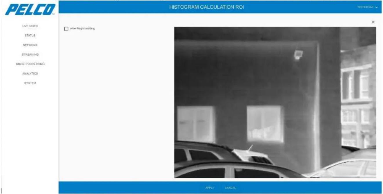
-
Select the Allow Region Editing checkbox allowing to define an ROI on the image. The Regions and Sub-Regions areas are enabled.
-
Click the + sign to enable more than one sub-region.
-
Select SubRegion-1 and mark an ROI on the image using the mouse (example):
Figure 5-37: Image Processing Window - Histogram Calculation ROI (2 of 3)
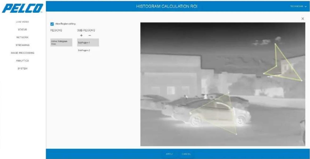
-
Click APPLY. The Sub Region area is highlighted on the image and the histogram is automatically calculated and saved (the image processing only focuses on the pixels on the pixels within the ROI).
-
If more than one SubRegion is defined: select SubRegion-2 and mark an ROI on the image using the mouse (example):
Figure 5-38: Image Processing Window - Histogram Calculation ROI (3 of 3)
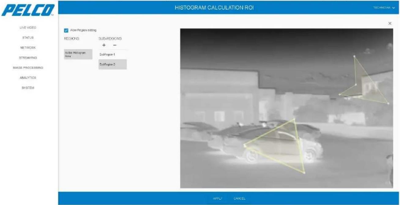
- Click Active Histogram Area to define the selected area as the reference for the calculation.
- Click APPLY. The Sub Region area is highlighted on the image and the histogram is automatically calculated and saved.
- To delete a Sub Region definitions: select the Sub Region (SubRegion-1 or SubRegion-2 in the example) and click the - sign.
- Clear the Allow Region Editing checkbox. The image is cleared from the ROI markings and the buttons are disabled.
5.9.2 Day Tab
1. You can:
- From the Active Pipeline drop-down list select the pipeline name that is currently active (Night Vision - NV, or EyeQ):
- Click to restart the video streaming.
- Click to stop the video streaming.
- Click to re-start the video streaming.
Figure 5-39: Image Processing Window - Day Tab
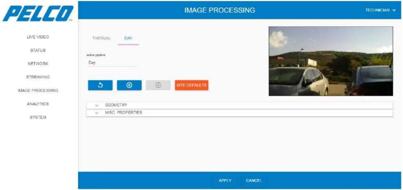
- Applicable for video processing only: click SITE DEFAULTS to revert the entire settings to your local site settings (saved during Section 5.11.1.4: Save As Site). The following opens:
Are you sure you want to revert settings to site defaults?
This will undo all previous settings
CANCEL
OK
-
Click OK to approve.
-
Click APPLY for the changes to take effect (click CANCEL to revert your changes).
5.9.2.1 Geometry Settings
Expand the Geometry Settings option. The following opens (click APPLY for the changes to take effect, click to revert your changes):
Figure 5-40: Image Processing Window - Day Tab - Geometry Settings
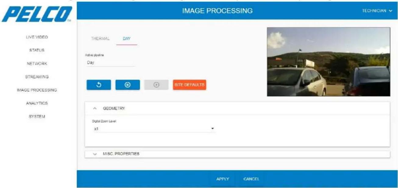
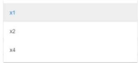
The Geometry Settings option consists of the following parameter:
Digital Zoom Level:
5.9.2.2 Misc. Properties Settings
Expand the Misc Properties Settings option. The following opens (click APPLY for the changes to take effect, click CANCEL to revert your changes):
Figure 5-41: Image Processing Window - Day Tab - Misc Properties Settings
![PELCO TM IMAGE PROCESSING TECHNICIAN LIVE VIDEO STATUS NETWORK STREAMING IMAGE PROCESSING ANALYTICS SYSTEM THERMAL DAY Active pipeline Day SITE DEFAULTS GEOMETRY MISC. PROPERTIES Brightness [-4, 4] 0 Color Effects -0 Contrast [-4, 4] 0 Focus. Absolute [0, 255] 1 Horizontal Flip Flue [-100, 150] 0 Saturation [-4, 4] 0 Vertical Flip White Balance, Automatic APPLY CANCEL](/content/2026/06/1147139/images/dc362c8f358475879d792db9402f3c602a30829954aa53919e30b3f3b868ef08.jpg)
The Misc. Properties Settings option consists of the following detector parameters:
Brightness
Color Effects
Contrast
➢ Focus, Absolute: 0: Automatic, 1: infinity (recommended).
▶ Horizontal Flip
Hue
Saturation
▶ Vertical Flip
➢ White Balance, Automatic: not active.
5.10 Analytics Window
The Analytics Window enables detecting and tracking movement within predefined ROIs, as well as for teaching the system where movement typically occurs.
- Click Analytics. The Analytics window opens (all collapsed):
Figure 5-42: Analytics Window (all collapsed)
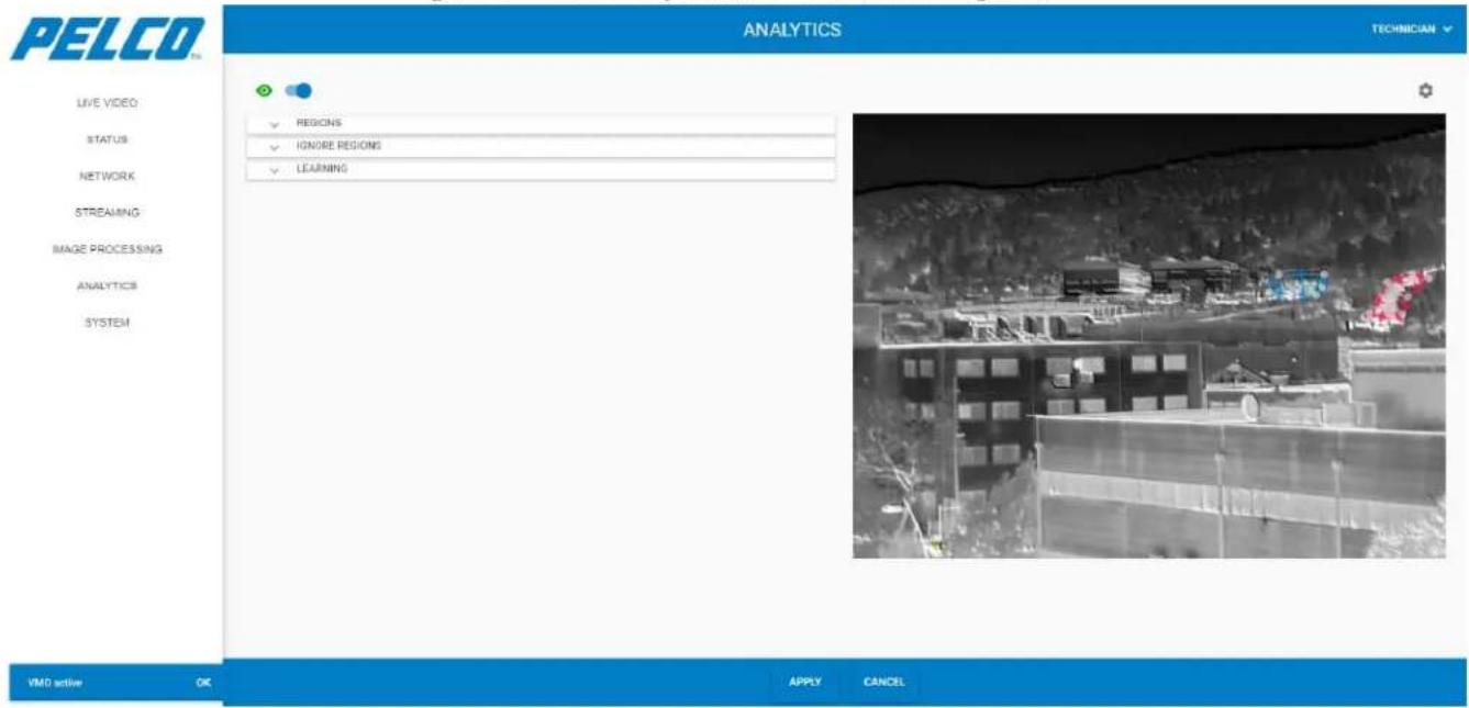
The Analytics window is comprised of three tabs:
Regions Tab: enables marking of regios to detect movement (see Section 5.10.1).
➢ Ignore Regions Tab: enables marking of regions in which movement is ignored (see Section 5.10.2).
➢ Learning Tab: enables the system to learn the viewed scene and where movement typically occurs (see Section 5.10.3).
NOTE
When entering the Analytics window, either of the following messages is displayed on the lower-left corner of the screen, depending on whether VMD is active or disabled. Click OK to close these messages.


NOTE
To enable/disable viewing analytics, click in the top-left corner of the screen to toggle between enable and disable. Click APPLY for the changes to take effect (click CANCEL to revert your changes).
5.10.1 Regions Tab
The Regions tab enables marking regions to detect movement.
- Expand the Regions tab. The following opens:
Figure 5-43: Analytics Window - Regions Tab
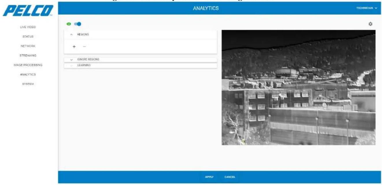
- Click the + sign. The following opens (example):
Figure 5-44: Analytics Window - Regions Tab - Region Options
![PELCO TM ANALYTICS TECHNICIAN LIVE VIDEO STATUS NETWORK STREAMING IMAGE PROCESSING ANALYTICS SYSTEM ● REGIONS + - Region 1 Name Tide Minimum Detection Size Region 2 Area Human ONWIP Alts Maximum Speed [7, 28] Area direction 12 No entry ✓ IGNORE REGIONS ✓ LEARNING APPLY CANCEL](/content/2026/06/1147139/images/c8e2e2340eb668b9fabfce7ab8ea38b62a251f00d374c998fae66f56e0e25b4d.jpg)
- Click in the Name field and enter a region name.
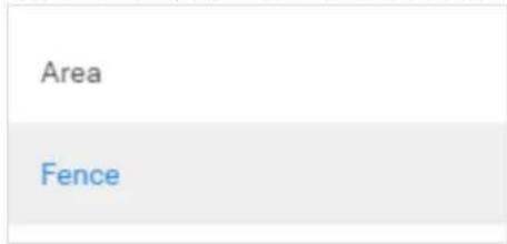
- Select region type from the following options:
Area – detection is done within a close frame.
Fence – detection is done for objects moving towards a predefined line.
NOTE
Some region options change depending on the type of region selected.
5. Select the following parameters:
- Minimum Detection Size: determines the size and characters of the object to be detected.
| Animal |
| Human |
| Vehicle |
• ONVIF Alert: enabling receiving alerts which conform to ONVIF protocol.
• Maximum Speed: fastest speed that will be detected, in m/sec (default: 1 m/sec)
- Area Direction: determines the type of object movement (in relation to the region) that will be detected (this option is available when Area type region is selected)
| No entry |
| No exit |
| Any |
- Fence direction: determines the type of object movement (in relation to the fence line) that will be detected (this option is available when Fence type region is selected)
| Left to right |
| Right to left |
| Any |
-
Click the live image to mark the region frame points.
-
Double click the region starting point to end the region marking.
Figure 5-45: Analytics Window - Regions Tab - Area ROI
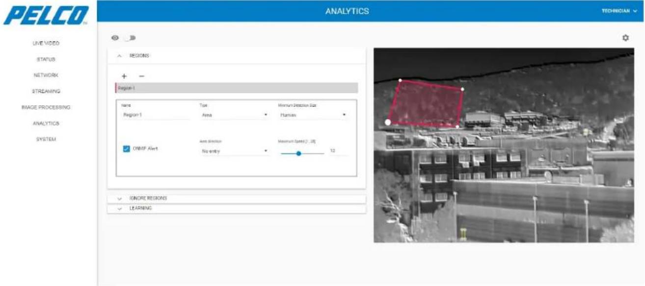
Figure 5-46: Analytics Window - Regions Tab - Fence ROI
![PELCO ANALYTICS TECHNICIAN LIVE VIDEO STATUS NETWORK STREAMING IMAGE PROCESSING ANALYTICS SYSTEM REGIONS + - Region-1 Name Type Human Detection Size Region-1 Fence Human 0M/F Alert Maximum speed [ ] , 36 12 Face direction Left to right IGNORE REGIONS LEARNING APPLY CANCEL](/content/2026/06/1147139/images/c7924251b81e4f6e899a6d3e5c4c0a06b26c89b5b3a1007b7ab0e4d8f639a745.jpg)
NOTE
The color next to the region name corresponds with the color of the region marked on the image.
- To delete a region definition: select the region (Region-1 or Region-2 in the example) and click the - sign.
- Click APPLY for the changes to take effect (click CANCEL to revert your changes).
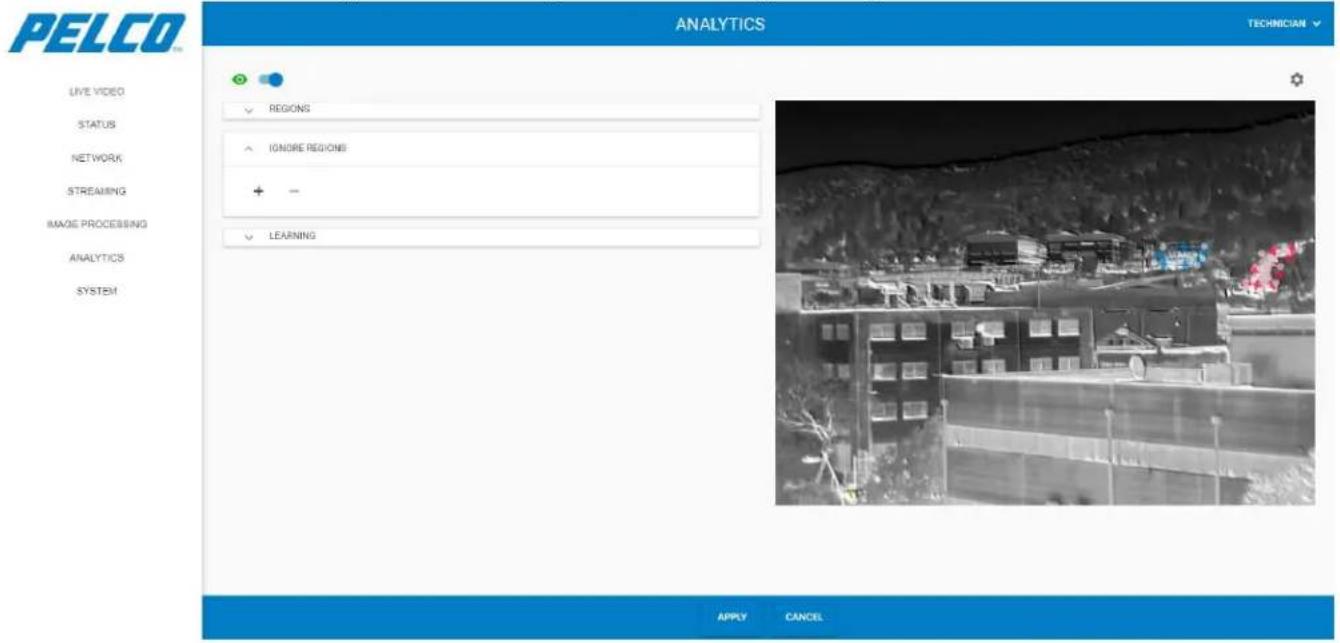
5.10.2 Ignore Regions Tab
The Ignore Regions tab enables marking regions in which movement is ignored. Expand the Ignore Regions tab. The following opens:
Figure 5-47: Analytics Window - Ignore Regions Tab
- Click the + sign. The following opens (example):
Figure 5-48: Analytics Window - Ignore Regions Tab - Ignore Regions ROI (1 of 2)
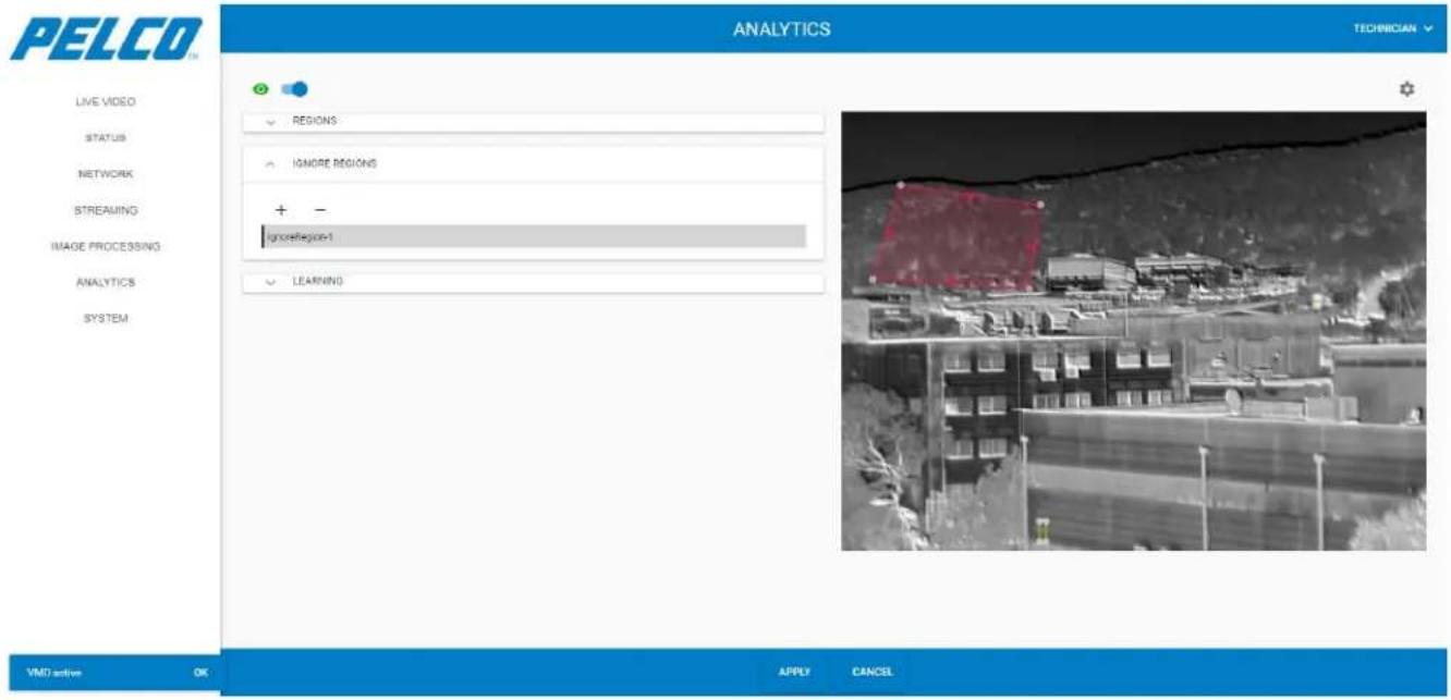
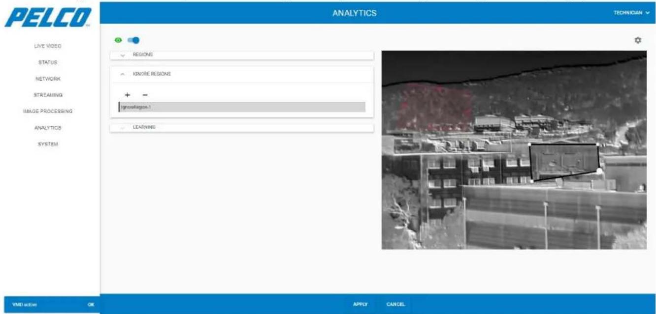
- Click the live image to mark the Ignore Region frame points.
- Double click the region starting point to end the Ignore Region marking.
Figure 5-49: Analytics Window - Ignore Regions Tab - Ignore Regions ROI (2 of 2)
- To delete an Ignore Region definition: select the ignore region (IgnoreRegion-1 or IgnoreRegion-2 in the example) and click the - sign.
- Click APPLY for the changes to take effect (click CANCEL to revert your changes).
5.10.3 Learning Tab
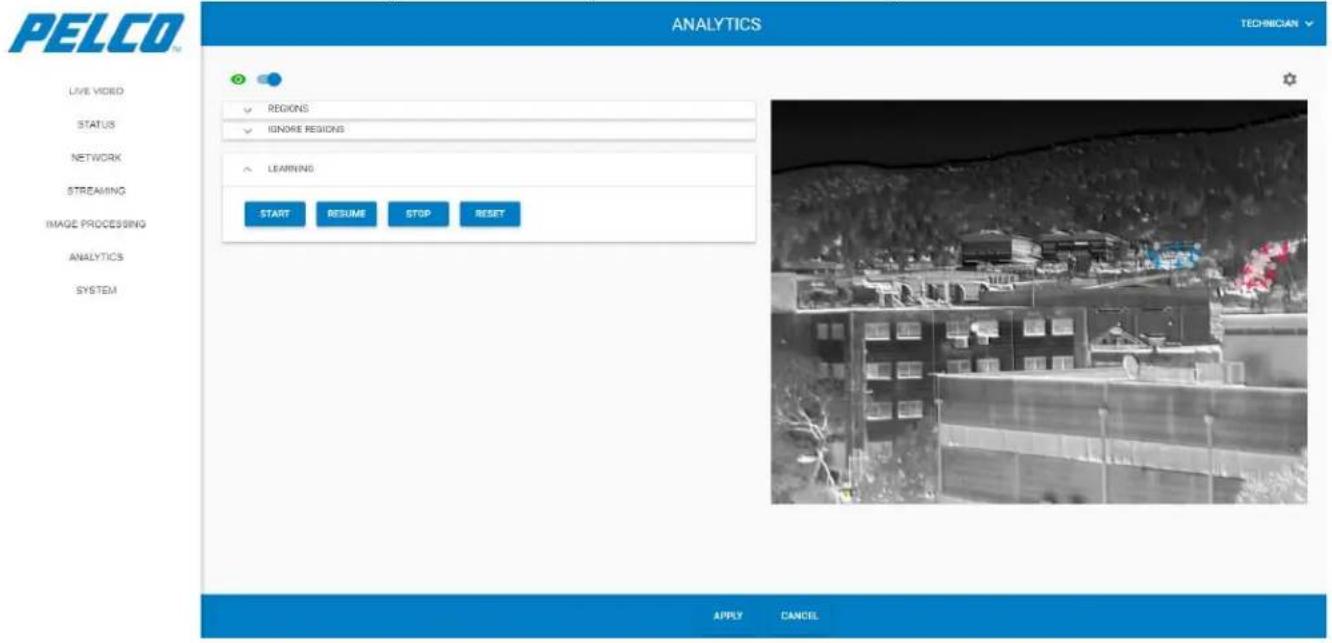
The Learning tab enables the system to learn the scene and where movement typically occurs. Expand the Learning tab. The following opens:
Figure 5-50: Analytics Window - Learning Tab
-
Click either of the following buttons:
-
Click to start the learning session.
- Click to resume the learning session after the Stop button was activated.
- Click ____ to stop the learning session (if, for example, unusual activity is occurring).
- Click to delete the learning session in progress.
START
RESUME
STOP
RESET
NOTE
VMD must be active (i.e., the toggle button in the top-left corner of
the screen must appear like this: ) to start the learning session.
NOTE
When the Start button is pressed, the following message is displayed on the lower-left corner of the screen. Click OK to close this message.
VMD in learning
OK
5.10.4 Analytics Settings
Click in the upper-right corner of the screen. The following opens:
Figure 5-51: Analytics Window - Analytics Settings
![PELCO LIVE VIDEO STATUS NETWORK STREAMING IMAGE PROCESSING ANALYTICS SYSTEM ANALYTICS TECHNICIAN ActiveBloodPresent[0, 10] 70 Booksize 4 Draw Region Draw Target Box Draw Target Trail Intr Noise Level [0, 12] 4 LearningTime [0, 1300] 30 MaxTargetTrailLength [20, 1300] 120 Source History 2 TTL [0.5, 18] 2 Track All Frame Warming Time [0.04, 16] 0.4 VMD active OK APPLY CANCEL](/content/2026/06/1147139/images/2f920a04a3f4f8f5fec16fe022a9371d158c24d089adfbce7abad02a2285ad08.jpg)
The Analytics Settings window consists of the following parameters:
➢ ActiveBlockPercent: Percentage of the block area that should be active in order to detect movement (default: 70%)
BlockSize: minimum block size (default: 8)
➢ Draw Region: enabling drawing of region
➢ Draw Target Box: enabling frame overlay around the moving target
Draw Target Trail: enabling trail showing the path the moving target has taken. The maximum trail length is determined by “MaxTargetTrailLength”
➢ Initial Noise Level: higher level reduces the effect of noise in a scene, but also reduces detection sensitivity (default: 6)
➢ LearningTime: length of time, in seconds, the learning session will run (default: 30 seconds)
MaxTargetTrailLength: trail length, in FPS (default: 120 FPS). Will not display if “Draw Target Trail” is not enabled
➢ Scene History: minimum number of frames that are used for movement detection (default: 2)
TTL: length of time, in seconds, a target will continue to be considered a target after it hasn't been seen (default: 2 seconds)
Track All Frame: enabling tracking of target in entire image frame, not just in the ROI the object was detected in
➢ Warning Time: elapsed time, in seconds, until the system defines the identified object as a target (default: 0.4 seconds)
NOTE
To close the Analytics Settings screen, click ✗ in the upper-right corner of the screen. Any changes that were made are retained.
5.11 System Window
The System Window consists of five tabs:
Admin Tab (see Section 5.11.1)
➢ Logs Tab (see Section 5.11.2)
Date and Time Tab (see Section 5.11.3)
➢ File Upload Tab (see Section 5.11.4)
User Management Tab (see Section 5.11.5)
5.11.1 Admin Tab
Click ADMIN. The following opens:
Figure 5-52: System Window - Admin Tab
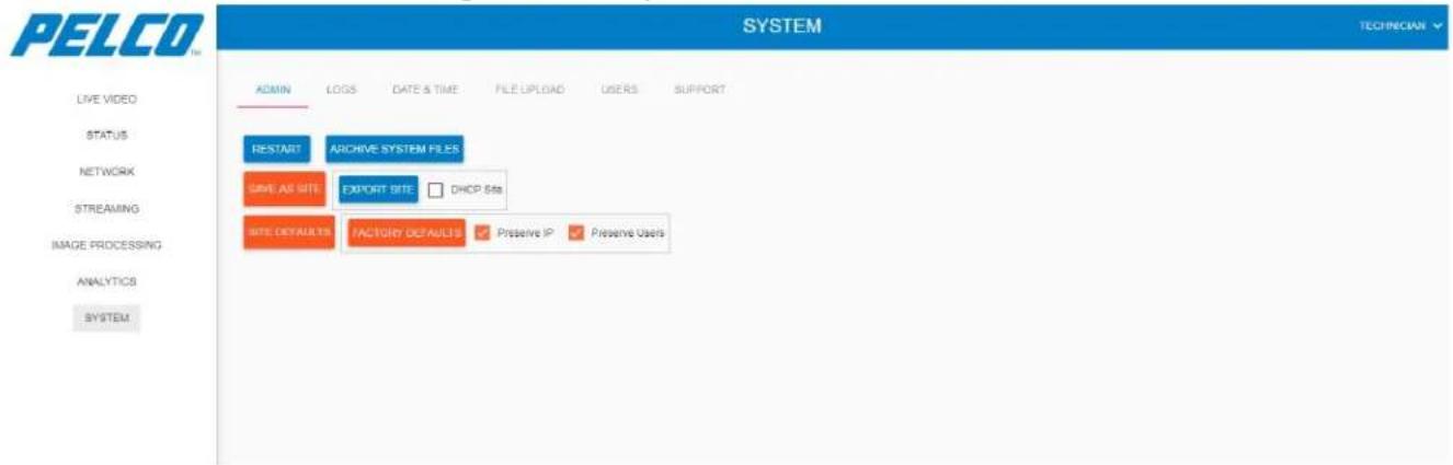
5.11.1.1 Restart
To completely restart the entire system:
- Click . The following opens:
Figure 5-53: System Window - Admin Tab - Restart Aproval
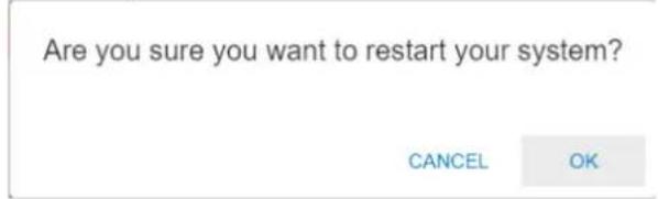
- Click OK to approve the system restart. The following opens, stating that the restart process could take a few minutes:
Figure 5-54: System Window - Admin Tab - Restart
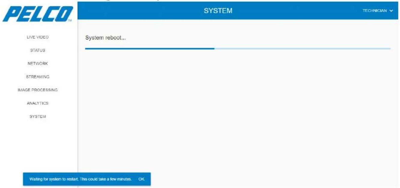
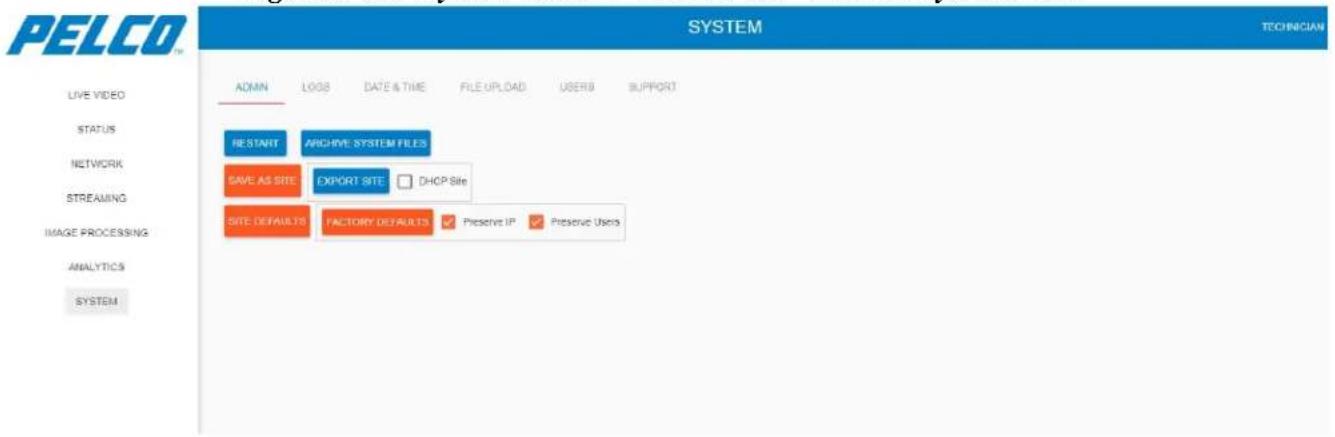
On completion, the following opens prompting that the restart is completed:
Restart Completed. Page will refresh shortly. OK
5.11.1.2 Archive System Files
To archive the entire system files:
- Click ARCHIVE SYSTEM FILES . The following opens, prompting that the archiving is in process:
Figure 5-55: System Window - Admin Tab - Archive System Files
On completion, the following opens prompting to approve the download of the archived file:
Archiving done. Do you want to download archive?
NO
YES
- Click Yes to download the file. The file is downloaded and saved in your \Downloads folder. File name: System-files.tgzx.
5.11.1.3 Save As Site
To save the current settings of the camera and the GUI as site defaults:
- Click . The following opens:
Figure 5-56: System Window - Admin Tab - Save As Site Approval
Are you sure you want to save current settings as site defaults?
CANCEL
OK
- Click OK to proceed. The following opens, prompting that site defaults save is in process:
Figure 5-57: System Window - Admin Tab - Save As Site
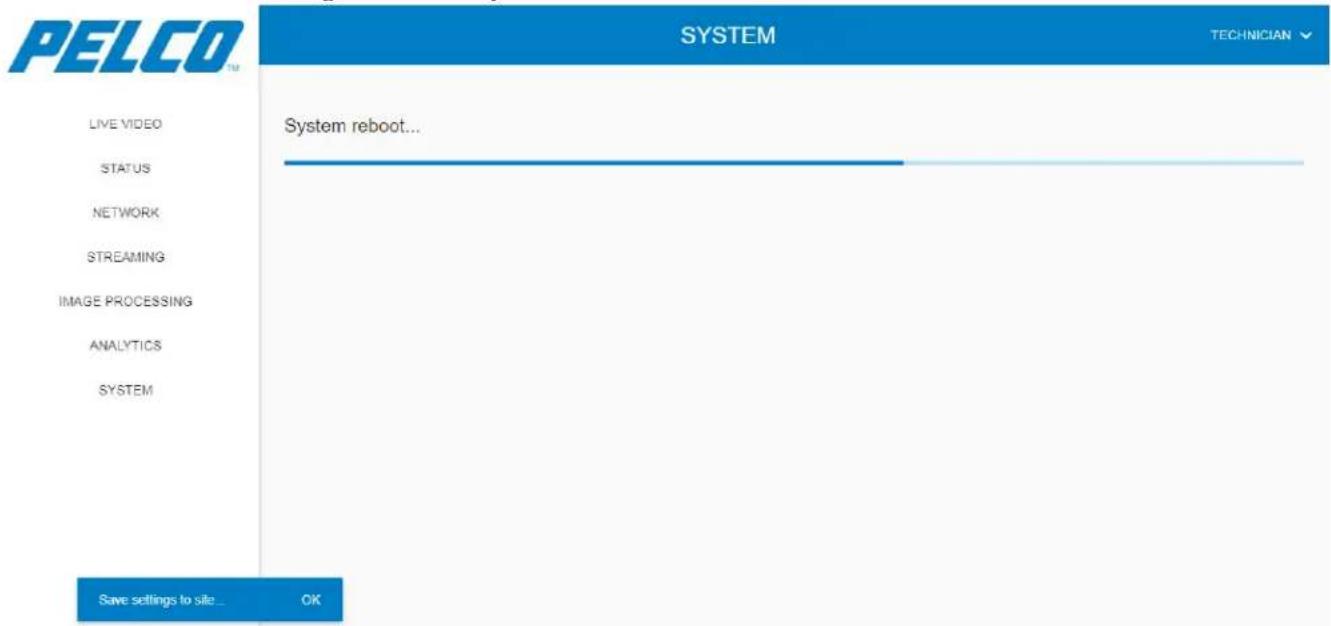
On completion, the following opens prompting that the site defaults are saved:
Settings saved to site
OK
To download an archived file that contain the site defaults:
- Click EXPORT SITE. The following opens prompting to approve the site defaults download:
Figure 5-58: System Window - Admin Tab - Export Site Approval
Do you want to configure site with DHCP?
NO
YES
- Click Yes to download the file with DHCP, OR:
Click No to download the file with a constant IP address.
The file is downloaded and saved in your \Downloads folder. File name: site-defaults.tgzx.
To revert system settings back to the site defaults settings:
- Click Site Defaults. The following opens prompting to approve the revert process:
Figure 5-59: System Window - Admin Tab - Site Defaults Approval
Are you sure you want to revert settings to site defaults?
This will undo all previous settings while keeping site settings
CANCEL
OK
- Click OK. The following opens, prompting that the site defaults restoration is in process:
Figure 5-60: System Window - Admin Tab - Site Defaults
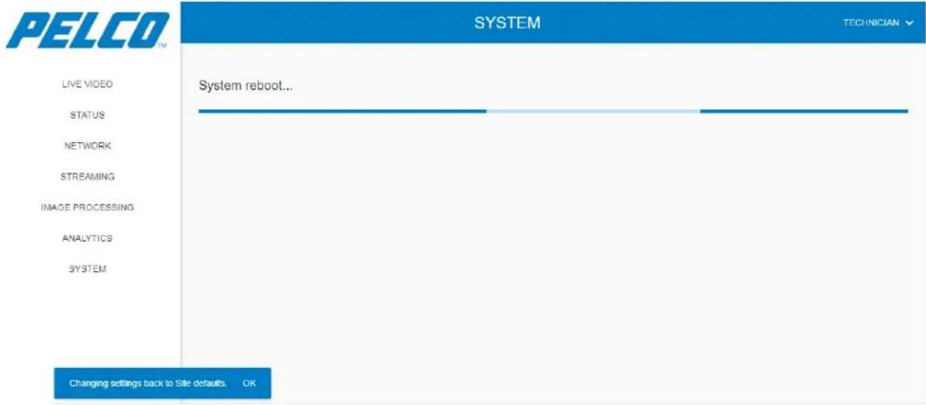
On completion, the following opens prompting that the site defaults are saved:
Settings are back to Site defaults. OK
5.11.1.6 Factory Defaults
To revert settings to factory defaults:
- Click FACTORY DEFAULTS. The following opens prompting to approve the revert process:
Figure 5-61: System Window - Admin Tab - Factory Defaults Approval
Are you sure you want to revert settings to factory defaults?
This will undo all previous settings, including site settings
CANCEL
OK
NOTE
If Preserve IP is unchecked, the system will restart with the default IP.
If Preserve Users is unchecked, all users will be deleted upon system restart.

- Click OK. The following opens, prompting that the factory defaults restoration is in process:
Figure 5-62: System Window - Admin Tab - Factory Defaults
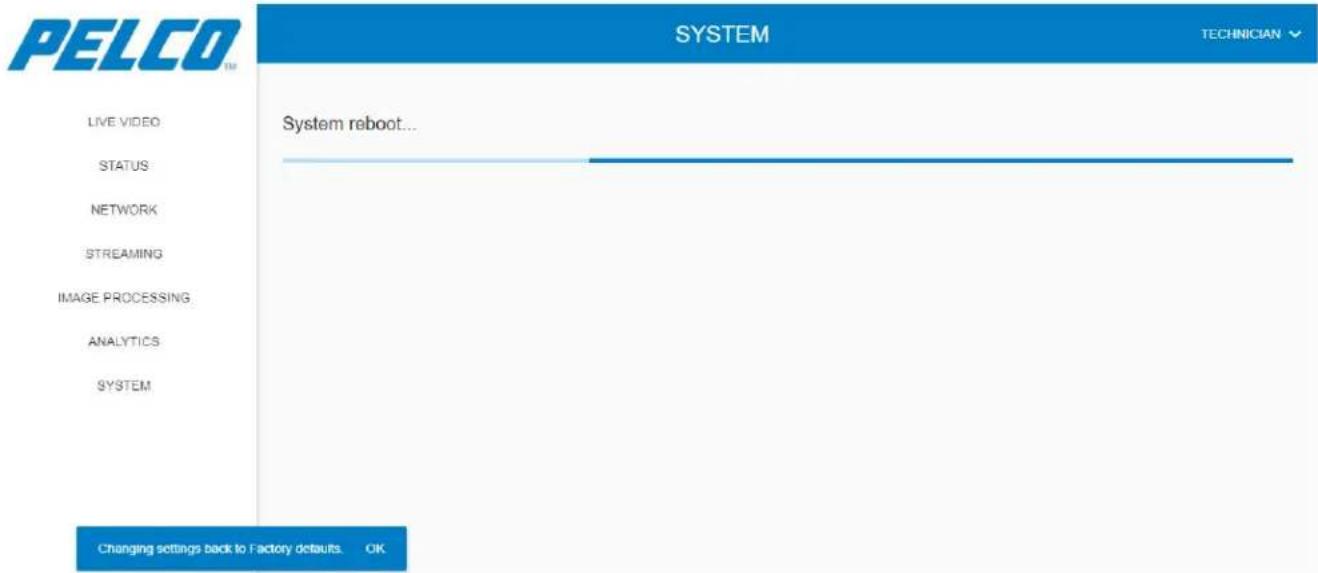
On completion, the following opens prompting that the factory defaults are saved:
Settings are back to Factory defaults.
OK
5.11.2 Logs Tab
The Status tab allows downloading data files from the Sarix TI Camera. This is mainly useful when troubleshooting possible Sarix TI Camera malfunctions by Pelco's technical support team.
- Click System and select Log Files. The Status tab displays a list of logs (example):
Figure 5-63: System Window - Logs Tab
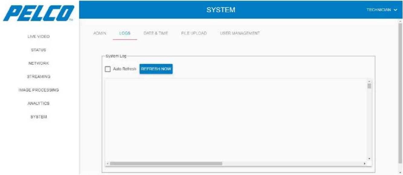
- To refresh the list click

5.11.3 Date and Time Tab
CAUTION
Time synchronization is extremely important for the ONVIF handshake. If the time is not correctly synchronized, the camera may not connect over ONVIF.
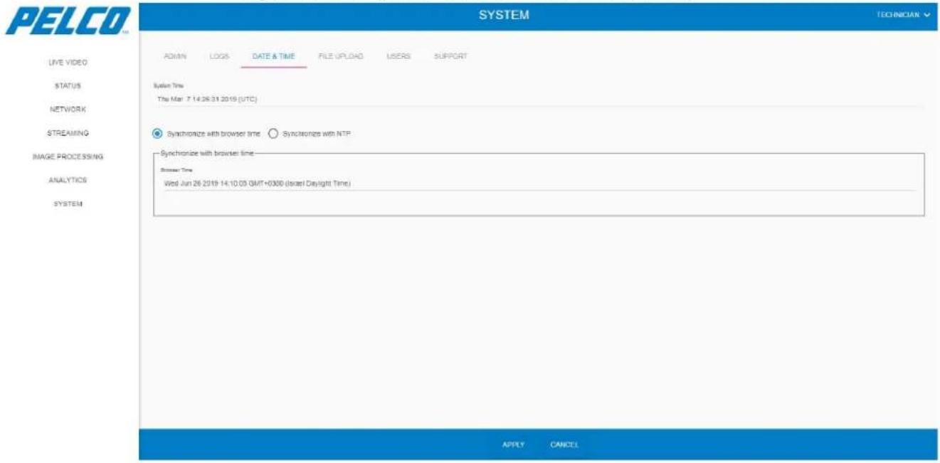
The Date and Time tab allows synchronizing of the Sarix TI Camera time and date according to several methods:
Click System and select the DATE & TIME tab. The Date & Time tab opens:
Figure 5-64: System Window - Date and Time Tab
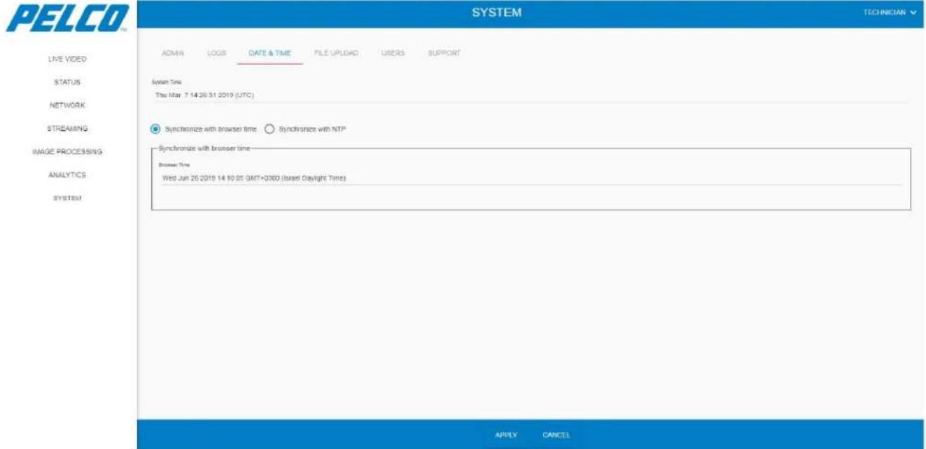
5.11.3.1 Synchronizing with Browser Time
Select the Synchronize with browser time option. The following opens:
Figure 5-65: System Window - Date and Time Tab - Synchronizing with Browser Time
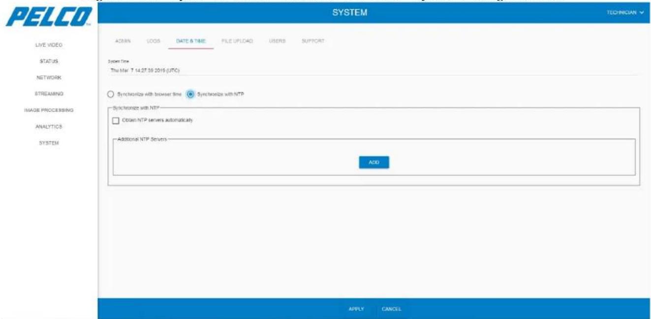
5.11.3.2 Synchronizing with NTP
Select the Synchronize with NTP option. The following opens:
Figure 5-66: System Window - Date and Time Tab - Synchronizing with NTP
5.11.4 File Upload Tab
The File Upload tab allows updating your Sarix TI Camera with FM/SW.
- Click System and select the FILE UPLOAD tab. The File Upload tab opens:
Figure 5-67: System Window - File Upload Tab
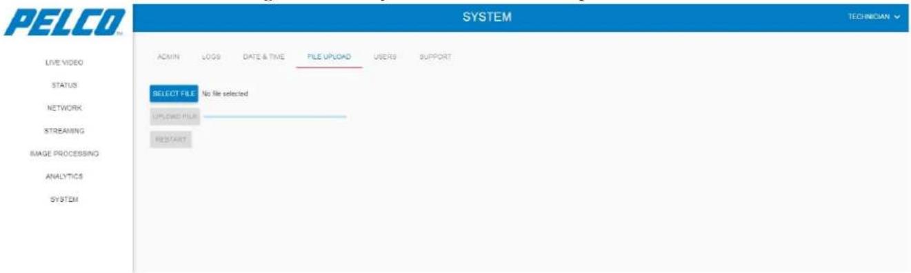
- Click SELECT FILE to browse and select the required FM/SW file (*.tgzx file format).
- Click UPLOAD FILE. The uploading process is started. On completion, the RESTART button is valid.
- Click RESTART to validate the Sarix TI Camera with the FM/SW uploading process.
5.11.5 User Management Tab
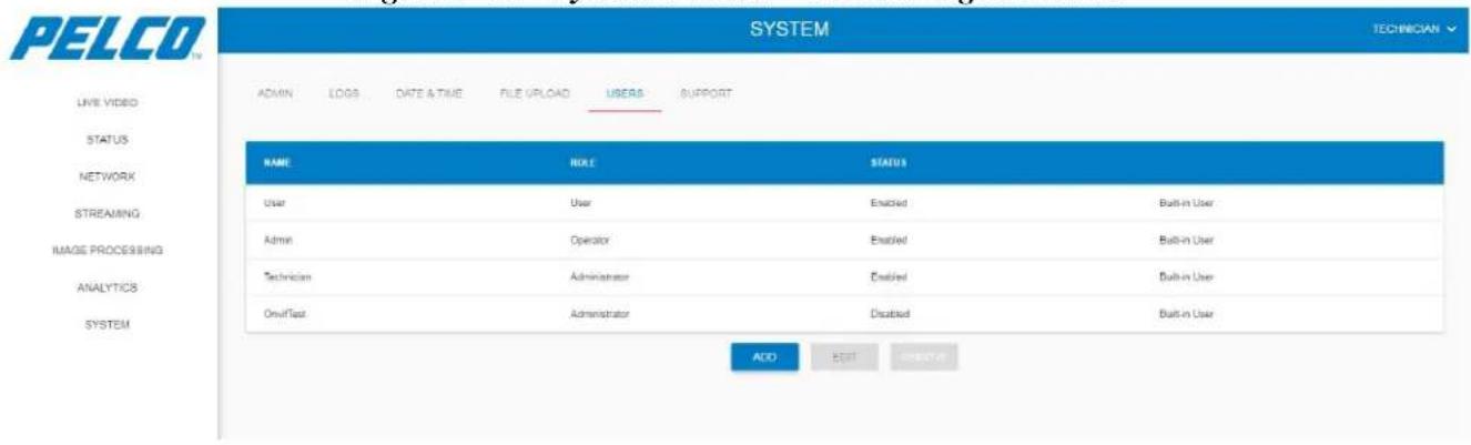
The User Management tab is used to manage user's login permissions.
Click System and select the User Management tab. The User Management tab opens:
Figure 5-68: System Window - User Management Tab
5.11.5.1 Adding a User
To add a new user:
- Click . The following opens:
Figure 5-69: System Window - User Management Tab - Adding a User
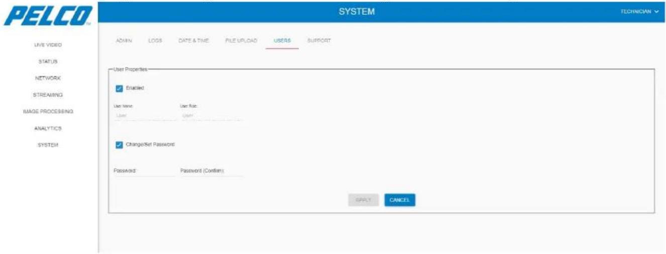
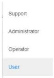
- Enter the User Name.
- From the User Role drop-down list select the usage-level of the user:
- Click APPLY to validate the changes.
5.11.5.2 Editing User Details
- Select a user and click EDIT
Figure 5-70: System Window - User Management Tab - Editing User Details
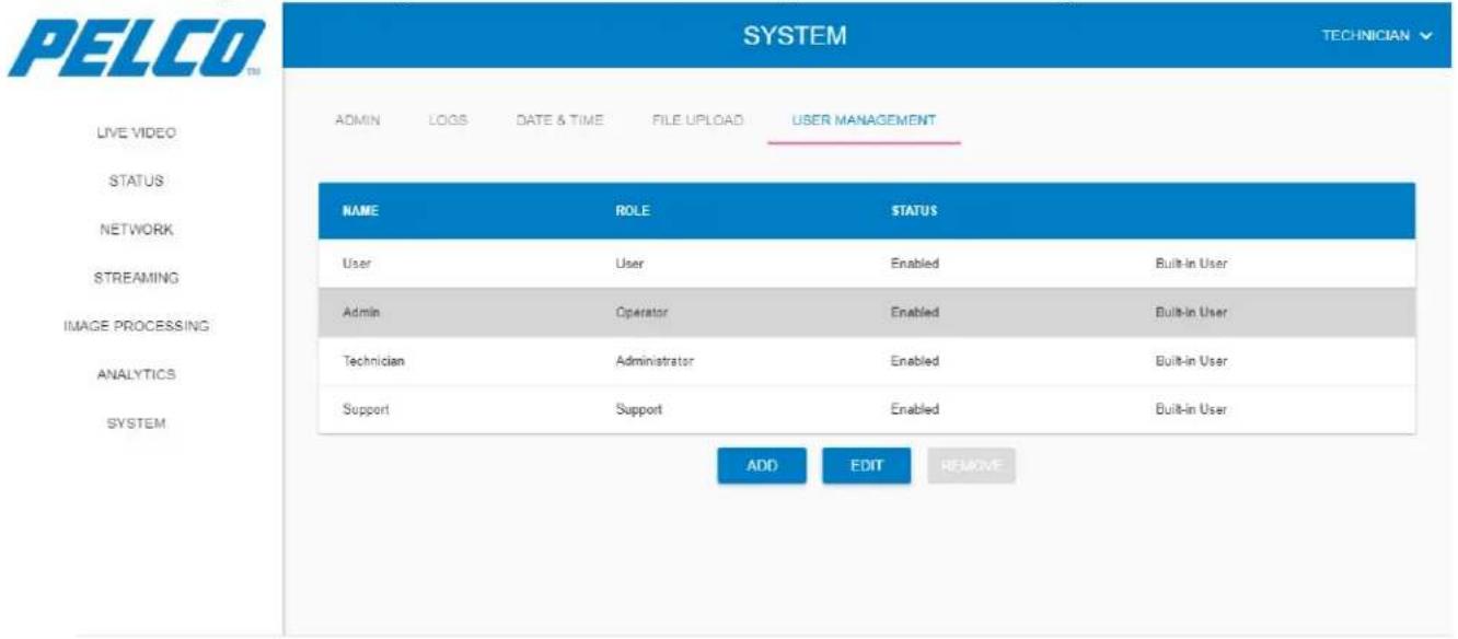
- Change the user details.
- Click APPLY to validate the changes.
5.12 Logging Out from the Web GUI
- Stop any action, currently in process.
- From the upper-right drop-down menu select Logout:
Figure 5-71: Logging Out from the Web GUI - Drop Down Menu
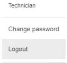
The user is logged out from the program and the Status window re-opens (see Figure 5-2).
6. Maintenance
This chapter provides the Sarix TI Series Camera preventive maintenance instructions.
The chapter consists of the following sections:
Section 6.1: Visual Inspection
Section 6.2: Cleaning
6.1 Visual Inspection
- Visually inspect the camera and check the physical condition of the camera's chassis and lens.
- Check the physical condition of the cable (torn, over-bending, damaged isolation, bent or immersed pins).
6.2 Cleaning
CAUTION
Do not use any chemicals for cleaning the Sarix TI Camera. Failure to comply could result in damage to the Sarix TI Camera optical-lens and/or its surfaces.
- Clean the Sarix TI Camera using wipes approved for optical equipment.
- Clean any stains using a cotton-cloth, slightly dumped in tap water.
7. Ordering Information
This chapter provides information for purchasing the Sarix TI Series Camera and accessories. The chapter consists of the following sections:
7.1 Ordering Information
Table 7-1: Ordering Information for 03 Hz Camera
| Lens Type | Part Number | |
| 17μ 640x480 | 14.2mm f/1.2, Athermalized, Fixed Focus | TI2614 |
| 35mm f/1.2, Athermalized, Fixed Focus | TI2635 | |
| 50mm f/1.2, Athermalized, Fixed Focus | TI2650 | |
| 17μ 384x288 | 14.2mm f/1.2,Athermalized, Fixed Focus | TI2314 |
| 35mm f/1.2,Athermalized, Fixed Focus | TI2335 | |
| 50mm f/1.2,Athermalized, Fixed Focus | TI2350 |
Table 7-2: Ordering Information for 9Hz Camera
| Lens Type | Part Number | |
| 17μ 640x480 | 14.2mm f/1.2, Athermalized, Fixed Focus | TI2614-1 |
| 35mm f/1.2, Athermalized, Fixed Focus | TI2635-1 | |
| 50mm f/1.2, Athermalized, Fixed Focus | TI2650-1 | |
| 17μ 384x288 | 14.2mm f/1.2,Athermalized, Fixed Focus | TI2314-1 |
| 35mm f/1.2,Athermalized, Fixed Focus | TI2335-1 | |
| 50mm f/1.2,Athermalized, Fixed Focus | TI2350-1 |
7.2 Ordering Accessories
Table 7-3: Ordering Accessories
| Part Number | |
| Accessories: | |
| SARIX TI POW cable 50 FT | TICAB-P50 |
| Wall Mount Accessories: | |
| SARIX TI Wall Mount | TIWM |
| SARIX TI Pole Adapter REQ Wall MNT | TIPA |
8. Index
This chapter provides a list, arranged in alphabetical order, of keywords found throughout this manual.
A
Abbreviations · 1-11
Streaming Window · 5-21
System Window · 5-51
GUI·2-17
C
Certificates
Request · 5-19
Self-Signed Request · 5-19
Uploading a Certificate · 5-20
Cleaning · 6-63
D
Day Tab · 5-12, 5-25
Main Stream · 5-25
Secondary Stream · 5-27
Changing Password · 5-5
Image Processing Window · 5-29
Live View Window · 5-7
Logging Into GUI · 5-3
Logging Out · 5-62
Main Window · 5-6
Network Window · 5-15
Status Window · 5-8
I
Image Processing Window · 5-29
Day Tab · 5-37
Day Tab Geometry Settings · 5-38
Day Tab Misc Properties Settings · 5-39
Thermal Tab · 5-29
Thermal Tab Advanced Settings · 5-33
Thermal Tab Basic Settings · 5-30
Thermal Tab Color Processing Settings · 5-34
Thermal Tab Gain Control Settings · 5-32
Thermal Tab Signal Processing Settings · 5-31
Installation · 4-1
Camera Installation · 4-2
Unpacking · 4-1
Installing Camera · 4-2
IP PoE Cable · 4-6
Mechanical Interface Preparation · 4-2, 4-3
Pole Mount Configuration · 4-5
Wall Mount Configuration · 4-4
L
Live View Window · 5-7
LOF·1-7
Logging Out · 5-62
Login · 5-3
LOT·1-7
M
Main Window Overview · 5-6
Maintenance · 6-63
Cleaning · 6-63
Visual Inspection · 6-63
N
Network Window · 5-15
Certificates · 5-19
HTTPS Connection · 5-17
IP Address · 5-16
IP Address - Auto · 5-16
Manual DNS Server Address · 5-17
ONVIF Service · 5-18
Resetting Network Settings · 5-18
o
Operation · 5-1
Ordering Info · 7-64
Overview·2-13, 2-14
Features · 2-14
GUI·2-17
Physical Description · 2-15
Specifications · 2-18
P
Password Change · 5-5
Physical Description · 2-15
R
Revisions · 1-1
S
Safety · 3-1
Safety Conventions · 3-1
Safety During Installation · 3-2
Safety During Maintenance · 3-2
Safety Instructions
Conventions · 3-1
Installation · 3-2
Maintenance·3-2
Scope · 1-12
Specifications · 2-18
CMOS Camera · 2-20
Configurations · 2-19
System Specifications · 2-18
Thermal Camera · 2-20
Status Window · 5-8
Status Window Overview
Day Tab · 5-12
Date & Time Tab - Sync with Browser · 5-59
Date & Time Tab - Sync with NTP · 5-59
File Upload Tab · 5-60
Logs Tab · 5-57
User Management Tab · 5-60
User Management Tab - Adding a User · 5-61
User Management Tab - Editing a User · 5-62
T
Thermal Tab · 5-10, 5-21
Main Stream · 5-22
Secondary Stream · 5-24
TOC · 1-2
V
Visual Inspection · 6-63
U
Unpacking · 4-1
PELCO®
Pelco, Inc. 625 W. Alluvial Ave. Fresno, CA 93711 Tel. +1 559-292-1981 www.pelco.com
Pelco, the Pelco logo, and other trademarks associated with Pelco products referred to in this publication are trademarks of Pelco, Inc. or its affiliates. ONVIF and the ONVIF logo are trademarks of ONVIF Inc. All other product names and services are the property of their respective companies.
Product specifications and availability are subject to change without notice.
© Copyright 2019, Pelco, Inc. All rights reserved.
- Sarix TI Series Camera
- User Manual
- Pelco Troubleshooting Contact Information
- Table of Contents
- Important Notices .... 1-8
- Overview 2-13
- Safety 3-1
- Installation....4-1
- Operation 5-1
- List of Figures
- List of Tables
- Important Notices
- Regulatory Notices [FCC Class A]
- Radio and Television Interference
- Legal Notice [Audio Notice]
- Video Quality Caution
- Frame Rate Notice Regarding User Selected Options
- Open Source Software
- CCC Power Cord Statement
- NOTE
- 2.4 GHZ Radio Device
- Warranty
- Network Topology Statement
- Scope of This Manual
- Overview
- Overview
- Features
- Physical Description of the Camera
- Marking
- Sarix TI Web GUI
- Technical Data and Specifications
- System Specifications
- Configurations
- Thermal Camera
- CMOS Camera
- Safety
- Safety Conventions
- WARNING
- CAUTION
- Safety During Installation
- Safety During Maintenance
- Installation
- Unpacking
- Camera Installation
- Installation Guidelines and Preparation
- Mechanical Interface Preparation
- Wall Mount Configuration
- Pole Mount Configuration
- Electrical ICD IP PoE Cable
- Operation
- First Time Credentials Setup
- Logging Into Sarix TI Camera Web GUI
- Enter your Username and Password:
- Changing Your Password
- Main Window Overview
- Legend:
- Live View Window
- Status Window
- System Tab
- Thermal Tab
- Day Tab
- Disabling / Enabling a Camera
- Disabling the Camera
- Enabling the Camera
- Network Window
- Setting of IP Address
- Setting an Auto IP Address (DHCP)
- Setting a Manual DNS Server Address
- Settings of HTTPS Connection
- Setting the Network Interface
- Resetting Network Settings
- Restarting ONVIF Service
- Certificates
- Creating a Certificate Request
- Generating a Self-Signed Certificate
- Uploading a Certificate
- Streaming Window
- Thermal Tab
- Main Stream
- Secondary Stream
- Day Tab
- Main Stream
- Secondary Stream
- General Configuration Tab
- Image Processing Window
- Thermal Tab
- You can:
- Basic Settings
- Signal Processing Settings
- Gain Control Settings
- Advanced Settings
- Color Processing Settings
- Day Tab
- Geometry Settings
- Misc. Properties Settings
- Analytics Window
- Regions Tab
- Select the following parameters:
- Ignore Regions Tab
- Learning Tab
- START
- RESUME
- STOP
- RESET
- Analytics Settings
- System Window
- Admin Tab
- Restart
- Archive System Files
- Save As Site
- Factory Defaults
- Logs Tab
- Date and Time Tab
- Synchronizing with Browser Time
- Synchronizing with NTP
- File Upload Tab
- User Management Tab
- Adding a User
- Editing User Details
- Logging Out from the Web GUI
- Maintenance
- Visual Inspection
- Cleaning
- Ordering Information
- Ordering Information
- Ordering Accessories
- Index
- A
- C
- D
- I
- L
- LOF·1-7
- M
- N
- o
- P
- R
- S
- T
- PELCO®
Brand : Pelco
Model : Sarix TI2650-1
Category : Security Camera