Sarix Enhanced IME222-1RS - Security Camera Pelco - Free user manual and instructions
Find the device manual for free Sarix Enhanced IME222-1RS Pelco in PDF.


| Product Type | Security Camera |
| Brand | Pelco |
| Model | Sarix Enhanced IME222-1RS |
| Series | NextGen Sarix Enhanced IME Series |
| Resolution | 2 MP (1920x1080) |
| Image Sensor | 1/2.8" Progressive Scan CMOS |
| Lens Type | Varifocal, 3-9 mm |
| Field of View | Horizontal: 36° to 96° (approximate) |
| Day/Night | Yes, with IR-cut filter |
| IR Distance | Up to 30 m (depending on scene) |
| Wide Dynamic Range | Yes, SureVision with WDR and anti-bloom |
| Minimum Illumination | Color: 0.05 lux; B/W: 0.01 lux; 0 lux with IR |
| Video Compression | H.265, H.264, MJPEG |
| Network Interface | 10/100/1000Base-T Ethernet, RJ-45 |
| Protocols | IPv4, IPv6, TCP, UDP, HTTP, HTTPS, ONVIF Profile S/G |
| Power Supply | PoE (IEEE 802.3af/at) or 12 VDC / 24 VAC |
| Power Consumption | Max 12 W (PoE) |
| Mounting | Surface mount (included), optional in-ceiling, pendant, wall |
| Environmental Rating | IP66, Type 4X (with optional plate) |
| Operating Temperature | -10°C to 50°C (14°F to 122°F) |
| Dimensions (Lens Base) | 4.9" (125 mm) diameter, 3.9" (100 mm) height (approx.) |
| Weight | 1.0 kg (2.2 lbs) (approx.) |
| Storage | MicroSD slot (up to 128 GB) |
| Alarm I/O | 1 alarm input, 1 alarm output |
| Audio | 2-way audio (line in/out) |
Frequently Asked Questions - Sarix Enhanced IME222-1RS Pelco
User questions about Sarix Enhanced IME222-1RS Pelco
0 question about this device. Answer the ones you know or ask your own.
Ask a new question about this device
Download the instructions for your Security Camera in PDF format for free! Find your manual Sarix Enhanced IME222-1RS - Pelco and take your electronic device back in hand. On this page are published all the documents necessary for the use of your device. Sarix Enhanced IME222-1RS by Pelco.
USER MANUAL Sarix Enhanced IME222-1RS Pelco
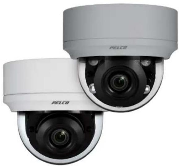
Next Gen Sarix® Enhanced IME Series Mini Dome Cameras
natural_image
Two PELCO security cameras with visible lens and camera modules (no text or symbols on the devices themselves)Installation Manual C1338M 7/17
Contents
Important Notices.... 3
Legal Notice....3
Regulatory Notices .... 3
Korean Class A EMC 3
Warranty Statement.... 3
Introduction 4
Models 5
Recommended Mounts....5
Optional Accessories 5
Getting Started....6
Surface Mount Models....7
Supplied Parts List....7
User-Supplied Parts List....7
Product Overview 8
Installation....9
Installing the Mount....9
In-Ceiling: Indoor and Environmental 9
Pendant: Indoor and Environmental 12
Surface Mount: Indoor and Environmental 15
Wall Mount: Indoor.... 17
Cable Terminations....22
Ethernet Wiring Requirement for PoE 22
Alarm/Relay/Audio Port 23
IP Address Settings 24
Logging On to the Camera 24
Important Notices
For more information about Pelco's product-specific important notices and thereto related information, refer to www.pelco.com/legal.
Regulatory Notices
This device complies with Part 15 of the FCC Rules. Operation is subject to the following two conditions: (1) this device may not cause harmful interference, and (2) this device must accept any interference received, including interference that may cause undesired operation.
Radio and Television Interference
This equipment has been tested and found to comply with the limits of a Class A digital device, pursuant to Part 15 of the FCC rules. These limits are designed to provide reasonable protection against harmful interference when the equipment is operated in a commercial environment. This equipment generates, uses, and can radiate radio frequency energy and, if not installed and used in accordance with the instruction manual, may cause harmful interference to radio communications. Operation of this equipment in a residential area is likely to cause harmful interference in which case the user will be required to correct the interference at his own expense.
Changes and modifications not expressly approved by the manufacturer or registrant of this equipment can void your authority to operate this equipment under Federal Communications Commission's rules.
CAN ICES-3(A)/NMB-3(A).
Korean Class A EMC
For information about Pelco's product warranty and thereto related information, refer to www.pelco.com/warranty.
UL Safety Notices
This product is intended to be supplied by a Listed Power Unit marked "L.P.S." (or "Limited Power Source") and rate output 24Vac, 50/60Hz, 1.28 minimum or 48 Vdc, 0.35A minimum.
The product shall be installed by a qualified service person and the installation shall conform to local codes.
Introduction
The NextGen Sarix® IME Series IP cameras feature SureVision technology that seamlessly delivers advanced low-light performance with wide dynamic range (WDR) and anti-bloom technologies that operate simultaneously. They are part of Pelco's Enhanced (E) range of cameras, providing industry-leading image quality and performance.
The IME Series mini dome camera is easy to install, offers flexible mounting options, and uses a standard Web browser for easy remote setup and administration.
The IME Series easily connects to Pelco IP and hybrid systems such as VideoXpert™, Endura® version 2.0 (or later), and Digital Sentry® version 7.3 (or later). The camera is also conformant with ONVIF Profile S and Profile G for connection with third-party software. Pelco offers an application programming interface (API) and software developer's kit (SDK) for interfacing with Pelco's IP cameras.
This document describes the installation and initial setup procedures to begin operating the camera. For more information about operating your camera, refer to the operation manual specific to the product.
NOTE: For additional information about product documentation in English and other languages, go to www.pelco.com/sarix and navigate to the IME Series Web page
Models
IME129-1IS Indoor, 3 \~ 9 mm focal range, surface mount, 1MPx, white
IME229-1IS Indoor, 3 \~ 9 mm focal range, surface mount, 2MPx, white
IME329-1IS Indoor, 3 \~ 9 mm focal range, surface mount, 3MPx, white
IME129-1ES Environmental, 3 \~ 9 mm focal range, surface mount, 1MPx, light gray
IME229-1ES Environmental, 3 \~ 9 mm focal range, surface mount, 2MPx, light gray
IME329-1ES Environmental, 3 \~ 9 mm focal range, surface mount, 3MPx, light gray
IME129-1RS Environmental, 3 \~ 9 mm focal range, surface mount, 1MPx, light gray, IR LED
IME229-1RS Environmental, 3 \~ 9 mm focal range, surface mount, 2MPx, light gray, IR LED
IME329-1RS Environmental, 3 \~ 9 mm focal range, surface mount, 3MPx, light gray, IR LED
Recommended Mounts
WMVE-SR Pendant mount arm, 1.5in., NPT, environmental, light gray
WMVE-SW Pendant mount arm, 1.5in., NPT, indoor, white
IMEICM-E Environmental in-ceiling mount, light gray
IMEICM-I Indoor in-ceiling mount, white
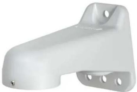
IMEPMB-I Wall mount bracket, light duty, indoor, white
Optional Accessories
PA101 Pole adapter for use with WMVE-SR wall mount
IMEPM-E 1.5-inch NPT environmental pendant adapter, light gray
IMEPM-I 1.5-inch NPT indoor pendant adapter, white
IMEEBAP-E Environmental 4S electrical box and Type 4X adapter
IMEEBAP-I Indoor 4S electrical box adapter
- Contact Pelco Product Support for more information about the use of the Pelco IP camera tester with cameras
Getting Started
Before installing your device, thoroughly familiarize yourself with the information in the installation section of this manual.
NOTES:
- Pelco recommends connecting the device to a network that uses a Dynamic Host Configuration Protocol (DHCP) server to address devices.
- Do not use a network hub when configuring the network settings for the device.
• To ensure secure access, place the device behind a firewall when it is connected to a network.
To ensure secure access, place the device behind a firewall when it is connected to a network.
Surface Mount Models
Supplied Parts List
Qty Description
1 Camera
1 IME Series Mini Dome IP Camera Installation manual
1 Important Safety Instructions
1 Resource sheet
1 RoHS 10 (China only)
1 Power adapter plug (optional)
2 Plastic expansion anchors
3 M4 x 25 mm self-tapping screws
1 Torx T20 security bit
1 Mounting plate (Type 4x)
4 8-32x.5 C-sink (check fit to plate)
2 6-32x.5 C-sink (check fit to plate)
2 M4x.7 x 6 mm screws (Europe)
(Outdoor Cameras Only)
User-Supplied Parts List
Qty Description
1 Conduit (if applicable)
1 Conduit adapters (if applicable)
1 RJ-45 connector to terminate wires
1 Cat5 (or higher) cable
1 #2 Philips screwdriver
1 Tool for drilling
2 Driver 14 " hex for security bit
1 Audio cable (optional)
1 Alarm cable (optional)
1 SD card, up to a 128 GB SanDisk Extreme® PLUS SDHC™ UHS-I MicroSD card, or with adapter to standard SD card size.
Product Overview
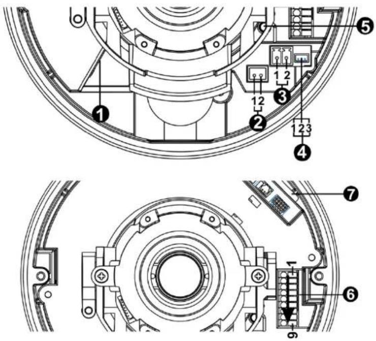
(1) RJ-45 Network Port: Connects the camera to the IP network. Also supplies power to the camera (PoE), through the same connector.
I. To purchase power adaptor, please contact Pelco for further information.
(2) BNC Connector: Not in use.
(3) Power Connector: A two-pin connector for 12VDC and 24VAC. To wire the power connector, remove the green power male adaptor that comes already inserted into the camera. Attach the wires per the diagram above (e.g. Pin 1 is 12VDC or 24VAC 1; Pin 2 is GND or 24VAC 2.) with a small slotted screwdriver and then plug the adaptor plug back into the camera. Do not connect 12VDC or 24VAC power if you are using PoE (Power over Ethernet). Dual power connection can overheat the camera.
(4) RS-485: A three-pin connector for RS-485 connection. Pin 1 is D+; pin 2 is D-; pin 3 is GND.
(5) Reset Button: Reboots the camera or restores the camera's factory default settings. This button is recessed. Using a small tool, such as a paper clip, press and release the reset button once to reboot the camera. Press and hold the reset button for 10 seconds to restore the camera to the factory default settings.
(6) Alarm/Relay/Audio Port: Connects to alarms, relays, and audio in/out.
(7) SD Card: Install the SD card into the card slot to store videos and snapshots. Do not remove the SD card when the camera is powered on. With regards to SD card installation, please note information listed below:
I. The SD card slot is located at the base of the camera module. To install the SD card, dome cover must be taken off from the camera. Take off the camera module and put SD card into SD card slot.
II. This camera supports a Micro SD card, in SD card adaptor.
Installation
Installing the Mount
You can install the IME Series mini domes using one of the following mounting methods:
• Installation in a suspended ceiling or a fixed ceiling. Refer to In-Ceiling: Indoor and Environmental with IMFICM-I or IMFICM-F
• Installation using a pendant mount. Refer to Pendant: Indoor and Environmental with WMVE-SR or WMVE-SW and IMEPM-I or IMEPM-E.
• Installation on a wall or a fixed ceiling. Refer to Surface Mount: Indoor and Environmental with IMEEBAP-E or Wall Mount: Indoor with IMEPMB-I
In-Ceiling: Indoor and Environmental with IMEICM-I or IMEICM-E
Supplied Parts List
Qty Description
1 In-Ceiling mount
1 Ceiling sticker
2 M4 mechanical screws
1 Trim ring
Installation Guide
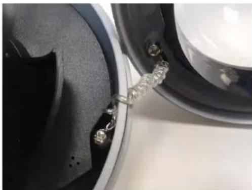
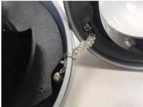
- Optional: Remove the camera dome from camera housing by removing the anti-drop chain. Or, leave the protective film on the dome and use care.
natural_image
Close-up of a speaker component with metal clamps and a metallic bracket, no visible text or symbols- Secure the back box on the mounting bracket.
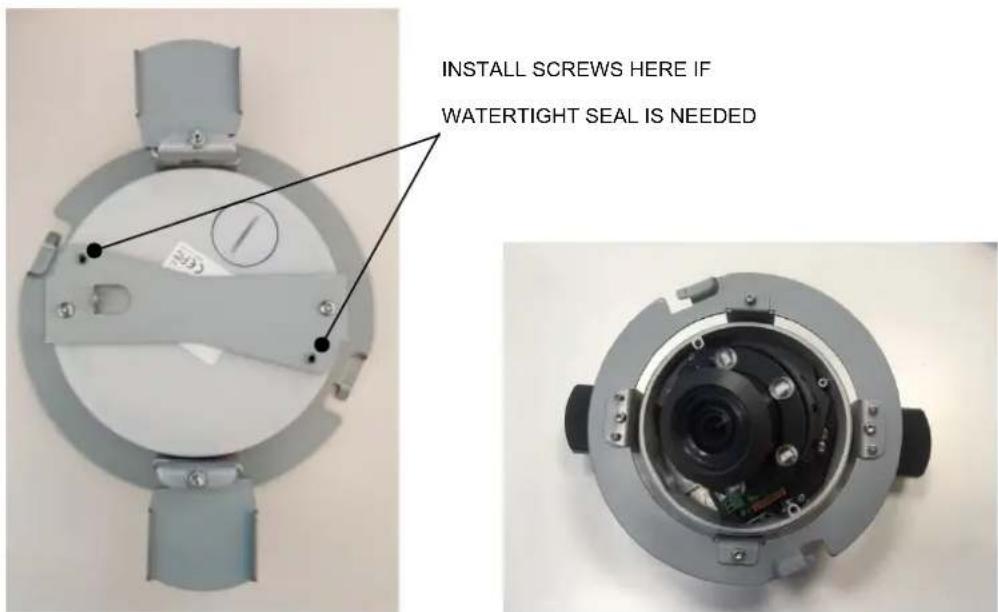
- Determine the mounting location in the ceiling.
- Use the template to mark the hole on the wall, ceiling, or ceiling tile.
- Cut the hole for the camera.
- Pull the wiring through the hole.
- Move the conduit plug to side or top where needed to use the other hole for wire entry. Tighten the plug.
- Install the back box as follows:
a. Attach and seal the conduit as needed.
b. If using conduit (not supplied): Feed wires into the back box, and plug camera in.
c. Fold the rubber holders inside to clear the hole.
d. Push the back box through the hole.
e. Rotate the screws clockwise to secure the bracket on the ceiling.
natural_image
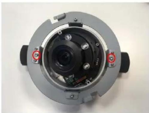
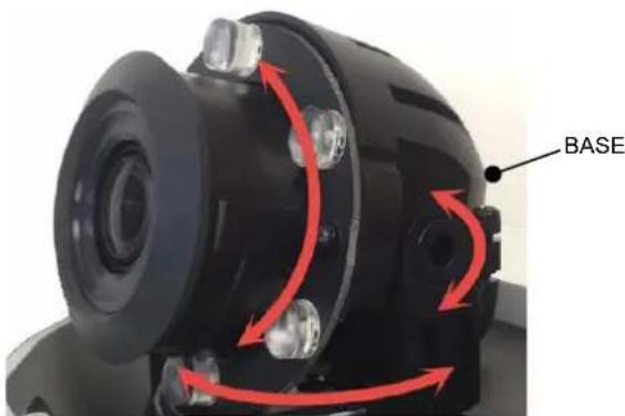
Top-down view of a mechanical device with internal components and mounting holes (no visible text or symbols)- Adjust the angle of lens by pan and tilt. Grasp the base of the lens assembly to adjust.
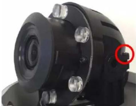
- Tighten the locking screw to secure the camera module position.
natural_image
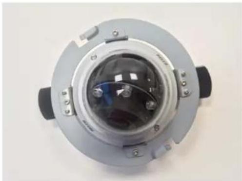
Close-up of a black mechanical component with a red circular highlight on the side (no visible text or symbols)- Secure the anti-drop chain, put on the dome cover, and tighten the dome cover.
natural_image
Top-down view of a circular mechanical device with central transparent dome and mounting brackets (no visible text or symbols)- Put on the trim ring and rotate it clockwise to secure the trim ring on the bracket.
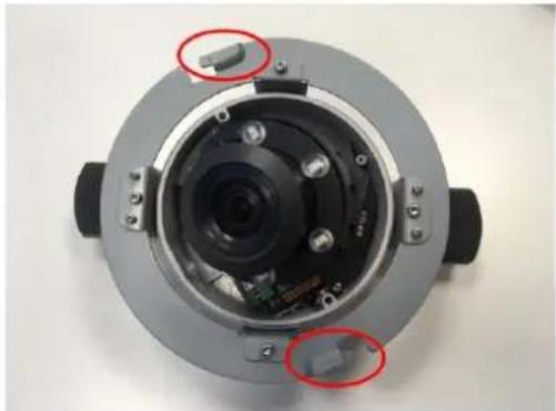
natural_image
Top-down view of a mechanical camera module with visible internal components and two red-circled highlights (no text or symbols)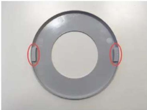
natural_image
Circular metallic ring component with two red-circled features on the side (no text or symbols visible)Pendant: Indoor and Environmental with IMEPM-I or IMEPM-E and WMVE-SR or WMVE-SW
Supplied Parts List
Qty Description
1 Pendant cap
2 M4x8 mechanical screws
Installation Guide
- Optional: Remove the camera dome from camera housing by removing the anti-drop chain.
natural_image
Close-up of a speaker component with metal clamps and a metallic bracket, no visible text or symbols-
Put the conduit plug on the side of the camera box.
-
Apply grease or Teflon tape to the pendant threads.
-
Put the wiring through the hole on the top of the pendant cap into the camera.
-
Screw on the pendant to the pipe or support arm.
-
Add the support arm if purchased. Refer to the WMVE-SR and WMVE-SW installation manual on pelco.com for installing the wall mount arm.
WMVE-SR AND WMVE-SW WALL MOUNT ARM
natural_image
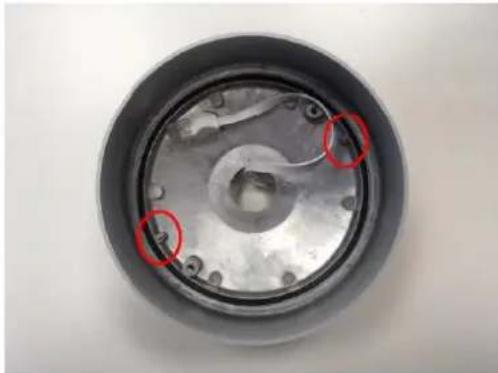
White plastic mechanical bracket with mounting holes and a small screw (no text or symbols visible)- Place the camera back box or full camera into the pendant cap and adjust the camera back box by using the self-positioning pillars in the pendant cap. Twist until it snaps fully in. Secure the 2 M4 screws.
natural_image
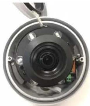
Close-up of a mechanical component with circular features and red-circled highlights (no text or symbols visible)- Replace the camera on the back box (if removed for installation ease).
natural_image
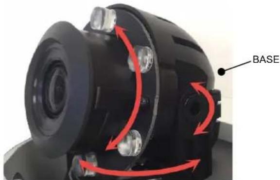
Close-up of a camera lens assembly with visible internal components and mounting bracket (no text or symbols)- Adjust the angle of lens by pan and tilt by grasping the base.
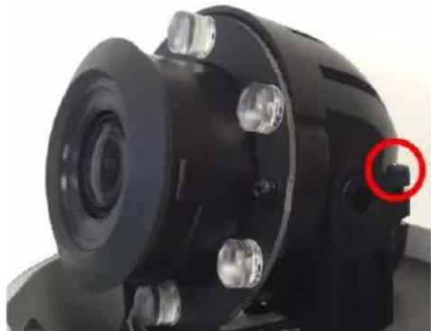
- Tighten the locking screw to secure the camera module position.
natural_image
Close-up of a black mechanical component with a red circular highlight on the side (no visible text or symbols)- Secure the anti-drop chain, put on the dome cover, and tighten the dome cover.
natural_image
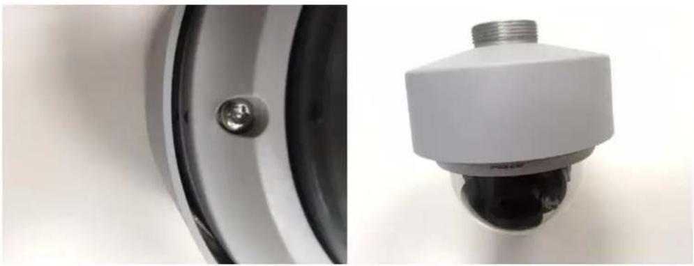
Close-up of a metallic wall-mounted security camera component and its 3D rendering (no text or symbols visible)Surface and Type 4X Mount: Environmental with IMEEBAP-E Installation Guide
NOTE: The environmental camera is weather tight, rated IP66 if installed directly to a surface. So, this mounting plate is optional. However, to comply with Type 4X outdoor rating, one must install the Type 4X mounting plate. (The Type 4X plate has a dual function to mount to junction boxes, so you can ignore the additional holes if not installing to a junction box.
-
Install the Type 4X Electrical Adapter Plate (plate) on the surface or Type 4X electrical box and secure the screws.
-
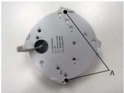
Prepare the wire entry holes through the plate and camera box as follows:
a. Remove the conduit plug if required and move to the hole not used.
natural_image
Interior view of a mechanical device showing internal components and a circular housing (no text or symbols visible)-
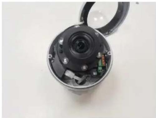
Remove the dome cover from the camera (optional).
-
Install the camera to the plate.
-
Pull the wire through the conduit hole into the camera.
-
Mount the plate/camera to the surface using the holes marked "A" in the illustration above.
-
Connect and seal the conduit.
-
Adjust the angle of lens by pan and tilt by the base.
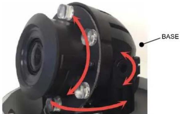
- Tighten the locking screw to secure the camera module position.
natural_image
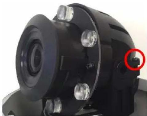
Close-up of a mechanical component with a red circle highlighting a small feature (no visible text or symbols)- Install the dome lanyard if removed and then the dome cover and tighten the dome cover screws.
natural_image
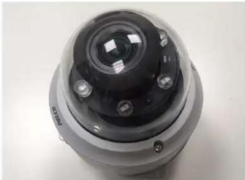
Close-up of a metallic spherical security camera with lens and mounting holes (no visible text or symbols)Surface Mount: Indoor
Installation Guide
- Prepare the wire entry holes through the plate and camera box as follows: a. Remove the conduit plug if required and move to the hole not used.
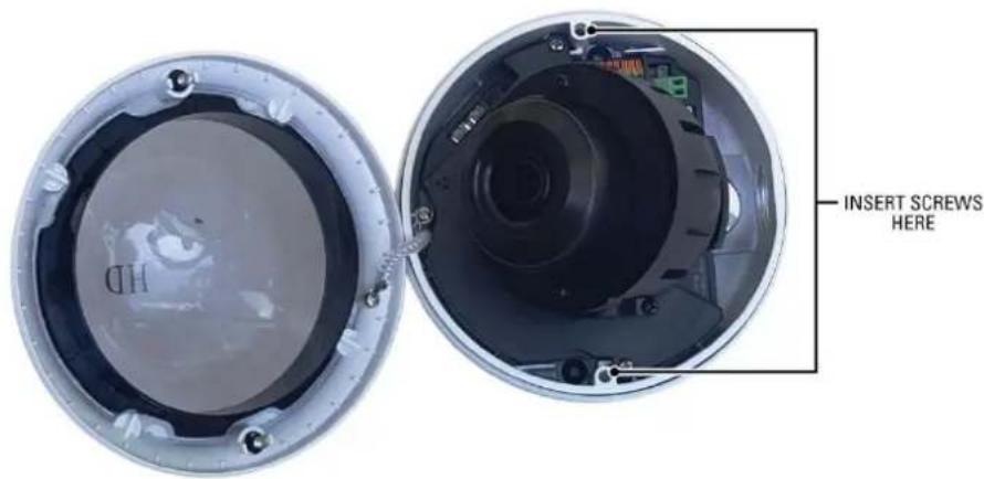
- Remove the dome cover from the camera (optional).
- Pull the wire through the conduit hole into the camera.
- Mount the plate/camera to the surface.
- Adjust the angle of lens by pan and tilt by the base.
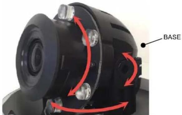
- Tighten the locking screw to secure the camera module position.
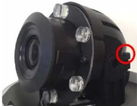
natural_image
Close-up of a black mechanical component with a red circular annotation highlighting a small feature (no visible text or symbols)- Install the dome lanyard if removed and then the dome cover and tighten the dome cover screws.
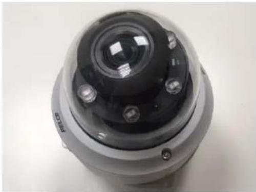
natural_image
Close-up of a camera lens mounted on a spherical device (no visible text or symbols)Wall Mount: Indoor with IMEPMB-I
Supplied Parts List
Qty Description
1 Wall mount bracket
2 Plastic screw anchors
2 M4x25 self-tapping screws
2 M4x8 mechanical screws
Installation Guide
- Place the wall mount bracket at the installation location.
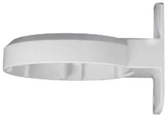
natural_image
3D rendered white plastic object with a curved top and side protrusion (no text or symbols)- Prepare the wire entry holes through the wall mount bracket and camera box. Move the plug if necessary.
- Install the camera to the wall mount bracket using 2 M4 screws.
- Adjust the angle of lens by pan and tilt.
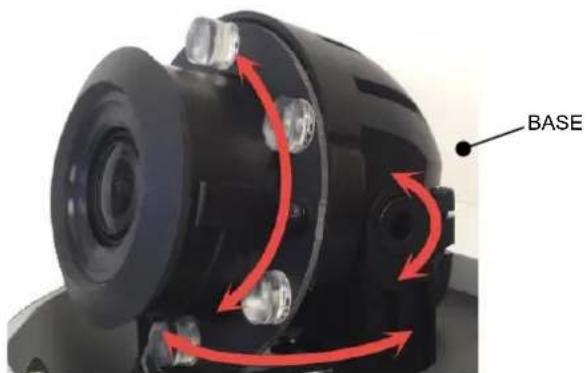
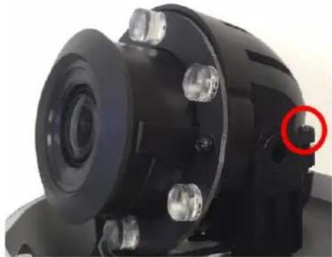
- Tighten the locking screw to secure the camera module position.
natural_image
Close-up of a black mechanical component with a red circle highlighting a small feature (no visible text or symbols)- Install the dome cover and tighten the dome cover.
Positioning the Camera
- Pan Adjustment (A): Rotate the lens base until you are satisfied with the field of view. Note that the side conduit hole of the lower case is the point where the camera lens shouldn't be rotated over.
- Horizontal Rotation (B): Rotate 3D assembly in the lens base, but do not turn assembly more than 355^ as this may cause the internal cables to be twisted, disconnected, or broken.
- Tilt Adjustment (C): Lift to open the inner liner, and tilt the camera lens to your desired angle. Restore the inner liner back to its default position after adjustment.
NOTE: Limitation for three axes position: Pan range: 355°, Rotate range: 340°, Tilt range: 75°
Cable Terminations
Ethernet Wiring Requirement for PoE
Connect a Cat5 cable or higher (Cat5e, Cat6) cable (not supplied) to the RJ-45 network connector. The 8-pin port includes video over Ethernet, and PoE for the camera. PoE injects power over the same cabling that carries the network data, eliminating the need for a separate power supply. This simplifies the installation and operation of the camera without affecting network performance.
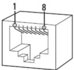
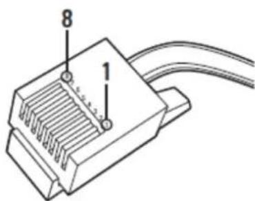
Table 1 Pin Definition
| PoE Mode A | PoE Mode B | ||
| Pin | Function | Pin | Function |
| 1 | TX+, PoE 1-2 | 1 | TX+ |
| 2 | TX-, PoE 1-2 | 2 | TX- |
| 3 | RX+, PoE 3-4 | 3 | RX+ |
| 4 | Not used | 4 | PoE 1-2 |
| 5 | Not used | 5 | PoE 1-2 |
| 6 | RX-, PoE 3-4 | 6 | RX- |
| 7 | Not used | 7 | PoE 3-4 |
| 8 | Not used | 8 | PoE 3-4 |
Alarm/Relay/Audio Port
The 9-pin Alarm/Relay/Audio port has the following pins and pin assignments
Table 2 Pin Descriptions for Alarm/Relay/Audio Port
| No. | Connector | Pin | Definition | Remarks |
| 1 | Alarm & Audio I/O | 1 | Audio In L | Audio In |
| 2 | Audio In R | |||
| 3 | GND | |||
| 4 | Audio Out L | Audio Out | ||
| 5 | Audio Out R | |||
| 6 | Alarm Out + | Alarm connection | ||
| 7 | Alarm Out - | |||
| 8 | Alarm In + | |||
| 9 | Alarm In - |
IP Address Settings
If the camera is connected to a Dynamic Host Configuration Protocol (DHCP) network and DHCP is set to On, the server automatically assigns an IP address to the camera. The default setting for the camera is DHCP On. To set the camera's IP address manually, set DHCP to Off.
NOTE:
When DHCP is on, but a DHCP server cannot be found:
- Next Gen Sarix Enhanced cameras will support two IP addressing schemes: 169.254.x.x and 192.168.0.x (starting from 192.168.0.20).
The default IP address on subnet mask 255.255.0.0 is automatically assigned as 169.254.x.y where x and y will take a value from 0 to 255 randomly. Please note cameras on the same subnet will not be assigned the same IP address to avoid IP conflicts.
The device defaults to an address of 192.168.0.20 on a 255.255.255.0 subnet. If 192.168.0.20 is already in use on the network, the Sarix device will increment the address by one until it finds an unused address (for example, 192.169.0.21 if 192.168.0.20 is in use).
Logging On to the Camera
After logging on to the camera, you can view video from the Web user interface.
- Open the Web browser.
- Type the camera's IP address in the browser address bar, and then press Enter.
NOTE: If you do not know the camera's IP address, you can locate it using the Pelco Device Utility software. - To access the device in its initial out-of-the-box state, you will be able to set the initial administrator account password.
NOTE: The initial out-of-the-box state is also called "Factory Default Status."
- Click Log In.
Pelco Troubleshooting Contact Information
If the instructions provided fail to solve your problem, contact Pelco Product Support at 1-800-289-9100 (USA and Canada) or +1-559-292-1981 (international) for assistance. Be sure to have the serial number available when calling.
Do not try to repair the unit yourself. Leave maintenance and repairs to qualified technical personnel only.

by Schneider Electric
Pelco by Schneider Electric
3500 Pelco Way Clovis, California 93612 USA
(800) 289-9100 Tel (800) 289-9150 Fax
+1 (559) 292-1981 International Tel
+1 (559) 348-1120 International Fax
www.pelco.com
Pelco, the Pelco logo, and other trademarks associated with Pelco products referred to in this publication are trademarks of Pelco, Inc. or its affiliates. ONVIF and the ONVIF logo are trademarks of ONVIF Inc. All other product names and services are the property of their respective companies. Product specifications and availability are subject to change without notice.
© Copyright 2015, Pelco, Inc. All rights reserved.
- Next Gen Sarix® Enhanced IME Series Mini Dome Cameras
- Contents
- Important Notices
- Regulatory Notices
- Radio and Television Interference
- Korean Class A EMC
- UL Safety Notices
- Introduction
- Models
- Recommended Mounts
- Optional Accessories
- Getting Started
- NOTES:
- Surface Mount Models
- Supplied Parts List
- Qty Description
- (Outdoor Cameras Only)
- User-Supplied Parts List
- Product Overview
- Installation
- Installing the Mount
- In-Ceiling: Indoor and Environmental with IMEICM-I or IMEICM-E
- Installation Guide
- Pendant: Indoor and Environmental with IMEPM-I or IMEPM-E and WMVE-SR or WMVE-SW
- Surface and Type 4X Mount: Environmental with IMEEBAP-E Installation Guide
- Surface Mount: Indoor
- Wall Mount: Indoor with IMEPMB-I
- Positioning the Camera
- Cable Terminations
- Ethernet Wiring Requirement for PoE
- Alarm/Relay/Audio Port
- IP Address Settings
- NOTE:
- Logging On to the Camera
- Pelco Troubleshooting Contact Information
- Pelco by Schneider Electric
Brand : Pelco
Model : Sarix Enhanced IME222-1RS
Category : Security Camera