CRMR60-D4 - Fridge Hoshizaki - Free user manual and instructions
Find the device manual for free CRMR60-D4 Hoshizaki in PDF.

User questions about CRMR60-D4 Hoshizaki
0 question about this device. Answer the ones you know or ask your own.
Ask a new question about this device
Download the instructions for your Fridge in PDF format for free! Find your manual CRMR60-D4 - Hoshizaki and take your electronic device back in hand. On this page are published all the documents necessary for the use of your device. CRMR60-D4 by Hoshizaki.
USER MANUAL CRMR60-D4 Hoshizaki
Refrigerated Kitchen Equipment
Models
Undercounter
Worktop
Prep Table
WARNING
Only qualified service technicians should install and service the appliance. To obtain the name and phone number of your local Hoshizaki Certified Service Representative, visit www.hoshizaki.com. No installation or service should be undertaken until the technician has thoroughly read this Instruction Manual. Likewise, the owner/manager should not proceed to operate the appliance until the installer has instructed them on its proper operation. Failure to install, operate, and maintain the appliance in accordance with this manual may adversely affect safety, performance, component life, and warranty coverage. Proper installation is the responsibility of the installer. Product failure or property damage due to improper installation is not covered under warranty.
Hoshizaki provides this manual primarily to assist qualified service technicians in the installation, maintenance, and service of the appliance.
Should the reader have any questions or concerns which have not been satisfactorily addressed, please call, send an e-mail message, or write to the Hoshizaki Technical Support Department for assistance.
Phone: 1-800-233-1940; (770) 487-2331
Fax: 1-800-843-1056; (770) 487-3360
E-mail: techsupport@hoshizaki.com
618 Highway 74 South
Peachtree City, GA 30269
Attn: Hoshizaki Technical Support Department
Web Site: www.hoshizaki.com
NOTE: To expedite assistance, all correspondence/communication MUST include the following information:
- Model Number ____
- Serial Number
- Complete and detailed explanation of the problem.
IMPORTANT
This manual should be read carefully before the appliance is installed and operated. Read the warnings and guidelines contained in this manual carefully as they provide essential information for the continued safe use and maintenance of the appliance. Retain this manual for any further reference that may be necessary.
CONTENTS
Important Safety Information 4
I. Installation Instructions 8
A. Location 8
B. Checks Before Installation....9
C. Setup....9
D. Solid Door Reversal.... 16
E. Door/Drawer Location Reversal 19
F. Glass Door Reversal 29
G. Electrical Connection....30
H. Final Checklist.... 31
II. Operating Instructions....32
A. Important Notes About Usage....32
B. Startup 35
C. Controls and Adjustments 35
1. Temperature Reading....35
2. Adjusting the Temperature 35
D. Defrost....36
1. Undercounter and Worktop Refrigerators.... 36
2. Prep Table Refrigerators and Undercounter and Worktop Freezers 36
E. Food Storage....37
F. Safety Devices 38
G. Cooling Performance 38
H. Cabinet Condensation 38
III. Cleaning and Maintenance Instructions....39
A. Cleaning 39
1. Exterior....39
2. Cabinet Interior 39
3. Door/Drawer Gaskets 39
4. Shelves 39
5. Glass Door....39
6. Drawers 40
7. Worktop (Worktop Models) 40
8. Cutting Board (Prep Table Models) 40
9. Rail, Rail Hood, and Rail Cover (Prep Table Models) 41
10. Spill Guard 41
B. Maintenance....41
IV. Preparing the Appliance for Periods of Non-Use 42
V. Disposal 43
Important Safety Information
Throughout this manual, notices appear to bring your attention to situations which could result in death, serious injury, damage to the appliance, or damage to property.
| ⚠ DANGER | Indicates a hazardous situation that, if not avoided, will result in death or serious injury. |
| ⚠ WARNING | Indicates a hazardous situation that, if not avoided, could result in death or serious injury. |
| NOTICE | Indicates a situation that, if not avoided, could result in damage to the appliance or property. |
| IMPORTANT | Indicates important information about the use and care of the appliance. |
DANGER
Risk of Fire or Explosion
Flammable Refrigerant Used
- Follow handling instructions carefully in compliance with U.S. government regulations.
- Do not use mechanical devices to defrost.
- Do not puncture refrigerant tubing. Risk of fire or explosion due to puncture of refrigerant tubing; follow handling instructions carefully.
- Component parts shall be replaced with like components.
- Servicing shall be done by factory authorized service personnel to minimize the risk of possible ignition due to incorrect parts or improper service.
- Consult instruction manual/service manual before attempting to install or service this product. All safety precautions must be followed.
- Dispose of properly in accordance with federal or local regulations.
- Do not place any potential ignition sources in or near the appliance.
The appliance should be destined only to the use for which it has been expressly conceived. Any other use should be considered improper and therefore dangerous. The manufacturer cannot be held responsible for injury or damage resulting from improper, incorrect, and unreasonable use. Failure to install, operate, and maintain the appliance in accordance with this manual will adversely affect safety, performance, component life, and warranty coverage. To reduce the risk of death, electric shock, serious injury, or fire, follow basic precautions including the following:
- Only qualified service technicians should install and service the appliance.
- Wear appropriate personal protective equipment (PPE) when servicing the appliance.
- The appliance must be installed in accordance with applicable national, state, and local codes and regulations.
- Appliance is heavy. Use care when lifting or positioning. Work in pairs when needed to prevent injury or damage. Do not lift using the top section or the doors/drawers.
- To reduce the risk of electric shock, do not touch the plug with damp hands.
- Unplug the appliance before servicing.
- The appliance requires an independent power supply of proper capacity. See the nameplate for electrical specifications. Failure to use an independent power supply of proper capacity can result in a tripped breaker, blown fuse, damage to existing wiring, or component failure. This could lead to heat generation or fire.
• THE APPLIANCE MUST BE
GROUNDED. The appliance is equipped with a NEMA 5-15 three-prong grounding plug ☐ to reduce the risk of potential shock hazards. It must be plugged into a properly grounded, independent 3-prong wall outlet. If the outlet is a 2-prong outlet, it is your personal responsibility to have a qualified electrician replace it with a properly grounded, independent 3-prong wall outlet. Do not remove the ground prong from the power cord and do not use an adapter plug. Failure to follow these instructions may result in death, electric shock, or fire.
- Do not use an extension cord.
- Do not use an appliance with a damaged power cord. The power cord should not be altered, jerked, bundled, weighed down, pinched, or tangled. Such actions could result in electric shock or fire. To unplug the appliance, be sure to pull the plug, not the cord, and do not jerk the cord.
- The GREEN ground wire in the factory-installed power cord is connected to the appliance. If it becomes necessary to remove or replace the power cord, be sure to connect the power cord's ground wire.
- Do not splash, pour, or spray water directly onto or into the appliance. This might cause short circuit, electric shock, corrosion, or failure.
- Do not make any alterations to the appliance. Alterations could result in electric shock, injury, fire, or damage to the appliance.
- The appliance is not intended for use by persons (including children) with reduced physical, sensory, or mental capabilities, or lack of experience and knowledge, unless they have been given supervision or instruction concerning use of the appliance by a person responsible for their safety.
⚠ WARNING, continued
- Children should be properly supervised around the appliance.
- Do not climb, stand, or hang on the appliance or doors/drawers or allow children or animals to do so. Do not climb into the appliance or allow children or animals to do so. Death or serious injury could occur or the appliance could be damaged.
- Be careful not to pinch fingers when opening and closing the doors/drawers or rail cover (prep table models) or when handling food pans. Be careful when opening and closing the doors/drawers or rail cover when children are in the area.
- Open and close the doors/drawers and rail cover (prep table models) with care. Opening the doors/drawers or rail cover too quickly or forcefully may cause injury or damage to the appliance or surrounding equipment.
- Do not use combustible spray or place volatile or flammable substances in or near the appliance. They might catch fire.
- Keep the area around the appliance clean. Dirt, dust, or insects in the appliance could cause harm to individuals or damage to the equipment.
- Do not throw anything onto the shelves or load any single shelf with more than 120 lb. (54.5 kg) of product. They might fall off and cause injury.
- Do not load any single drawer with more than 75 lb. (34 kg) of product. Depending on the weight of product in the drawers, secure the unit as necessary to prevent it from overturning. Do not open more than one drawer at a time.
-
The appliance is designed only for temporary storage of food. Employ sanitary methods. Use for any other purposes (for example, storage of chemicals or medical supplies such as vaccine and serum) could cause deterioration of stored items.
-
Do not block air inlets or outlets, otherwise cooling performance may be reduced.
- Do not tightly pack the cabinet. Allow some space between items to ensure good air flow. Also allow space between items and interior surfaces.
- Do not put warm or hot foods in the cabinet. Let them cool first, or they will raise the cabinet temperature and could deteriorate other foods in the cabinet or overload the appliance.
- Food storage and handling must comply with applicable codes and regulations.
- All foods should be wrapped in plastic film or stored in sealed containers. Otherwise foods may dry up, pass their smells onto other foods, cause frost to develop, result in poor appliance performance, or increase the likelihood of cross-contamination. Certain dressings and food ingredients, if not stored in sealed containers, may accelerate corrosion of the evaporator, resulting in failure.
- Do not store items near air outlets. Otherwise, items may freeze up and crack or break causing a risk of injury or contamination of other food.
⚠ WARNING, continued
Additional Warnings for Prep Table Models
- The entire rail must always be covered by rail dividers and pans (1/6 size, up to 6" (15 cm) deep). Otherwise, the appliance will not cool properly.
- Use only 1/6 size pans up to 6" (15 cm) deep. Do not use damaged pans.
- Ingredients must be pre-chilled to 37°F (3°C) or less before placing in rail.
- Keep the rail cover closed when not actively preparing food.
- The rail is for keeping ingredients cool while preparing food. If not actively preparing food for a long period such as overnight, seal pans with plastic wrap in addition to closing the rail cover. Depending on conditions, the cabinet temperature setting may need to be adjusted to prevent items from freezing. Alternatively, seal ingredients and store them in a refrigerator or freezer.
NOTICE
- Protect the floor when moving the appliance to prevent damage to the floor.
- Keep ventilation openings, in the appliance enclosure or in the built-in structure, clear of obstruction. Do not place anything on top of the appliance in an undercounter installation. There must be at least 1.5" (4 cm) overhead clearance for proper ventilation. The factory-installed rear bumpers must be in place to ensure proper rear clearance. Blockage of airflow could negatively affect performance and damage the appliance.
- Do not allow the appliance to bear any outside weight.
- To prevent deformation or cracks, do not spray insecticide onto the plastic parts or let them come into contact with oil.
- To avoid damage to the gasket, use only the door/drawer handle when opening and closing.
- To avoid damage to the top seal, do not lift the appliance by the top panel or remove the top panel.
Additional Notice for Prep Table Models
- Do not place anything on top of the rail hood or rail cover and do not lift the appliance by the rail hood or rail cover. The rail hood and rail cover are not designed to bear any outside weight.
I. Installation Instructions
WARNING
- The appliance must be installed in accordance with applicable national, state, and local regulations.
- Appliance is heavy. Use care when lifting or positioning. Work in pairs when needed to prevent injury or damage. Do not lift using the top section or the doors/drawers.
- Do not tilt the appliance more than 45^ .
A. Location
WARNING
- The appliance is not intended for outdoor use.
- Undercounter and Worktop: Certified to maintain NSF temperatures up to 100^ (38°C).
- Prep Tables: Certified to maintain NSF temperatures between 45^ to 86^ (7°C to 30^ ) and engineered to maintain NSF temperatures up to 100^ (38°C).
- Operation of the appliance, for extended periods, outside of this normal temperature range may affect appliance performance.
For best operating results:
- The appliance should not be located next to ovens, grills, or other high heat producing equipment.
- The location should provide a firm and level foundation for the appliance.
- The appliance should not be located in a corrosive environment.
- The factory-installed rear bumpers must be in place to ensure proper rear clearance. For undercounter and worktop models, a minimum of 1.5" (4 cm) overhead clearance should be provided for proper ventilation. For prep table models, a minimum of 10" (25 cm) clearance above the rail hood should be provided to allow the rail cover to open.
B. Checks Before Installation
WARNING
Refer to the nameplate for electrical specifications. The nameplate is located on the right side wall of the cabinet interior. For more electrical connection details, see "I.E. Electrical Connection." We reserve the right to make specification and design changes without prior notice.
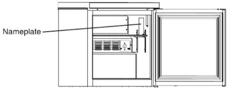
text_image
Nameplate- Visually inspect the exterior of the shipping package and immediately report any damage to the carrier. Upon opening the package, any concealed damage should also be immediately reported to the carrier.
- Remove the shipping carton, tape, and packing material. Also remove the protective plastic film from both the exterior panels and the interior door/drawer panel. If the appliance is exposed to the sun or to heat, remove the film after the appliance cools.
- Remove all accessory containers before discarding the packing materials. Dispose of all packing materials in a proper and environmentally responsible manner.
- Check for missing or damaged accessories.
C. Setup
1. Caster Installation, Leveling the Appliance, and Door Alignment
a) Caster Installation
1) Move as close to the final location as possible.
2) Remove the 2 bolts securing the appliance to the pallet, then remove the appliance from the pallet. Block the appliance securely at a height of 8" (20 cm) off the floor. Do not lay the appliance down.
3) Attach the casters to the bottom of the appliance. Locking casters should be attached to the front of the appliance. See Fig. 1.
Note: For UR_WR_SR48A(-xx), rear caster brackets must be installed with the rear casters as illustrated. See Fig. 2.
NOTICE! Ensure casters are completely threaded into appliance and tight.
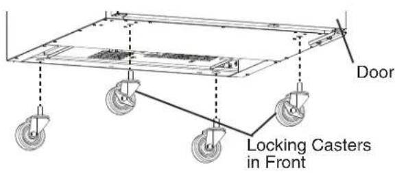
text_image
Door Locking Casters in FrontFig. 1
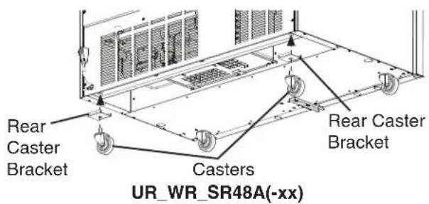
text_image
Rear Caster Bracket Casters Rear Caster Bracket UR_WR_SR48A(-xx)Fig. 2
b) Leveling the Appliance and Door Alignment
After installing the casters, lower the appliance to the floor and check the level of the appliance and the alignment of the doors. If the appliance is out of level or the doors are out of alignment, follow the steps below. Otherwise, continue to the next section.
1) Secure the doors. Raise and block the appliance. Make sure the appliance is stable.
2) Unscrew the appropriate caster to the approximate desired height. See Fig. 3.
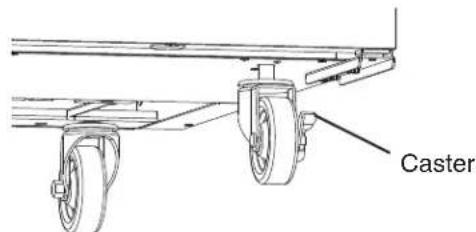
text_image
CasterFig. 3
3) Position the necessary number of shim plates in place (no more than 3 per caster). If using more than one shim plate, rotate each additional shim plate 90^ from the adjoining shim plate so that the slots are not aligned. See Fig. 4.
Note: Do not shim the rear of the appliance higher than the front as this could affect door performance.
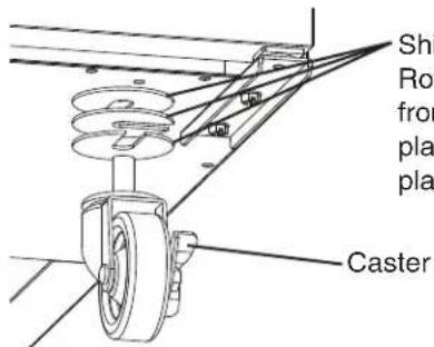
text_image
Ship Rotor from pla pla CasterShim Plates
Rotate each shim plate 90° from the adjoining shim plate. Maximum of 3 shim plates per caster.
Fig. 4
4) Tighten the caster. See Fig. 5. NOTICE! Make sure the caster is tight and no slack is left between the caster, shim plates, and appliance.
5) Repeat the procedure for other casters as needed.
6) Lower the appliance to the floor.
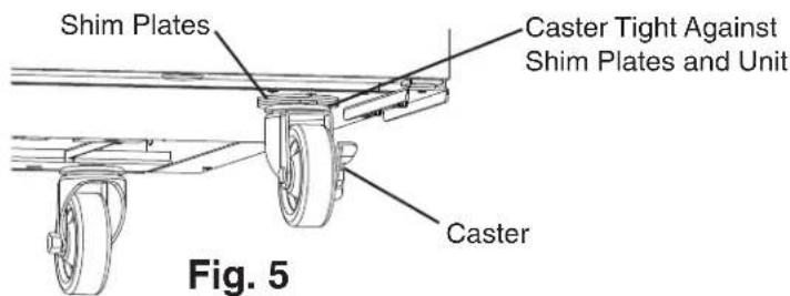
text_image
Shim Plates Caster Tight Against Shim Plates and Unit Caster Fig. 52. Check the Refrigeration Circuit
- Visually check that the refrigerant lines do not rub or touch other lines or surfaces and that the condenser fan blade turns freely.
- Check that the compressor is securely attached.
3. Position the Appliance and Lock the Front Casters
The front casters on the appliance are lockable. After positioning the appliance in its final location, lock the front casters.
4. Install the Shelves
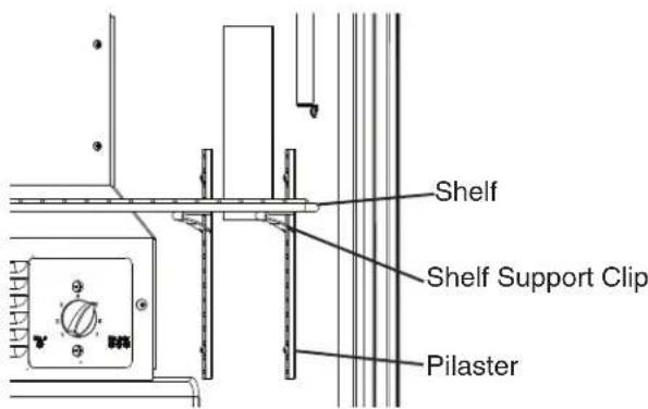
1) For each shelf, place the shelf support clips into the pilasters at the desired height (4 shelf support clips per shelf). See Fig. 6.
2) Place the shelves in position on the support clips.
text_image
Shelf Shelf Support Clip PilasterFig. 6
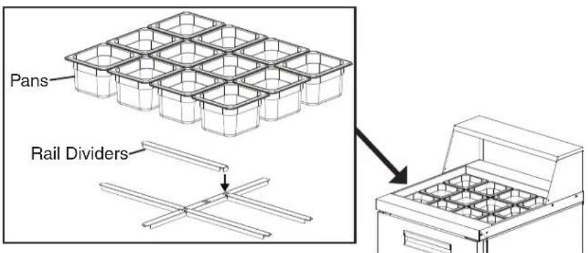
5. Install the Rail Dividers and Pans (Prep Table Models)
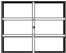
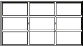
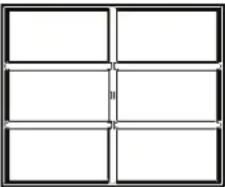
Install the rail dividers and 1/6 size pans included with the appliance. See Fig. 7 and the table below. The entire rail must always be covered by rail dividers and pans. Otherwise, the appliance will not cool properly. Use pans with a depth of up to 6" (15 cm). Do not use damaged rail dividers or pans.
Fig. 7
text_image
Pans Rail DividersRail Divider Layout
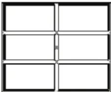
| -8 Models | |
SR27A-8 SR48A-8, SR60A-8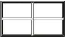 | 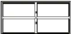 |
| Front-to-Back: HS-5187 (13-3/4"; 348 mm) Qty 1Side-to-Side: HS-5185 (12-1/2"; 319 mm) Qty 2 | Front-to-Back: HS-5188 (12-5/8"; 322 mm) Qty 1Side-to-Side: HS-5189 (13-5/8"; 346 mm) Qty 2 |
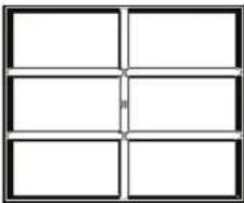
-10, -15M Models

natural_image
Pure geometric diagram with 3x3 grid lines and a vertical bar, no text or symbols presentFront-to-Back: HS-5187 (13-3/4"; 348 mm) Qty 2
Side-to-Side (Outer): HS-5185 (12-1/2"; 319 mm) Qty 1
Side-to-Side: HS-5186 (Center) (12-1/2"; 316 mm) Qty 1
Front-to-Back: HS-5184 (20-3/4"; 526 mm) Qty 2
Side-to-Side (Outer): HS-5185 (12-1/2"; 319 mm) Qty 2
Side-to-Side: HS-5186 (Center) (12-1/2"; 316 mm) Qty 2
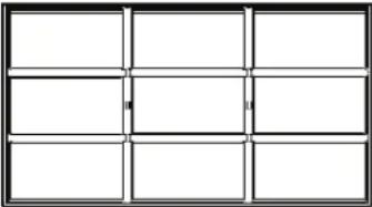
| -12, -12M Models | |
| SR48A-12, SR60A-12, SR72A-12 SR27A-12M, SR48A-12M, SR60A-12M | |
 |  |
| Front-to-Back: HS-5188 (12-5/8"; 322 mm) Qty 2Side-to-Side (Outer): HS-5189 (13-5/8"; 346 mm) Qty 2Side-to-Side (Center): HS-5190 (13-1/2"; 344 mm) Qty 1 | Front-to-Back: HS-5184 (20-3/4"; 526 mm) Qty 1Side-to-Side: HS-5185 (12-1/2"; 319 mm) Qty 4 |
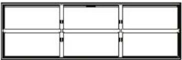
| Rail Divider Layout, continued |
| -16 Models |
SR60A-16, SR72A-16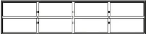 |
| Front-to-Back: HS-5188 (12-5/8"; 322 mm) Qty 3Side-to-Side (Outer): HS-5189 (13-5/8"; 346 mm) Qty 2Side-to-Side (Center): HS-5190 (13-1/2"; 344 mm) Qty 2 |
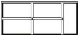
| -18, -18M Models | |
| SR72A-18 SR48A-18M, SR60A-18M, SR72A-18M | |
 |  |
| Front-to-Back: HS-5188 (12-5/8"; 322 mm) Qty 2Side-to-Side (Outer): HS-5191 (20-5/8"; 523 mm) Qty 2Side-to-Side (Center): HS-5192 (20-1/2"; 520 mm) Qty 1 | Front-to-Back: HS-5184 (20-3/4"; 526 mm) Qty 2Side-to-Side: HS-5185 (Outer) (12-1/2"; 319 mm) Qty 4Side-to-Side: HS-5186 (Center) (12-1/2"; 316 mm) Qty 2 |
| -24M Models | ||
| SR60A-24M, SR72A-24M | ||
 |  | |
| Front-to-Back: HS-5184 (20-3/4"; 526 mm) Qty 2Side-to-Side: HS-5185 (12-1/2"; 319 mm) Qty 8 | ||
| -30M Models | |
| SR72A-30M | |
 |  |
| Front-to-Back: HS-5184 (20-3/4"; 526 mm) Qty 3Side-to-Side (Outer): HS-5185 (12-1/2"; 319 mm) Qty 8Side-to-Side (Center): HS-5186 (12-1/2"; 316 mm) Qty 2 | |
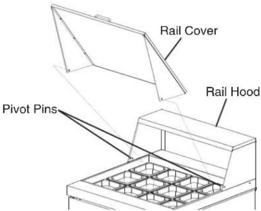
6. Install the Rail Cover (Prep Table Models)
1) Install and tighten the pivot pins, washers, and pivot screws on the rail hood with the pivot pin shafts facing inward towards the open rail area. See Fig. 8.
2) Models with Two Rail Covers: Install and tighten the pivot pins, washers, and pivot screws to the center hinge brackets, then secure the center hinge brackets using the 4×8 screws provided. See Fig. 9.
3) Install the rail cover(s) by squeezing in slightly on the rail cover side panels and aligning the holes in the rail cover side panels with the pivot pins. See Fig. 10.
Fig. 8
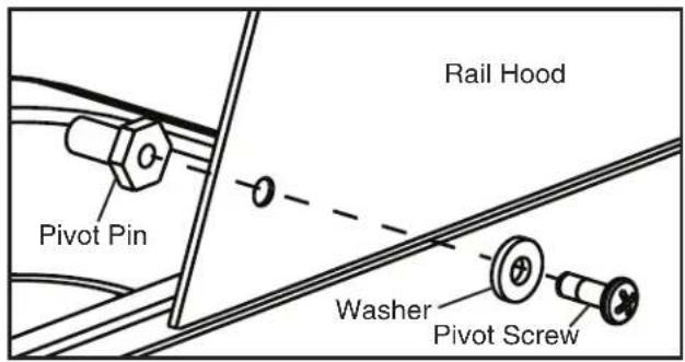
text_image
Rail Hood Pivot Pin Washer Pivot ScrewFig. 9
For Models with Two Rail Covers
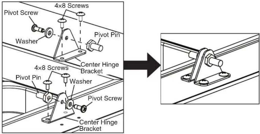
text_image
4x8 Screws Pivot Screw Washer Pivot Pin Center Hinge Bracket 4x8 Screws Pivot Pin Washer Pivot Screw Center Hinge BracketFig. 10
text_image
Rail Cover Rail Hood Pivot Pins7. Attach the Cutting Board Brackets and Cutting Board (Prep Table Models)
1) Remove the screws from the cutting board bracket mounting locations on the appliance. See Fig. 11a for Sandwich Top models and Fig. 11b for Mega Top models.
2) Use the screws removed in step 1 to attach the cutting board brackets.
3) Slide the cutting board into the cutting board brackets. WARNING! Make sure the cutting board brackets and cutting board are secure. Otherwise, the cutting board could come off and cause injury.
Fig. 11a
Sandwich Top Models
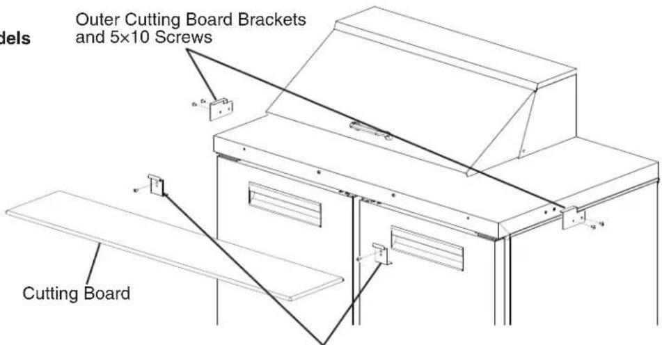
text_image
Outer Cutting Board Brackets and 5x10 Screws Cutting BoardInner Cutting Board Brackets and 5×12 Screws Quantity:
1 for SR27A and SR36A Sandwich Top Models
2 for SR48A Sandwich Top Models
3 for SR60A and SR72A Sandwich Top Models
Fig. 11b
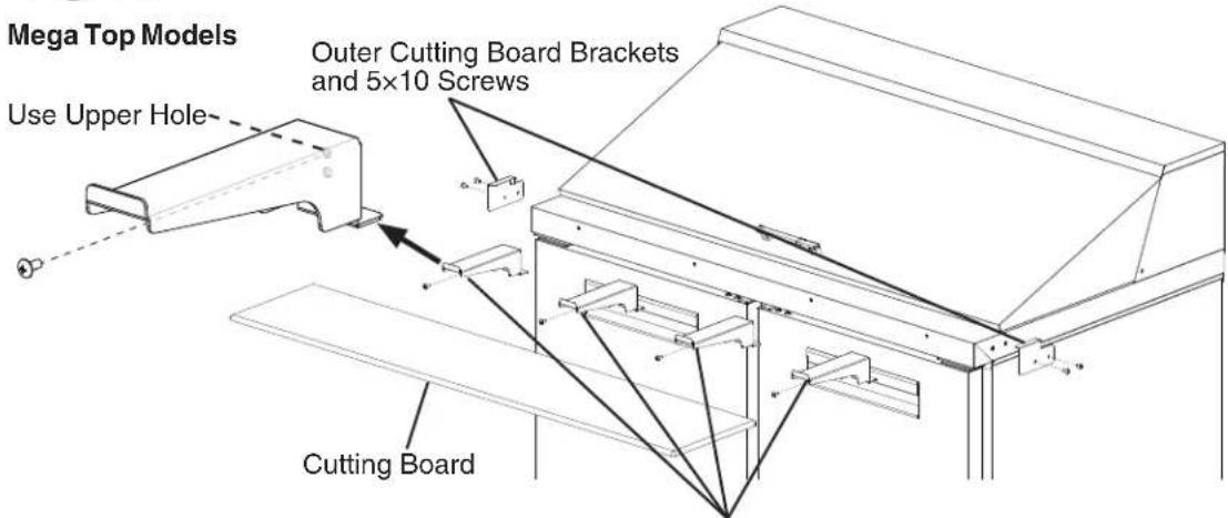
text_image
Mega Top Models Use Upper Hole Outer Cutting Board Brackets and 5×10 Screws Cutting BoardInner Cutting Board Brackets and 5×12 Screws Quantity:
2 for SR27A Mega Top Models
3 for SR36A Mega Top Models
4 for SR48A Mega Top Models
5 for SR60A and SR72A Mega Top Models
D. Solid Door Reversal
The appliance is provided with a cabinet design which, after being delivered to the installation location, permits changing of the door swing from left to right or right to left. To change the door swing, follow the steps below. Example shows change from right hinged to left hinged.
WARNING
- Wear proper PPE (personal protection equipment) when executing these procedures (safety glasses and gloves).
- Keep fingers away from edge of upper hinge bracket. Spring cartridge can cause the upper hinge bracket to move suddenly with extreme force.
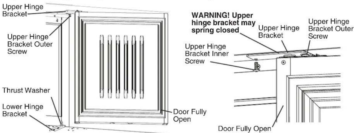
Door and Lower Hinge Removal and Relocation
1) Remove all items from the appliance. Make sure the appliance is unplugged from the electrical outlet. Move the appliance out for ease of access then lock the casters.
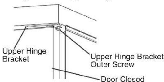
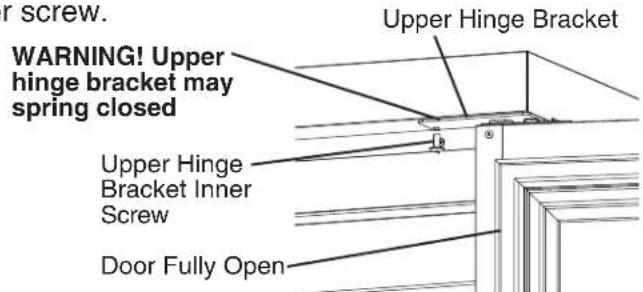
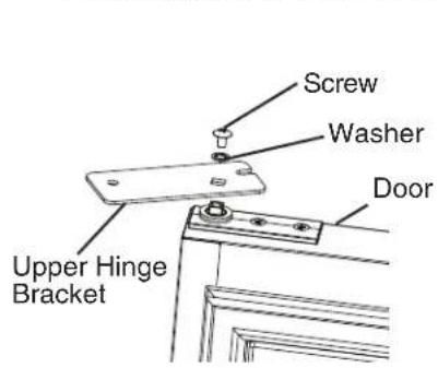
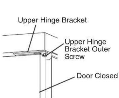
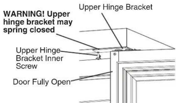
2) With the door closed, loosen, but do not remove, the upper hinge bracket outer screw. See Fig. 12. Next, open the door to the fully open position and remove the upper hinge bracket inner screw. See Fig. 13.
3) Slide the upper hinge bracket out from under the outer screw and remove the door. WARNING! Keep away from upper hinge bracket. Upper hinge bracket may spring closed.
4) Replace the upper hinge bracket inner screw in its original position and tighten, then tighten the upper hinge bracket outer screw. Upper Hinge Bracket
text_image
Upper Hinge Bracket Upper Hinge Bracket Outer Screw Door ClosedFig. 12
text_image
WARNING! Upper hinge bracket may spring closed Upper Hinge Bracket Upper Hinge Bracket Inner Screw Door Fully OpenFig. 13
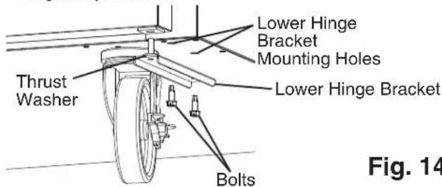
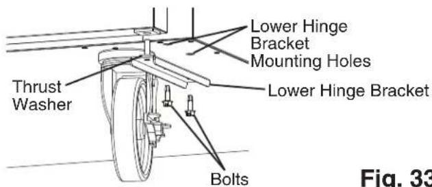
5) Remove the lower hinge bracket. See Fig. 14. Be sure to leave the thrust washer in place.
6) Clear the foam from the lower hinge bracket mounting holes prior to securing lower hinge bracket in its new location. Install the lower hinge bracket in its new location. Be sure the lower hinge bracket is pushed all the way in and the thrust washer is in its original position.
text_image
Lower Hinge Bracket Mounting Holes Thrust Washer Lower Hinge Bracket Bolts Fig. 14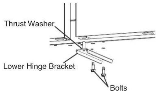
text_image
Thrust Washer Lower Hinge Bracket BoltsUpper Hinge Bracket Removal and Spring Cartridge Relocation
7) While preventing the upper hinge bracket from rotating, remove the upper hinge bracket from the spring cartridge. See Fig. 15. Note which side of the upper hinge bracket is facing up.
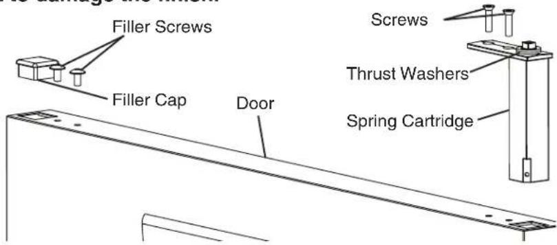
8) Remove the filler cap, filler screws, and spring cartridge. See Fig. 16. Leave the thrust washers in place on the spring cartridge. NOTICE! Spring cartridge may be difficult to remove. Be careful not to damage the finish.
text_image
Screw Washer Door Upper Hinge BracketFig. 15
text_image
Filler Screws Filler Cap Door Screws Thrust Washers Spring CartridgeFig. 16
9) Clear foam from the spring cartridge hole to allow for spring cartridge installation. See Fig. 17. Install the spring cartridge in its new location. Reinstall the filler cap and filler screws on the opposite side of the door.
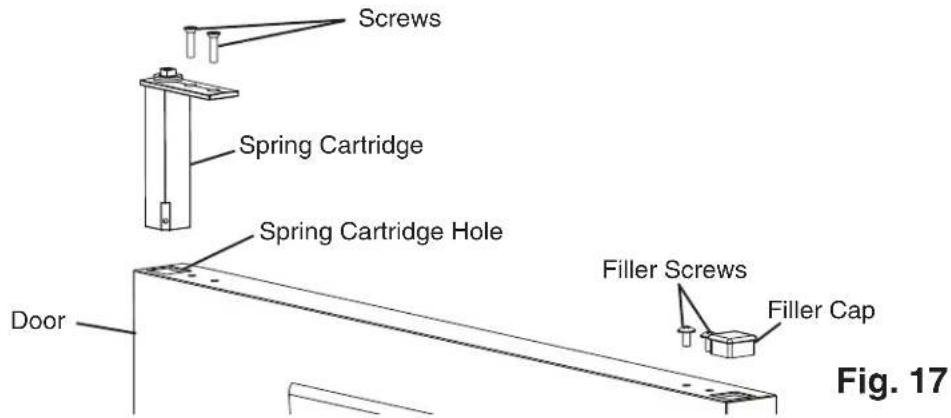
text_image
Screws Spring Cartridge Spring Cartridge Hole Door Filler Screws Filler Cap Fig. 17Lower Door Prep and Upper Hinge Bracket Relocation
10) Remove the filler cap and nylon bearing from the bottom of the door. See Fig. 18. Reinstall on the opposite side.
11) Make sure the thrust washers are in place on the spring cartridge, then flip the upper hinge bracket over from its original position and install onto the spring cartridge in the door open position. See Fig. 19. The upper hinge bracket should be positioned as shown.
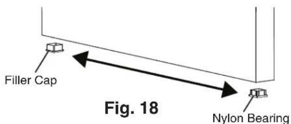
text_image
Filler Cap Fig. 18 Nylon Bearing
text_image
Screw Washer Upper Hinge Bracket Outer Screw Slot Upper Hinge Bracket Inner Screw Hole Upper Hinge Bracket Thrust Washers Inside of Door Fig. 19Door Installation
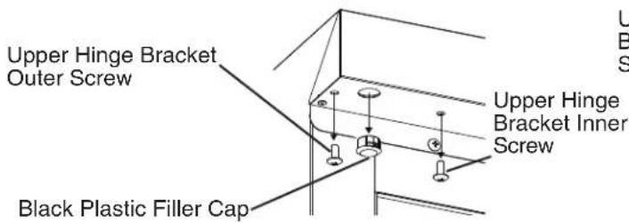
12) Remove the black plastic filler cap located from the hole above where the spring cartridge screw will line up. Note: The black plastic filler cap is not reusable.
13) Remove the upper hinge bracket screws from the new location and apply Loctite Threadlocker Blue 242 or 243 to the threads. Next, start the upper hinge bracket outer screw into the appliance. Rotate a few threads into the appliance; do not tighten the screw. See Fig. 20.
text_image
Upper Hinge Bracket Outer Screw Black Plastic Filler Cap Upper Hinge Bracket Inner Screw Fig. 20
text_image
Upper Hinge Bracket Outer ScrewFig. 20
14) Be sure the lower hinge bracket thrust washer is in place, then place the door on the lower hinge bracket in the fully open position. Slide the door upper hinge bracket outer slot onto the upper hinge bracket outer screw. See Fig. 21.
15) Install the upper hinge bracket inner screw and tighten.
text_image
Upper Hinge Bracket Outer Screw Upper Hinge Bracket Door Fully Open Lower Hinge Bracket Thrust Washer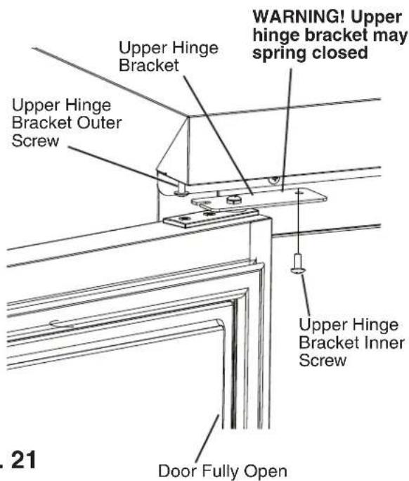
text_image
Upper Hinge Bracket Upper Hinge Bracket Outer Screw WARNING! Upper hinge bracket may spring closed Upper Hinge Bracket Inner Screw Door Fully Open . 21Fig. 21
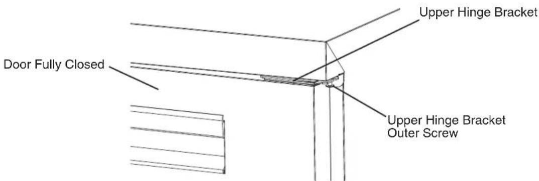
16) Close the door and tighten the upper hinge bracket outer screw.
See Fig. 22.
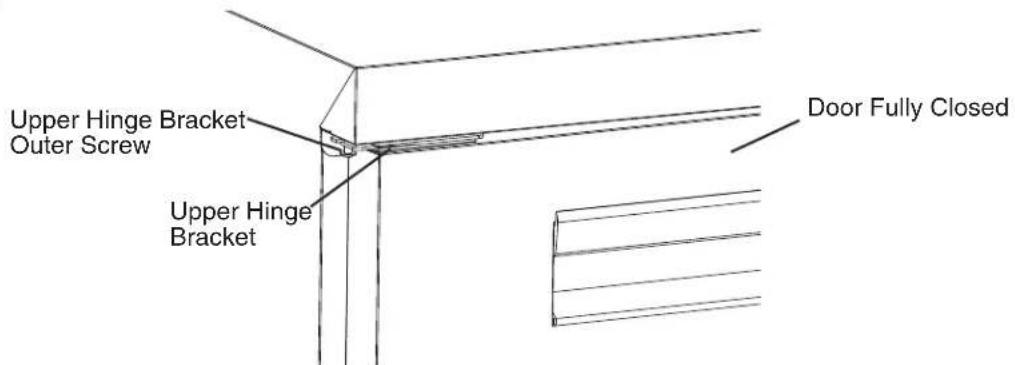
text_image
Upper Hinge Bracket Outer Screw Upper Hinge Bracket Door Fully ClosedFig. 22
17) Check the door operation to assure it opens and closes properly. Note: Hold door at 45^ angle from closed position and release. Door should close on its own. If not, adjust hinge bracket.
18) Unlock the casters and move the appliance back into its original position. Lock the casters once in position, then plug the appliance back into the electrical outlet. Allow the appliance to cool down prior to putting product back in.
E. Door/Drawer Location Reversal
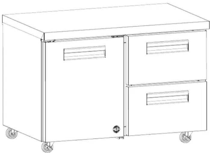
The appliance is provided with a cabinet design which, after being delivered to the installation location, permits changing of the drawer and door locations. To change the drawer and door locations, follow the steps below. Example shows UR48A-D2.
WARNING
- Wear proper PPE (personal protection equipment) when executing these procedures (safety glasses and gloves).
- Keep fingers away from edge of upper hinge bracket. Spring cartridge can cause the upper hinge bracket to move suddenly with extreme force.
Drawer and Drawer Frame Removal
1) Remove all items from the appliance. Make sure the appliance is unplugged from the electrical outlet. Move the appliance out for ease of access then lock the casters. See Fig. 23.
Model Shown: UR48A-D2
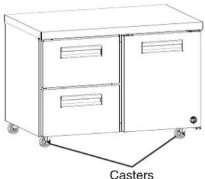
natural_image
Line drawing of a two-door industrial cabinet with wheels and vent slots, labeled 'Casters' at the bottom (no other text or symbols)Fig. 23
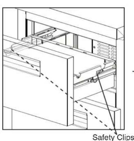
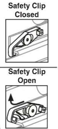
2) Remove the drawers. Pull the drawer out to its fully extended position. Open the safety clips (one on each side) by sliding them forward, then rotating them up. See Fig. 24. Lift up on the handle slightly, then pull to disengage the drawer. Be sure to support the rear and front of the drawer while removing it. WARNING! Be sure to close the safety clips when reinstalling the drawer.
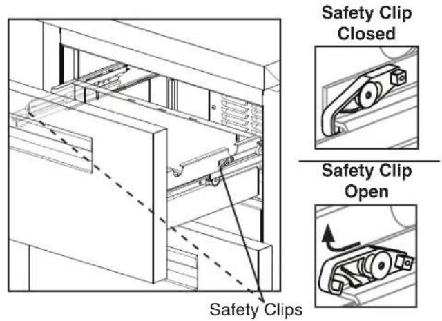
text_image
Safety Clip Closed Safety Clip Open Safety Clips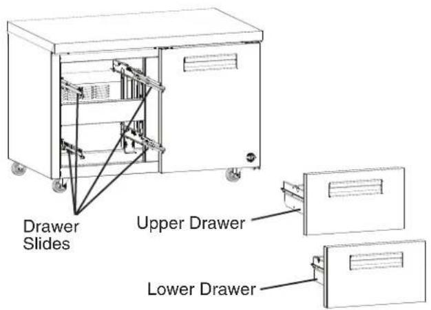
text_image
Drawer Slides Upper Drawer Lower DrawerFig. 24
3) Remove the 4 horizontal mullion screws, then cut the horizontal mullion silicone loose and remove the horizontal mullion. See Fig. 25.
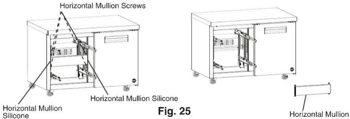
text_image
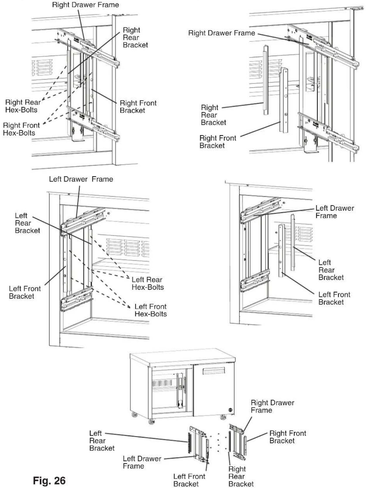
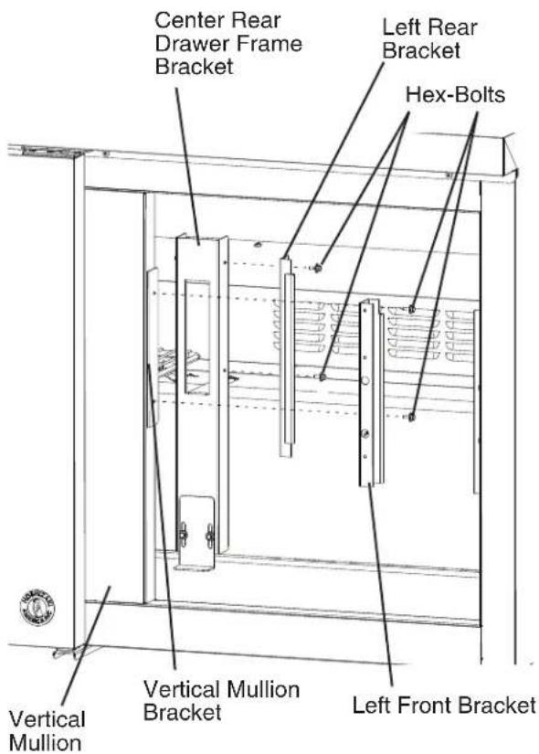
Horizontal Mullion Screws Horizontal Mullion Silicone Horizontal Mullion Silicone Fig. 25 Horizontal Mullion4) Remove the hex-bolts from the 2 right (front and rear) and 2 left (front and rear) brackets (2 hex-bolts per bracket), then remove the right and left drawer frames. See Fig. 26.
Pilaster and Inner Brackets Relocation
5) Remove the shelf from the door section, then remove the pilasters. See Fig. 27.
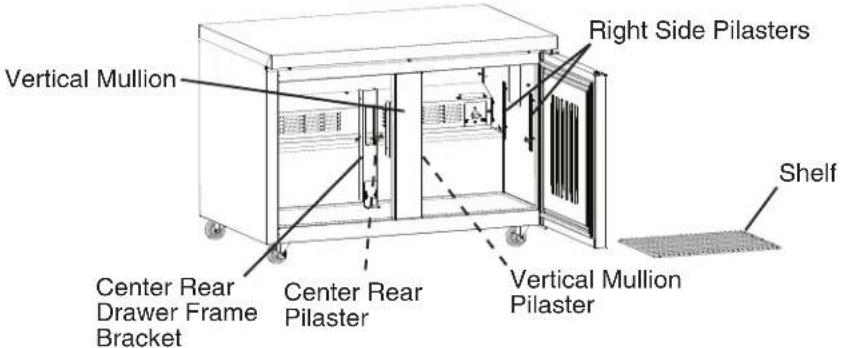
text_image
Vertical Mullion Right Side Pilasters Center Rear Drawer Frame Bracket Center Rear Pilaster Vertical Mullion Pilaster ShelfFig. 27
6) Remove the center rear drawer frame bracket and the filler screw. See Fig. 28. Slide the center rear drawer frame bracket over to the new location and secure it. Place the filler screw in the former center rear drawer frame bracket hole.
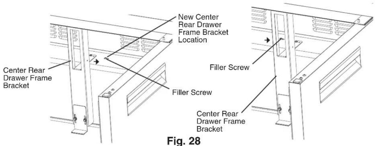
text_image
New Center Rear Drawer Frame Bracket Location Center Rear Drawer Frame Bracket Filler Screw Filler Screw Center Rear Drawer Frame Bracket Fig. 287) Remove the vertical mullion bracket. Rotate 180 degrees and mount it in the vertical mullion right mounting holes. See Fig. 29.
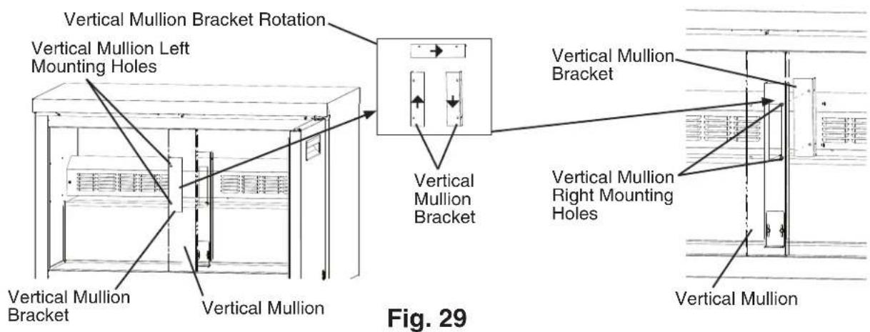
text_image
Vertical Mullion Bracket Rotation Vertical Mullion Left Mounting Holes Vertical Mullion Bracket Vertical Mullion Bracket Vertical Mullion Bracket Vertical Mullion Right Mounting Holes Vertical Mullion Fig. 298) Place and secure the pilasters and shelf support clips in their new location. See Fig. 30. Replace the shelf.
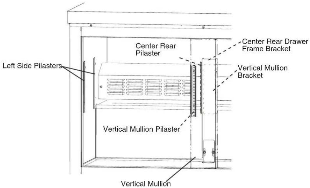
text_image
Left Side Pilasters Center Rear Pilaster Center Rear Drawer Frame Bracket Vertical Mullion Bracket Vertical Mullion Pilaster Vertical MullionFig. 30
Door Relocation
9) With the door closed, loosen, but do not remove, the upper hinge bracket outer screw. See Fig. 31. Next, open the door to the fully open position and remove the upper hinge bracket inner screw. See Fig. 32.
10) Slide the upper hinge bracket out from under the outer screw and remove the door. WARNING! Keep away from upper hinge bracket. Upper hinge bracket may spring closed.
11) Replace the upper hinge bracket inner screw in its original position and tighten, then tighten the upper hinge bracket outer screw.
text_image
Upper Hinge Bracket Upper Hinge Bracket Outer Screw Door ClosedFig. 31
text_image
WARNING! Upper hinge bracket may spring closed Upper Hinge Bracket Inner Screw Door Fully OpenFig. 32
12) Remove the lower hinge bracket. See Fig. 33. Be sure to leave the thrust washer in place.
13) Install the lower hinge bracket in its new location. Be sure the lower hinge bracket is pushed all the way in and the thrust washer is in its original position.
text_image
Thrust Washer Lower Hinge Bracket Mounting Holes Lower Hinge Bracket Bolts Fig. 33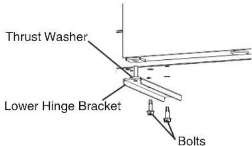
text_image
Thrust Washer Lower Hinge Bracket BoltsFig. 33
14) Remove the black plastic filler cap located from the hole above where the spring cartridge screw will line up. Note: The black plastic filler cap is not reusable.
15) Remove the upper hinge bracket screws from the new location and apply Loctite Threadlocker Blue 242 or 243 to the threads. Next, start the upper hinge bracket outer screw into the appliance. Rotate a few threads into the appliance; do not tighten the screw. See Fig. 34.
text_image
Upper Hinge Bracket Outer Screw Black Plastic Filler Cap Upper Hinge Bracket Inner Screw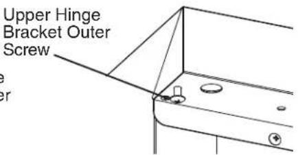
text_image
Upper Hinge Bracket Outer ScrewFig. 34
16) Be sure the lower hinge bracket thrust washer is in place, then place the door on the lower hinge bracket in the fully open position. Slide the door upper hinge bracket outer slot onto the upper hinge bracket outer screw. See Fig. 35.
17) Install the upper hinge bracket inner screw and tighten.
text_image
Upper Hinge Bracket Upper Hinge Bracket Outer Screw Thrust Washer Lower Hinge Bracket Warning! Upper hinge bracket may spring closed Upper Hinge Bracket Upper Hinge Bracket Inner Screw Door Fully Open Door Fully Open Upper Hinge Bracket Outer ScrewFig. 35
18) Close the door and tighten the upper hinge bracket outer screw. See Fig. 36.
text_image
Door Fully Closed Upper Hinge Bracket Upper Hinge Bracket Outer ScrewFig. 36
19) Check the door operation to assure it opens and closes properly. Note: Hold door at 45^ angle from closed position and release. Door should close on its own. If not, adjust hinge bracket.
Drawer Relocation
Left Drawer Frame Relocation
20) Place the left rear bracket in place on the center rear drawer frame bracket with hex-bolts removed in step 4. Leave loose, do not tighten at this time. See Fig. 36.
21) Place the left front bracket in place on the vertical mullion bracket with the hex-bolts removed in step 4. See Fig. 37. Leave loose, do not tighten at this time.
text_image
Center Rear Drawer Frame Bracket Left Rear Bracket Hex-Bolts Vertical Mullion Vertical Mullion Bracket Left Front Bracket
text_image
Center Rear Drawer Frame Bracket Left Rear Bracket Vertical Mullion Vertical Mullion Bracket Left Front BracketFig. 37
22) Place the left drawer frame in the appliance and align under the left rear bracket and tighten, then align under the left front bracket and tighten. See Fig. 38.
Note: Be sure the left drawer frame is under both the left rear bracket lip and left front bracket lip.
text_image
Left Drawer Frame Left Rear Bracket Lip Left Front Bracket Lip Fig. 38Right Drawer Frame Relocation
23) Place the right rear bracket in place on the right side panel with the hex-bolts removed in step 4. Leave loose, do not tighten at this time. See Fig. 39.
24) Place the right front bracket in place on the right side panel with the hex-bolts removed in step 4. Leave loose, do not tighten at this time. See Fig. 39.
text_image
Hex-Bolts Right Rear Bracket Right Front Bracket Vertical Mullion
text_image
Right Rear Bracket Right Front Bracket Vertical MullionFig. 39
25) Place the right drawer frame in the appliance and align under the right rear bracket and tighten, then align under the right front bracket and tighten. See Fig. 40.
Note: Be sure the right drawer frame is under both the right rear bracket lip and right front bracket lip.
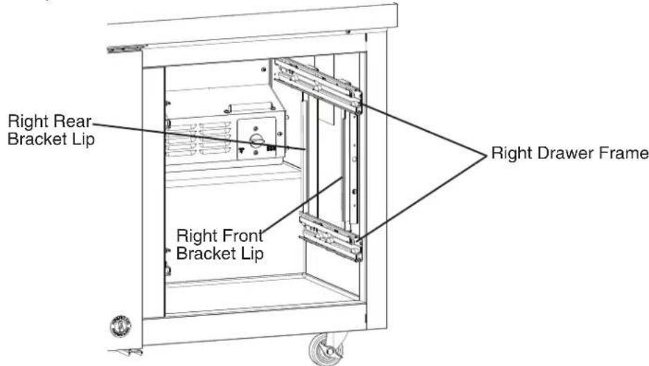
text_image
Right Rear Bracket Lip Right Front Bracket Lip Right Drawer FrameFig. 40
Horizontal Mullion Replacement
26) Place the horizontal mullion in its correct position and secure with screws removed in step 3.
27) Place a bead of food grade silicone down the 2 outside vertical gaps between the mullion and appliance. See Fig. 41.
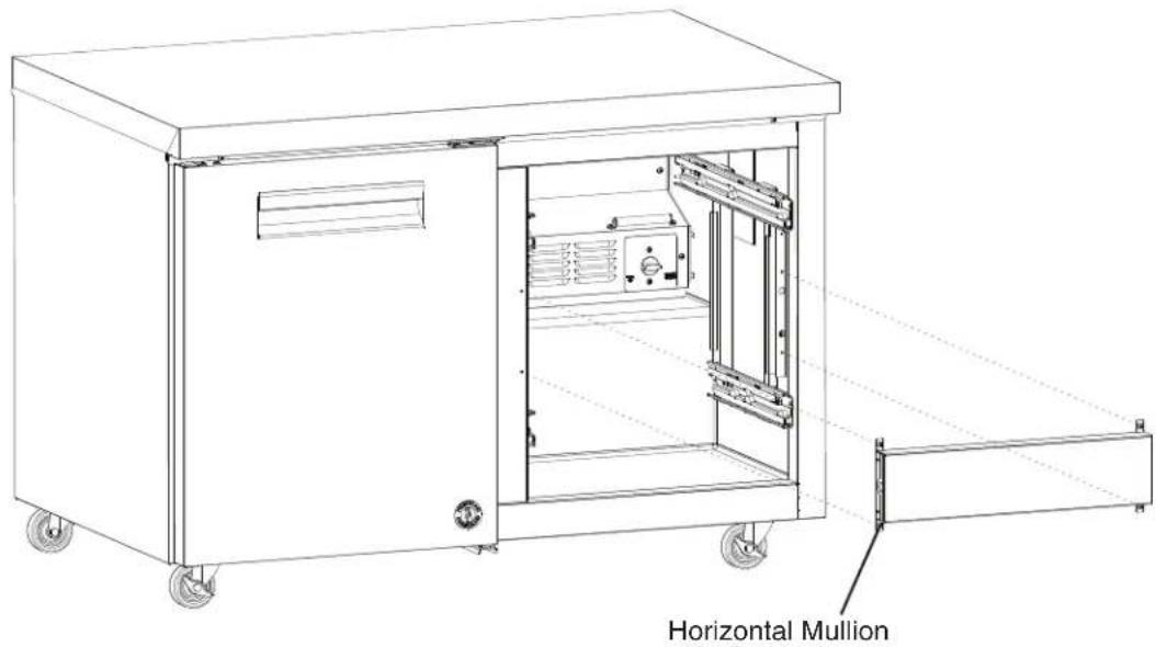
text_image
Horizontal Mullion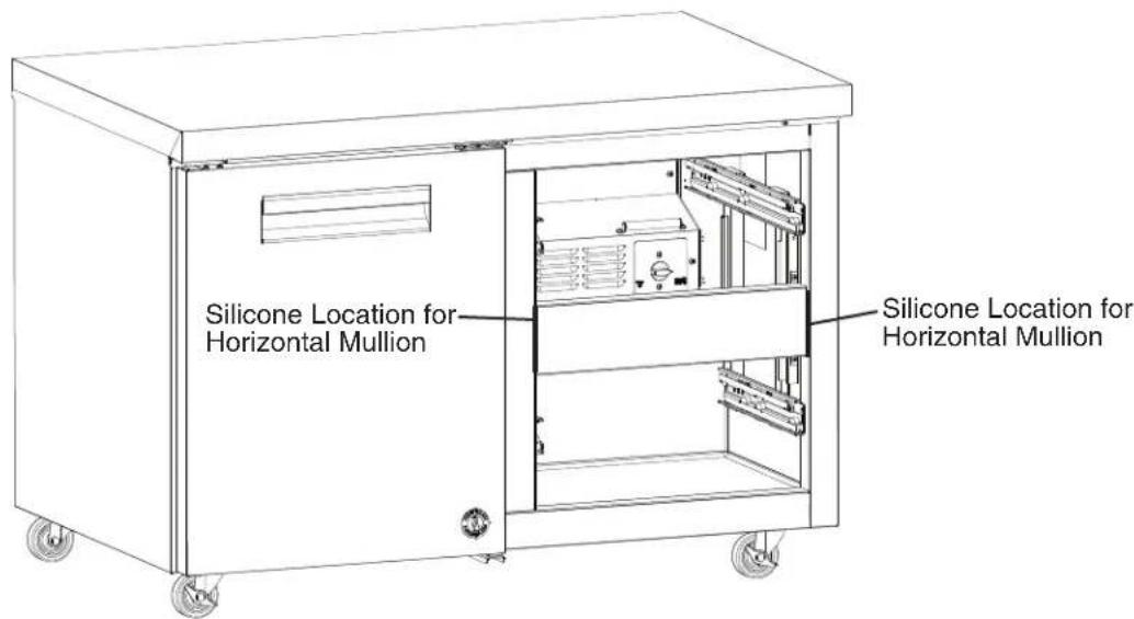
text_image
Silicone Location for Horizontal Mullion Silicone Location for Horizontal MullionModel Shown: UR48A-D2
Fig. 41
28) Place the lower drawer in the lower drawer slides and the upper drawer in the upper drawer slides. See Fig. 42. WARNING! Be sure to close the safety clips when reinstalling the drawer.
29) Make sure all gaskets are making good contact. Using a flashlight, check that there are no openings around all gaskets.
30) Unlock the casters and move the appliance back into its original position. Lock the casters once in position, then plug the appliance back into the electrical outlet. Allow the appliance to cool down prior to loading it with food products.
natural_image
Line drawing of a two-door industrial cabinet with wheels and vent slots (no text or symbols)Model Shown: UR48A-D2
Fig. 42
F. Glass Door Reversal
This appliance is provided with a cabinet design which, after being delivered to the installation location, permits changing of the door swing from left to right or right to left. To change the door swing, an HS kit from your local Hoshizaki distributor is required. See the table below. NOTICE! Improper installation of the HS kit may result in the doors not closing completely and/or the gaskets not sealing correctly. For further details, contact your local Hoshizaki distributor or Hoshizaki Technical Support at 1-800-233-1940.
| Door Type Convert HS Kit Number | ||
| GlassDoor | Right Hinge to Left Hinge | HS-5258 |
| Left Hinge to Right Hinge | HS-5259 | |
G. Electrical Connection
WARNING
- Electrical connection must meet national, state, and local electrical code requirements. Failure to meet these code requirements could result in death, electric shock, serious injury, fire, or severe damage to equipment.
- The appliance requires an independent power supply of proper capacity. See the nameplate for electrical specifications. Failure to use an independent power supply of proper capacity can result in a tripped breaker, blown fuse, damage to existing wiring, or component failure. This could lead to heat generation or fire.
- THE APPLIANCE MUST BE GROUNDED. The appliance is equipped with a NEMA 5-15 three-prong grounding plug [••] to reduce the risk of potential shock hazards. It must be plugged into a properly grounded, independent 3-prong wall outlet. If the outlet is a 2-prong outlet, it is your personal responsibility to have a qualified electrician replace it with a properly grounded, independent 3-prong wall outlet. Do not remove the ground prong from the power cord and do not use an adapter plug. Failure to follow these instructions may result in death, electric shock, or fire.
- To reduce the risk of electric shock, do not touch the plug with damp hands.
- Do not use an extension cord.
- Do not use an appliance with a damaged power cord. The power cord should not be altered, jerked, bundled, weighed down, pinched, or tangled. Such actions could result in electric shock or fire. To unplug the appliance, be sure to pull the plug, not the cord, and do not jerk the cord.
- The GREEN ground wire in the factory-installed power cord is connected to the appliance. If it becomes necessary to remove or replace the power cord, be sure to connect the power cord's ground wire.
• Usually an electrical permit and services of a licensed electrician are required.
- The maximum allowable voltage variation is ± 10 percent of the nameplate rating.
H. Final Checklist
1) Is the appliance level?
2) Have the casters been properly installed and have the front casters been locked?
3) Is the appliance in a site where the ambient temperature is constantly within 45^ F to 100^ F ( 7^ C to 38^ C)?
4) Have the shipping carton, tape, and packing material been removed from the appliance? Has the protective plastic film been removed from both the exterior panels and the interior door/drawer panel?
5) Have the appliance and accessories been checked for shipping damage?
6) Are the factory-installed rear bumpers in place to ensure proper rear clearance? For undercounter and worktop models, is there at least 1.5" (4 cm) overhead clearance for proper ventilation? For prep table models, is there at least 10" (25 cm) clearance above the rail hood to allow the rail cover to open?
7) For prep table models, have the rail dividers, pans, rail cover, cutting board brackets, and cutting board been properly installed?
8) Has the power supply voltage been checked or tested against the nameplate rating? Is the power supply a properly grounded, independent wall outlet? Does the electrical connection meet all national, state, and local code and regulation requirements?
9) Have the refrigerant lines been checked to make sure they do not rub or touch other lines or surfaces? Has the condenser fan blade been checked to make sure it turns freely? Is the compressor securely attached?
10) Have the shelves been adjusted to the desired height?
11) Has the end user been given the instruction manual, and instructed on how to operate the appliance and the importance of the recommended periodic maintenance?
12) Has the end user been given the contact information of an authorized service agent?
13) Has the warranty card been filled out and forwarded to the factory for warranty registration?
II. Operating Instructions
A. Important Notes About Usage
DANGER
Risk of Fire or Explosion
Flammable Refrigerant Used
- Do not use mechanical devices to defrost.
- Do not puncture refrigerant tubing. Risk of fire or explosion due to puncture of refrigerant tubing; follow handling instructions carefully.
- Do not place any potential ignition sources in or near the appliance.
- Only qualified service technicians should install and service the appliance.
- Wear appropriate personal protective equipment (PPE) when servicing the appliance.
- Failure to install, operate, and maintain the appliance in accordance with this manual may adversely affect safety, performance, component life, and warranty coverage.
- To reduce the risk of electric shock, do not touch the plug with damp hands.
-
Do not splash, pour, or spray water directly onto or into the appliance. This might cause short circuit, electric shock, corrosion, or failure.
-
The appliance is not intended for use by persons (including children) with reduced physical, sensory, or mental capabilities, or lack of experience and knowledge, unless they have been given supervision or instruction concerning use of the appliance by a person responsible for their safety.
• Children should be properly supervised around the appliance. - Do not climb, stand, or hang on the appliance or doors/drawers or allow children or animals to do so. Do not climb into the appliance or allow children or animals to do so. Death or serious injury could occur or the appliance could be damaged.
- Be careful not to pinch fingers when opening and closing the doors/drawers or rail cover (prep table models) or when handling food pans. Be careful when opening and closing the doors/drawers or rail cover when children are in the area.
- Open and close the doors/drawers and rail cover (prep table models) with care. Opening the doors/drawers or rail cover too quickly or forcefully may cause injury or damage to the appliance or surrounding equipment.
- Do not use combustible spray or place volatile or flammable substances in or near the appliance. They might catch fire.
- Keep the area around the appliance clean Dirt, dust, or insects in the appliance could cause harm to individuals or damage to the equipment.
- Do not throw anything onto the shelves or load any single shelf with more than 120 lb. (54.5 kg) of product. They might fall off and cause injury.
- Do not load any single drawer with more than 75 lb. (34 kg) of product. Depending on the weight of product in the drawers, secure the unit as necessary to prevent it from overturning. Do not open more than one drawer at a time.
⚠ WARNING, continued
- The appliance is designed only for temporary storage of food. Employ sanitary methods. Use for any other purposes (for example, storage of chemicals or medical supplies such as vaccine and serum) could cause deterioration of stored items.
- Do not block air inlets or outlets, otherwise cooling performance may be reduced.
- Do not tightly pack the cabinet. Allow some space between items to ensure good air flow. Also allow space between items and interior surfaces.
- Do not put warm or hot foods in the cabinet. Let them cool first, or they will raise the cabinet temperature and could deteriorate other foods in the cabinet or overload the appliance.
- Food storage and handling must comply with applicable codes and regulations.
- All foods should be wrapped in plastic film or stored in sealed containers. Otherwise foods may dry up, pass their smells onto other foods, cause frost to develop, result in poor appliance performance, or increase the likelihood of cross-contamination. Certain dressings and food ingredients, if not stored in sealed containers, may accelerate corrosion of the evaporator, resulting in failure.
- Do not store items near air outlets. Otherwise, items may freeze up and crack or break causing a risk of injury or contamination of other food.
Additional Warnings for Prep Table Models
- The entire rail must always be covered by rail dividers and pans (1/6 size, up to 6" (15 cm) deep). Otherwise, the appliance will not cool properly.
- Use only 1/6 size pans up to 6" (15 cm) deep. Do not use damaged pans.
- Ingredients must be pre-chilled to 37^ (3^) or less before placing in rail.
- Keep the rail cover closed when not actively preparing food.
- The rail is for keeping ingredients cool while preparing food. If not actively preparing food for a long period such as overnight, seal pans with plastic wrap in addition to closing the rail cover. Depending on conditions, the cabinet temperature setting may need to be adjusted to prevent items from freezing. Alternatively, seal ingredients and store them in a refrigerator or freezer.
NOTICE
- Protect the floor when moving the appliance to prevent damage to the floor.
- Keep ventilation openings, in the appliance enclosure or in the built-in structure, clear of obstruction. Do not place anything on top of the appliance in an undercounter installation. There must be at least 1.5" (4 cm) overhead clearance for proper ventilation. The factory-installed rear bumpers must be in place to ensure proper rear clearance. Blockage of airflow could negatively affect performance and damage the appliance.
- Do not allow the appliance to bear any outside weight.
- To prevent deformation or cracks, do not spray insecticide onto the plastic parts or let them come into contact with oil.
- To avoid damage to the gasket, use only the door/drawer handle when opening and closing.
- To avoid damage to the top seal, do not lift the appliance by the top panel or remove the top panel.
- Do not leave the doors/drawers open.
Additional Notice for Prep Table Models
- Do not place anything on top of the rail hood or rail cover and do not lift the appliance by the rail hood or rail cover. The rail hood and rail cover are not designed to bear any outside weight.
B. Startup
| ⚠ WARNING |
| All parts are factory-adjusted. Improper adjustments may adversely affect safety, performance, component life, and warranty coverage. |
1) Plug the appliance into the electrical outlet. WARNING! To reduce the risk of electric shock, do not touch the plug with damp hands. At startup, there is a slight delay before the compressor starts.
2) Allow the appliance to cool down prior to loading it with food products. For prep table models, the entire rail must be covered by rail dividers and pans (1/6 size, up to 6" (15 cm) deep) and the rail cover must be closed. Otherwise, the appliance will not cool properly. Leave the pans empty until the appliance cools down. Wash the pans and cutting board before use. WARNING! Make sure the cutting board brackets and cutting board are secure. Otherwise, the cutting board could come off and cause injury.
C. Controls and Adjustments
1. Temperature Reading
A thermometer with both °F and °C scales is mounted in the cabinet. See Fig. 43.
2. Adjusting the Temperature
The appliance features a cabinet temperature control dial. The warmest setting is 1 and the coldest setting is 7. See the table below for default settings.
| Model Default | Temperature Setting Approximate | Default Temperature |
| Undercounter Worktop | Between 4 and 5 Refrigerator: | 34°F (1°C)Freezer: -5°F (-21°C) |
| Prep Table Between 4 and 5 34°F (1°C) | ||
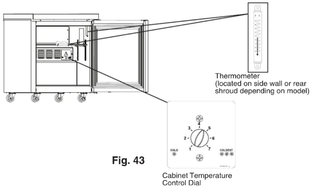
text_image
Thermometer (located on side wall or rear shroud depending on model) Fig. 43 Cabinet Temperature Control DialD. Defrost
DANGER
Risk of Fire or Explosion Flammable Refrigerant Used
- Do not use mechanical devices to defrost.
- Do not puncture refrigerant tubing. Risk of fire or explosion due to puncture of refrigerant tubing; follow handling instructions carefully.
1. Undercounter and Worktop Refrigerators
Off-Cycle Defrost: Undercounter and worktop refrigerators defrost naturally between run cycles.
2. Prep Table Refrigerators and Undercounter and Worktop Freezers
Prep tables and freezers use a heated, time-initiated, temperature-terminated defrost.
-
Prep tables have a defrost interval of 6 hours and freezers have a defrost interval of 8 hours. The defrost timer starts when power is supplied to the appliance.
The minimum defrost time is 5 min.
The maximum defrost time is 45 min. for prep tables and 1 hour for freezers. -
When the defrost thermistor warms to 46^ (7.7°C) on prep tables and 50^ (10°C) on freezers, defrost terminates.
- On prep tables, the compressor energizes 1-min. after defrost heater de-energizes (drip time) and the evaporator fan motor(s) energize 30-sec. after the compressor energizes. Note that the 30-sec. evaporator fan motor delay time is a maximum; if the defrost thermistor cools to 40^ (4.4°C) before the 30-sec. evaporator fan motor delay timer terminates, the evaporator fan motor(s) will energize.
- On freezers, the compressor energizes 3-min. after defrost heater de-energizes (drip time) and the evaporator fan motor(s) energize 4-min. after the compressor energizes. Note that the 5-min. evaporator fan motor delay time is a maximum; if the defrost thermistor cools to 25^ (-3.8°C) before the 5-min. evaporator fan motor delay timer terminates, the evaporator fan motor(s) will energize.
To manually initiate or terminate a defrost cycle: Turn the cabinet temperature control dial to 7, pause for 3 to 10 sec., then return the cabinet temperature control dial to any position below 7. Defrost initiates or terminates within 5 sec.
Note: When defrost is manually initiated it continues through the normal defrost cycle unless manually terminated.
E. Food Storage
WARNING
- Storage of foods should follow all local codes and regulations.
- The appliance is designed only for temporary storage of food. Employ sanitary methods. Use for any other purposes (for example, storage of chemicals or medical supplies such as vaccine and serum) could cause deterioration of stored items.
- Do not block air inlets or outlets, otherwise cooling performance may be reduced.
- Do not tightly pack the cabinet. Allow some space between items to ensure good air flow. Also allow space between items and interior surfaces.
- Do not put warm or hot foods in the cabinet. Let them cool first, or they will raise the cabinet temperature and could deteriorate other foods in the cabinet or overload the appliance.
- All foods should be wrapped in plastic film or stored in sealed containers. Otherwise foods may dry up, pass their smells onto other foods, cause frost to develop, result in poor appliance performance, or increase the likelihood of cross-contamination. Certain dressings and food ingredients, if not stored in sealed containers, may accelerate corrosion of the evaporator, resulting in failure.
- Do not store items near air outlets. Otherwise, items may freeze up and crack or break causing a risk of injury or contamination of other food.
Additional Information for Prep Table Models
- The entire rail must always be covered by rail dividers and pans (1/6 size, up to 6" (15 cm) deep). Otherwise, the appliance will not cool properly.
- Use only 1/6 size pans up to 6" (15 cm) deep. Do not use damaged pans.
- Ingredients must be pre-chilled to 37^ (3°C) or less before placing in rail.
- Keep the rail cover closed when not actively preparing food.
- The rail is for keeping ingredients cool while preparing food. If not actively preparing food for a long period such as overnight, seal pans with plastic wrap in addition to closing the rail cover. Depending on conditions, the cabinet temperature setting may need to be adjusted to prevent items from freezing. Alternatively, seal ingredients and store them in a refrigerator or freezer.
F. Safety Devices
1. Compressor External or Internal Protector
If combined temperature/amperage value is above the limit specified by the compressor manufacturer, the compressor protector operates independently to turn off the compressor. The compressor protector de-energizes the compressor until the temperature/amperage value returns to an acceptable level.
2. Short-Cycle Protection
There is a 2-minute minimum off-time and on-time for the compressor.
Note: Time may vary with compressor overload or high-pressure switch activation.
3. High-Pressure Switch (If Applicable)
If pressure on the high-side of the unit exceeds Hoshizaki specifications, the high-pressure switch activates and interrupts the compressor circuit, de-energizing the compressor until the pressure returns to an acceptable level.
G. Cooling Performance
Be sure the appliance is properly installed and located for optimum cooling performance. If cooling performance is not at its optimum level, check the following items:
- Doors/drawers opened too often.
- Doors/drawers left open. Close.
- Cabinet too tightly packed or air inlets/outlets blocked. Allow some space between items to ensure good air flow.
- Warm or hot foods inside. Take them out until they cool down more.
- Ambient temperature too high. Avoid installation near high heat producing equipment or exposure to direct sunlight.
- Temperature control setting not cold enough. Adjust to a colder setting. The warmest setting is 1 and the coldest setting is 7.
- Prep Table Refrigerators and Undercounter and Worktop Freezers: Appliance in defrost cycle. The cabinet temperature may rise temporarily during the defrost cycle, but this will not affect the food inside.
Additional Information for Prep Table Models
- Pans and rail dividers not in place. The entire rail must always be covered by rail dividers and pans (1/6 size, up to 6" (15 cm) deep) or the rail will not cool properly.
- Warm or hot ingredients inside. Only load ingredients that have been pre-chilled to 37^ (3^) or less.
- Rail cover open when not actively preparing food. When not actively preparing food, close the rail cover.
H. Cabinet Condensation
In the event condensation develops on the cabinet exterior, check the following items:
- Doors/drawers left open. Close.
- Ambient humidity too high. In high humidity areas it may be necessary to wipe off the cabinet frame occasionally.
III. Cleaning and Maintenance Instructions
A. Cleaning
WARNING
- Unplug the appliance before cleaning to prevent electric shock by unexpected entrance of water into the appliance or injury by moving parts. To reduce the risk of electric shock, do not touch the plug with damp hands.
- Before cleaning the appliance, move all foods into another clean refrigerator or freezer.
- Do not splash, pour, or spray water directly onto or into the appliance. This might cause short circuit, electric shock, corrosion, or failure.
- Carefully follow instructions provided with cleaning and sanitizing products.
NOTICE
- To prevent damage to the plastic surfaces, do not use the following: hot water, thinner, benzine, alcohol, petroleum, soap powder, polishing powder, alkaline cleaner, acid, scouring pad and especially those strong cleaners for use on a ventilating fan or a cooking range.
- To prevent corrosion and damage to stainless steel surfaces, use only products formulated for use on stainless steel appliances. Do not use steel wool, abrasive products, or products containing sodium hypochlorite (chlorine bleach).
- Use a clean cloth for cleaning.
1. Exterior
Wipe the exterior occasionally with a clean, soft cloth. Use a damp cloth containing a neutral cleaner to wipe off oil or dirt buildup. Clean any rust colored spots using a non-abrasive cleanser.
2. Cabinet Interior
Spills should be wiped up promptly to avoid unpleasant odors. The cabinet interior should be cleaned periodically with a mild soap or detergent and warm water.
3. Door/Drawer Gaskets
Door/drawer gaskets should be cleaned regularly with mild soap and warm water to remove dirt and grease.
4. Shelves
Remove and clean regularly.
5. Glass Door
Wipe occasionally with a clean, soft cloth. Use a damp cloth containing a neutral cleaner to wipe off oil or dirt buildup.
6. Drawers
Drawers and drawer slides are removable.
- To remove a drawer: Remove all items from the drawer. Pull the drawer out to its fully extended position. Open the safety clips (one on each side) by sliding them forward, then rotating them up. See Fig. 44. Lift up on the handle slightly, then pull to disengage the drawer. Be sure to support the rear and front of the drawer while removing it. WARNING! Be sure to close the safety clips when reinstalling the drawer.
- To remove a drawer slide (center slide containing rollers): Push up on the stop lever while pulling on the drawer slide. See Fig. 45. Drawer slides do not require lubrication, but drawer slides should be kept clean and free of food. Note: Drawer slides are dishwasher safe.
text_image
Safety ClipsFig. 44
text_image
Safety Clip Closed Safety Clip Open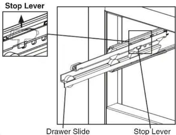
text_image
Stop Lever Drawer Slide Stop LeverFig. 45
7. Worktop (Worktop Models)
Clean the work surface as often as necessary to maintain a clean, sanitary surface. Clean any rust colored spots using a non-abrasive cleanser.
8. Cutting Board (Prep Table Models)
Remove and clean the cutting board as often as necessary to maintain a clean, sanitary work surface. Also clean the space underneath the cutting board as often as necessary to maintain a clean, sanitary surface. After cleaning, slide the cutting board back into the cutting board brackets. WARNING! Make sure the cutting board brackets and cutting board are secure. Otherwise, the cutting board could come off and cause injury.
9. Rail, Rail Hood, and Rail Cover (Prep Table Models)
Spills and splashes should be wiped up promptly to avoid unpleasant odors. Wipe the rail area, the rail hood, and the rail cover occasionally with a clean, damp sponge or cloth containing a neutral cleaner. Clean any rust colored spots using a non-abrasive cleanser. Do not pour or spray water into the rail area.
WARNING!
- Support the rail cover when cleaning. Otherwise, the rail cover could close suddenly and cause injury.
- Metal edges can cause cuts. Use care and wear protective gloves when cleaning. NOTICE! Do not allow any foreign objects to fall into the cabinet while cleaning.
10. Spill Guard
Remove the pans and wipe the spill guard occasionally with a clean, damp sponge or cloth containing a neutral cleaner. Clean any rust colored spots using a non-abrasive cleanser. Do not pour or spray water into the rail area.
B. Maintenance
WARNING
- Unplug the appliance before performing maintenance to prevent electric shock or injury by moving parts. To reduce the risk of electric shock, do not touch the plug with damp hands.
- Before performing maintenance, move all foods into another clean refrigerator or freezer.
1. Condenser
Check the condenser once a year and use a brush or vacuum cleaner to clean the condenser as required. More frequent cleaning may be required depending on conditions.
2. Power Supply Connection
If the plug or power cord is damaged, contact your local Hoshizaki service representative or local Hoshizaki distributor immediately and ask for repairs.
All other maintenance or service on the appliance should be performed in accordance with the Hoshizaki Service Manual by a qualified service technician.
IV. Preparing the Appliance for Periods of Non-Use
When shutting down the appliance for more than one week, follow the instructions below.
| ⚠ WARNING |
| When preparing the appliance for long storage, prevent the doors/drawers from closing to reduce the risk of children getting trapped. |
| NOTICE |
| When preparing the appliance for long storage, clean the appliance. See "III.A. Cleaning" for details. |
1) Before shutting down the appliance, move all foods into another clean refrigerator or freezer.
2) Unplug the appliance. WARNING! To reduce the risk of electric shock, do not touch the plug with damp hands.
V. Disposal
DANGER
Risk of Fire or Explosion Flammable Refrigerant Used
- Follow handling instructions carefully in compliance with U.S. government regulations.
- Do not puncture refrigerant tubing. Risk of fire or explosion due to puncture of refrigerant tubing; follow handling instructions carefully.
- Dispose of properly in accordance with federal or local regulations.
When preparing the appliance for disposal, remove the doors/drawers to reduce the risk of children getting trapped. Leave any shelves in place so that children may not easily climb inside.
The appliance contains refrigerant and must be disposed of in accordance with applicable national, state, and local codes and regulations. Refrigerant must be recovered by properly certified service personnel.