EFAB-II - Hi-Fi System SANUS - Free user manual and instructions
Find the device manual for free EFAB-II SANUS in PDF.

User questions about EFAB-II SANUS
0 question about this device. Answer the ones you know or ask your own.
Ask a new question about this device
Download the instructions for your Hi-Fi System in PDF format for free! Find your manual EFAB-II - SANUS and take your electronic device back in hand. On this page are published all the documents necessary for the use of your device. EFAB-II by SANUS.
USER MANUAL EFAB-II SANUS
Assembly Instructions for Model: EFAB-II
Thank you for choosing the Sanus Systems Model EFAB-II. Every effort has been made to ensure that your Sanus Systems furniture is perfect. If you have questions or feel that there is a problem of any kind, please contact us 800-359-5520 or at www.sanus.com. We can quickly help with any issues regarding assembly or missing parts. Replacement parts for Sanus systems products purchased through authorized dealers will be shipped directly to you.
natural_image
Technical line drawing of a rectangular electronic device with mounting holes and a curved base (no text or symbols)Supplied Parts List: (All threaded fasteners are shown full size.)

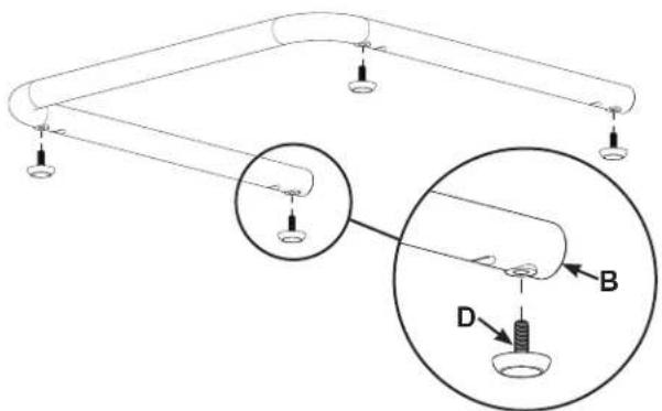
Step 1 - Attach Carpet Spikes or Floor Glides.
CAUTION: the ends of the Carpet Spikes are very sharp and may scratch non-carpeted flooring, or they may be hazardous to small children. For these reasons Sanus includes Floor Glides.
If the Floor Glides (D) are used, do not install the Carpet Spikes (E), simply thread the Floor Glides into the threaded holes in the Metal Base (B) instead of the Carpet Spikes as shown in Diagram 1A.
Thread a Spike Nut (F) onto each Carpet Spike (E); then, thread the Carpet Spikes into the Metal Base (B) as shown in Diagram 1B.
Stand the Metal Base (B) upright and screw the Carpet Spikes (E) in or out until the Metal Base is level; then, turn the Spike Nuts (F) until they are snug against the Metal Base to lock the Carpet Spikes in place. If the Floor Glides (D) are used, simply thread them in or out until the Metal Base (D) is level.
Diagram 1A
text_image
Diagram of a mechanical or electrical setup with labeled components A, B, and D, showing connections and a magnified inset.Diagram 1B

text_image
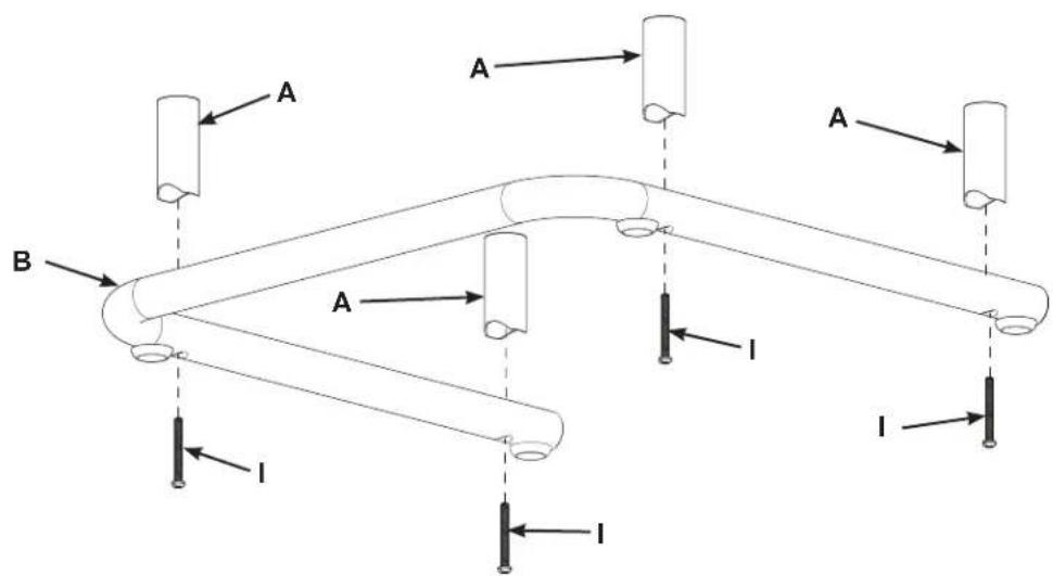
Diagram showing a mechanical or electrical component with labeled parts F, B, and E, including a magnified inset highlighting component E.Step 2 - Attach 3" Cope Tubes to Metal Base
Place a Pan Head Bolt (I) through each of the four holes in the Metal Base (B); then, thread them into the four 3" Cope Tubes (A).
Tighten the four Pan Head Bolts (I).
Diagram 2
text_image
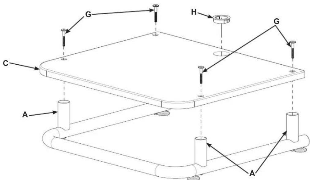
A A A B A I I IStep 3 - Place Audio Shelf on 3" Cope Tubes
Place the Audio Shelf (C) onto the 3" Cope Tubes (A).
NOTE:
If you are installing additional Audio Shelves, refer to the Assembly Instructions for Model: EFAS-II.
Secure the Audio Shelf (C) to the 3" Cope Tubes (A) using the Top Bolts (G). Use the Allen Key (J) to tighten the Top Bolts.
Press the Wire Bushing (H) into the hole in the Audio Shelf (C).
Diagram 3