Medium Fusion MSM3095 - TV Stand Chief - Free user manual and instructions
Find the device manual for free Medium Fusion MSM3095 Chief in PDF.

User questions about Medium Fusion MSM3095 Chief
0 question about this device. Answer the ones you know or ask your own.
Ask a new question about this device
Download the instructions for your TV Stand in PDF format for free! Find your manual Medium Fusion MSM3095 - Chief and take your electronic device back in hand. On this page are published all the documents necessary for the use of your device. Medium Fusion MSM3095 by Chief.
USER MANUAL Medium Fusion MSM3095 Chief
INSTALLATION INSTRUCTIONS
natural_image
Technical line drawing of a mechanical assembly with labeled MSM (no text or symbols on the diagram itself)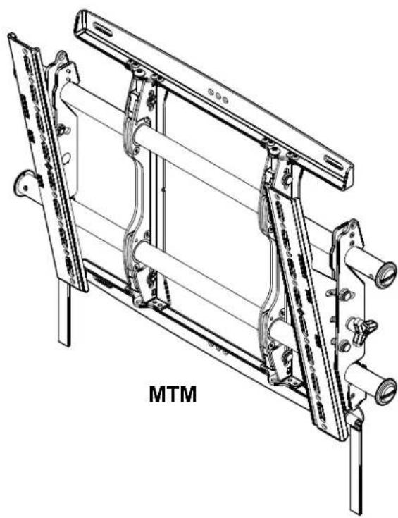
natural_image
Technical line drawing of a mechanical assembly with labeled MTM (no text or symbols on the diagram itself)FUSION MEDIUM HEIGHT ADJUST FLAT PANEL MOUNTS
- Go to http://downloads.chiefmfg.com/MANUALS-I/MSM_MTMSeries-I.pdf for translated instructions.
• Переведенные инструкции находятся по адресу http://downloads.chiefmfg.com/MANUALS-I/MSM_MTMSeries-l.pdf
DISCLAIMER
Milestone AV Technologies, and its affiliated corporations and subsidiaries (collectively "Milestone"), intend to make this manual accurate and complete. However, Milestone makes no claim that the information contained herein covers all details, conditions or variations, nor does it provide for every possible contingency in connection with the installation or use of this product. The information contained in this document is subject to change without notice or obligation of any kind. Milestone makes no representation of warranty, expressed or implied, regarding the information contained herein. Milestone assumes no responsibility for accuracy, completeness or sufficiency of the information contained in this document.
Chief® is a registered trademark of Milestone AV Technologies. All rights reserved.

IMPORTANT SAFETY INSTRUCTIONS

WARNING: A WARNING alerts you to the possibility of serious injury or death if you do not follow the instructions.

CAUTION: A CAUTION alerts you to the possibility of damage or destruction of equipment if you do not follow the corresponding instructions.

WARNING: Failure to read, thoroughly understand, and follow all instructions can result in serious personal injury, damage to equipment, or voiding of factory warranty! It is the installer's responsibility to make sure all components are properly assembled and installed using the instructions provided.

WARNING: Failure to provide adequate structural strength for this component can result in serious personal injury or damage to equipment! It is the installer's responsibility to make sure the structure to which this component is attached can support five times the combined weight of all equipment. Reinforce the structure as required before installing the component.

WARNING: Exceeding the weight capacity can result in serious personal injury or damage to equipment! It is the installer's responsibility to make sure the combined weight of all components located on the MSM/MTM does not exceed 125 lbs (56.7 kg) for dual wood stud or concrete attachment, and 75 lbs (34.0 kg) for single wood stud attachment.

WARNING: Use this mounting system only for its intended use as described in these instructions. Do not use attachments not recommended by the manufacturer.

WARNING: Never operate this mounting system if it is damaged. Return the mounting system to a service center for examination and repair.

WARNING: Do not use this product outdoors.
IMPORTANT ! : The MSM/MTM mounts are designed to be mounted to an 8" concrete, 8"x8"x16" concrete block or 2" x 4" wood studs (16" on center) wall covered by drywall of 5/8" maximum thickness.
--SAVE THESE INSTRUCTIONS--
DIMENSIONS
![16.00 [406.4] 8.00 [203.2] 1.00 [25.4] [ ] 11.13 [82.6] 1.75 [4.5] 15.10 [83.4] RAILS CAN BE SLID LEFT OR RIGHT FOR OFFSET 18.79 [477.4] 25.57 [49.5]](/content/2026/06/1203821/images/e900d0479b3f213d56618cede28c955436708fd9978934285bbeeb746807fad4.jpg)
MSM
NOTES:
- MAX MOUNTING PATTERN IS 22.9"[581.6mm] WITHOUT REVERSING UPRIGHTS MAX MOUNTING PATTERN IS 25.6"[650.2mm] WITH REVERSING UPRIGHTS,2. FOR RECESSED APPLICATIONS, MINIMUM VERTICAL LIFT FOR HOOK 3. ENGAGEMENT IS .56"[14.2mm],
- MOUNT IS 1.96"[49.8mm] DEEP.
![1.96[49.8] 7 16.7B [26.1] 16.53 [419.9]](/content/2026/06/1203821/images/06cce4bc11cba6875c5278877508395c8500b8fe8356c35a94ffeb547d34ea65.jpg)
![.38 [9.6] 7.87 [200] 6.40 [162.5] 5.91 [150] 4.43 [112.5] 3.94 [100] 2.46 [62.5] 1.97 [50] .49 [12.5] 0 .49 [12.5] 1.97 [50] 2.46 [62.5] 3.94 [100] 4.43 [112.5] 5.91 [50] 6.40 [162.5] 7.87 [200] .98 [25]](/content/2026/06/1203821/images/913684f0776aca28b9ffa845035f3fbc85a5596286d6cd4daf0c3a9356cc6464.jpg)
DIMENSIONS: [MILLIMETERS] INCHES
![16.00 [106.4] 8.00 [203.2] 1.00 [5.4] .50 [2.7] φ .33 [8.3] 2.00 [50.8] 11.13 [82.6] 1.75 [4.5] 15.10 [83.4] 1.00 [5.4] 18.79 [77.4] 25.57 [49.5]](/content/2026/06/1203821/images/162d2153e3af93d10bcee29e95781bd3664008dcb62abf80e9796f31f89c81ce.jpg)
MTM
NOTES:
- MAX MOUNTING PATTERN IS 21.6"[548.6mm] WITHOUT REVERSING UPRIGHTS. MAX MOUNTING PATTERN IS 26.2"[665.5mm] WITH REVERSING UPRIGHTS.2. FOR RECESSED APPLICATIONS, MINIMUM VERTICAL LIFT FOR HOOK 3. ENGAGEMENT IS .42"[10.7mm].
RAILS CAN BE SLID LEFT OR RIGHT FOR OFFSET APPLICATIONS.4. 5. MOUNT IS 1.99"[50.5mm] DEEP WHEN FLAT TO THE WALL,
![12° 4.83 [22.6] 16.53 [419.9]](/content/2026/06/1203821/images/5be65f48991741926cd4f357c55c6ee21d303cd267d2b6900856500a50619257.jpg)
![.38 [9.5] φ .32 [8.1] 7.87 [200] 6.36 [161.5] 5.91 [150] 4.39 [111.5] 3.94 [100] 2.42 [61.5] 1.97 [50] .45 [11.5] 0 .45 [11.5] 1.97 [50] 2.42 [61.5] 3.94 [100] 4.39 [111.5] 5.91 [150] 6.36 [161.5] 7.87 [200] 16.50 [419.1] 1.06 [27]](/content/2026/06/1203821/images/be83a574edb81cd61cee54192300e3e8e1b5331b73f7c2fc53886d9e7d11ce1c.jpg)
DIMENSIONS: [MILLIMETERS] INCHES
LEGEND
 | Tighten Fastener |  | Pencil Mark |
| Apretar elemento de fijación | Marcar con lápiz | ||
| Befestigungsteil festziehen | Stiftmarkierung | ||
| Apertar fixador | Marcar com lápis | ||
| Serrare il fissaggio | Segno a matita | ||
| Bevestiging vastdraaien | Potloodmerkteken | ||
| Serrez les fixations | Marquage au crayon | ||
 | Loosen Fastener |  | Drill Hole |
| Aflojar elemento de fijación | Perforar | ||
| Befestigungsteil lösen | Bohrloch | ||
| Desapertar fixador | Fazer furo | ||
| Allentare il fissaggio | Praticare un foro | ||
| Bevestiging losdraaien | Gat boren | ||
| Desserrez les fixations | Percez un trou | ||
 | Phillips Screwdriver |  | Adjust |
| Destornillador Phillips | Ajustar | ||
| Kreuzschlitzschraubendreher | Einstellen | ||
| Chave de fendas Phillips | Ajustar | ||
| Cacciavite a stella | Regolare | ||
| Kruiskopschroevendraaier | Afstellen | ||
| Tournevis à pointe cruciforme | Ajuster | ||
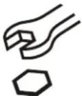 | Open-Ended Wrench |  | Remove |
| Llave de boca | Quitar | ||
| Gabelschlüssel | Entfernen | ||
| Chave de bocas | Remover | ||
| Chiave a punte aperte | Rimuovere | ||
| Steeksleutel | Verwijderen | ||
| Clé à fourche | Retirez | ||
 | By Hand |  | Optional |
| A mano | Opcional | ||
| Von Hand | Optional | ||
| Com a mão | Opcional | ||
| A mano | Opzionale | ||
| Met de hand | Optie | ||
| À la main | En option | ||
 | Hex-Head Wrench |  | Security Wrench |
| Llave de cabeza hexagonal | Llave de seguridad | ||
| Sechskantschlüssel | Sicherheitsschlüssel | ||
| Chave de cabeça sextavada | Chave de segurança | ||
| Chiave esagonale | Chiave di sicurezza | ||
| Zeskantsleutel | Veiligheidssleutel | ||
| Clé à tête hexagonale | Clé de sécurité |
TOOLS REQUIRED FOR INSTALLATION
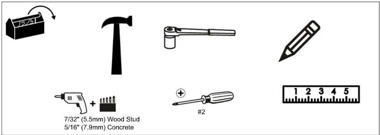
PARTS
![[A-P used on MSMU/MTMU Models Only] A (8) M4x16mm B (6) M4x20mm C (6) M4x25mm D (6) M5x16mm E (6) M5x20mm F (6) M5x25mm G (6) M6x16mm H (6) M6x25mm I (6) M8x20mm J (6) M8x30mm K (4) M8x50mm L (8) .750x.323x.250 M (8) .750x.344x.500 N (8) [Universal washer] P (1) M5 [In bag labeled "N"] S (1) [Security bracket] (MTM Only) T (1) [Security bracket] (MSM Only) [Interface brackets] (MSM Only) QA (4) 5/16" QB (4) 5/16" QC (4) 5/16" x 2-1/2" U (1) 3/16" - 6" V (1) W (1) [Interface brackets] (MTM Only) X (1) Y (1) [Included with MSM3XXX/MTM3XXX Models Only] Custom MSM6XXX/ MTM6XXX Hardware](/content/2026/06/1203821/images/ced9468c64fbcd7723278e8188c5896703f74477c59e2b23d959ea724723234c.jpg)
INSTALLATION
The MSM/MTM mounts are designed to be mounted to an 8" concrete, 8"x8"x16" concrete block or 2" x 4" wood studs (16" on center) wall. The MTM has brackets which allow the TV to be tilted. The MSM has static brackets which keep the TV in an upright position.
Locate Mounting Site

WARNING: IMPROPER INSTALLATION CAN LEAD TO MOUNT FALLING CAUSING SEVERE PERSONAL INJURY OR DAMAGE TO EQUIPMENT! It is the installers responsibility to make certain the structure to which the mount is being attached is capable of supporting five times the weight of the MTM or MSM and all attached equipment not to exceed 125 lbs (56.7 kg) for dual stud attachment, and 75 lbs (34.0 kg) for single stud attachment.
NOTE: Proceed to either the Installing to a Wood Stud Wall section or the Installing to a Concrete Wall section.
Installing to a Wood Stud Wall
- Determine the center of the TV screen, and where it should be located on the wall.
- Locate the closest stud to the left and right of the selected location.
NOTE: If the screen area lies over a stud, use that stud if using the single stud installation method.
NOTE: Use that stud and the stud to either the left or right of it if using the dual stud installation method. - Line up the notches on mount with center of screen marking to determine vertical center. (See Figure 1)
![Center of screen 7-1/2" [190.5mm] Vertical center of mount](/content/2026/06/1203821/images/17b601e8b84f301122665be60ddf3044a893422dd4bdcc91ddf81b49e49ac9c8.jpg)
Figure 1
- Measure up 7-1/2" (190.5mm) from the center point to mark location of the upper mounting slots.
- Using a level, mark the wall on each stud to attach the mount through the upper mounting slots. (See Figure 2)
NOTE: The MSM and MTM may be attached through the mounting slots on dual studs, or through the center mounting holes on a single stud. (See Figure 2)
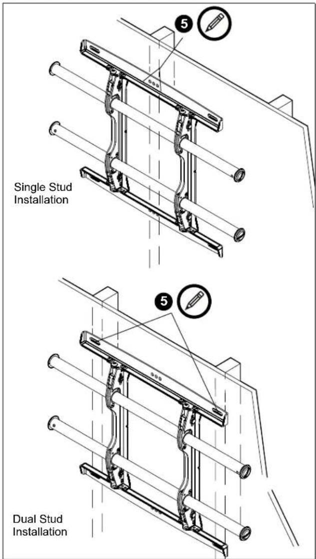
Figure 2

WARNING: ELECTRICAL SHOCK HAZARD! CUTTING OR DRILLING INTO ELECTRICAL CORDS OR CABLES CAN CAUSE DEATH OR SERIOUS PERSONAL INJURY! ALWAYS make certain area behind mounting surface is free of electrical wires and cables before drilling or installing fasteners.

WARNING: EXPLOSION AND FIRE HAZARD! CUTTING OR DRILLING INTO GAS PLUMBING CAN CAUSE DEATH OR SERIOUS PERSONAL INJURY! ALWAYS make certain area behind mounting surface is free of gas, water, waste, or any other plumbing before cutting, drilling, or installing fasteners.
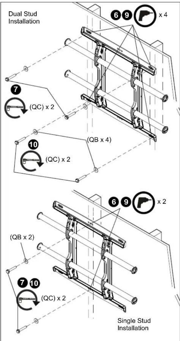
Figure 3
-
Drill one 7/32" (5.5mm) pilot hole in each stud.
-
Use two 5/16 x 2-1/2" lag bolts (QC) and two 5/16" flat washers (QB) [one lag bolt and washer for single stud installation] to attach top of mount to wall. (See Figure 3)
-
Mark the attachment points for the lower mounting slots, making sure the attachment points are located on the studs. (See Figure 3)
-
Drill 7/32" (5.5mm) pilot holes at markings for lower mounting holes. (See Figure 3)
- Use two 5/16 x 2-1/2" lag bolts (QC) and two 5/16" flat washers (QB) [one lag bolt and washer for single stud installation] to attach the mount to the wall through the lower mounting holes. (See Figure 3)
- Slide rails to approximate center of screen location.
Installing to a Concrete Wall
- Determine the center of the TV screen, and where it should be located on the wall.
- Line up the notches on mount with center of screen marking to determine vertical center. (See Figure 1)
- Measure up 7-1/2" (190.5mm) from the center point to mark location of the upper mounting slots. (See Figure 1)
- Using a level, mark the wall through both upper mounting slots. (See Figure 4)

WARNING: ELECTRICAL SHOCK HAZARD! CUTTING OR DRILLING INTO ELECTRICAL CORDS OR CABLES CAN CAUSE DEATH OR SERIOUS PERSONAL INJURY! ALWAYS make certain area behind mounting surface is free of electrical wires and cables before drilling or installing fasteners.

WARNING: EXPLOSION AND FIRE HAZARD! CUTTING OR DRILLING INTO GAS PLUMBING CAN CAUSE DEATH OR SERIOUS PERSONAL INJURY! ALWAYS make certain area behind mounting surface is free of gas, water, waste, or any other plumbing before cutting, drilling, or installing fasteners.
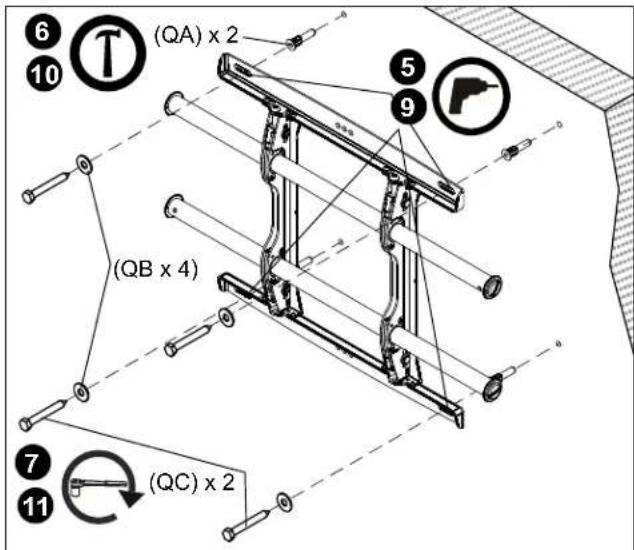
Figure 4
- Drill one 5/16" (7.9mm) pilot hole at each marking.
- Install an anchor (QA) into each pilot hole using a hammer.
-
Use two 5/16 x 2-1/2" lag bolts (QC) and two 5/16" flat washers (QB) to attach top of mount to anchors in wall.
-
Mark the attachment points for the lower mounting slots. (See Figure 4)
- Drill one pilot hole at each marking for lower mounting holes. (See Figure 4)
- Install an anchor (QA) into each pilot hole using a hammer.
- Use two 5/16 x 2-1/2" lag bolts (QC) and two 5/16" flat washers (QB) to attach the mount to the wall through the lower mounting holes. (See Figure 4)
- Slide rails to approximate center of screen location.
Attaching Interface Brackets to TV
- Align the center of the bracket with center of screen. (See Figure 5)
NOTE: The diamond-shape hole in the bracket corresponds to the center of the mount.
![[Brackets V and W shown] Pull strap Center of bracket](/content/2026/06/1203821/images/f21f0204dfdd886527608b391433f10b34456aa42a1db211bb0eb7a3e341ceda.jpg)
Figure 5

WARNING: IMPROPER INSTALLATION CAN LEAD TO DISPLAY FALLING CAUSING SERIOUS PERSONAL INJURY OR DAMAGE TO EQUIPMENT! Using screws of improper size may damage your display. Properly sized screws will easily and completely thread into display mounting holes. If spacers are required, be sure to use longer screws of the same diameter.
- Select correct screws, spacers (if necessary) and universal washers from the hardware bag (A-N) for MSMU/MTMU models; OR from the hardware bag included for MSM3XXX/MTM3XXX models, and attach brackets to back of screen. (See Figure 5)
Switching Interface Brackets (Optional)
If an installation situation makes adjusting the location of interface brackets necessary, there are several options.
- The wall bracket may be adjusted side to side at the point of attachment (mounting slots for dual stud installation, mounting holes for single stud installation). (See Figure 6)
- The location of the left and right interface brackets may be switched, with the knobs on the MTM interface brackets facing the inside of the mount. (See Figure 6)
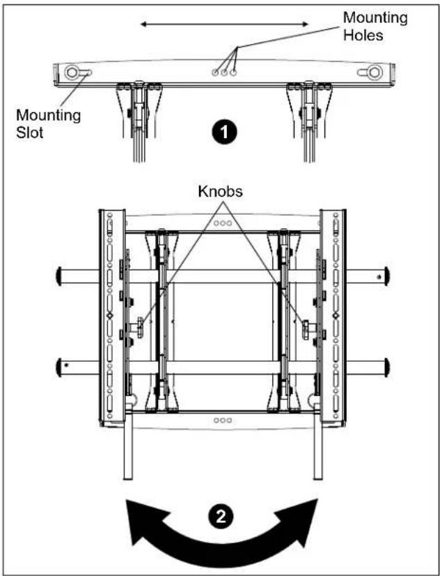
Figure 6
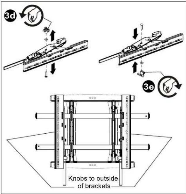
Figure 7
- If necessary, the tilt interface bracket knobs may be switched to allow the interface brackets to be reversed. (See Figure 7)
a. Remove display from mount.
b. Remove interface brackets from display.
c. Hold the right interface bracket horizontally, tightly gripping it so that spacers do not move.
d. Remove the knob, washer and screw.
e. Replace the knob, washer and screw in the opposite order, with the knob on the inside of the bracket.
f. Switch the right interface bracket to the left side of the wall mount.
g. Repeat Steps 3c through 3f with the left interface bracket.
Attaching Screen to Wall Mount
- Adjust Velcro® pullstrap (if necessary) so it does not extend beyond bottom of screen. (See Figure 8)
NOTE: Do NOT allow both interface brackets to be located on same side of wall bracket. (See Figure 8)
NOTE: NEVER place both interface brackets to one side of the wall mount center line! (See Figure 8)
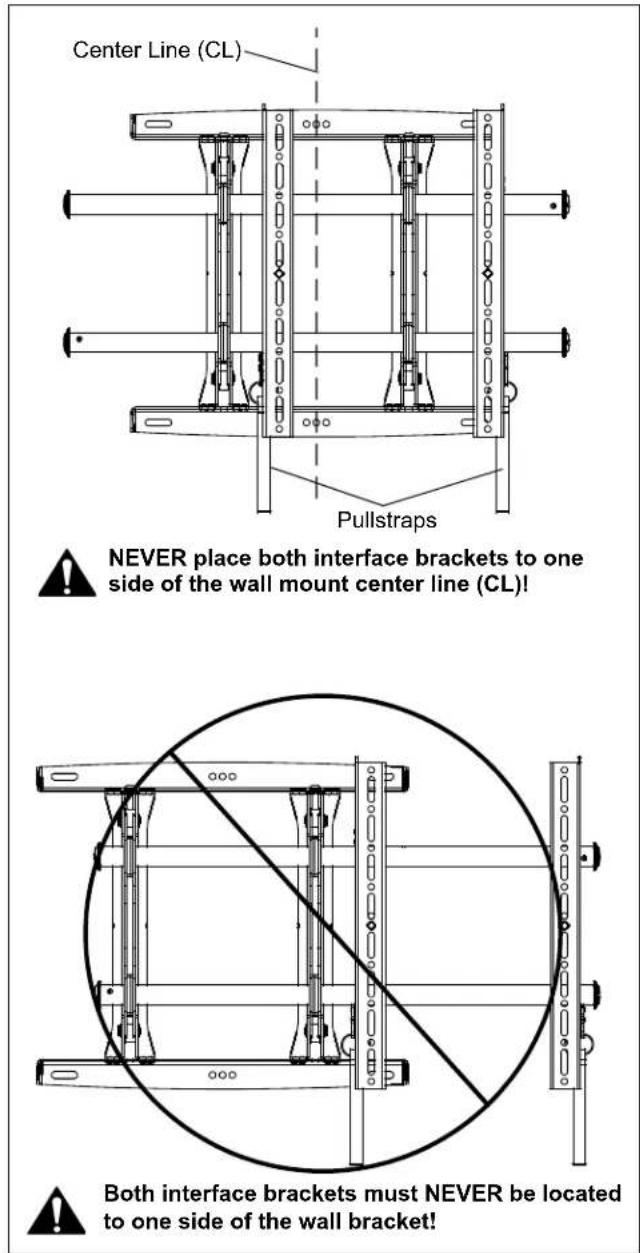
Figure 8
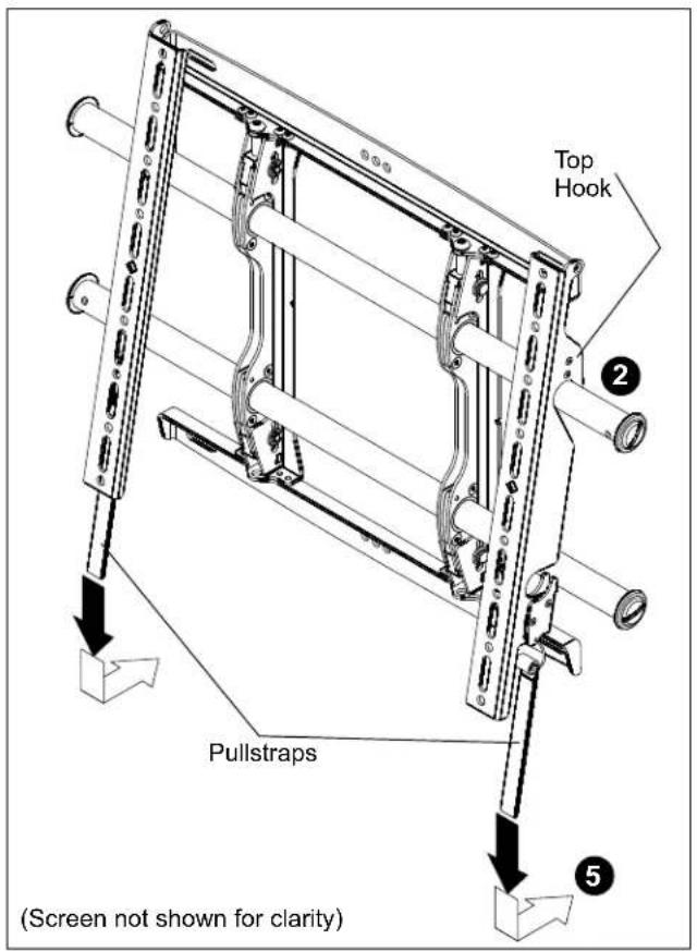
Figure 9
- Hang top hook of interface brackets onto the top bar of the mount. (See Figure 9)
NOTE: The screen initially installs into the "kickstand mode" to allow easy cable access.
-
Slide screen and bars to desired viewing position.
-
Route cables between wall and bars.

CAUTION: PINCH POINTS! Keep fingers, hands and cables out of pinch point areas.
- Pull downward on the pullstraps and swing inward toward wall, latching interface brackets to lower bar and locking bottom of screen to the mount. (See Figure 9)
Adjusting Roll/Height of Wall Brackets
NOTE: The height adjust wall bracket allows adjustment of ± 1/2".
-
Turn to right (tighten) to raise side of screen. (See Figure 10)
-
Turn to left (loosen) to lower side of the screen.
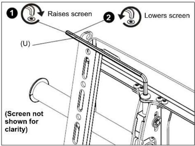
Figure 10
Locking Mount (Optional)
-
Add optional security bracket (S or T) to the mount. (See Figure 11)
-
Add padlock (not included) to complete security.
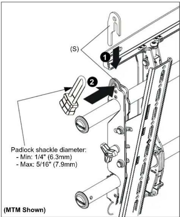
Figure 11
natural_image
Technical line drawing of a mechanical assembly with no visible text or symbols![16,00 [406.4] 8,00 [203.2] 1,00 [5.4] ,50 [2.7] Ø,33 [3.3] 2,00 [50.8] 11,13 [82.6] 1,75 [4.5] 15,10 [83.4] 1,00 [5.4] 18,79 [477.4] 25,57 [49.5]](/content/2026/06/1203821/images/9e37b2f6191ef4900802cf412ba25c8355ece70c70c66b67c62b5786d7599693.jpg)
![12° 4,83 [22.6] 16,53 [19.9]](/content/2026/06/1203821/images/302216594925a01c759dd7154e38959aa33d6bbb7bb3acf0661dea1e2d2b79e9.jpg)
![.38 [9,5] φ.32 [8,1] 7,87 [200] 6,36 [161,5] 5,91 [150] 4,39 [111,5] 3,94 [100] 2,42 [61,5] 1,97 [50] .45 [11,5] 0 .45 [11,5] 1,97 [50] 2,42 [61,5] 3,94 [100] 4,39 [111,5] 5,91 [150] 6,36 [161,5] 7,87 [200] 16,50 [419,1] 1,06 [27]](/content/2026/06/1203821/images/5fbe856855a75ed37ced6c6a2dbaeb7edce37cbc2e4c0ac59fb193f76f6abef5.jpg)
ЕДИНИЦЫ ИЗМЕРЕНИЯ: [МИЛЛИМЕТРЫ] ДЮЙМЫ
рис. 4
Our Mounts. Your Vision.
Chief, a products division of Milestone AV Technologies
8800-002499 Rev00
©2014 Milestone AV Technologies
www.chiefmfg.com
01/14
USA/International A 6436 City West Parkway, Eden Prairie, MN 55344
P 800.582.6480 / 952.225.6000
F 877.894.6918 / 952.894.6918
Europe A Franklinstraat 14, 6003 DK Weert, Netherlands
P +31 (0) 495 580 852
F +31 (0) 495 580 845
Asia Pacific A Office No. 1 on 12/F, Shatin Galleria
18-24 Shan Mei Street
Fotan, Shatin, Hong Kong
P 852 2145 4099
F 852 2145 4477