
PSS2535S - TV Stand Chief - Free user manual and instructions
Find the device manual for free PSS2535S Chief in PDF.


| Product Type | TV Stand |
| Brand | Chief |
| Model | PSS2535S |
| Dimensions (W x H x D) | 52.2 x 22.1 x 18.3 inches |
| Weight Capacity | 150 lbs |
| Material | Steel and tempered glass |
| Number of Shelves | 3 |
| Mounting Type | Freestanding |
| Color | Black |
| VESA Compatibility | Up to 200x200mm |
| TV Size Compatibility | 32 to 55 inches |
| Assembly Required | Yes |
| Included Hardware | Screws, bolts, and tools |
| Cable Management | Yes, built-in |
| Weight of Stand | 45 lbs |
| Maximum Screen Size | 55 inches |
| Load Capacity per Shelf | 30 lbs |
| Cleaning Instructions | Wipe with a damp cloth; avoid abrasive cleaners |
| Warranty | 1 year limited |
| Recommended Use | Home theater or entertainment center |
Frequently Asked Questions - PSS2535S Chief
User questions about PSS2535S Chief
0 question about this device. Answer the ones you know or ask your own.
Ask a new question about this device
Download the instructions for your TV Stand in PDF format for free! Find your manual PSS2535S - Chief and take your electronic device back in hand. On this page are published all the documents necessary for the use of your device. PSS2535S by Chief.
USER MANUAL PSS2535S Chief
INSTALLATION INSTRUCTIONS

natural_image
Technical line drawing of a mechanical assembly with mounting base and mounting bracket (no text or symbols)PLASMA SWIVEL STAND
DISCLAIMER
Milestone AV Technologies and its affiliated corporations and subsidiaries (collectively "Milestone"), intend to make this manual accurate and complete. However, Milestone makes no claim that the information contained herein covers all details, conditions or variations, nor does it provide for every possible contingency in connection with the installation or use of this product. The information contained in this document is subject to change without notice or obligation of any kind. Milestone makes no representation of warranty, expressed or implied, regarding the information contained herein. Milestone assumes no responsibility for accuracy, completeness or sufficiency of the information contained in this document.
Chief® and ClickConnect™ are registered trademarks of Milestone AV Technologies. All rights reserved.

IMPORTANT WARNINGS AND
CAUTIONS!

WARNING: A WARNING alerts you to the possibility of serious injury or death if you do not follow the instructions.

CAUTION: A CAUTION alerts you to the possibility of damage or destruction of equipment if you do not follow the corresponding instructions.

WARNING: Failure to read, thoroughly understand, and follow all instructions can result in serious personal injury, damage to equipment, or voiding of factory warranty! It is the installer's responsibility to make sure all components are properly assembled and installed using the instructions provided.

WARNING: Failure to provide adequate structural strength for this component can result in serious personal injury or damage to equipment! It is the installer's responsibility to make sure the structure to which this component is attached can support five times the combined weight of all equipment. Reinforce the structure as required before installing the component.

WARNING: Exceeding the weight capacity can result in serious personal injury or damage to equipment! It is the installer's responsibility to make sure the combined weight of all components located on the PSS2000 does not exceed 150 lbs (68.04 kg).
DIMENSIONS
![TOP MOUNTING BUTTON ON PSB-XXXX DRAWING GOES HERE [413] 16.27 [29] 1.14 [20] .78 [362] 14.25 [31] 1.22 [64] 2.50 MIN 20.72 MAX 27.47 [80] 3.16 [236] 9.29 NOTE: CUSTOM INTERFACE BRACKET NOT SHOWN. THE CUSTOM INTERFACE BRACKET NEEDED FOR YOUR DISPLAY WILL ADD BETWEEN 1/2" AND 2" IN DEPTH AND MAY AFFECT LOCATION OF DISPLAY ON THE MOUNT. SEE PSB-XXXX DRAWING ALSO.](/content/2026/06/1247944/images/a50146ba157b18e4c0af30204bc58ecff1a9d9bd6938fa9a0668d0ae520a5db6.jpg)
LEGEND
 | Tighten Fastener |
| Apretar elemento de fijación | |
| Befestigungsteil festziehen | |
| Apertar fixador | |
| Serrare il fissaggio | |
| Bevestiging vastdraaien | |
| Serrez les fixations | |
 | Loosen Fastener |
| Aflojar elemento de fijación | |
| Befestigungsteil lösen | |
| Desapertar fixador | |
| Allentare il fissaggio | |
| Bevestiging losdraaien | |
| Desserrez les fixations | |
 | Phillips Screwdriver |
| Destornillador Phillips | |
| Kreuzschlitzschraubendreher | |
| Chave de fendas Phillips | |
| Cacciavite a stella | |
| Kruiskopschroevendraaier | |
| Tournevis à pointe cruciforme | |
 | Open-Ended Wrench |
| Llave de boca | |
| Gabelschlüssel | |
| Chave de bocas | |
| Chiave a punte aperte | |
| Steeksleutel | |
| Clé à fourche | |
 | By Hand |
| A mano | |
| Von Hand | |
| Com a mão | |
| A mano | |
| Met de hand | |
| À la main | |
 | Hex-Head Wrench |
| Llave de cabeza hexagonal | |
| Sechskantschlüssel | |
| Chave de cabeça sextavada | |
| Chiave esagonale | |
| Zeskantsleutel | |
| Clé à tête hexagonale |





Pencil Mark
Marcar con lápiz
Stiftmarkierung
Marcar com lápis
Segno a matita
Potloodmerkteken
Marquage au crayon
Drill Hole
Perforar
Bohrloch
Fazer furo
Praticare un foro
Gat boren
Percez un trou
Adjust
Ajustar
Einstellen
Ajustar
Regolare
Afstellen
Ajuster
Remove
Quitar
Entfernen
Remover
Rimuovere
Verwijderen
Retirez
Optional
Opcional
Optional
Opcional
Opzionale
Optie
En option
Security Wrench
Llave de seguridad
Sicherheitsschlüssel
Chave de segurança
Chiave di sicurezza
Veiligheidssleutel
Clé de sécurité
TOOLS REQUIRED FOR INSTALLATION

PARTS
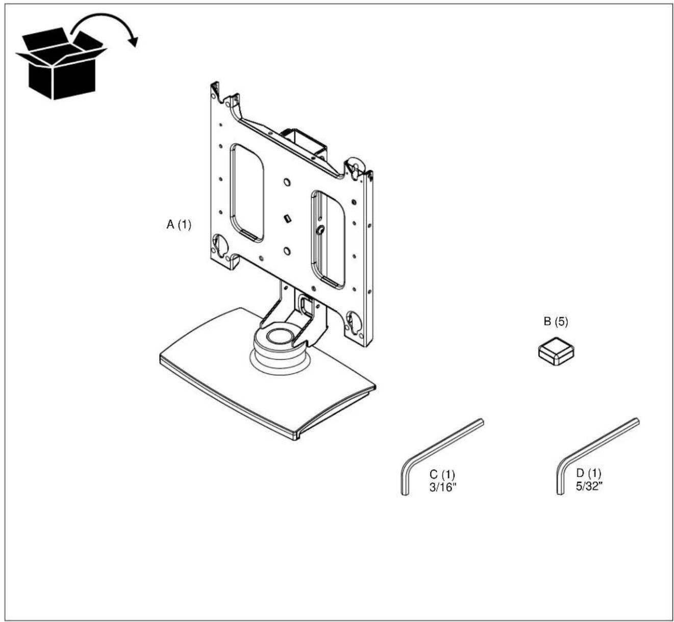
INSTALLATION
NOTE: For free-standing applications only, install five rubber bumpers (B) onto bottom of stand (A). (See Figure 1)

Figure 1
Stand Assembly
NOTE: PSS2000 ships assembled for displays 30" in height or less, and lowered to its minimum height.
Display Height 30 Inches or Smaller
- Loosen the four height adjustment screws and raise the slide with faceplate to its maximum height. (See Figure 2)
- Raise slide to the maximum height.
- Secure slide in place by tightening the four height adjustment screws. (See Figure 2)
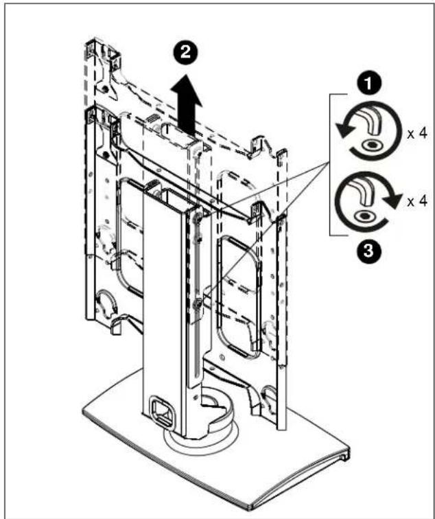
Figure 2
Display Height Greater Than 30 Inches
- Remove slide from base by removing four button head cap screws and four flat washers. (See Figure 3)
- Remove faceplate from slide by removing two flat washers and two lock nuts. (See Figure 3)

Figure 3
- Install faceplate into upper mounting holes of slide using two flat washers and two lock nuts removed in Step 2.
- Install slide onto base using four button head cap screws and four flat washers removed in Step 1.
NOTE: Do NOT fully tighten slide mounting screws at this time.
- Raise slide to maximum height.
- Tighten four height adjustment screws. (See Figure 2)
Site Preparation

WARNING: EXCEEDING WEIGHT CAPACITY CAN RESULT IN SERIOUS PERSONAL INJURY OR DAMAGE TO EQUIPMENT! It is the installer's responsibility to make sure the combined weight of all components does not exceed 150 lbs (68.04 kg).

CAUTION: TURNING DISPLAY CAN CAUSE DAMAGE TO SURROUNDING OBJECTS. Make certain location provides enough area for the display to rotate ±45irc without being obstructed.
NOTE: See Display Stop Location Adjustment section for information on adjusting rotation.
- Locate a flat dry surface on which to mount the PSS2000 assembly.
- Measure the hole locations on bottom of PSS2000 and mark the four mounting hole locations on mounting surface. (See Figure 4)
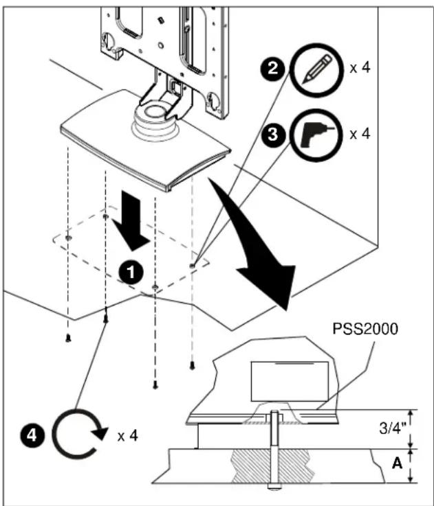
Figure 4
- Drill four 1/4" diameter holes through mounting surface at marks.
- Secure mount to mounting surface using four 1/4-20 cap screws with a length equal to the thickness of the mounting surface A plus 3/4". (See Figure 4)
Display Installation
The following procedure assumes that the proper interface bracket for the display being mounted has already been installed on the display.
If no interface bracket is present on display, install bracket to display using the instructions included with the interface bracket before proceeding.
If an interface bracket for the display being mounted needs to be obtained, or additional assistance is required, contact Chief.
To install the display:
- While supporting both sides of display, align four mounting buttons on display or interface bracket with four mounting holes in faceplate.
- Lower display into place listening for audible "click" to ensure recessed area of mounting buttons are properly seated in lower area of mounting holes and ClickConnect mechanism has engaged. (See Figure 1)
NOTE: Holes are provided in the faceplate for use with a padlock or similar locking device, if desired. In addition, the pin and nut may be removed from the upper holes and moved to the lower holes for use as a more permanent locking device.

Figure 5
Stand Adjustment
Adjusting Display Height

CAUTION: DO NOT ALLOW DISPLAY TO DROP TO BOTTOM OF STAND. Displays are fragile and may be damaged.
- Hold display in place and loosen the four height adjustment screws. (See Figure 2)
- Position display to the desired height.
- Tighten the four height adjustment screws. (See Figure 2)
Adjusting Stand Tension
- Check swivel tension while display is attached to the stand.
- If tension adjustment is necessary, slightly tighten or loosen adjustment screws on bottom of PSS2000. (See Figure 6)

Figure 6
Adjusting Swivel Stops
- Decide the amount of desired stand swivel (15°, 25° or 35°).
- Insert a 10-24 x 1/2" screw (not provided) in one of the three swivel stop holes in the stand base. (See Figure 7)
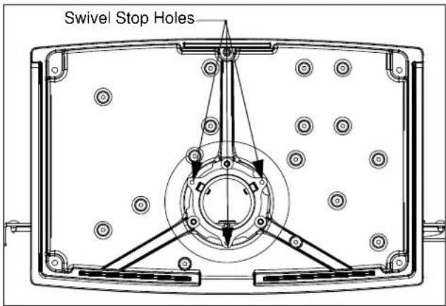
Figure 7
Adjusting Display Roll
- Loosen upper and lower roll adjustment nuts.(See Figure 8)
- Level display.
- Tighten roll adjustment nuts.

Figure 8
Cable Routing and Management

WARNING: ELECTRICAL SHOCK HAZARD! Improper routing can lead to wires or cables being damaged. Make certain display power cable is not routed through areas where it can be pinched or cut.
- Route display cables and wiring through cable management hole in base. (See Figure 9)
NOTE: Cables may also be routed through a hole in the mounting surface.
- Connect wires and cables to display.

natural_image
Technical line drawing of a mechanical assembly with labeled components (no text or symbols present)Figure 9

CHIEF®
Our Mounts. Your Vision.
Chief Manufacturing, a division of Milestone AV Technologies
8800-000070
©2008 Milestone AV Technologies
www.chiefmfg.com
10/08
USA/International A 8401 Eagle Creek Parkway, Savage, MN 55378
P 800.582.6480 / 952.894.6280
F 877.894.6918 / 952.894.6918
Europe A Fellenoord 130 5611 ZB EINDHOVEN, The Netherlands
P +31 (0)40 2668620
F +31 (0)40 2668615
Asia Pacific A Room 24F, Block D, Lily YinDu International Building
LuoGang, BuJi Town, Shenzhen, CHINA.


- INSTALLATION INSTRUCTIONS
- DISCLAIMER
- IMPORTANT WARNINGS AND
- CAUTIONS!
- DIMENSIONS
- LEGEND
- Pencil Mark
- Drill Hole
- Adjust
- Remove
- Optional
- Security Wrench
- INSTALLATION
- Stand Assembly
- Display Height 30 Inches or Smaller
- Display Height Greater Than 30 Inches
- Site Preparation
- Display Installation
- Stand Adjustment
- Adjusting Display Height
- Adjusting Stand Tension
- Adjusting Swivel Stops
- Adjusting Display Roll
- Cable Routing and Management
- CHIEF®
Brand : Chief
Model : PSS2535S
Category : TV Stand