Legacy V4 - PC Case Rosewill - Free user manual and instructions
Find the device manual for free Legacy V4 Rosewill in PDF.

User questions about Legacy V4 Rosewill
0 question about this device. Answer the ones you know or ask your own.
Ask a new question about this device
Download the instructions for your PC Case in PDF format for free! Find your manual Legacy V4 - Rosewill and take your electronic device back in hand. On this page are published all the documents necessary for the use of your device. Legacy V4 by Rosewill.
USER MANUAL Legacy V4 Rosewill
User's ManualLegacy VAASE
User's ManualLega
Specification
| Material | 1.5mm Aluminum Alloy |
| Dimension | 238mm x 280mm x 278mm (WxDxH) |
| Motherboard | Micro-ATX / ITX |
| Drive Bay | 2 x 3.5", 1 x 2.5" or 3 x 3.5" |
| Cooling System | 3 x 80mm Fans (optional) |
| Fan Speed Controller | 3 level of fan speed (optional) |
| Expansion Slot | 4 |
| CPU Cooler | Not Higher Than 120mm |
| Display Card | Not Longer Than 260mm |
| Front I/O Port | 1 x USB3.0, 1 x USB2.0, 1 x MIC, 1 x Audio |
| Power Supply | Standard ATX PSII PSU |
| Weight | 2.0 kg |
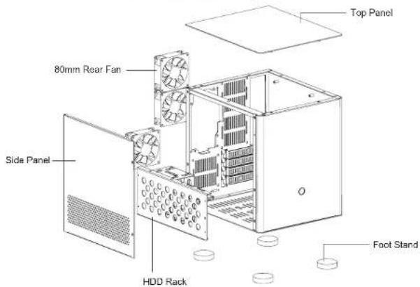
Disassemble Chart Fans are NOT INCLUDED.
text_image
Top Panel 80mm Rear Fan Side Panel HDD Rack Foot StandAccessory Box
| (HZW7) | For locking 3.5"HDD | 12PCS | For locking 2.5"HDD | 4PCS |
| (bccs) | For lockingmotherboard and PSU | 9PCS | For locking foot | 4PCS |
| (fccs) | Gold stamping drawbenchaluminum foot | 4PCS | Stand-off for motherboard | 3PCS |
| (sw7) | For binding cables | 3PCS | HDD rubber | 4PCS |

connectors
| USB 2.0 Connection | USB 3.0 Connection | Hard drive LED Connection |


[Non-Text]

CASE
User's ManualLegacy VAASE
User's ManualLega
Installation Guide
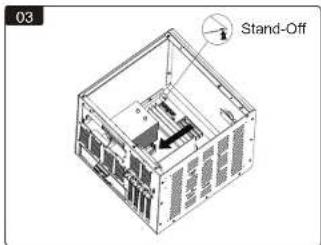
natural_image
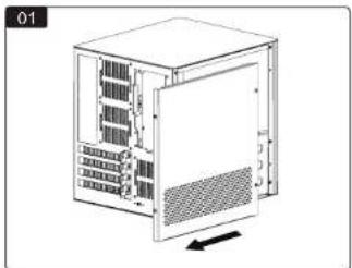
Diagram of a server rack unit with internal components and a directional arrow (no text or symbols)Unscrew the 4 screws to remove the side panel. Insta
flowchart
graph TD
    A["Device Board"] --> B["Switch"]
    B --> C["Electrical Control Panel"]
r 1 x 3.5" HDD or 1 x 2.5" SSD on the base panel.(HDD rubbers can be found in the accessory box).
natural_image
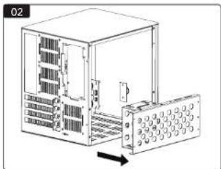
Diagram of a server rack unit with internal components and an external panel (no text or symbols visible)Remove the HDD rack.
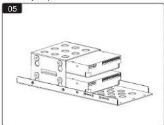
natural_image
Technical line drawing of a multi-tiered electronic device with mounting holes and connectors (no text or symbols)Install the 3.5" HDDs.
text_image
03 Stand-OffInstall the motherboard with 4 screws and stand-offs; install the display card.
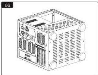
natural_image
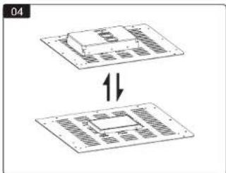
Technical line drawing of a computer chassis with ventilation grilles and ports (no text or symbols)Install the PSU; install the HDD rack; install the feet.
4
© All rights reserved by Rosewell
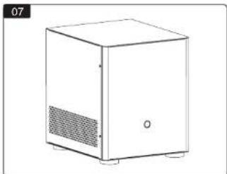
natural_image
Line drawing of a white cabinet with ventilation grilles and a small door (no text or symbols)Reinstall the side panel. Assembly complete.
Thank you for purchasing a High-Quality Rosewill Product.
Please register your product at: http://www.rosewill.com
for complete warranty information and future support for your product.
If you have any question while using our products, please visit our website: www.rosewill.com for latest driver & user manual or feel free to contact us.
Support Phone Number: 800-575-9885
Support Email: techsupport@rosewill.com
© All rights reserved by Rosewell