Galaxy - Computer Case Rosewill - Free user manual and instructions
Find the device manual for free Galaxy Rosewill in PDF.

User questions about Galaxy Rosewill
0 question about this device. Answer the ones you know or ask your own.
Ask a new question about this device
Download the instructions for your Computer Case in PDF format for free! Find your manual Galaxy - Rosewill and take your electronic device back in hand. On this page are published all the documents necessary for the use of your device. Galaxy by Rosewill.
USER MANUAL Galaxy Rosewill
Installing Power Supply P.4
Installing Motherboard P.5
Installing Add On Card P.5
Installing External 5.25"/3.5" Device (Galaxy 01) P.6
Installing External 5.25"/3.5" Device (Galaxy 02/03) P.7
Installing 3.5"/2.5" HDD/SSD P.8
■ Information P.9
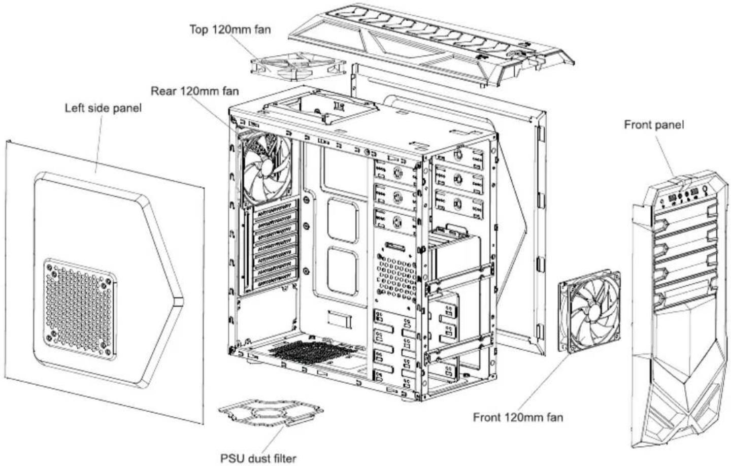
Disassemble Chart
( For reference only. Models' option may be varied by countries. )
text_image
Top 120mm fan Rear 120mm fan Left side panel Front panel PSU dust filter Front 120mm fanFront I/O Pin Define
(Please refer to your motherboard's user's manual to connect.)
| USB 3.0 CONNECTOR | AC97 CONNECTOR | ||
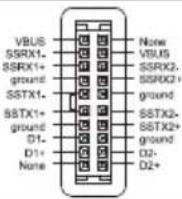 |  | 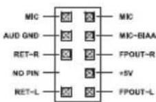 | 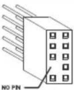 |
| USB2.0 CONNECTOR | HD CONNECTOR | ||
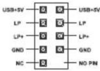 | 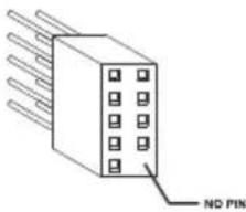 | 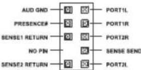 | 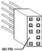 |
Accessory Box
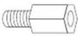 | 9 x M/B standoff(6 Pre-Installed) | Motherboard |
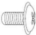 | 29 x screw-A | Motherboard5.25"/3.5" Device2.5" SSD/HDD |
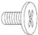 | 16 x screw-B 3.5" HDD | |
 | 11 x screw-C | Power SupplyAdd-on Card |
 | 1 x 5.25" to 3.5" bayconverter (Galaxy 2/3 only) | External 3.5"Device |
 | 1 x PC Speaker Motherboard | |
 | 5 x Cable tie Cables | |
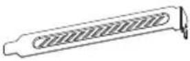 | 2 x PCI cover | Expansion Slot |
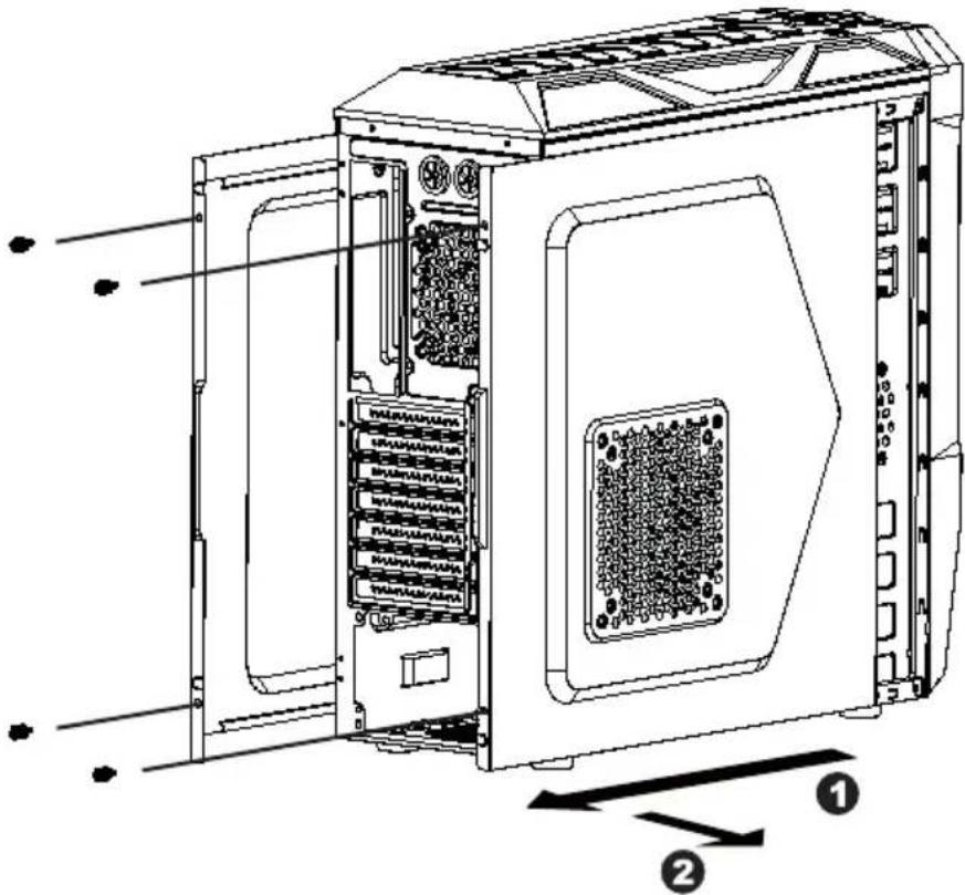
1. Opening Chassis
text_image
Technical diagram of a computer tower with labeled components and directional arrows indicating assembly or movement.Unscrew to remove left and right panels.
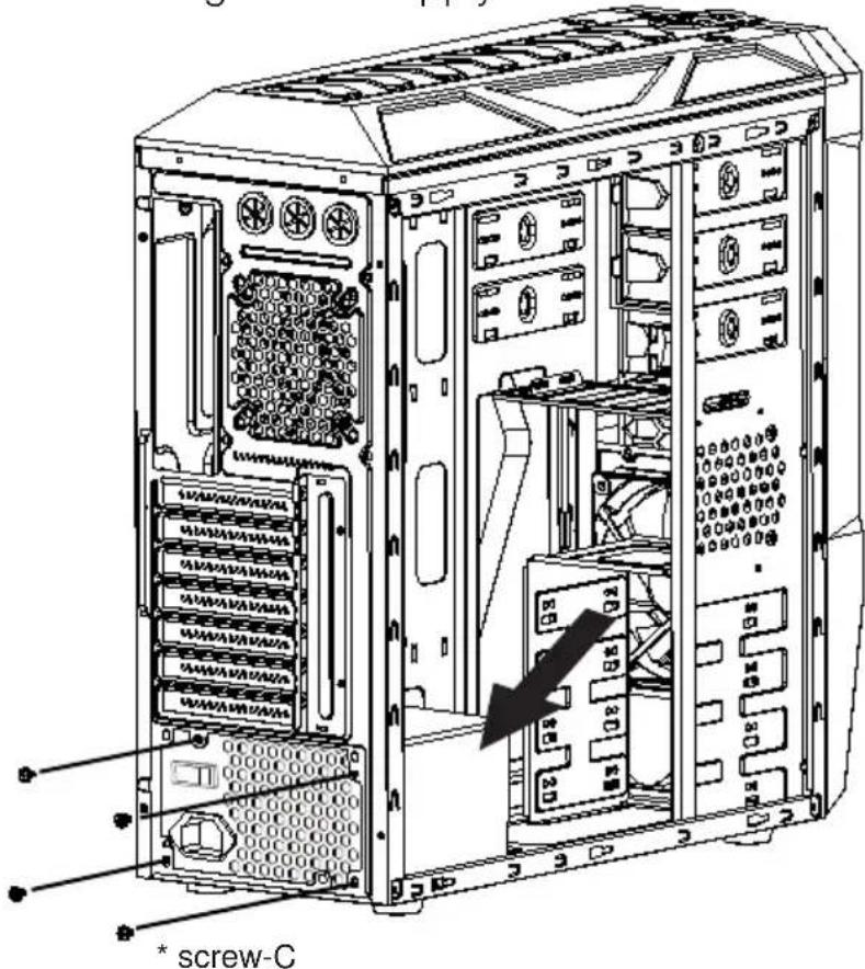
2. Installing Power Supply
text_image
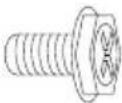
screw-CPlace the power supply from the left side into the chassis and secure with screws.
NOTICE :
-If your power supply is equipped with single fan (120mm, 135mm or 140mm), please have the fan face to the bottom.
-Please remember to clean the PSU dust filter regularly.
To Remove PSU dust filter for Cleaning:
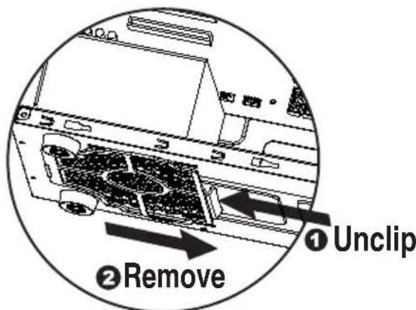
text_image
① Unclip ② Remove3. Installing Motherboard
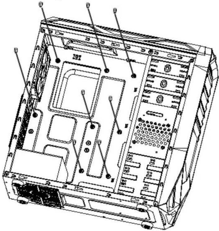
text_image
Technical diagram of a computer tower with labeled ports and internal compartmentsStep 1- Install motherboard stand-offs according to your motherboard's form factor.
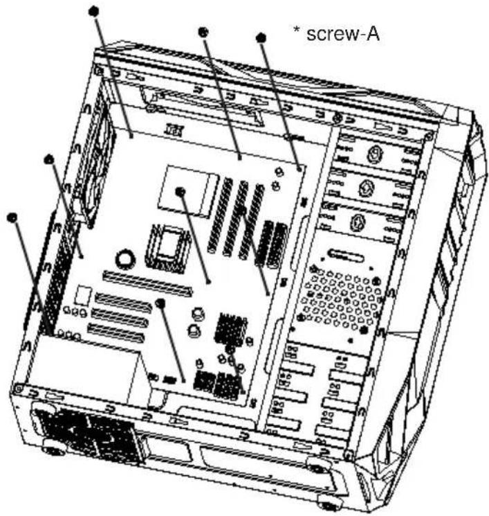
text_image
* screw-AStep 2- Place the motherboard onto stand-offs and secure with screws.
NOTE : NOT every motherboard is made by standard, please set stand-offs according to your motherboard.
4. Installing Add On Card
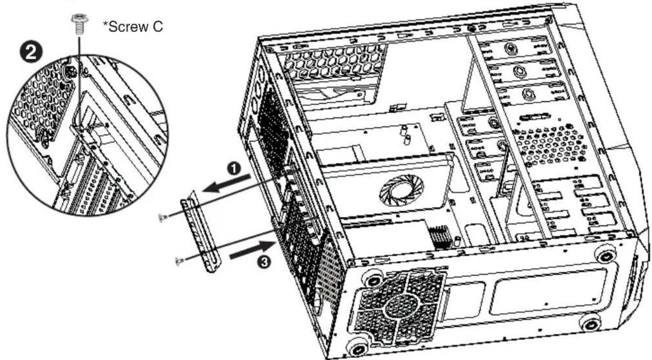
text_image
*Screw C ② ① ③Step 1- Unscrew and remove add-on card cover.
Step 2- Install VGA card and secure with screw.
Step 3- Put back add-on card cover and secure with screws.
5. Installing External 5.25"/3.5" Device (Applies to Galaxy-01)
*Please refer to the next page for Galaxy-02/03 external drive installation
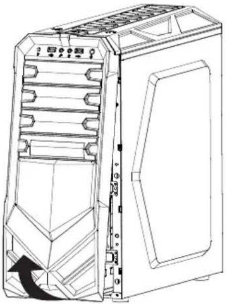
natural_image
Line drawing of a desktop computer tower case with visible internal components and an arrow indicating a rotation or movement (no text or symbols)-Remove front panel by pulling from the bottom as shown.
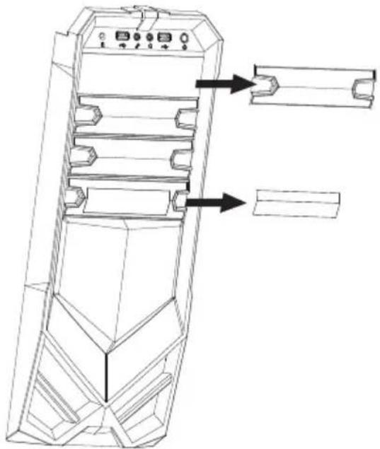
natural_image
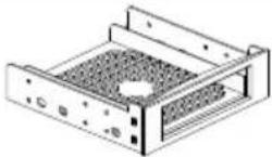
Technical line drawing of a mechanical device with internal components and directional arrows indicating assembly or movement (no text or symbols)-Confirm which bay(s) you want to install device(s) then remove the bay cover.
6. Installing External 5.25"/3.5" Device (Applies to Galaxy-01)
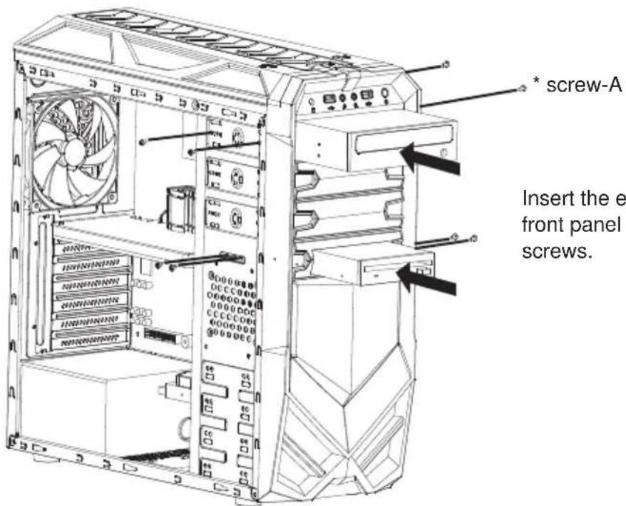
text_image
* screw-A Insert the e front panel screws.Insert the external 5.25" & 3.5" device from the front panel into the chassis then secure with screws.
5a. Installing External 5.25"/3.5" Device (Applies to Galaxy-02/03)
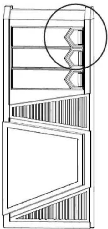
natural_image
Technical line drawing of a multi-level cabinet or elevator unit with a circular inset detail (no text or symbols)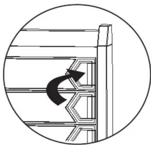
natural_image
Diagram showing a curved arrow inside a structural frame, enclosed in a circle (no text or symbols)-For Galaxy 2/3, 5.25" bay cover can be removed by releasing the locking mechanism on the cover.
6a. Installing External 5.25"/3.5" Device (Applies to Galaxy-02/03)
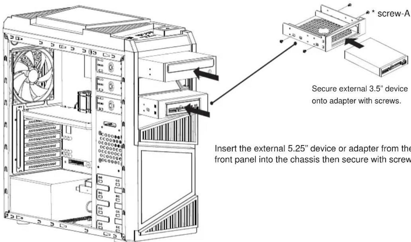
text_image
Secure external 3.5" device onto adapter with screws. Insert the external 5.25" device or adapter from the front panel into the chassis then secure with screwInsert the external 5.25" device or adapter from the front panel into the chassis then secure with screws.
7. Installing 3.5"/2.5" HDD/SSD
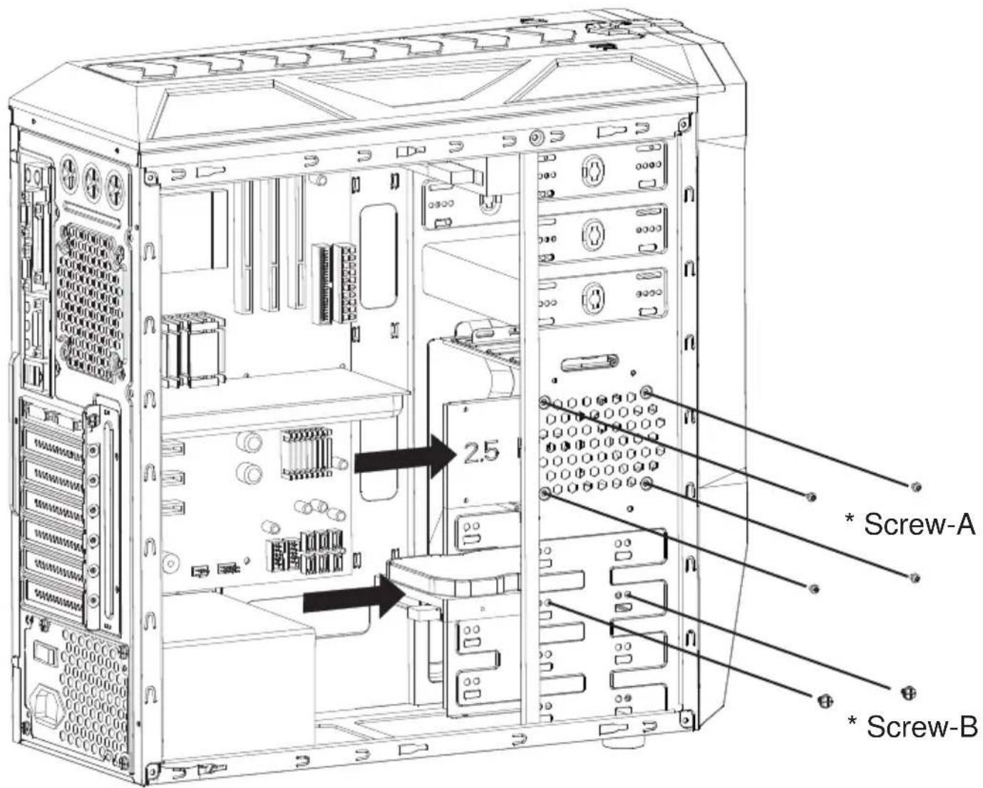
text_image
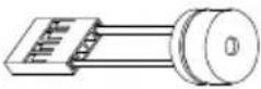
2.5 * Screw-A * Screw-BPut the 3.5"/2.5" HDD/SSD onto the HDD tray then secure with screws.
8. Closing Chassis
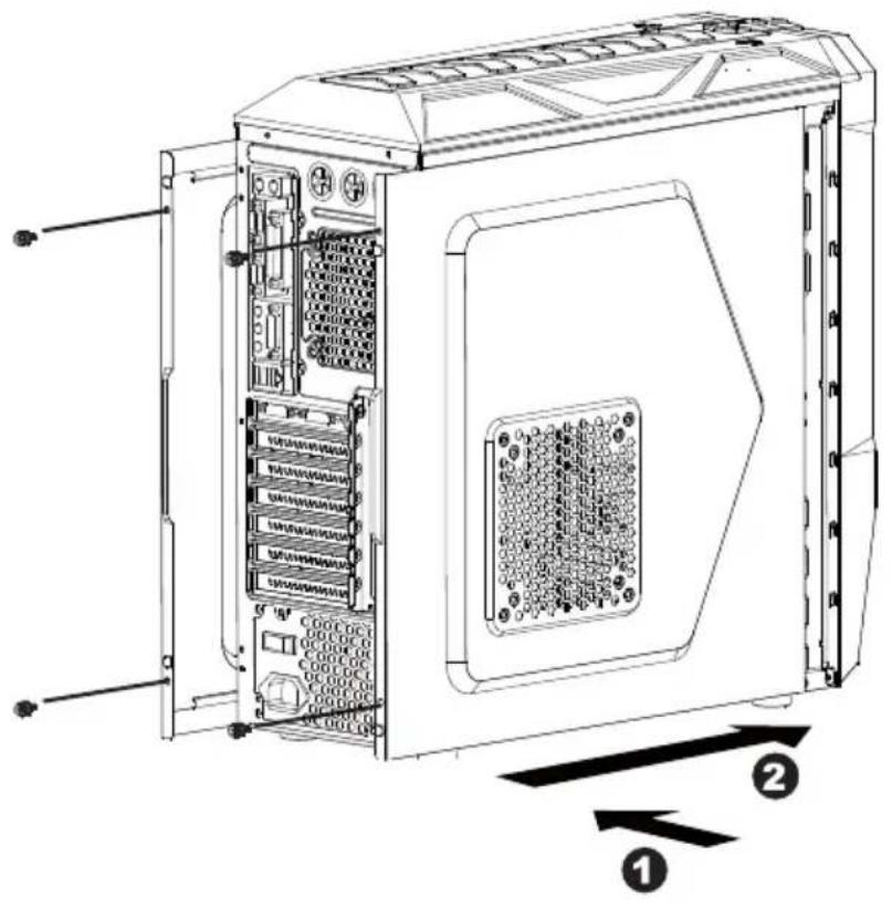
text_image
Technical diagram of an internal server rack with labeled components and directional arrows indicating flow or movement.Make sure all necessary cables and wires are connected, then reinstall side panels and secure with screws.
Thank you for purchasing a High-Quality Rosewill Product.
Please register your product at : http://www.rosewill.com for complete warranty information and future support for your product.
If you have any question while using our products, please visit our website: www.rosewill.com for latest driver & user manual or feel free to contact us.
Support Phone Number: 800-575-9885 Support Email: techsupport@rosewill.com