Challenger-S - Computer Case Rosewill - Free user manual and instructions
Find the device manual for free Challenger-S Rosewill in PDF.

| Product Type | Computer Case |
| Model | Challenger-S |
| Form Factor | Mid Tower |
| Motherboard Support | ATX, Micro-ATX, Mini-ITX |
| Dimensions (L x W x H) | 18.5 x 7.5 x 17.5 inches (470 x 190 x 445 mm) |
| Weight | 11.5 lbs (5.2 kg) |
| Material | Steel, Plastic |
| External Drive Bays | 3 x 5.25" |
| Internal Drive Bays | 4 x 3.5", 2 x 2.5" |
| Expansion Slots | 7 |
| Front I/O Ports | 2 x USB 2.0, 1 x USB 3.0, Audio In/Out |
| Power Supply Support | Standard ATX (not included) |
| Max PSU Length | 180 mm |
| Max GPU Length | 350 mm |
| Max CPU Cooler Height | 160 mm |
| Cooling System (Pre-installed) | 1 x 120mm Front, 1 x 120mm Rear |
| Additional Cooling Options | Up to 2 x 120mm Top, 1 x 120mm Side |
| Side Panel | Windowed (Acrylic) |
| Tool-less Design | Yes (for 5.25" & 3.5" drives) |
| Cleaning Instructions | Use a soft dry cloth; avoid liquids |
| Safety Precautions | Keep away from moisture; ensure proper grounding |
| Spare Parts Availability | Replacement fans, screws, and filters available |
| Warranty | Limited 1-year warranty |
Frequently Asked Questions - Challenger-S Rosewill
User questions about Challenger-S Rosewill
0 question about this device. Answer the ones you know or ask your own.
Ask a new question about this device
Download the instructions for your Computer Case in PDF format for free! Find your manual Challenger-S - Rosewill and take your electronic device back in hand. On this page are published all the documents necessary for the use of your device. Challenger-S by Rosewill.
USER MANUAL Challenger-S Rosewill
Install Power Supply P.5
Install Motherboard & Add-in Card P.6
Install External 5.25" Device P.7
Install 3.5"/2.5" HDD/SSD P.8
System Ready P.8
Clean the Dust Filters P.9
Optional: Additional Fan & Liquid Cooling Radiator P.10
Thank you for purchasing a High-Quality Rosewill Product.
Please register your product at: http://www.rosewill.com
for complete warranty information and future support for your product.
If you have any questions while using our products, please visit our website: www.rosewill.com for latest driver & user manual.
Support Phone Number: 800-575-9885
Support Email: techsupport@rosewill.com
Disassembling Chart (Components vary by country)
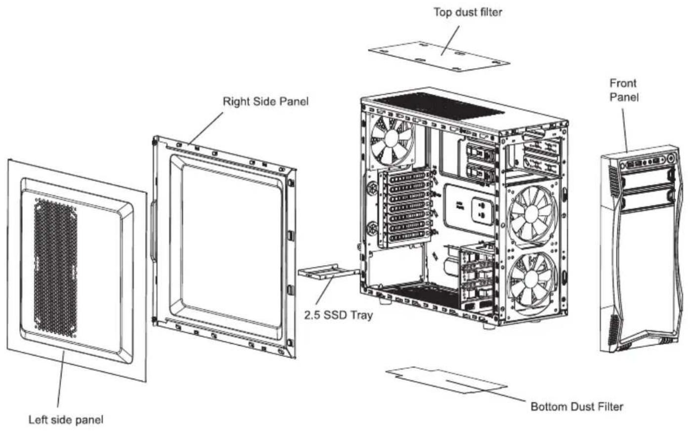
text_image
Top dust filter Right Side Panel 2.5 SSD Tray Front Panel Left side panel Bottom Dust FilterFront I/O Cable Pinout (Please refer to your motherboard's user manual to connect.)
| USB 3.0 CONNECTOR | USB2.0 CONNECTOR | HD Audio CONNECTOR | ||
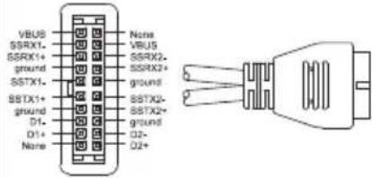 | 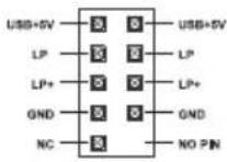 | 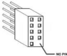 | 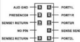 | 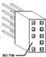 |
Top I/O
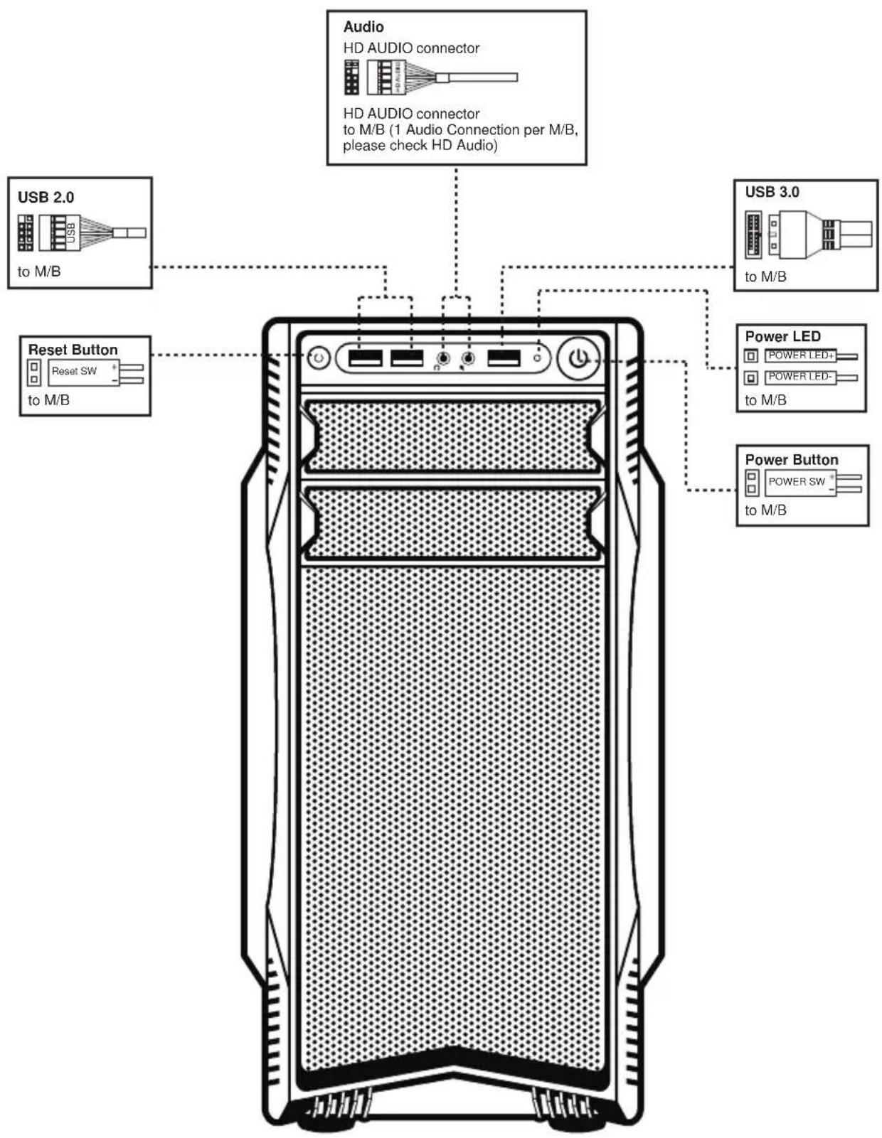
text_image
Audio HD AUDIO connector HD AUDIO connector to M/B (1 Audio Connection per M/B, please check HD Audio) USB 2.0 to M/B Reset Button Reset SW to M/B USB 3.0 to M/B Power LED POWER LED+ POWER LED- to M/B Power Button POWER SW to M/BAccessory Box
| Part's Name FunctionFigure | ||||
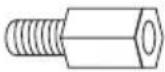 | 9x M/B Standoff | Motherboard | ||
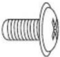 | 12x Screw - A | Motherboard5.25/3.5 Device2.5 SSD/HDD | ||
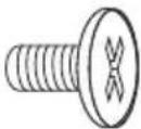 | 9x Screw - B 3.5 | HDD | ||
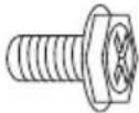 | 4x Screw - C | Power SupplyAdd-in Card | ||
 | 1x Buzzer | Motherboard | ||
 | 3x Cable Tie | CableManagement | ||
 |  |  | 1x Nut Setter | Motherboard |
Installation Guide
1. Open Chassis
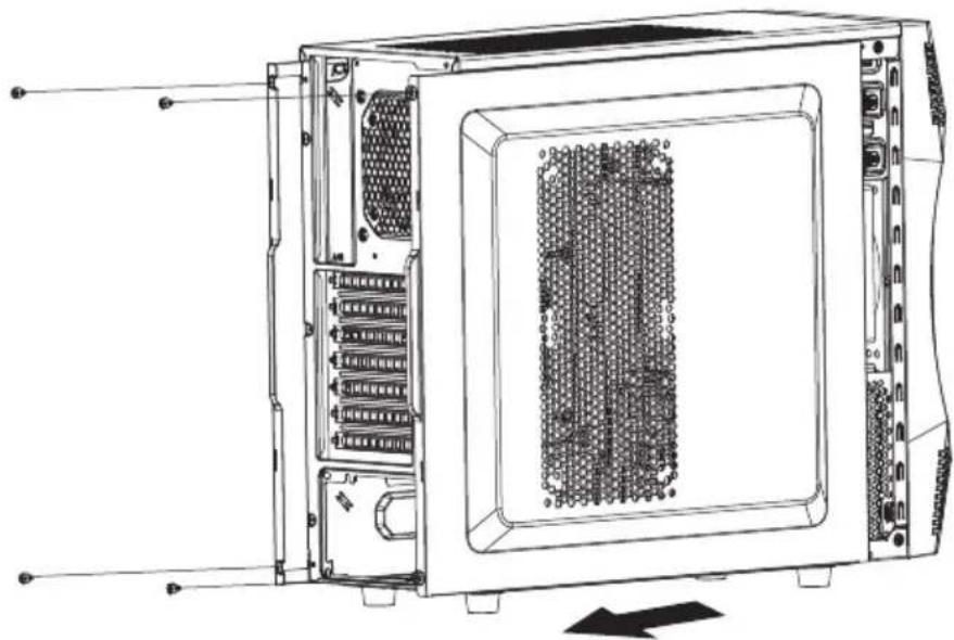
natural_image
Technical line drawing of a server rack unit with internal components and ventilation slots (no text or labels)1-1 Remove the thumbscrews and slide both side panels out.
2. Install Power Supply
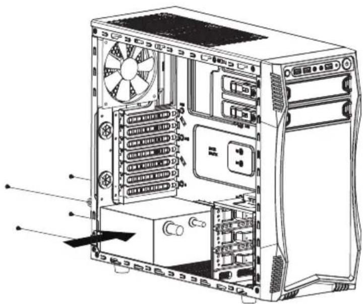
natural_image
Technical line drawing of a desktop computer tower showing internal components like drive bays and fan (no text or labels)2-1 Seat the power supply unit on the bottom of the case and secure with screw-C. If the PSU is equipped with single fan, you may have two options of installation:
- Fan Facing Upwards: No special requirements.
- Fan Facing Downwards: Make sure that there is enough room for air-intake between the bottom of case and the surface where the case is located.
- Clean the dust filter regularly to ensure adequate airflow.
3. Install Motherboard & Add-in Card
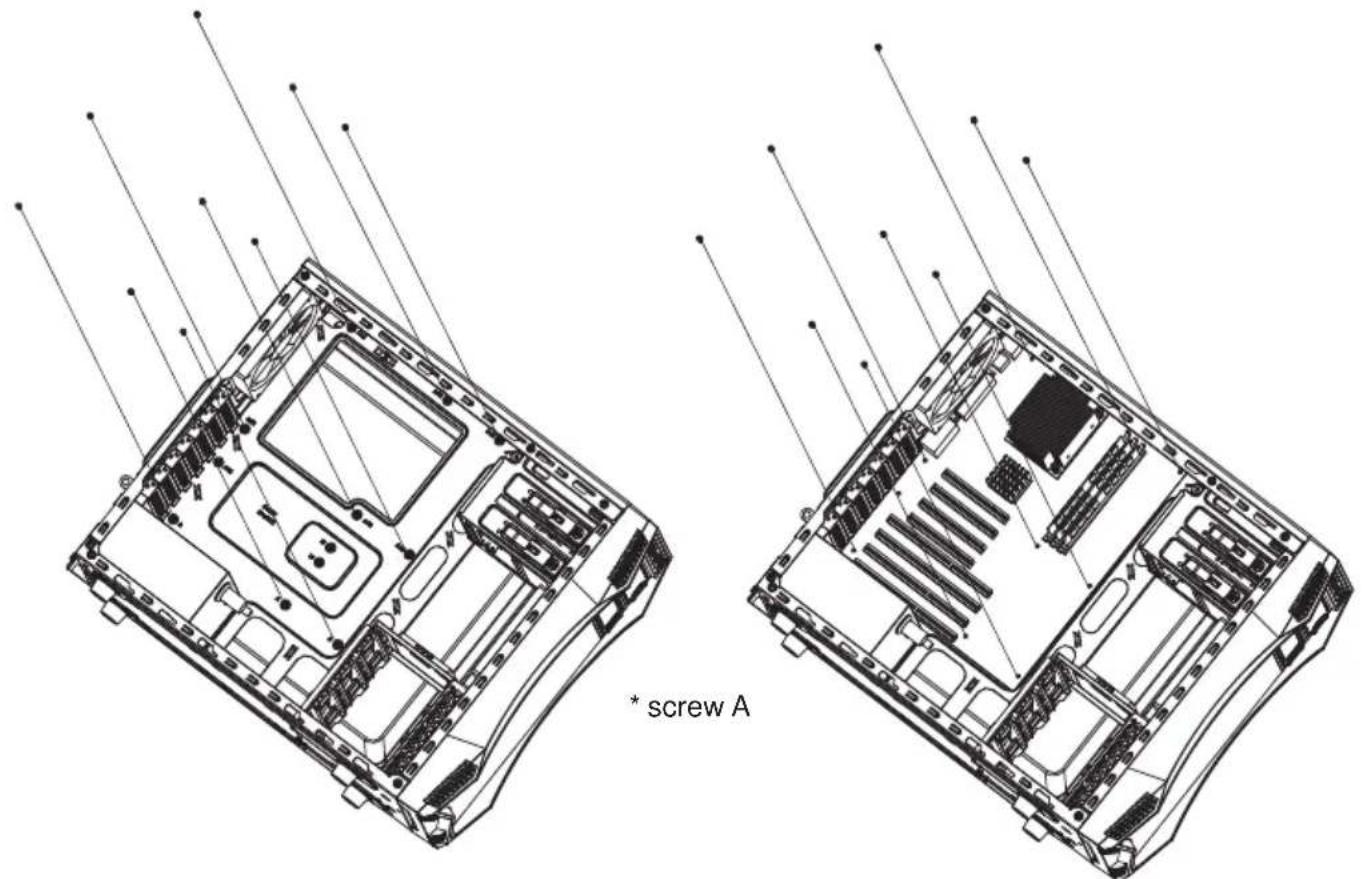
text_image
* screw A3-1 Place the motherboard standoffs based on manufacturer specs.
3-2 Secure the motherboard with screw-A.
natural_image
Technical diagram of an internal server rack with visible socket, drive, and ventilation slots (no text or labels)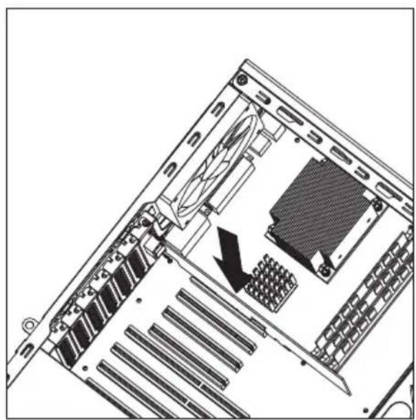
natural_image
Diagram of a computer tower rear panel showing internal components and a black arrow indicating a specific area (no text or symbols present)3-3 Unscrew to remove the slot cover. 3-4 Install the add-in card and secure with screws.
4. Install External 5.25" device
natural_image
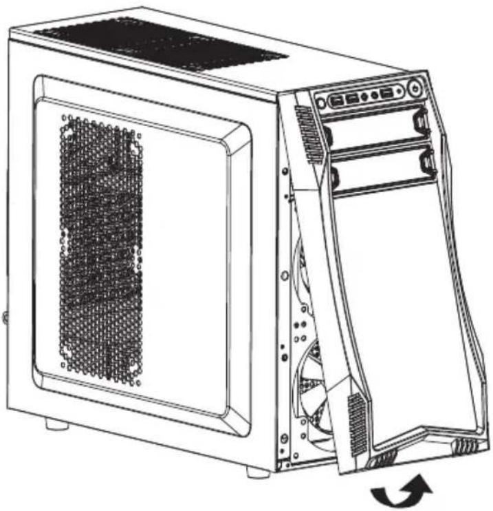
Line drawing of a desktop computer tower case with visible internal components and a circular arrow indicating rotation (no text or symbols)4-1 Pull outwards to remove the front panel.

natural_image
Technical line drawing of a computer tower case showing internal components and ventilation system (no text or labels)4-2 Remove the bay cover and insert the 5.25" drive into the bay until the latch clicks. Reinstall the front panel back onto the case.
5. Install 3.5"/2.5" HDD/SSD
natural_image
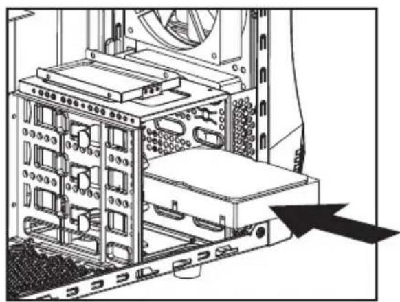
Technical diagram of a server rack with internal components and a black arrow pointing to a component (no text or symbols present)5-1 Insert the 3.5" HDD into the cage until the latch clicks.
natural_image
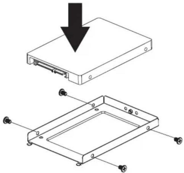
Technical diagram showing a device with a downward arrow and its 3D view of a rectangular frame with mounting holes (no text or symbols present)5-2 Remove the thumbscrew to retrieve the 2.5" bay.
5-3 Secure the 2.5" SSD/HDD with screw-A.
5-4 Install back with the thumbscrews.
6. System Ready
natural_image
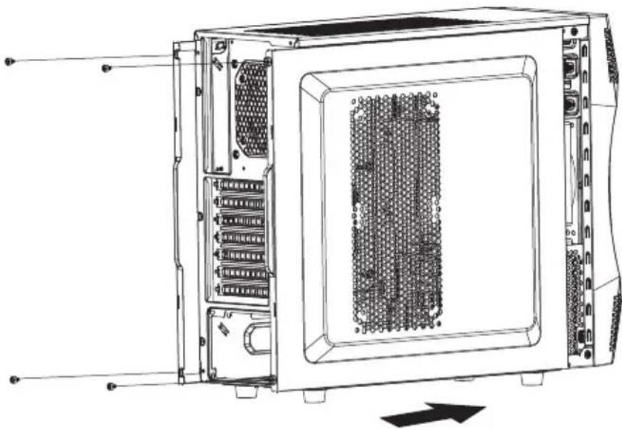
Technical line drawing of an internal server rack unit with visible ports and internal components (no text or labels)6-1 Slide the side panels back and secure with thumbscrews.
7. Clean the dust filters
7.1 Clean the dust filter regularly to ensure adequate airflow for power supply unit. (Unscrew to remove the top dust filter.)
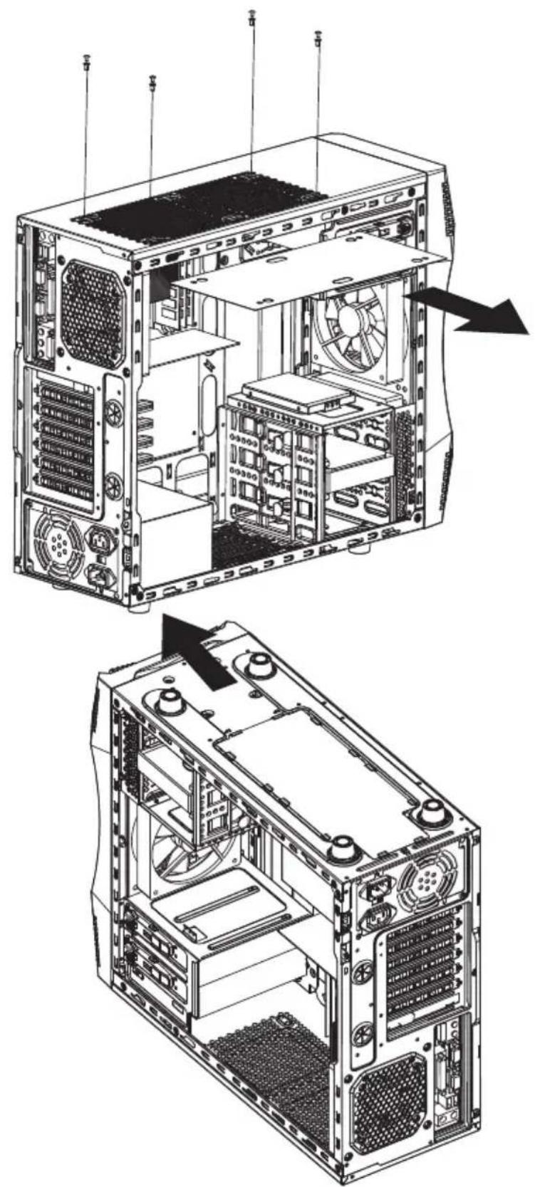
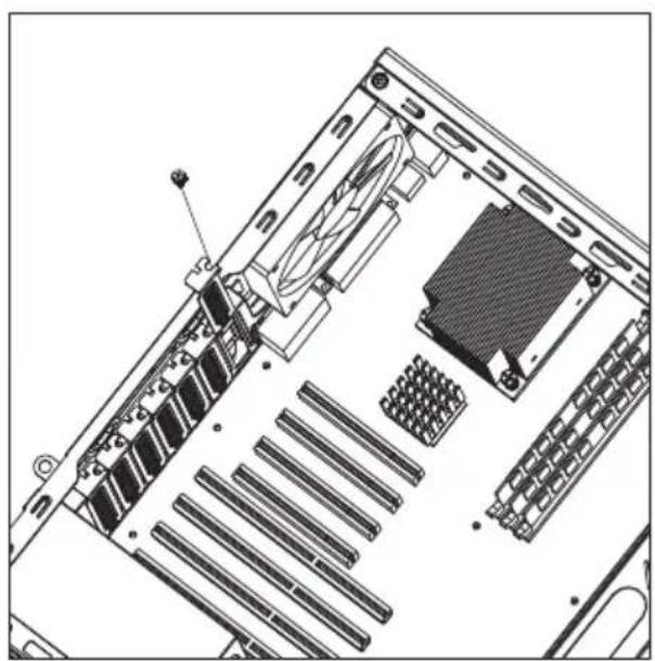
9. Optional: Additional Fan & Liquid Cooling Radiator
Challenger S has the capacity of installing additional fans :
a. 2x 120mm fans under top cover.
b. 2x 140mm fans on the side panel.
Insturation of installing 120mm water cooling radiator in the front :
a. Remove the front panel.
b. Unscrew to remove the 2.5" SSD/HDD tray on the bottom of the 5.25" cage.
c. Secure the radiator with screws and put the front panel back.
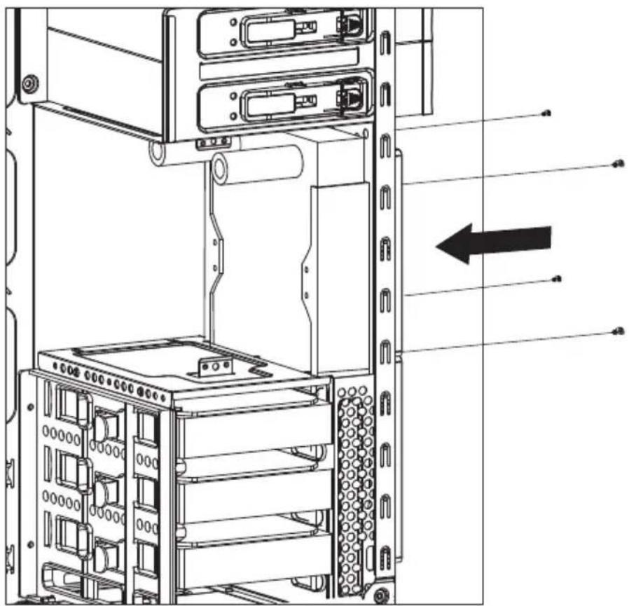
natural_image
Technical line drawing of a server rack with internal components and an arrow indicating direction (no text or symbols present)Rosewill®
www.rosewill.com