FB-04 - PC Case Rosewill - Free user manual and instructions
Find the device manual for free FB-04 Rosewill in PDF.

User questions about FB-04 Rosewill
0 question about this device. Answer the ones you know or ask your own.
Ask a new question about this device
Download the instructions for your PC Case in PDF format for free! Find your manual FB-04 - Rosewill and take your electronic device back in hand. On this page are published all the documents necessary for the use of your device. FB-04 by Rosewill.
USER MANUAL FB-04 Rosewill
natural_image
Line drawing of a desktop computer tower with indicator lights and a power button (no text or symbols)FB-03/04
User's Manual
Contents
■ Product Overview
Disassemble Chart P.2
Accessory Box P.3
■ Installation Guide
Opening Chassis P.4
Installing 2.5" HDD/SSD P.4
Installing Power Supply P.5
Installing Motherboard P.5
Installing Add-On Card P.6
Installing External 5.25"/3.5" Device P.7
Installing 3.5" HDD P.8
Closing Chassis P.9
■ Information P.9
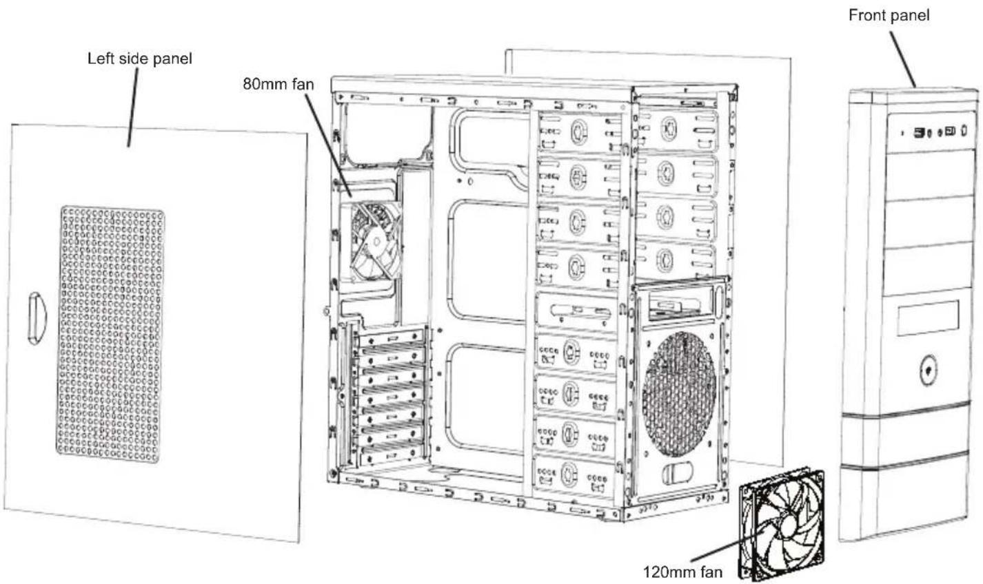
Disassemble Chart
( For reference only. Models' option may be varied by countries. )
text_image
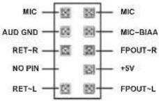
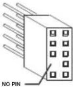
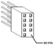
Left side panel 80mm fan Front panel 120mm fanFront I/O Pin Define
(Please refer to your motherboard's user's manual to connect.)
| HD CONNECTOR | AC97 CONNECTOR |
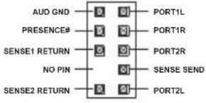  |   |
| USB2.0 CONNECTOR | |
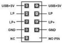  |
Accessory Box
 | 9 x M/B standoff Motherboard | |
 | 29 x screw-A | Motherboard5.25"/3.5" Device2.5" SSD/HDD |
 | 16 x screw-B 3.5" HDD | |
 | 11 x screw-C | Power SupplyAdd-on Card |
 | 1 x PC SPEAKER Motherboard | |
 | 5 x Cable tie Cables | |
 | 2 x PCI cover | Expansion Slot |
1. Opening Chassis
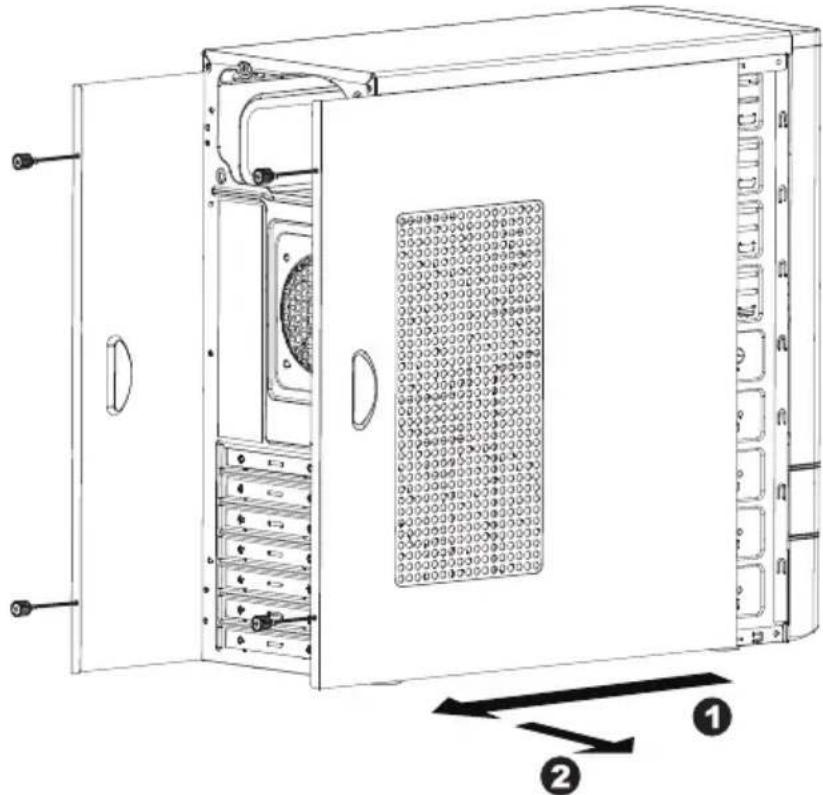
natural_image
Technical line drawing of an open industrial server unit with internal components and labeled parts (no text or symbols beyond labels)Unscrew to remove left and right panels.
2. Installing 2.5" HDD/SSD
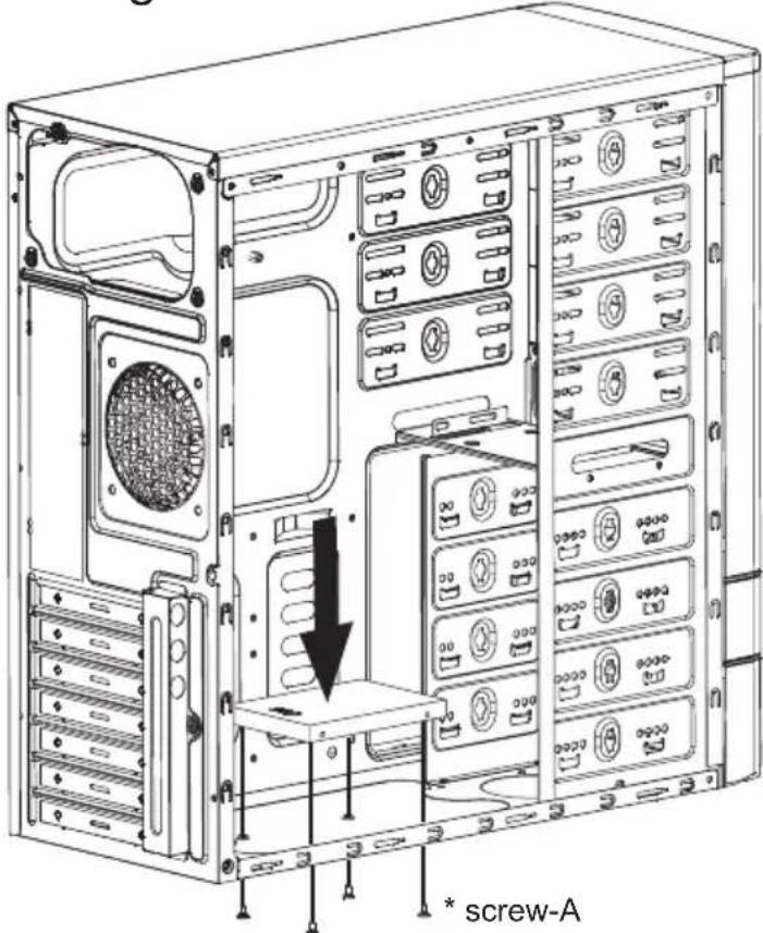
text_image
* screw-APlace 2.5" HDD/SSD onto the bottom of the chassis and secure with screws.
3. Installing Power Supply
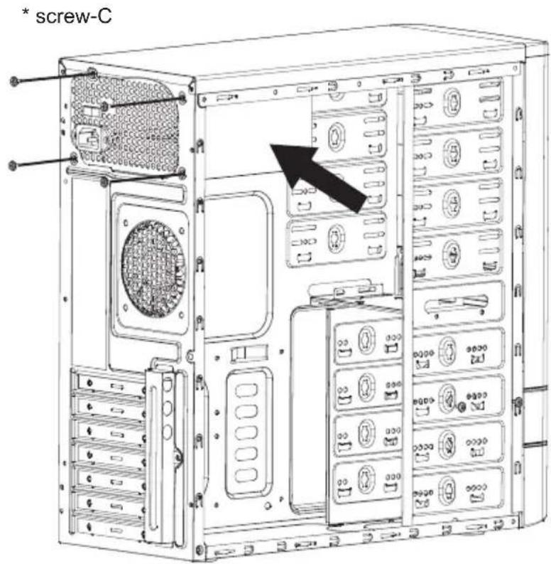
text_image
* screw-CPlace the power supply from the left side into the chassis and secure with screws.
NOTICE :
-If your power supply is equipped with single fan (120mm, 135mm or 140mm), please have the fan face to the bottom.
4. Installing Motherboard
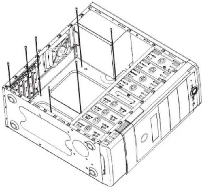
natural_image
Technical line drawing of a computer chassis with internal components and ventilation ducts (no text or symbols)Step 1- Install motherboard stand-offs according to your motherboard's form factor.
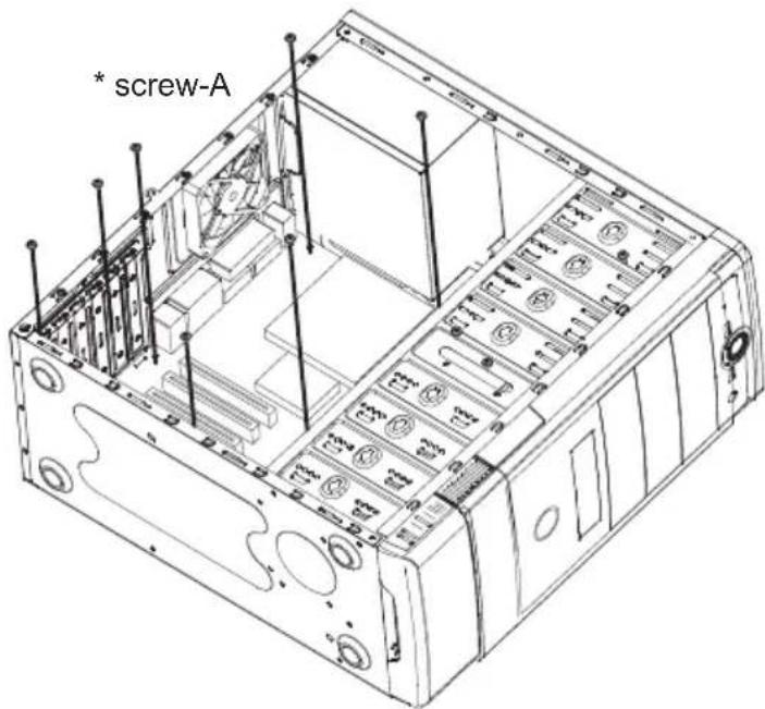
text_image
* screw-AStep 2- Place the motherboard onto stand-offs and secure with screws.
NOTE : NOT every motherboard is made by standard, please set stand-offs according to your motherboard.
5. Installing Add-On card

text_image
Step 1- Unscrew add-on Step 2- Release add-on Step 3- Remove PCI slotStep 1- Unscrew add-on card cover.
Step 2- Release add-on card cover.
Step 3- Remove PCI slot cover.
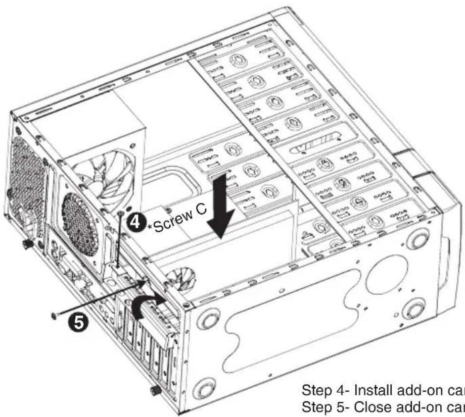
text_image
Step 4- Install add-on car Step 5- Close add-on carStep 4- Install add-on card and secure with screw.
Step 5- Close add-on card cover and secure with screw.
6. Installing External 5.25"/3.5" Device
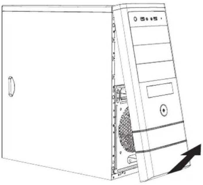
natural_image
Line drawing of a desktop computer tower with visible drive bays and ventilation slots (no text or labels)-Remove front panel by pulling from the bottom as shown.
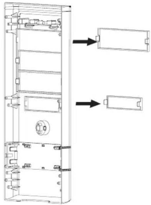
natural_image
Technical line drawing of a multi-chamber electronic device with internal components and mounting holes (no text or symbols)-Confirm which bay(s) you want to install device(s) then remove the bay cover.
7. Installing External 5.25"/3.5" Device
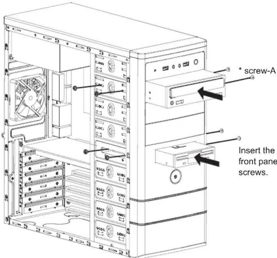
text_image
* screw-A Insert the front pane screws.Insert the external 5.25" & 3.5" device from the front panel into the chassis then secure with screws.
8. Installing 3.5" HDD
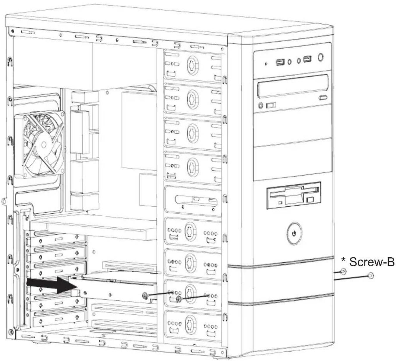
text_image
Screw-BPlace the 3.5" HDD into the HDD tray then secure with screws.
9. Closing Chassis
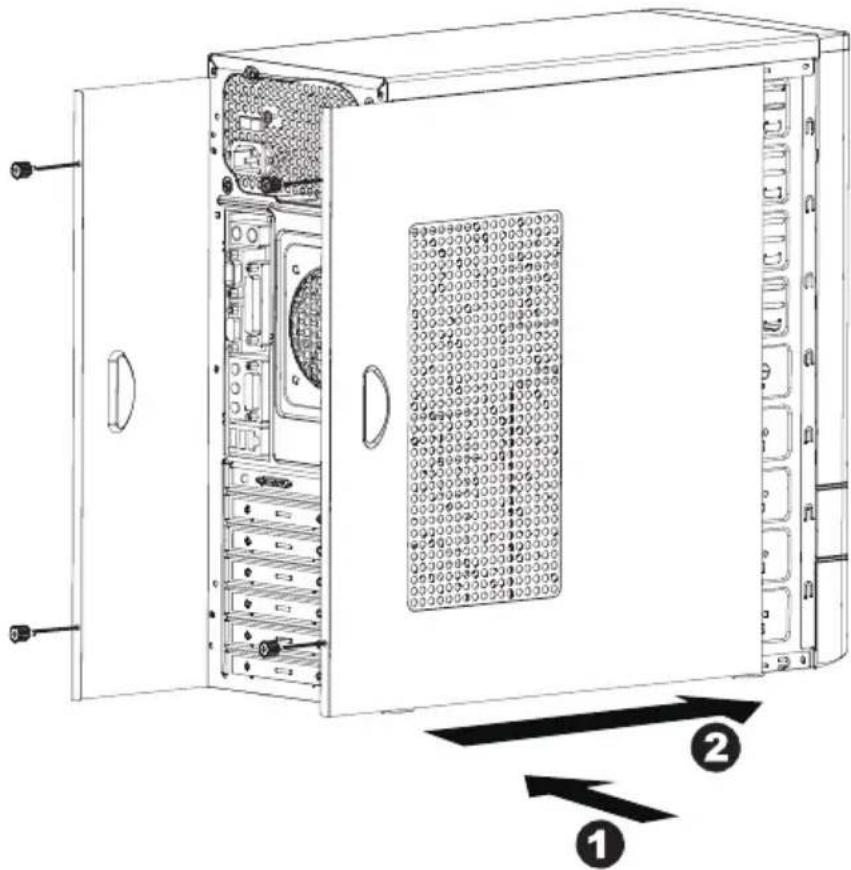
text_image
Technical diagram of a server rack cabinet with labeled components and directional arrows indicating assembly or movement.Make sure all necessary cables and wires are connected, then reinstall side panels and secure with screws.
Thank you for purchasing a High-Quality Rosewill Product.
Please register your product at : http://www.rosewill.com
for complete warranty information and future support for your product.
If you have any question while using our products, please visit our website: www.rosewill.com for latest driver & user manual or feel free to contact us.
Support Phone Number: 800-575-9885
Support Email: techsupport@rosewill.com