Semblance 15031 - Furniture BDI - Free user manual and instructions
Find the device manual for free Semblance 15031 BDI in PDF.

User questions about Semblance 15031 BDI
0 question about this device. Answer the ones you know or ask your own.
Ask a new question about this device
Download the instructions for your Furniture in PDF format for free! Find your manual Semblance 15031 - BDI and take your electronic device back in hand. On this page are published all the documents necessary for the use of your device. Semblance 15031 by BDI.
USER MANUAL Semblance 15031 BDI
natural_image
Abstract geometric design with overlapping orange and black squares (no text or symbols)SEMBLANCE
MODULAR SYSTEM
MAIN
ASSEMBLY
INSTRUCTIONS
To view the Semblance assembly video, scan this code with a QR reader or visit http://www.bdiusa.com/semblance/assembly.shtml

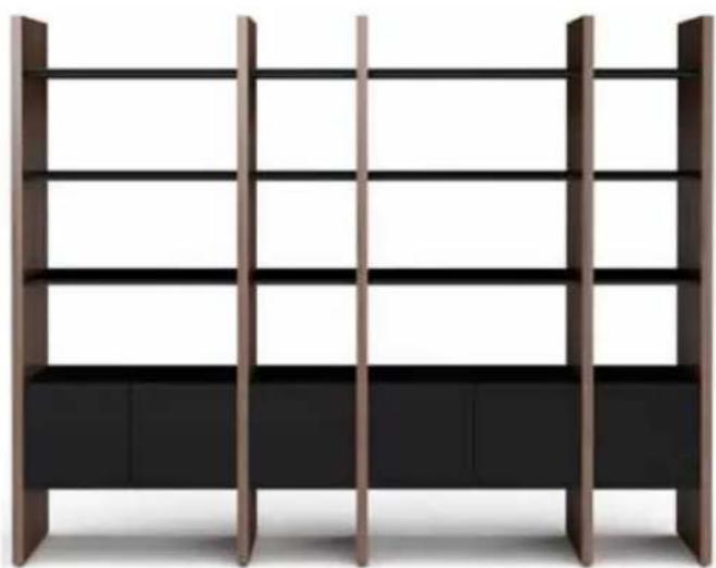
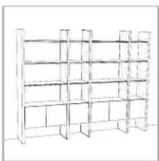
natural_image
Modern wooden bookshelf with vertical shelves and black cabinet (no text or symbols visible)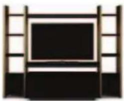
natural_image
Simple illustration of a TV setup with a black monitor and wooden shelves (no text or symbols)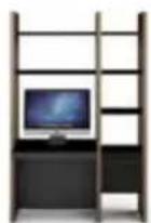
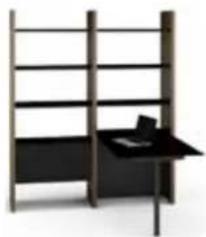
natural_image
Modern minimalist furniture layout with vertical shelving and a black desk (no text or symbols)
natural_image
Modern office setup with bookshelf, desk, and monitor (no text or symbols visible)BDi

TWO PERSON ASSEMBLY
Semblance System
Your SEMBLANCE System Furniture is engineered for easy assembly. Carefully follow this procedure to prevent any damage.
Placement and
Maintenance
SEMBLANCE System Furniture is designed for indoor use on level floors. Clean glass with glass cleaner, steel parts and wood veneer with a moist cloth.

You will need:

natural_image
Simple line drawing of a pencil with eraser (no text or symbols)
natural_image
Line drawing of a mechanical measuring tool with a cylindrical head and handle (no text or symbols)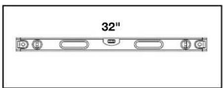
text_image
32"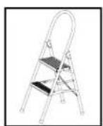
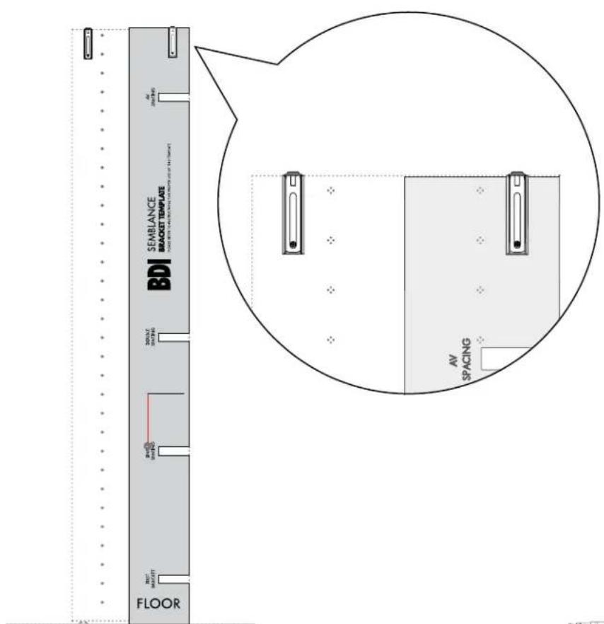
Semblance Wall Bracket Template

natural_image
Two stylized human figures standing side by side, no text or symbols presentThis Template helps locate the various positions of the second Wall Bracket.
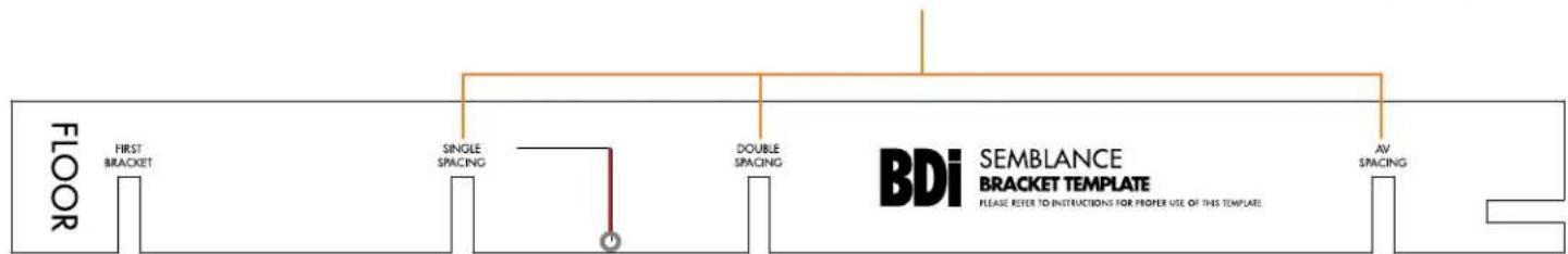
flowchart
graph LR
    A["FLOOR"] --> B["FIRST BRACKET"]
    B --> C["SINGLE SPACING"]
    C --> D["DOUBLE SPACING"]
    D --> E["AV SPACING"]
    style A fill:#f9f,stroke:#333
    style B fill:#ccf,stroke:#333
    style C fill:#cfc,stroke:#333
    style D fill:#fcc,stroke:#333
    style E fill:#cff,stroke:#333
    subgraph BDi SEMBLANCE BRACKET TEMPLATE
        direction TB
        B1["O"]
        B2["O"]
        B3["O"]
    end
    note right of BDi SEMBLANCE BRACKET TEMPLATE
    note right of BDi SEMBLANCE BRACKET TEMPLATE
    note right of BDi SEMBLANCE BRACKET TEMPLATE
    note right of BDi SEMBLANCE BRACKET TEMPLATE
    note right of BDi SEMBLANCE BRACKET TEMPLATE
    note right of BDi SEMBLANCE BRACKET TEMPLATE
    note right of BDi SEMBLANCE BRACKET TEMPLATE
    note right of BDi SEMBLANCE BRACKET TEMPLATE
    note right of BDi SEMBLEBRACKET TEMPLATE
    note right of BDi SEMBLEBRACKET TEMPLATE
    note right of BDi SEMBLEBRACKET TEMPLATE
    note right of BDi SEMBLEBRACKET TEMPLATE
    note right of BDi SEMBLEBRACKET TEMPLATE
    note right of BDi SEMBLEBRACKET TEMPLATE
    note right of BDi SEMBLEBRACKET TEMPLATE
    note right of BDi SEMBLEBRACKET TEMPLATE
    note right of BDi SEMBLEBRACKET TEMPLATE

text_image
SINGLE SPACING This is a leveling string to level the placement of your Wall Brackets.Locate the Package Reference Booklet
See page 2 to identify all components. For missing hardware pieces, please contact BDI Customer Service at customerservice@bdiusa.com. For all other concerns, please contact your BDI Retailer.
See page 3 for a representation of your Package containing critical information for its assembly.
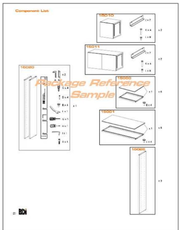
text_image
Component List 18010 x2 1 x 2 K x 4 L x 8 15011 x2 1 x 7 K x 4 L x 8 15000 x1 Ex 4 1 x 3 U x 1 H x 1 I x 1 X x 4 15001 x1 Ex 4 15006 x3 Package Reference Sample 2 BDI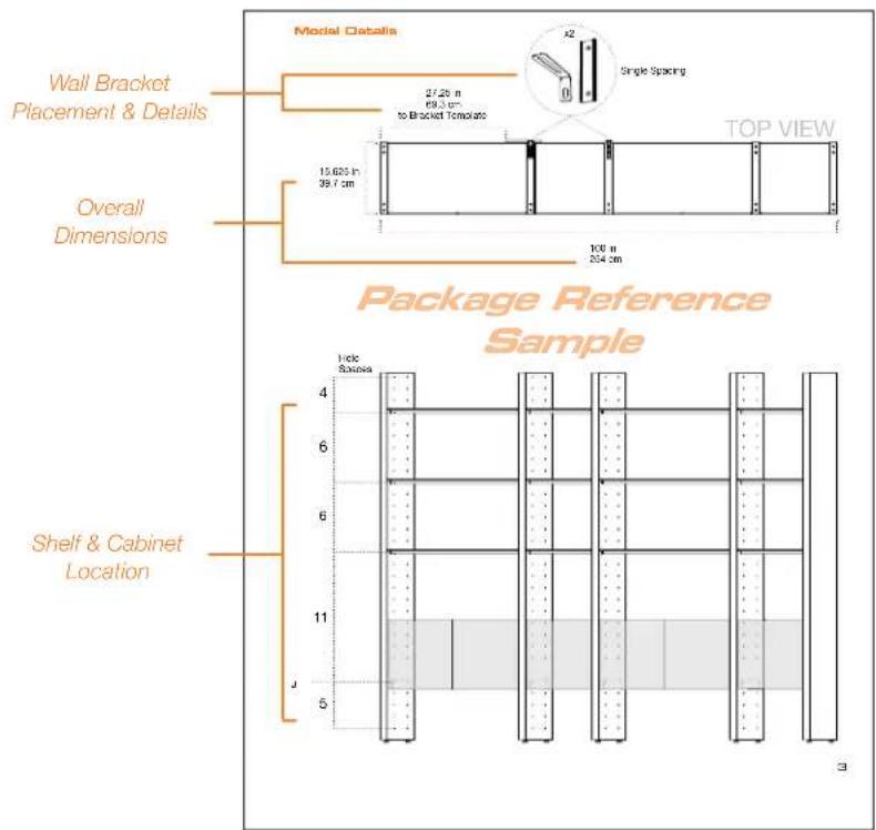
text_image
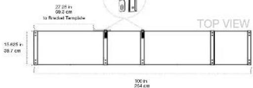
Wall Bracket Placement & Details Overall Dimensions Package Reference Sample Model Details 27.25 m 69.3 cm to Bracket Template 15.625 in 39.7 cm 100 n 254 cm TOP VIEW 1 side Sousa Shelf & Cabinet LocationWALL SYSTEM
PAGE 4
natural_image
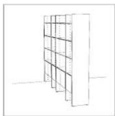
Line drawing of a multi-level shelving unit with no text or symbolsROOM DIVIDER
PAGE 10
natural_image
Simple line drawing of a cabinet or storage unit with shelves and doors, no text or symbols presentSHELF ASSEMBLY
PAGE 14

natural_image
Pure architectural floor plan lines without any text, numbers, or symbolsCABINET ASSEMBLY
PAGE 17
natural_image
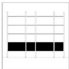
Grid pattern with alternating white and black rectangular blocks (no text or symbols)WALL SYSTEM
Assembly Sequence Overview
natural_image
Technical line drawing of a vertical metal door with mounting brackets and structural details (no text or symbols)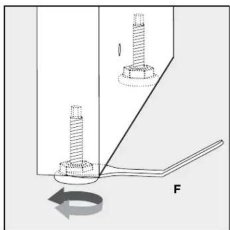
natural_image
Mechanical diagram showing two bolts inserted into a housing with a force arrow indicating rotational motion (no text or symbols)Level each Panel as it is being assembled. Use Leveler Wrench (F) to adjust the height of the Panel, if necessary.
Plan Ahead.
To plan unit placement, refer to Package Reference Booklet for critical dimensions.

The assembled unit CANNOT be moved, so carefully plan the placement of the unit prior to building.
natural_image
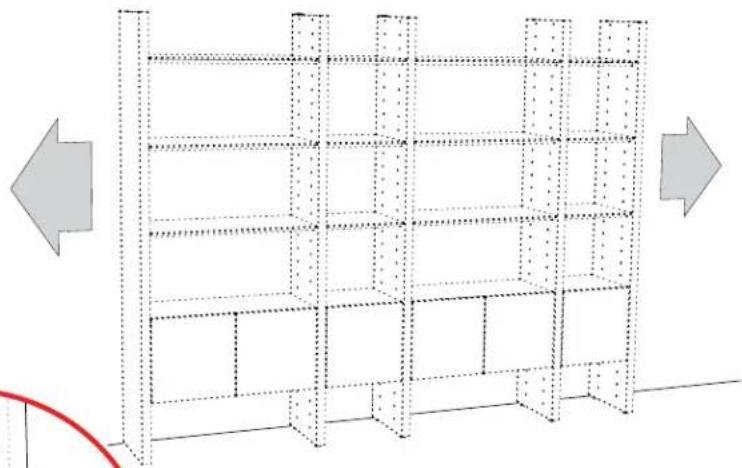
Diagram of a multi-level storage or warehouse unit structure with directional arrows indicating orientation (no text or symbols)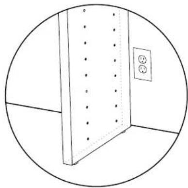
natural_image
Simple line drawing of a room corner with a vertical panel and electrical outlet (no text or symbols)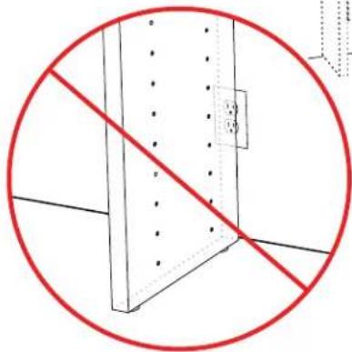
natural_image
Pure diagram of a structural beam with no text, numbers, or symbols, showing a red prohibition symbol (no text or labels)1:
See the Bracket Template spacing dimension on page 3 of the Package Reference Booklet. Using the provided spacing dimension, measure from the edge of where the left End Panel will be placed and mark the wall to indicate placement of the bracket template.

text_image
Note: Future placement of left End Panel TOP VIEW Package Reference Sample2:
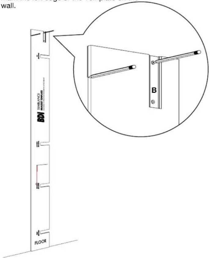
Align the left side of the Bracket Template with the wall mark. Level the Template with the string, and insert Wall Bracket (B) into its designated groove. Mark the wall at bracket holes to locate fastener locations.

text_image
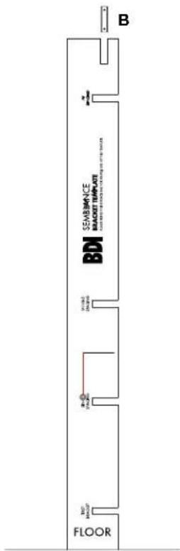
B I the art d holes BDI SEMBLANCE BRACKET TEMPLATE 300#E 140#E BDI BET BRACKET FLOOR3:

text_image
SEMBLANCE BRACKET TEMPLATE BDI FLOOR B4:
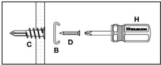
Attach first Bracket to the wall using the appropriate attachment method illustrated below.
text_image
C B D H MOLUBA.COMSheet Rock: (C) Drywall Anchors
(B) Bracket
(D) Screws
text_image
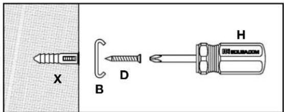
X B D HConcrete/Brick: (X) Plastic Concrete Anchors
(B) Bracket
(D) Screws
A 14 " masonry drill bit and Power Drill is required for pilot holes.

text_image
B D H ROUBACOMWooden Beam: (B) Bracket
(D) Screws
5:
Refer to Package Reference Booklet for the number of recommended Wall Brackets.
If 1 Bracket, skip to step 9 on page 8.
If 2 Brackets, proceed to step 6 and finish the Wall System section of the instructions.
6:
Use the Bracket spacing groove that is determined by your Package Reference Booklet (2 of 2), to locate the second Bracket.
Model Details
text_image
27.25 in 69.3 cm to Radial Template 15.625 in 39.7 cm TOP VIEW 100 in 254 cm
text_image
J Spaces 4 6 6 11 5
text_image
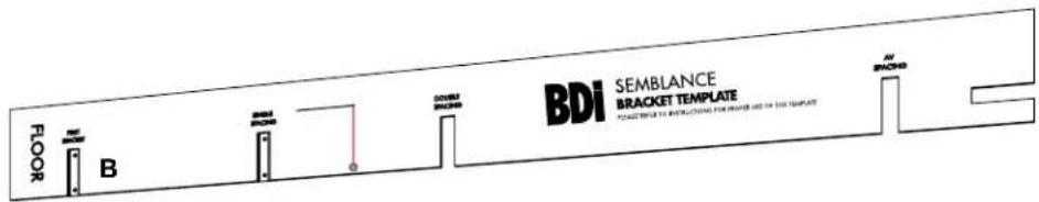
BDI SEMBLANCE BRACKET TEMPLATE7:
Slip the Template over the attached Bracket (B). Level the Template with the string and mark second Bracket hole locations on wall.
text_image
FLOOR B BDI SEMBLANCE BRACKET TEMPLATE FOR EACH 100% FOR INTRODUCTION FOR ORDER USED TO THE TEMPLATE AV BRANCH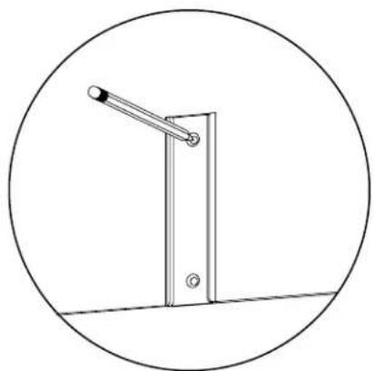
natural_image
Simple line drawing of a vertical pole with a lever, enclosed in a circle (no text or symbols)8:
Refer to Step 4 on page 6 to attach second Bracket (B)
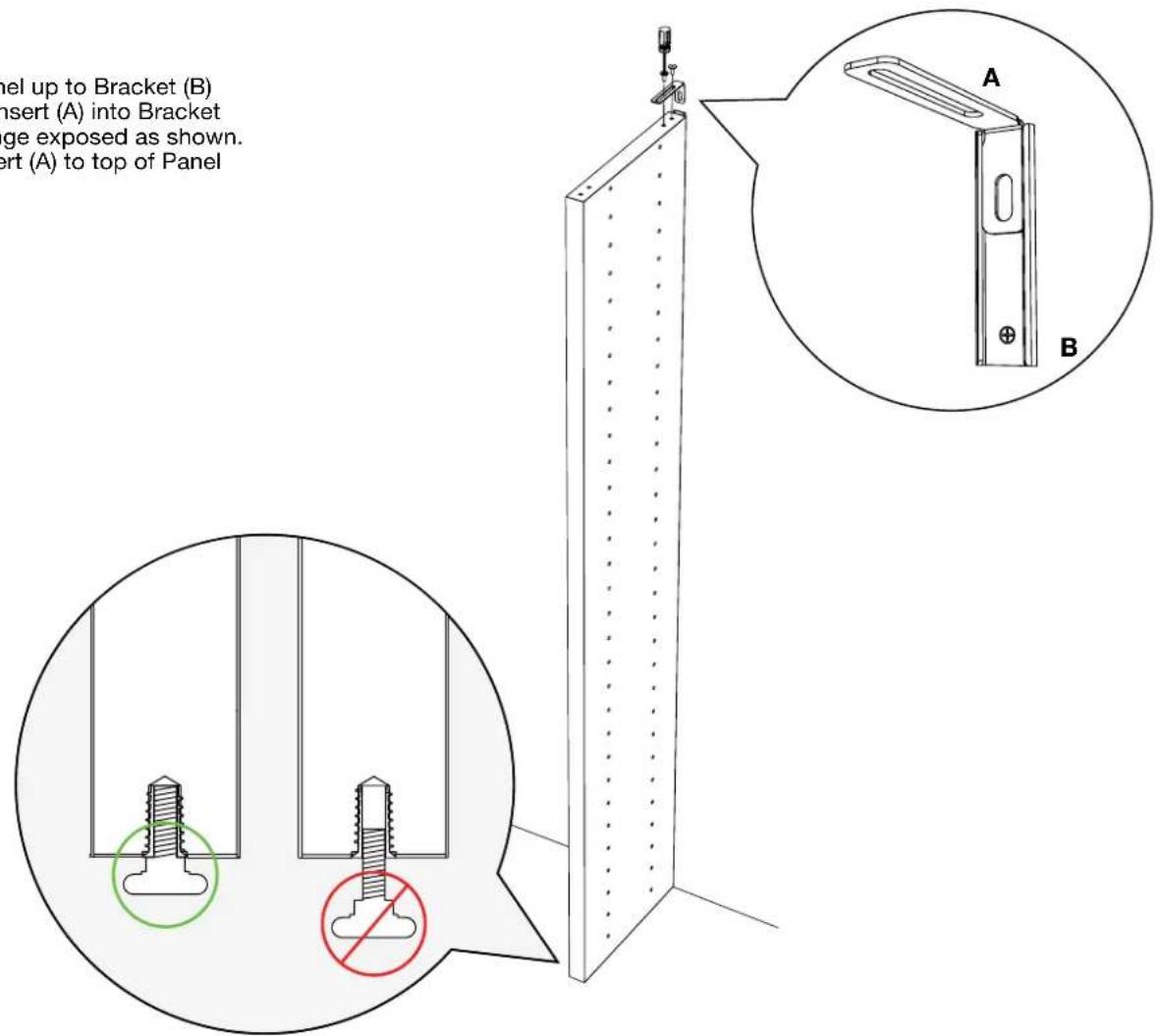
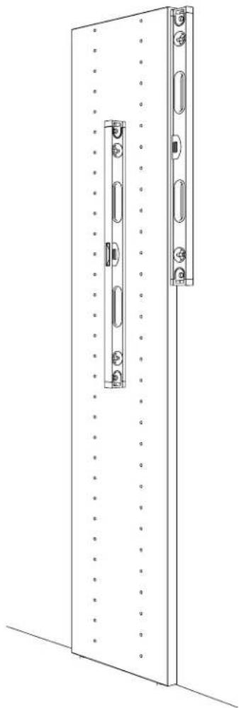
Bring Divider Panel up to Bracket (B) and slide Metal Insert (A) into Bracket with the long flange exposed as shown. Attach Metal Insert (A) to top of Panel with Screws (E).
9:
text_image
Panel up to Bracket (B) insert (A) into Bracket ge exposed as shown. ert (A) to top of Panel10:
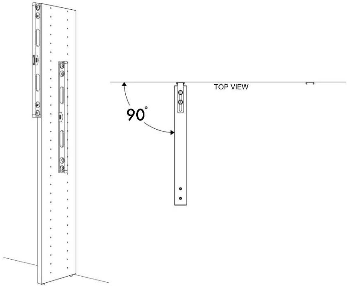
text_image
TOP VIEW 90°For next step turn to SHELF ASSEMBLY PAGE 14

natural_image
Pure architectural floor plan lines without any text, numbers, or symbolsROOM DIVIDER
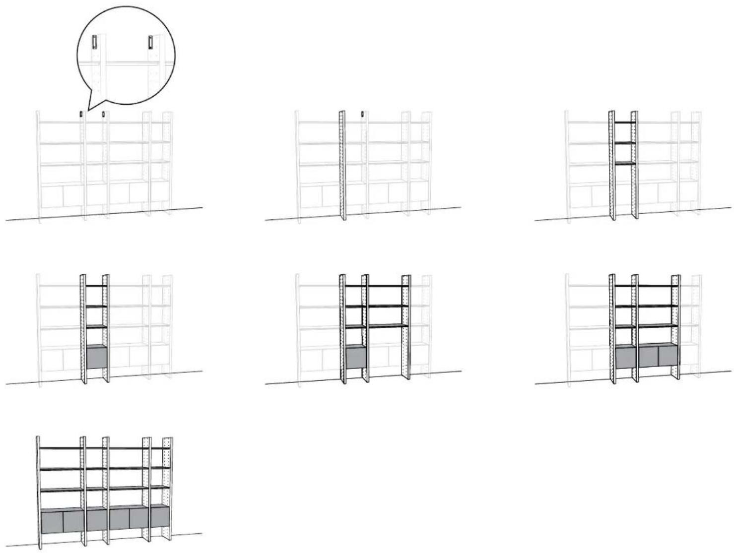
Assembly Sequence Overview

natural_image
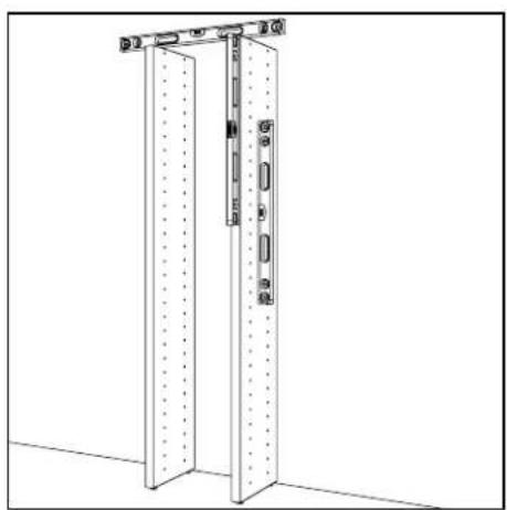
Technical line drawing of a vertical metal door with mounting brackets and a wall-mounted bracket (no text or symbols)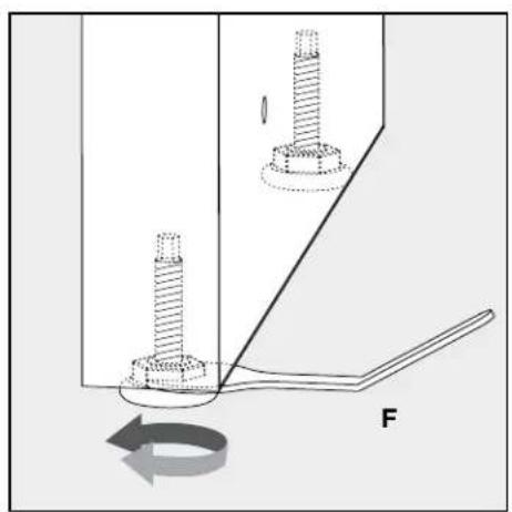
natural_image
Mechanical diagram showing two bolts inserted into a housing with a rotating arrow indicating rotation (no text or symbols)Level each Panel as it is being assembled. Use Leveler Wrench (F) to adjust the height of the Panel, if necessary.
Plan Ahead.
To plan unit placement, refer to Package Reference Booklet for critical dimensions.

The assembled unit CANNOT be moved, so carefully plan the placement of the unit prior to building.

natural_image
Simple line drawing of a cabinet with vertical holes and an electrical outlet (no text or symbols)
natural_image
Simple line drawing of a cabinet with a diagonal red prohibition symbol (no text or labels)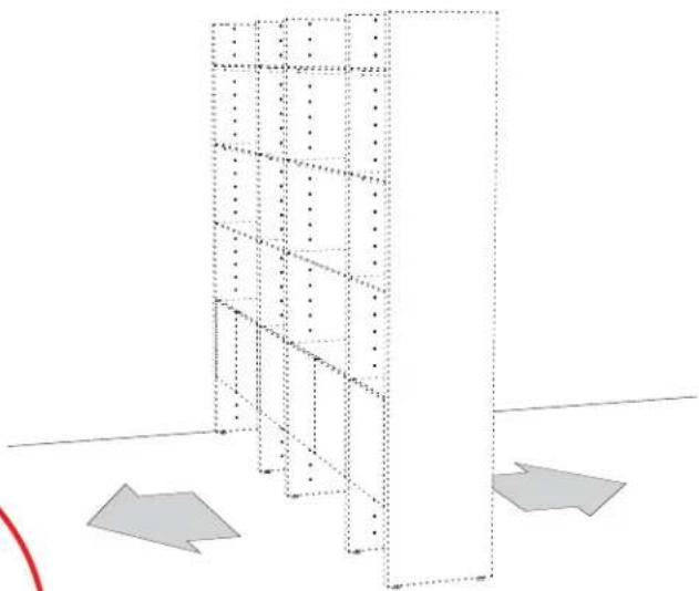
natural_image
3D architectural diagram showing a vertical shelving unit with multiple tiers and two gray directional arrows indicating orientation (no text or symbols)1:
Use the right edge of the Bracket Template to locate the right side of the attached End Panel.
text_image
SEMBLANCE BRACKET TEMPLATE BDI FLOOR AV SPACING2:
Leveling the Template with the string, insert Wall Bracket (B) into designated groove.
text_image
B SEMBANCE BRACKET THAPLOT FLOOR3:
Mark Bracket hole location on wall and mark the left edge of the Template on the wall.
text_image
wall. SEAVANCE BDO FLOOR B4:
Flip Template over and align right side of Template with wall mark to locate second Bracket position. Mark second Bracket hole location lightly on wall and then install Bracket.

text_image
all BDI BDL BDL BDL BDL BDL BDL BDL BDL BDL BDL BDL BDL BDL BDL BDL BDL BDL BDL BDL BDL BDL BDL BDL BDL BDL BDL BDL BDL BDL BDL BDL BDL BDL BDL5:
Refer to Step 4 on page 6 to attach both Brackets.
6:
Bring End Panel up to attached Bracket (B) and slide Metal Insert (A) into Bracket (B) with the short flange exposed as shown. Attach Metal Insert (A) to top of Panel with Screws (E).

text_image
with both Bracket Bracket as top of A B E G A B7:
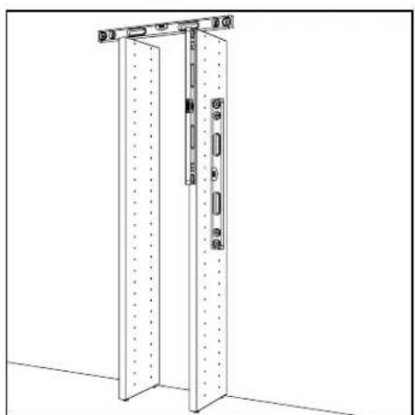
natural_image
Technical line drawing of a door frame with mounting holes and a vertical lock mechanism (no text or symbols)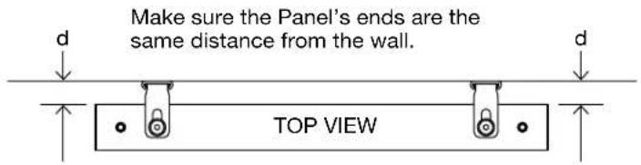
text_image
Make sure the Panel's ends are the same distance from the wall. TOP VIEWSHELF ASSEMBLY
1:
Refer to Package Reference Booklet for the hole positions of the Shelf Screws (E).
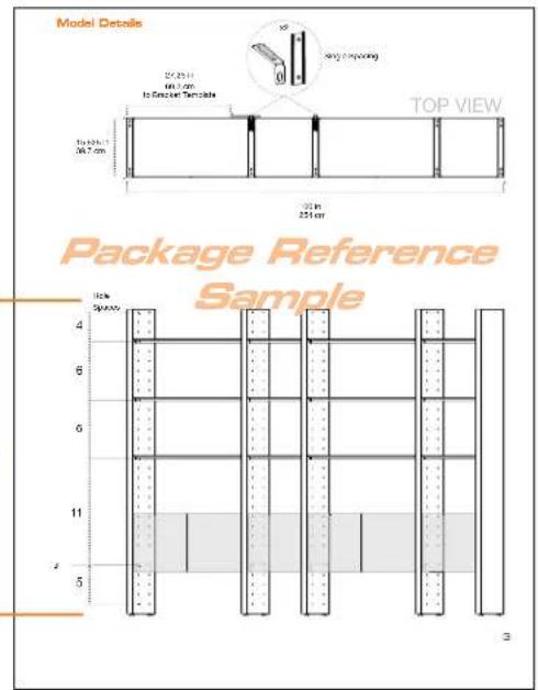
text_image
Model Details 25/25/11 60.3 cm to Screen Template 10x 40x 7 36.7 cm 20 in 251 cm TOP VIEW Package Reference Sample 10x Spacey 4 6 6 11 5 32:

text_image
Technical diagram showing a mechanical assembly with labeled components E and I, including a magnified view of the component.
text_image
PANEL SHELF PANEL SHELF3:
Use the appropriately sized Shelf Frame as a spacing guide for the next Panel. Lay the Frame on the floor beside the fixed Panel and bring the next Panel up to the Shelf Frame.
Refer to the Package Reference Booklet for spacing of each set of Panels.

natural_image
Diagram of a vertical structure with a horizontal beam and an arrow indicating rotation or force direction (no text or symbols)4:

natural_image
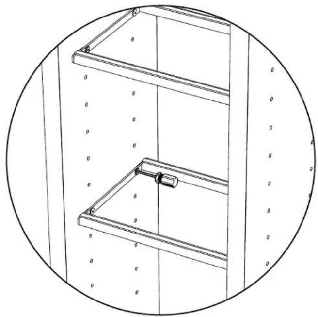
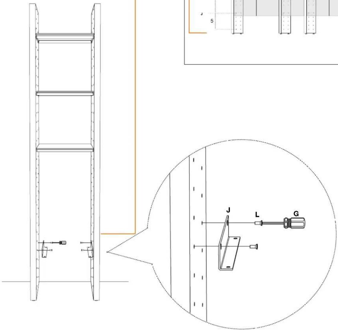
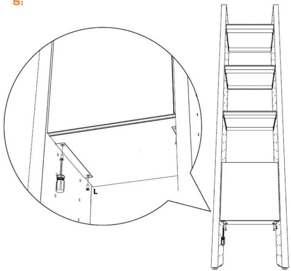
Technical line drawing of a ladder structure with an inset magnified view showing a bracket and mounting holes (no text or symbols)5:
Slide Metal Insert (A) into attached Bracket (B) with the long flange exposed as shown. Attach Metal Insert (A) to top of Panel with Screws (E).

natural_image
Technical line drawing of a multi-tiered shelving unit with an inset showing a close-up view of the component (no text or symbols present)6:
Gently tighten all Shelf Frames.
natural_image
Technical line drawing of a multi-level shelving unit with no visible text or symbols7:
Install Glass Shelves.
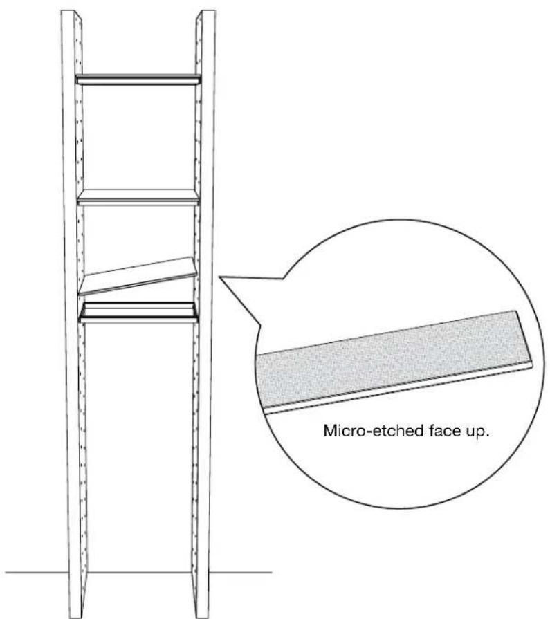
text_image
Micro-etched face up.CABINET ASSEMBLY
1:
Refer to Package Reference Booklet for Cabinet Bracket positions.
2:
Screw Cabinet Brackets (J) into determined inserts.
text_image
Technical diagram showing a ladder assembly with labeled components and a magnified view of the lever mechanism.Model Details

text_image
Model Details 27.25 in 69.3 cm to Bracket Template 15.625 in 39.7 cm x2 Single Spacing TOP VIEW 100 in 254 cmPackage Reference
Sample
text_image
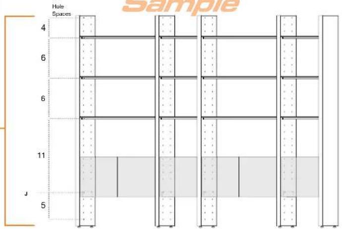
Hole Spaces 4 6 6 11 J 5 Sample3:
Slide Cabinet in between panels, well above the Bracket, and carefully lower into place so that Cabinet Bracket fits into the recess on cabinet's bottom side.

text_image
between panels, well and carefully lower into set Bracket fits into the s bottom side.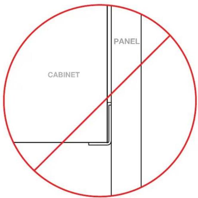
text_image
CABINET PANEL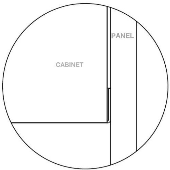
text_image
PANEL CABINET4:

natural_image
Technical line drawing of a cabinet with open door and internal components, showing exterior and front views (no text or symbols)5:
natural_image
Technical line drawing of a ladder assembly with an inset circular detail showing internal components (no text or symbols)After completing the assembly of Bracketed Panels, repeat Shelf and Cabinet Assembly for each consecutive Panel until your Package is complete.

text_image
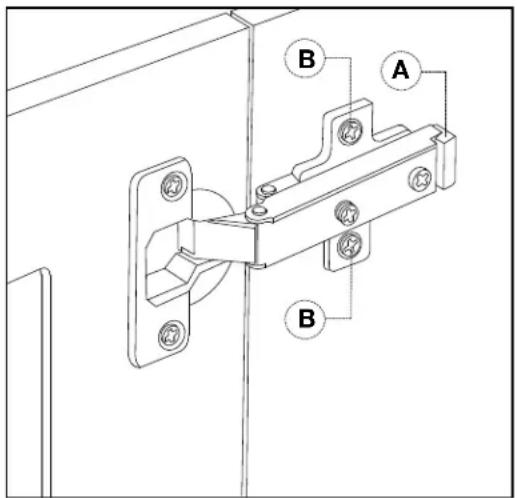
Technical diagram of a door latch mechanism with numbered components and directional arrows indicating movement or assembly.ADJUST DOOR HINGES (IF NEEDED)
If the cabinet's door appears out of alignment, this can be corrected with minor adjustment on each door.
Because these hinges are infinitely adjustable, adjusting one hinge element can sometimes cause the need for adjustments to other elements. But with a few adjustments, you can modify the orientation of the cabinet door to make sure that it hangs evenly.
Use a Phillips screwdriver to adjust cabinet's door hinges:
- By adjusting Screw 1, the door will move LEFT or RIGHT within the frame. Make minor adjustments at both top and bottom hinges for best results.
- By adjusting Screw(s) 2, the door will move UP or DOWN within the frame (the top and bottom hinges must be adjusted the same degree).
NOTE: Loosen Screws 2 one complete turn, raise or lower door, then hold in position while tightening Screws 2 (on both hinges).
- By adjusting Screw 3 the entire door will move IN or OUT, opening or closing the gap between the doorframe and cabinet. (This screw rarely needs adjustment.)
text_image
A B BREVERSE DOOR-SWING (IF DESIRED)
The Single Cabinets feature a reversible door assembly so that you can open either from the left or the right.
To reverse the door's orientation,
- Remove the Door by actuating both of its quick-release hinges (A); carefully place the detached Door aside.
- Using a Philips head screwdriver, remove both Hinge Plates from the interior wall of the cabinet by loosening the screws holding it in place (B).
- Install both Hinge Plates to the opposite interior wall at the pre-determined locations.
- Re-install the Door by connecting each Door Hinge to the relocated Hinge Plates.
Helpful Tips for Designing your own Semblance Package.
text_image
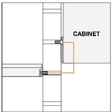
CABINETThe Cabinet Bracket Screw must be 1 space hole above the Shelf Screw to align Cabinet bottom with the top of a Shelf.
text_image
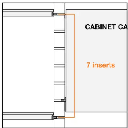
CABINET CA 7 insertsThere is a 7 insert spacing pattern to align Shelves with top and bottom of a Cabinet.

text_image
3 insertsThere is a 3 insert spacing pattern, from Cabinet Bracket to Shelf Frame, to align Shelves with middle of a Cabinet.