TH-VWP-160 - Support de panneau mural Atdec - Free user manual and instructions
Find the device manual for free TH-VWP-160 Atdec in PDF.

User questions about TH-VWP-160 Atdec
0 question about this device. Answer the ones you know or ask your own.
Ask a new question about this device
Download the instructions for your Support de panneau mural in PDF format for free! Find your manual TH-VWP-160 - Atdec and take your electronic device back in hand. On this page are published all the documents necessary for the use of your device. TH-VWP-160 by Atdec.
USER MANUAL TH-VWP-160 Atdec
- Power Drill
- 8mm (0.31") Drill Bit
• 10mm (0.39") Masonry Drill Bit - 13mm (0.51") Socket Wrench Shifter
• Phillips Head Screwdriver - Spirit Level
- Tape Measure
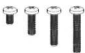
M8 × 16/30/50/65
(x4)

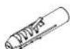
Spacer (x8)
Wall Plate 1.6m
(TH-VWP-160)
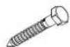
Coach Screw (x3)
Nylon
Anchor (x3)

8mm Washer (x3)
IMPORTANT INFORMATION:
! IMPORTANT - Install Video Wall as per installation instruction.
! This product supports a maximum load of 165kg (363lbs.) per panel or screen.
! The manufacturer accepts no responsibility for incorrect installation.
Step 1. Check Components
Check you have received all parts against the component checklist and hardware on the previous page.
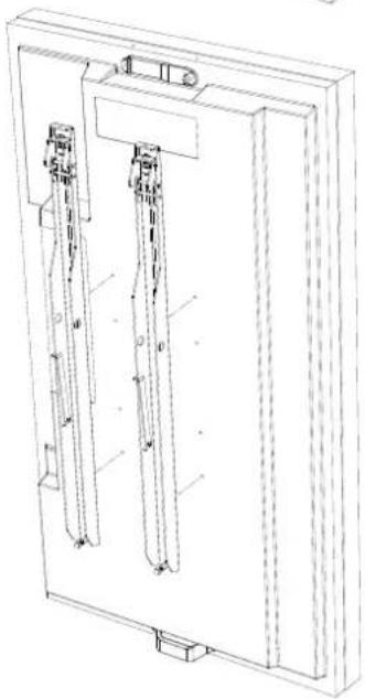
Step 2. Mounting Brackets

natural_image
Technical line drawing of a rectangular frame with two vertical supports and mounting brackets (no text or symbols)Option A
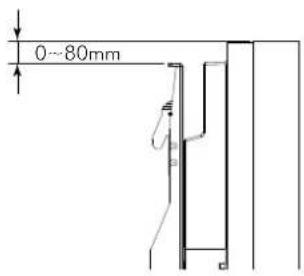
If the distance between the top of the display & mounting bracket is 80mm and under, mount directly onto the screen.
text_image
0~80mmIMPORTANT
For the Brackets to function correctly they must be mounted as close to the top of the screen as possible.
When mounting multiple screens the brackets must be mounted in exactly the same position each time to ensure alignment.
natural_image
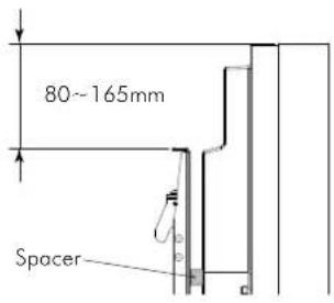
Technical line drawing of a mechanical assembly with two vertical components and mounting brackets (no text or symbols)Option B
If the distance between the top of the display & mounting bracket is between 80 and 165mm, mount using spacers included.
text_image
80~165mm SpacerNOTE: The top of the bracket must not be higher than the top of the screen.
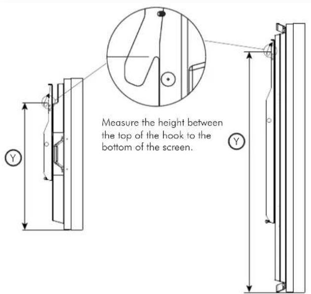
Step 3. Mounting first Wall Plate
3.1. 3.2.

natural_image
Two rectangular objects with arrows pointing to each other, no text or symbols presentDetermine the desired height of your screen from the floor.
text_image
Measure the height between the top of the hook to the bottom of the screen.3.3.
text_image
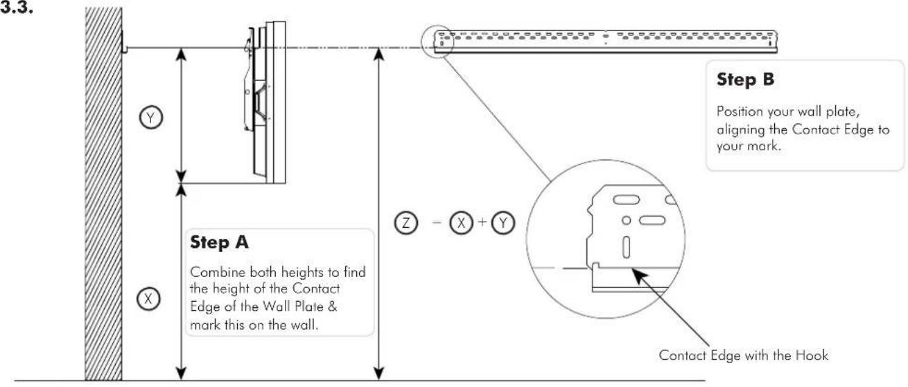
3.3. Step A Combine both heights to find the height of the Contact Edge of the Wall Plate & mark this on the wall. Step B Position your wall plate, aligning the Contact Edge to your mark. Contact Edge with the Hook3.4.
Please use a Spirit Level during installation to ensure that the Wall Plate is LEVEL

natural_image
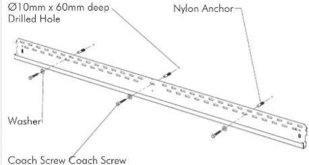
Pure electrical circuit lines without any symbols2 coach screws are provided for the TH-VWP-050, TH-VWP-080, TH-VWP-100 and 3 coach screws are provided for the TH-VWP-160. Ensure all screws are used with exception of where timber studs are spaced too far apart.
Masonry Timber Stud
text_image
Ø10mm x 60mm deep Drilled Hole Nylon Anchor Washer Coach Screw Coach Screw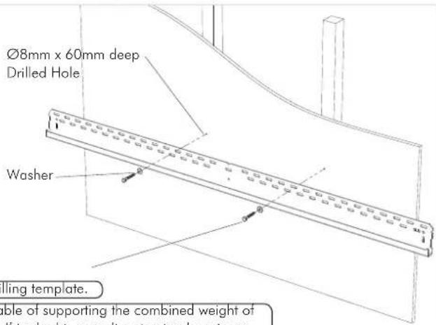
text_image
Ø8mm x 60mm deep Drilled Hole Washer Rolling template. able of supporting the combined weight of flis double, resulting structural designers.TIP: Use Mount as a drilling template.
IMPORTANT! Any structural elements must be capable of supporting the combined weight of all the equipment and devices being mounted. If in doubt, consult a structural engineer.
Step 4. Mount remaining Wall Plates
4.1.
Repeat Step 3.4 with the following to install the remaining Wall Plates
Please use a Spirit Level during installation to ensure that the Wall Plates are LEVEL

text_image
0 0 1:1 Match Profiles4.2.
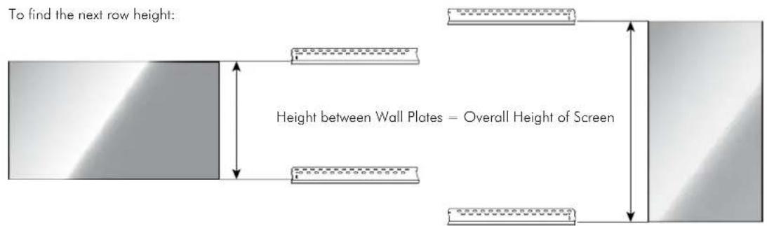
text_image
To find the next row height: Height between Wall Plates – Overall Height of ScreenStep 5. Mounting screens
5.1.
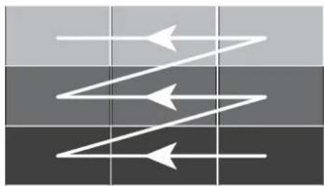
Install the screens row by row, starting at the bottom. Ensure each row of screens are level before moving on to the next row.
Installation may start from left or right.
natural_image
Abstract diagram with three white arrows pointing in different directions on a dark grid background (no text or symbols)Screen shown in Landscape orientation

flowchart
graph TD
    A["Step 1"] --> B["Step 2"]
    B --> C["Step 3"]
Screen shown in Portrait orientation
Please use a Spirit Level during installation to ensure that the Screens are LEVEL

natural_image
Pure diagram of a rectangular object with a triangular top and base, no text or symbols present5.2.

natural_image
Technical diagram showing a mechanical assembly with a hatched vertical section and an arrow indicating motion (no text or symbols present)Angle the screen as shown and position so the hook is above the bracket

text_image
Technical diagram showing a mechanical assembly with labeled components and directional arrows indicating motion or force.Drop the hook onto the bracket to engage and gently lower the screen
natural_image
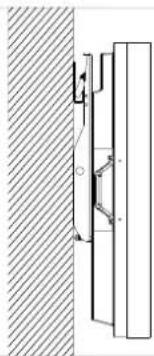
Technical diagram showing a mechanical assembly with a vertical rod and mounting bracket, adjacent to a hatched wall (no text or symbols)5.3. - Screen Levelling 5.3. - Wall Levelling
text_image
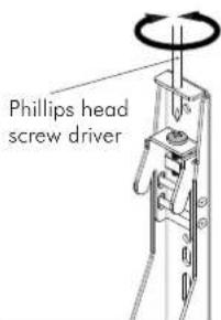
Phillips head screw driver
text_image
+/- 5mmLevel the screen by adjusting the screw at the top of each mounting bracket. Use a spirit level to ensure screen is level.
natural_image
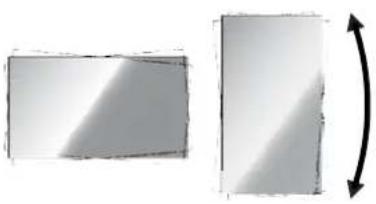
Two rectangular shapes with shading and a curved arrow indicating rotation (no text or symbols)
text_image
Levelling boltTo adjust for uneven walls, screw the leveling bolt in or out to match each display position.
Step 6. Cabling
6.1. - Cabling sequence

natural_image
Abstract diagram with three white arrows pointing in different directions on a dark grid background (no text or symbols)Screen shown in Landscape orientation
Tilt up each row, starting at the top, leaving each screen out until all cabling is finished.
You may start from the left or right.

flowchart
graph TD
    A["Step 1"] --> B["Step 2"]
    B --> C["Step 3"]
Screen shown in Portrait orientation
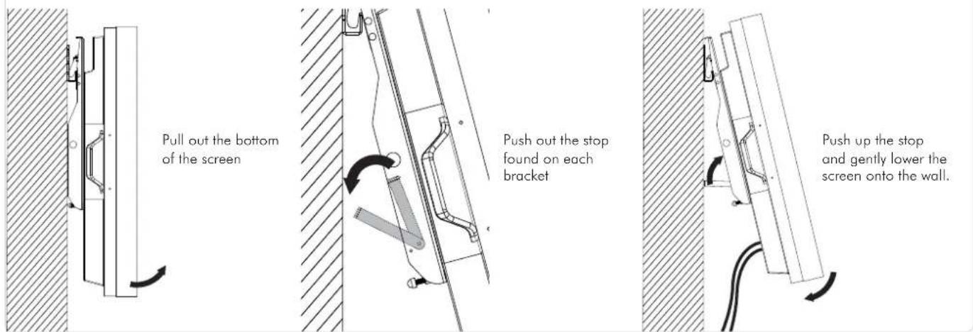
6.2. To gain access for cabling:
text_image
Pull out the bottom of the screen Push out the stop found on each bracket Push up the stop and gently lower the screen onto the wall.Step 7. Security (optional)
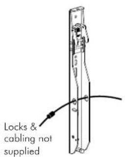
The holes shown in the bracket and wall plate can accommodate security cabling and locks.
text_image
Locks & cabling not supplied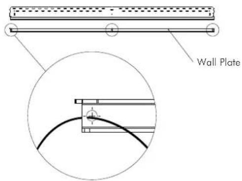
text_image
Wall PlateStep 8. Screen Removal
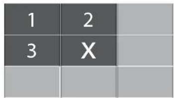
To remove screen X for repair or replacement, tilt up the numbered screens in sequence, then pull out and lift off screen X.
text_image
1 2 3 X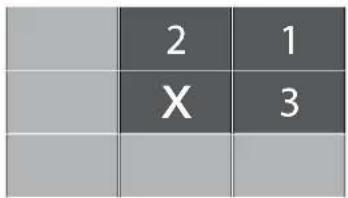
text_image
2 1 X 3| 1 | ||
| 2 | ||
| X |
Installation complete!