
PB650 - Video projector VIEWSONIC - Free user manual and instructions
Find the device manual for free PB650 VIEWSONIC in PDF.


| Product Type | LCD Projector |
| Display Technology | TFT Active Matrix |
| Native Resolution | 1024 x 768 (XGA) |
| Lamp Type | 150W UHB |
| Lamp Life | Approximately 2000 hours |
| Speaker | 1.0W monaural |
| Projection Size | 30" to 300" |
| Keystone Correction | Digital (adjustable via menu or remote) |
| Lens | Zoom lens F=1.7~1.9, f=21.7~26.1 mm |
| Weight | 2.7 kg (6.04 lbs) |
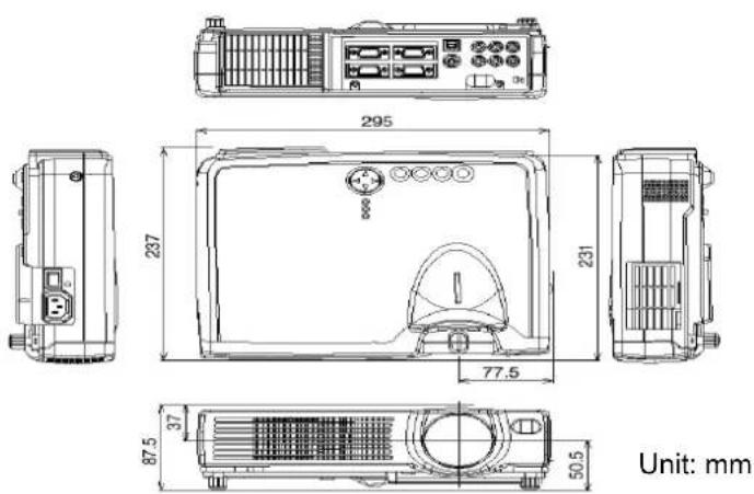
| Dimensions (W x H x D) | 295 x 87.5 x 237 mm (11.6 x 3.4 x 9.3 in) |
| Power Supply | AC 100-120V / 220-240V, 50/60Hz |
| Power Consumption | 240W (typical) |
| Input Ports | RGB IN (2), VIDEO IN, S-VIDEO IN, COMPONENT VIDEO (Y, Cb/Pb, Cr/Pr), AUDIO IN (R,L), CONTROL, USB |
| Output Ports | RGB OUT |
| Remote Control | Infrared with front and rear sensors (range 3m, 60°) |
| Air Filter | Cleanable (every 100 hours); replace if damaged |
| Lamp Replacement | User-replaceable (lamp part # RLU-150-001) |
| Warranty | 3 years parts and labor (excluding lamp) |
| Plug and Play | VESA DDC 1/2B compatible (via RGB IN 1) |
Frequently Asked Questions - PB650 VIEWSONIC
User questions about PB650 VIEWSONIC
0 question about this device. Answer the ones you know or ask your own.
Ask a new question about this device
Download the instructions for your Video projector in PDF format for free! Find your manual PB650 - VIEWSONIC and take your electronic device back in hand. On this page are published all the documents necessary for the use of your device. PB650 by VIEWSONIC.
USER MANUAL PB650 VIEWSONIC
natural_image
Line drawing of a projector with ventilation grilles and control knobs (no text or symbols)Image Size 31" - 300"
LCD Projector
Contents
For Your Records 1
Before Use 2
Package Contents 2
Using the remote control ....5
Putting batteries into the remote control unit ....5
Operating the remote control ....5
Setting up the projector 6
Adjusting the Projector's Elevator Feet ....6
Adjusting the Screen Size and Projection Distance 7
Ports and Cables 8
SetUp Reminders 9
Connecting your devices 10
Plug & Play 10
Connecting to a Computer ....11
Connecting to a DVD Player or VCR 12
Connecting to a Display Monitor 13
Turning On The Power 14
Precautions ...... 14
Turning Off The Power 15
Selecting an Input Signal 16
Adjusting the Volume 17
Temporarily Muting the Sound 17
Adjusting the Image Position .... 18
Using the Automatic Adjustment Feature 19
Correcting Keystone Distortions ....20
Using the Magnify Feature 21
Freezing the Screen 21
Signal Searching 22
Selecting the Aspect Ratio 22
Temporarily Blanking the Screen 22
Using the Menu Functions 23
Operating the PC Screen 24
PS/2, ADB, Serial Mouse Control 24
USB Mouse/Keyboard Control 24
OSD Menu Function Description ......25
Main Menu 25
Picture 1 Menu 26
Picture 2 Menu ....26
Input Menu 27
Screen Menu 28
Option Menu 30
Maintenance ....31
Lamp 31
Lamp Life 32
Replacing the Lamp 32
Caring for the Air Filter 33
Caring for the Inside of the Projector 34
Caring for the Lens 34
Caring for the Cabinet and Remote Control Transmitter ....34
Troubleshooting 35
On-screen Messages ....35
Panel Lamp Indicators 36
Problem Diagnostics ....37
Specifications 38
Outline Dimension 38
Customer Support 39
Limited Warranty 40
VIEWSONIC Projector 40
Appendix 41
Power Cord Safety Guidelines ....41
Compliance Information for U.S.A. 42
Compliance Information for Canada 42
Compliance Information for European Countries 42
User Information for all Countries 42
Copyright © ViewSonic Corporation, 2003. All rights reserved.
Apple, Mac and ADB registered trademarks of Apple Computer, Inc.
Microsoft, Windows, Windows NT, and the Windows logo are registered trademarks of Microsoft Corporation in the United States and other countries.
ViewSonic, the three birds logo A-CD-PJ650 and OnView are registered trademarks of ViewSonic Corporation.
VESA and SVGA are registered trademarks of the Video Electronics Standards Association.
DPMS and DDC are trademarks of VESA.
PS/2, VGA and XGA are registered trademarks of International Business Machines Corporation.
Disclaimer: ViewSonic Corporation shall not be liable for technical or editorial errors or omissions contained herein; nor for incidental or consequential damages resulting from furnishing this material, or the performance or use of this product.
In the interest of continuing product improvement, ViewSonic Corporation reserves the right to change product specifications without notice. Information in this document may change without notice.
No part of this document may be copied, reproduced, or transmitted by any means, for any purpose without prior written permission from ViewSonic Corporation.
Electronic Warranty Registration
To meet your future needs, and to receive any additional product information as it becomes available, please register your projector's warranty on the Internet at: http://www.viewsonic.com
For Your Records
| Product Name: | ViewSonic PJ650 |
| Model Number: | VPROJ27747-1W |
| Document Number: | A-CD-PJ650-1 |
| Serial Number: | |
| Purchase Date: |
Before Use
Package Contents
Make sure all of the following items are included in the package. If anything is missing, please contact ViewSonic Corp.
NOTE:
Keep the original packing material for future shipment.
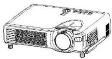
natural_image
Line drawing of a projector with ventilation grilles and a lens (no text or symbols)Projector
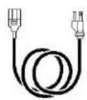
Power Cord Video/Audio Cable


USB mouse cable
Quick Start Guide
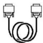
RGB Video Cable
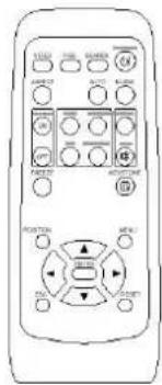
Remote Control
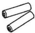
Remote ControlBatteries for

natural_image
Line drawing of a simple container with a logo and 'ViewSonic' text, no additional symbols or text present.Soft Case

CD-Wizard
NOTE:
Applicable power cord is shipped with the projector to the point of destination.
To avoid penetration of foreign objects, do not put the projector in a case or a bag together with any things except the accessories of the projector, signal cables and connectors.
WARNING:
Before using this equipment, read this manual thoroughly. Always ensure that the equipment is used safely.
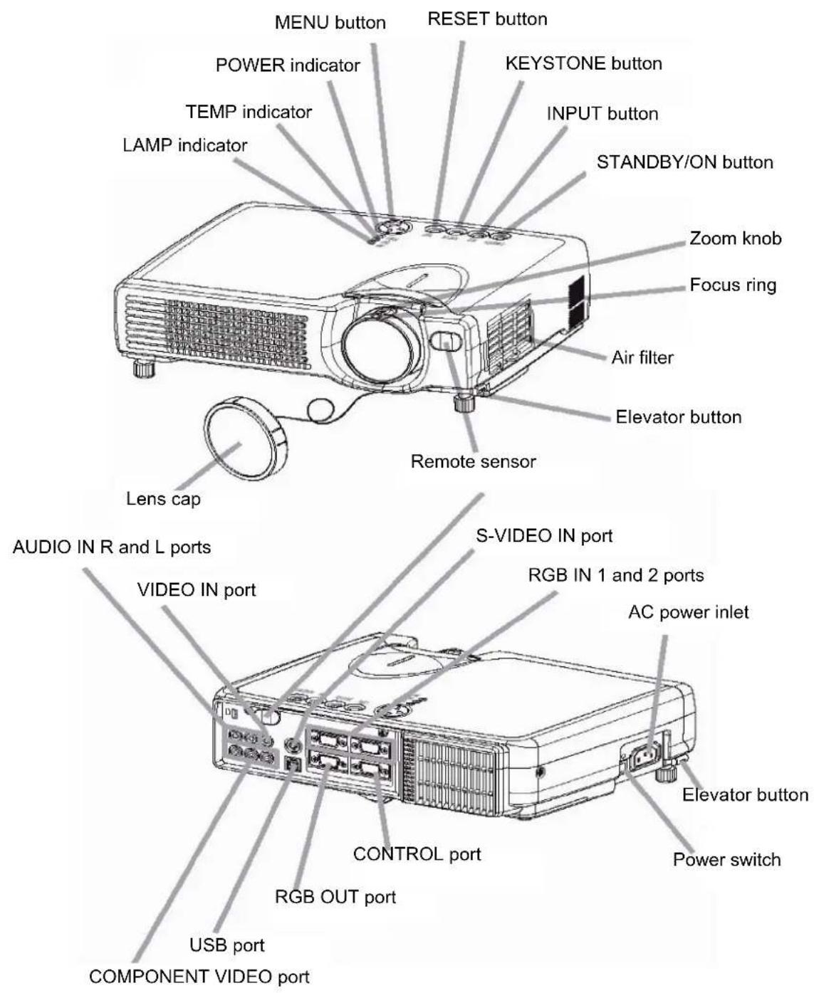
Component Names Projector
Remote Control
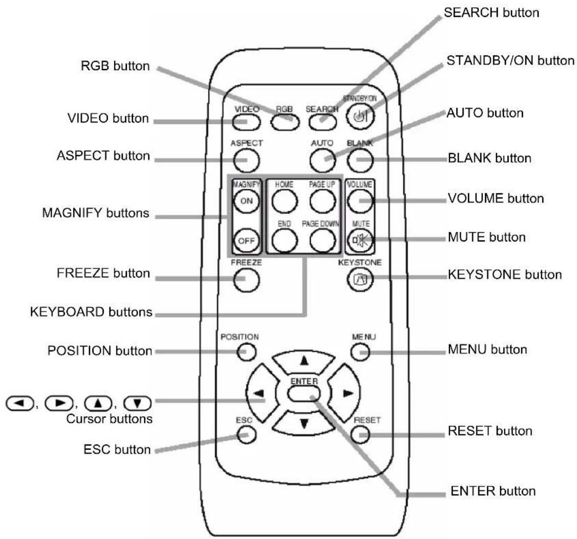
REMOTE CONTROL DEVICE
Using the remote control
Putting batteries into the remote control unit
CAUTION Precautions to observe in regards to the batteries
Always handle the batteries with care and use them only as directed. Improper use may result in battery cracking or leakage, which could result in fire, injury and/or pollution of the surrounding environment.
- Keep the battery away from children and pets.
- Be sure to use only the batteries specified for use with the remote control. Do not mix new batteries with used ones.
- When inserting batteries, verify that the plus and minus terminals are aligned correctly (as indicated in the remote control).
- When you dispose the battery, you should obey the law in the relative area or country.
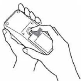
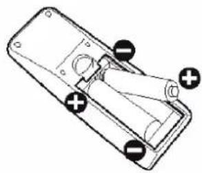
1 Remove the battery cover Slide back and remove the battery cover in the direction of the arrow.
2 Insert the batteries Align and insert the two AA batteries (that came with the projector) according to their plus and minus terminals (as indicated in the remote control).
3 Close the battery cover Replace the battery cover in the direction of the arrow and snap it back into place.
natural_image
Line drawing of a hand holding a handheld device (no text or symbols visible)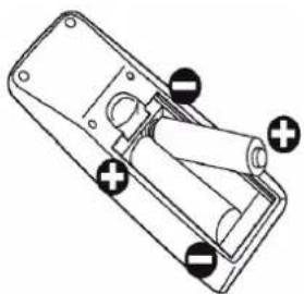
natural_image
Technical line drawing of a remote control casing with mounting holes and indicator lights (no text or symbols)
natural_image
Line drawing of a hand holding a handheld device (no text or symbols visible)Operating the remote control
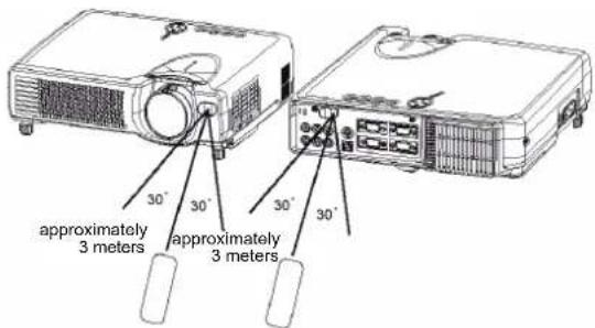
- The remote control works with both the projector's front and rear remote sensors.
- The range of the remote sensor on the front and back is 3 meters with a 60-degree range (30 degrees to the left and right of the remote sensor).
- Since the remote control uses infrared light to send signals to the projector (Class 1 LED), be sure to use the remote control in an area free from obstacles that could block the remote control's output signal to the projector.
ATTENTION Precautions to observe when using the remote control
- Do not drop or otherwise expose the remote control to physical impact.
- Do not get the remote control wet or place it on wet objects. Doing so may result in malfunction.
- Remove the batteries from the remote control and store them in a safe place if you won't be using the remote control for an extended period.
- Replace the batteries whenever the remote control starts to malfunction.
- When strong light, such as direct sunlight or light from an extremely close range (such as from an inverter fluorescent lamp), hits the projector's remote sensor, the remote control may cease to function. Adjust the direction of the projector to keep light from directly hitting the projector's remote sensor.
Setting up the projector
CAUTION
- Install the projector in a suitable environment according to instructions of the accompanying manual "PJ650 Quick START GUIDE" and this manual.
- If you press the elevator buttons without holding the projector, the projector might crash down, overturn, smash your fingers and possibly result in malfunction. To prevent damaging the projector and injuring yourself, ALWAYS HOLD THE PROJECTOR whenever using the elevator buttons to adjust the elevator feet.
Adjusting the Projector's Elevator Feet
You can use the elevator feet to make adjustments if the surface on which you need to set the projector is uneven or if you otherwise need to adjust the angle of projection. The adjustment range of the elevator feet is 0 to 9 degrees.
1 Press and hold in the elevator buttons.
2 Raise or lower the projector to the desired height and then release the elevator buttons. When you release the elevator buttons, the elevator feet will lock into position.
3 As necessary, you can also finely adjust the height of the projector by twisting the elevator feet by hand.

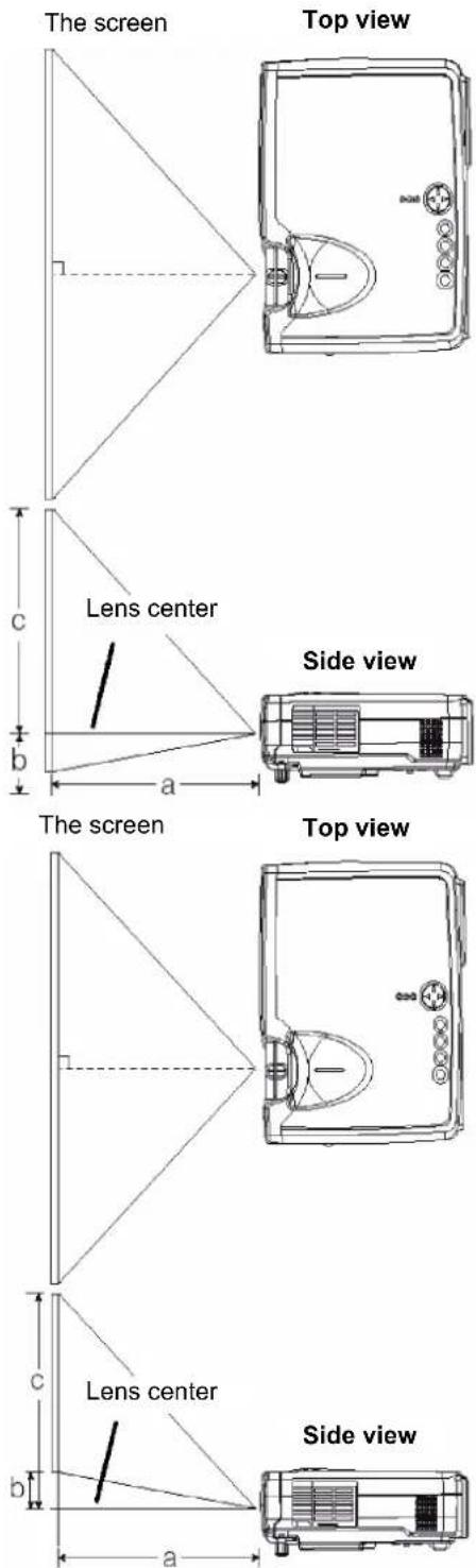
Adjusting the Screen Size and Projection Distance
Refer to the illustrations and tables below to determine the screen size and projection distance.
The values shown in the table are calculated for a full size screen (1024x768 pixels).
a: Distance from the projector to the screen (±10%).
b: Distance from the lens center to the bottom of the screen (±10%).
c: Distance from the lens center to the top of the screen (±10%).
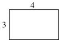
If 4:3 aspect ratio.
| Screen SizeInches (m) | a Inches (m)Minimum Maximum | b Inches(cm) | c Inches(cm) | |
| 30 (0.8) 35 | (0.9) 42 (1.1) | 1 (2) 17 (55) | ||
| 40 (1.0) 47 | (1.2) 56 (1.4) | 1 (3) 23 (58) | ||
| 50 (1.3) 59 | (1.5) 71 (1.8) | 1 (4) 29 (73) | ||
| 60 (1.5) 71 | (1.8) 85 (2.2) | 2 (4) 34 (87) | ||
| 70 (1.8) 83 | (2.1) 100 (2.5) | 2 (5) 40 (102) | ||
| 80 (2.0) 95 | (2.4) 114 (2.9) | 2 (6) 46 (116) | ||
| 90 (2.3) 107 | (2.7) 129 (3.3) | 3(7) 51 (131) | ||
| 100 (2.5) 119 | (3.0) 143 (3.6) | 3(7) 57 (145) | ||
| 120 (3.0) | 143 (3.6) | 172 (4.4) 3(9) | 69 (174) | |
| 150 (3.8) | 180 (4.6) | 216 (5.5) 4 (11) | 86 (218) | |
| 200 (5.0) | 240 (6.1) | 288 (7.3) | 6 (15) 114 (290) | |
| 250 (6.3) | 300 (7.6) | 361 (9.2) | 7 (18) | 143 (363) |
| 300 (7.5) | 360 (9.2) | 433 (11.0) | 9 (22) | 171 (435) |
If 16:9 aspect ratio.

| Screen Size Inches (m) | a Inches (m) | b Inches (cm) | c Inches (cm) | |
| Minimum | Maximum | |||
| 30 (0.8) | 38 (1.0) | 46 (1.2) 2 | (4) 16 (41) | |
| 40 (1.0) | 51 (1.3) | 61 (1.6) 2 | (5) 22 (55) | |
| 50 (1.3) | 64 (1.6) | 77 (2.0) 3 | (6) 27 (69) | |
| 60 (1.5) | 77 (2.0) | 93 (2.4) 3 | (8) 32 (82) | |
| 70 (1.8) | 90 (2.3) 10 | 9 (2.8) | 4 (9) 38 (96) | |
| 80 (2.0) | 104 (2.6) 12 | 25 (3.2) | 4 (10) 43 (110) | |
| 90 (2.3) | 117 (3.0) | 140 (3.6) | 5 (12) | 49 (124) |
| 100 (2.5) | 130 (3.3) | 156 (4.0) | 5 (13) | 54 (137) |
| 120 (3.0) | 156 (4.0) | 188 (4.8) | 6 (15) | 65 (165) |
| 150 (3.8) | 196 (5.0) | 235 (6.0) | 8 (19) | 81 (206) |
| 200 (5.0) 26 | 1 (6.6) 314 (8.0) | 10 (26) | 108 (275) | |
| 250 (6.3) 32 | 7 (8.3) 39 | 3 (10.0) | 3 (32) 135 (34 | 3 |
| 300 (7.5) 39 | 3 (10.0) 47 | 2 (12.0) | 15 (39) 162 (41 | 12 |
Ports and Cables
Refer to this table to determine which projector port and cable to use for connecting to a given device. Use this table for determining which cables to prepare.
| Function Projector | Port Connection Cables | |
| RGB input | RGB IN 1 | Accessory RGB cable or optional RGB cable with D-sub 15-pin shrink jack and inch thread screws |
| RGB IN 2 | ||
| RGB output RGB OUT | ||
| USB mouse control USB Accessory USB cable | ||
| PS/2 mouse control | ADB mouse cableCONTROL | Optional PS/2 mouse cable |
| ADB mouse control Optional A | ||
| Serial mouse control Optional serial mouse cable | ||
| RS-232C communication Optional RS-232C cable | ||
| S-video input S-VIDEO IN | Optional S-video cable with mini DIN 4-pin jack | |
| Video input VIDEO IN Accessory audio/video cable | ||
| Component video input | COMPONENT VIDEO Y | Optional component video cable |
| COMPONENT VIDEO C_B /P_B | ||
| COMPONENT VIDEO C_R /P_R | ||
| Audio input | AUDIO IN L | Accessory audio/video cable or optional audio cable with RCA jack |
| AUDIO IN R | ||
NOTE:
About Plug-and-Play Capability
- This projector is compatible with VESA DDC 1/2B. Plug-and-Play can be achieved by connecting this projector to computers that are VESA DDC (display data channel) compatible. Please take advantage of this function by connecting the accessory RGB cable to the RGB IN 1 port (DDC 1/2B compatible). Plug-and-Play may not work properly if any other type of connection is attempted.
- Plug-and-Play is a system composed of the computer, its operating system and peripheral equipment (i.e. display devices).
- Please use the standard drivers as this projector is a Plug-and-Play monitor.
- Plug-and-Play may not function properly with some type of computers. Use the RGB IN 2 port if Plug-and-Play does not function correctly.
SetUp Reminders
WARNING:
Precautions to observe in regards to the power cord: Please use extra caution when connecting the projector's power cord as incorrect or faulty connections may result in FIRE AND/OR ELECTRICAL SHOCK. Please adhere to the following safety guidelines to insure safe operation of the projector:
- Only plug the power cord into outlets rated for use with the power cord's specified voltage range.
- Only use the power cord that came with the projector.
- NEVER ATTEMPT TO DEFEAT THE GROUND CONNECTION OF THE THREEPRONGED PLUG!
- Make sure that you firmly connect the power cord to the projector and wall outlet.
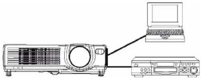
1 Connect your devices to the projector
Connect your computer, VCR and/or other devices you will be using to the projector.
natural_image
Line drawing of a projector connected to a laptop and a CD-ROM (no text or symbols present)2 Insert the batteries into the remote control.
natural_image
Technical line drawing of a remote control casing with mounting holes and internal components (no text or symbols)3 Connect the power cord
(1) Connect the connector of the electrical power cord to the AC inlet of the main unit.
(2) Firmly plug the power cord's into the outlet.

Connecting your devices
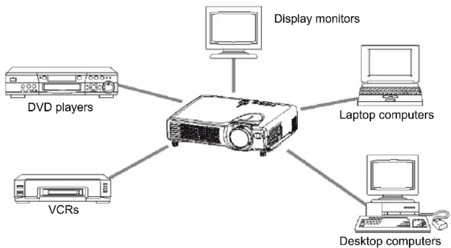
Devices You Can Connect to the Projector (Refer to this section for planning your device configuration to use for your presentation.)
CAUTION
- Incorrect connecting could result in fire or electrical shock. Please read this manual and the separate "PJ650 Quick START GUIDE".
ATTENTION Precautions to observe when connecting other devices to the projector
- Whenever attempting to connect other devices to the projector, please thoroughly read the manual of each device to be connected.
- TURN OFF ALL DEVICES prior to connecting them to the projector. Attempting to connect a live device to the projector may generate extremely loud noises or other abnormalities that may result in malfunction and/or damage to the device and/or projector. Refer to the “TECHNICAL” of the PJ650 User Guide for the pin assignment of connectors and RS-232C communication data.
- Make sure that you connect devices to the correct port. Incorrect connection may result in mal-function and/or damage to the device and/or projector.
- A component cable and some other cables have to be used with core set. Use the accessory cable or a designated type cable for the connection. For cables that have a core only at one end, connect the core to the projector.
- Secure the screws on the connectors and tighten.
flowchart
graph TD
    A["DVID player"] --> B["Protractor"]
    C["VCRs"] --> B
    D["Laptop computers"] --> B
    E["Desktop computers"] --> B
    F["Computer monitor"] --> B
    G["Display monitors"] --> B
NOTE:
When connecting the projector to a notebook computer, set it so as to activate the RGB external image output (setting it to CRT display or to simultaneous LCD and CRT display). For more information, refer to the instruction manual of the notebook computer.
Plug & Play
This projector is compatible with VESA DDC 1/2B. Plug & Play is possible by connecting to a computer that is compatible with VESA DDC (Display Data Channel).
Use this function by connecting the accessory RGB cable with RGB IN 1 terminal (DDC 1/2B compatible).
Plug & Play may not operate by any other connection.
NOTE:
- Plug & Play is a system configured with peripheral equipment which includes a computer, display and an operating system.
- This projector is recognized as a Plug & Play monitor. Load the driver contained in the CD Wizard included with the unit.
Connecting to a Computer
ATTENTION: Whenever attempting to connect a laptop computer to the projector, be sure to activate the laptop's RGB external image output (set the laptop to CRT display or to simultaneous LCD and CRT display). For details on how this is done, please refer to the laptop computer's instruction manual of the corresponding laptop computer.

NOTE:
- Some computers may have multiple display screen modes. The use of some of these modes may not be possible with this projector.
- For some RGB input modes, the optional Mac adapter is necessary.
Connecting to a DVD Player or VCR
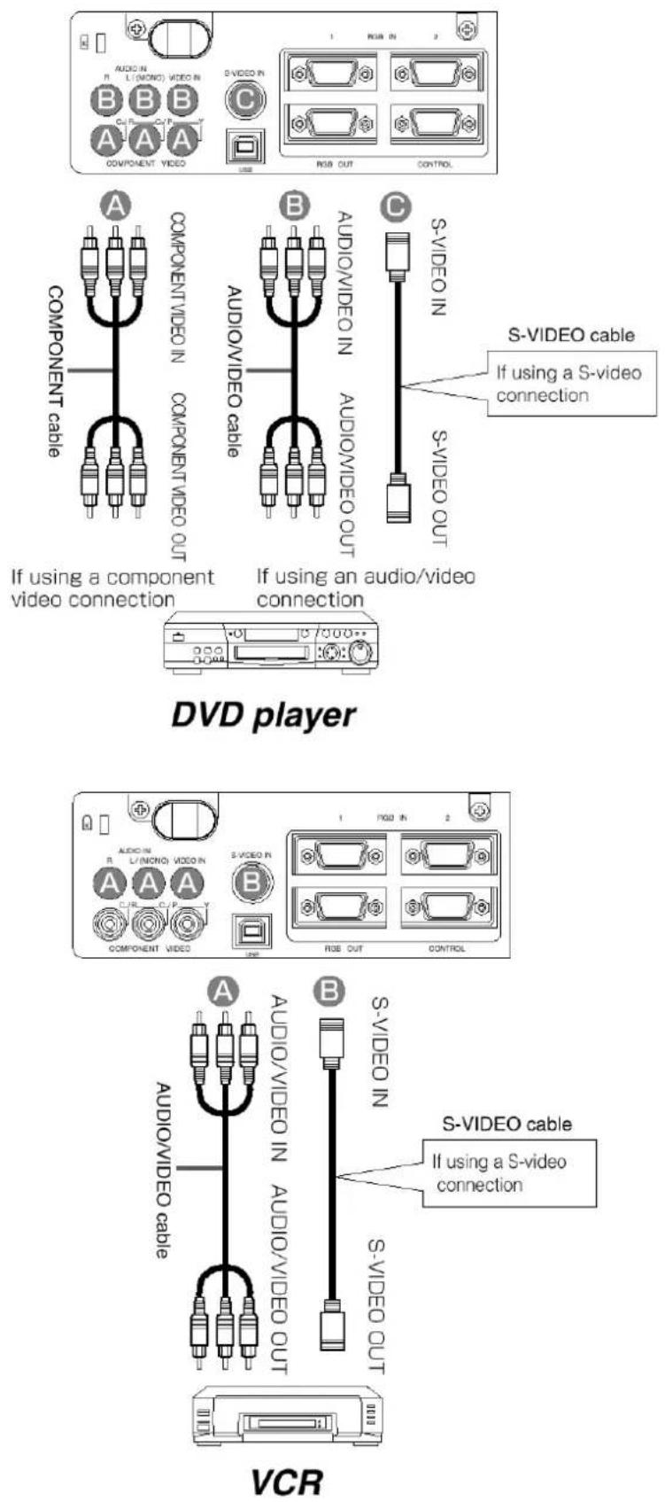
Connecting to a Display Monitor

Turning On The Power
Precautions
Connect all devices to be used to the projector prior to turning on the power.
WARNING: When the power is ON, a strong light is emitted. Do not look into the lens.
1 Make sure that the power cord is firmly and correctly connected to the projector and outlet.
2 Turn on the projector's power
Set the power switch to [ | ] (ON). The projector will go to STANDBY mode and the POWER indicator will light to solid orange.

3 Press the STANDBY/ON button (control panel or remote control)
- The projector begins warming up and the POWER indicator blinks green.
- The POWER indicator stops blinking and lights to solid green once the projector's power is completely on.

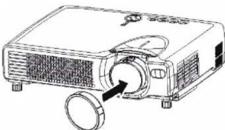
4 Remove the lens cap The picture is projected.

natural_image
Line drawing of a projector with a circular button and arrow indicating rotation (no text or symbols)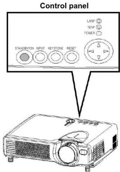
NOTE:
Turn the power on/off in right order.
- Power on the projector before the computer or video tape recorder.
- Power off the projector after the computer or video tape recorder.
Turning Off The Power
1 Press the STANDBY/ON button (control panel or remote control)
The message "Power off?" will appear on the screen for approximately 5 seconds.
2 Press the STANDBY/ON button again
(control panel or remote control)
Press the STANDBY/ON button again while the "Power off?" message is visible. The projector lamp goes off and starts cooling down. The POWER indicator blinks orange while the lamp cools down. (Pressing the STANDBY/ON button while the POWER indicator is blinking orange has no effect.)
The system goes into STANDBY mode, after cooling down the POWER indicator stops blinking orange and then lights to solid orange.

3 Check that the POWER indicator stops blinking and lights to solid orange.
Switch the power switch to [O] (OFF).
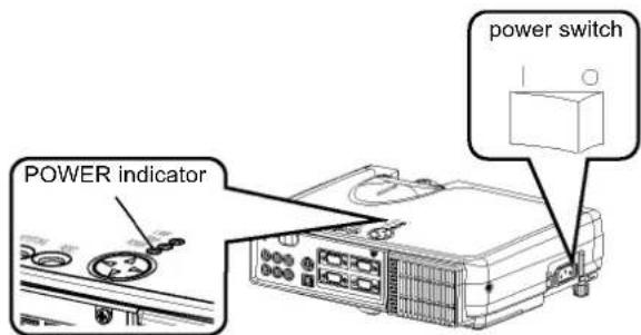
4 Confirm that the POWER indicator has gone off and then attach the lens cap.
When the projector has completed powering down, the POWER indicator will go off.
natural_image
Line drawing of a projector with a circular button and arrow indicating the handle (no text or symbols present)
NOTE:
Except in emergencies, follow the abovementioned procedure for turning power off.
Selecting an Input Signal
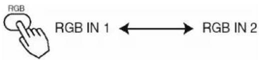
Using the remote control If selecting RGB input Press the RGB button
Press this button to toggle between the devices connected to RGB IN 1 and 2. As illustrated below, each time you press the RGB button, the projector switches between RGB IN 1 and 2.
Select the signal you wish to project.
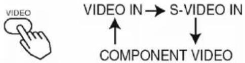
If selecting video input Press the VIDEO button
Press this button to toggle between the devices connected to VIDEO IN, SVIDEO IN and COMPONENT VIDEO. As illustrated below, each time you press the VIDEO button, the projector switches between VIDEO IN, S-VIDEO IN and COMPONENT VIDEO. Select the signal you wish to project.
flowchart
graph TD
    A["VIDEO IN"] --> B["S-VIDEO IN"]
    B --> C["COMPONENT VIDEO"]
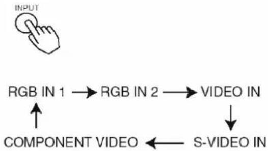
Using the projector's control panel Press the INPUT button
As illustrated below, each time you press the INPUT button, the projector switches between its input signal ports. Select the signal you wish to project.
flowchart
graph TD
    A["INPUT"] --> B["RGB IN 1"]
    B --> C["RGB IN 2"]
    C --> D["VIDEO IN"]
    D --> E["S-VIDEO IN"]
    E --> F["COMPONENT VIDEO"]
    F --> G["↑"]
Use the zoom ring to adjust the screen size

natural_image
Diagram of a hand inserting a circular component into a device housing (no text or symbols visible)Use the focus ring to focus the picture

natural_image
Illustration of a hand operating a circular device with a scroll wheel (no text or symbols visible)Adjusting the Volume
1 Press the VOLUME button
As illustrated on the right, a dialog box will appear on the screen to aid you in adjusting the volume.

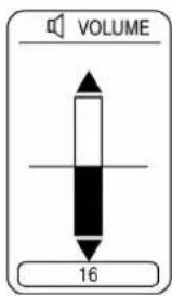
2 Press the ▲, ▼ buttons to adjust the volume
Press the VOLUME button again to close the dialog box and complete this operation. (Even if you don't do anything, the dialog box will automatically disappear after a few seconds.)

▲ Press this to increase the volume
▼ Press this to decrease the volume

Temporarily Muting the Sound
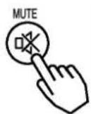
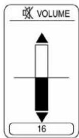
1 Press the MUTE button
As illustrated on the right, a dialog box will appear on the screen indicating that you have muted the sound. Press the VOLUME button to close the dialog box (Even if you don't do anything, the dialog box will automatically disappear after a few seconds.)
Press the MUTE button again to restore the sound.
Adjusting the Image Position
1 Press the POSITION button
As illustrated on the right, a dialog box will appear on the screen to aid you in adjusting the position.

2 Use the ◀, ▶, ▲, ▼ buttons to adjust the position
When you want to initialize the position, press the RESET button during adjustment.
Press the POSITION button again to close the dialog box and complete this operation. (Even if you don't do anything, the dialog box will automatically disappear after a few seconds.)
This function is only available for RGB IN 1/2 input.

flowchart
graph TD
    A["Hand Click"] --> B((Circular Interface))
    B --> C["Monitor 1"]
    B --> D["Monitor 2"]
    B --> E["Monitor 3"]
    B --> F["Monitor 4"]
    C --> G["Arrow Up"]
    D --> H["Arrow Down"]
    E --> I["Arrow Up"]
    F --> J["Arrow Down"]
Using the Automatic Adjustment Feature
1 Press the AUTO button

2 Automatic Adjustment for RGB Input
Horizontal position (H. POSIT), vertical position (V. POSIT), clock phase (H. PHASE) and horizontal size (H. SIZE) are automatically adjusted.
Make sure that the application window is set to its maximum size prior to attempting to use this feature.
Dark pictures may still be incorrectly adjusted. Use a bright screen when adjusting.
3 Automatic Adjustment for Video Input
The signal type best suited for the respective input signal is selected automatically.
This feature is available only if VIDEO is set to AUTO in the INPUT menu.
NOTE:
The automatic adjustment operation requires approximately 10 seconds. Also, please note that it may not function correctly with some input signals.
Correcting Keystone Distortions
1 Press the KEYSTONE button
As illustrated on the right, a dialog box will appear on the screen to aid you in correcting the distortion.


2 Use the ◀, ▶ buttons to select the direction of distortion to correct (☐ / ∅)

3 Use the ▲, ▼ buttons to correct the distortion
Press the KEYSTONE button again to close the dialog box and complete this operation. (Even if you don't do anything, the dialog box will automatically disappear after a few seconds.)

NOTE:
- This function may not be work well with some types of input signals.
- The adjustable range for correcting keystone distortions will vary with the type of input signal.
Using the Magnify Feature
1 Press the MAGNIFY (ON) button The projector enters MAGNIFY mode.
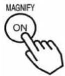
2 Press the POSITION button, then use the ◀, ▶, ▲, ▼ buttons to select the area to enlarge and then press the POSITION button again to confirm your selection.

flowchart
graph LR
    A["POSITION"] --> B["Rotation"]
    B --> C["OUTPUT"]
3 Press the ▲, ▼ buttons to zoom in and out of the selected area. Press the MAGNIFY (OFF) button to exit MAGNIFY mode and restore the screen to normal. (The projector will also automatically exit MAGNIFY mode if there is a change in the input signal's state.)
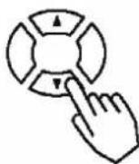
NOTE: The projector will automatically exit from MAGNIFY mode if either the INPUT SELECT, AUTO, ASPECT or VIDEO feature is used, or if there is a change in the input signal's state.
Freezing the Screen
1 Press the FREEZE button The icon appears and the screen will freeze at the current image. Press the FREEZE button again and the appears as the projector exits FREEZE MODE.

NOTE:
- The projector will automatically exit FREEZE mode if either the POSITION, VOLUME, MUTE, AUTO, BLANK ON/OFF, or MENU ON/OFF feature is used, or if there is a change in the input signal's state.
- If the projector continues projecting the same image for a long time (i.e. you forget to exit FREEZE mode), the image might possibly remain as an afterimage. Do not leave the projector in FREEZE mode for too long.
Signal Searching
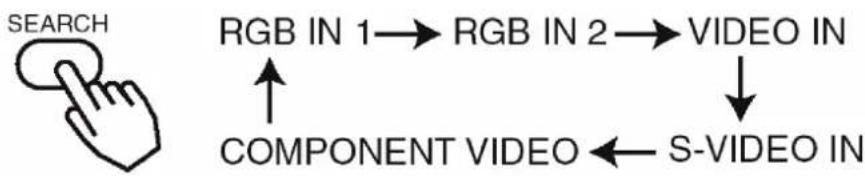
1 Press the SEARCH button
When you press the SEARCH button, the projector begins searching for input signals. If it detects an input signal, the search will cease and the projector will project the detected signal. If the projector is unable to find an input signal at any of its ports, it will return to the state it was in prior to the search.
flowchart
graph TD
    A["RGB IN 1"] --> B["RGB IN 2"] --> C["VIDEO IN"]
    D["COMPONENT VIDEO"] <--_E["S-VIDEO IN"]
    F["SEARCH"] --> A
    F --> C
Selecting the Aspect Ratio
1 Press the ASPECT button

RGB IN 1, RGB IN 2, COMPONENT VIDEO
(HDTV signals : 1125i (1035i/1080i), 750p)
4:3←16:9
VIDEO IN, S-VIDEO IN, COMPONENT VIDEO
(Non-HDTV signals : 525i, 525p,625i)

Temporarily Blanking the Screen
1 Press the BLANK button
The input signal screen is shut off, and a blank screen appears. You can set the blank screen using the menu (from the SCREEN menu, select BLANK). Press the BLANK button again to remove the blank screen, and return to the input signal screen.

Using the Menu Functions
1 Press the MENU button
The menu display appears on the screen. The projector has the following menus: MAIN, PICTURE 1, PICTURE 2, INPUT, SCREEN, and OPTION.
Select a menu using the ▲ / ▼ buttons. The current settings of the items that can be manipulated via the selected menu appear.

2 Select a menu using the ▲ / ▼ buttons, then press the ⬆ ENTER button.
The display for the selected menu appears.
[ex. Adjusting SHARPNESS]
Use the ▲ / ▼ buttons to select PICTURE 1, then press the ▶ or ENTER button.

flowchart
graph TD
    A["User Interface"] --> B["Enter Button"]
    B --> C["Arrow to Start"]
    C --> D["Arrow to End"]
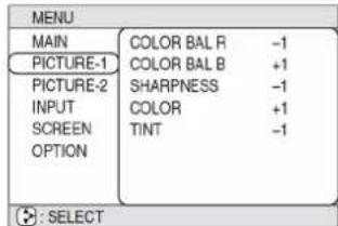
3 Select an item using the ▲ / ▼ buttons, then press the ▶ or the ENTER button.
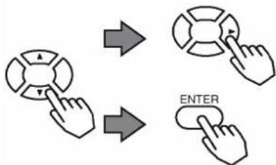
The operation display of the selected item appears. To adjust a numerical value, press the ▶ or ENTER button again to switch to the single menu (small display showing only the operation display area).
[ex. Adjusting SHARPNESS]
Use the ▲ / ▼ buttons to select SHARPNESS, then press the ▶ or the ENTER button.
flowchart
graph TD
    A["User Interface"] --> B["Enter Button"]
    B --> C["User Interface"]

4 Press the ▲ / ▼ buttons to adjust the level.
Press the MENU button to hide the menu and finish your operation. Alternatively, press the ◀ or ESC button to return to the previous display.
[ex. Adjusting SHARPNESS]
Use the ▲ / ▼ buttons to adjust the SHARPNESS.
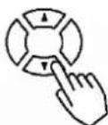
Operating the PC Screen
You can use the remote control as a simplified mouse or keyboard.
CAUTION: Mistaken use of the mouse/keyboard control could damage your equipment.
- Only connect to a PC.
- Before connecting, read the manuals of the device you will connect.
- Do not unplug the connector cables while the computer is operating.
PS/2, ADB, Serial Mouse Control
1 Turn off the projector and PC power, and connect the projector's CONTROL terminal to the computer via the mouse cable.
2 If a USB cable is connected, disconnect it. If a USB cable is connected, the USB control function is given priority, and mouse control from the CONTROL terminal will not function.
3 Turn on the projector power, then the computer.
The functions in the table below can be controlled. If you have difficulty with control, restart the computer (either from the software or by pressing the restart button).
| Available Functions Remote Control Operation | |
| Move Pointer | Use ▲, ▶, ▲, ▼ button |
| Left click with mouse Press ENTER button | |
| Right click with mouse Press RESET button | |
USB Mouse/Keyboard Control
1 Connect the projector's USB terminal to the computer using a USB cable. The functions in the table below can be controlled.
| Available Functions Remote Control Operation | |
| Move Pointer | Use ▲, ▶, ▲, ▼ button |
| Left click with mouse Press ENTER button | |
| Right click with mouse Press RESET button | |
| Press keyboard's HOME key Press HOME button | |
| Press keyboard's END key Press END button | |
| Press keyboard's PAGE UP key Press PAGE | UP button |
| Press keyboard's PAGE DOWN key Press PAGE | PAGE DOWN button |
| Press keyboard's ESC key Press ESC button | |
NOTES:
- It may not be possible to control notebook PCs, and other computers with built-in pointing devices (e.g. track balls), using this remote control. In this case, before connecting go into BIOS (system setup) and select external mouse, and disable the pointing devices. In addition, the mouse may not function if the computer does not have the needed utility program. See your computer's hardware manual for details.
- The USB control can be used with Windows 95 OSR 2.1 or higher. It may not be possible to use the remote control, depending on the computer's configurations and mouse drivers.
- The USB control can only be used for the functions listed above. You cannot do things like press two buttons at once (for instance, pressing two buttons at the same time to move the mouse pointer diagonally).
- This function is not available while the lamp is warming up (the POWER indicator flashes green), while adjusting the volume and display, correcting for trapezoidal distortion, zooming in on the screen, using the BLANK function, or displaying the menu screen.
OSD Menu Function Description
This device has 6 separate menus: MAIN, PICTURE 1, PICTURE 2, INPUT, SCREEN and OPTION. Each of these menus is operated using the same methods.
The basic operations of these menus are as follows.
| Menu screen display Press the "MENU" button. | |
| Menu selection | Choose a menu name using the /▲button▼ and press the button or the ENTER button. |
| Item selection | Choose an item using the /▲button▼ and press the button or the ENTER button. |
| Return menu to last previous screen | Press the button or the ESC button. |
| Execution of settings and/or adjustments | Operate by using the /▲button▼(For further details, read the explanation for each separate menu.) |
| Initialization of settings and/or adjustments | During operation, press the RESET button. (Note that items whose functions are performed simultaneously with the operation of clock phase, language selection, automatic adjustment, etc., cannot be initialized.) |
| End menu operations | Press the MENU button, or do not perform any operation for several seconds. |
Main Menu
With the MAIN menu, the seven items shown in the Table below can be performed.
Perform each operation in accordance with the instructions in the Table.

| Item | Description |
| BRIGHT | Adjust Brightness: Light ▼ ⇔ ▲ Dark |
| CONTRAST | Adjust Contrast: Strong ▼ ⇔ ▲ Weak |
| ASPECT Select Aspect Ratio:At RGB Input or Hi-Vision 1125i(1035i/1080i)/750p of COMPONENT VIDEO Input:4:3 ▼ ⇔ ▲ 16:9At VIDEO Input, S-VIDEO Input or 525i/525p/625i of COMPONENT VIDEO Input:4:3 ▼ ⇔ ▲ ▼ ⇔ 16:9 SMALLThe SMALL picture may not be displayed correctly with certain input signals. | |
| PICT. POSIT. Select Picture Position (for 16:9/SMALL Picture):TOP CENTER BOTTOM ▼ ⇔ ▲ | |
| GAMMA Select Gamma Mode:NORMAL GINEMA DYNAMIC ▼ ⇔ ▲ | |
| MIRROR Select Mirror Status:NORMAL HINVERT ▲ INVERT H&VINVERT ▲ ▼ ⇔ ▲ | |
| LANGUAGE Select Menu Language:ENGLISH FRANCAIS DEUTSCH ESPAÑO ▲ ▼ ⇔ ▲▼ ⇔ ▲ITALIANO NORSK NEDERLANDS ▼ ⇔ ▲日本語 ▼ ⇔ ▲ VOTUGUŠ 中文 | |
Picture 1 Menu
With the PICTURE 1 menu, the five items shown in the Table below can be performed.
Perform each operation in accordance with the instructions in the Table.

| Item | Description | |
| COLOR BAL R | Adjust Red Color Balance: Dark ▼ ⇔ ▲ | Light |
| COLOR BAL B | Adjust Blue Color Balance: Dark ▼ ⇔ ▲ | Light |
| SHARPNESS | Adjust Sharpness (for VIDEO/S-VIDEO): Clear ▼ ⇔ ▲ | Soft |
| COLOR Adjust COLOR (for VIDEO/S-VIDEO/COMPONENT VIDEO): Dark ▼ ⇔ ▲ Light | ||
| TINT | Adjust Tint (for VIDEO/S-VIDEO): Green ▼ ⇔ ▲ | Red |
Picture 2 Menu
With the PICTURE 2 menu, the five items shown in the Table below can be performed.
Perform each operation in accordance with the instructions in the Table.
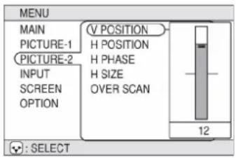
| Item Description | |
| V POSITION | Adjust Vertical Position (for RGB): Up ▼ ⇔ ▲ Down |
| H POSITION | Adjust Horizontal Position (for RGB): Left ▼ ⇔ ▲ Right |
| H PHASE Adjust Horizontal Phase (for RGB/COMPONENT VIDEO):Right ▼ ⇔ ▲ LeftAdjust to eliminate flicker. | |
| H SIZE | Adjust Horizontal Size (for RGB): Large ▼ ⇔ ▲ SmallIf the horizontal size adjustment is excessive, the image may not be displayed correctly. In such a case, initialize H SIZE with the RESET button. |
| OVER SCAN Select Over-scan Ratio (for VIDEO/S-VIDEO/COMPONENT VIDEO):LARGE MIDDLE SMALL ▼ ⇔ ▲It is recommended to select SMALL to avoid flicker at the lower part of the picture. | |
Input Menu
With the INPUT menu, the four items shown in the Table below can be performed. With inputting of RGB IN 1 and RGB IN 2 signals, the horizontal and vertical frequencies of the signals will be displayed on the initial screen of the INPUT menu.
Perform each operation in accordance with the instructions in the Table.

| Item Description | |
| AUTO Auto Adjust | (for RGB): Automatically adjusts H POSITION, V POSITION, H PHASE, and H SIZE. Use this function with the maximum window size.Auto Adjust (for VIDEO/S-VIDEO): Automatically selects the proper VIDEO mode for the current input signal. This function is active only when the AUTO mode is selected for the item VIDEO. Refer to the description for the item VIDEO below.This function may not be available with a PAL60 signal and certain other signals.The AUTO mode operation requires approximately 10 seconds.For COMPONENT VIDEO, the signal type is identified automatically even if this function is inactive. For a HDTV signal, refer to the item HDTV below. |
| VIDEO Select Mode | of Signal Type (for VIDEO/S-VIDEO):AUTO [NTSC-PAL] SECAM [V] ⇔ [▲] [V] ⇔ [▲] [▼] ⇔ [▲] NTSC4.43 [W-PAL] N-PAL [▼] ⇔ [▲]Selecting AUTO mode activates and performs the AUTO function for VIDEO/SVIDEO. It automatically selects the proper mode from among those above. Use this function if the image becomes unstable with VIDEO/S-VIDEO. (e.g. The image becomes irregular, or lacks color.)• AUTO mode may not function correctly with a PAL60 signal and certain other signals.• The AUTO mode operation requires approximately 10 seconds.• For COMPONENT VIDEO, the signal type is identified automatically even if this func- tion is inactive. For a HDTV signal, refer to the item HDTV below. |
| HDTV Select HDTV | Signal Mode:1080i [▼] ⇔ [▲] 1035i• If the selected HDTV mode is incompatible with the input signal, the picture may be distorted. |
| SYNC ON G On/Off | SYNC ON G Mode:TURN ON [TURN-OFF]Selecting TURN ON turns on the SYNC ON G mode. The SYNC ON G mode allows reception of SYNC on G.• In the SYNC ON G mode, the picture may be distorted with certain input signals. In such cases, remove the signal connector so that no signal is received and turn SYNC ON G off, and then reconnect the signal. |
Screen Menu
With the SCREEN menu, the five items shown in the Table below can be performed.
Please perform each operation in accordance with the instructions in the Table.
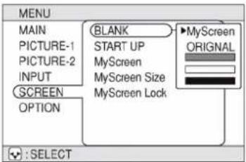
| Item Description | |
| BLANK Selection | of BLANK Screen:MyScreen ⇌ ▲ [IMAGE]The BLANK Screen may be voluntarily selected. The BLANK Screen is displayed when the screen has been erased (i.e., made to vanish) by manipulating the BLANK button (please refer to the “Temporarily Blanking the Screen” section of the separate booklet, Vol. 1 (Basic)).MyScreen: Using the MyScreen category (see this Table, below), one can register a desired screen (or screens). At the time of factory shipment, this is set as a non-patterned (plain) blue color screen.ORIGINAL: Existing standard screens. Please make confirmation using the actual screen(s).Option screens: Various colored non-patterned (plain) screens displayed within the Menus.• The MyScreen and the ORIGINAL Screen will each change to a non-patterned (plain) black color screen several minutes after being displayed. |
| START UP Selection | on of START UP Screen:MyScreen ORIGINAL TURN OFF ⇌ ▲The START UP Screen may be voluntarily selected. The START UP Screen is displayed when no signal has been inputted, or when spec signals are being inputted.MyScreen: Using the MyScreen category (see this Table, below), one can register a desired screen (or screens). At the time of factory shipment, this is set as a non-patterned (plain) blue color screen.ORIGINAL: Existing standard screens. Please make confirmation using the actual screen(s).TURN OFF: A non-patterned (plain) blue color screen.• The MyScreen and the ORIGINAL Screen will each change to the BLANK Screen several minutes after being displayed. |
| MyScreen Registration of MyScreen:When this item is executed, the MyScreen Menu for registration of MyScreen for the BLANK Screen and the START UP Screen is displayed. When operations are performed in accordance with this Menu, one can “cut” and register desired screens from among the received images within the display.1. After the “Do you start capturing this picture?” message has been displayed, pressing the ESC (or RESET) button interrupts execution of the MyScreen. When the ENTER button is pressed, the picture becomes static (no longer moves), and a frame for picture cutting, as well as the message that follows below, appear. Please press the but- ton when the screen you want to register is currently being displayed.2. When the “Move the capture area as you want.” message has been displayed, pressing the ESC (or RESET) button will eliminate the static state of the picture, and operations can be performed again from operation 1. The frame can be moved using the [◀], [▶], [▲], [▼] buttons. After designating the screen you want to register, pressing the ENTER button will initiate screen registration. The registration process takes approximately 1 minute to complete.3. When the registration has been completed, the screen of the registered MyScreen, and the message, “MyScreen registration is finished,” will be displayed for several seconds, after which the operation is terminated. | |
| MyScreen Size Selection of MyScreen display size:x1 [▼] ⇔ [▲] FULL | |
| MyScreen Lock Invalidation of MyScreen registration function:TURN ON [TURN OFF ▲]When TURN ON is selected, the MyScreen category (see this Table, above) cannot be executed. In this way, one can prohibit rewrites (“writeovers”) of the MyScreen | |
Option Menu
With the OPTION menu, the five items shown in the Table below can be performed.
Please perform each operation in accordance with the instructions in the Table.
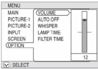
| Item Description | |
| VOLUME | Adjust Volume: High ▼ ⇔ ▲ Low |
| AUTO OFF Adjust AUTO OFF Time:Long (MAX. 99 min.) Short(Min.▲ min.) (DISABLE: 0 min.) The ▲ system automatically enters the standby mode if no signal is received within the set time. This function is inactive when DISABLE (0 min.) is selected. | |
| WHISPER Select WHISPER Mode:NORMAL ▼ ⇔ ▲ WHISPERWhen WHISPER is selected the WHISPER mode is activated. In the WHISPER mode, acoustic noise and screen brightness are reduced. | |
| LAMP TIME Refer to LAMP TIME: When set, this function displays the total time the projector lamp has been used since new.Reset LAMP TIME [Use this function only when the lamp has been replaced!]:Depress the RESET button for at least 3 seconds while lamp time is being displayed. The reset menu will then appear. After you replace the lamp with a new lamp, select RESET on the menu with the ▲ button.Do not reset the lamp time unless you have replaced the lamp. And, always reset the lamp time when replacing the lamp. The message functions will not operate properly if the lamp time is not reset correctly.After the lamp running reaches 2000 hours, a warning message is displayed: “To maximize performance, lamp replacement is recommended.”, but won’t shut the unit off. The message display for 30 seconds when the PJ is turned on. If we push any button while displaying the message, the message disappears.Before replacing the lamp, carefully read the descriptions headed "THE LAMP". | |
| FILTER TIME Refer to FILTER TIME: This function displays the total time the air-filter has been used since new.Reset FILTER TIME [Use this function only when the filter is cleaned or replaced!]:Depress the RESET button for at least 3 seconds while lamp time is being displayed. The reset menu will then appear. After you replace the filter, select RESET on the menu with the ▲ button.DEFAULT ▼ ⇔ ▲ CANCELDo not reset the filter time unless you have cleaned or replaced the filter. And, always reset the filter time when cleaning or replacing the filter. The message functions will not operate properly if the filter time is not reset correctly.Before cleaning or replacing the filter, carefully read the descriptions headed "THE AIR FILTER". | |
Maintenance
Lamp
To order a new lamp unit (Lamp Part # RLU-150-001), contact ViewSonic or your dealer. For the lamp part number, see the Optional Parts in the Specifications in this guide. For contact information, see the Customer Support table in this guide. Before replacing the lamp, turn the Power Switch OFF, remove the power cord from the power outlet, then wait at least 45 minutes until the lamp has cooled.
CAUTION: The lamp may explode if handled at high temperatures.


HIGH VOLTAGE
HIGH TEMPERATURE
HIGH PRESSURE

WARNING
The projector uses a high-pressure mercury glass lamp made of glass. The lamp can break with a loud bang, or burn out, if jolted or scratched, handled while hot, or worn over time. Note that each lamp has a different lifetime, and some may burst or burn out soon after you start using them. In addition, when the bulb bursts, it is possible for shards of glass to fly into the lamp housing, and for gas containing mercury to escape from the projector's vent holes
- If the lamp should break (it will make a loud bang when it does), unplug the power cord from the outlet, and make sure to request a replacement lamp from your local dealer. Note that shards of glass could damage the projector's internals, or cause injury during handling, so please do not try to clean the projector or replace the lamp yourself.
- If the lamp should break (it will make a loud bang when it does), ventilate the room well, and make sure not to breathe the gas that comes out of the projector vents, or get it in your eyes or mouth.
- Do not open the lamp cover while the projector is suspended from above. This is dangerous, since if the lamp's bulb has broken, the shards will fall out when the cover is opened. In addition, working in high places is dangerous, so ask your local dealer to have the lamp replaced even if the bulb is not broken.
- If the indicators or a message prompts you to replace the lamp (see the section “Related Messages” and “Regarding the indicator Lamps”), replace the lamp as soon as possible. Using the lamp for long periods of time, or past the replacement date, could cause it to burst. Do not use old (used) lamps; this is a cause of breakage.
- If the lamp breaks soon after the first time it is used, it is possible that there are electrical problems elsewhere besides the lamp. If this happens, contact your local dealer or a service representative.
- Use the lamp of the specified type only. (sold separately)
- Handle with care: jolting or scratching could cause the lamp bulb to burst during use.
- Before replacing the lamp, make sure the power switch is off and the power cable is not plugged in, then wait at least 45 minutes for the lamp to cool sufficiently. Handling the lamp while hot can cause burns, as well as damaging the lamp.
- Do not use the projector with the lamp cover removed. At the lamp replacing, make sure that the screws are screwed in firmly. Loose screws could result in damage or injury.
- Obey local ordinances when disposing of used lamps. In most cases, it is possible to dispose of used bulbs in the same manner as used glass bottles, but in some cases, bulbs are sorted separately.
Lamp Life
Projector lamps have a finite life. The projected images will become darker and hues will become weaker after a lamp has been used for a long period of time.
The LAMP indicator also becomes red when the lamp unit reaches a high temperature. Before replacing the lamp, switch the POWER OFF, wait approximately 20 minutes, then switch the POWER ON again. If the LAMP indicator still displays red, replace the lamp.
Replacing the Lamp
All projector lamps will wear out eventually. If used for long periods of time, the image could become darkened, and the color contrast could be impacted as well. We recommend that you replace your lamps early. If the LAMP indicator turns red, or a message prompts you to replace the lamp when you power up the projector, the lamp needs to be replaced.
1 Turn off the projector, and unplug the power cord. Allow the lamp bulb to cool for at least 45 minutes, and prepare a new lamp
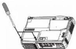
2 After making sure that the projector has cooled adequately, slowly flip over the projector, so that the bottom is facing up
3 Unscrew the 2 screws, and remove the lamp cover
natural_image
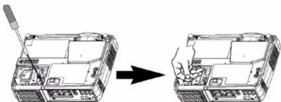
Line drawing of a portable electronic device with a screwdriver inserted, no visible text or symbols4 Unscrew the 1 screw, and slowly pull out the lamp by the handle
- Be careful not to touch the inside of the lamp case.
natural_image
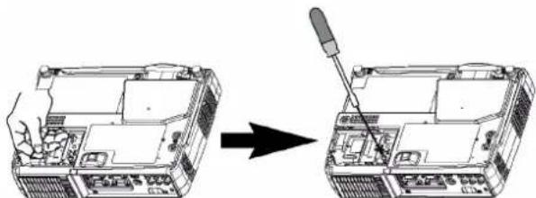
Diagram showing a device being processed from a tool, with no visible text or symbols5 Insert the new lamp, and tighten the 1 screw firmly to lock it in place
- Also steadily push the opposite side of the screwed side of the lamp into the unit.
natural_image
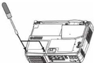
Diagram showing a device being inserted into a chassis, with a screwdriver inserted (no text or symbols present)6 Replace the lamp cover, and tighten the 2 screws firmly to lock it in place
natural_image
Line drawing of a device with a screwdriver inserted, showing internal components and no text or symbols7 Slowly turn the projector so that the top is facing up
8 Turn on the projector power, and using the menu, reset the lamp timer
- To reset the lamp timer, from the OPTION menu, select LAMP TIME.
ATTENTION:
- Make sure that the screws are screwed in firmly. Loose screws could result in damage or injury.
- Do not use with lamp cover removed.
- Do not reset the lamp timer without replacing the lamp.
NOTE:
The LAMP indicator is also red when the lamp unit reaches high temperature.
Before replacing the lamp, switch power OFF, wait approximately 20 minutes, and switch power ON again. If the LAMP indicator is still red, replace the lamp.
Caring for the Air Filter
The air filter should be cleaned about every 100 hours. Clean the filter if the LAMP indicator and TEMP indicator blink red simultaneously, or if a message prompts you to clean the air filter when you turn on the unit, the filter needs to be cleaned. (Refer to “On-Screen Messages” in the Trouble-shooting section.)
1 Turn off the projector, then unplug the power cord
2 To clean a reusable filter, carefully vacuum both sides of the filter area.

3 If the filter is damaged and needs to be replaced, contact your dealer or ViewSonic Corp. Replace the old filter then put the grill back in place.
4 To reset the Filter Timer, turn on the projector power, go to the Option menu then select filter timer. Reset the filter timer.
CAUTION:
- Switch power OFF and remove the power cord from the power outlet before beginning maintenance work.
- Replace the air filter if contamination cannot be removed or if it is damaged.
- Do not use the equipment with the air filter removed.
- When the air filter becomes clogged with dust etc., the power supply may switch OFF automatically to prevent the temperature from rising inside the projector.
- Make sure the lens is cool before cleaning.
- Do not use detergents or solvents such as benzene or thinners.
- Do not use chemical sprays.
- Use a soft cloth or lens paper only.
Caring for the Inside of the Projector
In order to ensure the safe use of your projector, please have it cleaned and inspected by an authorized Service Provider approximately once every 2 years. Never try to care for the inside of the unit yourself. Doing so is dangerous.
Caring for the Lens
Lightly wipe the lens with a commercially available lens-cleaning wipe. Do not touch the lens directly with your hand.
Caring for the Cabinet and Remote Control Transmitter
Wipe lightly with gauze or a soft cloth. If soiling is severe, dip a soft cloth in water or a neutral cleanser diluted in water, and wipe lightly after wringing well. Then, wipe lightly with a soft, dry cloth.
CAUTION:
- Make sure to turn off the power and unplug the power cord before caring for the unit. Please care-fully read all the PJ650 Quick START GUIDE in this manual, in order to care for your projector correctly.
- Do not use cleaners or chemicals other than those listed above, including benzene and paint thinner.
- Do not use aerosols or sprays.
- Do not polish or wipe with coarse material.
- Gently wipe with a soft cloth. If dirt and stains etc. are not easily removed, use a soft cloth dampened with water, or water and a neutral detergent, and wipe dry with a soft, dry cloth.
Troubleshooting
On-screen Messages
When the unit's power is ON, messages such as those shown below may be displayed. When any such message is displayed on the screen, please respond as described below.
| Message Description | |
| TO MAXIMIZE PERFORMANCE, LAMP REPLACEMENT IS RECOMMENDED. | The unit does not display a warning message on the screen when the lamp expires or fails. When the lamp does not light, this indicates that the lamp is no longer functional and should be replaced. Replace the lamp and do not forget to reset the timer. |
| CLEAN THE AIR FILTER AFTER CLEANING AIR FILTER, RESET THE FILTER TIMER. | A note of precaution when cleaning the air filter.After cleaning the filter, operate FILTER TIME of the OPTION Menu, then perform reset of the filter timer. |
| NO INPUT IS DETECTED ON *** | There is no input signal.Check the signal input connection and the status of the signal source. |
| SYNC IS OUT OF RANGE ON *** | The horizontal or vertical frequencies of the inputted signal is outside of the operating range limits of this unit. Please confirm the specs for this unit or the signal source specs. |
| CHECK THE AIR FLOW | The internal temperature is rising. Please turn the power OFF, then allow the unit to cool down for approximately 20 minutes. After having confirmed the following items, then please reset the power to ON.Is there blockage of the air filter?Is the air filter dirty?Does the ambient temperature exceeds 35°C? |
Panel Lamp Indicators
Lighting and flashing of the POWER indicator, the LAMP indicator, and the TEMP indicator have the meanings as described in the Table below.
Please respond in accordance with the instructions within the Table.
| POWER indicator | LAMP indicator | TEMP indicator | Description |
| The orange lamp is lighted | Turned OFF (Not lighted) | Turned OFF (Not lighted) | The STANDBY mode is set |
| Flashing of the green lamp | Turned OFF Turned OFF The unit is warming up. Please wait. | ||
| The green lamp is lighted | Turned OFF Turned OFF The unit is in an ON state. Ordinary operations may be performed. | ||
| Flashing of the orange lamp | Turned OFF Turned OFF The unit is cooling down. Please wait. | ||
| Blinking of the red lamp | -- The unit is cooling down. Please wait.A certain error has been detected. Wait until the POWER indicator lamp has finished flashing, and then perform the proper response measure using the item descriptions below as reference. | ||
| The red lamp is lighted, or blinks | The red lamp is lighted | Turned OFF The lamp does not light.There is a possibility that the interior portion has become heated. Turn the power OFF and wait approximately 20 minutes. After the main unit has cooled down, please confirm whether or not there is blockage of the air passage aperture, whether or not the filter is dirty, and/or whether or not the peripheral temperature exceeds 35°C, etc. After performing any needed maintenance, turn the power ON again; if the same display is displayed, then please change the lamp. | |
| The red lamp is lighted, or blinks | Blinking of the red lamp | Turned OFF Either there is no lamp and/or lamp cover, or either of these has not been properly fixed (attached). Turn the power OFF and wait approximately 45 minutes. After the main unit has sufficiently cooled down, please make confirmation of the attachment state of the lamp and lamp cover. After performing any needed maintenance, turn the power ON again; if the same display is displayed, then please contact a sales store or a service company. | |
| The red lamp is lighted, or blinks | Turned OFF Blinking of the red lamp | The cooling fan is not operating. Turn the power OFF and wait approximately 20 minutes. After the main unit has cooled down, please make confirmation that no foreign matter has become caught in the fan, etc. After performing any needed maintenance, turn the power ON again; if the same display is displayed, then please contact a sales store or a service company. | |
| The red lamp is lighted, or blinks | Turned OFF The red lamp is lighted | There is a possibility that the interior portion has become heated. Turn the power OFF and wait approximately 20 minutes. After the main unit has cooled down, please confirm whether or not there is blockage of the air passage aperture, whether or not the filter is dirty, and/or whether or not the peripheral temperature exceeds 35°C, etc. After performing any needed maintenance, turn the power ON again; if the same display is displayed, then please contact a sales store or a service company. | |
| The green lamp is lighted | Alternative blinking with the red lamp | There is a possibility that the interior portion has become overcooled. Please use the unit within the usage temperature parameters (0°C to 35°C). After performing any needed maintenance, turn the power ON again; if the same display is displayed, then please contact a sales store or a service company. | |
| The green lamp is lighted | Simultaneous blinking with the red lamp | This is a notification that it is time to clean the filter. After cleaning the filter, operate the FILTER TIME portion of the OPTION Menu, and perform reset of the FILTER TIME. | |
NOTE:
When the interior portion has become overheated, for safety purposes, the power source is automatically turned OFF, and the indicator lamps may also be turned OFF. Press the "O" (power OFF) side of the main power switch, and wait for approximately 20 minutes. Please then use the unit only after having first confirmed that the unit has sufficiently cooled down.
Problem Diagnostics
Before requesting repair, please check the following chart. If the situation cannot be corrected, then contact your dealer.
| Phenomenon Cases not involving a machine defect | Items to be confirmed | |
| Power does not come ON | The main power source is not ON. | Turn on the main power. |
| The electrical power cord is not plugged in. | Correctly connect the power cord. points. | |
| The main power source has been interrupted during operation, such as by a power outage (blackout), etc. | Be sure to press the “O” (power OFF) side of the main power switch, and leave this OFF for approximately 20 minutes. After the unit has sufficiently cooled down, turn ON the power source. | |
| No sound or pictures are outputted | The input changeover settings are mismatched. | Select the input signal, and correct the settings. |
| The input changeover settings are mismatched. | Correctly connect the connection cord. | |
| No signal is being inputted. Correctly connect the connection cord. | ||
| Pictures are displayed, but no sounds are heard | The electrical wiring to this unit is not correctly connected. | Correctly connect the connection cord. |
| The volume setting has been set at (or adjusted to) an extremely low level. | Adjust the VOLUME setting to a higher level. | |
| MUTE is turned on. Press the MUTE button to toggle the MUTE mode setting.. | ||
| Sounds are heard, but no pictures are displayed | The electrical wiring to this unit is not correctly connected. | Correctly connect the connection cord. |
| The brightness setting has been set at (or adjusted to) an extremely low level. | Adjust the BRIGHT setting to a brighter level. | |
| The lens cap has not been removed. | Remove the lens cap. | |
| Colors have a faded-out appearance.Color tone is poor | Color depth setting or color tone setting | Perform picture adjustments by changing the COLOR BAL R, the COLOR BAL B, and/or the TINT settings, etc. |
| Pictures appear dark | The brightness setting and/or contrast setting has not been properly adjusted. | Perform picture adjustments by changing the BRIGHT and/or CONTRAST settings, etc. |
| The WHISPER mode is the current setting. | Toggle from the WHISPER mode. | |
| Lamp is approaching the end of its product lifetime. | Repalce the Lamp Assembly. | |
| Pictures appear blurry | Either the FOCUS setting or the H PHASE is not properly adjusted. | Adjust the FOCUS and H PHASE settings. |
NOTE:
When the interior becomes overheated, power to the unit automatically shuts down. Press the main switch on the side of the unit to the off position then wait 20 minutes to allow the unit to cool down before any work is done to the unit.
Specifications
This specifications are subject to change without notice.
| Item Specification | ||
| Product name PJ650 | ||
| Liquid crystal projector | Panel size 1.8 cm | (0.7 type) |
| Drive system TFT | active matrix | |
| Pixels 786,432 pixels (1024 horizontal x 768 vertical) | ||
| Lens Zoom lens F=1.7 ~ 1.9 =21.7~26.1 mm | ||
| Lamp 150 W UHB | ||
| Speaker 1.0W | ||
| Power supply AC100 ~ 120V, 2.7A / AC220 ~ 240V, 1.3A | ||
| Power consumption 240W (typ.) | ||
| Temperature range 0 ~ 35°C (32~95°F) (Operating) | ||
| Size 295 (W) x 87.5 (H) x 237 (D) mm11.6 (W) x 3.4 (H) x 9.3 (D) inches | ||
| Weight (mass) | 2.7 kg (6.04 lbs) | |
| Ports | RGB TerminalAUDIO TerminalRGB IN (1,2)......2AUDIO IN (R, L)......1VIDEO TerminalOUT TerminalVIDEO IN......1RGB OUT......1S-VIDEO IN......1CONTROL TerminalCOMPONENT VIDEOCONTROL......1(Y, CB/PB/, CR/PR)......1USB......1 | |
| Optional Parts | Lamp:RLU-150-001ViewSonic offers other accessories including items such as air filters, remote controls,ceiling mounting brackets, manuals, soft cases, etc. Please contact your dealer orViewSonic for information. | |
Outline Dimension
Customer Support
For technical support or product service, see the table below or contact your reseller.
When calling ViewSonic Customer Support please have the product's model name and serial number on hand.
| Country/Region Web site T = Telephone | F = FAX | ||
| United States viewsonic.com/support | T: (800) 688-6688F: (909) 468-1202 | service.us@viewsonic.com | |
| Canada viewsonic.com/support | T: (800) 688-6688F: (909) 468-1202 | service.ca@viewsonic.com | |
| United Kingdom viewsoniceurope.com | T: 0800 833 648F: (01293) 643910 | service.eu@viewsoniceurope.com | |
| Europe, Middle East,Baltic countries, andNorth Africa | viewsoniceurope.com Contact your reseller service.eu@ | viewsoniceurope.com | |
| Australia and New Zealand | viewsonic.com.au | T: +61 2 9929 3955F: +61 2 9929 8393 | service@au.viewsonic.com |
| Singapore/India and Southeast Asia | viewsonic.com.sg | T: 65 6273 4018F: 65 6273 1566 | service@sg.viewsonic.com |
| Other Asia/Pacific countries | viewsonic.com.tw | T: 886 2 2246 3456F: 886 2 8242 3668 | service@tw.viewsonic.com |
| South Africa viewsonic.com | asia | T: 886 2 2246 3456F: 886 2 8242 3668 | service.ap@viewsonic.com |
LIMITED WARRANTY VIEWSONIC PROJECTOR
What the warranty covers:
ViewSonic ^® warrants its products to be free from defects in material and workmanship during the warranty period. If a product proves to be defective in material or workmanship during the warranty period, ViewSonic will at its sole option repair or replace the product with a like product. Replacement product or parts may include remanufactured or refurbished parts or components.
How long the warranty is effective:
ViewSonic projectors are warranted for three (3) years for all parts excluding the lamp and three (3) years for all labor from the date of the first consumer purchase. Projector lamps are warranted separately.
Who the warranty protects:
This warranty is valid only for the first consumer purchaser.
What the warranty does not cover:
- Any product on which the serial number has been defaced, modified or removed.
- Damage, deterioration or malfunction resulting from:
a. Accident, misuse, neglect, fire, water, lightning, or other acts of nature, unauthorized product modification, or failure to follow instructions supplied with the product.
b. Repair or attempted repair by anyone not authorized by ViewSonic.
c. Any damage of the product due to shipment.
d. Removal or installation of the product.
e. Causes external to the product, such as electric power fluctuations or failure.
f. Use of supplies or parts not meeting ViewSonic's specifications.
g. Normal wear and tear.
h. Any other cause which does not relate to a product defect.
- Removal, installation, and set-up service charges.
How to get service:
- For information about receiving service under warranty, contact ViewSonic Customer Support. You will need to provide your product's serial number.
- To obtain warranted service, you will be required to provide (a) the original dated sales slip, (b) your name, (c) your address, (d) a description of the problem, and (e) the serial number of the product.
- Take or ship the product freight prepaid in the original container to an authorized ViewSonic service center or ViewSonic.
- For additional information or the name of the nearest ViewSonic service center, contact ViewSonic.
Limitation of implied warranties:
THERE ARE NO WARRANTIES, EXPRESS OR IMPLIED, WHICH EXTEND BEYOND THE DESCRIPTION CONTAINED HEREIN INCLUDING THE IMPLIED WARRANTY OF MERCHANTABILITY AND FITNESS FOR A PARTICULAR PURPOSE.
Exclusion of damages:
VIEWSONIC LIABILITY IS LIMITED TO THE COST OF REPAIR OR REPLACEMENT OF THE PRODUCT. VIEWSONIC SHALL NOT BE LIABLE FOR:
- DAMAGE TO OTHER PROPERTY CAUSED BY ANY DEFECTS IN THE PRODUCT, DAMAGES BASED UPON INCONVENIENCE, LOSS OF USE OF THE PRODUCT, LOSS OF TIME, LOSS OF PROFITS, LOSS OF BUSINESS OPPORTUNITY, LOSS OF GOODWILL, INTERFERENCE WITH BUSINESS RELATIONSHIPS, OR OTHER COMMERCIAL LOSS, EVEN IF ADVISED OF THE POSSIBILITY OF SUCH DAMAGES.
- ANY OTHER DAMAGES, WHETHER INCIDENTAL, CONSEQUENTIAL OR OTHERWISE.
- ANY CLAIM AGAINST THE CUSTOMER BY ANY OTHER PARTY.
Effect of state law:
This warranty gives you specific legal rights, and you may also have other rights which vary from state to state. Some states do not allow limitations on implied warranties and/or do not allow the exclusion of incidental or consequential damages, so the above limitations and exclusions may not apply to you.
Sales outside the U.S.A. and Canada:
For warranty information and service on ViewSonic products sold outside of the U.S.A. and Canada, contact ViewSonic or your local ViewSonic dealer.
Projector Warranty (V3.0) Release Date: May 1, 2002
Appendix
Power Cord Safety Guidelines
Caution: Use a power cable that is properly grounded. Always use an AC power cord that meets your country's safety standard.
USA...... UL
Switzerland ......SEV
Canada.... CSA
Britain......BASE/BS
Germany...... VDE
AC PLUG CORD PRECAUTIONS FOR THE UNITED KINGDOM
FOR YOUR SAFETY PLEASE READ THE FOLLOWING TEXT CAREFULLY.
IF THE FITTED MOULDED PLUG IS UNSUITABLE FOR THE SOCKET OUTLET THEN THE PLUG SHOULD BE CUT OFF AND DISPOSED OF SAFELY.
THERE IS A DANGER OF SEVERE ELECTRICAL SHOCK IF THE CUT OFF PLUG IS INSERTED INTO AN APPROPRIATE SOCKET.
If a new plug is to be fitted, please observe the wiring code as shown below.
If in any doubt, please consult a qualified electrician.
WARNING: THIS APPLIANCE MUST BE EARTHED.
IMPORTANT: The wires in this mains lead are coloured in accordance with the following code:
Green-and-Yellow: Earth
Blue: Neutral
Brown: Live
If the coloured wires of the mains lead of this appliance do not correspond with the coloured markings identifying the terminals in your plug, proceed as follows:
The wire which is coloured GREEN-AND-YELLOW must be connected to the terminal in the plug which is marked by the letter E or by the Earth symbol or coloured GREEN or GREEN-AND-YELLOW.
The wire which is coloured BLUE must be connected to the terminal in the plug which is marked with the letter N or coloured BLACK. The wire which is coloured BROWN must be connected to the terminal in the plug which is marked with the letter L or coloured RED.
IMPORTANT NOTICE CONCERNING POWER CORD SELECTION
The power cord set for this unit has been enclosed and has been selected according to the country of destination and must be used to prevent electric shock. Use the following guidelines if it is necessary to replace the original cord set, or if the cord set is not enclosed.
The female receptacle of the cord set must meet CEE-22 requirements and may look like (Figure A1 below):
Figure 1
For the United States and Canada
In the United States and Canada the male plug is a NEMA5-15 style (Figure A2), UL Listed, and CSA Labeled. For units which are mounted on a desk or table, type SVT cord sets may be used. The cord set must be selected according to the current rating for your unit. Please consult the table below for the selection criteria for power cords used in the United States and Canada.
Figure 2
For customers in Canada:
Notice: This Class B digital apparatus complies with Canadian ICES-003.
| Cord Type Size | of Conductors in Cord Maximum | Current Rating of Unit |
| SJT 18 AWG | 16 AWG14 AWG | 10 Amps12 Amps12 Amps |
| SVT 18 AWG | 17 AWG | 10 Amps12 Amps |
For European Countries
In Europe you must use a cord set which is appropriate for the receptacles in your country. The cord set is HAR-Certified, and a special mark that will appear on the outer sheath, or on the insulation of one of the inner conductors.
If you have any questions concerning which proper power cord to use, please consult with the dealer from whom you have purchased the product.
Compliance Information for U.S.A.
This equipment has been tested and found to comply with the limits for a Class B digital device, pursuant to part 15 of the FCC Rules. These limits are designed to provide reasonable protection against harmful interference in a residential installation. This equipment generates, uses, and can radiate radio frequency energy, and if not installed and used in accordance with the instructions, may cause harmful interference to radio communications. However, there is no guarantee that interference will not occur in a particular installation. If this equipment does cause harmful interference to radio or television reception, which can be determined by turning the equipment off and on, the user is encouraged to try to correct the interference by one or more of the following measures:
- Reorient or relocate the receiving antenna.
- Increase the separation between the equipment and receiver.
- Connect the equipment into an outlet on a circuit different from that to which the receiver is connected.
- Consult the dealer or an experienced radio/TV technician for help.
FCC Warning
To assure continued FCC compliance, the user must use grounded power supply cord and the provided shielded video interface cable with bonded ferrite cores. If a BNC cable is going to be used, use only a shielded BNC(5) cable. Also, any unauthorized changes or modifications not expressly approved by the party responsible for compliance could void the user's authority to operate this device.
Instructions to Users
This equipment complies with the requirements of FCC (Federal Communication Commission) equipment provided that the following condition is met. Use the cables which are included with the projector or specified.
Compliance Information for Canada
Notice: This class B digital apparatus complies with Canada ICES-003.
Compliance Information for European Countries
CE Conformity

The device complies with the requirements of the EEC directive 89/336/EEC as amended by 92/31/EEC and 93/68/EEC Art.5 with regard to “Electromagnetic compatibility,” and 73/23/EEC as amended by 93/68/EEC Art.13 with regard to “Safety.”
User Information for all Countries
NOTICE: Use the cables which are included with the projector or specified.

- Contents
- Before Use 2
- OSD Menu Function Description ......25
- Maintenance ....31
- Troubleshooting 35
- Specifications 38
- Customer Support 39
- Limited Warranty 40
- Appendix 41
- Electronic Warranty Registration
- For Your Records
- Before Use
- Package Contents
- NOTE:
- WARNING:
- Component Names Projector
- Remote Control
- Using the remote control
- Putting batteries into the remote control unit
- CAUTION Precautions to observe in regards to the batteries
- Operating the remote control
- ATTENTION Precautions to observe when using the remote control
- Setting up the projector
- CAUTION
- Adjusting the Projector's Elevator Feet
- Adjusting the Screen Size and Projection Distance
- Ports and Cables
- SetUp Reminders
- Connect your devices to the projector
- Connecting your devices
- Plug & Play
- Connecting to a Computer
- Connecting to a DVD Player or VCR
- Connecting to a Display Monitor
- Turning On The Power
- Precautions
- Turning Off The Power
- Selecting an Input Signal
- Using the remote control If selecting RGB input Press the RGB button
- If selecting video input Press the VIDEO button
- Using the projector's control panel Press the INPUT button
- Adjusting the Volume
- Press the VOLUME button
- Press the ▲, ▼ buttons to adjust the volume
- Temporarily Muting the Sound
- Press the MUTE button
- Adjusting the Image Position
- Press the POSITION button
- Use the ◀, ▶, ▲, ▼ buttons to adjust the position
- Using the Automatic Adjustment Feature
- Press the AUTO button
- Correcting Keystone Distortions
- Press the KEYSTONE button
- Using the Magnify Feature
- Freezing the Screen
- Signal Searching
- Press the SEARCH button
- Selecting the Aspect Ratio
- Temporarily Blanking the Screen
- Press the BLANK button
- Using the Menu Functions
- Press the MENU button
- Operating the PC Screen
- PS/2, ADB, Serial Mouse Control
- USB Mouse/Keyboard Control
- NOTES:
- OSD Menu Function Description
- Main Menu
- Picture 1 Menu
- Picture 2 Menu
- Input Menu
- Screen Menu
- Option Menu
- Maintenance
- Lamp
- HIGH VOLTAGE
- HIGH TEMPERATURE
- HIGH PRESSURE
- WARNING
- Lamp Life
- Replacing the Lamp
- ATTENTION:
- Caring for the Air Filter
- CAUTION:
- Caring for the Inside of the Projector
- Caring for the Lens
- Caring for the Cabinet and Remote Control Transmitter
- Troubleshooting
- On-screen Messages
- Panel Lamp Indicators
- Problem Diagnostics
- Specifications
- Outline Dimension
- Customer Support
- LIMITED WARRANTY VIEWSONIC PROJECTOR
- What the warranty covers:
- How long the warranty is effective:
- Who the warranty protects:
- What the warranty does not cover:
- How to get service:
- Limitation of implied warranties:
- Exclusion of damages:
- Effect of state law:
- Sales outside the U.S.A. and Canada:
- Appendix
- Power Cord Safety Guidelines
- AC PLUG CORD PRECAUTIONS FOR THE UNITED KINGDOM
- For the United States and Canada
- For customers in Canada:
- For European Countries
- Compliance Information for U.S.A.
- FCC Warning
- Instructions to Users
- Compliance Information for Canada
- Compliance Information for European Countries
- CE Conformity
- User Information for all Countries
Brand : VIEWSONIC
Model : PB650
Category : Video projector